by Denny Williams, Photos by Denny Williams 1962 IMPALA ...€¦ · Photo #3: As mentioned in the...
7
Photo #3: As mentioned in the introduction, you could do this entire procedure with the trunk lid installed on the car, but for our purposes of showing some good pictures and for ease of installation, we have removed the trunk lid and set it on an old blanket to protect the paint. "Pop" each of the taillight and backup light bulb assemblies out of the housings. Be sure to pull these out by the socket assemblies and not the wires. Photo #2: Using a 7/16-inch socket, remove the two cap-nuts which secure the taillight assembly. Remove the taillight assembly from the cove molding area. Using a 5/16-inch socket, remove the cap-nut from the studded clip that is embedded in the cove molding. This cap-nut should be located along the trunk opening towards the bottom of the cove molding. Remove the cove molding from the car. In Photo #2 you'll notice that there is some caulking that was placed between the body and the cove molding. Notice that there are three slotted areas on the cove molding for clips. To my knowledge, Chevrolet only used one clip on the cove molding and it is pointed out with the arrow in Photo #2. Repeat the first two steps for the other cove molding and set these aside for right now. by Denny Williams, Photos by Denny Williams 1962 IMPALA TRUNK PANEL RESTORATION Parts Needed: 511153 Impala SS Trunk Panel W/Cove Inserts 511152 Impala Trunk Panel W/Cove Inserts 561238 Trunk Panel Insert Clips 561239 Trunk Panel Cove Clips 511088 Trunk Panel Trim Bar 7-pc 511028 Trunk Panel Upper Molding 511038 Outer Cove Moldings (Hockey Sticks) 505064 Inner Taillight & Backup Light Seals 505036 Taillight & Backup Housing To Body Seals 502162 Complete Imp Taillight & Backup Assembly 88-0277-1 Body Strip Caulking 501058 Trunk Lid Emblem With Plastic Insert 501067 Plastic Insert Only 501093 Impala SS Trunk Emblem Photo #1: Each cove molding on the 1962 is held to the body by the "hockey stick" molding, the taillight assembly, and one clip which is embedded in the cove molding itself. Using a 5/16-inch socket, remove the three cap-nuts which hold the "hockey stick" molding in place. Remove the "hockey stick" with the 3- studded clips. (Hockey stick moldings P/N 511038.) Editor Note: With this issue being a 1962 50th Anniversary addition I wanted to feature a special 1962 tech article. I went back in our archives and found this trunk panel tech. In ‘97 this was truly a restoration, using many of the original pieces. Today every piece of this tech article is available as a reproduction part. It’s amazing how time flies (fourteen years later this tech article has greatly changed). Watch for the red copy and color photos from 2012! This month's Tech Check article will cover the restoration of the 1962 Impala or SS Impala rear trunk panel area. This article will explain the installation of the new 7-piece trim bars onto an original panel. (New back in ’97. See photo above.) Very nice new reproduction panels are available and have these bars already installed. These new reproduction trunk panels are available as "SS" panels or Impala panels (without the swirl pattern). These panels are manufactured by Specialty Chevrolet Products and they are currently considering reproducing the cove moldings. (1962 trunk panels now come as 3- piece kits including the cove inserts; ask for P/N 511152 or 511153). This entire restoration could be accomplished with the trunk lid left on the car, but it would be much easier if it is off. For that reason and for photographic purposes, we have removed the deck lid. So follow along and end up with a great looking rear trunk panel area on your 1962 Impala. 511152 #1 - P/N 511038 #2 #3
Transcript of by Denny Williams, Photos by Denny Williams 1962 IMPALA ...€¦ · Photo #3: As mentioned in the...

Photo #3: As mentioned in theintroduction, you could do thisentire procedure with the trunk lidinstalled on the car, but for ourpurposes of showing some goodpictures and for ease of installation,we have removed the trunk lid andset it on an old blanket to protectthe paint. "Pop" each of the taillightand backup light bulb assembliesout of the housings. Be sure to pullthese out by the socket assemblies and not the wires.
Photo #2: Using a 7/16-inch socket, remove the two cap-nutswhich secure the taillight assembly. Remove the taillightassembly from the cove molding area. Using a 5/16-inch socket,remove the cap-nut from the studded clip that is embedded inthe cove molding. This cap-nut should be located along thetrunk opening towards the bottom of the cove molding.Remove the cove molding from the car. In Photo #2 you'llnotice that there is some caulking that was placed between thebody and the cove molding. Notice that there are three slottedareas on the cove molding for clips. To my knowledge,Chevrolet only used one clip on the cove molding and it ispointed out with the arrow in Photo #2.Repeat the first two steps for the other cove molding and setthese aside for right now.
by Denny Williams, Photos by Denny Williams
1962 IMPALA TRUNK PANEL RESTORATION
Parts Needed:511153 Impala SS Trunk Panel W/Cove Inserts511152 Impala Trunk Panel W/Cove Inserts561238 Trunk Panel Insert Clips561239 Trunk Panel Cove Clips511088 Trunk Panel Trim Bar 7-pc511028 Trunk Panel Upper Molding511038 Outer Cove Moldings (Hockey Sticks)505064 Inner Taillight & Backup Light Seals505036 Taillight & Backup Housing To Body Seals502162 Complete Imp Taillight & Backup Assembly88-0277-1 Body Strip Caulking501058 Trunk Lid Emblem With Plastic Insert501067 Plastic Insert Only501093 Impala SS Trunk Emblem
Photo #1: Each covemolding on the 1962 isheld to the body by the"hockey stick" molding,the taillight assembly,and one clip which isembedded in the covemolding itself. Using a5/16-inch socket,
remove the three cap-nuts which hold the "hockey stick"molding in place. Remove the "hockey stick" with the 3-studded clips. (Hockey stick moldings P/N 511038.)
Editor Note: With this issue being a 1962 50th Anniversary addition Iwanted to feature a special 1962 tech article. I went back in our archivesand found this trunk panel tech. In ‘97 this was truly a restoration, usingmany of the original pieces. Today every piece of this tech article isavailable as a reproduction part. It’s amazing how time flies (fourteenyears later this tech article has greatly changed). Watch for the redcopy and color photos from 2012!
This month's Tech Check article will cover the restoration of the 1962Impala or SS Impala rear trunk panel area. This article will explain theinstallation of the new 7-piece trim bars onto an original panel. (New backin ’97. See photo above.) Very nice new reproduction panels are availableand have these bars already installed. These new reproduction trunkpanels are available as "SS" panels or Impala panels (without the swirlpattern). These panels are manufactured by Specialty Chevrolet Products
and they are currently consideringreproducing the cove moldings.(1962 trunk panels now come as 3-piece kits including the cove inserts;ask for P/N 511152 or 511153).
This entire restoration could beaccomplished with the trunk lid left onthe car, but it would be much easier if
it is off. For that reason and for photographic purposes, we have removedthe deck lid. So follow along and end up with a great looking rear trunkpanel area on your 1962 Impala.
511152
#1 - P/N 511038
#2
#3

Photo #4 & 5: Using a 7/16-inch socket, remove the two cap-nuts which secure the backup light assembly. (See Photo #4)Remove the assembly from the lid. Repeat this procedure forthe other assemblies - the two brake light assemblies and theother backup light assembly. (See Photo #5) One of thetaillight housings on the trunk panel we did was secured to thetrunk lid with two very long stainless steel sheet metal screwsthat went all the way through the lens assembly, through thehousing, and through the trunk lid. So if the housings don'tslide right out, you may check to be sure that someone has notput some long screws through the entire assembly.
Photo #6 & 7: Using a 5/16-inch socket, remove the sixcap-nuts which secure theupper deck lid molding to thetrunk lid. (See Photo#6)These cap-nuts are about 10-12-inches apart and there arethree on the one side of thetrunk lock assembly and threeon the other. Carefully slidethe upper trunk lid moldingout of the trunk lid. (SeePhoto #7) This is a delicate
molding so be careful where you set it. (Upper deck lidmolding P/N 511028.)
#4 #5
#6
#7
Photo #8 & #9: The trunk panel is now held in place witheight Phillips pan-head machine screws. There are six that runalong the lower edge of the trunk lid assembly and then oneon each side. Using a Phillips screwdriver, remove all eight ofthese screws. (See Photos #8 & #9)
#8 #9
Photo #10 & #11: There is a good possibility that the trunkpanel will still be held onto the trunk lid even though you haveremoved all of the screws. The original trunk panel had somecaulking which may hold it in place. (Caulking P/N 88-0277-1)On the trunk panel that we removed, it appeared as if therewas some adhesive that had been applied to hold the trunkpanel in place. Working very carefully and mostly with yourhands, try to pull the trunk panel away from the trunk lid. Thetrunk panel that we removed was stuck so well that we had touse a flat-bladed screwdriver to "cut" and separate the trunkpanel from the trunk lid. (See Photo #10) Do not pry with thescrewdriver; apply the pressure with your hands only. (SeePhoto #11)
#10
#11

Photo #12: After removing thetrunk panel, use a small flat-bladed screwdriver to removethe eight old clips from thepanel. (See Photo #12) (ClipsP/N 561238)
Photo #16 & #17: Each of the cove molding pieces has aguide-pin which is used for alignment and for the properselection of the bar piece to be installed. (See Photo #16) Thisbar piece also needs to be drilled out with the 5/16-inch bit sothat this bar piece can be removed. (See Photo #17) Repeatthis procedure for the other cove molding. (Cove inserts nowcome with this trim bar piece attached and are part of the 3-piece trunk panel kit)
Photo #20: All of thepieces of the taillightand backup lightassemblies are availableexcept the aluminumhousing. Whateverpieces you are going to reuse need to be cleaned and polishedand prepared for assembly. (The entire taillight and backuplight assembly is available as P/N 502162, this completeassembly includes everything. See Photo #40.)I cleaned the aluminum housings with Wenol products. Themore vigorous compound is the All-purpose Metal Polish, themilder of the two is the Ultra-Soft Metal Polish. (See Photo#20) Try to clean and polish any exposed surface of thealuminum housings.
Photo #13: Next the chromebar pieces will be removedfrom the trunk panel and covepieces. Each of the bar pieces isdifferent except for the piecesbetween the backup light andtaillight assemblies. These barpieces are secured to the trunk panel and cove molding by theflared pot metal of the bar assembly itself. The flared part isalmost like the head of a rivet. (See Photo #13)
#14 #15
#18 #19
#16 #17
#12
#13
Photo #14 & #15: The flared part of the pot metal must bedrilled out very care- fully. When drilling off "the heads," workcarefully so that the aluminum of the trunk panel is neither bentor damaged. I would suggest starting with a drill bit of aboutan1/8-inch to produce a pilot hole, and then follow it up bydrilling with a 5/16-inch bit to finish removing the metal thatsecures the bars in place. (See Photos # 14 & #15) After drilling,remove each of the five bar pieces from the trunk panel. (Trunkpanel trim bar P/N 511088, these trim bar pieces now comeattached to the reproduction trunk panel and cove inserts)
Photo #18 & #19: Now each of the taillight and backup lightassemblies will be disassembled so that they can be restoredand put back together. All of the pieces are held together withtwo Phillips pan-head machine screws which secure thechrome trim, the lens, and the gasket. Using a Phillipsscrewdriver, remove these two screws. (See Photo #18) Afterremoving the chrome trim, remove the lens. Most of the timethe gasket will stick to the lens. Each of the housings have adrain hole at the bottom of the housing and many of thesehave a felt "wick" in the drain hole. I'm not sure that these felt"wicks" were such a great idea because when you take thesehousings apart, you will find dirt built up at the bottom of thelens and housing. (See Photo # 19) I suggest that these "wicks"be permanently removed if they are still in the housings. Repeat the above step for all of the housings. Now that all ofthe parts have been removed and disassembled, we are nowready to begin to restore and prepare the trunk area parts forreassembly.
#20

Photo #21: At this point in therestoration, all of the variouspieces need to be prepared forreassembly. The trunk panelassembly is available for both theImpala and the SS. The Impala SSpanel is P/N 511153 and comeswith the installation clips. (SeePhoto #21) The straight Impalatrunk panel is P/N 511152 and also comes with clips. Both ofthese trim panels are ready for installation. Both of these arevery nice reproductions and they come with the trunk panelbars already installed. The cove moldings themselves are notavailable so you will have to prepare these. (Now part of thetrunk panel kit) The "hockey stick" moldings that go aroundthe cove moldings are available and these are available as a pairas P/N 511038, but these do not have clips. As mentioned inthe introduction, we are installing a new set of trunk panel barsonto an original trunk panel. The 7-piece trim bar packagecomes with installation clips and is P/N 511088. (See Photo#1) What a great reproduction!
Photo #22 & #23: The procedure for installing the trim barpieces will be explained in detail for the installation of the smallpiece that is installed onto the cove molding. The correct trimbar piece will be cast with an "R" or an "L." The correct piece, ofcourse, should have the straight side along the edge of thecove molding that will be adjacent to the trunk opening andthe curved side of the piece will be adjacent to the taillightassembly. The cove molding piece that we photographed is theleft-hand piece. Position the trim bar piece into the covemolding so that the guide pin is located in the small hole andthe long protrusion of the trim bar piece will be through thelarge hole. (See Photo 22) I found that many of the temperedsteel push-on type retaining clips were a little too large. I useda pair of pliers to squeeze the clips slightly so that it wouldmake a tighter clip. (See Photo #23)
Photo #24, #25, #26 & #27: Because of the close proximity ofthe taillight housing lip, the clip must be aligned vertically. (SeePhoto #24) To help push the retaining clip into place, I used a1/4-inch drive 1/4-inch socket. (See Photo #25) To make surethat the clip was installed as far down as possible, use a flat-nosed punch or flat-bladed screwdriver and hammer to lightlytap the clip into place. (See Photo #26) I used a flat-bladedscrewdriver that I aligned with the side of the retaining clip inPhoto #27, I have shown how to position the screwdriverblade on the clip.
Photo #28 & #29: To finish preparing the cove molding forinstallation, install the clip back into the slotted location. If youdo not have the original clip, you can use one of thereproduction clips. A set of clips for the "hockey stick" andcove moldings is available as P/N 561239. These clips workvery nicely and can be installed as seen in Photos #28 & #29.The correct slotted location to this clip would be the lower ofthe two slots that run along the edge of the trunk opening. Atthis point, this cove molding is ready for installation. Repeatthe above procedure for the other cove molding.
Photo #30: Now the other livepieces of the trim bar packagewill be installed onto the trunkpanel. The small end pieces arecast "L" and "R" and have guidepins. After selecting the correctend piece, position it into thetrunk panel. (See Photo #30)We started by working on theright-side of the trunk panel andinstalled the small clip in the same manner as we did the smallpiece on the cove molding.
#22 #23 #28 #29
#24 #25
#26 #27
#21 - 511153
#30

Photo #31 & #32 & #33: Thepiece that goes between thebackup light and brake lighthousings is the same for both theleft and right sides, and sincethere is a guide-pin hole, youcannot get this piece mixed up orturned up-side-down. Afterpositioning this piece correctlyinto the trim panel so that the
guide-pin protrudes through the guide-pin hole, install the tworetaining clips as explained above. (See Photo #31) The clipnearest to the guide-pin should be installed vertically, but theother clip that is pointed out with the awl can be eitherinstalled vertically or horizontally. As seen in Photo #32 both ofthe clips are installed vertically. I would suggest that as many ofthe clips as possible be installed horizontally and you can referto Photo #33 to see how the clips are aligned on the left-handside of the trunk panel.Repeat the above procedure for the two small pieces on the
left-hand side of the trunk panel.
Photo #36 & #37: A very nice reproduction clip set is availablefor installing the trunk panel onto the trunk lid. This clip set isP/N 561238. (See Photo #36) These are spring-type clips andwhen they are positioned in the trunk panel they will not fallout. There are two slotted locations on each side of the trunkpanel that appear as if clips are to be installed. GM only usedthe lower position and NOT the one pointed out with the awlin Photo #37. Install the six clips that run along the lower edgeof the trunk panel and one on each side. Now the trunk panelis ready for installation.
Photo #35: Since the original trunk panel was installed withsome caulking, place pieces of strip caulking along the uppercrease of the trunk panel just like the caulking was locatedoriginally. So that there were places for water to drain away, Ileft some 1/2-inch to 1-inch openings about every 10-inches.(See Photo 35) (Strip caulking is available as P/N 88-0277-1).
Photo #34: I suggest installing the long bar onto the trunkpanel by starting at the center and working outward byalternating the clip installation back-and-forth. (See Photo #34)Again, position the clips and secure it as explained above on
#32
#33
#31
#34
the cove molding. Once you are finished installing the pieceson the trunk panel, the left end should look like Photo 33.Notice that some clips are installed vertically, while other clipsare installed horizontally. I installed the clips vertically wherethere was very little space and horizontally where space wasnot a problem.
#35
561238 #37
#38
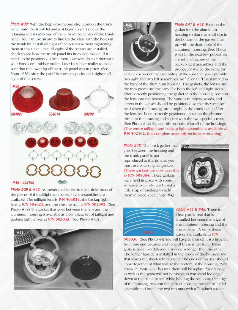
Photo #38: With the help of someone else, position the trunkpanel onto the trunk lid and just begin to start one of theretaining screws into one of the clips in the center of the trunkpanel. You can use an awl to line up the clips with the holes inthe trunk lid. Install all eight of the screws without tighteningthem at this time. Once all eight of the screws are installed,check to see how the trunk panel fits from side-to-side. If itneeds to be positioned a little more one way, do so either withyour hands or a rubber mallet. I used a rubber mallet to makesure that the lower lip of the trunk panel was in place. (SeePhoto #38) After the panel is correctly positioned, tighten alleight of the screws.
Photo #39 & #40: As mentioned earlier in the article, most ofthe pieces of the taillight and backup light assemblies areavailable. The taillight lens is P/N 504014, the backup lightlens is P/N 504021, and the chrome trim is P/N 502092. (SeePhoto #39) The gasket that goes between the lens and thealuminum housing is available as a complete set of taillight andparking light lenses as P/N 503033. (See Photo #40)
Photo #44 & #45: There is aclear plastic seal that isinstalled between the edge ofthe aluminum housing and thetrunk panel. A set of thesegaskets is available as P/N
505036. (See Photo 44) You will have to trim off just a little bitfrom one end because each one of these is too long. Thesegaskets have two different lips - one is longer then the other.The longer lip-side is installed in the inside of the housing andthat leaves the short-side exposed. The ends of this seal shouldcome together at what will he the bottom of the housing. (Seearrow in Photo 45) This way, there will be a place for drainageas well as the seam will not be visible as you stand lookingdown at the trunk panel. While holding the seal onto the edgeof the housing, position the correct housing into the trunk lidassembly and install the two cap-nuts with a 7/16-inch socket.
Photo #41 & #42: Position thegasket into the aluminumhousing so that the small slot inthe bottom of the gasket linesup with the drain hole of thealuminum housing. (See Photo#41) In the next few photos weare rebuilding one of thebackup light assemblies and theprocedure will be the same for
all four (or six) of the assemblies. Make sure that you assembletwo right and two left assemblies. An "R" or an "L" is stamped inthe back of the aluminum housing. The gaskets, the lenses andthe trim pieces are the same for both the left and right sides.After correctly positioning the gasket into the housing, positionthe lens into the housing. The various numbers, words, andletters in the lenses should be positioned so that they can beread when the housings are upright in the trunk panel. Afterthe lens has been correctly positioned, position the chrometrim into the housing and secure with the two special screws.(See Photo #42) Repeat this procedure for all of the housings.(The entire taillight and backup light assembly is available asP/N 502162, this complete assembly includes everything).
Photo #43: The black gasket thatgoes between the housing andthe trunk panel is notreproduced at this time so youmust use your original gaskets.(These gaskets are now availableas P/N 505064) These gasketswere held in place with someadhesive originally, but I used alittle strip of caulking to holdthem in place. (See Photo #43)
504021 504014 50209
#40 - 502162
#42
#43
#41 505036
#39

Remember that the backup light assemblies go toward theoutside of the trunk panel and the taillight assemblies gotoward the middle of the panel. Repeat this procedure for eachof the taillight and backup light assemblies.
#45
Photo #46: The upper trunk lid molding is available as P/N511028 and comes with clips. Now position the upper trunklid molding onto the trunk lid making sure that the six studs ofthe clips go through the correct holes. Using a 5/16-inch socket,install the six cap-nuts which secure the molding. After gettingall six of the cap-nuts started, start tightening them from themiddle toward the outside of the trunk lid. (See Photo #46)
Photo #47: If you really want to do a bang-up job in restoringthis trunk lid, you may want to consider installing a new trunklid emblem assembly which is P/N 501058. The trunk lid plasticassembly by itself is available as P/N 501067. If you are workingon an SS, you can install an "Impala SS" emblem on the rightside of the trunk lid and that is P/N 501093. (See photo #47)To re-install the cove molding back onto the car, first position
the cove molding and secure in place with a cap-nut. Positionthe correct taillight housing and secure with the two cap-nuts.Position the correct "hockey stick" molding and secure with thethree cap-nuts. Repeat this procedure for the other side of the1962.If you have installed all of these new parts and worked
carefully, you should now have a dynamite trunk lid to installback onto your 1962 Impala.
#46
#47