Building a Modern Computer From First Principlescyy/courses/introCS/17fall/...Elements of Computing...
72
Elements of Computing Systems, Nisan & Schocken, MIT Press, www.nand2tetris.org , Chapter 5: Computer Architecture slide 1 www.nand2tetris.org Building a Modern Computer From First Principles Computer Architecture
Transcript of Building a Modern Computer From First Principlescyy/courses/introCS/17fall/...Elements of Computing...
Elements of Computing Systems, Nisan & Schocken, MIT Press, www.nand2tetris.org , Chapter 5: Computer Architecture slide 1
www.nand2tetris.org
Building a Modern Computer From First Principles
Computer Architecture
Elements of Computing Systems, Nisan & Schocken, MIT Press, www.nand2tetris.org , Chapter 5: Computer Architecture slide 2
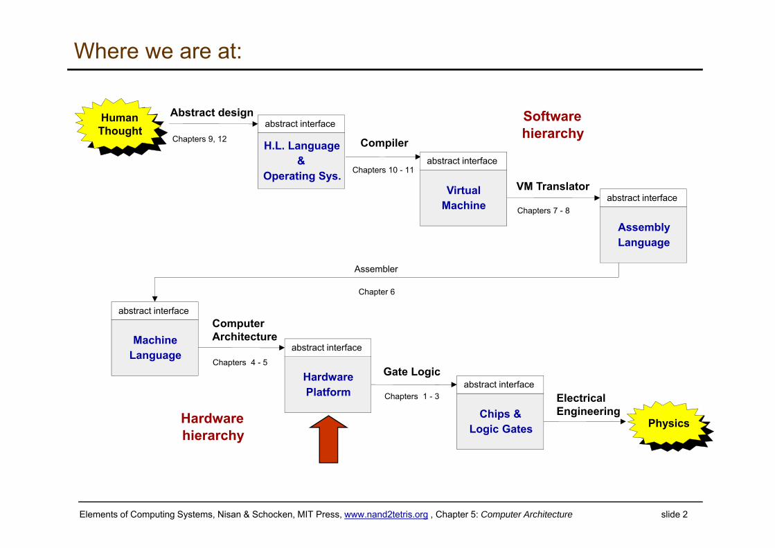
Where we are at:
Assembler
Chapter 6
H.L. Language&
Operating Sys.
abstract interface
Compiler
Chapters 10 - 11
VM Translator
Chapters 7 - 8
ComputerArchitecture
Chapters 4 - 5Gate Logic
Chapters 1 - 3 ElectricalEngineering
Physics
VirtualMachine
abstract interface
Softwarehierarchy
AssemblyLanguage
abstract interface
Hardwarehierarchy
MachineLanguage
abstract interface
HardwarePlatform
abstract interface
Chips &Logic Gates
abstract interface
HumanThought
Abstract design
Chapters 9, 12
Elements of Computing Systems, Nisan & Schocken, MIT Press, www.nand2tetris.org , Chapter 5: Computer Architecture slide 3
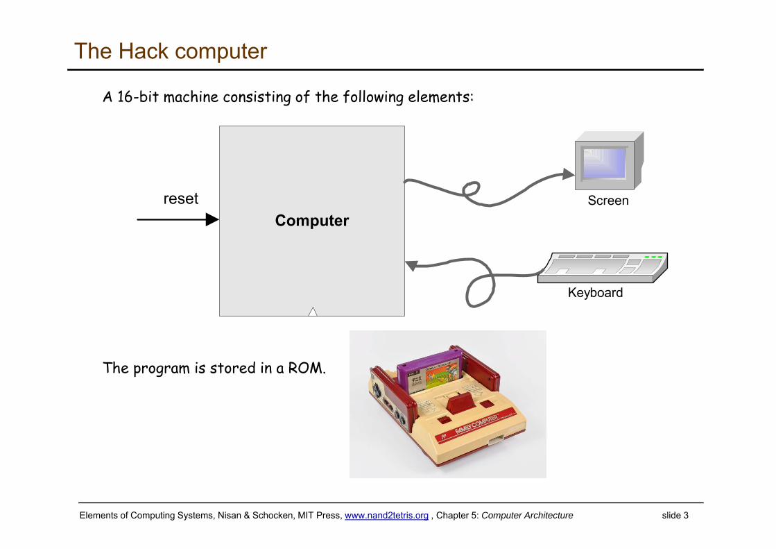
The Hack computer
A 16-bit machine consisting of the following elements:
The program is stored in a ROM.
Computerreset
Keyboard
Screen
Elements of Computing Systems, Nisan & Schocken, MIT Press, www.nand2tetris.org , Chapter 5: Computer Architecture slide 4
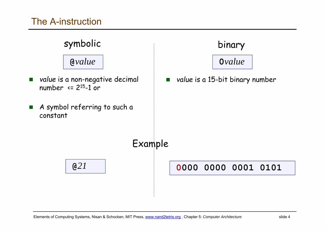
The A-instruction
@value
value is a non-negative decimal number <= 215-1 or
A symbol referring to such a constant
0value
value is a 15-bit binary number
symbolic binary
@21 0000 0000 0001 0101
Example
Elements of Computing Systems, Nisan & Schocken, MIT Press, www.nand2tetris.org , Chapter 5: Computer Architecture slide 5
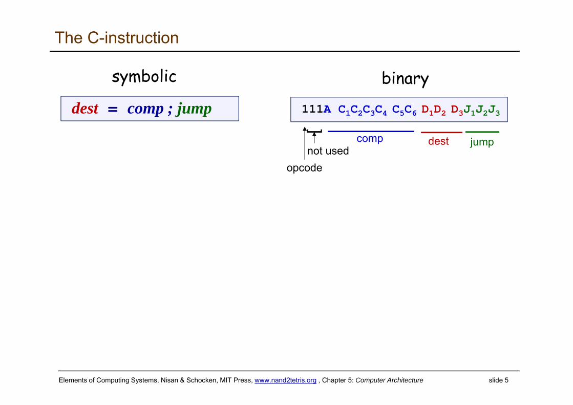
The C-instruction
dest = comp ; jump 111A C1C2C3C4 C5C6 D1D2 D3J1J2J3
symbolic binary
opcode
]
not usedcomp dest jump
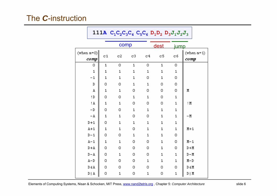
Elements of Computing Systems, Nisan & Schocken, MIT Press, www.nand2tetris.org , Chapter 5: Computer Architecture slide 6
The C-instruction111A C1C2C3C4 C5C6 D1D2 D3J1J2J3
comp dest jump
Elements of Computing Systems, Nisan & Schocken, MIT Press, www.nand2tetris.org , Chapter 5: Computer Architecture slide 7
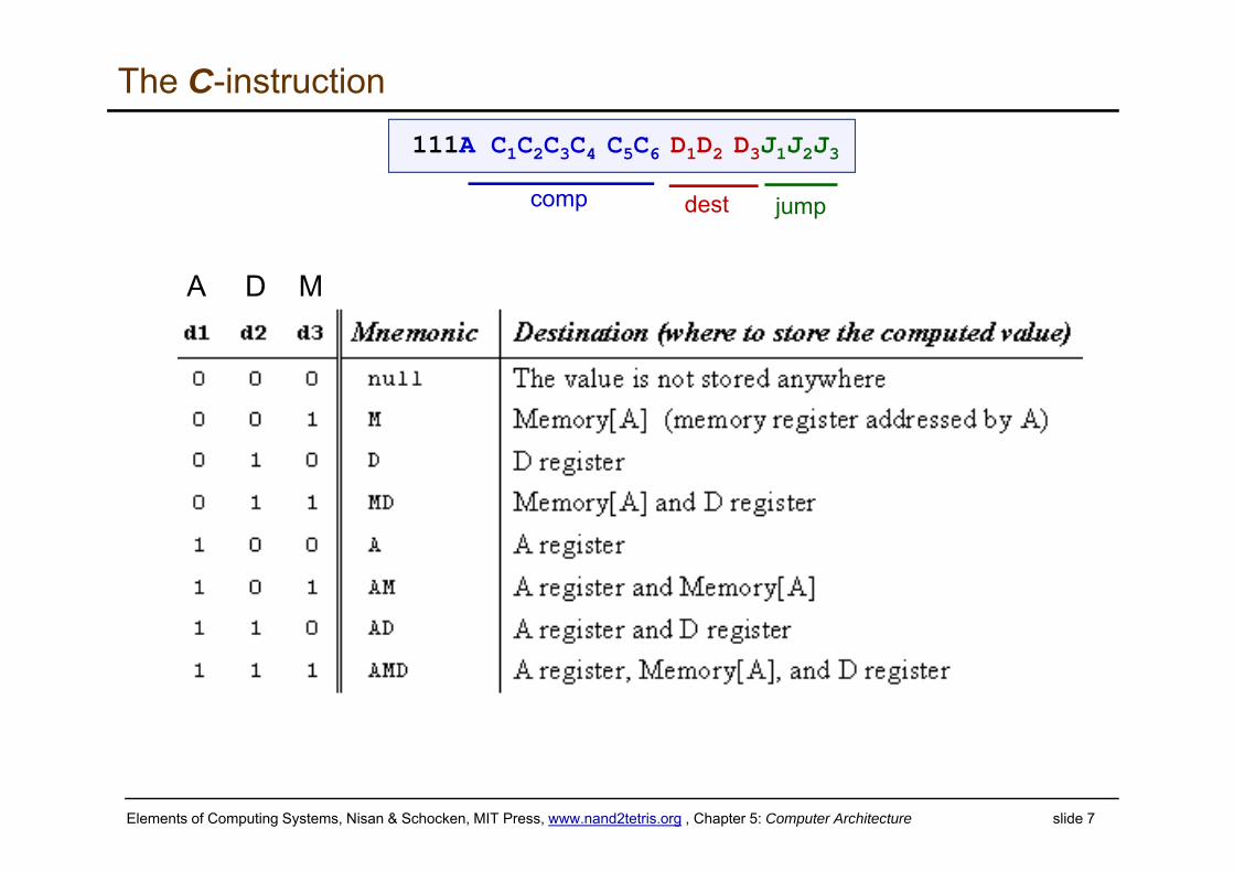
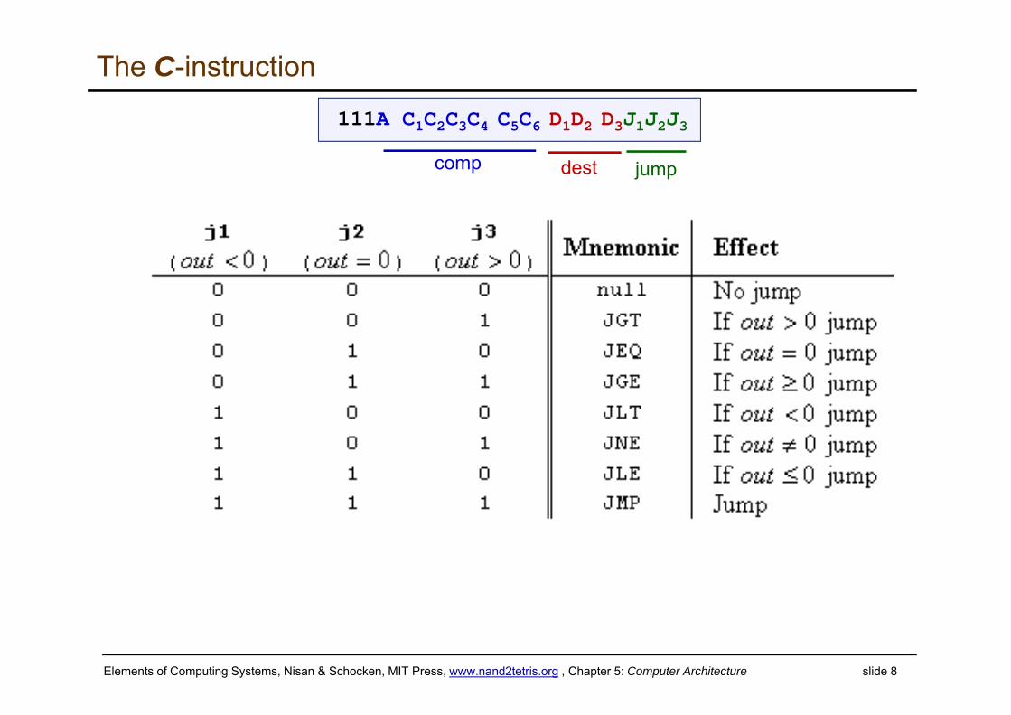
The C-instruction
A D M
111A C1C2C3C4 C5C6 D1D2 D3J1J2J3
comp dest jump
Elements of Computing Systems, Nisan & Schocken, MIT Press, www.nand2tetris.org , Chapter 5: Computer Architecture slide 8
The C-instruction111A C1C2C3C4 C5C6 D1D2 D3J1J2J3
comp dest jump
Elements of Computing Systems, Nisan & Schocken, MIT Press, www.nand2tetris.org , Chapter 5: Computer Architecture slide 9
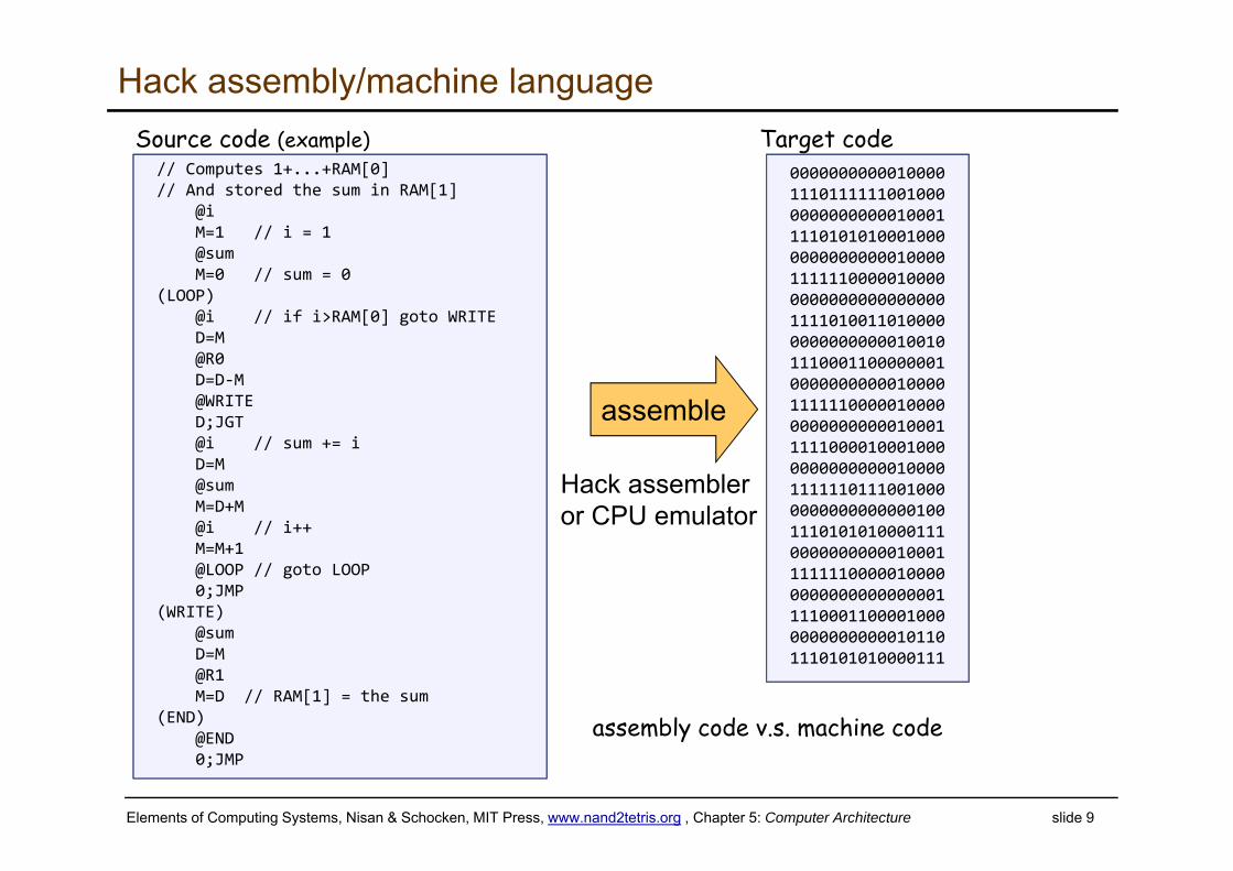
assembly code v.s. machine code
000000000001000011101111110010000000000000010001111010101000100000000000000100001111110000010000000000000000000011110100110100000000000000010010111000110000000100000000000100001111110000010000000000000001000111110000100010000000000000010000111111011100100000000000000001001110101010000111000000000001000111111100000100000000000000000001111000110000100000000000000101101110101010000111
Target code
assemble
Hack assembly/machine language
// Computes 1+...+RAM[0]// And stored the sum in RAM[1]
@iM=1 // i = 1 @sum M=0 // sum = 0
(LOOP)@i // if i>RAM[0] goto WRITED=M@R0D=D‐M@WRITE D;JGT@i // sum += iD=M@sumM=D+M@i // i++M=M+1 @LOOP // goto LOOP0;JMP
(WRITE)@sumD=M@R1M=D // RAM[1] = the sum
(END)@END0;JMP
Source code (example)
Hack assembler or CPU emulator
Elements of Computing Systems, Nisan & Schocken, MIT Press, www.nand2tetris.org , Chapter 5: Computer Architecture slide 10
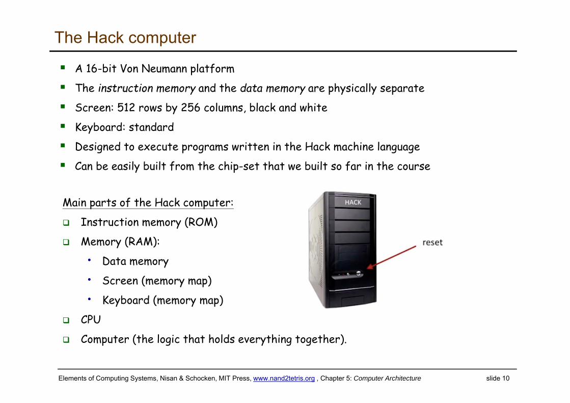
The Hack computer
Main parts of the Hack computer:
Instruction memory (ROM)
Memory (RAM):
• Data memory
• Screen (memory map)
• Keyboard (memory map)
CPU
Computer (the logic that holds everything together).
A 16-bit Von Neumann platform
The instruction memory and the data memory are physically separate
Screen: 512 rows by 256 columns, black and white
Keyboard: standard
Designed to execute programs written in the Hack machine language
Can be easily built from the chip-set that we built so far in the course
Elements of Computing Systems, Nisan & Schocken, MIT Press, www.nand2tetris.org , Chapter 5: Computer Architecture slide 11
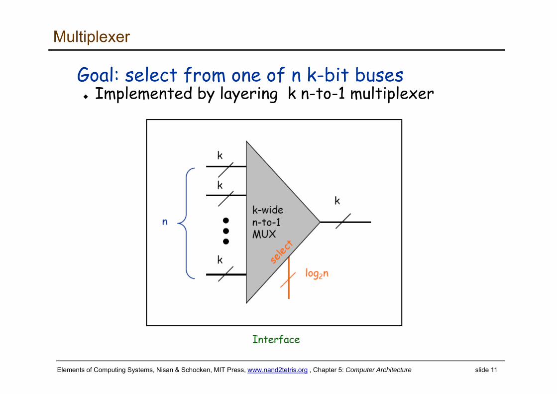
Multiplexer
Goal: select from one of n k-bit buses Implemented by layering k n-to-1 multiplexer
Elements of Computing Systems, Nisan & Schocken, MIT Press, www.nand2tetris.org , Chapter 5: Computer Architecture slide 12
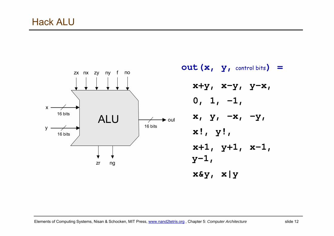
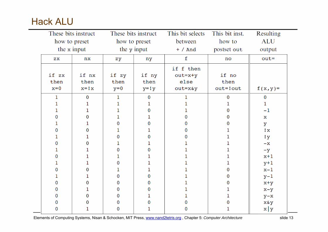
Hack ALU
zx no
zr
nx zy ny f
ALU
ng
16 bits
16 bits
x
y 16 bitsout
out(x, y, control bits) =
x+y, x-y, y–x,
0, 1, -1,
x, y, -x, -y,
x!, y!,
x+1, y+1, x-1, y-1,
x&y, x|y
Elements of Computing Systems, Nisan & Schocken, MIT Press, www.nand2tetris.org , Chapter 5: Computer Architecture slide 13
Hack ALU
Elements of Computing Systems, Nisan & Schocken, MIT Press, www.nand2tetris.org , Chapter 5: Computer Architecture slide 1414
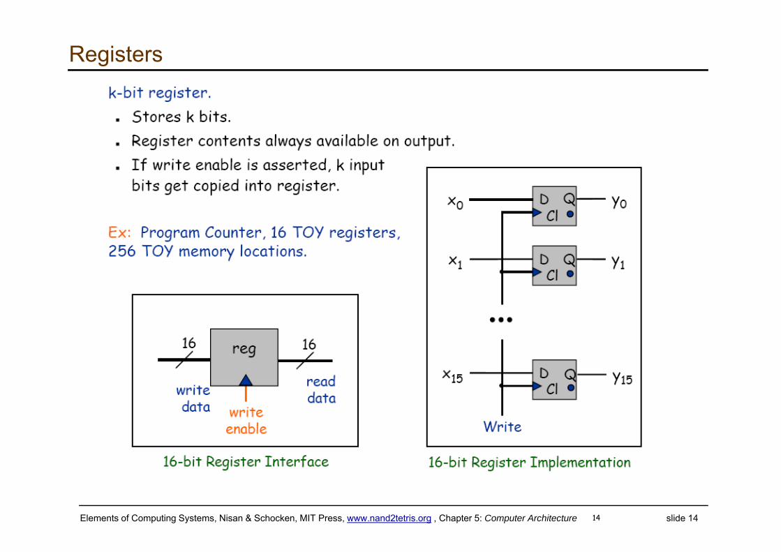
Registers
Elements of Computing Systems, Nisan & Schocken, MIT Press, www.nand2tetris.org , Chapter 5: Computer Architecture slide 15
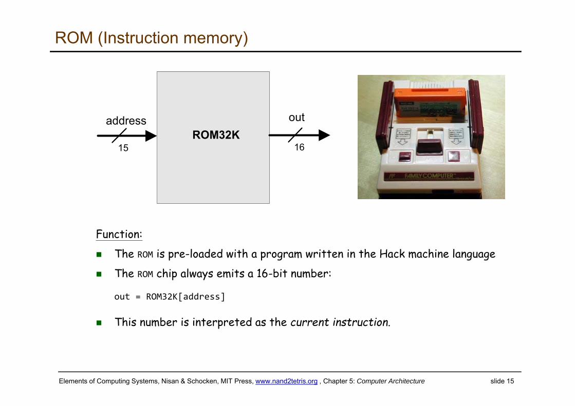
ROM (Instruction memory)
out
15 16
addressROM32K
Function:
The ROM is pre-loaded with a program written in the Hack machine language
The ROM chip always emits a 16-bit number:
out = ROM32K[address]
This number is interpreted as the current instruction.
Elements of Computing Systems, Nisan & Schocken, MIT Press, www.nand2tetris.org , Chapter 5: Computer Architecture slide 16
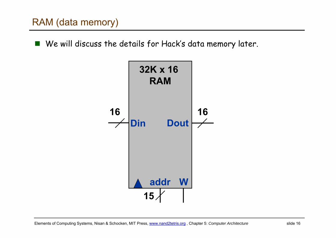
RAM (data memory)
We will discuss the details for Hack’s data memory later.
32K x 16RAM
W
Din
addr
Dout16 16
15
Elements of Computing Systems, Nisan & Schocken, MIT Press, www.nand2tetris.org , Chapter 5: Computer Architecture slide 1717
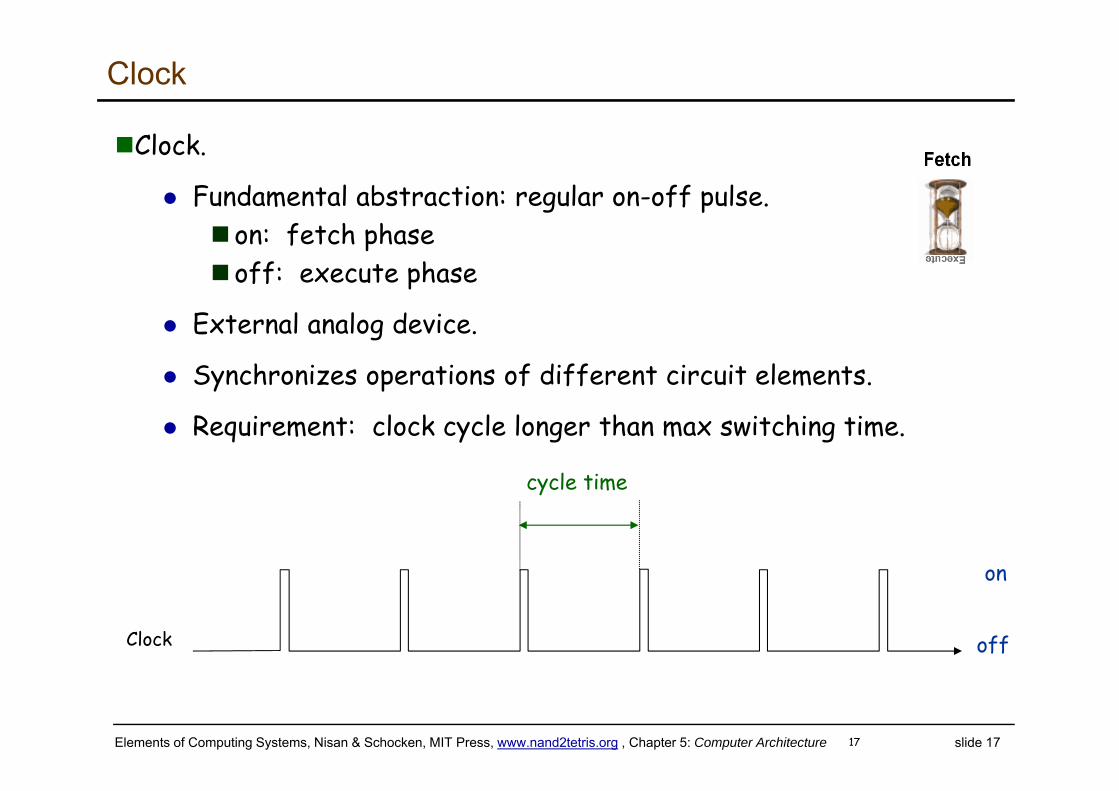
Clock
Clock.
Fundamental abstraction: regular on-off pulse.on: fetch phaseoff: execute phase
External analog device.
Synchronizes operations of different circuit elements.
Requirement: clock cycle longer than max switching time.
cycle time
Clock
on
off
Elements of Computing Systems, Nisan & Schocken, MIT Press, www.nand2tetris.org , Chapter 5: Computer Architecture slide 18
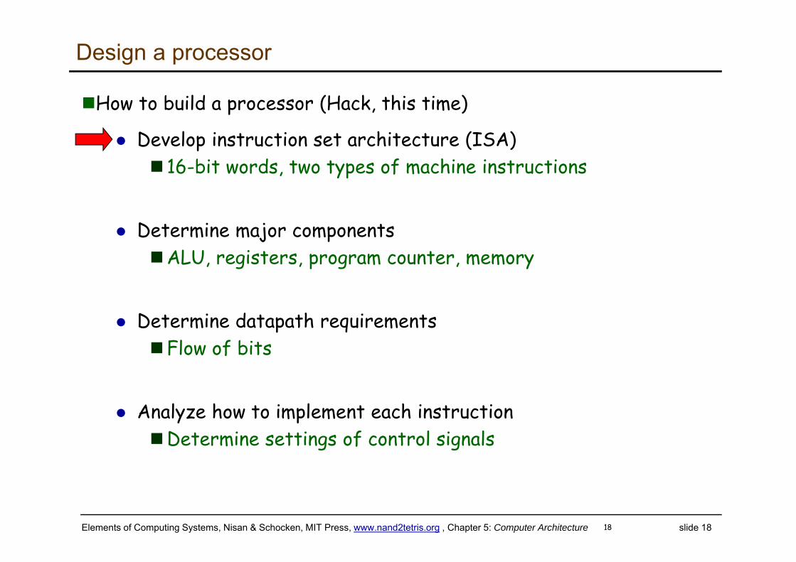
Design a processor
How to build a processor (Hack, this time)
Develop instruction set architecture (ISA) 16-bit words, two types of machine instructions
Determine major componentsALU, registers, program counter, memory
Determine datapath requirementsFlow of bits
Analyze how to implement each instructionDetermine settings of control signals
18
Elements of Computing Systems, Nisan & Schocken, MIT Press, www.nand2tetris.org , Chapter 5: Computer Architecture slide 19
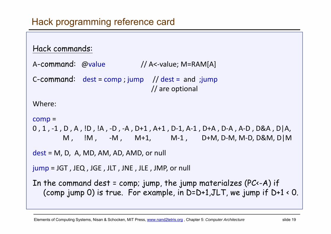
Hack programming reference card
Hack commands:
A-command: @value // A<‐value; M=RAM[A]
C-command: dest = comp ; jump // dest = and ;jump// are optional
Where:
comp = 0 , 1 , ‐1 , D , A , !D , !A , ‐D , ‐A , D+1 , A+1 , D‐1, A‐1 , D+A , D‐A , A‐D , D&A , D|A,
M , !M , ‐M , M+1, M‐1 , D+M, D‐M, M‐D, D&M, D|M
dest = M, D, A, MD, AM, AD, AMD, or null
jump = JGT , JEQ , JGE , JLT , JNE , JLE , JMP, or null
In the command dest = comp; jump, the jump materialzes (PC<-A) if (comp jump 0) is true. For example, in D=D+1,JLT, we jump if D+1 < 0.
Elements of Computing Systems, Nisan & Schocken, MIT Press, www.nand2tetris.org , Chapter 5: Computer Architecture slide 20
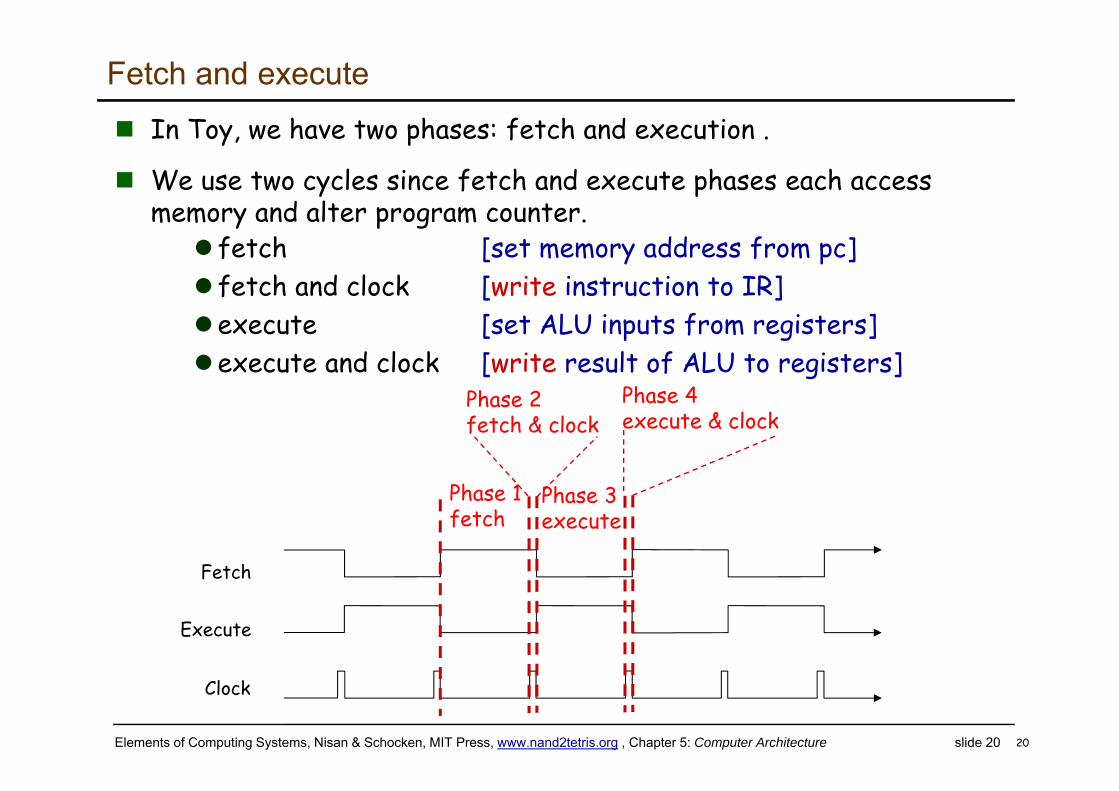
Fetch and execute In Toy, we have two phases: fetch and execution .
We use two cycles since fetch and execute phases each access memory and alter program counter.
20
Fetch
Clock
Execute
Fetch
Phase 1fetch
Phase 3execute
Phase 2fetch & clock
Phase 4execute & clock
fetch [set memory address from pc] fetch and clock [write instruction to IR]execute [set ALU inputs from registers]execute and clock [write result of ALU to registers]
21
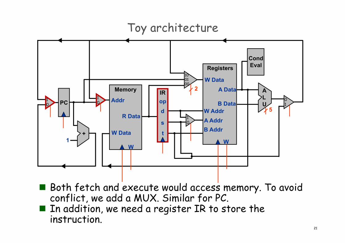
Toy architecture
PC
Registers
W
W DataA Data
B DataW AddrA AddrB Addr+
1
Memory
W
W Data
Addr
R Data
IRopd
s
t
CondEval
ALU
2
5
10
10
01
10
100100
Both fetch and execute would access memory. To avoid conflict, we add a MUX. Similar for PC.
In addition, we need a register IR to store the instruction.
Elements of Computing Systems, Nisan & Schocken, MIT Press, www.nand2tetris.org , Chapter 5: Computer Architecture slide 22
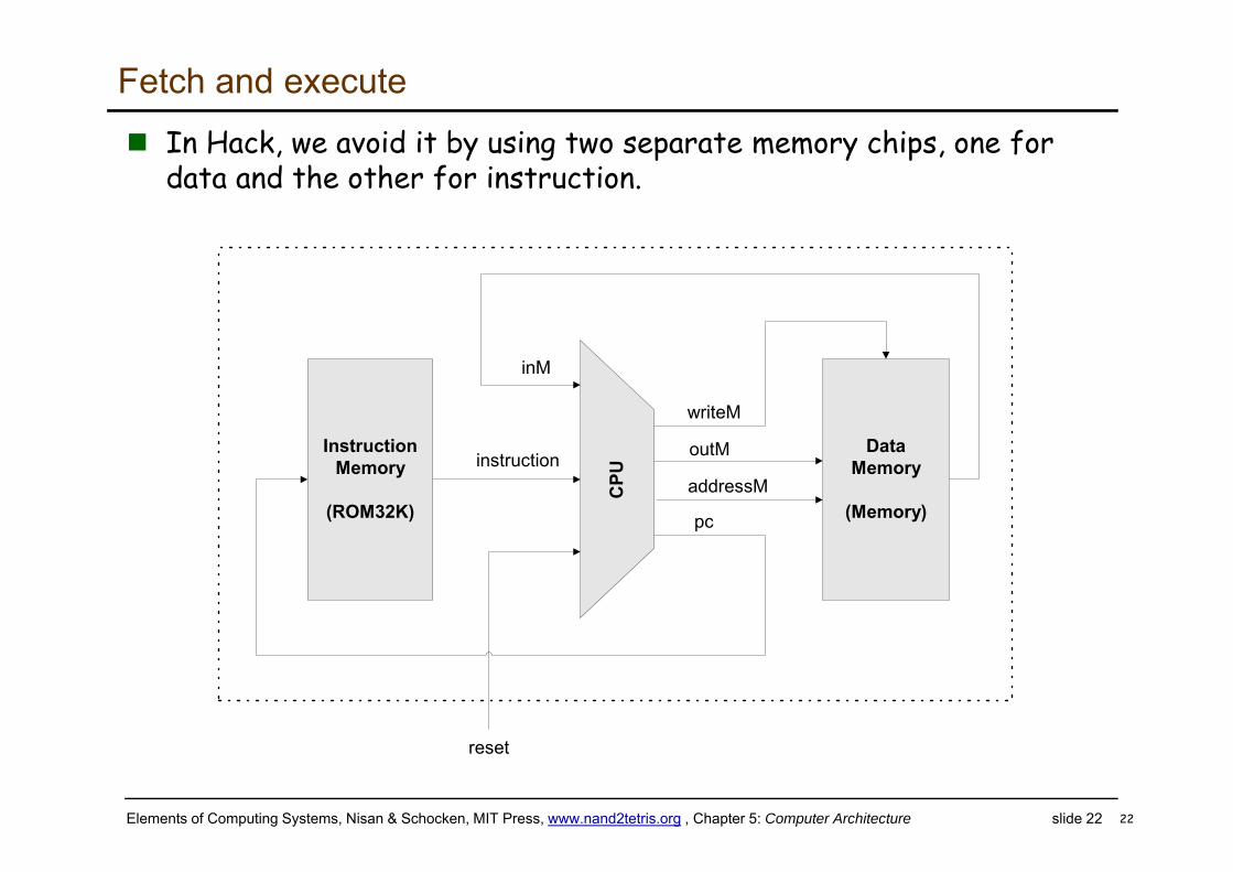
Fetch and execute In Hack, we avoid it by using two separate memory chips, one for
data and the other for instruction.
22
DataMemory
(Memory)
instruction
CPU
InstructionMemory
(ROM32K)
inM
outM
addressM
writeM
pc
reset
Elements of Computing Systems, Nisan & Schocken, MIT Press, www.nand2tetris.org , Chapter 5: Computer Architecture slide 23
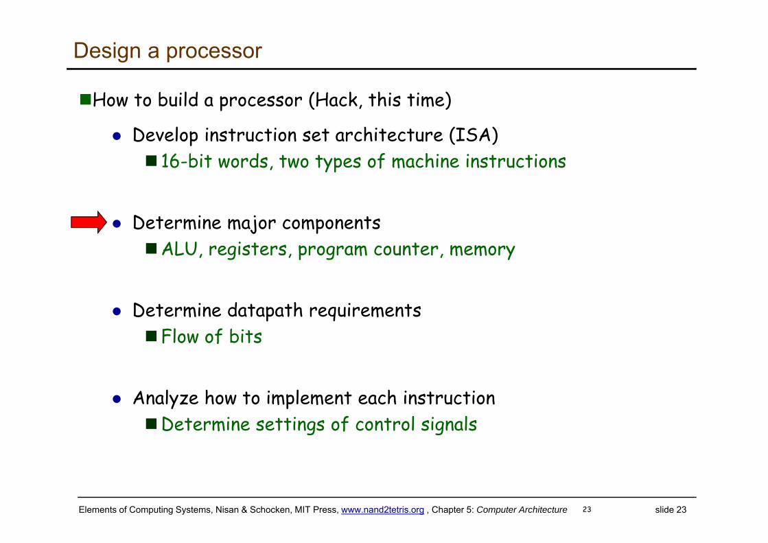
Design a processor
How to build a processor (Hack, this time)
Develop instruction set architecture (ISA) 16-bit words, two types of machine instructions
Determine major componentsALU, registers, program counter, memory
Determine datapath requirementsFlow of bits
Analyze how to implement each instructionDetermine settings of control signals
23
Elements of Computing Systems, Nisan & Schocken, MIT Press, www.nand2tetris.org , Chapter 5: Computer Architecture slide 24
Program counter
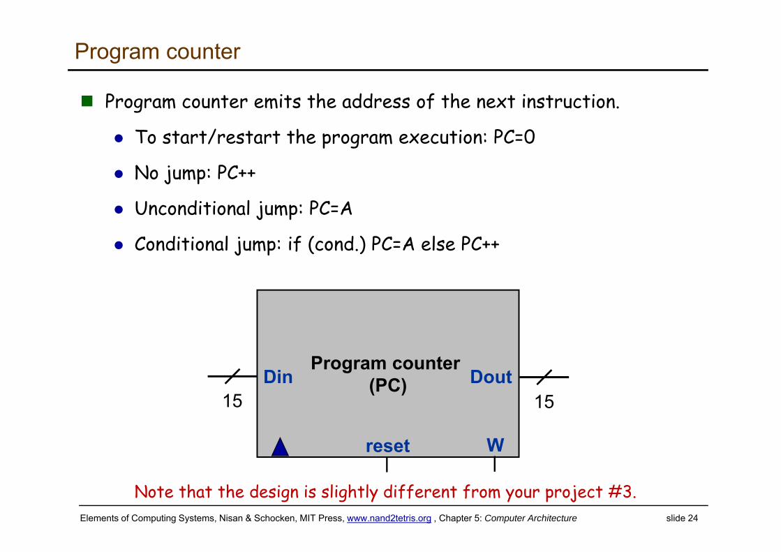
Program counter emits the address of the next instruction.
To start/restart the program execution: PC=0
No jump: PC++
Unconditional jump: PC=A
Conditional jump: if (cond.) PC=A else PC++
Program counter (PC)
reset W
Din Dout15 15
Note that the design is slightly different from your project #3.
Elements of Computing Systems, Nisan & Schocken, MIT Press, www.nand2tetris.org , Chapter 5: Computer Architecture slide 25
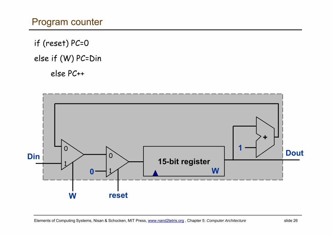
Program counter
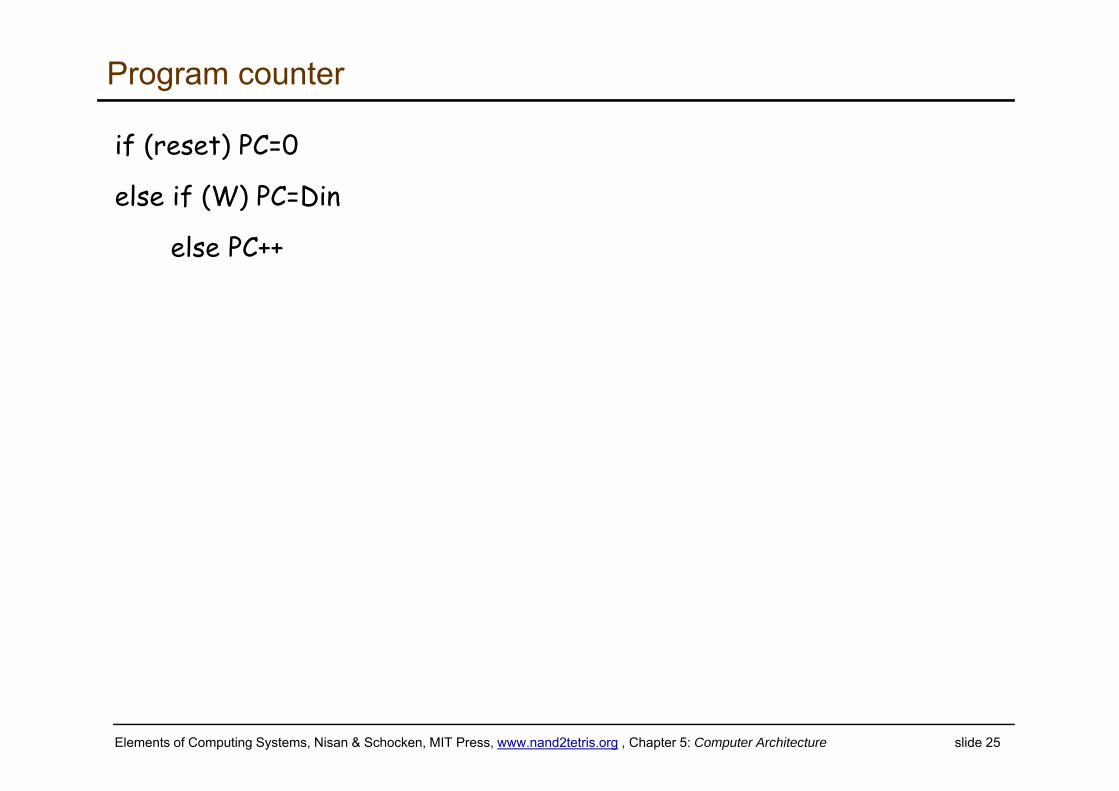
if (reset) PC=0
else if (W) PC=Din
else PC++
Elements of Computing Systems, Nisan & Schocken, MIT Press, www.nand2tetris.org , Chapter 5: Computer Architecture slide 26
Program counter
if (reset) PC=0
else if (W) PC=Din
else PC++
0
115-bit register
W
+10
10
resetW
Din Dout
Elements of Computing Systems, Nisan & Schocken, MIT Press, www.nand2tetris.org , Chapter 5: Computer Architecture slide 27
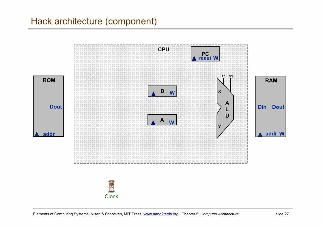
Hack architecture (component)
ALU
PC
RAM
W
Din
addr
Dout
ROM
addr
Dout
A W
D W
W
x
y
zr ng
CPUreset
Clock
Elements of Computing Systems, Nisan & Schocken, MIT Press, www.nand2tetris.org , Chapter 5: Computer Architecture slide 28
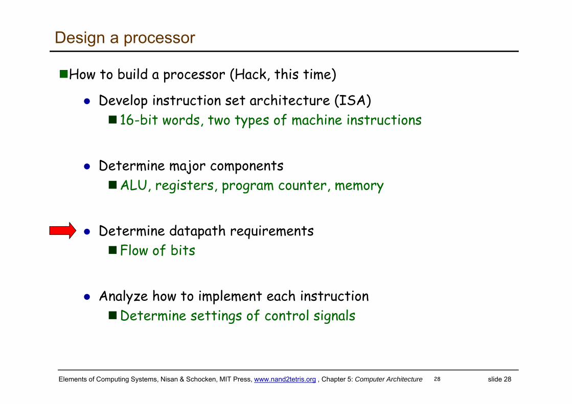
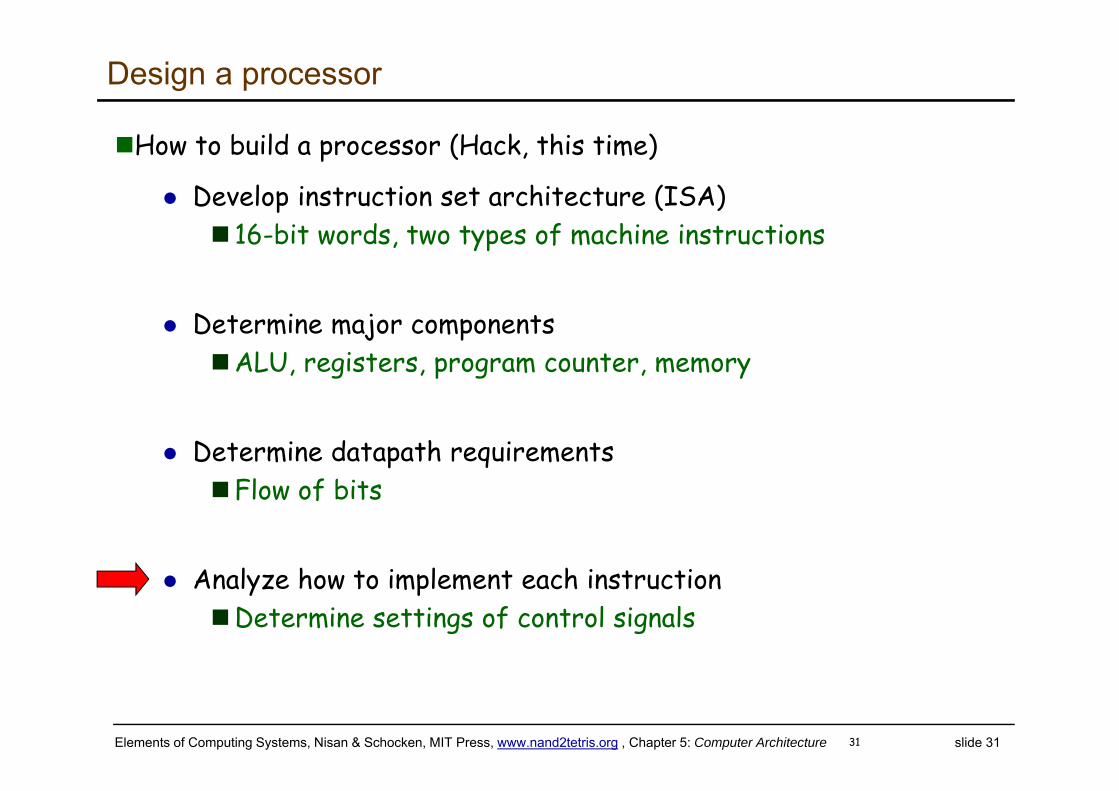
Design a processor
How to build a processor (Hack, this time)
Develop instruction set architecture (ISA) 16-bit words, two types of machine instructions
Determine major componentsALU, registers, program counter, memory
Determine datapath requirementsFlow of bits
Analyze how to implement each instructionDetermine settings of control signals
28
Elements of Computing Systems, Nisan & Schocken, MIT Press, www.nand2tetris.org , Chapter 5: Computer Architecture slide 29
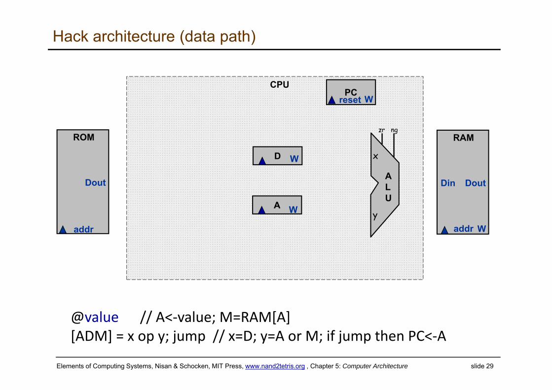
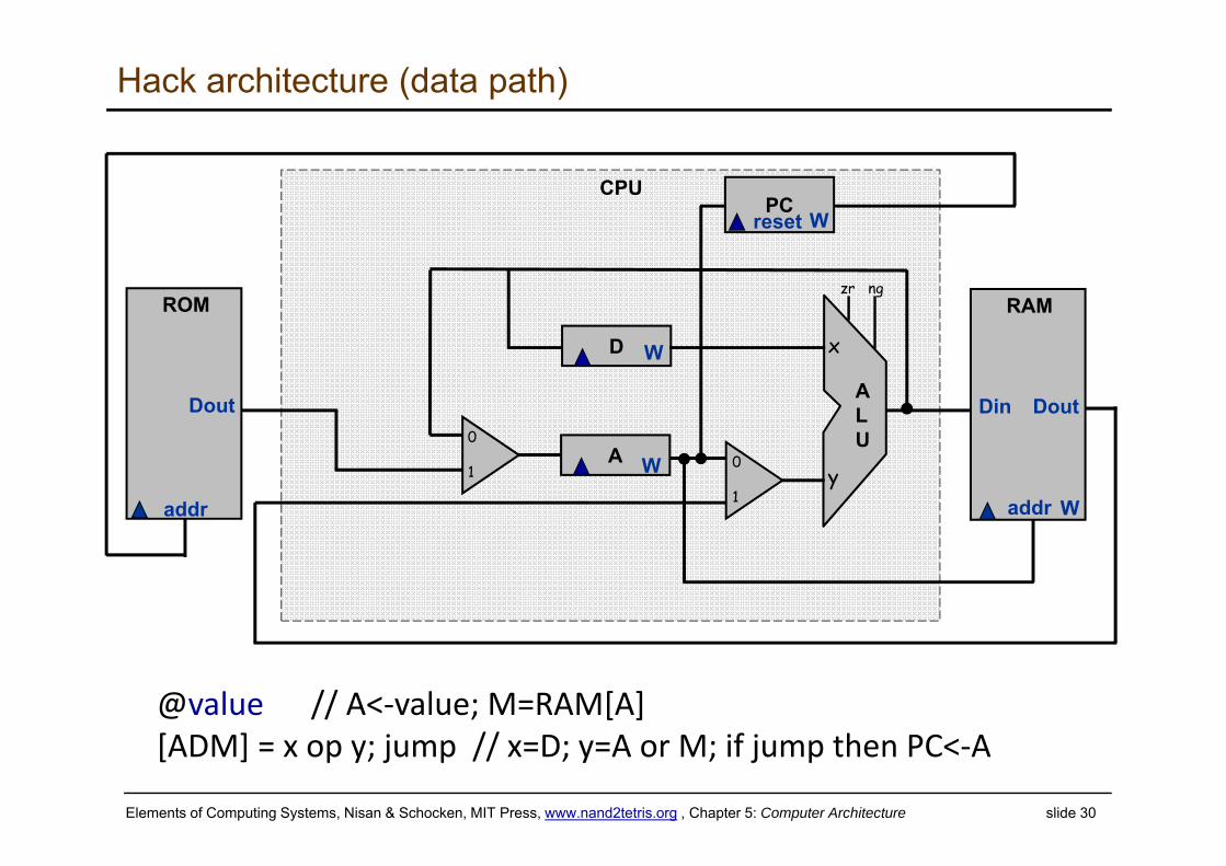
Hack architecture (data path)
ALU
PC
RAM
W
Din
addr
Dout
ROM
addr
Dout
A W
D W
W
x
y
zr ng
CPUreset
@value // A<‐value; M=RAM[A][ADM] = x op y; jump // x=D; y=A or M; if jump then PC<‐A
Elements of Computing Systems, Nisan & Schocken, MIT Press, www.nand2tetris.org , Chapter 5: Computer Architecture slide 30
Hack architecture (data path)
ALU
PC
RAM
W
Din
addr
Dout
ROM
addr
Dout
A W
D W
W
0
1
0
1
x
y
zr ng
CPU
@value // A<‐value; M=RAM[A][ADM] = x op y; jump // x=D; y=A or M; if jump then PC<‐A
reset
Elements of Computing Systems, Nisan & Schocken, MIT Press, www.nand2tetris.org , Chapter 5: Computer Architecture slide 31
Design a processor
How to build a processor (Hack, this time)
Develop instruction set architecture (ISA) 16-bit words, two types of machine instructions
Determine major componentsALU, registers, program counter, memory
Determine datapath requirementsFlow of bits
Analyze how to implement each instructionDetermine settings of control signals
31
Elements of Computing Systems, Nisan & Schocken, MIT Press, www.nand2tetris.org , Chapter 5: Computer Architecture slide 32
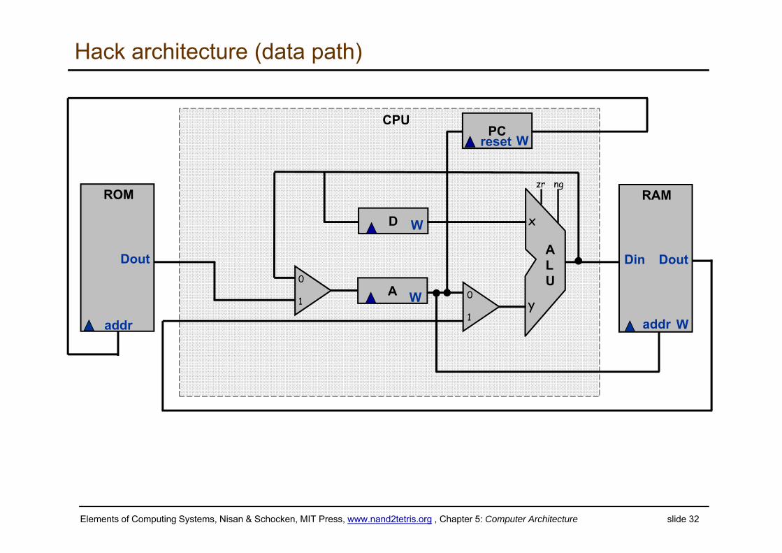
Hack architecture (data path)
ALU
PC
RAM
W
Din
addr
Dout
ROM
addr
Dout
A W
D W
W
0
1
0
1
x
y
zr ng
CPUreset
Elements of Computing Systems, Nisan & Schocken, MIT Press, www.nand2tetris.org , Chapter 5: Computer Architecture slide 33
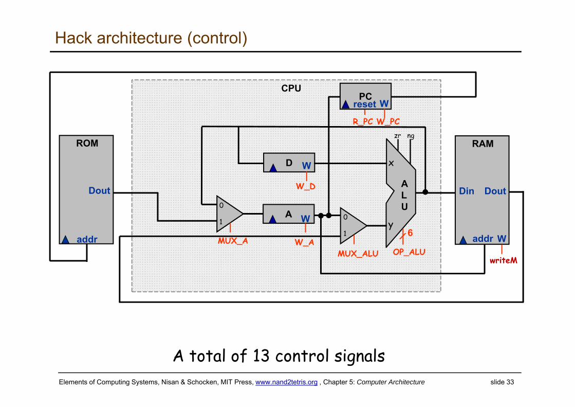
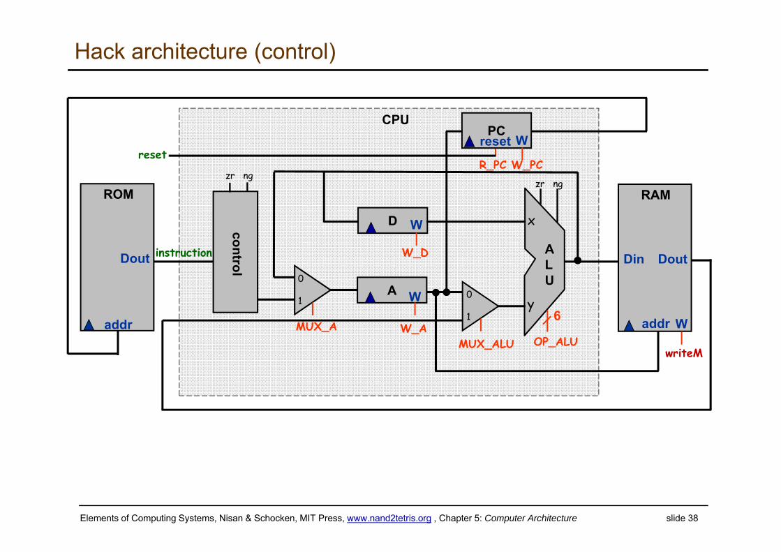
Hack architecture (control)
ALU
PC
RAM
W
Din
addr
Dout
ROM
addr
Dout
A W
D W
W
0
1
0
1
x
y
zr ng
CPUreset
MUX_A W_AMUX_ALU OP_ALU
6
W_PC
writeM
R_PC
W_D
A total of 13 control signals
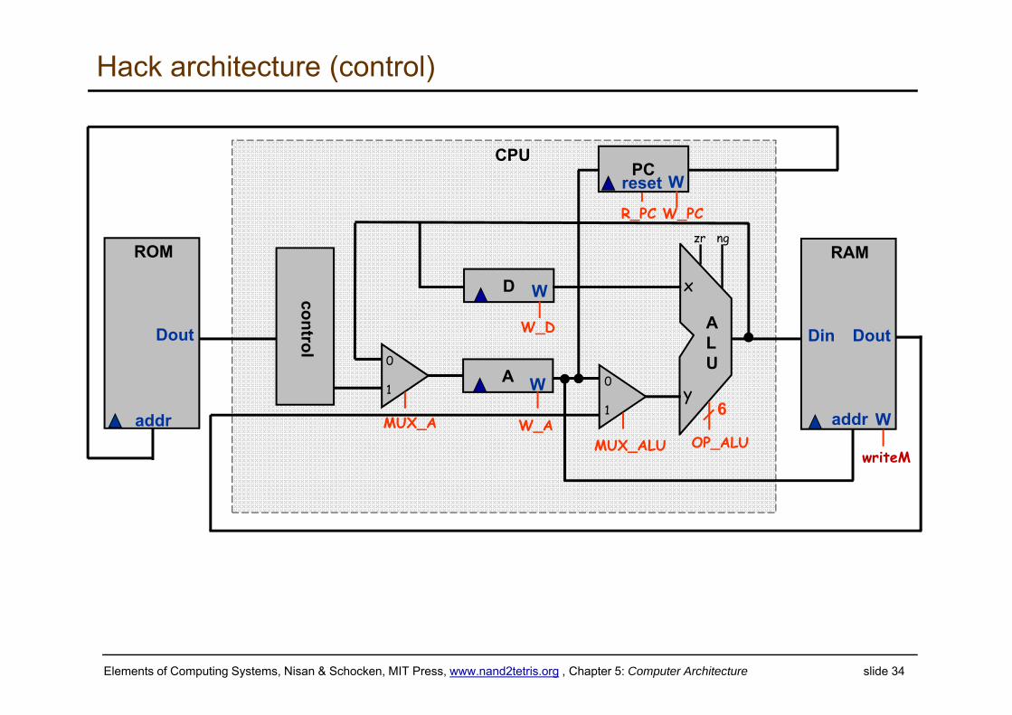
Elements of Computing Systems, Nisan & Schocken, MIT Press, www.nand2tetris.org , Chapter 5: Computer Architecture slide 34
Hack architecture (control)
ALU
PC
RAM
W
Din
addr
Dout
ROM
addr
Dout
A W
D W
W
0
1
0
1
x
y
zr ng
CPUreset
MUX_A W_AMUX_ALU OP_ALU
6
W_PC
writeM
R_PC
W_D
control
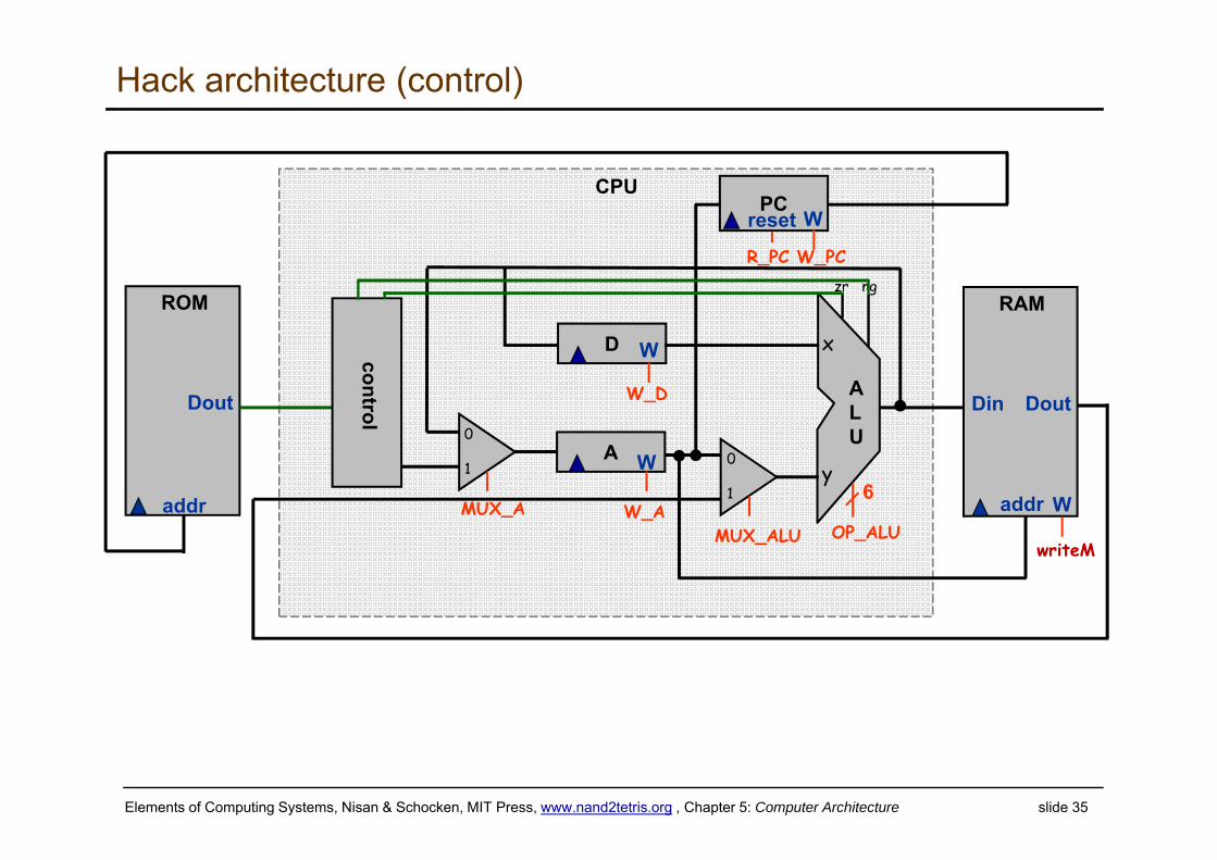
Elements of Computing Systems, Nisan & Schocken, MIT Press, www.nand2tetris.org , Chapter 5: Computer Architecture slide 35
Hack architecture (control)
ALU
PC
RAM
W
Din
addr
Dout
ROM
addr
Dout
A W
D W
W
0
1
0
1
x
y
zr ng
CPUreset
MUX_A W_AMUX_ALU OP_ALU
6
W_PC
writeM
R_PC
W_D
control
Elements of Computing Systems, Nisan & Schocken, MIT Press, www.nand2tetris.org , Chapter 5: Computer Architecture slide 36
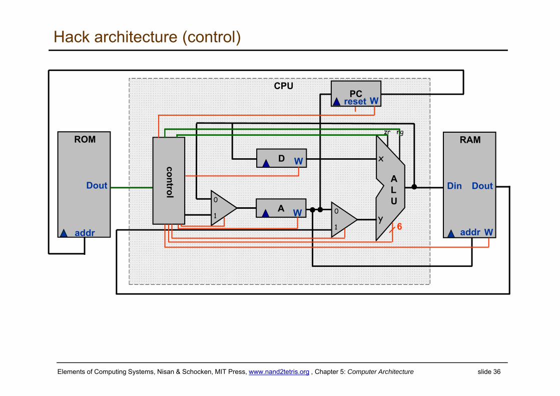
Hack architecture (control)
ALU
PC
RAM
W
Din
addr
Dout
ROM
addr
Dout
A W
D W
W
0
1
0
1
x
y
zr ng
CPUreset
6
control
Elements of Computing Systems, Nisan & Schocken, MIT Press, www.nand2tetris.org , Chapter 5: Computer Architecture slide 37
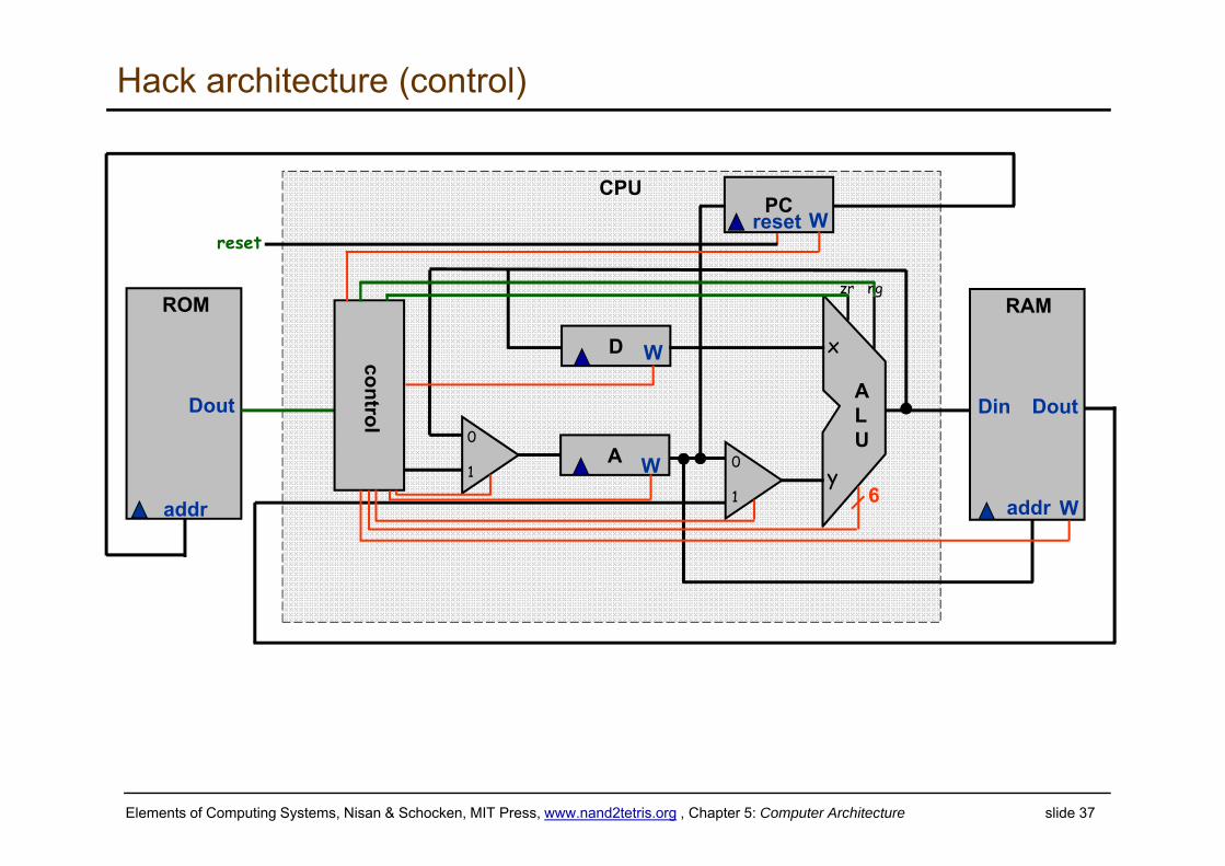
Hack architecture (control)
ALU
PC
RAM
W
Din
addr
Dout
ROM
addr
Dout
A W
D W
W
0
1
0
1
x
y
zr ng
CPUreset
6
control
reset
Elements of Computing Systems, Nisan & Schocken, MIT Press, www.nand2tetris.org , Chapter 5: Computer Architecture slide 38
Hack architecture (control)
ALU
PC
RAM
W
Din
addr
Dout
ROM
addr
Dout
A W
D W
W
0
1
0
1
x
y
zr ng
CPUreset
MUX_A W_AMUX_ALU OP_ALU
6
W_PC
writeM
R_PC
W_D
control
reset
zr ng
instruction
Elements of Computing Systems, Nisan & Schocken, MIT Press, www.nand2tetris.org , Chapter 5: Computer Architecture slide 39
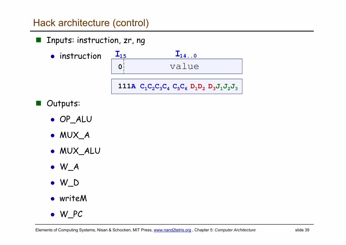
Hack architecture (control) Inputs: instruction, zr, ng
instruction
Outputs:
OP_ALU
MUX_A
MUX_ALU
W_A
W_D
writeM
W_PC
111A C1C2C3C4 C5C6 D1D2 D3J1J2J3
0 value I15 I14..0
Elements of Computing Systems, Nisan & Schocken, MIT Press, www.nand2tetris.org , Chapter 5: Computer Architecture slide 40
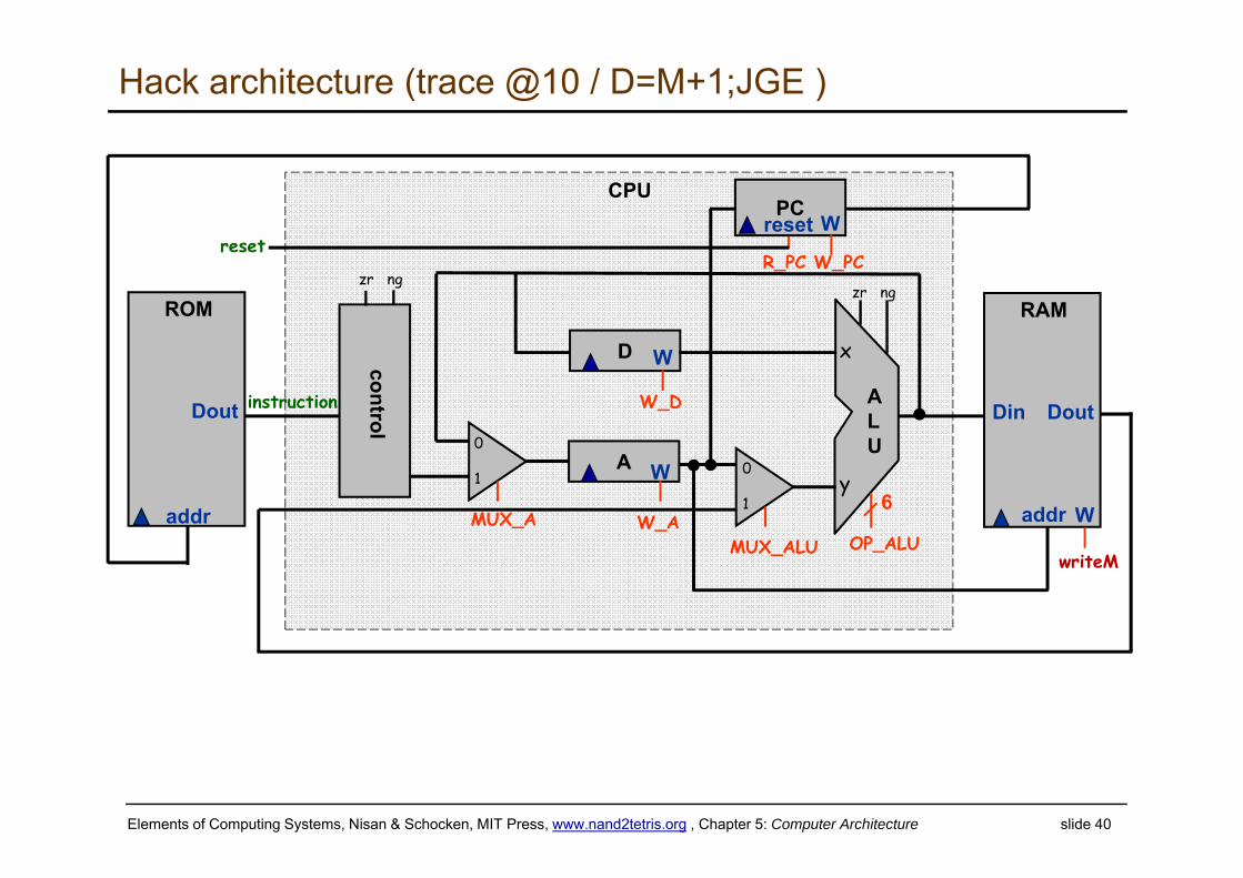
Hack architecture (trace @10 / D=M+1;JGE )
ALU
PC
RAM
W
Din
addr
Dout
ROM
addr
Dout
A W
D W
W
0
1
0
1
x
y
zr ng
CPUreset
MUX_A W_AMUX_ALU OP_ALU
6
W_PC
writeM
R_PC
W_D
control
reset
zr ng
instruction
Elements of Computing Systems, Nisan & Schocken, MIT Press, www.nand2tetris.org , Chapter 5: Computer Architecture slide 41
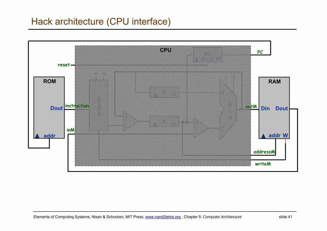
Hack architecture (CPU interface)
ALU
PC
RAM
W
Din
addr
Dout
ROM
addr
Dout
A W
D Wcontrol
W
0
1
0
1
x
y
zr ng
inM
reset
writeM
PC
addressM
reset
zr ng
outMinstruction
CPU
Elements of Computing Systems, Nisan & Schocken, MIT Press, www.nand2tetris.org , Chapter 5: Computer Architecture slide 42
Hack CPU
instruction
inM
16
1
15
15
16 outM
16
writeM
addressM
pcreset
1
CPU
to datamemory
to instructionmemory
fromdata memory
frominstruction
memory
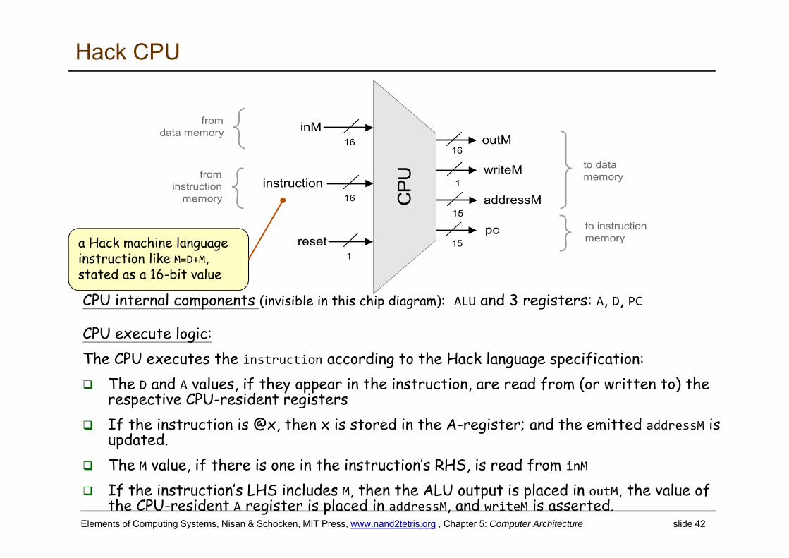
CPU internal components (invisible in this chip diagram): ALU and 3 registers: A, D, PC
CPU execute logic:The CPU executes the instruction according to the Hack language specification: The D and A values, if they appear in the instruction, are read from (or written to) the
respective CPU-resident registers If the instruction is @x, then x is stored in the A-register; and the emitted addressM is
updated. The M value, if there is one in the instruction’s RHS, is read from inM If the instruction’s LHS includes M, then the ALU output is placed in outM, the value of
the CPU-resident A register is placed in addressM, and writeM is asserted.
a Hack machine language instruction like M=D+M, stated as a 16-bit value
Elements of Computing Systems, Nisan & Schocken, MIT Press, www.nand2tetris.org , Chapter 5: Computer Architecture slide 43
Hack CPU
instruction
inM
16
1
15
15
16 outM
16
writeM
addressM
pcreset
1
CPU
to datamemory
to instructionmemory
fromdata memory
frominstruction
memory
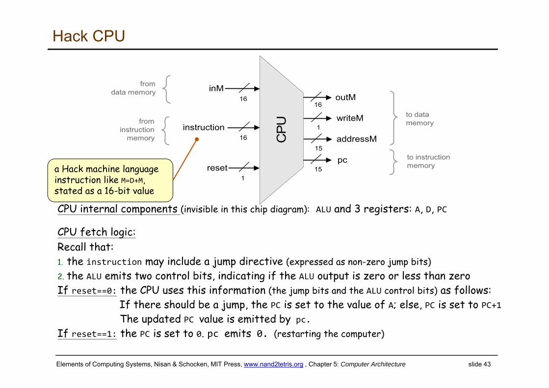
CPU internal components (invisible in this chip diagram): ALU and 3 registers: A, D, PC
CPU fetch logic:Recall that:1. the instruction may include a jump directive (expressed as non-zero jump bits)2. the ALU emits two control bits, indicating if the ALU output is zero or less than zeroIf reset==0: the CPU uses this information (the jump bits and the ALU control bits) as follows:
If there should be a jump, the PC is set to the value of A; else, PC is set to PC+1The updated PC value is emitted by pc.
If reset==1: the PC is set to 0. pc emits 0. (restarting the computer)
a Hack machine language instruction like M=D+M, stated as a 16-bit value
Elements of Computing Systems, Nisan & Schocken, MIT Press, www.nand2tetris.org , Chapter 5: Computer Architecture slide 44
Control (focus on the yellow chips only)
ALU
Mux
D
A/M
a-bit
D register
A registerA
MRAM
(selected register)
ROM
(selected register)
PCInstruction
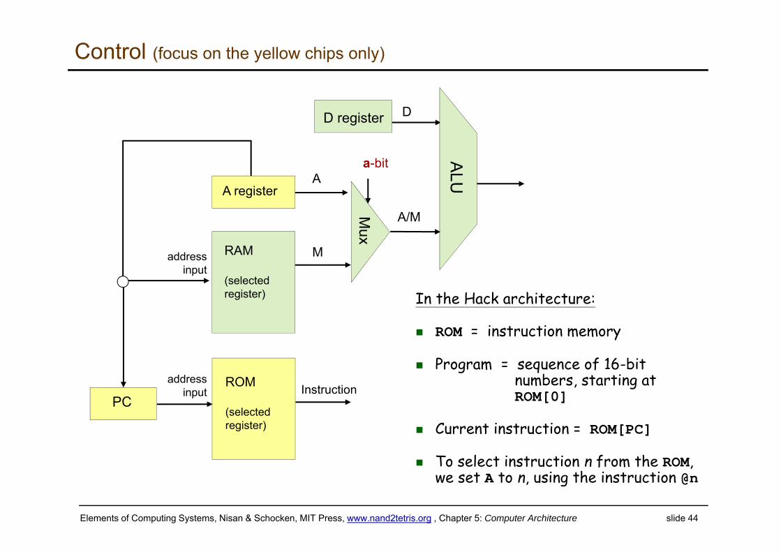
In the Hack architecture:
ROM = instruction memory
Program = sequence of 16-bitnumbers, starting atROM[0]
Current instruction = ROM[PC]
To select instruction n from the ROM, we set A to n, using the instruction @n
addressinput
addressinput
Elements of Computing Systems, Nisan & Schocken, MIT Press, www.nand2tetris.org , Chapter 5: Computer Architecture slide 45
Side note (focus on the yellow chip parts only)
ALU
Mux
D
A/M
a-bit
D register
A registerA
MRAM
(selected register)
ROM
(selected register)
PCInstruction
addressinput
addressinput
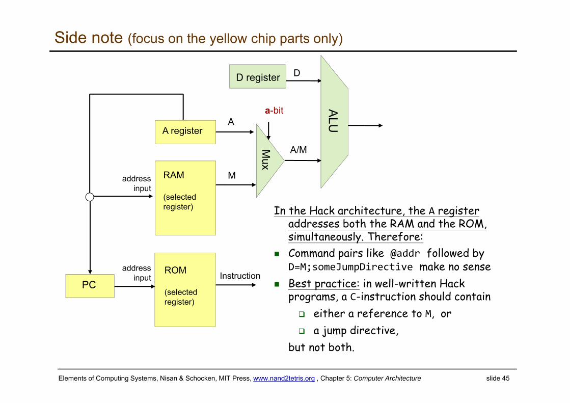
In the Hack architecture, the A register addresses both the RAM and the ROM, simultaneously. Therefore:
Command pairs like @addr followed by D=M;someJumpDirective make no sense
Best practice: in well-written Hack programs, a C-instruction should contain either a reference to M, or a jump directive,
but not both.
Elements of Computing Systems, Nisan & Schocken, MIT Press, www.nand2tetris.org , Chapter 5: Computer Architecture slide 46
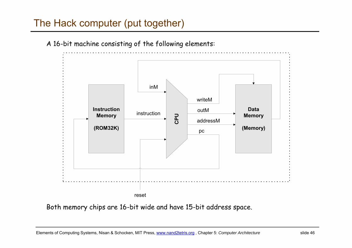
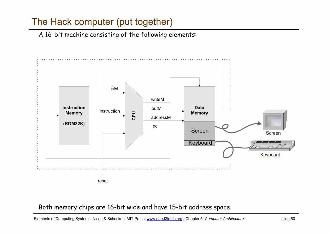
The Hack computer (put together)
A 16-bit machine consisting of the following elements:
Both memory chips are 16-bit wide and have 15-bit address space.
DataMemory
(Memory)
instruction
CPU
InstructionMemory
(ROM32K)
inM
outM
addressM
writeM
pc
reset
Elements of Computing Systems, Nisan & Schocken, MIT Press, www.nand2tetris.org , Chapter 5: Computer Architecture slide 47
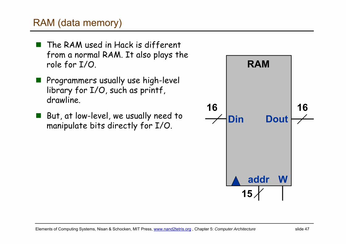
RAM (data memory)
The RAM used in Hack is different from a normal RAM. It also plays the role for I/O.
Programmers usually use high-level library for I/O, such as printf, drawline.
But, at low-level, we usually need to manipulate bits directly for I/O.
RAM
W
Din
addr
Dout16 16
15
Elements of Computing Systems, Nisan & Schocken, MIT Press, www.nand2tetris.org , Chapter 5: Computer Architecture slide 48
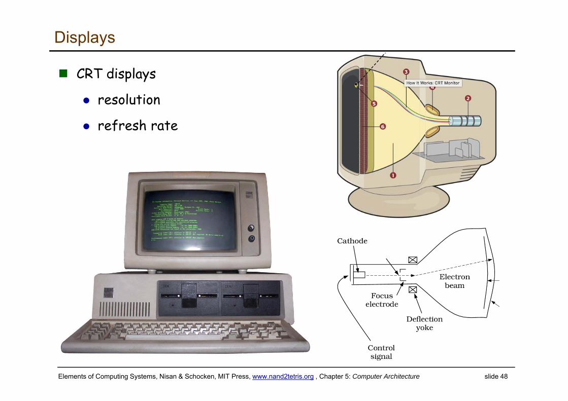
Displays
CRT displays
resolution
refresh rate
Elements of Computing Systems, Nisan & Schocken, MIT Press, www.nand2tetris.org , Chapter 5: Computer Architecture slide 49
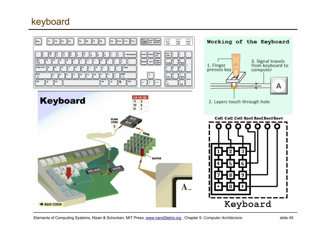
keyboard
Elements of Computing Systems, Nisan & Schocken, MIT Press, www.nand2tetris.org , Chapter 5: Computer Architecture slide 50
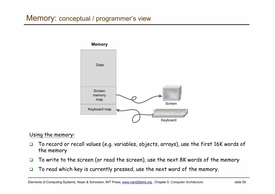
Memory: conceptual / programmer’s view
Using the memory:
To record or recall values (e.g. variables, objects, arrays), use the first 16K words of the memory
To write to the screen (or read the screen), use the next 8K words of the memory
To read which key is currently pressed, use the next word of the memory.
Data
Screen memory
map
Keyboard map
Memory
Keyboard
Screen
Elements of Computing Systems, Nisan & Schocken, MIT Press, www.nand2tetris.org , Chapter 5: Computer Architecture slide 51
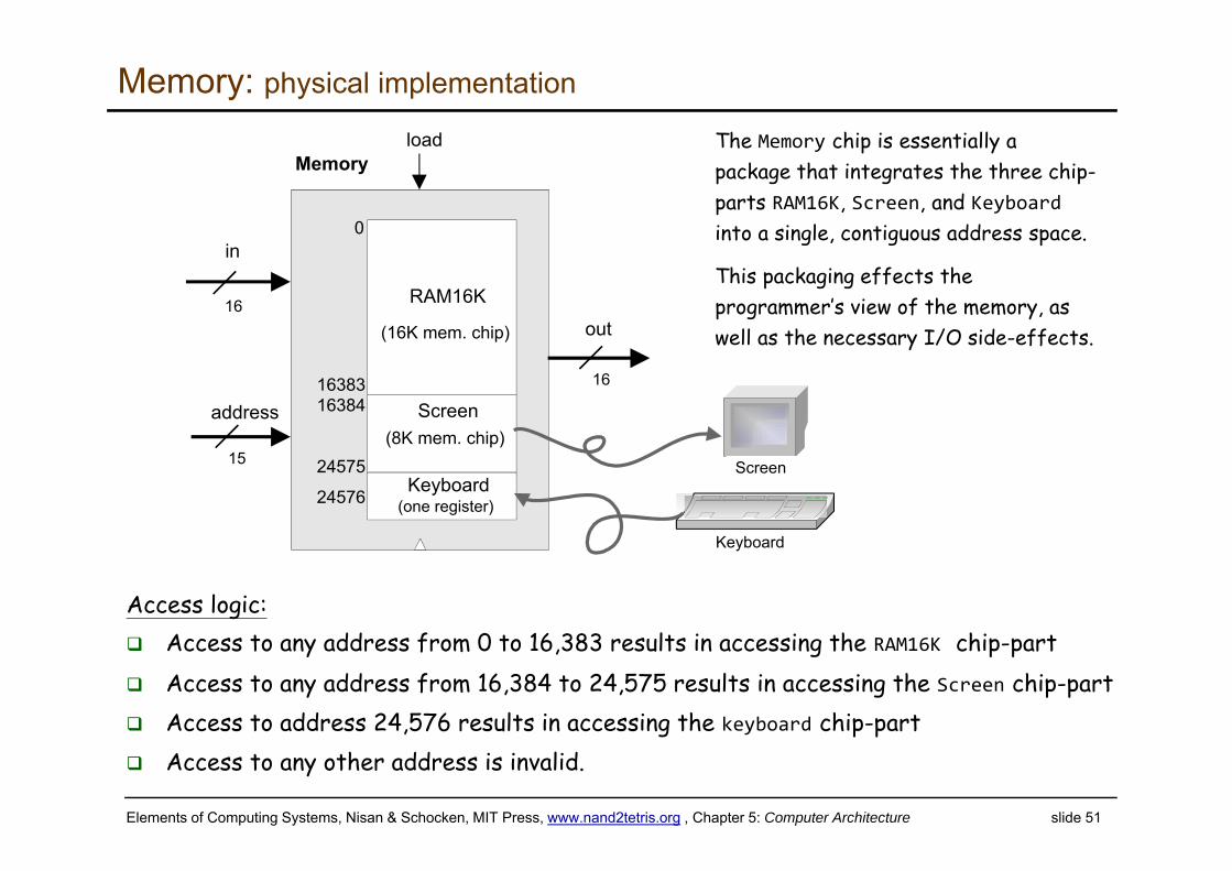
Memory: physical implementation
Access logic: Access to any address from 0 to 16,383 results in accessing the RAM16K chip-part Access to any address from 16,384 to 24,575 results in accessing the Screen chip-part Access to address 24,576 results in accessing the keyboard chip-part Access to any other address is invalid.
load
out
in
16
15
16
RAM16K
(16K mem. chip)
address
0
16383Screen
(8K mem. chip)
16384
24575
24576 Keyboard(one register)
Memory
Keyboard
Screen
The Memory chip is essentially a package that integrates the three chip-parts RAM16K, Screen, and Keyboardinto a single, contiguous address space.
This packaging effects the programmer’s view of the memory, as well as the necessary I/O side-effects.
Elements of Computing Systems, Nisan & Schocken, MIT Press, www.nand2tetris.org , Chapter 5: Computer Architecture slide 52
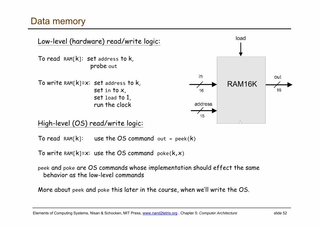
Data memory
Low-level (hardware) read/write logic:
To read RAM[k]: set address to k,probe out
To write RAM[k]=x: set address to k,set in to x, set load to 1, run the clock
High-level (OS) read/write logic:
To read RAM[k]: use the OS command out = peek(k)
To write RAM[k]=x: use the OS command poke(k,x)
peek and poke are OS commands whose implementation should effect the same behavior as the low-level commands
More about peek and poke this later in the course, when we’ll write the OS.
load
Elements of Computing Systems, Nisan & Schocken, MIT Press, www.nand2tetris.org , Chapter 5: Computer Architecture slide 53
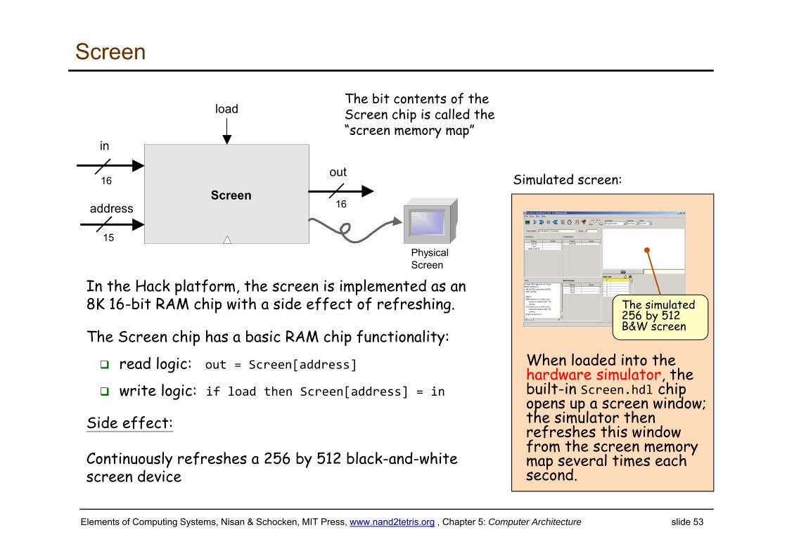
Screen
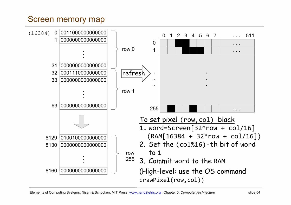
In the Hack platform, the screen is implemented as an 8K 16-bit RAM chip with a side effect of refreshing.
The Screen chip has a basic RAM chip functionality:
read logic: out = Screen[address]
write logic: if load then Screen[address] = in
Side effect:
Continuously refreshes a 256 by 512 black-and-white screen device
load
out
in
16
15
16addressScreen
PhysicalScreen
The bit contents of the Screen chip is called the “screen memory map”
The simulated 256 by 512 B&W screen
When loaded into the hardware simulator, the built-in Screen.hdl chip opens up a screen window; the simulator then refreshes this window from the screen memory map several times each second.
Simulated screen:
Elements of Computing Systems, Nisan & Schocken, MIT Press, www.nand2tetris.org , Chapter 5: Computer Architecture slide 54
01
255
.
.
.
. . .0 1 2 3 4 5 6 7 51100110000000000000000000000000000
0000000000000000
01
31
...row 0
00011100000000000000000000000000
0000000000000000
3233
63
...row 1
01001000000000000000000000000000
0000000000000000
81298130
8160
...row255
. . .
. . .
. . .
.
.
.
refresh several timeseach second
(16384)
To set pixel (row,col) black1. word=Screen[32*row + col/16](RAM[16384 + 32*row + col/16])
2. Set the (col%16)‐th bit of wordto 1
3. Commit word to the RAM(High-level: use the OS commanddrawPixel(row,col))
Screen memory map
refresh
Elements of Computing Systems, Nisan & Schocken, MIT Press, www.nand2tetris.org , Chapter 5: Computer Architecture slide 55
keyboard
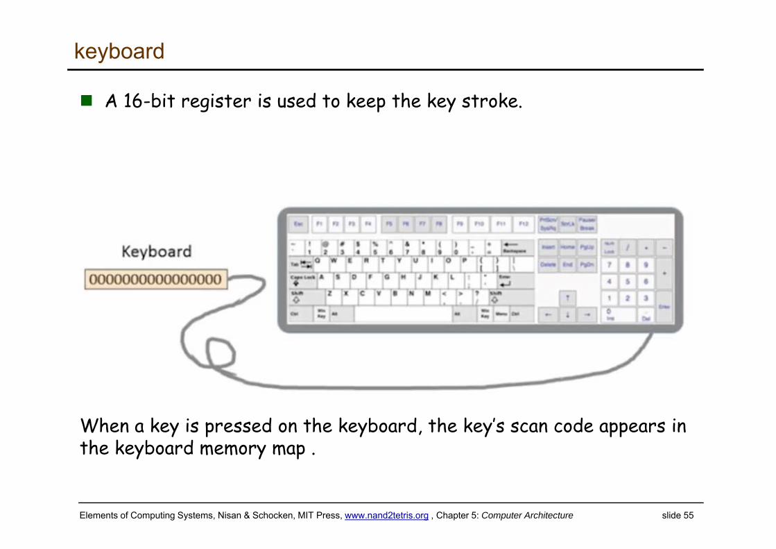
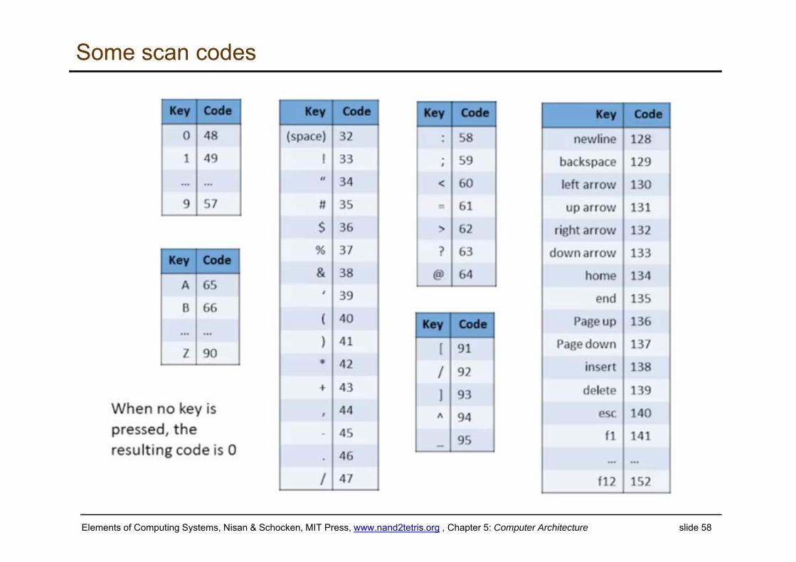
A 16-bit register is used to keep the key stroke.
When a key is pressed on the keyboard, the key’s scan code appears in the keyboard memory map .
Elements of Computing Systems, Nisan & Schocken, MIT Press, www.nand2tetris.org , Chapter 5: Computer Architecture slide 56
keyboard
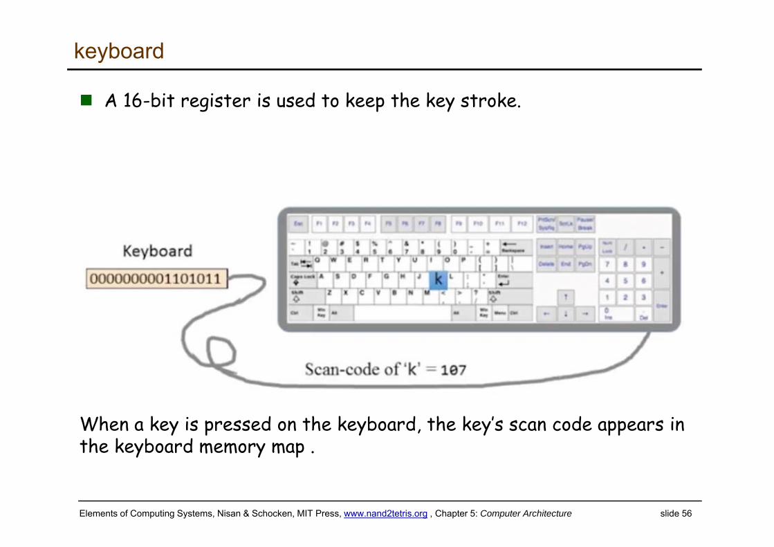
A 16-bit register is used to keep the key stroke.
When a key is pressed on the keyboard, the key’s scan code appears in the keyboard memory map .
Elements of Computing Systems, Nisan & Schocken, MIT Press, www.nand2tetris.org , Chapter 5: Computer Architecture slide 57
Keyboard
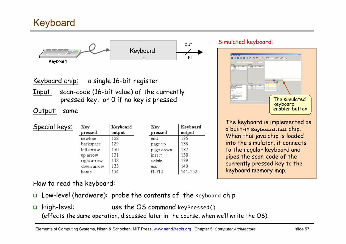
Keyboard chip: a single 16-bit registerInput: scan-code (16-bit value) of the currently
pressed key, or 0 if no key is pressedOutput: same
How to read the keyboard:
Low-level (hardware): probe the contents of the Keyboard chip
High-level: use the OS command keyPressed() (effects the same operation, discussed later in the course, when we’ll write the OS).
Special keys:The keyboard is implemented as a built-in Keyboard.hdl chip. When this java chip is loaded into the simulator, it connects to the regular keyboard and pipes the scan-code of the currently pressed key to the keyboard memory map.
The simulated keyboard enabler button
Simulated keyboard:
Elements of Computing Systems, Nisan & Schocken, MIT Press, www.nand2tetris.org , Chapter 5: Computer Architecture slide 58
Some scan codes
Elements of Computing Systems, Nisan & Schocken, MIT Press, www.nand2tetris.org , Chapter 5: Computer Architecture slide 59
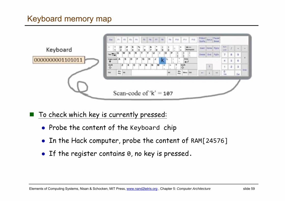
Keyboard memory map
To check which key is currently pressed:
Probe the content of the Keyboard chip
In the Hack computer, probe the content of RAM[24576]
If the register contains 0, no key is pressed.
Elements of Computing Systems, Nisan & Schocken, MIT Press, www.nand2tetris.org , Chapter 5: Computer Architecture slide 60
A 16-bit machine consisting of the following elements:
Both memory chips are 16-bit wide and have 15-bit address space.
DataMemory
(Memory)
instruction
CPU
InstructionMemory
(ROM32K)
inM
outM
addressM
writeM
pc
reset
The Hack computer (put together)
Screen
Keyboard
Elements of Computing Systems, Nisan & Schocken, MIT Press, www.nand2tetris.org , Chapter 5: Computer Architecture slide 61
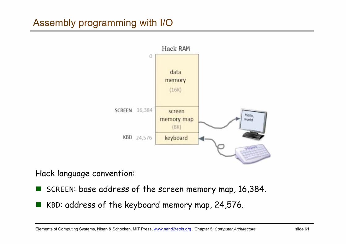
Assembly programming with I/O
Hack language convention:
SCREEN: base address of the screen memory map, 16,384.
KBD: address of the keyboard memory map, 24,576.
Elements of Computing Systems, Nisan & Schocken, MIT Press, www.nand2tetris.org , Chapter 5: Computer Architecture slide 62
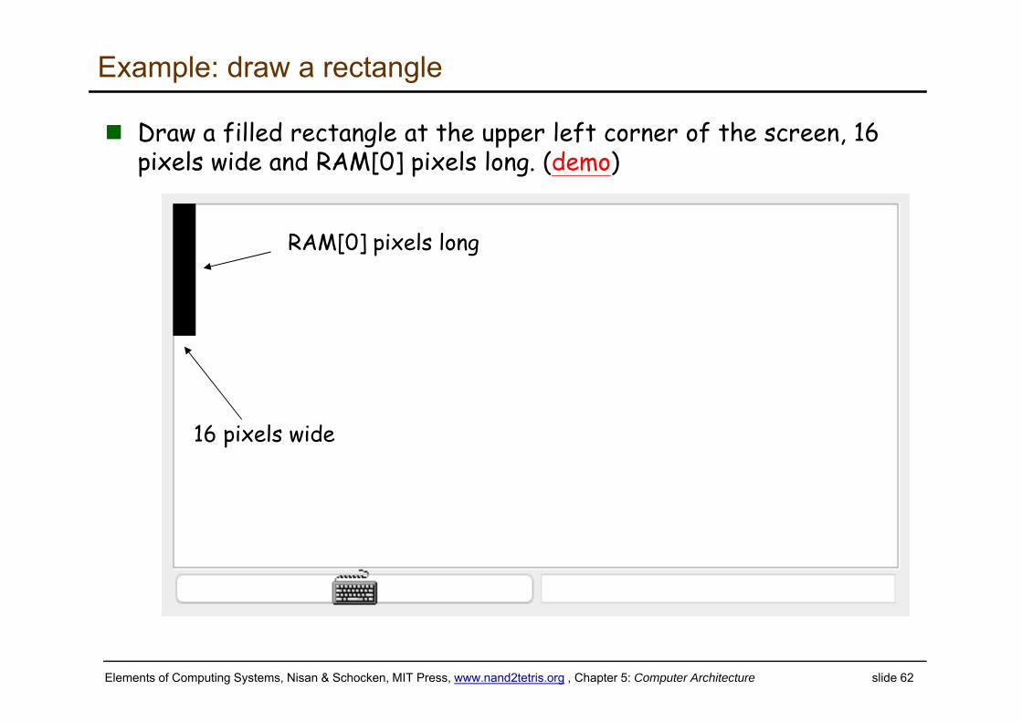
Example: draw a rectangle
Draw a filled rectangle at the upper left corner of the screen, 16 pixels wide and RAM[0] pixels long. (demo)
16 pixels wide
RAM[0] pixels long
Elements of Computing Systems, Nisan & Schocken, MIT Press, www.nand2tetris.org , Chapter 5: Computer Architecture slide 63
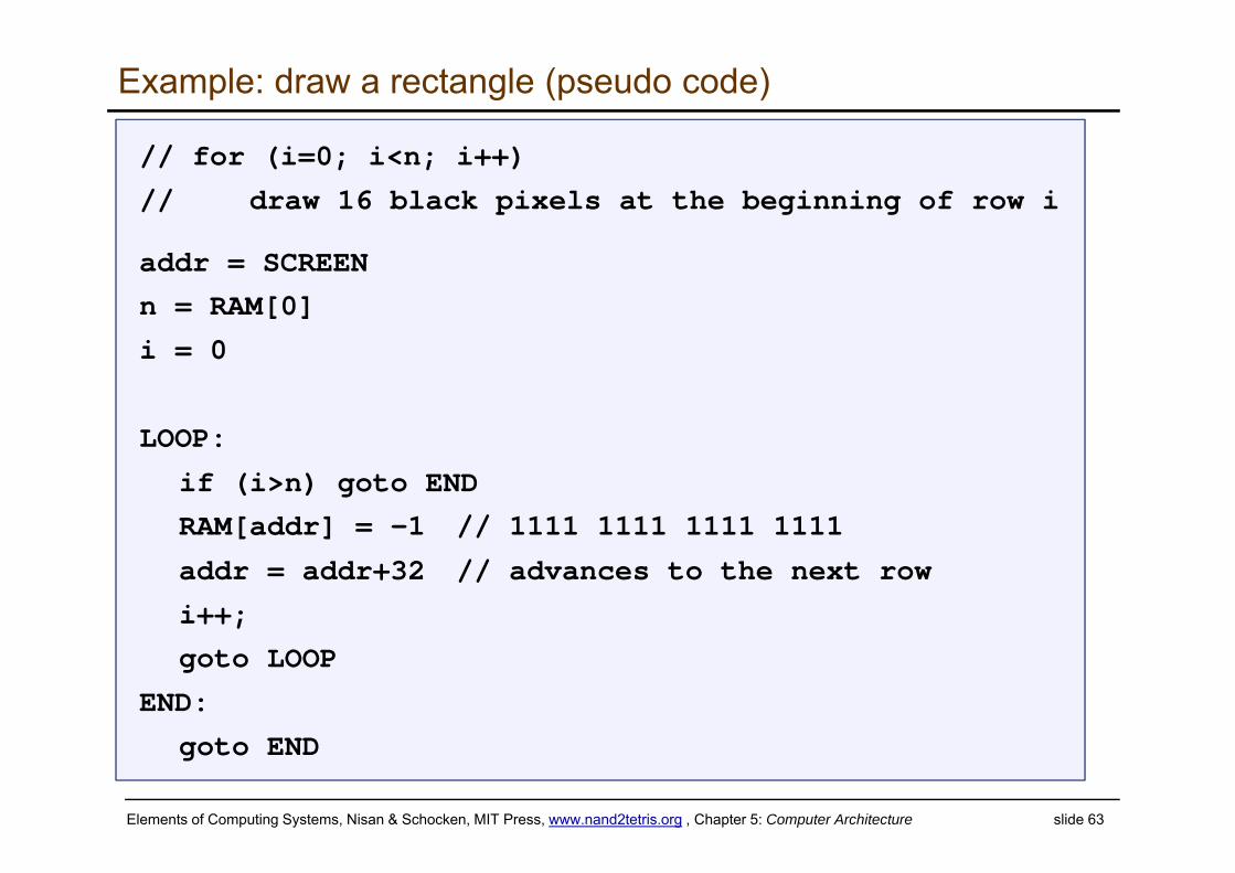
Example: draw a rectangle (pseudo code)
// for (i=0; i<n; i++)
// draw 16 black pixels at the beginning of row i
addr = SCREEN
n = RAM[0]
i = 0
LOOP:
if (i>n) goto END
RAM[addr] = -1 // 1111 1111 1111 1111
addr = addr+32 // advances to the next row
i++;
goto LOOP
END:
goto END
Elements of Computing Systems, Nisan & Schocken, MIT Press, www.nand2tetris.org , Chapter 5: Computer Architecture slide 64
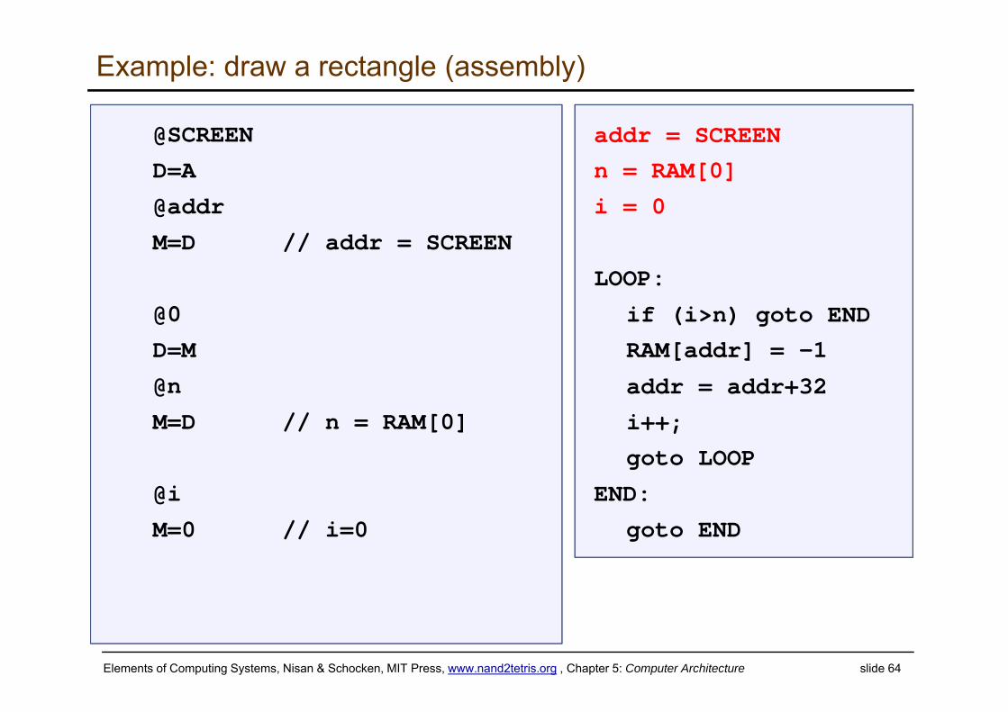
Example: draw a rectangle (assembly)
addr = SCREEN
n = RAM[0]
i = 0
LOOP:
if (i>n) goto END
RAM[addr] = -1
addr = addr+32
i++;
goto LOOP
END:
goto END
@SCREEN
D=A
@addr
M=D // addr = SCREEN
@0
D=M
@n
M=D // n = RAM[0]
@i
M=0 // i=0
Elements of Computing Systems, Nisan & Schocken, MIT Press, www.nand2tetris.org , Chapter 5: Computer Architecture slide 65
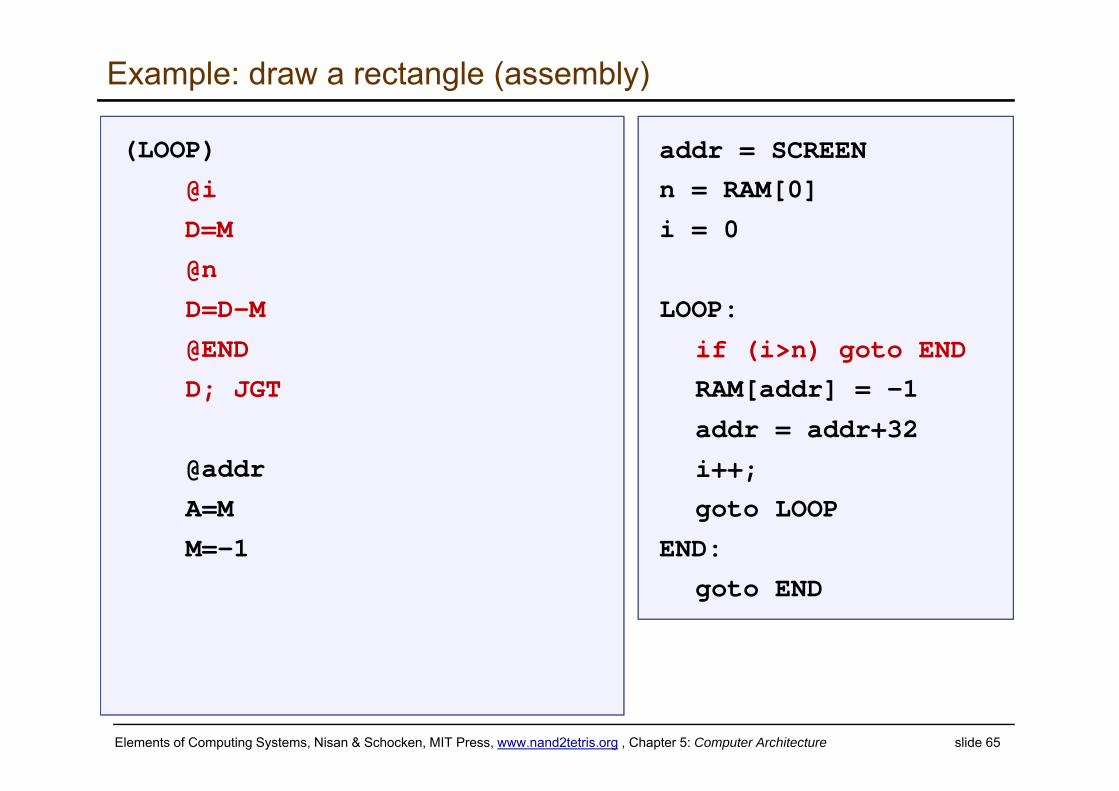
Example: draw a rectangle (assembly)
addr = SCREEN
n = RAM[0]
i = 0
LOOP:
if (i>n) goto END
RAM[addr] = -1
addr = addr+32
i++;
goto LOOP
END:
goto END
(LOOP)
@i
D=M
@n
D=D-M
@END
D; JGT
@addr
A=M
M=-1
Elements of Computing Systems, Nisan & Schocken, MIT Press, www.nand2tetris.org , Chapter 5: Computer Architecture slide 66
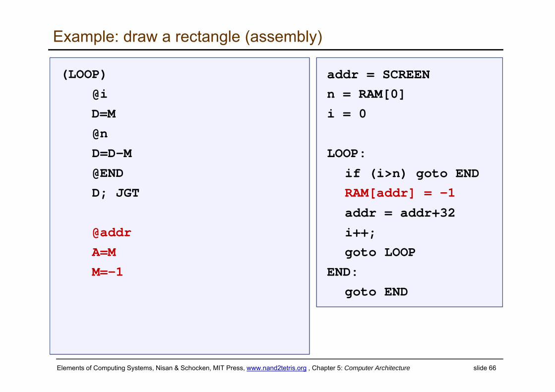
Example: draw a rectangle (assembly)
addr = SCREEN
n = RAM[0]
i = 0
LOOP:
if (i>n) goto END
RAM[addr] = -1
addr = addr+32
i++;
goto LOOP
END:
goto END
(LOOP)
@i
D=M
@n
D=D-M
@END
D; JGT
@addr
A=M
M=-1
Elements of Computing Systems, Nisan & Schocken, MIT Press, www.nand2tetris.org , Chapter 5: Computer Architecture slide 67
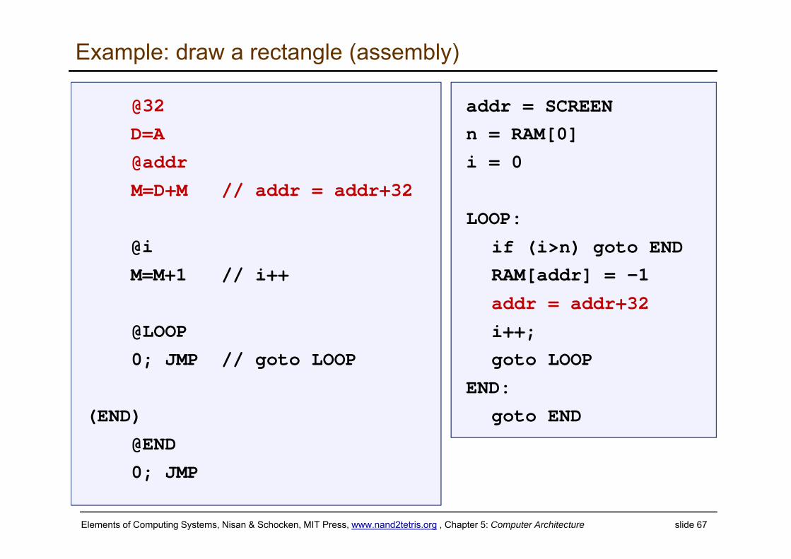
Example: draw a rectangle (assembly)
addr = SCREEN
n = RAM[0]
i = 0
LOOP:
if (i>n) goto END
RAM[addr] = -1
addr = addr+32
i++;
goto LOOP
END:
goto END
@32
D=A
@addr
M=D+M // addr = addr+32
@i
M=M+1 // i++
@LOOP
0; JMP // goto LOOP
(END)
@END
0; JMP
Elements of Computing Systems, Nisan & Schocken, MIT Press, www.nand2tetris.org , Chapter 5: Computer Architecture slide 68
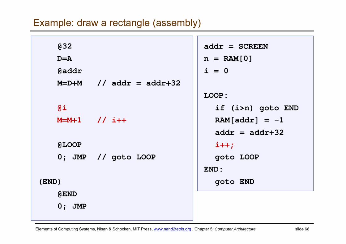
Example: draw a rectangle (assembly)
addr = SCREEN
n = RAM[0]
i = 0
LOOP:
if (i>n) goto END
RAM[addr] = -1
addr = addr+32
i++;
goto LOOP
END:
goto END
@32
D=A
@addr
M=D+M // addr = addr+32
@i
M=M+1 // i++
@LOOP
0; JMP // goto LOOP
(END)
@END
0; JMP
Elements of Computing Systems, Nisan & Schocken, MIT Press, www.nand2tetris.org , Chapter 5: Computer Architecture slide 69
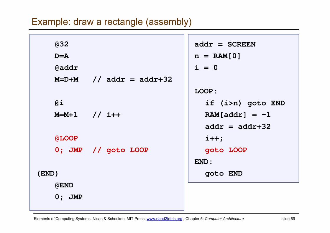
Example: draw a rectangle (assembly)
addr = SCREEN
n = RAM[0]
i = 0
LOOP:
if (i>n) goto END
RAM[addr] = -1
addr = addr+32
i++;
goto LOOP
END:
goto END
@32
D=A
@addr
M=D+M // addr = addr+32
@i
M=M+1 // i++
@LOOP
0; JMP // goto LOOP
(END)
@END
0; JMP
Elements of Computing Systems, Nisan & Schocken, MIT Press, www.nand2tetris.org , Chapter 5: Computer Architecture slide 70
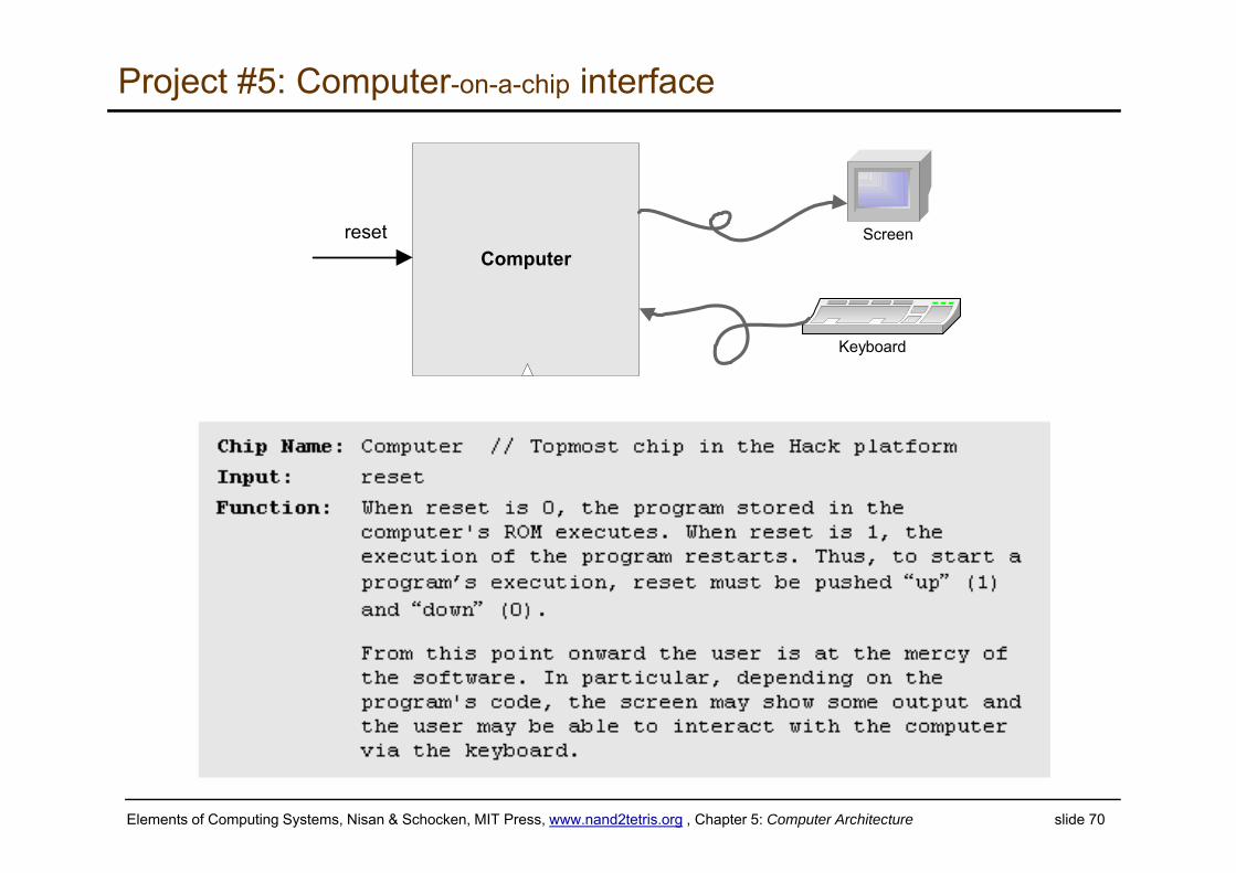
Project #5: Computer-on-a-chip interface
Computerreset
Keyboard
Screen
Elements of Computing Systems, Nisan & Schocken, MIT Press, www.nand2tetris.org , Chapter 5: Computer Architecture slide 71
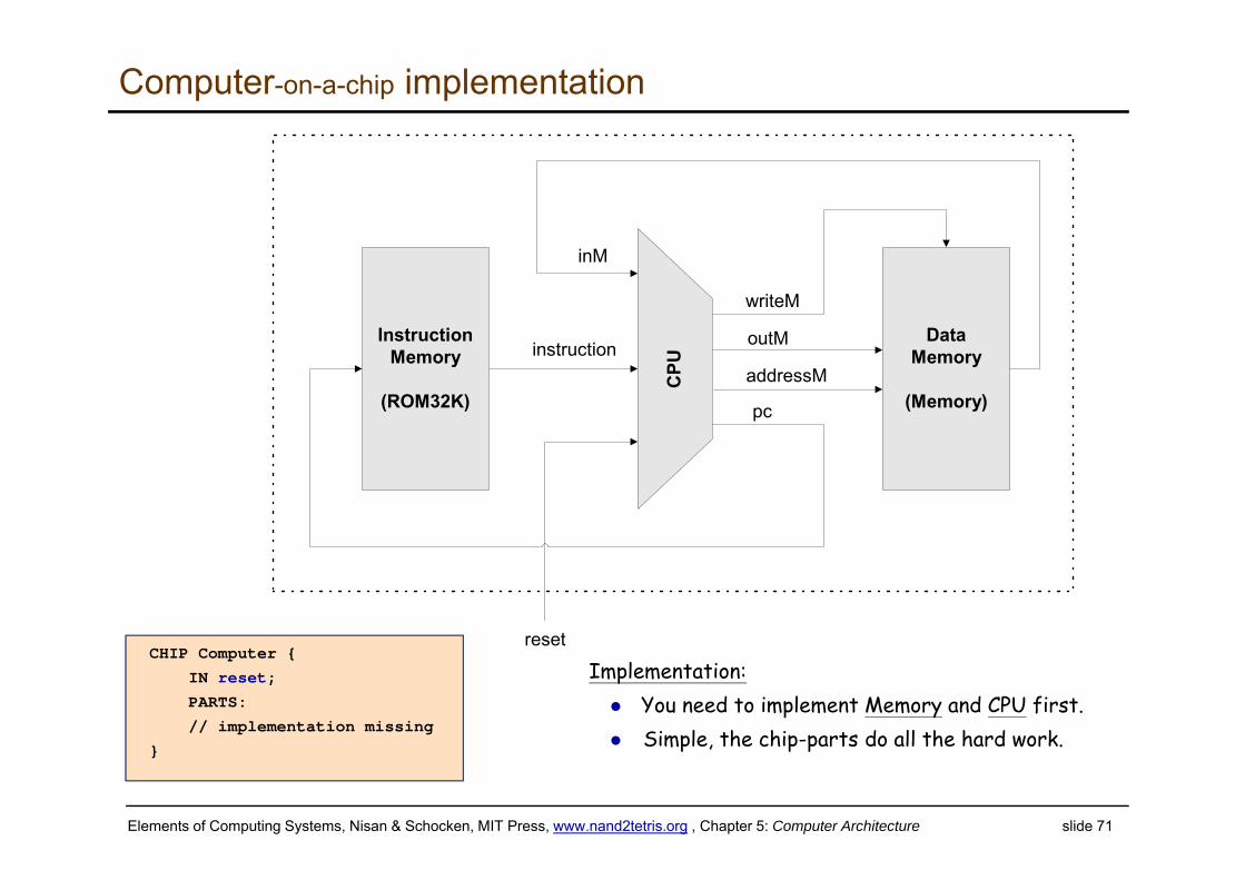
Computer-on-a-chip implementation
DataMemory
(Memory)
instruction
CPU
InstructionMemory
(ROM32K)
inM
outM
addressM
writeM
pc
resetCHIP Computer {
IN reset;
PARTS:
// implementation missing
}
Implementation: You need to implement Memory and CPU first. Simple, the chip-parts do all the hard work.
Elements of Computing Systems, Nisan & Schocken, MIT Press, www.nand2tetris.org , Chapter 5: Computer Architecture slide 72
Perspective: from here to a “real” computer
Caching
More I/O units
Special-purpose processors (I/O, graphics, communications, …)
Multi-core / parallelism
Efficiency
Energy consumption considerations
And more ...