Easy-to-Swallow Antenna and Propagation - Electrical and … · · 2014-04-18design of wireless...
9
74 June 2013 1527-3342/13/$31.00©2013IEEE Digital Object Identifier 10.1109/MMM.2013.2248587 Mehmet R. Yuce (mehmet.yuce@ monash.edu) is with the Electrical and Computer Systems Engineering Department, Monash University, Clayton, VIC 3800, Australia. Tharaka Dissanayake is with the School of Electrical Engineering and Computer Science, The University of Newcastle, University Drive, NSW 2308, Australia. Date of publication: 7 May 2013 FOCUSED ISSUE FEATURE T he first part of this series [1] reviewed recent developments in the design of wireless telemetry units for electronic pill technology and discussed the challenges and developments for successful implementation of high-resolution video-based electronic pills. This second part reviews potential miniature antenna mod- ules that fit inside the electronic pills and discusses propagation analysis of RF signals through the dense in-body environment. Antenna Design and Propagation It is commonly known that propagation through the body has higher loss at higher frequencies, with the characteristics varying depending on location of the antenna (i.e., on-body ver- sus implanted/injected). Yu et al. have shown that for ingested antennas, it is important to optimize the through- body propagation characteristics together with the antenna to obtain optimum antenna radiation at the design frequency [2]. Anten- nas can be placed inside or on the body. A comprehensive review of on-body antenna design for body area networks (BANs) is given in [3]. For on-body antennas, the sepa- ration distance between the antenna and the body affects an antenna’s per- formance [4]. The performance degrades as the antenna is placed close to the body due Mehmet R. Yuce and Tharaka Dissanayake © ISWOOP & DIGITAL STOCK Easy-to-Swallow Antenna and Propagation
-
Upload
nguyenmien -
Category
Documents
-
view
219 -
download
3
Transcript of Easy-to-Swallow Antenna and Propagation - Electrical and … · · 2014-04-18design of wireless...
74 June 20131527-3342/13/$31.00©2013IEEE
Digital Object Identifier 10.1109/MMM.2013.2248587
Mehmet R. Yuce (mehmet.yuce@ monash.edu) is with the Electrical and Computer Systems Engineering Department, Monash University, Clayton, VIC 3800, Australia. Tharaka Dissanayake is with the School of Electrical Engineering and Computer Science,
The University of Newcastle, University Drive, NSW 2308, Australia.
Date of publication: 7 May 2013
FOCU
SED
ISSU
E FE
ATUR
E
The first part of this series [1] reviewed recent developments in the design of wireless telemetry units for electronic pill technology and discussed the challenges and developments for successful implementation of high-resolution video-based electronic pills. This second part reviews potential miniature antenna mod-
ules that fit inside the electronic pills and discusses propagation analysis of RF signals through the dense in-body environment.
Antenna Design and PropagationIt is commonly known that propagation through the body has higher loss at higher frequencies, with the characteristics varying depending on location of the antenna (i.e., on-body ver-sus implanted/injected). Yu et al. have shown that for ingested antennas, it is important to optimize the through-body propagation characteristics together with the antenna to obtain optimum antenna radiation at the design frequency [2]. Anten-nas can be placed inside or on the body. A comprehensive review of on-body antenna design for body area networks (BANs) is given in [3]. For on-body antennas, the sepa-ration distance between the antenna and the body affects an antenna’s per-formance [4]. The performance degrades as the antenna is placed close to the body due
Mehmet R. Yuce and Tharaka Dissanayake
© iswoop & digital stock
Easy-to-Swallow Antenna and Propagation
June 2013 75
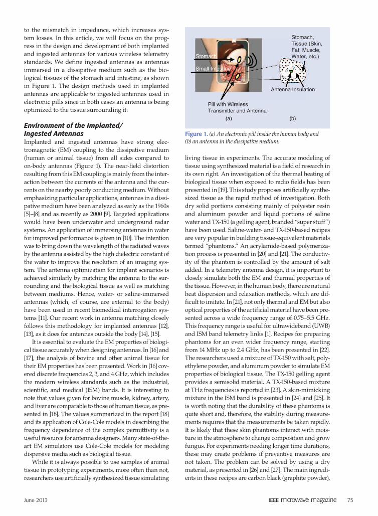
to the mismatch in impedance, which increases sys-tem losses. In this article, we will focus on the prog-ress in the design and development of both implanted and ingested antennas for various wireless telemetry standards. We define ingested antennas as antennas immersed in a dissipative medium such as the bio-logical tissues of the stomach and intestine, as shown in Figure 1. The design methods used in implanted antennas are applicable to ingested antennas used in electronic pills since in both cases an antenna is being optimized to the tissue surrounding it.
Environment of the Implanted/ Ingested AntennasImplanted and ingested antennas have strong elec-tromagnetic (EM) coupling to the dissipative medium (human or animal tissue) from all sides compared to on-body antennas (Figure 1). The near-field distortion resulting from this EM coupling is mainly from the inter-action between the currents of the antenna and the cur-rents on the nearby poorly conducting medium. Without emphasizing particular applications, antennas in a dissi-pative medium have been analyzed as early as the 1960s [5]–[8] and as recently as 2000 [9]. Targeted applications would have been underwater and underground radar systems. An application of immersing antennas in water for improved performance is given in [10]. The intention was to bring down the wavelength of the radiated waves by the antenna assisted by the high dielectric constant of the water to improve the resolution of an imaging sys-tem. The antenna optimization for implant scenarios is achieved similarly by matching the antenna to the sur-rounding and the biological tissue as well as matching between mediums. Hence, water- or saline-immersed antennas (which, of course, are external to the body) have been used in recent biomedical interrogation sys-tems [11]. Our recent work in antenna matching closely follows this methodology for implanted antennas [12], [13], as it does for antennas outside the body [14], [15].
It is essential to evaluate the EM properties of biologi-cal tissue accurately when designing antennas. In [16] and [17], the analysis of bovine and other animal tissue for their EM properties has been presented. Work in [16] cov-ered discrete frequencies 2, 3, and 4 GHz, which includes the modern wireless standards such as the industrial, scientific, and medical (ISM) bands. It is interesting to note that values given for bovine muscle, kidney, artery, and liver are comparable to those of human tissue, as pre-sented in [18]. The values summarized in the report [18] and its application of Cole-Cole models in describing the frequency dependence of the complex permittivity is a useful resource for antenna designers. Many state-of-the-art EM simulators use Cole-Cole models for modeling dispersive media such as biological tissue.
While it is always possible to use samples of animal tissue in prototyping experiments, more often than not, researchers use artificially synthesized tissue simulating
living tissue in experiments. The accurate modeling of tissue using synthesized material is a field of research in its own right. An investigation of the thermal heating of biological tissue when exposed to radio fields has been presented in [19]. This study proposes artificially synthe-sized tissue as the rapid method of investigation. Both dry solid portions consisting mainly of polyester resin and aluminum powder and liquid portions of saline water and TX-150 (a gelling agent, branded “super stuff”) have been used. Saline-water- and TX-150-based recipes are very popular in building tissue-equivalent materials termed “phantoms.” An acrylamide-based polymeriza-tion process is presented in [20] and [21]. The conductiv-ity of the phantom is controlled by the amount of salt added. In a telemetry antenna design, it is important to closely simulate both the EM and thermal properties of the tissue. However, in the human body, there are natural heat dispersion and relaxation methods, which are dif-ficult to imitate. In [21], not only thermal and EM but also optical properties of the artificial material have been pre-sented across a wide frequency range of 0.75–5.5 GHz. This frequency range is useful for ultrawideband (UWB) and ISM band telemetry links [1]. Recipes for preparing phantoms for an even wider frequency range, starting from 14 MHz up to 2.4 GHz, has been presented in [22]. The researchers used a mixture of TX-150 with salt, poly-ethylene powder, and aluminum powder to simulate EM properties of biological tissue. The TX-150 gelling agent provides a semisolid material. A TX-150-based mixture at THz frequencies is reported in [23]. A skin-mimicking mixture in the ISM band is presented in [24] and [25]. It is worth noting that the durability of these phantoms is quite short and, therefore, the stability during measure-ments requires that the measurements be taken rapidly. It is likely that these skin phantoms interact with mois-ture in the atmosphere to change composition and grow fungus. For experiments needing longer time durations, these may create problems if preventive measures are not taken. The problem can be solved by using a dry material, as presented in [26] and [27]. The main ingredi-ents in these recipes are carbon black (graphite powder),
stomach
stomach,tissue (skin,Fat, Muscle,water, etc.)
antenna insulation
small intestine
pill with wirelesstransmitter and antenna
(a) (b)
Figure 1. (a) An electronic pill inside the human body and (b) an antenna in the dissipative medium.
76 June 2013
ceramic powder and a bonding resin. The polymer pow-der (polyethylene methacrylate, in [27]), carbon powder, and binding agent composition is varied to control the EM properties of the solid phantom material. In this case, the role of salt is played by the graphite powder, and water is replaced by a liquid monomer. The reported plastics have lasted close to a year without much change to its properties, according to [27].
In-Body PropagationAntenna design and frequency selection for an electronic pill application should consider the in-body propagation of radio waves. Tissue properties change with frequency and become extremely lossy at higher frequencies. There have been many studies of the EM interaction with the human body for externally originated transverse EM (TEM) waves [28], [29]. The focus of the numerical [11] and analytical techniques was to calculate specific absorption ratio (SAR) of the human body from external EM sources, such as mobile phones for safety [3], [30], [31]. In addition, imaging and hyperthermia treatment [20] requires this information. Any development of a channel model for implanted and ingested communica-tion must consider the existence of losses in conductive biological tissue.
There have been fewer studies of EM interactions with signals originating from within the body. A chan-nel model for in-body propagation has been presented in [32], using an implanted dipole and its near-field and far-field absorption. Although a homogeneous body model has been considered, it is worth noting that the absorption mechanisms in the two zones are different. In addition, the situation is more complicated when a heterogeneous body model is used. Note that in [32], both the transmit and receive antennas are implanted. In contrast, many telemetry systems will have at least one
antenna outside. Analytical expressions for propagation from in-body to air has been given in [33] together with numerical simulations of the same. The studies reported in [34] and [35] have used more complex numerical simulations. Those simulations have considered hetero-geneous body models, compiled by the Visible Human Project [36] in a numerical software package. The gen-erated human model is divided into cubic voxels with a 5 mm edge length. This cell size is selected for the computer resources available to the authors to run the EM simulation using the finite-different time domain (FDTD) method, a computational modeling technique that uses grid-based differential time-domain numeri-cal methods. For EM simulations in biomedical applica-tions, the human body mesh is divided into cells (also referred as cubic voxels) to define and compute EM and electric field components. The antenna in [34] has always matched despite the loading of the surrounding tissue inside the gastrointestinal (GI) system for different ori-entations and frequencies, which makes it a good propa-gation-focused study. Several important conclusions for antenna design, such as the maximum near-field radia-tion, occurs between 450–900 MHz, with vertical polar-ization suffering more attenuation inside the gut, have been presented. At high frequencies, numerical simula-tions of this nature require a substantial amount of com-puting resources. A recent analysis done at frequencies 402 MHz, 868 MHz, and 2.4 GHz has delivered results in both simulations and experiments [37]. The frequen-cies studied are commonly used medical and ISM fre-quencies (See [1, Table II]). A simple path loss model has also been presented. For broadband implanted antenna applications, propagation models at higher frequencies are needed. Extra care must be taken to investigate near-field SAR at higher frequencies, as there is increased conductivity of biological tissue and, therefore, a need
for higher power at the implanted or ingested transmitters.
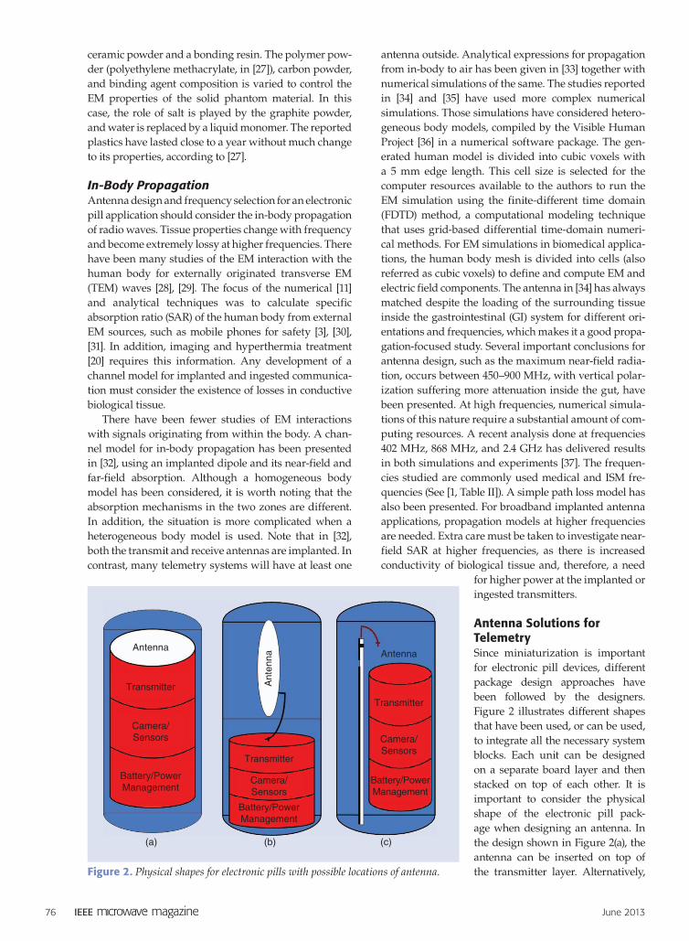
Antenna Solutions for TelemetrySince miniaturization is important for electronic pill devices, different package design approaches have been followed by the designers. Figure 2 illustrates different shapes that have been used, or can be used, to integrate all the necessary system blocks. Each unit can be designed on a separate board layer and then stacked on top of each other. It is important to consider the physical shape of the electronic pill pack-age when designing an antenna. In the design shown in Figure 2(a), the antenna can be inserted on top of the transmitter layer. Alternatively,
(a)
antennaantenna
ant
enna
transmitter
transmitter
transmitter
camera/sensors
camera/sensors
camera/sensors
Battery/powerManagement
Battery/powerManagement
Battery/powerManagement
(b) (c)
Figure 2. Physical shapes for electronic pills with possible locations of antenna.
June 2013 77
the capsule shape can also be divided into two regions where the antenna can be placed in the upper half, whereas the remaining electronic units are packed in the lower half. Plac-ing the antenna at one side of the electronic units is another possibility [Figure 2(c)]. It is important to note that commer-cially available minicameras can easily be integrated into electronic pills [38]. Miniature rechargeable battery technolo-gies are also being developed [39] with dimensions around 5 mm that can easily be inte-grated in a capsule structure, as shown in Figure 2.
Theoretically, the smallest implanted antenna is the Hertzian dipole [9]. However, this dipole is not particu-larly useful for fully realizable systems. Nevertheless, dipoles are indispensable as a reference element for the-oretical analysis. There are a few widely used antenna designs that are specifically for implanted and ingested applications, as we shall discuss in this section.
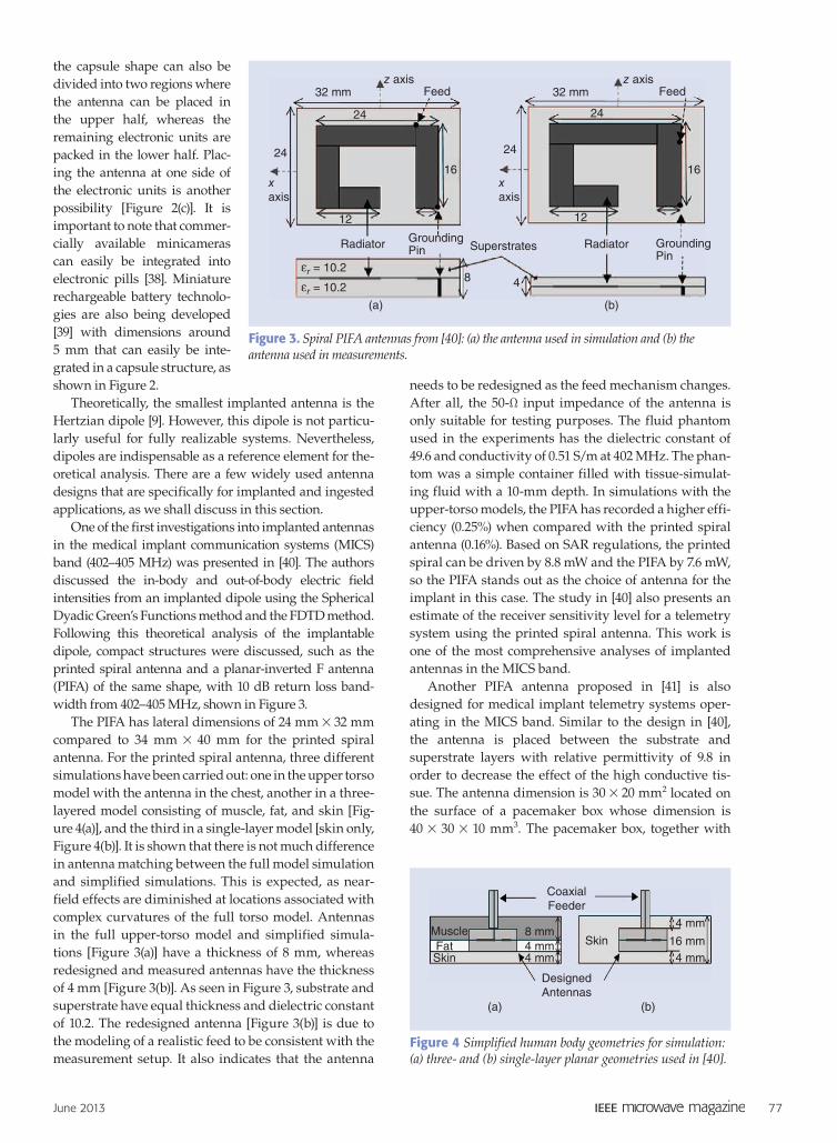
One of the first investigations into implanted antennas in the medical implant communication systems (MICS) band (402–405 MHz) was presented in [40]. The authors discussed the in-body and out-of-body electric field intensities from an implanted dipole using the Spherical Dyadic Green’s Functions method and the FDTD method. Following this theoretical analysis of the implantable dipole, compact structures were discussed, such as the printed spiral antenna and a planar-inverted F antenna (PIFA) of the same shape, with 10 dB return loss band-width from 402–405 MHz, shown in Figure 3.
The PIFA has lateral dimensions of 24 mm # 32 mm compared to 34 mm # 40 mm for the printed spiral antenna. For the printed spiral antenna, three different simulations have been carried out: one in the upper torso model with the antenna in the chest, another in a three-layered model consisting of muscle, fat, and skin [Fig-ure 4(a)], and the third in a single-layer model [skin only, Figure 4(b)]. It is shown that there is not much difference in antenna matching between the full model simulation and simplified simulations. This is expected, as near-field effects are diminished at locations associated with complex curvatures of the full torso model. Antennas in the full upper-torso model and simplified simula-tions [Figure 3(a)] have a thickness of 8 mm, whereas redesigned and measured antennas have the thickness of 4 mm [Figure 3(b)]. As seen in Figure 3, substrate and superstrate have equal thickness and dielectric constant of 10.2. The redesigned antenna [Figure 3(b)] is due to the modeling of a realistic feed to be consistent with the measurement setup. It also indicates that the antenna
needs to be redesigned as the feed mechanism changes. After all, the 50-Ω input impedance of the antenna is only suitable for testing purposes. The fluid phantom used in the experiments has the dielectric constant of 49.6 and conductivity of 0.51 S/m at 402 MHz. The phan-tom was a simple container filled with tissue-simulat-ing fluid with a 10-mm depth. In simulations with the upper-torso models, the PIFA has recorded a higher effi-ciency (0.25%) when compared with the printed spiral antenna (0.16%). Based on SAR regulations, the printed spiral can be driven by 8.8 mW and the PIFA by 7.6 mW, so the PIFA stands out as the choice of antenna for the implant in this case. The study in [40] also presents an estimate of the receiver sensitivity level for a telemetry system using the printed spiral antenna. This work is one of the most comprehensive analyses of implanted antennas in the MICS band.
Another PIFA antenna proposed in [41] is also designed for medical implant telemetry systems oper-ating in the MICS band. Similar to the design in [40], the antenna is placed between the substrate and superstrate layers with relative permittivity of 9.8 in order to decrease the effect of the high conductive tis-sue. The antenna dimension is 30 # 20 mm2 located on the surface of a pacemaker box whose dimension is 40 # 30 # 10 mm3. The pacemaker box, together with
z axis
xaxis
xaxis
z axis32 mm
Radiator
(a) (b)
superstratesgroundingpin
groundingpin
Radiator
24
2416
12 12
16
24
8 4fr = 10.2
fr = 10.2
24
Feed 32 mm Feed
Figure 3. Spiral PIFA antennas from [40]: (a) the antenna used in simulation and (b) the antenna used in measurements.
coaxialFeeder
designedantennas
MuscleFatskin
skin8 mm4 mm 16 mm4 mm
4 mm
4 mm
(a) (b)
Figure 4 Simplified human body geometries for simulation: (a) three- and (b) single-layer planar geometries used in [40].
78 June 2013
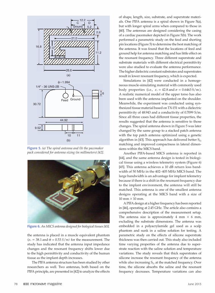
the antenna is placed in a muscle equivalent phantom ( . and 0.53 /S m)38 1r v =f = for the measurement. The study has indicated that the antenna input impedance changes and the resonant frequency shifts lower due to the high permittivity and conductivity of the human tissue as the implant depth increases.
The PIFA antenna structure has been studied by other researchers as well. Two antennas, both based on the PIFA principle, are presented in [42] to analyze the effects
of shape, length, size, substrate, and superstrate materi-als. One PIFA antenna is a spiral shown in Figure 5(a), but with longer spiral arms when compared to those in [40]. The antennas are designed considering the casing of a cardiac pacemaker depicted in Figure 5(b). The work performed a parametric study on the feed and shorting pin locations (Figure 5) to determine the best matching of the antenna. It was found that the locations of feed and ground help for antenna matching and has little effect on the resonant frequency. Three different superstrate and substrate materials with different electrical permittivity were also studied to evaluate the antenna performance. The higher dielectric constant substrates and superstrates result in lower resonant frequency, which is expected.
Simulations in [42] were conducted in a homoge-neous muscle-simulating material with commonly used body properties (i.e., . and 0.6463 S/m42 8rf v= = ). A realistic numerical model of the upper torso has also been used with the antenna implanted on the shoulder. Meanwhile, the experiment was conducted using syn-thesized tissue material based on TX-151 with a dielectric permittivity of 48.943 and a conductivity of 0.7099 S/m. Since all three cases had different tissue properties, the results suggested that the antenna is sensitive to those changes. The spiral antenna shown in Figure 5 was later changed by the same group to a stacked patch antenna with the top patch antenna optimized using a genetic algorithm in [43]. This approach has delivered better S11 matching and improved compactness in lateral dimen-sions within the MICS band.
Another PIFA-based MICS antenna is reported in [44], and the same antenna design is tested in biologi-cal tissue using a wireless telemetry system (Figure 6) [45]. This antenna achieves a 10 dB return loss band-width of 50 MHz in the 402–405 MHz MICS band. The large bandwidth is an advantage for implant telemetry because if there is a shift in the resonant frequency due to the implant environment, the antenna will still be matched. This antenna is one of the smallest antenna designs operating at the MICS band with a size of 10 mm # 10 mm.
A PIFA design at a higher frequency has been reported in [46], operating at 2.45 GHz. The article also contains a comprehensive description of the measurement setup. The antenna size is approximately 4 mm # 6 mm, excluding the substrate dimensions. The antenna was embedded in a polyacrylamide gel used as a scalp phantom and sunk in a saline solution for testing. A parametric study on the effects of silicone superstrate thickness was then carried out. This study also included time varying properties of the antenna due to super-strate reaction with the saline solution and temperature variations. The study reveals that thick superstrates of silicone increase the resonant frequency of the antenna while also increasing S11 at the matched frequency. Over time, the silicone absorbs the saline and the resonant frequency decreases. Temperature variations can also
12.2
2.8
21.0
11.2
d5.2
16.8
26.6
7.0
a
cground
12.2
2.8
21.0
11.
d5.2
6.8
26.6
7.0
a
cgroundnnn
z=1.994
6
30.72
1/4" - 36 UNs-2B
9.52
44.92
10 11
Feed ground
(a)
(b)
Figure 5. (a) The spiral antenna and (b) the pacemaker pack considered for antenna sizing (in millimeters) [42].
Figure 6. An MICS antenna designed for biological tissues [45].
June 2013 79
cause the resonant frequency to change. Because of this, it is important that implanted antennas are designed for long-term stability with respect to in-body environ-mental conditions. One approach is to design for broad-band matching, of which any shift in 10 dB return loss bandwidth of the antenna is still within the operating frequency of the radio system. As shown in [13], high-frequency wideband designs have higher tolerances against changes in the surrounding EM environment. Another fractal-based PIFA is reported in [47], with the operating frequency 1.575 GHz and focused on the use of the antenna in an implanted global positioning system (GPS).
Note that there are other forms of implanted anten-nas apart from the PIFA structure. A cavity slot antenna, presented in [48], operates at 2.45 GHz and is embedded in the arm of a patient. Simulations were carried out in a three-layered muscle, skin, and fat model. In addition, spiral antennas have been a good candidate for implanted antenna designs. Numerical analysis of Archimedean spiral antennas radiating into muscle tissue has been presented in [49], which focused on broad bandwidth, high efficiency, circular polarization, and narrow beam width as merits of the spirals as implanted antennas.
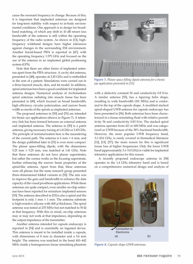
The proposed antennas in [50] and [51] are intended for bionic eye applications (shown in Figure 7). A telem-etry link has been formed between an external antenna and implanted antenna. The antenna in [50] is a patch antenna, giving necessary tuning at 1.4 GHz or 2.45 GHz. The principle of miniaturization here is the meandering of the current path. The antenna is 6 mm # 6 mm, and the design published later in [51] is even more compact. The planar space-filling dipole, with the dimensions 5.25 mm # 5.25 mm, was matched at 1.41 GHz. Note that these antennas do not have planar superstrates, but rather the cornea works as the focusing superstrate, further enhancing the narrow beam properties of the spiral-like antenna. Apart from that, these antennas were all planar, but the same research group presented three-dimensional folded variants in [52]. The aim was to improve the gain and bandwidth to enhance the data capacity of the visual prosthesis applications. While these antennas are quite compact, even smaller on-chip anten-nas have been reported for miniature implanted sensors [53]. The antenna described in [53] is also a spiral and the footprint is only 1 mm # 1 mm. The antenna substrate is high-resistive silicone with 400 n thickness. The spiral antenna was tested at 235 MHz but not matched to 50 X at that frequency. With this in mind, on-chip antennas may or may not work at that impedance, depending on the output impedance of the transmitter.
Another antenna intended for capsule endoscopy is reported in [54] and is essentially an ingested device. This antenna is meant to be installed inside a capsule, with dimensions of 8 mm in diameter and a 5.6 mm height. The antenna was matched in the band 410–442 MHz inside a homogeneous tissue simulating phantom
with a dielectric constant 56 and conductivity 0.8 S/m. A similar antenna [55], has a tapering helix shape, resulting in wide bandwidth (101 MHz) and is confor-mal to the top of the capsule shape. A modified stacked spiral-shaped UWB antenna for capsule endoscopy has been presented in [56]. Both antennas have been charac-terized in a tissue-simulating fluid with relative permit-tivity 56 and conductivity 0.83 S/m. The stacked spiral antenna operates from 411 to 600 MHz and was catego-rized as UWB because of the 38% fractional bandwidth. However, the more popular UWB frequency band, 3.1–10.6 GHz, is rarely covered in biomedical literature [12], [13], [57]; the main reason for this is significant tissue loss at higher frequencies. Only the lower UWB band (approximately 3.1–5.0 GHz) is viable for implanted telemetry applications for this reason.
A recently proposed endoscope antenna in [58] operates in the 1.4 GHz telemetry band and is based on a comprehensive numerical design and analysis of
Figure 7. Planar space-filling dipole antenna for a bionic eye application presented in [51].
(a)
connection toElectronics
(b)
connection to
Figure 8. Capsule shape UWB antennas.
80 June 2013
a conformal antenna inside the capsule. Compared to [54]–[56], the phantom models used in this study are complete and consider the presence of small intestine and other tissue materials. The proposed antenna has
good polarization characteristics that support various orientations of the capsule. An external antenna has also been proposed as in [51], but this antenna is circular polarized to efficiently capture signals with arbitrary polarizations. In [59], another spiral antenna for an ingestible capsule endoscope system has been presented. The antenna has been tested in a human phan-tom and in a pig. The antenna has successfully been used in wireless telemetry based on ON-OFF keying (OOK) modulation with 340 # 340 pixel image transmission. This design is similar to those in [55] and [56] operating at 500 MHz with bandwidths of 100 MHz.
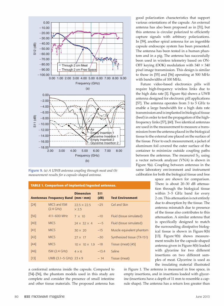
Future video-based electronics pills will require high-frequency wireless links due to the high data rate [1]. Figure 8(a) shows a UWB antenna designed for electronic pill applications [57]. The antenna operates from 3 to 5 GHz to enable a large bandwidth for a high data rate transmission and is implanted in biological tissue (beef) in order to test the propagation of the high-frequency links [57], [60]. Two identical antennas are used in the measurement to measure a trans-mission from the antenna placed in the biological tissue to the external one placed on the surface of the tissue. Prior to each measurement, a jacket of aluminum foil covered the outer surface of the container to minimize outside coupling paths between the antennas. The measured S21 using a vector network analyzer (VNA) is shown in Figure 9(a). Coupling between antennas in the same laboratory environment and instrument calibration for both the biological tissue and free
space are shown for comparison. There is about 20–30 dB attenua-tion through the biological tissue within 3–5 GHz band for every 2 cm. This attenuation is not entirely due to absorption by the tissue. The antenna mismatch due to presence of the tissue also contributes to this attenuation. A similar antenna that is specifically designed to match the surrounding dissipative biolog-ical tissue is shown in Figure 8(b) [13]. Figure 9(b) shows measure-ment results for the capsule-shaped antenna given in Figure 8(b) loaded with glycerine for two different insertions on two different sam-ples of meat. Glycerine is used as the insulating material illustrated
in Figure 1. The antenna is measured in free space, in empty insertions, and in insertions loaded with glycer-ine (insertions have a depth of 11 mm to resemble a cap-sule shape). The antenna has a return loss greater than
through 2 cm Meatthrough 2 cm Free space
Frequency (gHz)
(a)
s12
(dB
)
0.00
-10.00
-20.00
-30.00
-40.00
-50.00
-60.00
-70.00
-80.00
-90.00
-100.000.00 1.00 2.00 3.00 4.00 5.00 6.00 7.00 8.00 9.00
Empty insertion 1glycerine insertion 1Empty insertion 2glycerine insertion 2
air
s11
(dB
)
0.00
-2.00
-4.00
-6.00
-8.00
-10.00
-12.00
-14.00
-16.00
-18.002.00 3.00 4.00 5.00
Frequency (gHz)
(b)
6.00 7.00 8.00
Figure 9. (a) A UWB antenna coupling through meat and (b) measurement results for a capsule-shaped antenna.
TAblE 1. Comparison of implanted/ingested antennas.
Anntennas Frequency BandDimension (mm#mm)
S11 (dB) Test Environment
[24] MICS and ISM (2.4 GHz)
22.5 # 22.5 # 2.5
–25 Gel and Skin
[56] 411–600 MHz 7 # 10 –10 Fluid (tissue simulated)
[40] MICS 24 # 32 # 4 ~–5 Fluid (tissue simulated)
[41] MICS 30 # 20 –15 Muscle equivalent phantom
[42] MICS 27 # 17 –30 Synthesized tissue (TX-151)
[44] MICS 10 # 10 # 1.9 –18 Tissue (meat) [45]
[46] ISM (2.4 GHz) 4 # 6 –13.4 Saline
[13] UWB (3.1–5 GHz) 23 x 9 – 14 Tissue (meat)
June 2013 81
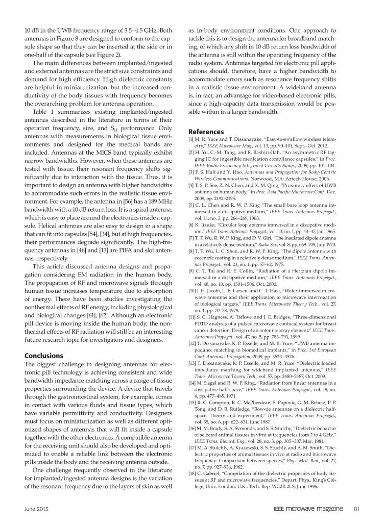
10 dB in the UWB frequency range of 3.5–4.5 GHz. Both antennas in Figure 8 are designed to conform to the cap-sule shape so that they can be inserted at the side or in one-half of the capsule (see Figure 2).
The main differences between implanted/ingested and external antennas are the strict size constraints and demand for high efficiency. High dielectric constants are helpful in miniaturization, but the increased con-ductivity of the body tissues with frequency becomes the overarching problem for antenna operation.
Table 1 summarizes existing implanted/ingested antennas described in the literature in terms of their operation frequency, size, and S11 performance. Only antennas with measurements in biological tissue envi-ronments and designed for the medical bands are included. Antennas at the MICS band typically exhibit narrow bandwidths. However, when these antennas are tested with tissue, their resonant frequency shifts sig-nificantly due to interaction with the tissue. Thus, it is important to design an antenna with higher bandwidths to accommodate such errors in the realistic tissue envi-ronment. For example, the antenna in [56] has a 189 MHz bandwidth with a 10 dB return loss. It is a spiral antenna, which is easy to place around the electronics inside a cap-sule. Helical antennas are also easy to design in a shape that can fit into capsules [54], [34], but at high frequencies, their performances degrade significantly. The high-fre-quency antennas in [46] and [13] are PIFA and slot anten-nas, respectively.
This article discussed antenna designs and propa-gation considering EM radiation in the human body. The propagation of RF and microwave signals through human tissue increases temperature due to absorption of energy. There have been studies investigating the nonthermal effects of RF energy, including physiological and biological changes [61], [62]. Although an electronic pill device is moving inside the human body, the non-thermal effects of RF radiation will still be an interesting future research topic for investigators and designers.
ConclusionsThe biggest challenge in designing antennas for elec-tronic pill technology is achieving consistent and wide bandwidth impedance matching across a range of tissue properties surrounding the device. A device that travels through the gastrointestinal system, for example, comes in contact with various fluids and tissue types, which have variable permittivity and conductivity. Designers must focus on miniaturization as well as different opti-mized shapes of antennas that will fit inside a capsule together with the other electronics. A compatible antenna for the receiving unit should also be developed and opti-mized to enable a reliable link between the electronic pills inside the body and the receiving antenna outside.
One challenge frequently observed in the literature for implanted/ingested antenna designs is the variation of the resonant frequency due to the layers of skin as well
as in-body environment conditions. One approach to tackle this is to design the antenna for broadband match-ing, of which any shift in 10 dB return loss bandwidth of the antenna is still within the operating frequency of the radio system. Antennas targeted for electronic pill appli-cations should, therefore, have a higher bandwidth to accommodate errors such as resonance frequency shifts in a realistic tissue environment. A wideband antenna is, in fact, an advantage for video-based electronic pills, since a high-capacity data transmission would be pos-sible within in a larger bandwidth.
References [1] M. R. Yuce and T. Dissanayake, “Easy-to-swallow wireless telem-
etry,” IEEE Microwave Mag., vol. 13, pp. 90–101, Sept.–Oct. 2012. [2] H. Yu, C.-M. Tang, and R. Bashirullah, “An asymmetric RF tag-
ging IC for ingestible medication compliance capsules,” in Proc. IEEE Radio Frequency Integrated Circuits Symp., 2009, pp. 101–104.
[3] P. S. Hall and Y. Hao, Antennas and Propagation for Body-Centric Wireless Communications. Norwood, MA: Artech House, 2006.
[4] T. S. P. See, Z. N. Chen, and X. M. Qing, “Proximity effect of UWB antenna on human body,” in Proc. Asia Pacific Microwave Conf., Dec. 2009, pp. 2192–2195.
[5] C. L. Chen and R. W. P. King “The small bare loop antenna im-mersed in a dissipative medium,” IEEE Trans. Antennas Propagat., vol. 11, no. 3, pp. 266–269, 1963.
[6] K. Iizuka, “Circular loop antenna immersed in a dissipative medi-um,” IEEE Trans. Antennas Propagat., vol. 13, no. 1, pp. 43–47, Jan. 1965.
[7] T. T. Wu, R. W. P. King, and D. V. Giri, “The insulated dipole antenna in a relatively dense medium,” Radio Sci., vol. 8, pp. 669–709, July 1973.
[8] T. T. Wu, L. C. Shen, and R. W. P. King, “The dipole antenna with eccentric coating in a relatively dense medium,” IEEE Trans. Anten-nas Propagat., vol. 23, no. 1, pp. 57–62, 1975.
[9] C. T. Tai and R. E. Collin, “Radiation of a Hertzian dipole im-mersed in a dissipative medium,” IEEE Trans. Antennas Propagat., vol. 48, no. 10, pp. 1501–1506, Oct. 2000.
[10] J. H. Jacobi, L. E. Larsen, and C. T. Hast, “Water-immersed micro-wave antennas and their application to microwave interrogation of biological targets,” IEEE Trans. Microwave Theory Tech., vol. 27, no. 1, pp. 70–78, 1979.
[11] S. C. Hagness, A. Taflove, and J. E. Bridges, “Three-dimensional FDTD analysis of a pulsed microwave confocal system for breast cancer detection: Design of an antenna-array element,” IEEE Trans. Antennas Propagat., vol. 47, no. 5, pp. 783–791, 1999.
[12] T. Dissanayake, K. P. Esselle, and M. R. Yuce, “UWB antenna im-pedance matching in biomedical implants,” in Proc. 3rd European Conf. Antennas Propagation, 2009, pp. 3523–3526.
[13] T. Dissanayake, K. P. Esselle, and M. R. Yuce, “Dielectric loaded impedance matching for wideband implanted antennas,” IEEE Trans. Microwave Theory Tech., vol. 57, pp. 2480–2487, Oct. 2009.
[14] M. Siegel and R. W. P. King, “Radiation from linear antennas in a dissipative half-space,” IEEE Trans. Antennas Propagat., vol. 19, no. 4, pp. 477–485, 1971.
[15] R. C. Compton, R. C. McPherdran, S. Popovic, G. M. Rebeiz, P. P. Tong, and D. B. Rutledge, “Bow-tie antennas on a dielectric half-space: Theory and experiment,” IEEE Trans. Antennas Propagat., vol. 35, no. 6, pp. 622–631, June 1987.
[16] M. M. Brady, S. A. Symonds, and S. S. Stulchy, “Dielectric behavior of selected animal tissues in vitro at frequencies from 2 to 4 GHz,” IEEE Trans. Biomed. Eng., vol. 28, no. 3, pp. 305–307, Mar. 1981.
[17] M. A. Stulchly, A. Krazewski, S. S. Stuchly, and A. M. Smith, “Die-lectric properties of animal tissues in vivo at radio and microwave frequency: Comparison between species,” Phys. Med. Biol., vol. 27, no. 7, pp. 927–936, 1982.
[18] C. Gabriel, “Compilation of the dielectric properties of body tis-sues at RF and microwave frequencies,” Depart. Phys., King's Col-lege, Univ. London, U.K., Tech. Rep. WC2R 2LS, June 1996.
82 June 2013
[19] A. W. Guy, “Analyses of electromagnetic fields induced in biologi-cal tissue by thermographic studies on equivalent phantom models,” IEEE Trans. Microwave Theory Tech., vol. 19, no. 2, pp. 205–214, 1968.
[20] M. Bini, A. Ingesti, L. Millanta, R. Olmi, N. Rubino, and R. Vanni, “The polyacrylamide as a phantom material for electromagnetic hyperthermia studies,” IEEE Trans. Biomed. Eng., vol. 31, no. 3, pp. 317–322, 1984.
[21] D. Andreucetti, M. Bini, A. Ingesti, R. Olmi, N. Rubino, and R. Vanni, “Use of polyacrylamide as a tissue-equivalent material in the microwave range,” IEEE Trans. Biomed. Eng., vol. 35, no. 4, pp. 275–277, Apr. 1988.
[22] C.-K. Chou, G.-W. Chen, A. W. Guy, and K. H. Luk, “Formulas for preparing phantom muscle tissue at various radiofrequencies,” Bioelectromagnetics, vol. 5, no. 4, pp. 435–441, 1984.
[23] G. C. Walker, E. Berry, S. W. Smye, and D. S. Brettle, “Materials for phantoms for terahertz pulsed imaging,” Phys. Med. Biol., vol. 49, no. 21, pp. N363–N369, 2004.
[24] T. Karacolak, A. Z. Hood, and E. Topsakal, “Design of a dual-band implantable antenna and development of skin mimicking gels for continuous glucose monitoring,” IEEE Trans. Microwave Theory Tech., vol. 56, no. 4, pp. 1008–1008, Apr. 2008.
[25] T. Yilmaz, T. Karacolak, and E. Topsakal, “Characterization and testing of a skin mimiking material for implantable antennas oper-ating at ISM band (2.4-2.48 GHz),” IEEE Antennas Wireless Propagat. Lett., vol. 7, pp. 418–420, June 2008.
[26] H. Tamura, Y. Ishikawa, T. Kobayashi, and T. Nojima, “A dry phan-tom material composed of ceramic and graphite powder,” IEEE Trans. Electromagn. Compat., vol. 39, no. 2, pp. 132–173, May 1997.
[27] J. T. Chang, M. W. Fanning, P. M. Meaney, and K. D. Paulsen, “A conductive plastic for simulating biological tissue at microwave frequencies,” IEEE Trans. Electromagn. Compat., vol. 42, no. 1, pp. 76–81, 2000.
[28] S. Nishizawa and O. Hashimoto, “Effectiveness analysis of lossy dielectric shields for a three-layered human model,” IEEE Trans. Microwave Theory Tech., vol. 47, no. 3, pp. 277–283, 1999.
[29] C. H. Durney, “Electromagnetic dosimetry for models of humans and animals: A review of theoretical and numerical techniques,” in Proc. IEEE, vol. 68, pp. 33–40, Jan. 1980.
[30] M. Klemm and G. Troester, “EM energy absorption in the human body tissues due to UWB antennas,” Prog. Electromagn. Res., vol. Pier 62, pp. 261–280, July 2006.
[31] O. Kivekas, T. Lehtiniemi, and P. Vainikainen, “On the general energy-absorption mechanism in the human tissue,” Microwave Opt. Technol. Lett., vol. 43, no. 3, pp. 195–201, Nov. 5, 2004.
[32] S. K. S. Gupta, S. Lalwani, Y. Prakash, E. Elsharawy, and L. Schwiebert, “Towards a propagation model for wireless biomedi-cal applications,” in Proc. IEEE Int. Conf. Communications, May 2003, vol. 3, pp. 1993–1997.
[33] J. Kim and Y. Rahmat-Samii, Implanted Antennas in Medical Wire-less Communications. San Rafael, CA: Morgan and Claypool, 2006.
[34] L. C. Chirva, P. A. Hammond, S. Roy, and D. R. S. Cumming, “Electromagnetic radiation from ingested sources in the human intestine between 150 MHz and 1.2 GHz,” IEEE Trans. Biomed. Eng., vol. 50, no. 4, pp. 484–492, Apr. 2003.
[35] L. C. Chirva, P. A. Hammond, S. Roy, and D. R. S. Cumming, “Ra-diation from ingested wireless devices in biomedical telemetry bands,” Electron. Lett., vol. 39, pp. 178–179, 23 Jan. 2003.
[36] National Library Medicine’s Visible Human Project. (2013, March). [Online]. Available: http://www.nlm.nih.gov/research/visible/
[37] A. Alomainy and Y. Hao, “Modeling and characterization of biotelemetric radio channel from ingested implants considering organ contents,” IEEE Trans. Antennas Propagat., vol. 57, no. 4, pp. 999–1005, 2009.
[38] VD6725, STMicroelectronics, Geneva, Switzerland, Jan. 2012. [39] Small Battery Company. (2012). Hearing aid batteries. [Online].
Available: http://www.smallbattery.company.org.uk/hearing_aid_batteries.htm
[40] J. Kim and Y. Rahmat-Samii, “Implanted antennas inside a hu-man body: Simulations, designs, and characterizations,” IEEE Trans. Microwave Theory Tech., vol. 52, no. 3, pp. 1934–1943, 2004.
[41] T. Houzen, M. Takahashi, K. Saito, and K. Ito, “Implanted planar inverted F-antenna for cardiac pacemaker system,” in Proc. IEEE
Int. Workshop Antenna Technology (iWAT): Small Antennas Novel Metamaterials, Chiba, Japan, 2008, pp. 346–349.
[42] P. Soontornpipit, C. M. Eurse, and Y. C. Chung, “Design of implantable microstrip antenna for communication with medical implants,” IEEE Trans. Microwave Theory Tech., vol. 52, no. 8, pp. 1944–1955, Aug. 2004.
[43] P. Soontornpipit, C. M. Furse, and Y. C. Chung, “Miniaturized biocompatible microstrip antenna using genetic algorithm,” IEEE Trans. Antennas Propagat., vol. 53, no. 6, pp. 1939–1945, 2005.
[44] W.-C. Liu, F.-M. Yeh, and M. Ghavami, “Miniaturized implant-able broadband antenna for biotelemetry communication,” Micro-wave Opt. Technol. Lett., vol. 50, no. 9, pp. 2407–2409, Jan. 2008.
[45] A. Laskovski and M. R. Yuce, “A MICS telemetry implant pow-ered by a 27MHz ISM inductive link,” in Proc. Int. Conf. IEEE Engi-neering Medicine Biology Society., Aug. 2011, pp. 2909–2912.
[46] R. Warty, M. R. Tofighi, U. Kawoos, and A. Rosen, “Characteriza-tion of implantable antennas for intracranial pressure monitoring: Reflection by and transmission through a scalp phantom,” IEEE Trans. Microwave Theory Tech., vol. 56, pp. 2366–2376, Oct. 2008.
[47] M. Z. Azad and M. Ali, “A miniature implanted inverted-F an-tenna for GPS application,” IEEE Trans. Antennas Propagat., vol. 57, no. 6, pp. 1854–1858, June 2009.
[48] H. Usui, M. Takahashi, and K. Ito, “Radiation characteristics of an implanted cavity slot antenna into the human body,” in Proc. IEEE Antennas Propagation Society Int. Symp., July 2006, pp. 1095–1098.
[49] S. Jacobsen, H. O. Rolfsnes, and P. R. Stauffer, “Characteristics of microstrip muscle-loaded single-arm archimedean spiral anten-nas as investigated by FDTD numerical computations,” IEEE Trans. Biomed. Eng., vol. 52, no. 2, pp. 321–330, 2005.
[50] K. Gosalia, G. Lazzi, and M. S. Humayun, “Investigation of mi-crowave data telemetry link for retinal prosthesis,” IEEE Trans. Mi-crowave Theory Tech., vol. 52, no. 8, pp. 1925–1933, 2004.
[51] K. Gosalia, M. S. Humayun, and G. Lazzi, “Impedance matching and implementation of planar space-filling dipoles as intraocular implanted antennas in a retinal prosthesis,” IEEE Trans. Antennas Propagat., vol. 53, no. 8, pp. 2365–2373, Aug. 2005.
[52] S. Soora, K. Gosalia, M. S. Humayan, and G. Lazzi, “A comparison of two and three dimensional dipole antennas for an implantable retinal prosthesis,” IEEE Trans. Antennas Propagat., vol. 56, no. 3, pp. 622–629, 2008.
[53] R. N. Simons and F. A. Miranda, “Radiation characteristics of miniature silicon square spiral chip antenna for implantable bio-MEMS sensors,” in Proc. IEEE Antennas Propagation Society Int. Symp. 2005, vol. 1B, pp. 836–839.
[54] S. Kwak, K. Chang, and Y. J. Yoon, “The helical antenna for the capsule endoscope,” in Proc. IEEE Antenna Propagation Society Int. Symp., July 2005, pp. 804–807.
[55] S. H. Lee, K. Chang, K. J. Kim, and Y. J. Yoon, “A conical spiral antenna for wideband capsule endoscope system,” in Proc. IEEE Antennas Propagation Society Int. Symp., San Diego, CA, USA, pp. 1–4, July 2008.
[56] S. H. Lee and Y. J. Yoon, “A dual spiral antenna for ultra-wideband capsule endoscope system” in Proc. Int. Workshop Antenna Technol-ogy: Small Antennas Novel Metamaterial, iWAT 2008, pp. 227–230.
[57] T. Dissanayake, M. R. Yuce, and C. Ho, “Design and evaluation of a compact antenna for implant-to-air UWB communication,” IEEE Antennas Wireless Propagat. Lett., vol. 8, pp. 153–156, 2009.
[58] P. M. Izdebski, H. Rajagopalan, and Y. Rahmat-Samii, “Conformal ingestible capsule antenna: A novel chandelier meandered design,” IEEE Trans. Antennas Propagat., vol. 57, no. 4, pp. 900–909, Apr. 2009.
[59] S. H. Lee, J. Lee, Y. J. Yoon, S. Park, C. Cheon, K. Kim, and S. Nam, “A wideband spiral antenna for ingestible capsule endoscope sys-tems: Experimental results in a human phantom and a pig,” IEEE Trans. Biomed. Eng., vol. 58, pp. 1734–1741, June 2011.
[60] M. R. Yuce, T. Dissanayake, and H. C. Keong, “Wireless telem-etry for electronic pill technology,” in Proc. IEEE Conf. Sensors, Oct. 2009, pp. 1433–1438.
[61] A. Kumar, “Gauge non-thermal effects of microwave fields,” Mi-crowaves and RF, vol. 41, no. 9, pp. 72–84, 2002.
[62] F. S. Barnes and B. Greenebaum, Handbook of Biological Effects of Electromagnetic Fields: Bioengineering and Biophysical Aspects of Elec-tromagnetic Fields. Boca Raton, FL: CRC Press, 2007.