Building a C-based processor - Fabien Sanglard
68
Building a C-based processor S. Woutersen Software Technology Information Technology & Systems TU Delft December, 2005
Transcript of Building a C-based processor - Fabien Sanglard

Building a C-based processor
S. Woutersen
Software TechnologyInformation Technology & Systems
TU Delft
December, 2005
Abstract
Until today every compiler has been developed by the idea to modify source codein such a way the hardware can understand it. Over the years this has resultedin inefficient processors caused by backwards compatibility issues, strange as-sembly code constructions caused by the lack of required instructions and niceinstructions supported by hardware, but never used by the software.
This research reverses the original design process. It starts by analyzing Ccode and starts working from there to a processing unit, thus supporting a min-imal amount of instructions required to run C and no backward compatibilitywith other processing units.
To limit the design time, several existing retargetable C compilers are an-alyzed whether they have a useful intermediate language which is completelyhardware independent. The LCC compilers LCC Bytecode was found to be themost acceptable language, even though a few modifications must be made to beable to efficiently run the code.
The next step is to convert the generated LCC Bytecode into a binary lan-guage. This is done by a standard set of programs including an assembler anda linker. This is the first time some input about the processing unit is required,since neither C nor LCC Bytecode specifies anything about, for example, opcodeencoding, while this can make a big difference in execution performance. Fornow the encoding is simply “guessed” and remains open for future modifications.
The last step in the chain is the actual processing unit. A software interpreterprogrammed in C is build to extensively test compiled programs, and to comparethe results with other existing solutions, such as the MIPS R2000, the Intel 386Architecture and the Intel 8051.
Test results show that LCC Bytecode is a fine language which covers C com-pletely. However some modifications where necessary to execute the code effi-ciently. The number of instructions required by LCC Bytecode is much smallerthan those supported by most current processors, and therefore, a less complex,and thus cheaper and more reliable, processor design is possible. In terms ofspeed it is found that on average more instructions per C program are requiredthan when using, for example, the MIPS instruction set, the processor will thusprobably be slower than most traditional processors.

Contents
1 Introduction 6
2 Generating assembly code 72.1 Compilers . . . . . . . . . . . . . . . . . . . . . . . . . . . . . . . 7
2.1.1 GCC . . . . . . . . . . . . . . . . . . . . . . . . . . . . . . 82.1.2 LCC . . . . . . . . . . . . . . . . . . . . . . . . . . . . . . 82.1.3 SDCC . . . . . . . . . . . . . . . . . . . . . . . . . . . . . 9
2.2 Conclusion . . . . . . . . . . . . . . . . . . . . . . . . . . . . . . 9
3 LCC bytecode 103.1 Directives . . . . . . . . . . . . . . . . . . . . . . . . . . . . . . . 10
3.1.1 Segments . . . . . . . . . . . . . . . . . . . . . . . . . . . 113.1.2 Functions . . . . . . . . . . . . . . . . . . . . . . . . . . . 113.1.3 Debug information . . . . . . . . . . . . . . . . . . . . . . 13
3.2 Instructions . . . . . . . . . . . . . . . . . . . . . . . . . . . . . . 133.2.1 Labels . . . . . . . . . . . . . . . . . . . . . . . . . . . . . 143.2.2 Loading and storing variables . . . . . . . . . . . . . . . . 143.2.3 Calling to and returning from functions . . . . . . . . . . 163.2.4 Arithmetic operators . . . . . . . . . . . . . . . . . . . . . 183.2.5 Program jumps . . . . . . . . . . . . . . . . . . . . . . . . 193.2.6 Variable type conversions . . . . . . . . . . . . . . . . . . 203.2.7 Structures . . . . . . . . . . . . . . . . . . . . . . . . . . . 21
3.3 Shortcommings . . . . . . . . . . . . . . . . . . . . . . . . . . . . 213.3.1 The LABEL instruction . . . . . . . . . . . . . . . . . . . 213.3.2 The ARG instruction . . . . . . . . . . . . . . . . . . . . 223.3.3 Structures . . . . . . . . . . . . . . . . . . . . . . . . . . . 223.3.4 Debug information . . . . . . . . . . . . . . . . . . . . . . 223.3.5 Not using the return value . . . . . . . . . . . . . . . . . . 22
4 Implementation 244.1 Overview . . . . . . . . . . . . . . . . . . . . . . . . . . . . . . . 244.2 The LCC bytecode generator . . . . . . . . . . . . . . . . . . . . 24
4.2.1 Debug symbols . . . . . . . . . . . . . . . . . . . . . . . . 264.2.2 Updating LCC . . . . . . . . . . . . . . . . . . . . . . . . 27
4.3 The bytecode converter . . . . . . . . . . . . . . . . . . . . . . . 284.4 The assembler . . . . . . . . . . . . . . . . . . . . . . . . . . . . . 284.5 The linker . . . . . . . . . . . . . . . . . . . . . . . . . . . . . . . 29
4.5.1 Bootstrap code . . . . . . . . . . . . . . . . . . . . . . . . 29
1

CONTENTS 2
4.5.2 Library files . . . . . . . . . . . . . . . . . . . . . . . . . . 304.6 The interpreter . . . . . . . . . . . . . . . . . . . . . . . . . . . . 30
4.6.1 The interpreter engine . . . . . . . . . . . . . . . . . . . . 314.6.2 Stack frames . . . . . . . . . . . . . . . . . . . . . . . . . 324.6.3 New instructions . . . . . . . . . . . . . . . . . . . . . . . 34
4.7 Program stack frame example . . . . . . . . . . . . . . . . . . . . 354.8 Future work . . . . . . . . . . . . . . . . . . . . . . . . . . . . . . 37
5 Test results 405.1 LCC Bytecode analysis . . . . . . . . . . . . . . . . . . . . . . . 40
5.1.1 Results of the DISCARD instruction . . . . . . . . . . . . 405.1.2 Instruction usage . . . . . . . . . . . . . . . . . . . . . . . 41
5.2 Assembly files . . . . . . . . . . . . . . . . . . . . . . . . . . . . . 425.3 Processing unit comparison . . . . . . . . . . . . . . . . . . . . . 42
6 Conclusions 44
A LCC bytecode instructions 45
B Embedding the interpreter 47B.1 Embedding the interpreter . . . . . . . . . . . . . . . . . . . . . . 47B.2 Calling a function . . . . . . . . . . . . . . . . . . . . . . . . . . . 48
B.2.1 Gathering information . . . . . . . . . . . . . . . . . . . . 48B.2.2 Preparing the call . . . . . . . . . . . . . . . . . . . . . . 49B.2.3 Making the call . . . . . . . . . . . . . . . . . . . . . . . . 49
C Source files 51C.1 Common source files . . . . . . . . . . . . . . . . . . . . . . . . . 51C.2 Converter . . . . . . . . . . . . . . . . . . . . . . . . . . . . . . . 51C.3 Assembler . . . . . . . . . . . . . . . . . . . . . . . . . . . . . . . 51C.4 Linker . . . . . . . . . . . . . . . . . . . . . . . . . . . . . . . . . 51C.5 Interpreter . . . . . . . . . . . . . . . . . . . . . . . . . . . . . . . 52C.6 Bootstrap code . . . . . . . . . . . . . . . . . . . . . . . . . . . . 52
D File formats 53D.1 Bytecode file format . . . . . . . . . . . . . . . . . . . . . . . . . 53D.2 Assembly file format . . . . . . . . . . . . . . . . . . . . . . . . . 53D.3 Code segment format . . . . . . . . . . . . . . . . . . . . . . . . . 55D.4 Library file format . . . . . . . . . . . . . . . . . . . . . . . . . . 56D.5 Executable file format . . . . . . . . . . . . . . . . . . . . . . . . 56
E User manual 59E.1 LCC . . . . . . . . . . . . . . . . . . . . . . . . . . . . . . . . . . 59E.2 Converter . . . . . . . . . . . . . . . . . . . . . . . . . . . . . . . 59E.3 Assembler . . . . . . . . . . . . . . . . . . . . . . . . . . . . . . . 59E.4 Linker . . . . . . . . . . . . . . . . . . . . . . . . . . . . . . . . . 60E.5 Interpreter . . . . . . . . . . . . . . . . . . . . . . . . . . . . . . . 60

CONTENTS 3
F Example compilation run 61F.1 C File . . . . . . . . . . . . . . . . . . . . . . . . . . . . . . . . . 61F.2 Bytecode file . . . . . . . . . . . . . . . . . . . . . . . . . . . . . 61F.3 Custimized bytecode file . . . . . . . . . . . . . . . . . . . . . . . 62F.4 Binary assembly file . . . . . . . . . . . . . . . . . . . . . . . . . 63F.5 Executable file . . . . . . . . . . . . . . . . . . . . . . . . . . . . 65
List of Tables
2.1 Compiler comparison . . . . . . . . . . . . . . . . . . . . . . . . . 9
3.1 LCC Bytecode arithmetic operators . . . . . . . . . . . . . . . . 183.2 LCC Bytecode conditional jumps . . . . . . . . . . . . . . . . . . 19
5.1 Discard instruction results . . . . . . . . . . . . . . . . . . . . . . 415.2 LCC Instruction frequency . . . . . . . . . . . . . . . . . . . . . . 415.3 Assembly file lines comparison . . . . . . . . . . . . . . . . . . . 425.4 Instruction count and size . . . . . . . . . . . . . . . . . . . . . . 43
A.1 LCC Instruction type and size suffixes . . . . . . . . . . . . . . . 45A.2 LCC Instructions . . . . . . . . . . . . . . . . . . . . . . . . . . . 46
D.1 Assembly file format . . . . . . . . . . . . . . . . . . . . . . . . . 54D.2 Label list file format . . . . . . . . . . . . . . . . . . . . . . . . . 54D.3 Label format . . . . . . . . . . . . . . . . . . . . . . . . . . . . . 54D.4 Label flags . . . . . . . . . . . . . . . . . . . . . . . . . . . . . . . 54D.5 Segment codes . . . . . . . . . . . . . . . . . . . . . . . . . . . . 55D.6 Segment format . . . . . . . . . . . . . . . . . . . . . . . . . . . . 55D.7 Instruction format . . . . . . . . . . . . . . . . . . . . . . . . . . 55D.8 Instruction type format . . . . . . . . . . . . . . . . . . . . . . . 56D.9 LCC Instructions . . . . . . . . . . . . . . . . . . . . . . . . . . . 57D.10 Library format . . . . . . . . . . . . . . . . . . . . . . . . . . . . 58
4

List of Figures
3.1 Stack frames after function entrances . . . . . . . . . . . . . . . . 133.2 Stack frames for fetching variables . . . . . . . . . . . . . . . . . 153.3 Stack frames for assigning variables . . . . . . . . . . . . . . . . . 163.4 Stack frames for calling functions . . . . . . . . . . . . . . . . . . 173.5 Stack frames for arithmetic operations . . . . . . . . . . . . . . . 18
4.1 Design path . . . . . . . . . . . . . . . . . . . . . . . . . . . . . . 254.2 Tree for z = x + y . . . . . . . . . . . . . . . . . . . . . . . . . . 254.3 Tree for z = some func() . . . . . . . . . . . . . . . . . . . . . . . 264.4 Tree for some func() . . . . . . . . . . . . . . . . . . . . . . . . . 264.5 Interpreter . . . . . . . . . . . . . . . . . . . . . . . . . . . . . . . 314.6 Stack frame step I . . . . . . . . . . . . . . . . . . . . . . . . . . 324.7 Stack frame step II . . . . . . . . . . . . . . . . . . . . . . . . . . 334.8 Stack frame step III . . . . . . . . . . . . . . . . . . . . . . . . . 334.9 Stack frame step IV . . . . . . . . . . . . . . . . . . . . . . . . . 334.10 Final stack frame layout . . . . . . . . . . . . . . . . . . . . . . . 344.11 Stack frame example Step I . . . . . . . . . . . . . . . . . . . . . 364.12 Stack frame example Step II . . . . . . . . . . . . . . . . . . . . . 364.13 Stack frame example Step III . . . . . . . . . . . . . . . . . . . . 364.14 Stack frame example Step IV . . . . . . . . . . . . . . . . . . . . 374.15 Stack frame example Step V . . . . . . . . . . . . . . . . . . . . . 374.16 Stack frame example Step VI . . . . . . . . . . . . . . . . . . . . 384.17 Stack frame example Step VII . . . . . . . . . . . . . . . . . . . . 38
5

Chapter 1
Introduction
A few decennia ago, the first compiler was launched, while today, there arethousands of compilers available for dozens of programming languages. Eventhough a lot has changed since the first compiler, one thing is still the same.The design process always started out from two different points. One groupstarted working on designing a programming language, and a complete othergroup, often much later or earlier, started working on a processing unit. Whenboth where done, a bridge, in the form of a compiler, must be build between thedesigned programming language and language supported by the processing unit.This often resulted in strange inefficient code constructions to support variousaspects of the programming language, as well as completely unused processingunit instructions.
This research takes another approach [3]. It’s starts with looking at C code,and works towards the specifications of a not yet existing processing unit. Theprocessing unit will therefore be completely be based on C, will support noinstructions C does not support, and does not need any “tricks” to run any Cprogram. The reason for this new approach is the fact that nowadays, processorsare much easier to develop, and hardware limitations are no longer a real issue.Therefore, it is now possible to base the hardware on the code it is supposed toexecute, instead of altering code in a way such that the hardware can executeit. Finally, the new processing unit, which will be designed for this researchin the form of an interpreter, will be compared to existing processing units, tofind out if this will benefit the size, complexity and speed of the new processingunit, compared to existing ones.
The second chapter of this report describes the search for a useful compiler.It looks into a few different existing compilers and compares them between eachother, and a not yet existing but maybe required, newly developed compiler.Chapter 3 documents the assembly language which is used, followed by Chapter4 which gives a detailed description on how the executable files are generated,and how the interpreter works and is created. Finally, in Chapter 5 and 6, thetest results and conclusions are given.
6
Chapter 2
Generating assembly code
When designing a processing unit to execute C code, the extreme situation wouldbe feeding the processing unit directly with C source and header files. The Clanguage however has a few properties which makes it much easier to program,but much harder to execute. A few examples of these properties are the supportfor text labels, code placement in several files, and less obvious, redundancy inC code. The for statement, for example, may just as well be programmed usingwhile or even if statements. A processing unit which can execute C code wouldthus require a complicated text parser, a lot of memory and a label resolver.Most of the work, such as label resolvement, can be done prior to executingthe code, and only has to be done once for each program. Traditionally this isall done by compilers which generate simple assembly code, assemblers whichconvert assembly code into binary files and linkers who combine several files intoone executable. Since simpler code will always result in a simpler processingunit, it is wise to stick with the traditional use of a compiler. The conversionprocess however, must be completely based on C code, and not be influencedby any knowledge about the processing platform which is eventually going toexecute the code. The compiler must thus be completely independent of thetargeted platform.
Since building a new compiler is a lot of work, this chapter mostly dealswith looking for a useful existing compiler. Several compilers are examined inthe first section of this chapter, and finally a conclusion is given which, if any,compiler would be the best choice for generating assembly code.
2.1 Compilers
Since there is a vast amount of compilers available, the search to a useful com-piler must be narrowed a lot right at the start. Only a few compilers can beexamined thoroughly, and for most compilers it can be seen in a flash whetherthey might be up to the task or absolutely not. The criteria for the compilersto be examined further are given here:
• Open source: The compiler must be open source to be able to examine itsinternals.
• Free: No money can be spent on the compiler.
7

CHAPTER 2. GENERATING ASSEMBLY CODE 8
• Portable: The compiler must be designed to be portable. This will ensurethe compiler can be used for different kind of processing units, and thus(likely) be hardware independent1.
• Documented: The compiler (and its source code) must be very well doc-umented.
• Reliable: The compiler must be reliable and work correctly.
These criteria immediately eliminate a large amount of compilers. Most small“hobby” projects are not portable or very well documented, while most commer-cial products are not open source, free or target a specific platform. However,three existing compilers seem to hold up quit nice to these criteria, and will beexamined further, namely GCC, LCC and SDCC.
These compilers will be looked into in the following sections, to see if oneof them is able to generate valid hardware independent assembly code. TheGCC, LCC and SDCC compilers are further discussed in Sections 2.1.1 to 2.1.3respectively, and a comparison is given in 2.2.
2.1.1 GCC
The GNU C Compiler is probably the most popular compiler today. It runs onalmost any system, and can create code for almost every system. Since it is sowidely used, a lot of information is available on how it works, and how to alterit if necessary. However, Nilsson [12], states:
GCC is specifically aimed at CPU’s with several 32-bit general regis-ters and byte-addressable memory. Deviations from this are possible.In short, you can make a port of GCC for a target with 16-bit regis-ters, but not a decent implementation for a processor with only onegeneral register.
This directly states that GCC is only partially hardware independent, since itneeds a register machine to operate efficiently. Internally, GCC uses a so called“Register Transfer Language” or “RTL”. First, the C code is converted intoRTL code, in which an infinite amount of available registers exists. Second, theRTL code is optimized to a specific processor, and finally, the code is convertedto processor specific assembly code. The last two steps can be stripped fromthe compiler such that RTL code is being emitted from the compiler. ThisRTL code is fairly hardware independent except for one assumption: the targetprocessing unit must be a register machine.
2.1.2 LCC
The second compiler which is tested, LCC, is designed to be a completely re-targatable compiler, no more, no less. Since any code optimization falls out ofthis project, this might be the perfect candidate. Just like GCC, LCC uses aninternal language to which C code is converted, and contains several backendswhich convert the LCC bytecode to assembly code for a specific processor. Un-like GCC RTL, LCC bytecode is based on a stack language. Since any (useful)
1This must be validated in further research

CHAPTER 2. GENERATING ASSEMBLY CODE 9
processing unit will have some random access memory available, a stack basedlanguage will not limit the design of the processing unit (apart from performanceperhaps).
A second advantage of LCC is that it’s internal bytecode can be emittedwithout changing the source of LCC at all, but simply with a command lineoption which selects the “bytecode” backend.
2.1.3 SDCC
The Small Device C Compiler is a C compiler developed specially for buildingembedded applications, which run on small processors or microcontrollers. It iscompletely open source but unfortunately not very well documented. Accordingto the SDCC programmers in [14] it is possible to build a new backend for theirprocessor, and point out a few changes on where to modify the existing compiler.No real standard retargeting procedure exists, and nobody but the programmersthemselves seems ever to have done it. Another problem with SDCC, is theoriginal design concept: it was build to be specifically a compiler for embeddedsystems, which means it had a “hardware assumption” right from the start.
2.2 Conclusion
To summarize the previous sections, a few important properties of all compilersare given here, including a mark on how well they perform, from positive (++)to negative (--).
Table 2.1: Compiler comparisonProperty GCC LCC SDCC New custom compilerDocumentation ++ + -- ++Retargetable ++ ++ - ++Internal language + ++ ? ++CPU dependency 0 + 0 ++Work to retarget 0 ++ - --Work to build CPU 0 + ? ++
From this table it can be seen that either LCC or a custom self build compilerwould be the best choice. The self build compiler wins it on every aspect becauseit can be tuned to all of these specifications; however, the double minus onwork to build the compiler is a very important one. GCC loses from LCC mostlybecause LCC bytecode files are generated much easier then GCC RTL files, andbecause LCC bytecode files can be run on any processing unit without majormodifications, while when using GCC RTL, at some point, the register count mustbe scaled down to an acceptable amount of registers. SDCC scores lowest on thischart, mostly caused by the lack of good documentation about its internals.
From this information, LCC is chosen to be the compiler, and LCC bytecodeto be the new assembly language to work with. In the following chapter, thespecifications of the LCC bytecode language are fully documented.

Chapter 3
LCC bytecode
This chapter describes the layout of the bytecode files generated by LCC andall assembler directives and instructions which may appear in the source files.The information used to make this document is gathered from Hanson andFraser [5], [6], the Quake 3 implementation of LCC Bytecode [13] and thecomp.compilers.lcc newsgroup.
LCC Bytecode consists of a set of instructions and assembler directives.All these instructions and directives are placed in a text file, one instruc-tion/directive per line. The directives are printed in lower case, while the in-structions are printed in upper case. Some directives and instructions have oneore more parameters. These parameters are separated by spaces, and all nu-merical parameters are printed in the decimal system. Note that this chapter iscompletely based on what LCC will ever generate. When building an assembler,it might be desirable to accept more then just what is described in this chapter,for example comment in bytecode files.
All directives are described in Section 3.1, all instructions in 3.2 and finally,in Section 3.3 some shortcommings of the LCC Bytecode language are discussed.
3.1 Directives
The following directives are generated by LCC:
code : segment informationlit : segment informationdata : segment informationbss : segment informationalign : segment informationbyte : segment informationskip : segment informationaddress : segment informationexport : procedure informationimport : procedure informationproc : procedure informationendproc : procedure informationfile : debug informationline : debug information
10
CHAPTER 3. LCC BYTECODE 11
All directives are printed in lower case, while all instructions are printed inupper case. The different directives fall in three main categories. First, thedirectives code, lit, data, bss, align, byte, skip and address directives allcontrol the different segments used by LCC. These are all discussed in Section3.1.1. The export, import, proc, and endproc directives contain function spe-cific information and are described in Section 3.1.2. Finally the file and linedirectives contain debug information and are described in the last section.
3.1.1 Segments
LCC supports four different segments for code and variables:
• code: All instructions are placed inside the code segment. This segmentcan be mapped onto read-only memory.
• lit: All constants (literals) are placed in the lit segment. This segmentcan also be mapped onto read-only memory.
• data: All initialized variables are placed in the data segment. This seg-ment must be mapped onto writable memory.
• bss: The BSS1 segment contains the uninitialized variables. This segmentmust also be mapped onto writable memory. No data should be stored inthe bss segment prior to execution.
In a bytecode file, the start of a new segment is noted by a single line, with justthe name of the segment. Note that some directives which apply to an itemin a specific segment, may fall outside that segment. For example; the exportdirective applies to a specific function, but it might be placed outside the codesegment.
While the code segment will merely consist of instructions, the lit and datasegment contain preset values and labels, while the bss segment contains onlylabels. The labels themselves are generated as instructions and are thereforehandled in Section 3.2.1.
LCC uses three directives to fill a segment with data. The first is byte. Thebyte directive has two decimal parameters containing the amount of bytes, andits numerical value of the data which should be added to the segment. Thebyte directive is mostly used to add constant strings. The second one is skip.This directive does not add any data to a segment, but just allocates space.The decimal parameter holds the number of bytes to be allocated. The skipdirective is used to allocate uninitialized data in the BSS space. Finally, theaddress directive loads an address in a segment. A label name is passed asparameter.
3.1.2 Functions
LCC does not create any function prologue or epilogue, instructions for buildinga function stack frame do not exist. Instead, the start and end of a function isnoted by two assembler directives, optionally combined with an export direc-tive, which denotes a function that may be called from other files;
1Block Started by Symbol, originally an opcode, nowadays used as segment name
CHAPTER 3. LCC BYTECODE 12
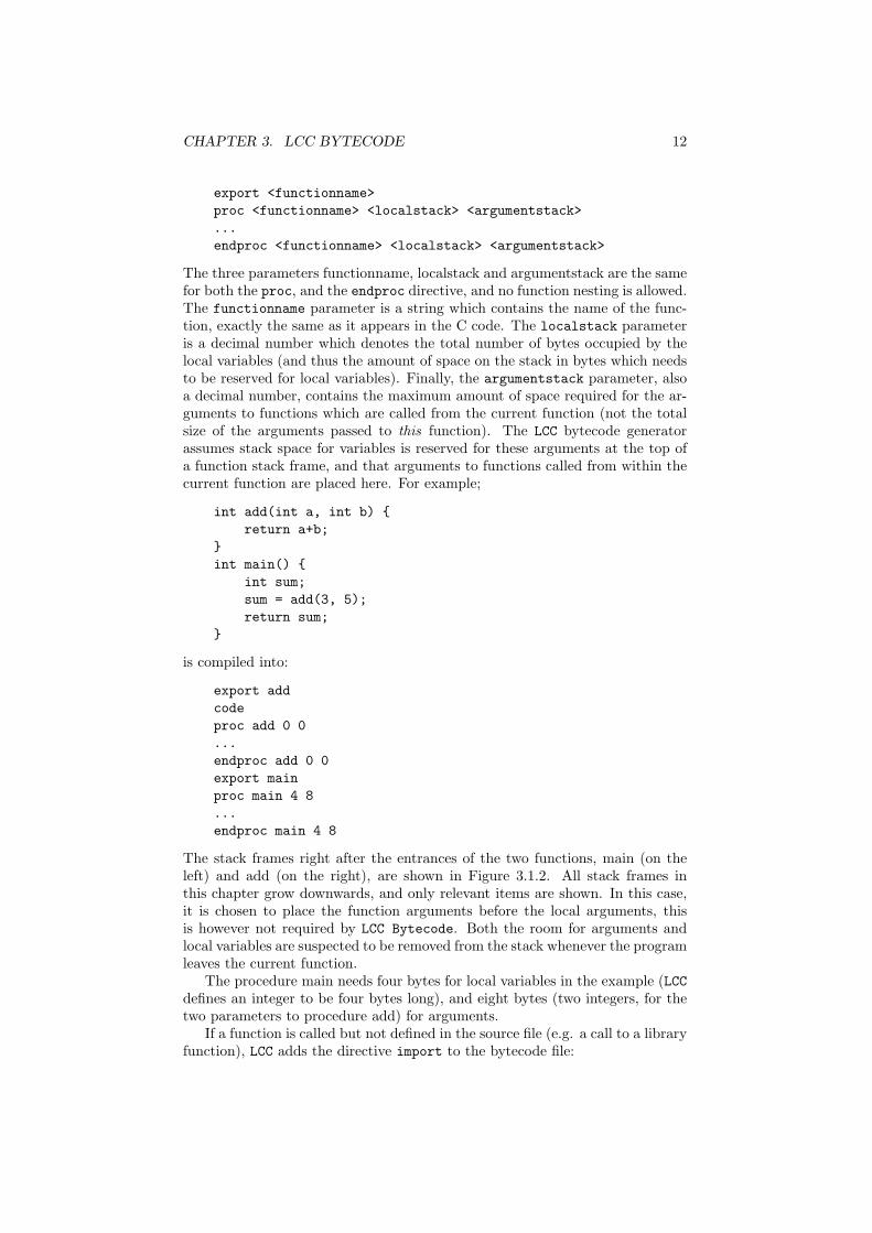
export <functionname>proc <functionname> <localstack> <argumentstack>...endproc <functionname> <localstack> <argumentstack>
The three parameters functionname, localstack and argumentstack are the samefor both the proc, and the endproc directive, and no function nesting is allowed.The functionname parameter is a string which contains the name of the func-tion, exactly the same as it appears in the C code. The localstack parameteris a decimal number which denotes the total number of bytes occupied by thelocal variables (and thus the amount of space on the stack in bytes which needsto be reserved for local variables). Finally, the argumentstack parameter, alsoa decimal number, contains the maximum amount of space required for the ar-guments to functions which are called from the current function (not the totalsize of the arguments passed to this function). The LCC bytecode generatorassumes stack space for variables is reserved for these arguments at the top ofa function stack frame, and that arguments to functions called from within thecurrent function are placed here. For example;
int add(int a, int b) {return a+b;
}int main() {
int sum;sum = add(3, 5);return sum;
}
is compiled into:
export addcodeproc add 0 0...endproc add 0 0export mainproc main 4 8...endproc main 4 8
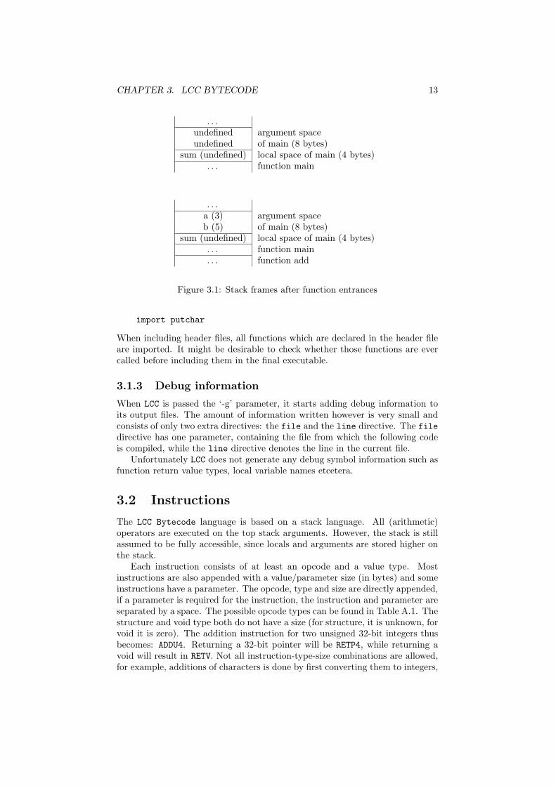
The stack frames right after the entrances of the two functions, main (on theleft) and add (on the right), are shown in Figure 3.1.2. All stack frames inthis chapter grow downwards, and only relevant items are shown. In this case,it is chosen to place the function arguments before the local arguments, thisis however not required by LCC Bytecode. Both the room for arguments andlocal variables are suspected to be removed from the stack whenever the programleaves the current function.
The procedure main needs four bytes for local variables in the example (LCCdefines an integer to be four bytes long), and eight bytes (two integers, for thetwo parameters to procedure add) for arguments.
If a function is called but not defined in the source file (e.g. a call to a libraryfunction), LCC adds the directive import to the bytecode file:
CHAPTER 3. LCC BYTECODE 13
. . .undefined argument spaceundefined of main (8 bytes)
sum (undefined) local space of main (4 bytes). . . function main
. . .a (3) argument spaceb (5) of main (8 bytes)
sum (undefined) local space of main (4 bytes). . . function main. . . function add
Figure 3.1: Stack frames after function entrances
import putchar
When including header files, all functions which are declared in the header fileare imported. It might be desirable to check whether those functions are evercalled before including them in the final executable.
3.1.3 Debug information
When LCC is passed the ‘-g’ parameter, it starts adding debug information toits output files. The amount of information written however is very small andconsists of only two extra directives: the file and the line directive. The filedirective has one parameter, containing the file from which the following codeis compiled, while the line directive denotes the line in the current file.
Unfortunately LCC does not generate any debug symbol information such asfunction return value types, local variable names etcetera.
3.2 Instructions
The LCC Bytecode language is based on a stack language. All (arithmetic)operators are executed on the top stack arguments. However, the stack is stillassumed to be fully accessible, since locals and arguments are stored higher onthe stack.
Each instruction consists of at least an opcode and a value type. Mostinstructions are also appended with a value/parameter size (in bytes) and someinstructions have a parameter. The opcode, type and size are directly appended,if a parameter is required for the instruction, the instruction and parameter areseparated by a space. The possible opcode types can be found in Table A.1. Thestructure and void type both do not have a size (for structure, it is unknown, forvoid it is zero). The addition instruction for two unsigned 32-bit integers thusbecomes: ADDU4. Returning a 32-bit pointer will be RETP4, while returning avoid will result in RETV. Not all instruction-type-size combinations are allowed,for example, additions of characters is done by first converting them to integers,
CHAPTER 3. LCC BYTECODE 14
and do an integer addition. ADDI1 therefore will never occur, but also theMULP4 will never be generated by LCC since the multiplication of pointers is notsupported by C.
In Appendix A a table is given with all possible combinations of opcode,type and size.
3.2.1 Labels
Labels are generated by the compiler as instructions. While all other instruc-tions will only ever appear in the code segment, the LABEL instruction canoccur in any of the four segments. An example of the declaration of global 32bit integer i:
export ialign 4LABELV iskip 4
By default, the LCC aligns every variable, except for characters, by 4. The skipdirective is the directive which actually allocates the space for the variable.
3.2.2 Loading and storing variables
Within compiled programs, variables can be stored at three different locations:in the local space of a function, in the argument space of a function, and inthe global space of a program. For each of these, different instructions exist forloading and storing them.
A variable load consists of two instructions. The first one computes theaddress of the variable and puts it on top of the stack, the second one readsthe location from the stack and copies the data from the location to the top ofthe stack. The first instruction is different for variables from all three spaces:ADDRG for global variables, ADDRL for local variables and ADDRF for parameters.The variable offset is stored in the parameter of the instruction. The base offsetof local and global variables and parameters should always be known by theexecution unit (as it can not be computed in advance). When, for example,three local variables are declared, i, j and k, the variable offset for i is zero,the offset for j is the size of i, and the offset for k is the size of i plus the size ofj. The base offset in this case is the beginning of the local space of the functionin which i, j and k are defined. In case of a global variable, the parameter ofthe instruction is not numeric, but instead a string containing the name of alabel created with the LABEL instruction. In any case, the parameter may beextended by +x or -x where x is a decimal number containing an offset relativeto the first parameter:
ADDRGP variable+12
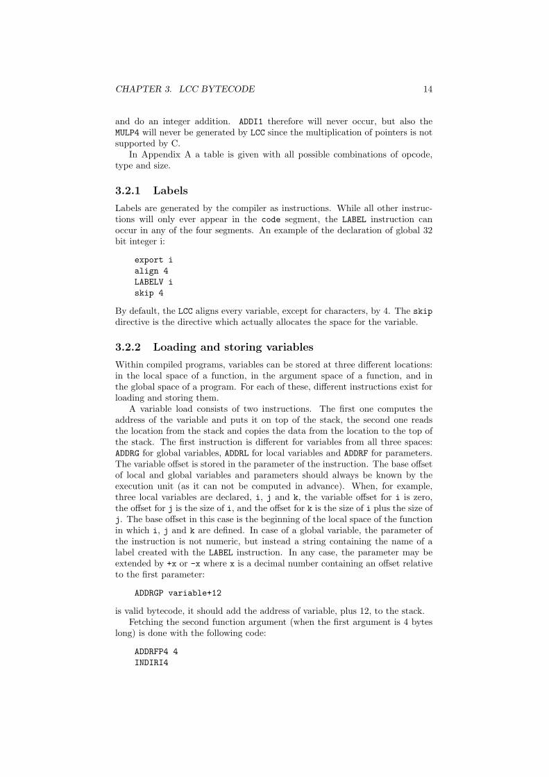
is valid bytecode, it should add the address of variable, plus 12, to the stack.Fetching the second function argument (when the first argument is 4 bytes
long) is done with the following code:
ADDRFP4 4INDIRI4
CHAPTER 3. LCC BYTECODE 15
The stack frames for this piece of code (right after the ADDRF and the INDIRinstructions) are shown in Figure 3.2.2 (which corresponds to fetching argumentb from the example used in Section 3.1.2). The ADDRF instruction computes theabsolute address of the argument, by adding 4 to the argument space offset (inthis case 0x10). The result (0x14) is stored on the stack. The INDIR instructionpops the address, and replaces it with the actual value found on this address.
. . .0x10: 3 argument space of main0x14: 50x18: sum (undefined) local space of main0x1B: . . .0x20: 0x14 address of second argument
. . .0x10: 3 argument space of main0x14: 50x18: sum (undefined)
. . .0x20: 5 value of second argument
Figure 3.2: Stack frames for fetching variables
In the same way; fetching local variable sum inside the main procedure wouldbe done with the following code:
ADDRLP4 0INDIRI4
Storing variables in the local or global space of a program is done the same way,except that the INDIR instruction is replaced by the ASGN instruction, and thevalue to store is placed on the stack right after the address. The code
ADDRLP4 0CNSTI4 10ASGNI4
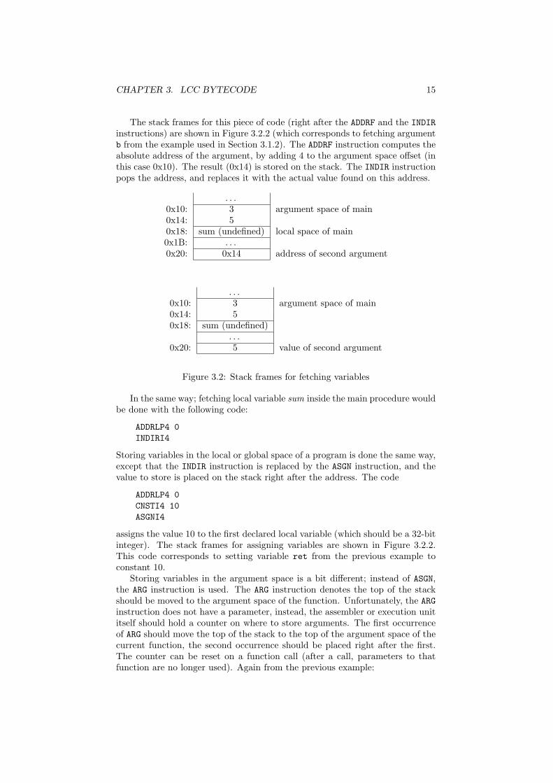
assigns the value 10 to the first declared local variable (which should be a 32-bitinteger). The stack frames for assigning variables are shown in Figure 3.2.2.This code corresponds to setting variable ret from the previous example toconstant 10.
Storing variables in the argument space is a bit different; instead of ASGN,the ARG instruction is used. The ARG instruction denotes the top of the stackshould be moved to the argument space of the function. Unfortunately, the ARGinstruction does not have a parameter, instead, the assembler or execution unititself should hold a counter on where to store arguments. The first occurrenceof ARG should move the top of the stack to the top of the argument space of thecurrent function, the second occurrence should be placed right after the first.The counter can be reset on a function call (after a call, parameters to thatfunction are no longer used). Again from the previous example:

CHAPTER 3. LCC BYTECODE 16
. . .0x10: 3 argument space of main0x14: 50x18: sum (undefined) local space of main0x1B: . . .0x28: 0x14 address of first local variable
. . .0x10: 3 argument space of main0x14: 50x18: sum (undefined) local space of main0x1B: . . .0x28: 0x18 address of first local variable0x2B: 10 value to store
. . .0x10: 3 argument space of main0x14: 50x18: sum (10)
. . .
Figure 3.3: Stack frames for assigning variables
CNSTI4 5ARGI4CNSTI4 3ARGI4
loads the constants five and three into the argument space of the proceduremain. The arguments are now ready for the function call to add (the stackframes from before and after this piece of code are similar to Figure 3.1.2).
Finally, constants, as seen in the previous example, are loaded through theCNST instruction. The parameter of this instruction will hold the constant.Floating point values are first casted to integers (such that the binary repre-sentation of the integer is the same as the binary representation of the floatingpoint number according to IEEE 754). Double precision floating point valuesare placed in two four byte integers. String constants are placed in the litsegment rather than the code segment, and are loaded using the ADDRG andINDIR instruction.
3.2.3 Calling to and returning from functions
A function call is made with the CALL instruction. CALL does not take anyparameters, instead, the address of the function is assumed to be on top of thestack. The type and size of the CALL instruction are the type and size of thereturn value. The code
CHAPTER 3. LCC BYTECODE 17
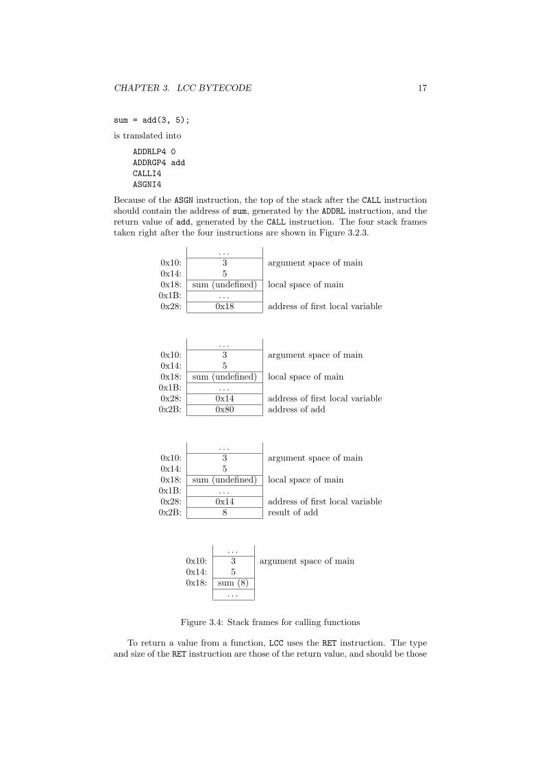
sum = add(3, 5);
is translated into
ADDRLP4 0ADDRGP4 addCALLI4ASGNI4
Because of the ASGN instruction, the top of the stack after the CALL instructionshould contain the address of sum, generated by the ADDRL instruction, and thereturn value of add, generated by the CALL instruction. The four stack framestaken right after the four instructions are shown in Figure 3.2.3.
. . .0x10: 3 argument space of main0x14: 50x18: sum (undefined) local space of main0x1B: . . .0x28: 0x18 address of first local variable
. . .0x10: 3 argument space of main0x14: 50x18: sum (undefined) local space of main0x1B: . . .0x28: 0x14 address of first local variable0x2B: 0x80 address of add
. . .0x10: 3 argument space of main0x14: 50x18: sum (undefined) local space of main0x1B: . . .0x28: 0x14 address of first local variable0x2B: 8 result of add
. . .0x10: 3 argument space of main0x14: 50x18: sum (8)
. . .
Figure 3.4: Stack frames for calling functions
To return a value from a function, LCC uses the RET instruction. The typeand size of the RET instruction are those of the return value, and should be those
CHAPTER 3. LCC BYTECODE 18
of the CALL instruction which called the function. The RET instruction uses thetop of the stack as a return value. The RET instruction must make sure the stackand processing unit control registers looks just like it was before the functioncall, but with one extra value on the stack: the return value.
Returning a constant 32-bit integer with the value 10 simply looks like this:
CNSTI4 10RETI4
Supplying a function with arguments is done by writing them to the argu-ment space as is discussed in the previous section.
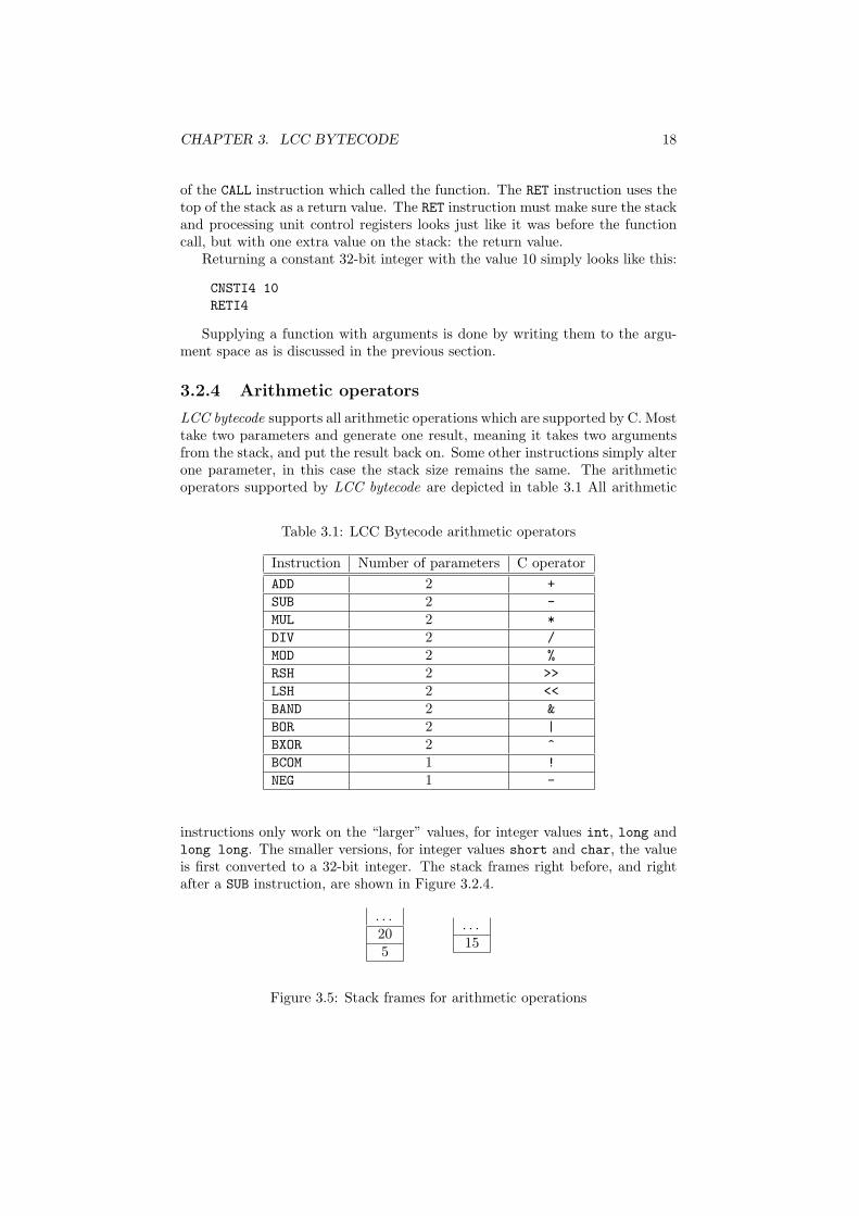
3.2.4 Arithmetic operators
LCC bytecode supports all arithmetic operations which are supported by C. Mosttake two parameters and generate one result, meaning it takes two argumentsfrom the stack, and put the result back on. Some other instructions simply alterone parameter, in this case the stack size remains the same. The arithmeticoperators supported by LCC bytecode are depicted in table 3.1 All arithmetic
Table 3.1: LCC Bytecode arithmetic operators
Instruction Number of parameters C operatorADD 2 +SUB 2 -MUL 2 *DIV 2 /MOD 2 %RSH 2 >>LSH 2 <<BAND 2 &BOR 2 |BXOR 2 ^BCOM 1 !NEG 1 -
instructions only work on the “larger” values, for integer values int, long andlong long. The smaller versions, for integer values short and char, the valueis first converted to a 32-bit integer. The stack frames right before, and rightafter a SUB instruction, are shown in Figure 3.2.4.
. . .205
. . .15
Figure 3.5: Stack frames for arithmetic operations

CHAPTER 3. LCC BYTECODE 19
3.2.5 Program jumps
No program could exist without the help of (conditional) jumps. LCC bytecodesupports seven types of jumps, six conditional and one unconditional.
The unconditional jump, the JUMP instruction and has no parameter. Theaddress to which to jump is instead taken from the top of the stack. The sixconditional jumps are depicted in table 3.2 They all have one parameter which
Table 3.2: LCC Bytecode conditional jumps
Instruction C operatorEQ ==GE >=GT >LE <=LT <NE !=
contains a label to jump through if the condition evaluates to positive. The twoparameters of the condition are taken from the top of the stack.
CNSTI4 3CNSTI4 4GE SOMELABEL
Will not jump to SOMELABEL. However:
CNSTI4 3CNSTI4 4NE SOMELABEL
will. All if statements, while loops, for loops, etc. will result in a bytecodeconstruction which uses one or more (conditional) jumps. LCC will, if necessary,add extra labels named as a dollar sign followed by an unique number. Forexample, the following code:
01: int max(int a, int b) {02: int ret;03: if (a > b) {04: ret = a;05: } else {06: ret = b;07: }08: return ret;09: }
will compile into:
proc max 4 0line 1line 3

CHAPTER 3. LCC BYTECODE 20
ADDRFP4 0INDIRI4ADDRFP4 4INDIRI4LEI4 $2line 4ADDRLP4 0ADDRFP4 0INDIRI4ASGNI4line 5ADDRGP4 $3JUMPVLABELV $2line 6ADDRLP4 0ADDRFP4 4INDIRI4ASGNI4line 7LABELV $3line 8ADDRLP4 0INDIRI4RETI4LABELV $1endproc max 4 0
3.2.6 Variable type conversions
The last set of instructions handles the conversions of different variable types.These include the conversion from one type to a larger or smaller version of thesame type, or the conversion between types. Instructions generated by LCC toconvert types are called CV*, where * stands for the type it is being convertedfrom. This can be F for floating point, I for signed integer, P for pointer andU for unsigned integer. The type and size of the instruction denote the typeand size of the value it needs to be converted to. The size of the value beforeit is converted is stored in the instructions parameter. Conversion instructionsalways convert the value placed on top of the stack.
Not all conversions are supported. Converting one type to another may re-quire multiple conversions. The possible combinations can be found in AppendixA.
Several conversions are displayed here:
signed char to int:CVII4 1signed char to float:CVII4 1CVIF4 4

CHAPTER 3. LCC BYTECODE 21
pointer to double:CVPU4 4CVUI4 4CVIF8 4
(note that pointer to double conversion is not directly supported by C, however,if it would, it would look like this)
3.2.7 Structures
Structures in LCC Bytecode are not separated in several primitives, but con-sidered a special type. Only a few instructions can have the structure type, ascan be seen in Table A.2, these instructions are INDIR, ASGN, ARG, CALL andRET. However, LCC supports not passing structures to, and not returning themfrom functions. Instead, pointers to structures are passed. Since this option isdefault turned on, the ARGB, CALLB and RETB instructions will never appear inbytecode files.
The INDIR and ASGN instructions are only used to copy one structure toanother. Every occurrence of INDIR will be followed by an ASGN instruction.Copying a 16 byte global structure a to another global structure named b lookslike this:
ADDRG bADDRG aINDIRBASGNB 16
Note that the size of the structure is only given as parameter of the ASGN in-struction.
LCC Requires that the first values within a structure also get the lowestmemory addresses, since LCC uses pointer additions to compute the addressesof different values within structures.
3.3 Shortcommings
Unfortunately, LCC Bytecode has a few small shortcommings which makes itimpossible, hard or just inefficient to run on a processing unit. It’s very impor-tant to keep track of these shortcommings when building a processing unit forLCC Bytecode. Most of them can very simply be fixed by modifying the existingLCC backend, or by modifying the bytecode files slightly after they are generatedby LCC. In the following paragraphs, each of these problems are discussed, aswell as one ore more methods to fix them.
3.3.1 The LABEL instruction
The LABEL instruction is for some reason implemented as an instruction insteadof a directive as it should be. No processing unit will ever do something when itencounters a LABEL instruction, instead, the information the instruction holdsshould be used by the assembler and or linker.

CHAPTER 3. LCC BYTECODE 22
3.3.2 The ARG instruction
The ARG instruction is used to place an argument in the argument block topass it to a function. However the ARG instruction has no argument denotingthe location (or parameter index). Therefore, any processing unit must havean extra counter to keep track on where to place arguments, while this canbe solved a lot easier by giving the ARG instruction a parameter containing itslocation.
3.3.3 Structures
LCC Bytecode has its own type for structures. Therefore, structures of infinitelarge size are copied with only one instruction. This will be impossible toimplement on any hardware system, but it is the only possible way to keepmoving structures around hardware independent. This must most likely bechanged when hardware specifications are available.
The real problem with structures is the fact that a structure copy is done bytwo instructions: INDIR, which fetches the structure and ASGN, which writes thestructure to another location. However the size of the structure is not known(the B type never has a size). For the ASGN instruction, this is solved by addingthe size of the structure as a parameter, however this is not done for the INDIRinstruction. A structure copy of a 16 byte structure thus looks like this:
INDIRBASGNB 16
This is a problem since the size of the structure must be known when fetchingit from the memory (by the INDIR instruction). Since each INDIRB is followedby a ASGNB instruction, the assembler should look ahead when it encounters theINDIRB to find the size the INDIRB instruction should work on.
3.3.4 Debug information
Although LCC does support the ’-g’ parameter, hardly any debugging informa-tion is generated. When debugging is turned on, two new directives are addedto the bytecode files: file and line, which are described in Section 3.1. To beable to efficiently debug programs, much more information is required.
3.3.5 Not using the return value
There is one shortcomming of the LCC bytecode that can actually be considereda bug in LCC. Consider the following peace of code:
int add(int a, int b) {return a + b;
}int main(int argc, char** argv) {
add(1,2);return 0;
}
which is perfectly good C code. The bytecode generated for this peace of codelooks like this:

CHAPTER 3. LCC BYTECODE 23
proc add 0 0...RETI4endproc add 0 0proc main 0 8...ADDRGP4 addCALLI4CNSTI4 0RETI4endproc main 0 8
It can be seen that the return value, which is put on the stack by the CALLI4instruction is not used in some subsequent instructions, and is therefore left onthe stack forever. In the previous example this wouldn’t be much of a problem,but the code
while(1) add(1,2);
will eventually cause an out of stack error, while this code should keep runningforever.
This problem has been posted to the comp.compilers.lcc newsgroup, andseveral LCC users have confirmed this is a bug in LCC, but no response from theprogrammers has been posted to date (January 2006).

Chapter 4
Implementation
As stated earlier, C code has four important properties which are hard or in-efficient for an execution unit to do: combining source files and libraries, labelresolving, parsing and redundancy. With the use of LCC as compiler, the lastproperty has vanished, and parsing is made a lot easier. Still any processing unitwill find it much easier to work with one binary file instead of multiple text file.Therefore an assembler and linker are used to respectively convert the assemblyfiles into binary assemblies and combine multiple assemblies into one executablefile. This chapter contains a description on the modifications made to LCC, andthe new programs created to assemble, link and execute LCC bytecode in thefirst seven sections. The last section contains several points which are not yetimplemented, but may need to in the future.
4.1 Overview
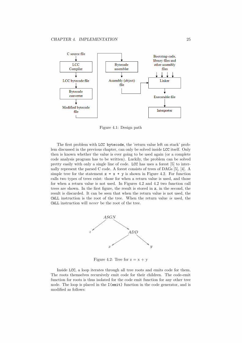
The total design path from C source file(s) to the executable file is shown inFigure 4.1. All C sources are first compiled into LCC bytecode files by the LCCcompiler described in the previous chapter. A small number of minor modifi-cations to the LCC bytecode files are made by the Bytecode converter, andis described in Section 4.3. The assembling (converting the bytecode text intoa binary form), and linking (joining several sources into one executable file)is done in two separate programs; the assembler and the linker. Therefore,the process remains transparent, and a small change in one source file doesn’trequire the entire program to be recompiled/reassembled. The assembler andlinker are described in Sections 4.4 and 4.5.
4.2 The LCC bytecode generator
Unfortunately the LCC bytecode has to be slightly altered to be a good assemblylanguage. To stay compatible with new versions of LCC, the choice has beenmade to make no critical changes to the LCC bytecode so LCC can be updatedwithout breaking the system. Most changes to the LCC bytecode which have tobe made are therefore moved to the next program in the code generation phase,and will be discussed in the next section.
24
CHAPTER 4. IMPLEMENTATION 25
Figure 4.1: Design path
The first problem with LCC bytecode, the ’return value left on stack’ prob-lem discussed in the previous chapter, can only be solved inside LCC itself. Onlythen is known whether the value is ever going to be used again (or a completecode analysis program has to be written). Luckily, the problem can be solvedpretty easily with only a single line of code. LCC has uses a forest [5] to inter-nally represent the parsed C code. A forest consists of trees of DAGs [5], [4]. Asimple tree for the statement z = x + y is shown in Figure 4.2. For functioncalls two types of trees exist: those for when a return value is used, and thosefor when a return value is not used. In Figures 4.2 and 4.2 two function calltrees are shown. In the first figure, the result is stored in z, in the second, theresult is discarded. It can be seen that when the return value is not used, theCALL instruction is the root of the tree. When the return value is used, theCALL instruction will never be the root of the tree.
ASGN
%%KKKKKKKKK
{{wwwwwwwww
z ADD
""EEEE
EEEE
E
yyssssssssss
x y
Figure 4.2: Tree for z = x + y
Inside LCC, a loop iterates through all tree roots and emits code for them.The roots themselves recursively emit code for their children. The code-emitfunction for roots is thus isolated for the code emit function for any other treenode. The loop is placed in the I(emit) function in the code generator, and ismodified as follows:
CHAPTER 4. IMPLEMENTATION 26
ASGN
''NNNNNNNNNNN
{{wwwwwwwww
z CALL
��some func
Figure 4.3: Tree for z = some func()
CALL
��some func
Figure 4.4: Tree for some func()
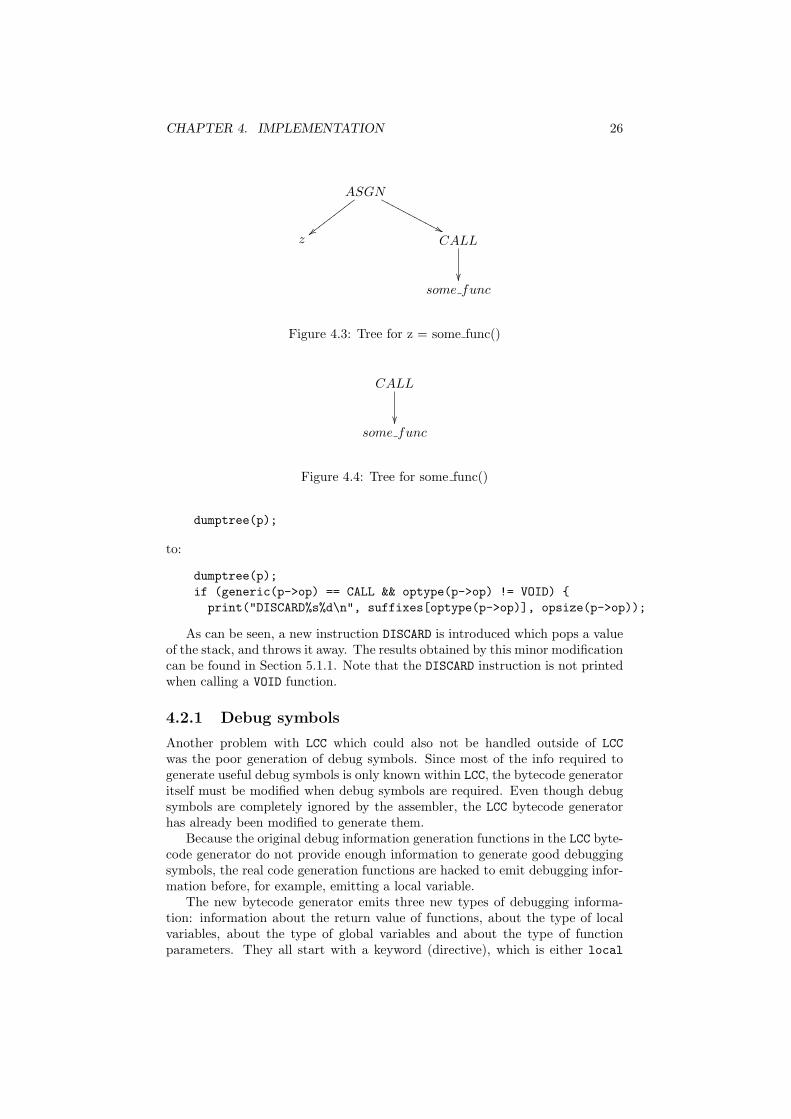
dumptree(p);
to:
dumptree(p);if (generic(p->op) == CALL && optype(p->op) != VOID) {print("DISCARD%s%d\n", suffixes[optype(p->op)], opsize(p->op));
As can be seen, a new instruction DISCARD is introduced which pops a valueof the stack, and throws it away. The results obtained by this minor modificationcan be found in Section 5.1.1. Note that the DISCARD instruction is not printedwhen calling a VOID function.
4.2.1 Debug symbols
Another problem with LCC which could also not be handled outside of LCCwas the poor generation of debug symbols. Since most of the info required togenerate useful debug symbols is only known within LCC, the bytecode generatoritself must be modified when debug symbols are required. Even though debugsymbols are completely ignored by the assembler, the LCC bytecode generatorhas already been modified to generate them.
Because the original debug information generation functions in the LCC byte-code generator do not provide enough information to generate good debuggingsymbols, the real code generation functions are hacked to emit debugging infor-mation before, for example, emitting a local variable.
The new bytecode generator emits three new types of debugging informa-tion: information about the return value of functions, about the type of localvariables, about the type of global variables and about the type of functionparameters. They all start with a keyword (directive), which is either local
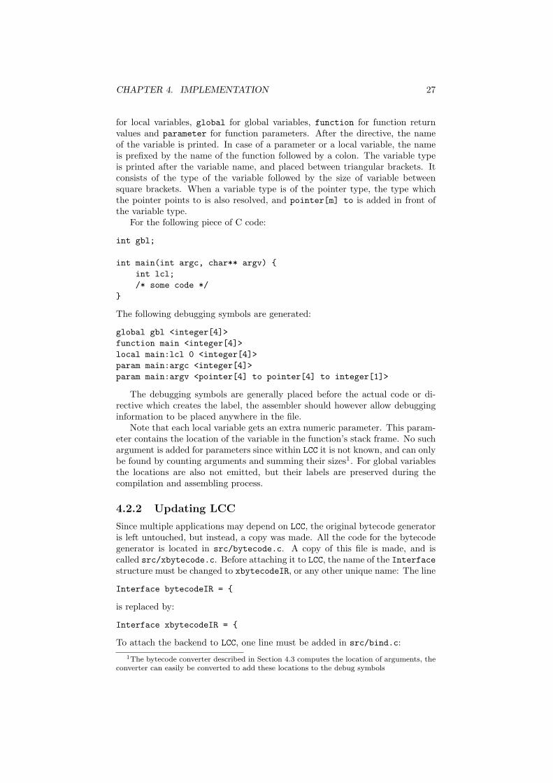
CHAPTER 4. IMPLEMENTATION 27
for local variables, global for global variables, function for function returnvalues and parameter for function parameters. After the directive, the nameof the variable is printed. In case of a parameter or a local variable, the nameis prefixed by the name of the function followed by a colon. The variable typeis printed after the variable name, and placed between triangular brackets. Itconsists of the type of the variable followed by the size of variable betweensquare brackets. When a variable type is of the pointer type, the type whichthe pointer points to is also resolved, and pointer[m] to is added in front ofthe variable type.
For the following piece of C code:
int gbl;
int main(int argc, char** argv) {int lcl;/* some code */
}
The following debugging symbols are generated:
global gbl <integer[4]>function main <integer[4]>local main:lcl 0 <integer[4]>param main:argc <integer[4]>param main:argv <pointer[4] to pointer[4] to integer[1]>
The debugging symbols are generally placed before the actual code or di-rective which creates the label, the assembler should however allow debugginginformation to be placed anywhere in the file.
Note that each local variable gets an extra numeric parameter. This param-eter contains the location of the variable in the function’s stack frame. No suchargument is added for parameters since within LCC it is not known, and can onlybe found by counting arguments and summing their sizes1. For global variablesthe locations are also not emitted, but their labels are preserved during thecompilation and assembling process.
4.2.2 Updating LCC
Since multiple applications may depend on LCC, the original bytecode generatoris left untouched, but instead, a copy was made. All the code for the bytecodegenerator is located in src/bytecode.c. A copy of this file is made, and iscalled src/xbytecode.c. Before attaching it to LCC, the name of the Interfacestructure must be changed to xbytecodeIR, or any other unique name: The line
Interface bytecodeIR = {
is replaced by:
Interface xbytecodeIR = {
To attach the backend to LCC, one line must be added in src/bind.c:1The bytecode converter described in Section 4.3 computes the location of arguments, the
converter can easily be converted to add these locations to the debug symbols

CHAPTER 4. IMPLEMENTATION 28
xx(xbytecode, xbytecodeIR) \
can be placed right under the original
xx(bytecode, bytecodeIR) \
Off course the Makefile must also be altered to compile and link the new sourcefile.
4.3 The bytecode converter
The bytecode converter is a very small and simple program which only mod-ifies a few LCC bytecode directives and instructions. It basically fixes a few“glitches”. All these modifications could have been done by the assembler, butto honor the traditional roll of the assembler, and to keep the process transpar-ent, the modifications are made by a different program. The modifications tothe bytecode the converter makes are listed here:
• Replace procedure directives with real stack frame creation instructions
• Replace the LABEL instruction with a label directive
• The ARG instruction gets a parameter containing the parameter’s offset
• The INDIRB instruction gets a parameter containing the size of the struc-ture
Most of these items are hot fixes for LCC bytecode shortcommings describedin Section 3.3. One new item is the replacement of procedure directives by realinstructions. This is done to simplify the assembling process. The instructionswhich are currently used for stack frame creation are completely based on theworking of the interpreter, and may need to be changed for a real hardwareimplementation. The actual instructions used to create function stack framescan be found in Section 4.6.3.
4.4 The assembler
The assembler is a small program which converts the bytecode into binarycode, and handles all LCC bytecode directives. The conversion is a simpleone-to-one conversion, meaning that theoretically the exact source file can bereproduced when disassembling the binary assembly file, only debug informationand comment will be lost. Except for the code segment, the binary coding of thesegments is exactly done as described by the assembler directives described inSection 3.1. The binary coding of the code segment, as well as the format of theassembly file can be found in Appendix D.2. All labels are left intact within theassembler, thus all addresses must be computed within the linker. All addresseswithin the binary code are replaced by unique identifiers, which correspond toentries in a table containing all labels. For example: when calling functionadd, the parameter of the ADDRG instruction (which is used to get the addressof add), is replaced by an unique identifier which corresponds to a table entrycontaining the actual address and segment of add. To find all unique identifiers
CHAPTER 4. IMPLEMENTATION 29
in the binary code, a bitmap pattern is generated. Each bit represents one byte,and each bit being one represents that byte being part of an unique identifier(and thus should be replaced by the actual address. The linker should thus scanthe bitmap for an unique identifier, read it, find the address and segment withinthe table, and update the code with the final (absolute) address. An exampleof the assembling process can be found in Appendix F. Debug information iscurrently discarded within the assembler. All directives introduced in Section4.2 are accepted as valid input, but nothing is done with them yet.
4.5 The linker
The linker joins all object files into one executable file. In addition it alsocomputes all label locations and updates the segments with these locations. Ingeneral the linker walks through the following steps:
• Load all files into memory, store them in Assembly structures
• Check all labels, and connect labels pointing to code in other assemblies
• Compute the combined size of the four segments (see Section 3.1.1)
• Compute all label locations
• Update the binary segment data
• Write all to segments to a single file
In addition to the assemblies given as input files, the linker may add severalother assemblies if required. These are discussed in the following sections.
Upon execution, the entire executable should be copied to the CPU’s mem-ory. The program assumes it is placed on address 0, if not, the address of eachmemory operation must be incremented by the programs base address. TheCODE segment is the first segment in the executable, directly followed by theLIT segment and the DATA segment. The BSS segment is again not written tothe final executable, since it would only contain junk. Instead, a dummy la-bel with the name $endprog is introduced in the linker who points to the firstbyte beyond the BSS segment. The location of this label can be used to correctlyplace the stack or heap within the processing unit’s memory. Note that the labelstarts with a dollar sign, meaning the label is only accessible through bytecode,and will never interfere with any existing C variables or functions. The stackcan be placed anywhere in memory, but needs to grow upwards in memory (seeSection 4.6.2). The stack can therefore be placed right after the program, whileall dynamically allocated data objects can be placed at the end of the memory.
4.5.1 Bootstrap code
The bootstrap code is a small piece of code placed at the very beginning of theexecutable file. The bootstrap code is merely a bridge between the startup of theprocessing unit, which will start executing at address 0, and the startup of the Ccode, which will start at the call to the main function. A simple bootstrappingcode can thus exist of only a few lines of code calling main.

CHAPTER 4. IMPLEMENTATION 30
The standard bootstrap code which is used for this project contains in addi-tion the setup of the two standard parameters to the main function: argc andargv. They will not contain any useful information, but they will be valid forany C program using them.
The bootstrap code also contains code to allocate the BSS segment. Sincethe stack grows upwards (see Section 4.6.2) on default, it is placed in memoryright after the executable file, which is placed at address zero. To save space,the BSS segment is never included in the executable file, and the stack, whenstarted directly after the program’s data, will overlap the BSS segment. Thebootstrap code starts by moving the stack beyond the BSS segment. To dothis, some variables must be placed on the stack which thus overwrites the BSSsegment. This is not a problem, since uninitialized variables contain junk whenthe program starts anyway. To move the stack a new instruction NEWSTACK isintroduced, which moves the stack to the location pointed by the value on topof the stack. Any values left on the stack before using NEWSTACK are no longervalid after a NEWSTACK instruction.
4.5.2 Library files
Some functions may be so widely used they need to be put in library files. MostC compilers provide the programmer with a standard library containing a lotof functions for I/O, mathematical calculations, etcetera. Library files can becreated and linked (see Appendix E.4) by the linker. A library file consists ofseveral assembly files, which are added to the executable when required. If onelibrary assembly needs another library assembly it is also automatically linked,however an assembly within a library is always added completely to the exe-cutable. When the functions printf and putchar, for example, are placed ina library in the same assembly, printf is always added to the executable whenputchar is. However, when they are put in the same library, but in differ-ent assemblies, the use of printf automatically imports printf and putchar(assuming printf uses putchar), but the use of putchar won’t import printf.
4.6 The interpreter
The interpreter is a program which interprets and executes binary instructionsgenerated by the assembler. The engine of the interpreter, the part which ac-tually executes the instructions, is separated from the user interface. This isdone so the interpreter can also be embedded in other applications for test-ing or debugging purposes. How to embed the interpreter is described inAppendix B. The layout of the interpreter is shown in Figure 4.6. The in-terpreter is started from interpreter.c which continuously calls execute ininterpreter_engine.c, which executes one instruction. I/O required by pro-grams running on the interpreter is handled by the operation system specificio.c. The execute function relies on several sub functions which handle, forexample, comparison, arithmetic and memory operations. These operations areall mapped on the native operations supported by C, the OS or the runningprocessor.
The first section of this paragraph describes the interpreter engine, howprograms are loaded and executed. The second section describes the stack,

CHAPTER 4. IMPLEMENTATION 31
how it is built and maintained. Finally, Section 4.6.3, describes the few newinstructions the interpreter supports.
Figure 4.5: Interpreter
4.6.1 The interpreter engine
The engine of the interpreter is the part of the interpreter which loads pro-grams into its memory, and executes the instructions. It also has several helperfunctions to convert variables as they appear in the interpreter memory to Cvariables, which can be used by programs embedding the interpreter for maxi-mum control.
The interpreter engine uses an Interpreter information structure whichholds the state of the interpreter, and a pointer to its memory. Thecreate_interpreter is used to create a new interpreter information structure.The desired size of interpreter memory is passed to this function, and can notbe changed afterwards. Loading an executable into the interpreter’s memoryis done by the load_program function, which accepts a file pointer. The fileis loaded into the lower part of the memory (address 0-...), and thus all pre-computed pointers in the program are also valid for the interpreters memory.However, this makes it impossible to load multiple programs on the interpreter.
The interpreter always starts executing at address 0, which should holdsome bootstrap code which calls the main function. See Section 4.5.1 for moreinformation about the used bootstrap code. The execute function executesthe instruction pointed to by the program counter: PC. The execute functionreturns an error code (defined in src/interpreter_engine.h) if the instruc-tion could for some reason not be executed, ERR_EXIT_PROGRAM when the HALTinstruction is encountered or ERR_NOERROR when the instruction was executedsuccessfully.

CHAPTER 4. IMPLEMENTATION 32
4.6.2 Stack frames
LCC makes a few assumptions about the stack frame when generating LCC bytecode,and to be able to correctly execute LCC bytecode, the stack frame must be de-signed by these assumptions. The assumptions are listed here, some are alreadydiscussed in previous paragraphs, and some others are new.
• Space for local function variables is allocated when entering a function.
• Space for function arguments for callees is allocated when entering thecaller function.
• The first value in a structure is assumed to have the lowest absolute mem-ory address of all values in a structure (see Section 3.2.7).
• Because of the previous assumption, the first of all local variables, and thefirst of all arguments, must also have the lowest absolute memory address.
• A function return instruction should rollback the stack to the point rightbefore the call, with just the return value added: from the caller’s pointof view, a CALL instruction acts just like a CNST instruction.
The stack frame is further optimized, to require as small possible amount ofpointers as possible. The first pointer which is required for any stack is apointer pointing to the top of the stack. This pointer is from now on calledthe stack pointer, or SP. The design is started by assuming some values alreadyexist on the stack, and a function call is encountered. The CALL function mustwrite the return address to the stack, since after the call, the return address isno longer known. Right after a function call, the stack frame thus looks likeFigure 4.6.2.
. . .Caller function
. . .
. . .Return address
←SP
Figure 4.6: Stack frame step I
Note that the stack frame here grows downwards, this can either be to ahigher or a lower memory address. Next, space for both the arguments to sub-functions and space for the function’s local variables must be allocated. Tobe able to access these areas, pointers must be set to the lowest address ofthese spaces. These pointers are called the local pointer (LP) and the argumentpointer (AP). An additional pointer is needed which denotes the beginning of afunction’s stack frame. This pointer is called the frame pointer, or FP. Since itis not yet known whether the stack frame should grow up in memory, or downin memory, in the following pictures some pointers appear twice, once with anup pointing arrow, to denote this pointer is required when the stack grows upin memory, or with a down pointing arrow, which is required when the stackgrows down. This is shown in Figure 4.6.2

CHAPTER 4. IMPLEMENTATION 33
Note that placing the argument block above the local block is a randomchoice, and they can be exchanged when needed.
Since the pointers must be able to be restored on function return, they mustalso be placed on the stack. These should be stored before the argument andlocal blocks, because the creation of these blocks also generate the new pointers,as shown in Figure 4.6.2
The pointers are saved in the processing unit state block. The state blockis accessible through the FP pointer, and thus no new pointer is required. Sincethe state block has a fixed size, the location of FP can be reached from AP whenthe stack grows upward in memory. Therefore, one of those registers can beleft out when letting the stack grow upwards in memory. The result is show inFigure 4.6.2.
. . .Caller function
. . .
. . .Return addressArgument block
Local block.
←FP/AP↓←AP↑/LP↓←LP↑
Figure 4.7: Stack frame step II
. . .Caller function
. . .
. . .Return address
StateArgument block
Local block. . .
←FP←AP↑←AP↓/LP↑←LP↓
Figure 4.8: Stack frame step III
. . .Caller function
. . .
. . .Return address
StateArgument block
Local block. . .
←Low address
←FP←LP←High address
Figure 4.9: Stack frame step IV
CHAPTER 4. IMPLEMENTATION 34
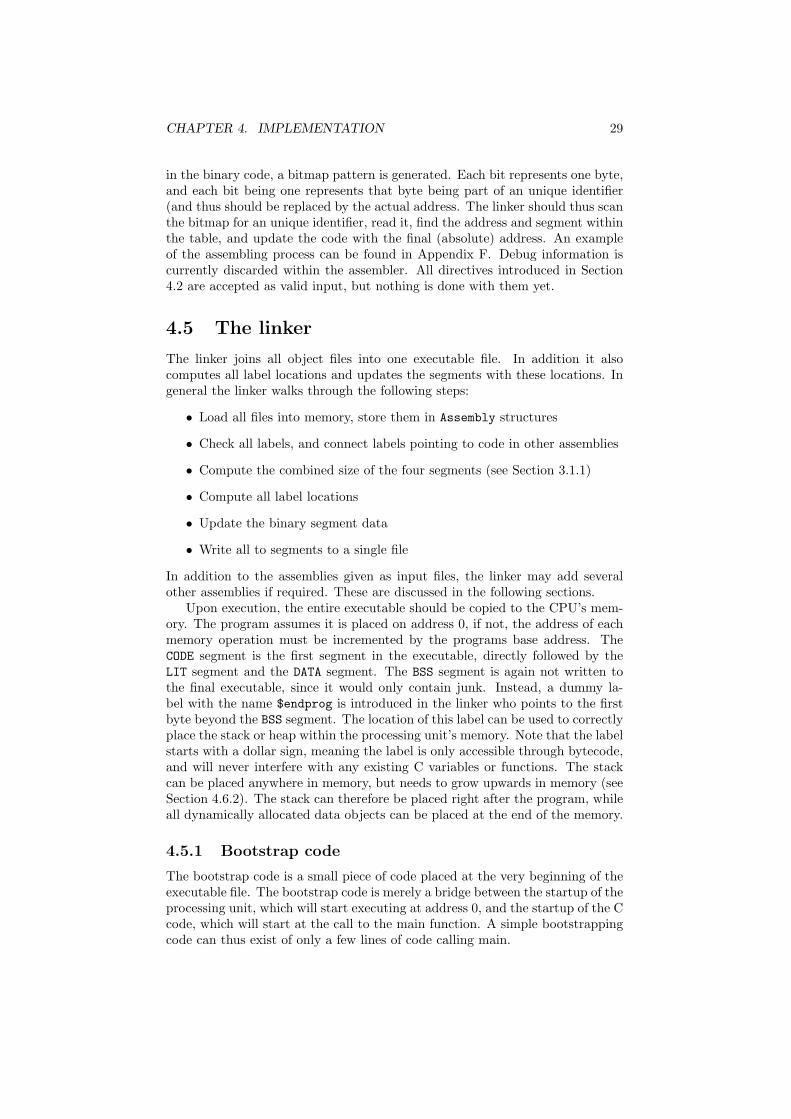
The argument pointer is reintroduced by letting it point to the argumentblock of the previous function. This location is required to be able to load thearguments passed to the current function. The final stack frame is shown inFigure 4.6.2. All stack frames for the example introduced in Section 3.1.2, areshown in Section 4.7.
. . .Argument blockCaller function
. . .
. . .Return address
StateArgument block
Local block. . .
←AP
←FP←LP
Figure 4.10: Final stack frame layout
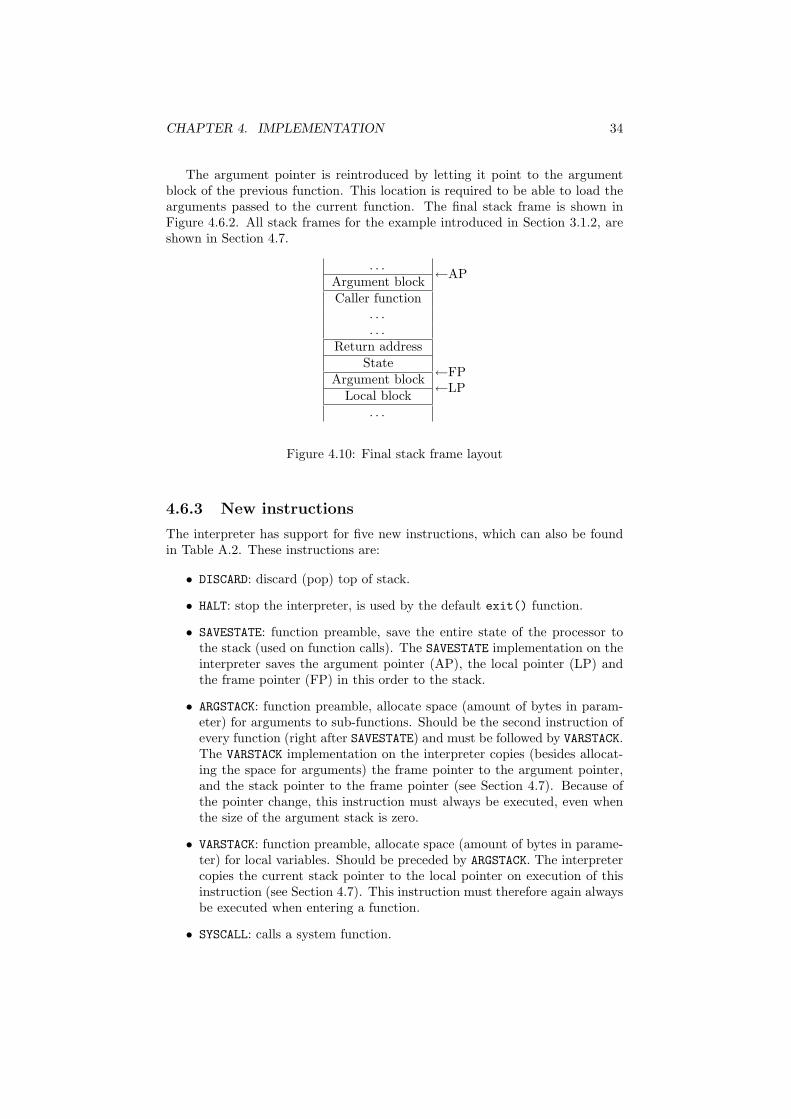
4.6.3 New instructions
The interpreter has support for five new instructions, which can also be foundin Table A.2. These instructions are:
• DISCARD: discard (pop) top of stack.
• HALT: stop the interpreter, is used by the default exit() function.
• SAVESTATE: function preamble, save the entire state of the processor tothe stack (used on function calls). The SAVESTATE implementation on theinterpreter saves the argument pointer (AP), the local pointer (LP) andthe frame pointer (FP) in this order to the stack.
• ARGSTACK: function preamble, allocate space (amount of bytes in param-eter) for arguments to sub-functions. Should be the second instruction ofevery function (right after SAVESTATE) and must be followed by VARSTACK.The VARSTACK implementation on the interpreter copies (besides allocat-ing the space for arguments) the frame pointer to the argument pointer,and the stack pointer to the frame pointer (see Section 4.7). Because ofthe pointer change, this instruction must always be executed, even whenthe size of the argument stack is zero.
• VARSTACK: function preamble, allocate space (amount of bytes in parame-ter) for local variables. Should be preceded by ARGSTACK. The interpretercopies the current stack pointer to the local pointer on execution of thisinstruction (see Section 4.7). This instruction must therefore again alwaysbe executed when entering a function.
• SYSCALL: calls a system function.

CHAPTER 4. IMPLEMENTATION 35
An example of the usage of the SAVESTATE, ARGSTACK and VARSTACK instruc-tions can be found in Section 4.7.
The SYSCALL instruction is introduced to interface with the environment,for example to read and write characters from and to the console, or read someinterpreter properties. The SYSCALL instruction takes one or two parametersfrom the stack, and always places one parameter back. The top of the stackshould be a constant 32-bit integer denoting the type of system call to be made.All parameters and return values of the SYSCALL instruction are 32 bit integers.The following types are supported:
• 0x01 read and return one character from the console (blocking).
• 0x02 write one character to the console, returns character written (takesone extra 32 bit integer value from the stack).
• 0x03 read and return one character from the console (non-blocking). Re-turns -1 when no character is present.
• 0x04 generate and return a random number.
• 0x05 return the number of instructions executed.
The interpreter has a special I/O library rather than using standard C func-tions directly. The main reason for this is the support for non-blocking reads.The standard getchar function provided by the C library does not return untila character is written. This is very nice on a multitasking environment, butwhen simulating an embedded application this is highly non-desirable.
The I/O library, stored in src/IO.c, supports three functions to access theconsole: read_char, which reads one character, and blocks when no characteris available, read_char_non_blocking, which reads one character, or returns-1 when no character is available, and write_char, which writes one characterto the console. In addition, the functions init_io and term_io are also calledat the startup and exit of the interpreter. Since non blocking reads are notsupported by C itself, this is done by directly manipulating the operation system.The I/O library currently supports Windows and Linux, and chooses it’s OS atcompile-time by checking if the _WIN32 macro is defined.
4.7 Program stack frame example
This section contains the stack frames which will be generated by the interpreterwhen running the code sum = add(a, b);. The first stack frame, shown inFigure 4.7, is taken right before the function call to add. On the top of thestack, the address of add can be found which is needed by the CALL instruction(see Section 3.2.3. Before that, the address of the sum variable can be found,which is required to assign the result of add to sum (see Section 3.2.2).
Next, the CALL instruction is executed. The address of add is taken fromthe stack, and the return address (next instruction in caller function) is placedon the stack (see Section 3.2.3). The stack frame taken right after the CALLinstruction is shown in Figure 4.7.
The program counter is now pointing to the first instruction of add, whichshould be a SAVESTATE instruction. This instruction saves the AP, LP and FPpointers to the top of the stack, as shown in Figure 4.7.
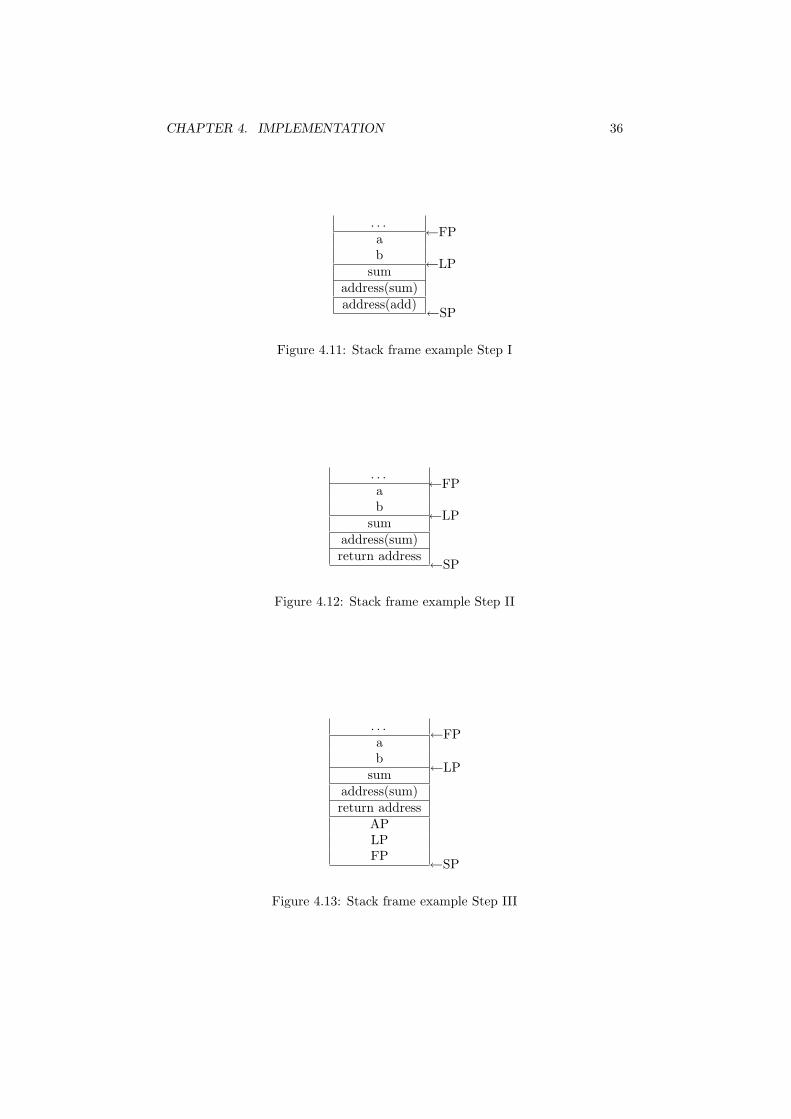
CHAPTER 4. IMPLEMENTATION 36
. . .ab
sumaddress(sum)address(add)
←FP
←LP
←SP
Figure 4.11: Stack frame example Step I
. . .ab
sumaddress(sum)return address
←FP
←LP
←SP
Figure 4.12: Stack frame example Step II
. . .ab
sumaddress(sum)return address
APLPFP
←FP
←LP
←SP
Figure 4.13: Stack frame example Step III

CHAPTER 4. IMPLEMENTATION 37
Now that the processor state is saved, a new stack frame must be createdusing the ARGSTACK and VARSTACK instructions. The two stack frames takenafter each of these instructions are shown in figures 4.7 and 4.7. Note that adddoes not call any other functions, or use any local variables. The parameters ofboth ARGSTACK and VARSTACK are therefore zero, and no space is allocated forlocal variables and arguments to callee functions.
. . .ab
sumaddress(sum)return address
APLPFP
←AP
←LP
←SP/FP
Figure 4.14: Stack frame example Step IV
. . .ab
sumaddress(sum)return address
APLPFP
←AP
←SP/FP/LP
Figure 4.15: Stack frame example Step V
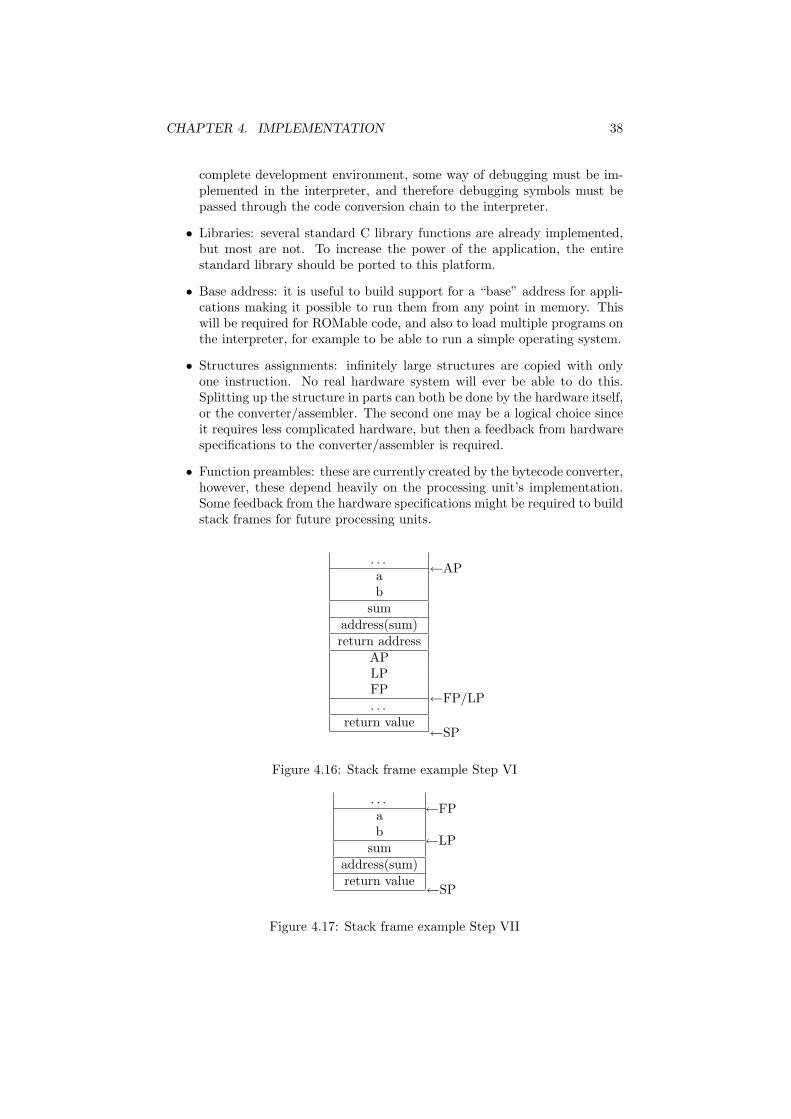
The next stack frame, shown in Figure 4.7, is taken just before the RETinstruction. The return value is placed on top of the stack.
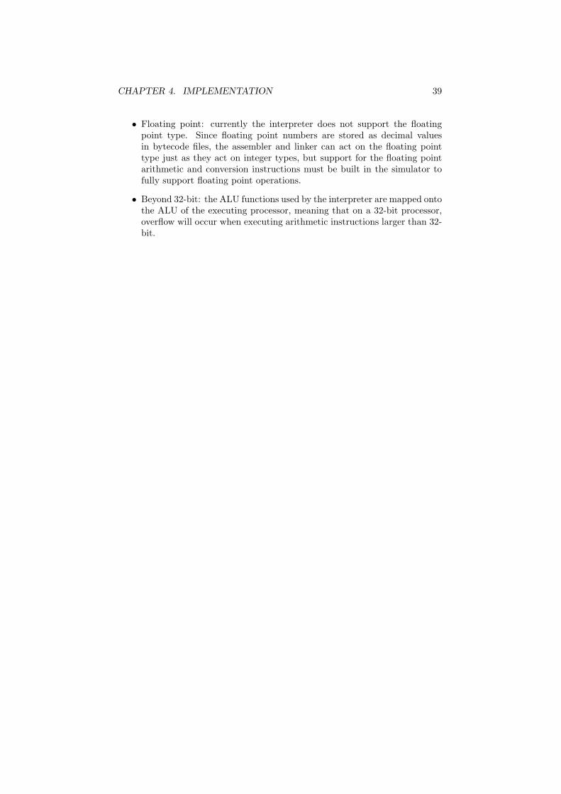
The final stack frame is shown in Figure 4.7, and is taken right after thereturn from add. All pointers are restored to there original values from beforethe function call, and the return value is the only result left from the call toadd.
4.8 Future work
Although many plain C programs can be compiled and executed on the inter-preter, some issues are still open for future work. A few of these issues are givenin the following list, with a brief description on how this can be accomplished.
• Debugging: debugging is not supported by the interpreter, and debugsymbols are discarded by the assembler. To turn the application in a
CHAPTER 4. IMPLEMENTATION 38
complete development environment, some way of debugging must be im-plemented in the interpreter, and therefore debugging symbols must bepassed through the code conversion chain to the interpreter.
• Libraries: several standard C library functions are already implemented,but most are not. To increase the power of the application, the entirestandard library should be ported to this platform.
• Base address: it is useful to build support for a “base” address for appli-cations making it possible to run them from any point in memory. Thiswill be required for ROMable code, and also to load multiple programs onthe interpreter, for example to be able to run a simple operating system.
• Structures assignments: infinitely large structures are copied with onlyone instruction. No real hardware system will ever be able to do this.Splitting up the structure in parts can both be done by the hardware itself,or the converter/assembler. The second one may be a logical choice sinceit requires less complicated hardware, but then a feedback from hardwarespecifications to the converter/assembler is required.
• Function preambles: these are currently created by the bytecode converter,however, these depend heavily on the processing unit’s implementation.Some feedback from the hardware specifications might be required to buildstack frames for future processing units.
. . .ab
sumaddress(sum)return address
APLPFP. . .
return value
←AP
←FP/LP
←SP
Figure 4.16: Stack frame example Step VI
. . .ab
sumaddress(sum)return value
←FP
←LP
←SP
Figure 4.17: Stack frame example Step VII
CHAPTER 4. IMPLEMENTATION 39
• Floating point: currently the interpreter does not support the floatingpoint type. Since floating point numbers are stored as decimal valuesin bytecode files, the assembler and linker can act on the floating pointtype just as they act on integer types, but support for the floating pointarithmetic and conversion instructions must be built in the simulator tofully support floating point operations.
• Beyond 32-bit: the ALU functions used by the interpreter are mapped ontothe ALU of the executing processor, meaning that on a 32-bit processor,overflow will occur when executing arithmetic instructions larger than 32-bit.

Chapter 5
Test results
This chapter contains the test results obtained by analyzing compiled programs,executing them and comparing them to programs compiled for other processingunits. In addition, the instruction set and register usage for de LCC Bytecodeinterpreter is compared to those of a few existing processing units. The firstsection of this chapter shows some analysis of the LCC Bytecode language. Inthe second section, the assembly files of programs compiled for different pro-cessing units are compared, and in the last section, different processing unitsare compared to the LCC Bytecode interpreter written for this research.
The test programs which are used to generate these results are a simplegame zeeslag and a fast Fourier algorithm fft written by the author, a memorymonitor application written by Arjan van Gemund, mymon, and the test programwhich comes with the softfloat library, float, written by John R. Hauser.
5.1 LCC Bytecode analysis
In this section, LCC Bytecode is further analyzed. In the following sections, theresults for the stack-leak fix are shown, and an overview of the occurrence of allinstruction types is given.
5.1.1 Results of the DISCARD instruction
As mentioned in section 3.3.5, unused return values stay on the stack forever.To fix this problem, a new instruction was introduced: the DISCARD instruction,which discards the top n bytes of the stack. This method slightly increasesthe amount of instructions to be executed, and thus decreases the speed of theapplication, but it fixes a memory leak. It should therefore be considered a nec-essary fix, rather than an optimization. Using the -nd command line parameteron the interpreter, the DISCARD instruction can be ignored (the interpreter willnot execute the instruction, nor will it increase the instructions executed count).Several test files which can be found in the projects test directory where exe-cuted with and without the use of the DISCARD instruction, the results can befound in Table 5.1.
The test files used for these results can all be found in the test directory inthe projects directory. The retvaltest is a test program written to show the
40
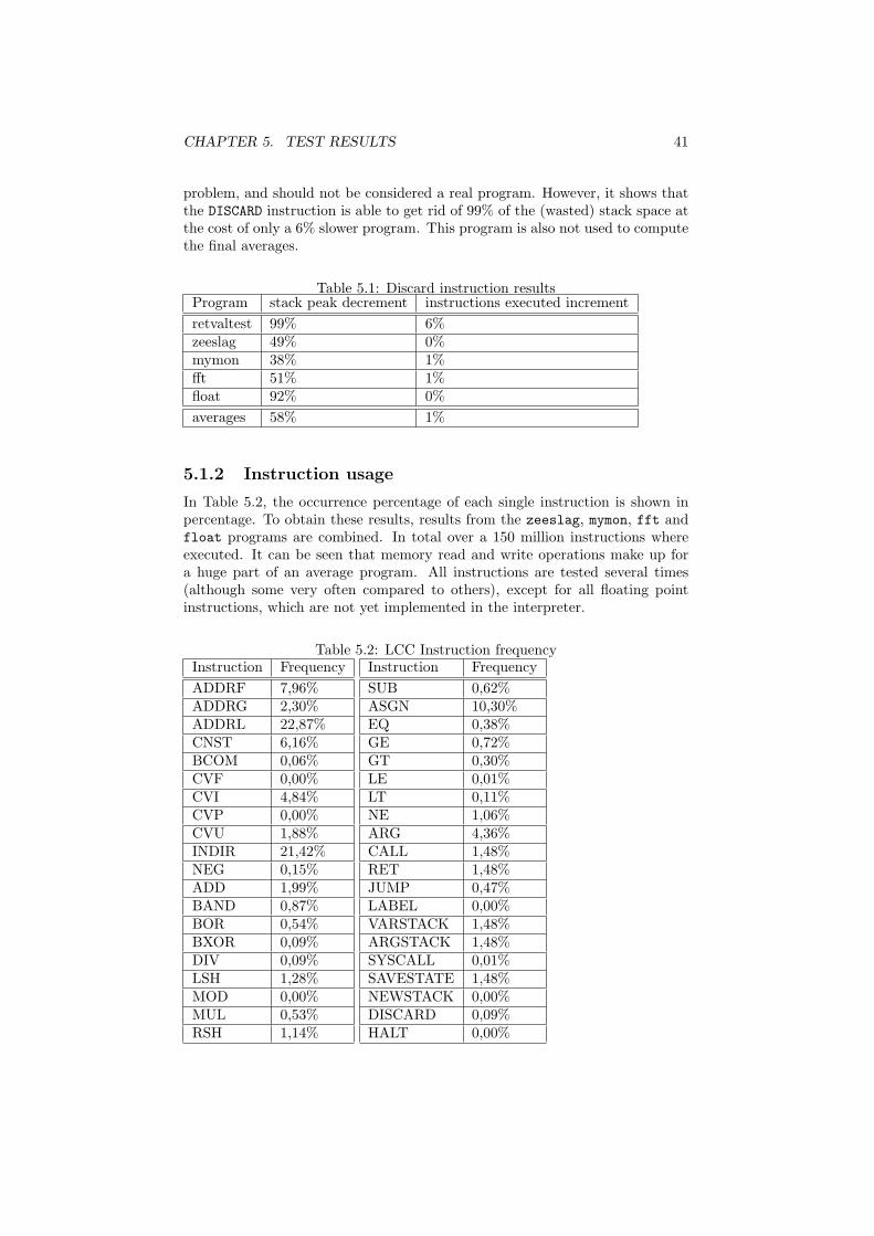
CHAPTER 5. TEST RESULTS 41
problem, and should not be considered a real program. However, it shows thatthe DISCARD instruction is able to get rid of 99% of the (wasted) stack space atthe cost of only a 6% slower program. This program is also not used to computethe final averages.
Table 5.1: Discard instruction resultsProgram stack peak decrement instructions executed incrementretvaltest 99% 6%zeeslag 49% 0%mymon 38% 1%fft 51% 1%float 92% 0%averages 58% 1%
5.1.2 Instruction usage
In Table 5.2, the occurrence percentage of each single instruction is shown inpercentage. To obtain these results, results from the zeeslag, mymon, fft andfloat programs are combined. In total over a 150 million instructions whereexecuted. It can be seen that memory read and write operations make up fora huge part of an average program. All instructions are tested several times(although some very often compared to others), except for all floating pointinstructions, which are not yet implemented in the interpreter.
Table 5.2: LCC Instruction frequencyInstruction FrequencyADDRF 7,96%ADDRG 2,30%ADDRL 22,87%CNST 6,16%BCOM 0,06%CVF 0,00%CVI 4,84%CVP 0,00%CVU 1,88%INDIR 21,42%NEG 0,15%ADD 1,99%BAND 0,87%BOR 0,54%BXOR 0,09%DIV 0,09%LSH 1,28%MOD 0,00%MUL 0,53%RSH 1,14%
Instruction FrequencySUB 0,62%ASGN 10,30%EQ 0,38%GE 0,72%GT 0,30%LE 0,01%LT 0,11%NE 1,06%ARG 4,36%CALL 1,48%RET 1,48%JUMP 0,47%LABEL 0,00%VARSTACK 1,48%ARGSTACK 1,48%SYSCALL 0,01%SAVESTATE 1,48%NEWSTACK 0,00%DISCARD 0,09%HALT 0,00%

CHAPTER 5. TEST RESULTS 42
5.2 Assembly files
In this section, the assembly (text) files are compared for several processingunits. LCC is used to generate i386 code, MIPS code and LCC Bytecode. SDCCto generate code for the 8051. In table 5.3 the number of assembly lines forseveral programs are displayed.
Table 5.3: Assembly file lines comparisonProgram i386 MIPS 8051 LCC Bytecodezeeslag 1320 (63%) 1258 (60%) 2042 (98%) 2088 (100%)mymon 3642 (74%) 3259 (66%) 3795 (77%) 4954 (100%)fft 450 (67%) 424 (63%) ? 670 (100%)float 3390 (68%) 3236 (65%) ? 4972 (100%)average (perc.) 68% 64% ? 100%
At first glance, the number of lines in an assembly file may give any infor-mation, but when the following things are considered, they do:
• Each line in an assembly file contains one instruction
• Assembler directives can be neglected
• If a program is compiled for platform A and B, and assembly file A containsn times as much instructions as assembly file B, the number of instructionsexecuted on platform A will also be roughly n times as much as the numberof instructions executed on platform B, when the extra instructions areuniformly distributed through the code.
It can be seen both MIPS and i386 assembly code files are about 2/3 the sizeof the LCC Bytecode files. The main reason for this is the fact that both theMIPS and the i386 support reading and writing from and to a memory locationrelative to a register with only one instruction, where LCC Bytecode needs atleast two. As can be seen in Table 5.2, these instructions make up for a verylarge part of any program. Unfortunately, SDCC was not able to compile thefloat and fft programs, thus no test results are available. This method ischosen over looking at the sizes of the object or executable files, since both cancontain a huge amount of information besides the actual code, and are verydepended on the size (8-bit 8051, 32-bit i386) of the processor.
5.3 Processing unit comparison
Finally, in this section, several processing units are compared to the writtenLCC Bytecode interpreter.
It can be seen a lot can be won on the complexity of the processing unitwhen designing it from the viewpoint of C. Both MIPS and i386 are very pow-erful processor which have come a long way, but clearly support a lot moreinstructions than necessary to execute just C code, which will definitely makethose processors a lot more complicated. One should remember however thatthe i386 and MIPS where designed to be much more than just a C processor. To

CHAPTER 5. TEST RESULTS 43
be able to build operating systems like Linux in LCC Bytecode, the instructionset must be slightly expanded to support threading and interrupts.
Table 5.4: Instruction count and sizeProcessing unit Supported Instruction size General purpose Control
instructions (bits) registers registersMIPS R2000[8] 60+ 32 28 48051[1] 43 8-24 81 2i386[9] 100+ ? 4 4LCC bytecode 38 16-48 0 3interpreter

Chapter 6
Conclusions
In Chapter 2, it is shown that LCC Bytecode is the best choice for an assemblylanguage, when building a processor based on C in limited time. Althoughseveral modifications had to be made to efficiently execute the code generatedby the LCC compiler, test results show that, if not all, most standard C programscan correctly be converted to LCC Bytecode and executed.
A software interpreter was written to execute the generated LCC Bytecodeprograms, and was used to analyze the code generated by LCC. To fully supportthe LCC Bytecode language, 31 instructions needed to be implemented, plusseven new instructions for stack frame manipulation and interpreter control.The total number of 38 required instructions is much lesser than the numberof instructions supported instructions by most existing processors. Basing anew processor on LCC Bytecode will thus result in a much simpler processor,which will in the end result in a smaller, more reliable processor which can bedeveloped in lesser time.
Even though no real speed tests where done, it can be seen from the gener-ated assembly files that the average number of instructions per C application ishigher when using LCC Bytecode than most other assembly languages. Thus aLCC Bytecode processor with the same amount of instructions per second as,for example, a MIPS processor, will be slightly slower. This is mostly caused bythe fact that most assembly languages allow memory access in one instruction,while LCC Bytecode requires two. Since these instructions make up for aboutone third of an average C program, a lot of instructions are lost here. In termsof instructions per second, the new processor will most likely be a lot slowerthan most modern processors, which are all mostly developed to be fast, notsmall or simple.
In conclusion, it is seen from the previous chapters that basing a new pro-cessor completely on the C programming language will result in a less complexprocessor, which makes the development easier and thus faster. In the end thiswill require smaller (and thus cheaper) chips. When lowering development andproduct costs have a higher priority than using the fastest processor available,designing a processor based on C might therefore be a better solution thandesigning a processor based on hardware properties.
44

Appendix A
LCC bytecode instructions
In Table A.2, quoted from The lcc 4.x Code-Generation Interface [6], showall possible instructions generated by the LCC Bytecode generator. The firstcolumn denotes the opcode as it appears in LCC Bytecode files. The secondand third column contain the possible type and sizes for this opcode. The sizecolumn contains blocks of sizes, each block shows the possible sizes for onetype. If an instruction supports two types, two blocks will be found in the sizecolumn. Since the structure and void types have no size, they will also have nocorresponding allowed size block in the third column. The types and sizes aredenoted as letters which are defined in Table A.1. Finally, the last column givesa brief description of the instruction.
The last few entries in the instruction table are not generated by LCC, butare added to successfully execute standalone programs.
Table A.1: LCC Instruction type and size suffixes
Type suffix Meaning (C)F Floating pointI Signed integerU Unsigned integerP PointerV VoidB Structure
Size (bytecode) Size (C)f sizeof(float)d sizeof(double)x sizeof(long double)c sizeof(char)s sizeof(short)i sizeof(int)l sizeof(long)h sizeof(long long)p sizeof(void*)
45

APPENDIX A. LCC BYTECODE INSTRUCTIONS 46
Table A.2: LCC InstructionsOperator Type Suffixes Sizes OperationADDRF ...P.. p address of a parameterADDRG ...P.. p address of a globalADDRL ...P.. p address of a localCNST FIUP.. fdx csilh csilh p constantBCOM .IU... ilh ilh bitwise complementCVF FI.... fdx ilh convert from floatCVI FIU... fdx csilh csilhp convert from signed integerCVP ..U... p convert from pointerCVU .IUP.. csilh csilh p convert from unsigned integerINDIR FIUP.B fdx csilh csilh p fetchNEG FI.... fdx ilh negationADD FIUP.. fdx ilh ilhp p additionBAND .IU... ilh ilh bitwise ANDBOR .IU... ilh ilh bitwise inclusive ORBXOR .IU... ilh ilh bitwise exclusive ORDIV FIU... fdx ilh ilh divisionLSH .IU... ilh ilh left shiftMOD .IU... ilh ilh modulusMUL FIU... fdx ilh ilh multiplicationRSH .IU... ilh ilh right shiftSUB FIU... fdx ilh ilhp p subtractionASGN FIUP.B fdx csilh csilh p assignmentEQ FIU... fdx ilh ilhp jump if equalGE FIU... fdx ilh ilhp jump if greater than or equalGT FIU... fdx ilh ilhp jump if greater thanLE FIU... fdx ilh ilhp jump if less than or equalLT FIU... fdx ilh ilhp jump if less thanNE FIU... fdx ilh ilhp jump if not equalARG FIUP.B fdx ilh ilh p argumentCALL FIUPVB fdx ilh ilh p function callRET FIUPVB fdx ilh ilh p function returnJUMP ....V. unconditional jumpLABEL ....V. label definitionHALT ....V. Stop interpreterARGSTACK ....V. Create argument stackVARSTACK ....V. Create local variable stackSYSCALL FIUP.. fdx ilh ilh p Call special functionSAVESTATE ....V. Saves processor state on stackNEWSTACK ....V. Creates a new stackDISCARD FIUP.. fdx ilh ilh p Discard top of stack

Appendix B
Embedding the interpreter
The interpreter is fully embedable, meaning it can be linked with any applicationwhich can then run code on the interpreter. This feature makes it possible totest only parts of a program on the interpreter, while running the running therest of the code natively. The source code used in this chapter can be found inthe test/embed directory of the project.
The first section of this chapter describes how to embed the interpreter in anapplication: how to link the interpreter with the application and how to start it.The second paragraph describes how to call a function in the embedded code.
B.1 Embedding the interpreter
To embed the interpreter in an existing C program, the headerinterpreter_engine.h which is placed in the projects source directory, mustbe included. From then, several functions are available to control the interpreter.
The first step is to create a new instance of the interpreter, which must bedone by calling create_interpreter. This function returns a pointer to aninterpreter information structure (Interpreter*), or NULL if something wentwrong. It takes one argument: the total amount of memory the interpreter canaccess. This can not be altered later, and must be large enough to hold theprogram’s executable, the uninitialized variables and the programs stack. Theinterpreter will generate an error when it runs out of memory, so when it runsout, increase the memory size and try again.
When the interpreter is created succesfully, an executable file must be loaded.This is done with the load_program function, which takes two arguments: aFILE* to the executable and an Interpreter* to the interpreter info structurecreated by the previous function. This function will return zero when it failes(not enough memory or file access violation). From this moment, the interpreteris ready to execute instructions.
The execute function executes one instruction and sets the program counterto the next. It returns an error code (see interpreter engine.h for all codes) whenan error occures, or ERR_NOERROR when it succeeds. A very simple interpreter(without any error checks) would look like the following:
Interpreter* interpreter;interpreter = create_interpreter(1024*1024);
47

APPENDIX B. EMBEDDING THE INTERPRETER 48
load_program(executable_file, interpreter);while(execute(interpreter) == ERR_NOERROR);
To compile your program, three files must be linked with it: interpreter_engine.o,io.o and instructions.o. The first file contains the actual interpreter, thesecond some extended io functions1 and the third the instruction decoder.
B.2 Calling a function
The previous example shows how to run a complete program on the interpreter.More usefull is the possibility to run only a part of the program on the inter-preter. When embedding the interpreter it is possible to run only one specificfunction. Several actions must be performed to call a function on the interpreter.These are all described in the following sections.
B.2.1 Gathering information
Since neither the debugger, nor the linker, nor the interpreter supports debug-ging symbols (yet), it is up to the programmer to pass all relevant informationabout the function to the interpreter and to make sure this information is cor-rect. At first the complete function declaration must be known: the type andcount of the parameter as well as the type of the return value must be passedcorrectly to the interpreter. This can off course be directly extracted from therunning C source file. Finally also the function’s location in the executable mustbe provided. All final addresses are computed during the linking stage of thebuild, and only after this stage, the addresses are valid. Luckily, the linker canwrite the addresses of all public variables and functions2 to the screen whilelinking the program. This is done by supplying the linker with the -v commandline switch. For example:
linker -v func_serv.co -lib stdio.cl -o testcode.ce
Public functions:Name: Location:exit 0x0000003Amult 0x00000100main 0x00000080set_i 0x000001EAadd 0x000000B0sub 0x000000D8pow 0x00000150div 0x00000128
Variables:Name: Location:i 0x000002F0
1one may wants to make his/her own io.o when embedding which does not use stdin andstdout directly.
2private/local functions and variables are not shown.
APPENDIX B. EMBEDDING THE INTERPRETER 49
Here the addresses of all public functions in the original func serv.c are printed,as well as the single public variable declared in func_serv.h.
B.2.2 Preparing the call
Before making a function call, the stack must be prepared for it. All parametersmust be placed on the stack and the stack pointers must be set correctly. Thisis all be done by the setup_call function, which is exported by the interpreterengine. Besides the interpreter to run the call, the function takes three parame-ters: an array of Value*, the number of items stored in the array and a Value*which denotes the type of the return value. This last parameter is only requiredto allocate the right amount of space for the return value. The function returnsERR_NOERROR when it succeeds or an error code if otherwise.
The Value* is a pointer to a structure which can hold any type of variablesupported by the interpreter. Several functions to create values are suppliedby the interpreter engine, and are all called create_type, where type is a Ctype, such as create_int, create_ulong etcetera. They all take one parameterbeing an int for create_int, and an an unsigned long for create_ulong. Todestroy a value structure, use the destroy_value function.
Passing pointers to the interpreter is possible (as long as the pointer pointsto something inside the interpreters memory, not in the systems memory), butit will most likely be much easier to build a wrapper function to handle thepointers.
B.2.3 Making the call
The function call itself consists of a simple jump to the address got from thelinker, which is done with the jump procedure. This function takes only oneargument: the address of the function to jump to. The interpreter will notstart executing itself, but you must write your own execution loop. When thefunction is completed it will return to address 0, and thus restart the completeprogram. Since no (correct) function will ever jump to address 0, it is safe tocheck the program counter for being larger than zero. A complete function callto the mult procedure is given here:
/* int mult(int a, int b) {* return a * b;* }*/
Value* params[2],c;params[0] = create_int(4);params[1] = create_int(8);c = create_int(0);setup_call(interpreter, params, 2, c);jump(interpreter, 0x014E);while(interpreter->pc && execute(interpreter) == ERR_NOERROR);pop_value(interpreter, c);
The final call, pop_value, takes one variable from the top of the stack (andremoves it from the stack). After a function call, the return value is placed onthe top of the stack, and can thus be read using the pop_value function. The

APPENDIX B. EMBEDDING THE INTERPRETER 50
value structure for the return value must be created in advance, to hold thereturn variable, but its value will be overwritten, and can be set to anything.
When calling multiple functions on the same interpreter, one must makesure to reset the interpreter’s state from time to time. The setup_call functionallocates new stack space for the parameters each time it is called, and the stackwill thus run out of space after several calls. Resetting the interpreter is doneby the reset function:
reset(interpreter);
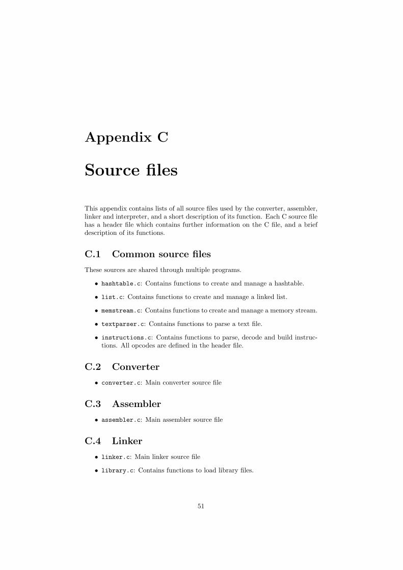
Appendix C
Source files
This appendix contains lists of all source files used by the converter, assembler,linker and interpreter, and a short description of its function. Each C source filehas a header file which contains further information on the C file, and a briefdescription of its functions.
C.1 Common source files
These sources are shared through multiple programs.
• hashtable.c: Contains functions to create and manage a hashtable.
• list.c: Contains functions to create and manage a linked list.
• memstream.c: Contains functions to create and manage a memory stream.
• textparser.c: Contains functions to parse a text file.
• instructions.c: Contains functions to parse, decode and build instruc-tions. All opcodes are defined in the header file.
C.2 Converter
• converter.c: Main converter source file
C.3 Assembler
• assembler.c: Main assembler source file
C.4 Linker
• linker.c: Main linker source file
• library.c: Contains functions to load library files.
51
APPENDIX C. SOURCE FILES 52
C.5 Interpreter
• interpreter.c: Main interpreter source file
• interpreter_engine.c: The actual interpreter (contains execution code)
• io.c: Contains several IO functions for Windows and Linux
C.6 Bootstrap code
• bootstrap.bc: Bootstrap code for standard programs (calls main)

Appendix D
File formats
This chapter contains the format specifications of all intermediate files gener-ated.
D.1 Bytecode file format
Bytecode files (both the original LCC generated files, as the modified bytecodefiles consist of plain textfiles. Each line contains one instruction or assemblerdirectives, the supported instructions and directives, as well as there format canbe found in chapter 3 and appendix A.
Any additional spaces, tabs and whitelines are discarded by the assembler,however they are never generated by LCC. Comment can be added using the “#”character. All text after a “#” is ignored, until the end of the line. Note thatcomment is not part of the LCC Bytecode specifictations, but is accepted bythe assembler.
D.2 Assembly file format
The assembly files are binary representations of bytecode files. An assemblyfile can be disassembled into a bytecode file without losing any information(this excludes comment and formatting). Each assembly file contains a table oflabels found in the bytecode file, binary data for each segments, and bitmapsfor each segment which point out the location of label positions within thesegments. Each bitmap bit represents one segment byte, and each one in thebitmap denotes the representing byte in the segment contains a label location.Before resolving all addresses, the segments contain unique label id’s insteadof addresses. The address resolver can thus check the bitmap for ones, readthe label id from the segment on the same byte-location as the bitmap onesbit-location, find the labels address and write the address back to the segment.The formats of the assembly file, the label table and the individual labels areshown respectively in tables D.1, D.2 and D.3. In table D.4 the different labelflags codes can be found. Since several fields in a file have sizes which dependon the data, the size of a field, and thus the offset of the next field, is notknown. Therefore, in all tables, the sizes of each field are placed rather thanthe locations where they can be found.
53
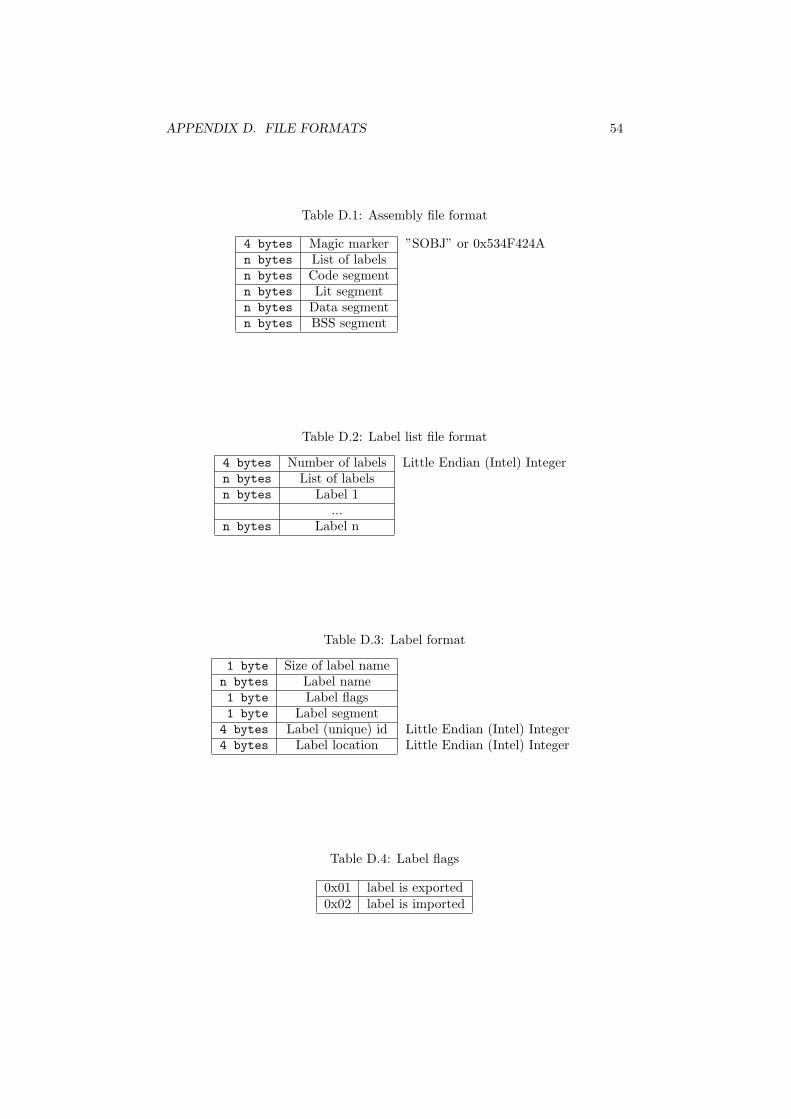
APPENDIX D. FILE FORMATS 54
Table D.1: Assembly file format
4 bytes Magic marker ”SOBJ” or 0x534F424An bytes List of labelsn bytes Code segmentn bytes Lit segmentn bytes Data segmentn bytes BSS segment
Table D.2: Label list file format
4 bytes Number of labels Little Endian (Intel) Integern bytes List of labelsn bytes Label 1
...n bytes Label n
Table D.3: Label format
1 byte Size of label namen bytes Label name1 byte Label flags1 byte Label segment4 bytes Label (unique) id Little Endian (Intel) Integer4 bytes Label location Little Endian (Intel) Integer
Table D.4: Label flags
0x01 label is exported0x02 label is imported

APPENDIX D. FILE FORMATS 55
Any function or variable which is accesible in other files, will be marked asexported. Any function or variable which is accessed, but not declared in thecurrent file will be marked imported. For every imported variable or function,an exported variable or function must exist in any file also passed to the linker.
Table D.5: Segment codes
unkown 0x00code 0x02lit 0x04data 0x08bss 0x01
Table D.6: Segment format
4 bytes Segment size Little Endian (Intel) Integern bytes Segment datan bytes Label bitmap Will be eight times smaller than the segment data
Finally, in tables D.5 and D.6 the segment data format is shown. Since theBSS segment does not contain any usefull information (uninitialized variables),only the size for this segment is stored in the assembly file, and the segmentdata and label bitmap are omitted.
D.3 Code segment format
The code segment is filled with instructions. Each instruction is coded into abinary form and then written to the binary assembly file. Each instruction has a16-bit opcode, containing the actual opcode, the type (pointer, integer, etc. . . )and size (in bytes), just as they are generated by LCC. Some instructions alsoget a parameter. The encoding of instructions can be found in the tables D.7,D.8 and D.9. The size and coding of parameters can also be found in D.9 (thecharacters in this column are the same as those used in Table A.2).
Table D.7: Instruction format
Bit index Description15-09 opcode (see Table D.9)08-06 instruction operand type (table:instructiontype2)05-02 log2 of instruction operand size01-00 not used

APPENDIX D. FILE FORMATS 56
The INDIR and ASGN parameters are only generated by LCC when fetchingor assigning a structure. In the binary assembly files, this parameter is alwaysgenerated, and should be set to 0 for all other operand types.
D.4 Library file format
The library file is a simple container format for several assembly files. Theassembly files are dumped right after eachother in the library file. Thereforethe library file must be read sequencially, since the exact position of the secondfile is only known when the first file is completely read. The format of a libraryfile is shown in table D.10.
D.5 Executable file format
The executable file generated by the linker contains the combined binary seg-ments. It has no header, nor a real format. The segments are written in thefollowing order: code, lit, data. The bss segment is not placed in the exe-cutable file, instead the bootstrap code which is placed at address 0 allocatesspace for the bss segment.
Table D.8: Instruction type format
Type CodingFloating point (F) 0x03Signed integer (I) 0x02Unsigned integer (U) 0x04Pointer (P) 0x01Void (V) 0x05Structure (B) 0x06

APPENDIX D. FILE FORMATS 57
Table D.9: LCC InstructionsOperator Type Suffixes Parameter size CodingADDRF ...P.. p 0x01ADDRG ...P.. p 0x02ADDRL ...P.. p 0x03CNST FIUP.. fdx csilh csilh p 0x04BCOM .IU... 0x05CVF FI.... i i 0x06CVI FIU... i i i 0x07CVP ..U... i 0x08CVU .IUP.. i i i 0x09INDIR FIUP.B i i i i i 0x0ANEG FI.... 0x0BADD FIUP.. 0x0CBAND .IU... 0x0DBOR .IU... 0x0EBXOR .IU... 0x0FDIV FIU... 0x10LSH .IU... 0x11MOD .IU... 0x12MUL FIU... 0x13RSH .IU... 0x14SUB FIU... 0x15ASGN FIUP.B i i i i i 0x16EQ FIU... p i i 0x17GE FIU... p i i 0x18GT FIU... p i i 0x19LE FIU... p i i 0x1ALT FIU... p i i 0x1BNE FIU... p i i 0x1CARG FIUP.B i i i i i 0x1DCALL FIUPVB 0x1ERET FIUPVB 0x1FJUMP ....V. 0x20HALT ....V. 0x7FARGSTACK ....V. i 0x22VARSTACK ....V. i 0x23SYSCALL FIUP.. 0x27SAVESTATE ....V. 0x28NEWSTACK ....V. 0x29DISCARD FIUP.. 0x30

APPENDIX D. FILE FORMATS 58
Table D.10: Library format4 bytes Magic marker ”SLIB” or 0x534C49424 bytes Number of assembly files Little Endian (Intel) Integern bytes Assembly file 1
...n bytes Assembly file n

Appendix E
User manual
This chapter contains very brief user interfaces on how to run a C project onthe interpreter.
E.1 LCC
The LCC manual can be found on http://www.cs.princeton.edu/software/lcc/.A standard installation of LCC can be used to create bytecode files, but it isrecomended to install the new bytecode backend which is discussed in section4.2. Generating bytecode can either be done by the RCC compiler part of LCC, orby LCC itself. The difference is that LCC first calls the C preprocessor, then RCC,and then the systems assembler and linker, which can be skipped by using the ‘-S’ argument. To select the bytecode backend, the parameter ‘-target=bytecode’must be given to RCC, or ‘-Wf-target=bytecode’ to LCC. ‘bytecode’ may needto be replaced by ‘xbytecode’ when the new backend is used.
Note that when using LCC, either the LCC C preprocessor, or the GNU Cpreprocessor can be used. Both need to be pointed to the right header filedirectory (not the systems header files) found in libs. The LCC driver mayneed to be modified for this. Information about modifieng the LCC driver canbe found on the LCC website.
E.2 Converter
The converter converts LCC Bytecode files into slightly customized LCC Bytecodefiles. The assembler will only accept customized LCC Bytecode files, so the con-verter must be used on LCC Bytecode files before passing them to the assembler.The converter must be provided an input and output file:
converter <inputfile> -o <outputfile>
E.3 Assembler
The assembler converts modified bytecode files into binary assembly files. Thebinary assembly files can later be fed to the linker, which combines several
59

APPENDIX E. USER MANUAL 60
binary assembly files into one executable file. The assembler must be providedwith an input and output file:
assembler <inputfile> -o <outputfile>
E.4 Linker
The linker combines several binary assembly files, the bootstrap code, and sev-eral library functions if needed, and places them into a single executable file.In addition, the linker can also be used to generate library files. All input filesspecified must be binary assembly files, generated by the assembler, the outputfile is either a library file, or an executable file:
linker <inputfile> [<inputfile>...] [-lib <libdir>][-buildlib] [-v] -o <outputfile>
If the -buildlib parameter places all input files in a library file denoted byoutputfile. The -lib and -v arguments are ignored. When an executable fileis created, the linker will search in each directory specified by the -lib argument(multiple directories require multiple -lib arguments) for library functions andincludes them into the output file when required. When the -v argument isused, the linker will print all addresses of public functions and variables to theconsole, which can be used when embedding the interpreter.
E.5 Interpreter
The interpreter executes executable files generated by the linker. When it isused as a standalone application it can be executed from the commandline:
interpreter <inputfile> [m <memorysize>] [-nd][-t <tracefile>] [-a <analysisfile>]
Besides an input file, which must be specified, two output files can be specified,an analysis file and a trace file. When an analysis file is specified, it will befilled with information on the amount of instructions executed, the amount ofmemory used, and how many each individual instruction type was executed.The result is stored in a tab delimited text file. When a trace file is specified, oneach clocktick the current instruction, machine state and stack is written to thetrace file. Note that this file will become very large on big programs. Finally,the nd parameter can be used to ignore the DISCARD instruction and shouldonly be used for testing purpses.
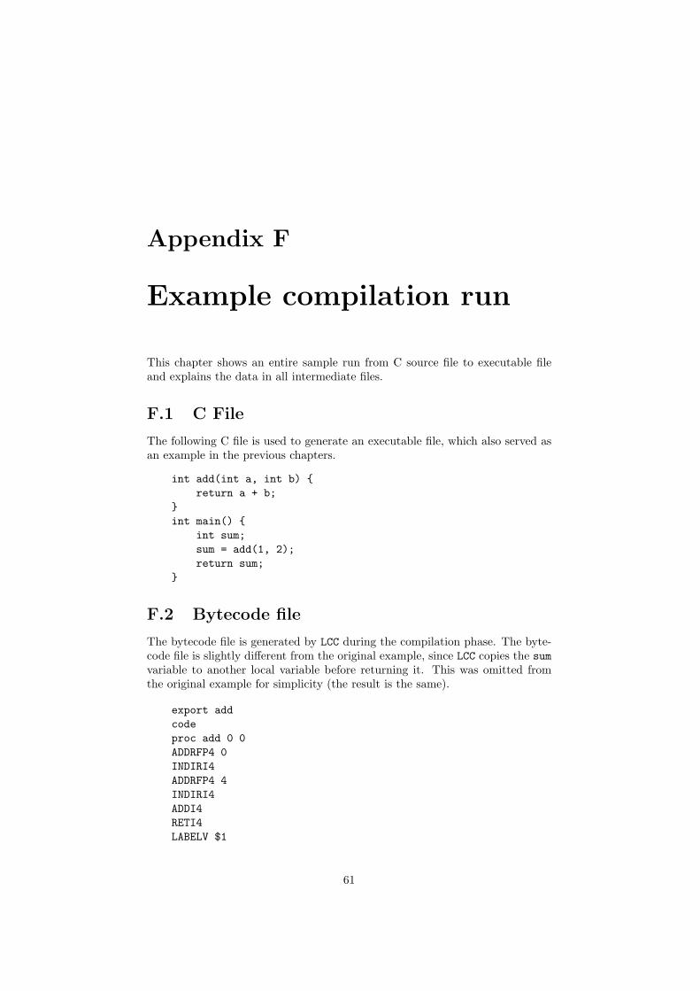
Appendix F
Example compilation run
This chapter shows an entire sample run from C source file to executable fileand explains the data in all intermediate files.
F.1 C File
The following C file is used to generate an executable file, which also served asan example in the previous chapters.
int add(int a, int b) {return a + b;
}int main() {
int sum;sum = add(1, 2);return sum;
}
F.2 Bytecode file
The bytecode file is generated by LCC during the compilation phase. The byte-code file is slightly different from the original example, since LCC copies the sumvariable to another local variable before returning it. This was omitted fromthe original example for simplicity (the result is the same).
export addcodeproc add 0 0ADDRFP4 0INDIRI4ADDRFP4 4INDIRI4ADDI4RETI4LABELV $1
61

APPENDIX F. EXAMPLE COMPILATION RUN 62
endproc add 0 0export mainproc main 8 8CNSTI4 1ARGI4CNSTI4 2ARGI4ADDRLP4 4ADDRGP4 addCALLI4ASGNI4ADDRLP4 0ADDRLP4 4INDIRI4ASGNI4ADDRLP4 0INDIRI4RETI4LABELV $2endproc main 8 8
F.3 Custimized bytecode file
The customized bytecode file is a slightly altered version of the bytecode file,for easier assembling. All changes made can be found in Section 4.3.
export addcode### procedure add:label addSAVESTATEP4ARGSTACKV 0VARSTACKV 0ADDRFP4 0INDIRI4ADDRFP4 4INDIRI4ADDI4RETI4label $1RETV### end procedure addexport main### procedure main:label mainSAVESTATEP4ARGSTACKV 8VARSTACKV 8CNSTI4 1ARGI4 0

APPENDIX F. EXAMPLE COMPILATION RUN 63
CNSTI4 2ARGI4 4ADDRLP4 4ADDRGP4 addCALLI4ASGNI4ADDRLP4 0ADDRLP4 4INDIRI4ASGNI4ADDRLP4 0INDIRI4RETI4label $2RETV### end procedure main
F.4 Binary assembly file
The binary assembly file contains the binary representation of the customizedbytecode file. It is printed completely in hexadecimal, since most of the datais binary. Using the ‘#’ character, comment is added to the file to explain alldata.
# file id: SOBJ0x0000: 53 4F 42 4A# total of 4 labels0x0004: 04 00 00 00# label main# main is 4 characters long0x0008: 04# "main"0x0009: 6D 61 69 6E# the flag of main is 0x01 (exported)0x000D: 01# the segment of main is 0x02 (code)0x000E: 02# the unique id of this label is 0x030x000F: 03 00 00 00# the address of main in the code segment is 0x2C0x0013: 2C 00 00 00# label $10x0017: 02 24 31 00 02 02 00 00 00 2A 00 00 00# label $20x0024: 02 24 32 00 02 04 00 00 00 8C 00 00 00# label add0x0031: 03 61 64 64 01 02 01 00 00 00 00 00 00 00# 90h bytes code segment size0x003F: 90 00 00 00# label add
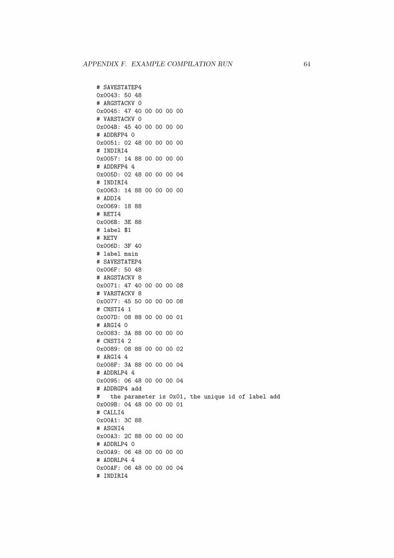
APPENDIX F. EXAMPLE COMPILATION RUN 64
# SAVESTATEP40x0043: 50 48# ARGSTACKV 00x0045: 47 40 00 00 00 00# VARSTACKV 00x004B: 45 40 00 00 00 00# ADDRFP4 00x0051: 02 48 00 00 00 00# INDIRI40x0057: 14 88 00 00 00 00# ADDRFP4 40x005D: 02 48 00 00 00 04# INDIRI40x0063: 14 88 00 00 00 00# ADDI40x0069: 18 88# RETI40x006B: 3E 88# label $1# RETV0x006D: 3F 40# label main# SAVESTATEP40x006F: 50 48# ARGSTACKV 80x0071: 47 40 00 00 00 08# VARSTACKV 80x0077: 45 50 00 00 00 08# CNSTI4 10x007D: 08 88 00 00 00 01# ARGI4 00x0083: 3A 88 00 00 00 00# CNSTI4 20x0089: 08 88 00 00 00 02# ARGI4 40x008F: 3A 88 00 00 00 04# ADDRLP4 40x0095: 06 48 00 00 00 04# ADDRGP4 add# the parameter is 0x01, the unique id of label add0x009B: 04 48 00 00 00 01# CALLI40x00A1: 3C 88# ASGNI40x00A3: 2C 88 00 00 00 00# ADDRLP4 00x00A9: 06 48 00 00 00 00# ADDRLP4 40x00AF: 06 48 00 00 00 04# INDIRI4

APPENDIX F. EXAMPLE COMPILATION RUN 65
0x00B5: 14 88 00 00 00 00# ASGNI40x00BB: 2C 88 00 00 00 00# ADDRLP4 00x00C1: 06 48 00 00 00 00# INDIRI40x00C7: 14 88 00 00 00 00# RETI40x00CD: 3E 88# label $2# RETV0x00CF: 3F 40# alignment bytes, to make segment size a multiple of 80x00D1: 00 00# label bitmap for code segment (0x90/8 = 0x12 bytes)# the 3C on 0x00DE (4 ones starting at bit 90)# represent a label reference at byte 90 in the code# segment (which starts at 0x43). A label reference# is placed at 0x9D; the parameter of ‘ADDRGP4 add’0x00D3: 00 00 00 00 00 00 00 000x00DB: 00 00 00 3C 00 00 00 000x00E3: 00 00# size of lit segment (0 bytes)0x00E5: 00 00 00 00# the size of the lit segment is 0, thus there is no# lit segment or bitmap data present in the file# size of data segment (0 bytes)0x00E9: 00 00 00 00# size of bss segment (0 bytes)0x00ED: 00 00 00 00
F.5 Executable file
The executable file contains the combined binary segments of the loader and theassembly file shown in the previous section. It starts with the code segment ofthe loader, followed by the code segment of the assembly file from the previoussection. This piece of data is the same as the data from the previous section,except for the parameter of the ADDRGP4 add instruction, it is now correctly setto the absolute address of the add function. After the code segments, the litand bss segments of the loader are located, since the example does not use thesesegments, they also don’t appear in the executable.
Bibliography
[1] 8051 Instruction set: http://www.win.tue.nl/ aeb/comp/8051/set8051.html(October 2005)
[2] Cipher Game Engine Implementation of LCC Bytecode:http://www.rik.org/articles/ciphervm.htm
[3] A.J.C. van Gemund, Personal Communication (September 2004)
[4] Dick Grune, Henri E. Bal, Ceriel J.H. Jacobs and Koen G. Langendoen:Modern Compiler Design, John Wiley & Sons Ltd. (2003)
[5] David R. Hanson and Christopher W. Fraser: A Retargetable C Compiler,Addison-Wesley (1995)
[6] David R. Hanson and Christopher W. Fraser: The lcc .4x Code-GenerationInterface (2003)
[7] John L. Hennessy and David A. Patterson: Computer Architecture: AQuantitative Approach, Morgan Kaufmann (2003)
[8] John L. Hennessy and David A. Patterson: Computer Orginazation & De-sign: The Hardware/Software Interface, Morgan Kaufmann (1998)
[9] i386 Instruction set: http://www.logix.cz/michal/doc/i386/chp17-00.htm(October 2005)
[10] Brian W. Kernighan and Dennis M. Ritchie: The C Programming Lan-guage, Prentice Hall P T R (2004)
[11] Jens Kretzschmar: Extending the porting of the GCC-Backend forTMS320C6x VLIW-Architecture (2004)
[12] Hans-Peter Nilsson: Porting The Gnu C Compiler for Dummies (2004)
[13] Quake 3 Virtual Machine Implementation of LCC Bytecode:http://www.icculus.org/˜phaethon/q3mc/q3vm specs.html (October2005)
[14] SDCC Programmers: SDCC Compiler User Guide (2005)
66