
Broj 11–12
104
Broj 11–12 Novembar–decembar, 2011. SADRŽAJ Number 11–12 November–December, 2011 CONTENTS Kratak osvrt na studije građevinarstva i arhitekture prema bolonj- skom procesu, Prof. dr Živojin PRAŠČEVIĆ, dipl. građ. inž. 631 Short Review on Studies of Civil Engineering and Architecture Accordig to Bologna Process, Prof. Živojin PRAŠČEVIĆ, Civ. Eng. Ph.D. 631 Priznanja u jubilarnoj godini, Branko BOJOVIĆ, dipl. inž. arh. 635 Recognitions in the Jubilee Year, Branko BOJOVIĆ, Arch. 635 Prof. dr Zlatko MARkOVIĆ, dipl. građ. inž., Jelena DRAgAŠ, dipl. građ. inž.: Savre- meni koncept projektovanja konstrukcija od aluminijumskih legu- ra prema Evrokodu 9 Pregledni rad Biblid: 0350-5421, 11–12 (2011), str. 639–650 639 Prof. Zlatko MARkOVIĆ, Civ. Eng. Ph.D., Jelena DRAgAŠ, Civ. Eng.: The Contem- porary Design Concept of Aluminum Alloys Structures According to Eurocode 9 Review paper Biblid: 0350-5421, 11–12 (2011), pp 639–650 639 Peter A. MAkAChIA: Stambene strategije u kenijskim gradovima i transformacije podstaknute od samih stanovnika – Primeri na- selja u Najrobiju Originalni naučni rad Biblid: 0350-5421, 11–12 (2011), str. 651–670 651 Peter A. MAkAChIA: Housing Strategies in Kenyan Towns and Dweller-Initiated Transformations – Case Estates from Nairobi Originaly scientific paper Biblid: 0350-5421, 11–12 (2011), pp 651–670 651 Doc. dr Ljiljana ALEksIĆ, dipl. inž. arh., dr Vesna kOsORIĆ, dipl. inž. arh.: Sunčeva energija za decu: projekat dogradnje O. Š. „Dragoj- lo Dudić“ u Beogradu Originalni naučni rad Biblid: 0350-5421, 11–12 (2011), str. 671–680 671 Ljiljana ALEksIĆ, Arch. Ph.D., Vesna kOsORIĆ, Arch. Ph.D.: Solar Energy For Kids: Design of Primary School “Dragojlo Dudić” Up- grade in Belgrade Originaly scientific paper Biblid: 0350-5421, 11–12 (2011), pp 671–680 671 Prof. dr Vladimir RADOJIČIĆ, dipl. građ. inž.: Most na reci Garvanici, – pritoci Južne Morave Originalni naučni rad Biblid: 0350-5421, 11–12 (2011), str. 681–682 681 Prof. Vladimir RADOJIČIĆ, Civ. Eng. Ph.D.: The Bridge Over Garva- nica River – South Morava River Tributary Originaly scientific paper Biblid: 0350-5421, 11–12 (2011), pp 681–682 681 Maria I. TODOROVskA, Mohammad T. RAhMAnI: Identifikacija konstruktivnog sistema zgrada pomoću slojevitih modela zgrada i funkcije impulsa sistema Originalni naučni rad Biblid: 0350-5421, 11–12 (2011), str. 683–697 683 Maria I. TODOROVskA, Mohammad T. RAhMAnI: Structural Sy- stem Identification of Buildings Using Layered Building Models and Impulse Responses Originaly scientific paper Biblid: 0350-5421, 11–12 (2011), pp 683–697 683 Doc. dr Ilija LALOŠEVIĆ, dipl. inž. arh.: Svojstva istorijskih zidanih konstrukcija u seizmičkim zonama (primjer Boke Kotorske) Pregledni rad Biblid: 0350-5421, 11–12 (2011), str. 698–703 698 Ilija LALOŠEVIĆ, Arch. Ph.D.: Characteristics of the Historic Ma- sonry Structures in Seismic Prone Regions (Case Study of Boka Kotorska) Review paper Biblid: 0350-5421, 11–12 (2011), pp 698–703 698 Prof. dr Milan TRIfkOVIĆ, dipl. geod. inž.: Primena geodezije u istra- živanju uticaja seizmičkih procesa na tlo i inženjerske strukture Pregledni rad Biblid: 0350-5421, 11–12 (2011), str. 704–709 704 Prof. Milan TRIfkOVIĆ, geodesy, Ph.D.: Geodesy Utilization for De- termination Seismic Processes Influence on Land Surface and Engineering Structure Review paper Biblid: 0350-5421, 11–12 (2011), pp 704–709 704 Mr Dejan BELJAkOVIĆ, dipl. građ. inž., mr Bojana DRAŠkOVIĆ, dipl. prav., mr Aleksandar MILAJIĆ, dipl. građ. inž.: Odgovorni izvođač ra- dova u graditeljstvu stručni rad Biblid: 0350-5421, 11–12 (2011), str. 710–716 710 Dejan BELJAkOVIĆ, Civ. Eng. M.sc., Bojana DRAŠkOVIĆ, Jur. M.sc., Aleksandar MILAJIĆ, Civ. Eng. M.sc.: Project Manager in Ci- vil Engineering Professional paper Biblid: 0350-5421, 11–12 (2011), pp 710–716 710 POGLEDI I MIŠLJENJA Elza Milenković, DIA: Istraživanja u knjizi Ranka Radovića 717 IZ INOSTRANE PRAKSE Dušan Prodanović, DIA: Uzorno organizovana komora arhitekata Ba- den-Virtemberga 721 VESTI I SAOPŠTENJA • Stručno-naučni skup „Vodovod i kanalizacija '11“ • Zaključci VI Kongesa Ciglarske industrije Srbije sa međunarod- nim učešćem • Izveštaj i zaključci sa IV naučno-stručnog savetovanja „Geoteh- nički aspekti građevinarstva“, održanog na Zlatiboru od 01.11.– 04.11.2011. god. 726 728 729 IN MEMORIAM • Vojislav Korać • Milan R. Tomić 731 732 ČASOPIS UDRUŽENJA INŽENJERA GRAĐEVINARSTVA, GEOTEHNIKE, ARHITEKTURE I URBANISTA „IZGRADNJA“ 11000 Beograd, Kneza Miloša 7a, Srbija MAGAZINE OF THE ASSOCIATION OF CIVIL ENGINEERS, GEOTECHNICAL ENGINEERS, ARCHITECTS AND TOWN PLANERS „IZGRADNJA“ 11000 Beograd, Kneza Miloša 7a, Serbia
Transcript of Broj 11–12
Broj 11–12Novembar–decembar, 2011.SADRŽAJ
Number 11–12November–December, 2011CONTENTS
Kratak osvrt na studije građevinarstva i arhitekture prema bolonj-skom procesu, Prof. dr Živojin PRAŠČEVIĆ, dipl. građ. inž. 631
Short Review on Studies of Civil Engineering and Architecture Accordig to Bologna Process, Prof. Živojin PRAŠČEVIĆ, Civ. Eng. Ph.D. 631
Priznanja u jubilarnoj godini, Branko BOJOVIĆ, dipl. inž. arh. 635 Recognitions in the Jubilee Year, Branko BOJOVIĆ, Arch. 635Prof. dr Zlatko MARkOVIĆ, dipl. građ. inž., Jelena DRAgAŠ, dipl. građ. inž.: Savre-meni koncept projektovanja konstrukcija od aluminijumskih legu-ra prema Evrokodu 9Pregledni radBiblid: 0350-5421, 11–12 (2011), str. 639–650 639
Prof. Zlatko MARkOVIĆ, Civ. Eng. Ph.D., Jelena DRAgAŠ, Civ. Eng.: The Contem-porary Design Concept of Aluminum Alloys Structures According to Eurocode 9Review paperBiblid: 0350-5421, 11–12 (2011), pp 639–650 639
Peter A. MAkAChIA: Stambene strategije u kenijskim gradovima i transformacije podstaknute od samih stanovnika – Primeri na-selja u NajrobijuOriginalni naučni radBiblid: 0350-5421, 11–12 (2011), str. 651–670 651
Peter A. MAkAChIA: Housing Strategies in Kenyan Towns and Dweller-Initiated Transformations – Case Estates from NairobiOriginaly scientific paperBiblid: 0350-5421, 11–12 (2011), pp 651–670 651
Doc. dr Ljiljana ALEksIĆ, dipl. inž. arh., dr Vesna kOsORIĆ, dipl. inž. arh.: Sunčeva energija za decu: projekat dogradnje O. Š. „Dragoj-lo Dudić“ u BeograduOriginalni naučni radBiblid: 0350-5421, 11–12 (2011), str. 671–680 671
Ljiljana ALEksIĆ, Arch. Ph.D., Vesna kOsORIĆ, Arch. Ph.D.: Solar Energy For Kids: Design of Primary School “Dragojlo Dudić” Up-grade in BelgradeOriginaly scientific paperBiblid: 0350-5421, 11–12 (2011), pp 671–680 671
Prof. dr Vladimir RADOJIČIĆ, dipl. građ. inž.: Most na reci Garvanici, – pritoci Južne MoraveOriginalni naučni radBiblid: 0350-5421, 11–12 (2011), str. 681–682 681
Prof. Vladimir RADOJIČIĆ, Civ. Eng. Ph.D.: The Bridge Over Garva-nica River – South Morava River TributaryOriginaly scientific paperBiblid: 0350-5421, 11–12 (2011), pp 681–682 681
Maria I. TODOROVskA, Mohammad T. RAhMAnI: Identifikacija konstruktivnog sistema zgrada pomoću slojevitih modela zgrada i funkcije impulsa sistemaOriginalni naučni radBiblid: 0350-5421, 11–12 (2011), str. 683–697 683
Maria I. TODOROVskA, Mohammad T. RAhMAnI: Structural Sy-stem Identification of Buildings Using Layered Building Models and Impulse ResponsesOriginaly scientific paperBiblid: 0350-5421, 11–12 (2011), pp 683–697 683
Doc. dr Ilija LALOŠEVIĆ, dipl. inž. arh.: Svojstva istorijskih zidanih konstrukcija u seizmičkim zonama (primjer Boke Kotorske)Pregledni radBiblid: 0350-5421, 11–12 (2011), str. 698–703 698
Ilija LALOŠEVIĆ, Arch. Ph.D.: Characteristics of the Historic Ma-sonry Structures in Seismic Prone Regions (Case Study of Boka Kotorska)Review paperBiblid: 0350-5421, 11–12 (2011), pp 698–703 698
Prof. dr Milan TRIfkOVIĆ, dipl. geod. inž.: Primena geodezije u istra-živanju uticaja seizmičkih procesa na tlo i inženjerske strukturePregledni radBiblid: 0350-5421, 11–12 (2011), str. 704–709 704
Prof. Milan TRIfkOVIĆ, geodesy, Ph.D.: Geodesy Utilization for De-termination Seismic Processes Influence on Land Surface and Engineering StructureReview paperBiblid: 0350-5421, 11–12 (2011), pp 704–709 704
Mr Dejan BELJAkOVIĆ, dipl. građ. inž., mr Bojana DRAŠkOVIĆ, dipl. prav., mr Aleksandar MILAJIĆ, dipl. građ. inž.: Odgovorni izvođač ra-dova u graditeljstvustručni radBiblid: 0350-5421, 11–12 (2011), str. 710–716 710
Dejan BELJAkOVIĆ, Civ. Eng. M.sc., Bojana DRAŠkOVIĆ, Jur. M.sc., Aleksandar MILAJIĆ, Civ. Eng. M.sc.: Project Manager in Ci-vil EngineeringProfessional paperBiblid: 0350-5421, 11–12 (2011), pp 710–716 710
POGLEDI I MIŠLJENJAElza Milenković, DIA: Istraživanja u knjizi Ranka Radovića 717IZ INOSTRANE PRAKSEDušan Prodanović, DIA: Uzorno organizovana komora arhitekata Ba-den-Virtemberga 721VESTI I SAOPŠTENJA• Stručno-naučni skup „Vodovod i kanalizacija '11“• Zaključci VI Kongesa Ciglarske industrije Srbije sa međunarod-
nim učešćem• Izveštaj i zaključci sa IV naučno-stručnog savetovanja „Geoteh-
nički aspekti građevinarstva“, održanog na Zlatiboru od 01.11.–04.11.2011. god.
726
728
729IN MEMORIAM• Vojislav Korać• Milan R. Tomić
731732
ČASOPIS UDRUŽENJA INŽENJERA GRAĐEVINARSTVA, GEOTEHNIKE, ARHITEKTURE I URBANISTA „IZGRADNJA“11000 Beograd, Kneza Miloša 7a, Srbija
MAGAZINE OF THE ASSOCIATION OF CIVIL ENGINEERS, GEOTECHNICAL ENGINEERS, ARCHITECTS AND TOWN PLANERS „IZGRADNJA“11000 Beograd, Kneza Miloša 7a, Serbia

Ministarstvo prosvete i nauke Republike Srbije, sufinansira izdavanje
naučnog časopisa IZGRADNJA
Časopis „Izgradnja“ izlazi uz finansijsku podršku
INŽENJERSKE KOMORE SRBIJE11000 Beograd,
Bulevar vojvode Mišića 37Fax 2648 523
www. Ingkomora.org.rsE-mail: [email protected]
GENERALNI SPONZORI
SAOBRAĆAJNI INSTITUT CIP 11000 Beograd, Nemanjina 6/IV Republika Srbija, Tel: 011/3616 929, 3618 287, faks: 011/3616 757 www.sicip.co.rs, E-mail: [email protected]
„MAŠINOPROJEKT KOPRING“11000 Beograd, Dobrinjska 8aTel. 011/3635 700, faks 011/2643 995E-mail: [email protected]
JKP „Beograd put“11000 Beograd, Nušićeva 21Telefon: 011/3302 800Faks: 011/3302 855Email: [email protected]
Institut za arhitekturu i urbanizam Srbije11000 Beograd, Bulevar kralja Aleksandra 73/2 Telefon: 011/3370 091www.iaus.ac.rsE-mail: [email protected]
Institut za puteve a.d.11000 Beograd, Kumodraška 257Tel.011/3976 374, faks: 011/2466 866www.highway.rse-mail: [email protected]
Institut za vodoprivredu „Jaroslav Černi“ a.d.11226 Pinosava, Beograd, Jaroslava Černog 80Tel: 011/3906 450, faks: 011/3906 481www.jcerni.orge-mail: [email protected]
Časopis “Izgradnja” objavljuje naučne i stručne radove i ostale priloge iz oblasti građevi-narstva, arhitekture, urbanizma i industrije građevinskog materijala. Radovi se kategorizuju prema sledećim međunarodno priznatim pravilima:
A. NAUČNI I STRUČNI RADOVI1. Originalni naučni rad sadrži neobjavljene rezultate izvornih istraživanja; u njemu su na-
učne informacije tako izložene da se eksperiment može ponoviti i tom prilikom postići opisani rezultati unutar dozvoljenih granica eksperimentalne greške, odnosno sa taćnošću koju navodi autor. Za takav rad mora postojati mogućnost da se ponove autorova opažanja, teoretski izvodi, analize i proračuni i da se zauzmu stavovi i donesu mišljenja o autorovim zaključcima i rezulatima.
2. Prethodno saopštenje je naučni rad koji sadrži jedan ili više naučnih podataka koji za-htevaju hitno objavljivanje; to saopštenje ne mora imati dovoljno pojedinosti koje omogućavaju po-navljanje ili potpunu proveru rezultata. U ovu kategoriju radova razvrstavaju se, ako sadrže naučne doprinose, ili kraće kritike, komentari i beleške o nekom publikovanom radu ili naučnom problemu.
3. Pregledni rad je naučni rad koji sadrži celovit izveštaj o nekom posebnom pitanju ili po-dručju a sastavljen je na osnovu publikovanih informacija. koje su za tu priliku sakupljene, analizirane i objašnjene. Autor je dužan da pruži što potpunije podatke o publikovanim radovima koji su bitnije doprineli razvoju određenog pitanja ili područja, odnosno koji bi tom razvoju doprineli da nisu previđeni ili zanemareni.
4. Stručni rad predstavlja korisne priloge iz područja struke a iznesena zapažanja ne mo-raju predstavljati stručnu novost u širem smislu: to su korisna i vredna iskustva u primeni poznatih naučnih dostignuća koja doprinose širenju stručnih znanja i njihovom ispravnom korišćenju u praksi graditeljstva.
B. OSTALI PRILOZIOstali prilozi obuhvataju prikaze projektnih rešenja, gradilišta, pogona i fabrika, stručne pri-
kaze i osvrte na pojedine aktuelne teme i pitanja iz oblasti građevinarstva, arhitekture, urbanizma i industrije građevinskog materijala, poglede i mišljenja, napise iz istorije struke i graditeljstva, prikaze knjiga, bibliografske, društveno stručne i komercijalne informacije, naučne i stručne zanimljivosti i dr.
Naučni i stručni rad mora biti originalan, još neobjavljen, i ne sme biti istovremeno ponuđen drugom časopisu. Autor je odgovoran za izneseni sadržaj i mora sam obezbediti eventualno potrebne saglasnosti za objavljivanje nekih podataka, slika ili fotosa koje koristi u radu. Rukopisi radova se recenziraju. Recenzent predlaže kategorizaciju rada a odluku donosi Uredivački odbor časopisa.
Radovi i ostali prilozi mogu imati obim do jednog autorskog tabaka (30.000 slovnih znakova); oni mogu biti duži samo uz saglasnost Uredništva Časopisa. Uredništvo zadržava pravo da, saglasno uređivačkoj politici Časopisa i/ili mišljenju recenzenta, donese odluku o prihvatanju ili neprihvatanju za objavljivanje svakog pojedinog predloženog rada ili priloga.
Za detaljna tehnička uputstva o pripremi rukopisa autori treba da se obrate Redakciji Časopi-sa. Rukopisi se predaju u dva primerka, sa rezimeom obima do 100 reči. Na kraju rezimea autor treba da navede do šest ključnih reči. Prevod rezimea na engleski jezik obezbeđuje Redakcija Časopisa. Za objavljene radove i priloge rukopisi se ne vraćaju.
Uz naslov rada ili priloga treba napisati puno prezime i ime autora, njegovo stručno i naučno zvanje, naziv ustanove ili preduzeća u kome radi i adresu stana. Autori radovi i priloga dobijaju besplat-no jedan primerak Časopisa u kome je rad objavljen.
OBAVEŠTENJE AUTORIMA I SARADNICIMAREDAkCIOnI ODBOR: Dimitrije Mladenović, predsednik, Branko Bojović, Miloš Bojović, Zoran Lazović, Milan Maksimović, Dušan Milović, slobodan Otović, Živojin Praščević, Ljubinko Pušić, Darko Radović, Tomislav Radojičić, Miodrag ferenčakv. d. gLAVnOg I ODgOVORnOg UREDnIkA: Branko BojovićUREĐIVAČkI ODBOR: Branko Bojović, v.d. glavnog i odgovornog urednika, Živojin PraščevićsEkRETAR REDAkCIJE: svetlana UroševićMARkETIng: Dušan MilosavljevTEhnIČkO UREĐEnJE: kvartet VIZDAVAČ: Časopis Udruženja inženjera građevinarstva, geotehnike, arhitekture i urbanista „Izgradnja“, 11000 Beograd, kneza Miloša 7a/ll, Tel/fax: +381 (0) 11 3243-563 E-mail: [email protected], tekući račun: 295-1243120-14 kod „srpske banke“ a.d. Beograd.ŠTAMPA: „hektor print“, novi BeogradCIP – Каталогизација у публикацији Народна библиотека Србије, Београд 624+71/72(05) Issn 0350-5421 = lzgradnja COBIss.sR-ID 55831
Ovaj broj 11–12 našeg časopisa izašao je i uz finansijsku pomoć
Preduzeće za održavanje i izgradnju puteva „Magistrala“ a.d. Beograd, Bulevar kralja Aleksandra 282/1
Telefoni: 011-3820-339; 3820-340; faks: 011-3820-280 E-mail adresa: [email protected]
KRATAK OSVRT NA STUDIJE GRAĐEVINARSTVA I ARHITEKTURE PREMA BOLONJSKOM PROCESU
SHORT REVIEW ON STUDIES OF CIVIL ENGINEERING AND ARCHITECTURE ACCORDIG TO BOLOGNA PROCESS
U uvodniku „Izgradnje“ br. 9–10 za 2010. godinu nаpisao sam osvrt na bolonjsku deklaraciju visokoškolskog obrazovanja i prikazao osnovne principe i ciljeve ovog važ-nog međunarodnog dokumenta koji je potpisalo i prihvatilo više od 40 evropskih zema-lja, među kojima i Republika Srbija. U uvodniku ovog broja ukazuje se na neke aspek-te primene ove deklaracije u našoj zemlji i sprovedenu reformu prema Zakonu o viso-kom obrazovanju.
Reforma visokoškolskog obrazovanja je u poslednjih desetak godina izvršena u svim zemljama potpisnicama deklaracije. U našoj zemlji reforma je intenzivirana po-sle donošenja Zakona o visokom obrazovanju u Skupštini Srbije septembra 2005. god. (Službeni glasnik RS 78/05) i izmena zakona u julu 2010. godine. Ovaj zakon je oba-vezao univerzitete, visoke i više škole da izvrše temeljnu reformu obrazovanja po no-vom sitemu, uveo Nacionalni savet za visoko obrazovanje i obavezu da se svi univerzi-teti, fakulteti i visoke škole akredituju.
Prema Zakonu o visokom obrazovanju ovu delatnost obavljaju: univerzitet, fakul-tet, odnosno umetnička akademija u sastavu univerziteta, akademija strukovnih studi-ja, visoka škola i visoka škola strukovnih studija. Delatnost visokog obrazovanja ostva-ruje se kroz akademske i strukovne studije na osnovu odobrenih, odnosno akreditova-nih studijskih programa. Na akademskim studijama izvodi se akademski studijski pro-gram, koji osposobljava studente za razvoj i primenu naučnih, stručnih i umetničkih dostignuća. Na strukovnim studijama se izvodi strukovni studijski program koji ospo-sobljava studente za primenu znanja i veština potrebnih za uključivanje u radni pro-ces.
Studije visokog obrazovanja se ostvaruju u tri stepena.Studije prvog stepena su osnovne akademske studije i osnovne strukovne studije.Studije drugog stepena su: diplomske akademske studije – master, specijalističke
strukovne studije i specijalističke akademske studije.Studije trećeg stepena su doktorske akademske studije.Svaki predmet iz studijskog programa iskazuje se brojem ESPB (Evropski Sistem
Prenosa Bodova) bodova, koji za prosečno angažovanje studenta u obimu od 40-to ča-sovne nedelje iznosi za jednu godinu 60. Osnovne akademske studije u trogodišnjem trajanju imaju 180, a u četvorogodišnjem trajanju 240 ESPB. Specijalističke strukov-ne studije i akademske specijalističke imaju najmanje po 60 ESPB. Diplomske aka-demske studije imaju najmanje 60 ESPB ako je prethodno ostvaren program na osnov-nim akademskim studijama od 240 ESPB ili 120 ESPB, ako je prethodno ostvaren pro-gram na osnovnim akademskim studijama od 180 ESPB. Doktorske studije imaju naj-
IZGRADNJA 65 (2011) 11–12, 631–634 631
632 IZGRADNJA 65 (2011) 11–12, 631–634
manje 180 ESPB (u koje spadaju doktorski ispiti i izrada doktorske disertacije) ako je prethodno ostvaren program od 300 ESPB na akademskim studijama. Za upis na ove studije je propisan i uslov da kandidat iz prethodnih akademskih studija u trajanju od 4 godine ima najmanju prosečnu ocenu 8 (osam).
Prema Zakonu o izmenama Zakona o visokom obrazovanju iz jula 2010. god. usta-novljena su sledeća stručna i akademska zvanja.
Lice koje završi akademske studije od najmanje 180 ESPB u trajanju od tri godine stiče stručni naziv sa naznakom zvanja prvog stepena akademskih studija (u građevi-narstvu je to građevinski inženjer). Lice koje završi osnovne akademske studije od naj-manje 240 ESPB i trajanju od najmanje četiri godine stiče stručni naziv diplomirani sa naznakom zvanja prvog stepena akademskih studija (u građevinarstvu je to diplo-mirani građevinski inženjer). Lice koje završi diplomske akademske studije stiče aka-demski naziv master sa naznakom zvanja drugog stepena akademskih studija (u gra-đevinarstvu je to diplomirani građevinski inženjer – master). Lice koje završi specija-lističke akademske studije stiče stručni naziv specijalista sa naznakom zvanja drugog stepena akademskih studija (u građevinarstvu je to diplomirani građevinski inženjer-specijalista).
Lice koje završi doktorske studije trećeg stepena stiče naučni naziv doktor nauka sa naznakom odgovarajuće oblasti (u građevinarstvu je to doktor tehničkih nauka – oblast građevinarstvo).
Lice koje završi osnovne strukovne studije stiče stručni naziv sa naznakom zvanja prvog stepena strukovnih studija (u građevinarstvu je to građevinski inženjer). Lice koje završi specijalističke strukovne studije stiče stručni naziv specijalista sa nazna-kom zvanja drugog stepena strukovnih studija (u građevinarstvu je to – građevinski inženjer specijalista).
Skraćenica stručnog naziva (na primer, diplomirani građevinski inženjer) i aka-demskog naziva master navodi se iza imena i prezimena, a skraćenica akademskog na-ziva magistar nauka (Mr) i naučnog naziva doktor nauka (Dr) ispred imena i prezi-mena.
U međunarodnom prometu i u diplomi na engleskom jeziku lice koje je završilo trogodišnje akademske studije stiče naziv bachelor, lice koje je završilo četvorogodiš-nje akademske studije stiče naziv bachelor with honours, a lice koje je završilo doktor-ske studije i odbranilo doktorsku disertaciju stiče naučni naziv PhD(Doctor of Philo-sophy), odnosno odgovarajući naziv na jeziku na koji se diploma prevodi. Lice koje je završilo strukovne studije u trajanju od tri godine stiče stručni naziv bachelor (apl.)
Stručni nazivi stečeni završavanjem studija pre donošenja ovog zakona su: • Za studije na višoj školi u trajanju do tri godine ostaje isti naziv kao i za stru-
kovne studije u trajanju od tri godine (građevinski inženjer).• Za deo studijskog programa na fakultetu ili osnovne studije od tri godine čijim
se završavanjem stiče naziv za prvi stepen visokog obrazovanja ostaje isti naziv (građe-vinski inženjer).
• Za diplomske studije na fakultetu u trajanju od četiri do šest godina (raniji na-ziv diplomirani građevinski inženjer) izjednačava se sa novim nazivom diplomirani građevinski inženjer – master.
Na Građevinskom fakultetu Univerziteta u Beogradu, prema novim studijskim pro-gramima, koji su usvojeni pre tri godine, na odsecima za građevinarstvo, koji se sada nazivaju studijski programi (Studijski program za konstrukcije, Studijski program za hidrotehniku i vodno-ekološko inženjerstvo, Studijski program za puteve i železnice i Studijski program za menadžment, tehnologiju i informatiku u građevinarstvu) osnov-ne akademske studije traju četiri godine sa 240 ESPB i posle njih se stiče stučni na-ziv diplomirani građevinski inženjer. U toku prva tri semestra je zajednička nastava (Studijski program zajedničke osnove), tako da se studenti opredeljuju za odsek, odno-
IZGRADNJA 65 (2011) 11–12, 631–634 633
sno studijski program, na kome će nastaviti studije na početku četvrtog semestra. Uve-den je veliki broj izbornih predmeta, naročito na trećoj i četvrtoj godini studija sa uku-pnim godišnjim brojem od 60 bodova. U osmom semestru se radi sintezni projekat ko-jem je dodeljeno 12 ESPB bodova. Diplomske akademske studije, koje se upisuju posle osnovnih studija, traju dva semestra i organizovane su po istim studijskim programi-ma (odsecima) kao i osnovne akademske studije. Studije su osmišljene za produbljiva-nje akademskih kompetencija studenata, kako se navodi u obrazloženju studijskih pro-grama. Na svim modulima zastupljene su specifične oblasti koje ne predstavljaju sva-kodnevnu inženjersku praksu već kompleksne oblasti koje zahtevaju dodatna znanja za njihovo sagledavanje i rešavanje. U prvom semestru izučavaju se predviđeni pred-meti (uglavnom izborni), a u drugom je predviđena stručna praksa (5 ESPB), studijski istraživački rad na pripremi diplomskog rada (10 ESPB) i diplomski rad (20 ESPB). Doktorske studije su organizovane u šest semestara. U prva tri semestra kandidat bira sedam predmeta iz širokog spiska predmeta koji su svrstani u blokove. Druga tri seme-stra su predviđena za izradu i odbranu doktorske disertacije.
U oblasti geodezije osnovne akademske studije traju tri godine, a diplomske studi-je dve godine.
Na Arhitektonskom fakultetu Univerziteta u Beogradu osnovne akademske studije (prvi stepen) traju tri godine, tj. šest semestara, sa 180 ESPB i njihovim završetkom se stiče stručni naziv inženjer arhitekture odnosno bachelor of architecture u diplomi na engleskom jeziku, tj. u međunarodnom prometu. Na ovim studijama je jedinstven pro-fil. Nastavni predmeti su svrstani u više modula, od kojih su predmeti u jednom mo-dulu u V i VI semestru izborni. Studijski programi se ostvaruju kroz tri obrazovno-na-učna, odnosno obrazovno-umetnička polja: društveno-humanističke nauke, tehničko-tehnološke nauke i umetnost. Diplomske akademske studije traju dve godine, tj. četiri semestra, sa 120 ESPB i upisuje ih student koji je završio osnovne akademske studi-je. Student se opredeljuje za jedno od tri usmerenja, odnosno studijska programa: Ar-hitektura (A), Urbanizam (U) i Arhitektonske tehnologije (AT), Integralni urbanizam (IU). Završetkom ovih studija stiče se akademski naziv diplomirani inženjer arhitektu-re – master sa naznakom usmerenja, odnosno studijskog programa. U diplomi na en-gleskom jeziku dobija se naziv Master of Architecture with mayor in A, U or TA. Dok-torske studije traju tri godine.
Specijalističke akademske studije se organizuju za studijski program „Urbana ob-nova – gradovi u novom milenijumu“.
Uslov da student upiše narednu godinu studija na svim visokoškolskim ustanova-ma je da je položio sve ispite iz prethodne godine studija i ostvario 60 ESPB. Ovaj uslov još uvek se ne primenjuje u potpunosti, tako da studenti narednu godinu studija upi-suju i sa 48 ESPB.
I na ostalim građevinskim i arhitektonskim fakultetima u Srbiji su izvršene prome-ne u planovima i programima nastave i organizovana nastava u skladu sa zakonskim propisima i principima Bolonjske deklaracije.
Ovde se radi upoređenja ukratko daje osvrt na studijske programe na Departmentu za građevinarstvo i inženjerstvo zaštite okoline (Department of Civil and Environmen-tal Engineering) Imperijal koledža za nauku, tehnologiju i medicinu (Imperial Colle-ge of Science, Technology and Medicine) u Londonu. Ovaj department je rangiran kao prvi u Velikoj Britaniji među građevinskim deparmentima i jedan od vodećih u svetu, s obzirom da se Imperial koledž nalazi u prvih 10 svetskih univerziteta. Ovaj department se bavi nastavom i naučnim istraživanjima iz svih oblasti građevinarstva, tako da po-stoji dosta sličnosti sa Građevinskim fakultetom u Beogradu sa kojim ima dugogodiš-nju saradnju. Dodiplomske studije (Undergraduate studies) traju četiri godine, posle čega se stiče stepen MEng in Civil Engineering (Master inženjerstva) ili MEng in Ci-vil Engineering with a Year Abroad (Master inženjerstva sa godinu dana studija u ino-
634 IZGRADNJA 65 (2011) 11–12, 631–634
stranstvu). Studije u prve dve godine su zajedničke. U trećoj i četvrtoj godini studenti u skladu sa svojim personalnim i profesionalnim interesima biraju module predmeta iz mehanike konstrukcija, mehanike fluida, mehanike tla i inženjerske geologije, tran-sporta, inženjerstva zaštite okoline, projektnog menadžmenta, numeričke analize, kon-strukcija, betona i zemljotresnog inženjerstva. Na kraju posle položenih ispita, u za-vršnom semestru rade glavni istraživački projekat, koji pruža mogućnost da se testi-ra sposobnost studenta da koristi inženjersko znanje na kreativan način kroz rešava-nje individualnog istraživačkog programa. Studenti koji su izabrali studije sa jednom (završnom) godinom u inostranstvu u Francuskoj, Nemačkoj, Holandiji i Italiji u in-stituciji koja ima slične studijke programe, moraju se prijaviti prethodno i uzeti jezički modul zemlje u koju žele da nastave studije. Jedan mali broj mesta je predviđen za stu-dije u Americi, Hong Kongu i Australiji. Postdiplomske studije (Postgraduate studies) za naučni stepen Master of Science (MSc) organizuju se u sledećim oblastima: Una-pređeno konstruktersko inženjerstvo (Advanced Structural Engineering), Inženjerstvo zaštite okruženja (Environmental Engineering), Geotehika (Geotechnics) i Transport (Transport). U svim ovim oblastima mogu biti prema interesovanju studenata uklju-čeni predmeti iz grupa Poslovni menadžment (Business Management) i Održivi razvoj (Sustainable Development). Pored ovih kurseva, department nudi i postdiplomske stu-dije iz Sistemskog inženjerstva i inovacija (MSc in System Engineering and Innovati-on). Doktorske studije i izrada doktorske disertacije za naučni stepen doktor filozofi-je (PhD) obuhvataju najmanje tri godine intenzivnog naučno-istraživačkog rada u ko-ledžu.
Iz ovog kratkog prikaza može se zaključiti da su u skladu sa našim zakonskim pro-pisima i preporukama i principima Bolonjske deklaracije izvršene u našim visokoškol-skim institucijama (univerzitetima i visokim školama) velike i temeljne promene u:
• Planovima, programima i sadržajima nastave,• Stepenima i studijskim programima,• Stručnim i akademskim nazivima,• Organizaciji izvođenja nastave, metodama provera i vrednovanja znanja stude-
nata,• Uslovima za upis na stepene studija i u naredne godine studija,• Sadržaju i načinu izdavanja diplome o završenim stepenima studija,• Mogućnosti nastavka studija na drugim domaćim i stranim univerzitetima i vi-
sokim školama,• Priznavanju položenih ispita i nostrifikacija diploma stečenih na stranim viso-
koškolskim ustanovama,• Mogućnosti zapošljavanja i obavljanje profesionalnog rada za koji su se kan-
didati školovali,• Polaganju stručnih ispita i dobijanje licenci od strane Inženjerske komore Sr-
bije.U vezi sa primenom zakonskih propisa baziranih na principima i preporukama
Bolonjske deklaracije u našoj zemlji i drugim evropskim zemljama postoje mnogi pro-blemi i oprečna mišljenja o efikasnosti, kvalitetu i osposobljenosti svršenih studenata za njihovo uspešno uključivanje u praksu i profesiju za koju su se školovali. Kritički osvrt na ove probleme biti će dat u jednom od narednih brojeva ovog časopisa.
Prof. dr Živojin Praščević, dipl. građ. inž. redovni član Akademije inženjerskih nauka Srbije
ПРИЗНАЊА У ЈУБИЛАРНОЈ ГОДИНИRECOGNITIONS IN THE JUBILEE YEAR
Налазимо се у години у којој наш часопис слави 65 година континуалног излажења. И овај јубилеј као и други прилика је за сабирање резултата и размишљање о прошлос-ти, али и промишљање и организовање будућности, колико је могуће.
Прошлост нашег часописа је 65 година трајања, што је укупно 780 месеци и нешто мање бројева часописа, неколико десетина књига – уџбеника, монографија о фирма-ма и људима и др. Кроз наш часопис прошли су најзначајнији људи српског и југосло-венског грађевинарства. У јуну месецу о.г. одржали смо јубиларно V саветовање о се-измичком инжењерству – саветовање са међународним учешћем одржано је у Краље-ву, али и то је већ прошлост. Прошлост нашег часописа чини и много других различи-тих ствари.
Сводећи рачуне прошлих времена и очекујући време које наилази примећујемо да Изградња и њени кадрови за свој дугогодишњи рад на унапређењу струке нису баш често награђивани, ни приближно ономе колико су заслуживали.
На свој начин то је и нормално – Изградња и њени кадрови нису били ловци на на-граде и признања, они нису лобирали за награђивање и сопствену промоцију, већ су се мирно али активно посветили раду на одржању и унапређењу часописа. То је било добро за струку и часопис, али је било тешко за људе који су га водили и који су, сва-ко у свом времену, преузимали често несразмерно велике задатке и одговорности и ус-пешно их савладавали кроз сво време трајања часописа.
Очекивали смо да и ова јубиларна година прође радно и мирно и у борби да се одржи часопис и његов ниво, очекивали смо да послујемо без моралних и материјал-них дугова, очекивали смо да достигнемо објављивање интерно договорених око 700 штампаних страна у о.г. што је око 2.400 страна примарног текста. У тим очекивањи-ма десило нам се нешто, и сасвим обично, али и сасвим неочекивано и веома значај-но, како процењујемо.
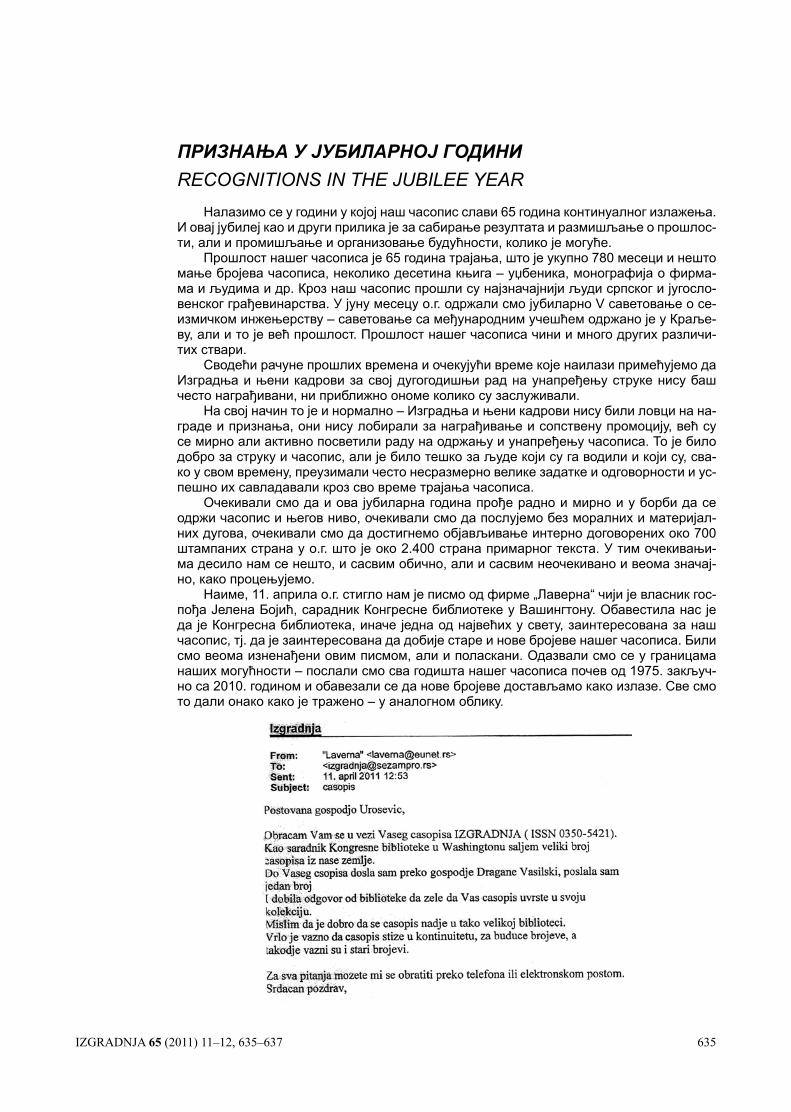
Наиме, 11. априла о.г. стигло нам је писмо од фирме „Лаверна“ чији је власник гос-пођа Јелена Бојић, сарадник Конгресне библиотеке у Вашингтону. Обавестила нас је да је Конгресна библиотека, иначе једна од највећих у свету, заинтересована за наш часопис, тј. да је заинтересована да добије старе и нове бројеве нашег часописа. Били смо веома изненађени овим писмом, али и поласкани. Одазвали смо се у границама наших могућности – послали смо сва годишта нашег часописа почев од 1975. закључ-но са 2010. годином и обавезали се да нове бројеве достављамо како излазе. Све смо то дали онако како је тражено – у аналогном облику.
IZGRADNJA 65 (2011) 11–12, 635–637 635
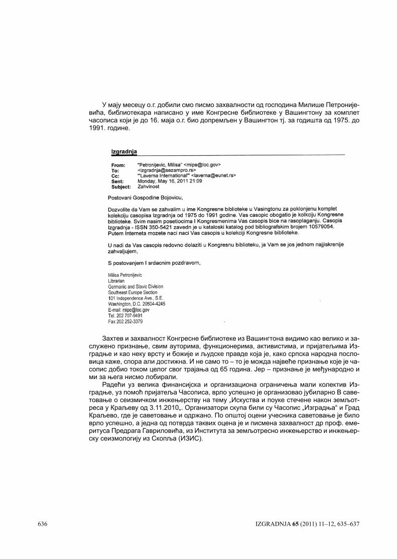
У мају месецу о.г. добили смо писмо захвалности од господина Милише Петроније-вића, библиотекара написано у име Конгресне библиотеке у Вашингтону за комплет часописа који је до 16. маја о.г. био допремљен у Вашингтон тј. за годишта од 1975. до 1991. године.
Захтев и захвалност Конгресне библиотеке из Вашингтона видимо као велико и за-служено признање, свим ауторима, функционерима, активистима, и пријатељима Из-градње и као неку врсту и божије и људске правде која је, како српска народна посло-вица каже, спора али достижна. И не само то – то је можда највеће признање које је ча-сопис добио током целог свог трајања од 65 година. Јер – признање је међународно и ми за њега нисмо лобирали.
Радећи уз велика финансијска и организациона ограничења мали колектив Из-градње, уз помоћ пријатеља Часописа, врло успешно је организовао јубиларно В саве-товање о сеизмичком инжењерству на тему „Искуства и поуке стечене након земљот-реса у Краљеву од 3.11.2010„. Организатори скупа били су Часопис „Изградња“ и Град Краљево, где је саветовање и одржано. По општој оцени учесника саветовање је било врло успешно, а једна од потврда таквих оцена је и писмена захвалност др проф. еме-ритуса Предрага Гавриловића, из Института за земљотресно инжењерство и инжењер-ску сеизмологију из Скопља (ИЗИС).
636 IZGRADNJA 65 (2011) 11–12, 635–637
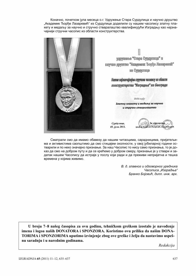
Коначно, почетком јула месеца о.г. Удружење Стара Сурдулица и научно друштво „Академик Ђорђе Лазаревић“ из Сурдулице доделили су нашем часопису златну пла-кету и медаљу за научно и стручно стваралаштво квалификујући Изградњу као најзна-чајнији стручни часопис из области конструктерства.
Сматрали смо да имамо обавезу да нашим читаоцима, сарадницима, пријатељи-ма и активистима саопштимо да смо стицајем околности, у овој јубиларној години ос-тварили и по неко значајно признање. За наш Часопис то нису само признања, то је до-каз да смо на добром путу и да се крећемо у добром смеру, признање је у ствари и за-датак нашем Часопису да истраје у послу који ради и да преживи непријатна и тешка времена у којима живимо.
В. д. главног и одговорног уредника Часописа „Изградња“
Бранко Бојовић, дипл. инж. арх.
IZGRADNJA 65 (2011) 11–12, 635–637 637
U broju 7–8 našeg časopisa za ovu godinu, tehničkom greškom izostalo je navođenje imena i logoa naših DONATORA i SPONZORA. Koristimo ovu priliku da našim DONA-TORIMA i SPONZORIMA uputimo izvinjenje zbog ove greške i želju da nastavimo uspeš-nu saradnju i u narednim godinama.
Redakcija
Свим чиаоцима, сараницима и ословним арнерима, срећну и усешну
Нову 2012. оину
жели Реакција „Израње“
IZGRADNJA 65 (2011) 11–12, 639–650 639
При разматрању физичких и механичких карак-теристика алуминијумских легура, најприкладније је вршити поређење са конструкционим или нерђајућим челицима, као материјалима који представљају нај-већу „конкуренцију“ алуминијуму. Алуминијумске легуре представљају врло широку фамилију прилич-но разноврсних материјала, па је тешко говорити о генералним сличностима алуминијума и других ме-тала. Стога су алуминијумске легуре, у зависности од легирајућих елемената и стања производа, подељене у серије. Усвојен је нумерички систем означавања помоћу четвороцифрених арапских бројева од којих први дефинише серију, према преовлађујућим леги-рајућим елементима:
Серија 1XXX У овој групи су легуре које имају најмање 99% чистог алуминију-ма.
Серија 2XXX Легуре алуминијума са бакром, магнезијумом и силицијумом (Al-Cu, Al-Cu-Mg, Al-Cu-Si).
Серија 3XXX Легуре алуминијума са манга-ном (Al-Mn).
1. УВОД
Алуминијум је трећи најраспрострањенији еле-мент у земљиној кори после кисеоника и силицијума са заступљеношћу од чак 8,07%. Чист алуминијум је мекан и ограничене чврстоће, али у комбинацији са легирајућим елементима као што су бакар, манган, силицијум, магнезијум и цинк, добијају се каракте-ристике које алуминијумске легуре чине погодним за примену у многим гранама индустрије. Своју приме-ну налази и у грађевинарству као материјал који је, захваљујући филму оксида, врло отпоран на дејство корозије. У чистом стању алуминијум се лако обли-кује, а помешан са малим количинама других метала у виду легура, може да достигне чврстоћу челика са само трећином његове тежине. Поред легирања, ка-рактеристике алуминијума могу се знатно побољша-ти и термичком обрадом (жарењем, каљењем, дозре-вањем и обрадом у хладном стању).
САВРЕМЕНИ КОНЦЕПТ ПРОЈЕКТОВАЊА КОНСТРУКЦИЈА ОД АЛУМИНИЈУМСКИХ ЛЕГУРА ПРЕМА ЕВРОКОДУ 9THE CONTEMPORARY DESIGN CONCEPT OF ALUMINUM ALLOYS STRUCTURES ACCORDING TO EUROCODE 9
UDK: 624.014.7(083.133) Pregledni rad
Проф. др Златко МАРКОВИћ, дипл. грађ. инж. Јелена ДРАГАш, дипл. грађ. инж.
РЕЗИМЕУ овом раду су изложени основни принципи пројектовања конструкција од алуми-
нијумских легура према најновијем европском стандарду ЕN1999-1-1/2007: Прорачун алуминијумских конструкција. Поред анализе прорачуна носивости и стабилности алу-минијумских конструкција у раду је дат и приказ карактеристика алуминијума као конс-труктивног материјала, његових предности и мана, као и могућа примена у грађевинарс-тву. Принципи прорачуна носивости илустровани су и карактеристичним нумеричким примерима.
Кључне речи: aлуминијум, kонструкције, прорачун, зона утицаја топлоте, Еврокод 9
SUMMARYThis paper provides an overview on basic principles of design Al-alloy structures based
on the latest European standard ЕN1999-1-1/2007: Design of aluminium structures. Along with the design of resistance and stability of aluminium structures, presented is an overview of the characteristics of aluminium as a structural material, its advantages and disadvantages, and its possible application in civil engineering. The principles of design of cross sections resistance are illustrated in characteristic numeric examples.
Key words: aluminium, structures, design, heat affected zone, Eurocode 9
Адреса аутора: Грађевински факултет Универзитета у Београду, Институт за материјале и конструкције, 11000 Београд, Булевар краља Александра 73E-mail: [email protected]: [email protected]
640 IZGRADNJA 65 (2011) 11–12, 639–650
Серија 4XXX Легуре алуминијума са сили-цијумом (Al-Si).
Серија 5XXX Легуре алуминијума са магне-зијумом (Al-Mg).
Серија 6XXX Легуре алуминијума са сили-цијумом и магнезијумом (Al-Si-Mg).
Серија 7XXX Легуре алуминијума са цинком и магнезијумом (Al-Zn-Mg).
Серија 8XXX Легуре алуминијума са осталим легирајућим елементима.
Остали бројеви у основној ознаци (ХХХ) под-робније описују поједина својства конкретне Ал-ле-гуре. Поред основне ознаке Ал-легуре могу да имају и додатне ознаке које описују стање, односно начин термичке обраде. Наиме, производ од исте легуре до-бијен истим основним производним процесом, има битно различите употребне особине у зависности од начина термичке обраде производа, односно стања. У табели 1 приказана је веза између додатних ознака и начина термичке обраде, односно стања Ал-легуре.
У табели 2 је дат упоредни приказ основних својстава алуминијумске легуре серије 6061-Т6, конструкционих челика и једног нерђајућег челика.
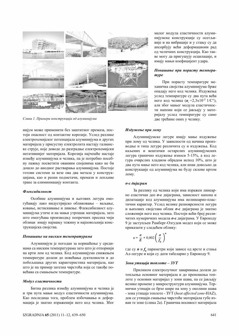
Бројне предности алуминијума намећу га као одлично решење за многе конструкције као што су: системи кровова средњег и великог распона код којих смањење тежине игра велику улогу, конструк-ције јавних, стамбених и других објеката са изло-женом конструкцијом који се налазе у приморским крајевима, конструкције које се налазе у агресивним срединама (кровови базена, мостови, offshore конс-трукције...), конструкције са покретним деловима којима алуминијум као лак материјал омогућава знатно већу економичност, објекти за складиштење и транспорт материја које агресивно делују на че-лик (резервоари, цевоводи...), конструкције високог степена радионичке обраде, које обједињују носећу функцију и функцију облоге, конструкције које је јако тешко одржавати (светионике, далеководе, но-саче саобраћајних знакова...), конструкције у преде-лима који су доста удаљени од места производње па
Табела 1. Стање производа од алуминијумских легура - додатне ознаке
Ознака Назив стања Опис стања
0 Меко Постигнуто рекристализационим жарењем про-извода добијених пластичном обрадом у хладном стању
Т3
Термички очврсло са природним ста-рењем и хладном обрадом
Постигнуто дозревањем на собној температури и обрадом у хладном стању
Т4Термички очврсло са природним ста-рењем
Постигнуто дозревањем на собној температури
Т5 Стабилно Постигнуто жарењем производа примарне про-изводње на температурама испод доње границе рекристализације
Т6Термички очврсло са вештачким ста-рењем
Постигнуто растворним жарењем и термичим очвршћавањем при повишеним температурама (вештачко старење) производа од легура погод-них за термичко очвршћавање
Т8
Термички очврсло са вештачким ста-рењем и хладном обрадом
Постигнуто вештачким старењем производа од легура погодних за термичко очвршћавање и об-радом у хладном стању
Табела 2. Упоредни приказ својстава алуминијума, челика и нерђајућег челика
Карактеристике материјала
Алуминијум6061-Т6
ЧеликS235-S355
Инокс1.4301
Обрадљивост врло добра недовољна ограничена
Заварљивост слаба, редукција чврстоће
добра, нема редукције добра
Отпорност на корозију добра слаба врло добраГраница развлачења - fy 240 MPa 235-355 MPa 210 MPaСпецифична тежина 26,5 kN/m3 78,5 kN/m3 77 kN/m3
Модул еластичности-Е 70 GPa 210 GPa 200GPaИздужење при лому 8%-10% 20% 45%Однос чврстоћа/тежина 9,0 3,0-4,5 2,7
трошкови транспорта представљају битну ставку (далеководи), монтаж-но демонтажне конструкције разли-чите намене, конструкције које се граде у тешко приступачним преде-лима (понтонски мостови, помоћни мостови, скеле). Такође се користи за постојеће конструкције код којих је због планираног повећања опте-рећења предвиђена замена старих елемената елементима мање тежине, као и за конструкције у пределима са веома ниским температурама у који-ма је употреба челика немогућа. На слици 1 су приказани неки примери објеката од алуминијума.
2. СПЕЦИФИЧНОСТИ АЛУМИ-НИЈУМСКИХ ЛЕГУРА
Специфична тежина
Алуминијумске легуре имају тежину приближно три пута мању од челика, што омогућава израду лакших конструкција, као и лакши и јефтинији транспорт и монтажу.
Отпорност на дејство корозије
Природни слој алуминијум-оксида обезбеђује високо ефикас-ну препреку зубу времена, утицају ниске температуре, влаге и хемијски агресивним супстанцама. Зa разлику од челика који годишње губи око 80 g/m2, алуминијум губи само 2-4 g/m2 услед дејства корозије. Иако се, због добре отпорности на корозију алуми-
IZGRADNJA 65 (2011) 11–12, 639–650 641
нијум може применити без заштитног премаза, пос-тоји опасност од контактне корозије. Услед разлике електрохемијског потенцијала алуминијума и других материјала у присуству електролита настају галванс-ке струје, које доводе до разградње електрохемијски негативнијег материјала. Корозија најчешће настаје између алуминијума и челика, па је потребно посеб-ну пажњу посветити оваквим спојевима како не би дошло до анодног растварања алуминијума. Постоје готови системи за везе ова два метала у конструк-цијама, као и разни подметачи, премази и лепљиве траке за елиминиацију контакта.
Флексибилност
Особине алуминијума и његових легура омо-гућавају лако индустријско обликовање – ваљање, ковање, истискивање и ливење. Флексибилност алу-минијума утиче и на мањи утрошак материјала, зато што омогућава производњу попречних пресека чији облици имају најмању тежину и најповољнија конс-трукцијска својства.
Понашање на ниским темепратурама
Алуминијум је погодан за коришћење у среди-нама са ниским температурама зато што је отпорнији на крти лом од челика. Код алуминијума снижењем температуре долази до повећања дуктилности и до побољшања других карактеристика материјала, као што је на пример затезна чврстоћа која се такође по-већава са смањењем температуре.
Модул еластичности
Битна разлика између алуминијума и челика је и три пута мањи модул еластичности алуминијума. Као последица тога, проблем избочавања и дефор-мација је знатно израженији него код челика. Због
Издужење при лому
Алуминијумске легуре имају мање издужење при лому од челика. У зависности од начина произ-водње и типа легуре различита су и издужења. Код каљених и вештачки остарелих алуминијумских легура гранично издужење износи 5-15%, а код ле-гура очврслих хладном обрадом испод 10%, што је два пута мање него код челика, али ипак довољно да конструкције од алуминијума не буду склоне кртом лому.
σ-ε дијаграм
За разлику од челика који има изражен линеар-но еластичан део σ-ε дијаграма, зависност напона и дилатације код алуминијума има нелинеарно-плас-тични карактер. Услед велике разноврсности легура и њихових својстава облик σ-ε дијаграма је знатно сложенији него код челика. Постоји већи број разли-читих нумеричких модела σ-ε дијаграма. У Еврокоду 9 је заступљен Рамберг-Озгудов модел који се може приказати у следећем облику:
ε = σЕ
+ 0,002σf0
n
где су n и f0 параметри који зависе од врсте и стања Ал-легуре и који су дати табеларно у Еврокоду 9.
Зона утицаја топлоте – ЗУТ
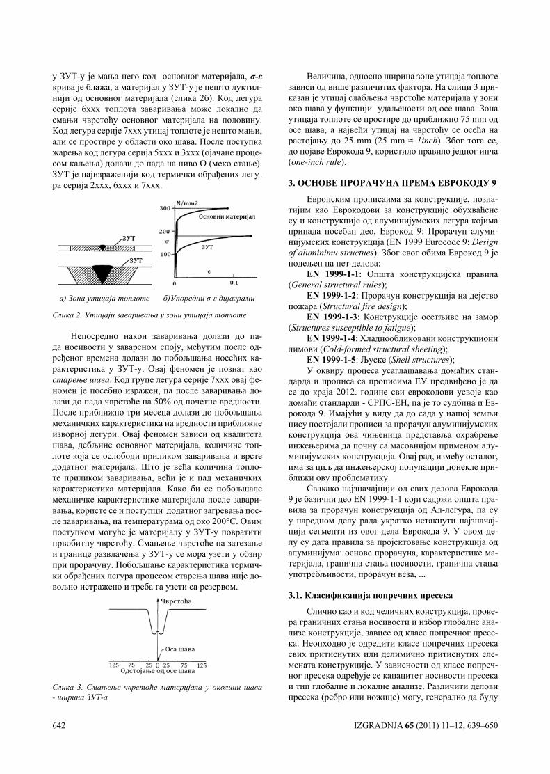
Приликом електролучног заваривања долази до топљења основног материјала и до преношења топ-лоте у основни материјал у зони шава, па се јављају велике промене у микроструктури алуминијума. Тер-мички утицаји се брзо шире на зону у околини шава - зона утицаја топлоте - ЗУТ (heat affected zone-HAZ), док се утицаји смањења чврстоће материјала губе из-ван те зоне (слика 2а). Гранична носивост материјала
Слика 1. Примери конструкција од алуминијума
малог модула еластичности алуми-нијумске конструкције су осетљи-вије и на вибрације и у стању су да апсорбују већи деформациони рад од челичних конструкција. Као так-ве могу да пригушују осцилације, и имају мањи коефицијент удара.
Понашање при порасту темпера-туре
При порасту темпаратуре ме-ханичка својства алуминијума брже опадају него код челика. Издужења услед темпаратуре су два пута већа него код челика (αt =2,3х10-5 1/С°), али због мањег модула еластичнос-ти напони који се јављају у мате-ријалу услед температуре су само две трећине оних у челику.
642 IZGRADNJA 65 (2011) 11–12, 639–650
у ЗУТ-у је мања него код основног материјала, σ-ε крива је блажа, а материјал у ЗУТ-у је нешто дуктил-нији од основног материјала (слика 2б). Код легура серије 6xxx топлота заваривања може локално да смањи чврстоћу основног материјала на половину. Код легура серије 7xxx утицај топлоте је нешто мањи, али се простире у области око шава. После поступка жарења код легура серија 5xxx и 3xxx (ојачане проце-сом каљења) долази до пада на ниво О (меко стање). ЗУТ је најизраженији код термички обрађених легу-ра серија 2xxx, 6xxx и 7xxx.
а) Зона утицаја топлоте б)Упоредни σ-ε дијаграми
Слика 2. Утицаји заваривања у зони утицаја топлоте
Непосредно након заваривања долази до па-да носивости у завареном споју, међутим после од-ређеног времена долази до побољшања носећих ка-рактеристика у ЗУТ-у. Овај феномен је познат као старење шава. Код групе легура серије 7xxx овај фе-номен је посебно изражен, па после заваривања до-лази до пада чврстоће на 50% од почетне вредности. После приближно три месеца долази до побољшања механичких карактеристика на вредности приближне изворној легури. Овај феномен зависи од квалитета шава, дебљине основног материјала, количине топ-лоте која се ослободи приликом заваривања и врсте додатног материјала. Што је већа количина топло-те приликом заваривања, већи је и пад механичких карактеристика материјала. Како би се побољшале механичке карактеристике материјала после завари-вања, користе се и поступци додатног загревања пос-ле заваривања, на температурама од око 200°C. Овим поступком могуће је материјалу у ЗУТ-у повратити првобитну чврстоћу. Смањење чврстоће на затезање и границе развлачења у ЗУТ-у се мора узети у обзир при прорачуну. Побољшање карактеристика термич-ки обрађених легура процесом старења шава није до-вољно истражено и треба га узети са резервом.
Слика 3. Смањење чврстоће материјала у околини шава - ширина ЗУТ-а
Величина, односно ширина зоне утицаја топлоте зависи од више различитих фактора. На слици 3 при-казан је утицај слабљења чврстоће материјала у зони око шава у функцији удаљености од осе шава. Зона утицаја топлоте се простире до приближно 75 mm од осе шава, а највећи утицај на чврстоћу се осећа на растојању до 25 mm (25 mm ≅ 1inch). Због тога се, до појаве Еврокода 9, користило правило једног инча (one-inch rule).
3. ОСНОВЕ ПРОРАЧУНА ПРЕМА ЕВРОКОДУ 9
Европским прописаима за конструкције, позна-тијим као Еврокодови за конструкције обухваћене су и конструкције од алуминијумских легура којима припада посебан део, Еврокод 9: Прорачун алуми-нијумских конструкција (EN 1999 Eurocode 9: Design of aluminimu structues). Због свог обима Еврокод 9 је подељен на пет делова:
EN 1999-1-1: Општа конструкцијска правила (General structural rules);
EN 1999-1-2: Прорачун конструкција на дејство пожара (Structural fire design);
EN 1999-1-3: Конструкције осетљиве на замор (Structures susceptible to fatigue);
EN 1999-1-4: Хладнообликовани конструкциони лимови (Cold-formed structural sheeting);
EN 1999-1-5: Љуске (Shell structures);У оквиру процеса усаглашавања домаћих стан-
дарда и прописа са прописима ЕУ предвиђено је да се до краја 2012. године сви еврокодови усвоје као домаћи стандарди - СРПС-ЕН, па је то судбина и Ев-рокода 9. Имајући у виду да до сада у нашој земљи нису постојали прописи за прорачун алуминијумских конструкција ова чињеница представља охрабрење инжењерима да почну са масовнијом применом алу-минијумских конструкција. Овај рад, између осталог, има за циљ да инжењерској популацији донекле при-ближи ову проблематику.
Свакако најзначајнији од свих делова Еврокода 9 је базични део EN 1999-1-1 који садржи општа пра-вила за прорачун конструкција од Ал-легура, па су у наредном делу рада укратко истакнути најзначај-нији сегменти из овог дела Еврокода 9. У овом де-лу су дата правила за пројектовање конструкција од алуминијума: основе прорачуна, карактеристике ма-теријала, гранична стања носивости, гранична стања употребљивости, прорачун веза, ...
3.1. Класификација попречних пресека
Слично као и код челичних конструкција, прове-ра граничних стања носивости и избор глобалне ана-лизе конструкције, зависе од класе попречног пресе-ка. Неопходно је одредити класе попречних пресека свих притиснутих или делимично притиснутих еле-мената конструкције. У зависности од класе попреч-ног пресека одређује се капацитет носивости пресека и тип глобалне и локалне анализе. Различити делови пресека (ребро или ножице) могу, генерално да буду
IZGRADNJA 65 (2011) 11–12, 639–650 643
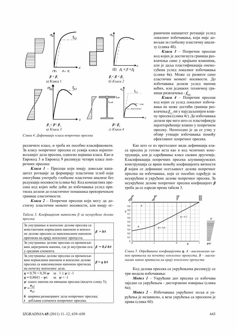
различите класе, и треба их посебно класификовати. За класу попречног пресека се усваја класа најнепо-вољнијег дела пресека, односно највиша класа. Као и Еврокод 3 и Еврокод 9 разликује четири класе поп-речних пресека:
Класа 1 – Пресеци који имају довољан капа-цитет ротације да формирају пластични зглоб који омогућава употребу глобалне пластичне анализе без редукције носивости (слика 4а). Код компактних пре-сека код којих неће доћи до избочавања услед при-тиска долази до пластичног понашања прекорачењем границе еластичности.
Класа 2 – Попречни пресеци који могу да до-стигну пластични момент носивости, али имају ог-
Као што се из претходног види дефиниција кла-са пресека је готово иста као и код челичних конс-трукција, али је одређивање класе сасвим другачије. Класификација попречних пресека алуминијумских конструкција се врши помоћу коефицијента виткости β којим се дефинише осетљивост делова попречног пресека на избочавање, који се посебно одређује за неукрућене и укрућене делове попречног пресека. За неукрућене делове попречног пресека коефицијент β треба да се одреди према табели 3.
Слика 5. Одређивање коефицијента η. А –маскималан на-пон притиска на почетку конзолног препуста, В – маски-малан напон притиска на крају конзолног препуста
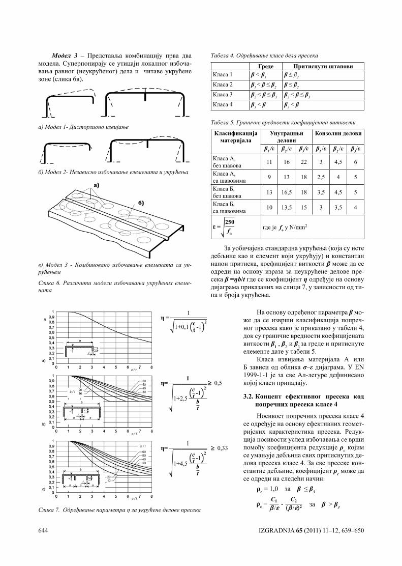
Код делова пресека са укрућењима разликују се три модела избочавања:
Модел 1 – Укрућени део пресека се избочава заједно са укрућењем - дисторзионо извијање (слика 6а);
Модел 2 – Избочавање укрућеног поља и ук-рућења је независно, а веза укрућења са пресеком је права (слика 6б).
β < β1 β1< β < β2
а) Класа 1 б) Класа 2
β 2< β< β3 β< β4
в) Класа 3 г) Класа 4
Слика 4. Дефиниције класа попречних пресека
раничени капацитет ротације услед локалног избочавања, који није до-вољан за глобалну пластичну анали-зу (слика 4б).
Класа 3 – Попречни пресеци код којих је достигнута граница раз-влачења само у крајњим влакнима, али је даља пластификација онемо-гућена услед локалног избочавања (слика 4в). Може се развити само еластични момент носивости. До избочавања долази услед напона већих, или једнаких техничкој гра-ници развлачења - f0,2.
Класа 4 – Попречни пресеци код којих се услед локалног избоча-вања не може достићи граница раз-влачења f0,2 ни у најудаљенијем влак-ну пресека (слика 4г). До избочавања долази пре него што се пластификује најоптерећеније влакно у попречном пресеку. Неопходно је да се узму у обзир утицаји избочавања помоћу ефективног попречног пресека.
Табела 3. Kоефицијент виткости β за неукрућене делове пресека
За унутрашње и конзолне делове пресека са константним нормалним напоном и конзол-не делове пресека са максималним напоном притиска на крају конзолног препуста.
β = b/t
За унутрашње делове пресека са променљи-вим дијаграмом напона, где је неутрална оса у средини елемента.
β = 0,4 b/t
За унутрашње делове пресека са променљи-вим нормалним напоном и конзолне делове пресека са максималним напоном притиска на почетку конзолног дела.
β = η b/t
η = 0,70 + 0,30 ψ за 1 ≥ ψ ≥ -1η = 0,80/(1 – ψ) за ψ<-1ψ однос напона на ивицама пресека (видети слику 5);ψ =
σx2σx1
b ширина разматраног дела попречног пресека;t дебљина елемента попречног пресека.
644 IZGRADNJA 65 (2011) 11–12, 639–650
Модел 3 – Представља комбинацију прва два модела. Суперпонирају се утицаји локалног избоча-вања равног (неукрућеног) дела и читаве укрућене зоне (слика 6в).
а) Модел 1- Дисторзионо извијање
б) Модел 2- Независно избочавање елемената и укрућења
в) Модел 3 - Комбиновано избочавање елемената са ук-рућењем
Слика 6. Различити модели избочавања укрућених елеме-ната
Табела 4. Одређивање класе дела пресека
Греде Притиснути штаповиКласа 1 β < β1 β ≤ β2
Класа 2 β1 < β ≤ β2 β ≤ β2
Класа 3 β2 < β ≤ β3 β2 < β ≤ β3
Класа 4 β3 < β β3 < β
Табела 5. Граничне вредности коефицијента виткости
Класификацијаматеријала
Унутрашњи делови
Конзолни делови
β1 /ε β2 /ε β3/ε β1 /ε β2 /ε β3/εКласа А, без шавова 11 16 22 3 4,5 6
Класа А, са шавовима 9 13 18 2,5 4 5
Класа Б, без шавова 13 16,5 18 3,5 4,5 5
Класа Б, са шавовима 10 13,5 15 3 3,5 4
ε =250fо
где је fо у N/mm2
За уобичајена стандардна укрућења (која су исте дебљине као и елемент који укрућују) и константан напон притиска, коефицијент виткости β може да се одреди на основу израза за неукрућене делове пре-сека β=ηb/t где се коефицијент η одређује на основу дијаграма приказаних на слици 7, у зависности од ти-па и броја укрућења.
η =1+
1
0,1 ct -1
2
η=
1+2
1
2,5ct -1
2
bt
≥≥ 0,5
η=
1+4
1
4,5ct -1
2
bt
≥ 0,33
Слика 7. Одређивање параметра η за укрућене делове пресека
На основу одређеног параметра β мо-же да се изврши класификација попреч-ног пресека како је приказано у табели 4, док су граничне вредности коефицијената виткости β1 , β2 и β3 за греде и притиснуте елементе дате у табели 5.
Класа извијања материјала А или Б зависи од облика σ–ε дијаграма. У EN 1999-1-1 је за све Ал-легуре дефинисано којој класи припадају.
3.2. Концепт ефективног пресека код попречних пресека класе 4
Носивост попречних пресека класе 4 се одређује на основу ефективних геомет-ријских карактеристика пресека. Редук-ција носивости услед избочавања се врши помоћу коефицијента редукције ρс којим се умањује дебљина свих притиснутих де-лова пресека класе 4. За све пресеке кон-стантне дебљине, коефицијент ρс може да се одреди на следећи начин:
ρс = 1,0 за β ≤ β3
ρс = С1
β /ε - С2
β /ε 2 за β > β3
IZGRADNJA 65 (2011) 11–12, 639–650 645
где су коефицијенти С1 и С2 дати у табели 6.
Табела 6. Вредности коефицијената С1 и С2
Класификацијаматеријала
Унутрашњи делови
Конзолни делови
С1 С2 С1 С2
Класа А, без шавова 32 220 10 24Класа А, са шавовима 29 198 9 20Класа Б, без шавова 29 198 9 20Класа Б, са шавовима 25 150 8 16
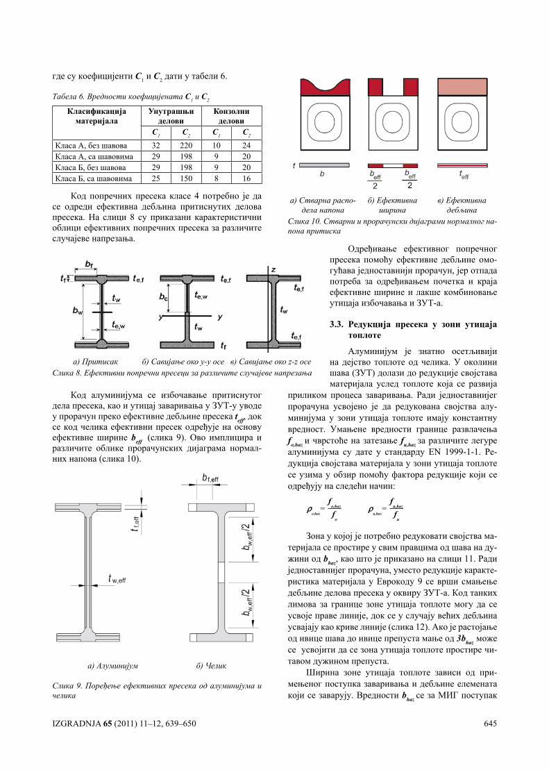
Код попречних пресека класе 4 потребно је да се одреди ефективна дебљина притиснутих делова пресека. На слици 8 су приказани карактеристични облици ефективних попречних пресека за различите случајеве напрезања.
а) Стварна распо-дела напона
б) Ефективна ширина
в) Ефективна дебљина
Слика 10. Стварни и прорачунски дијаграми нормалног на-пона притиска
а) Притисак б) Савијање око y-y осе в) Савијање око z-z осеСлика 8. Ефективни попречни пресеци за различите случајеве напрезања
Код алуминијума се избочавање притиснутог дела пресека, као и утицај заваривања у ЗУТ-у уводе у прорачун преко ефективне дебљине пресека teff, док се код челика ефективни пресек одређује на основу ефективне ширине beff (слика 9). Ово имплицира и различите облике прорачунских дијаграма нормал-них напона (слика 10).
а) Алуминијум б) Челик
Слика 9. Поређење ефективних пресека од алуминијума и челика
приликом процеса заваривања. Ради једноставнијег прорачуна усвојено је да редукована својства алу-минијума у зони утицаја топлоте имају константну вредност. Умањене вредности границе развлачења fo,haz и чврстоће на затезање fu,haz за различите легуре алуминијума су дате у стандарду EN 1999-1-1. Ре-дукција својстава материјала у зони утицаја топлоте се узима у обзир помоћу фактора редукције који се одређују на следећи начин:
ρo,haz
= f
o,haz
fo
ρu,haz
=f
u,haz
fu
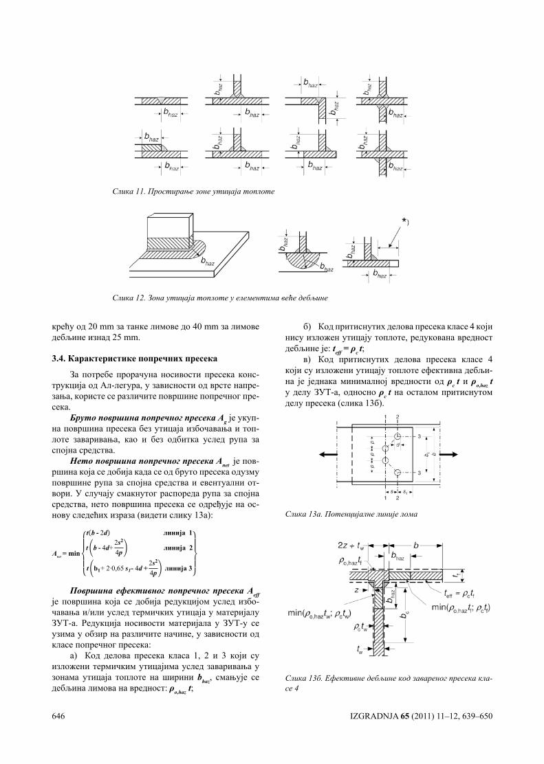
Зона у којој је потребно редуковати својства ма-теријала се простире у свим правцима од шава на ду-жини од bhaz, као што је приказано на слици 11. Ради једноставнијег прорачуна, уместо редукције каракте-ристика материјала у Еврокоду 9 се врши смањење дебљине делова пресека у оквиру ЗУТ-а. Код танких лимова за границе зоне утицаја топлоте могу да се усвоје праве линије, док се у случају већих дебљина усвајају као криве линије (слика 12). Ако је растојање од ивице шава до ивице препуста мање од 3bhaz може се усвојити да се зона утицаја топлоте простире чи-тавом дужином препуста.
Ширина зоне утицаја топлоте зависи од при-мењеног поступка заваривања и дебљине елемената који се заварују. Вредности bhaz се за МИГ поступак
Одређивање ефективног попречног пресека помоћу ефективне дебљине омо-гућава једноставнији прорачун, јер отпада потреба за одређивањем почетка и краја ефективне ширине и лакше комбиновање утицаја избочавања и ЗУТ-а.
3.3. Редукција пресека у зони утицаја топлоте
Алуминијум је знатно осетљивији на дејство топлоте од челика. У околини шава (ЗУТ) долази до редукције својстава материјала услед топлоте која се развија
646 IZGRADNJA 65 (2011) 11–12, 639–650
крећу од 20 mm за танке лимове до 40 mm за лимове дебљине изнад 25 mm.
3.4. Карактеристике попречних пресека
За потребе прорачуна носивости пресека конс-трукција од Ал-легура, у зависности од врсте напре-зања, користе се различите површине попречног пре-сека.
Бруто површина попречног пресека Аg је укуп-на површина пресека без утицаја избочавања и топ-лоте заваривања, као и без одбитка услед рупа за спојна средства.
Нето површина попречног пресека Аnet je пов-ршина која се добија када се од бруто пресека одузму површине рупа за спојна средства и евентуални от-вори. У случају смакнутог распореда рупа за спојна средства, нето површина пресека се одређује на ос-нову следећих израза (видети слику 13а):
Anet = min
t b - 2d линија 1
t b - 4d+2s2
4p линија 2
t b1+ 2·0,65 s1- 4d +2s2
4pлинија 3
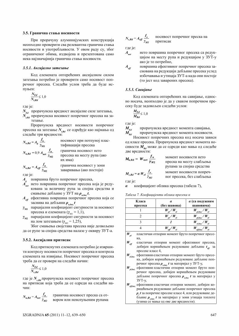
Површина ефективног попречног пресека Аеffје површина која се добија редукцијом услед избо-чавања и/или услед термичких утицаја у материјалу ЗУТ-а. Редукција носивости материјала у ЗУТ-у се узима у обзир на различите начине, у зависности од класе попречног пресека:
а) Код делова пресека класа 1, 2 и 3 који су изложени термичким утицајима услед заваривања у зонама утицаја топлоте на ширини bhaz, смањује се дебљина лимова на вредност: ρo,haz t;
б) Код притиснутих делова пресека класе 4 који нису изложен утицају топлоте, редукована вредност дебљине је: teff = ρс t;
в) Код притиснутих делова пресека класе 4 који су изложени утицају топлоте ефективна дебљи-на је једнака минималној вредности од ρс t и ρo,haz t у делу ЗУТ-а, односно ρс t на осталом притиснутом делу пресека (слика 13б).
Слика 13а. Потенцијалне линије лома
Слика 13б. Ефективне дебљине код завареног пресека кла-се 4
Слика 11. Простирање зоне утицаја топлоте
Слика 12. Зона утицаја топлоте у елементима веће дебљине
IZGRADNJA 65 (2011) 11–12, 639–650 647
3.5. Гранична стања носивости
При прорачуну алуминијумских конструкција неопходно проверити сва релевантна гранична стања носивости и употребљивости. У овом раду су, због ограниченог обима, издвојена и презентована само нека најзначајнија гранична стања носивости.
3.5.1. Аксијално затезање
Код елемената оптерећених аксијалном силом затезања потребно је проверити само носивост поп-речног пресека. Следећи услов треба да буде ис-пуњен:
NEd
Nt,Rd≤ 1,0
где је:NEd прорачунска вредност аксијалне силе затезања,Nt,Rd прорачунска носивост попречног пресека на за-
тезање.Прорачунска вредност носивости попречног
пресека на затезање Nt,Rd се одређује као најмања од следеће три вредности:
No,Rd = Agfo
γM1
носивост при потпуној плас-тификацији пресека
Nu,Rd = 0,9 Anetfu
γM2
гранична носивост нето пресека на месту рупа (ако их има)
No,Rd = Aefffu
γM2
гранична носивост у зони заваривања (ако постоји)
где је:Ag површина бруто попречног пресека,Anet нето површина попречног пресека која је реду-
кована за величину рупа за спојна средства и смањење дебљине у ЗУТ на ρu,haz t,
Aeff ефективна површина попречног пресека која се заснива на дебљини ρu,haz t,
γM1 парцијални коефицијент сигурности за носивост пресека и елемената (γM1= 1,1),
γM2 парцијални коефицијент сигурности за носивост на лом затезањем (γM2= 1,25),Због смањења својстава пресека није дозвољено
да се рупе за спојна средства налазе у оквиру ЗУТ-а.
3.5.2. Аксијални притисак
Код притиснутих елемената потребно је изврши-ти контролу носивости попречног пресека и контрола елемената на извијање. Носивост попречног пресека треба да се провери на следећи начин:
NEd
Nс,Rd≤ 1,0
где јеNс,Rdпрорачунска носивост попречног пресека на притисак која треба да се одреди на следећи на-чин:
Nu,Rd = Anetfu
γM2
гранична носивост преска са от-вором или неиспуњеним рупама
Nс,Rd = Aefffо
γM1
носивост попречног преска на притисак
где је:Anet нето површина попречног пресека са редук-
цијом на месту рупа и редукцијом у ЗУТ-у ако је то потребно,
Aeff површина ефективног попречног пресека за-снована на редукцији дебљине пресека услед избочавања и утицаја ЗУТ-а када они постоје (то јест код заварених пресека).
3.5.3. Савијање
Код елемената оптерећених на савијање, однос-но носача, неопходно је да у сваком попречном пре-секу буде задовољен следећи услов:
МEd
МRd≤ 1,0
где је:МEd прорачунска вредност момента савијања,МRd прорачунска вредност момента носивости.
Носивост попречних пресека кoд носача зависи од класе пресека. Прорачунска вредност момента но-сивости МRd може да се одреди као мања од следеће две вредности:
момент носивости нето преска на месту слабљења рупама за спојна средства
Мс,Rd = α Welfо
γM1
момент носивости попреч-ног пресека, без слабљења
где је:α коефицијент облика пресека (табела 7),
Taбела 7. Коефицијенти облика пресека α
Класа пресека
α(без шавова)
α (са подужним шавовима)
1 Wpl / Wel Wpl,haz / Wel
2 Wpl / Wel Wpl,haz / Wel
3 1 Wеl,haz / Wel
4 Weff / Wel Weff,haz / Wel
Wpl пластичан отпорни момент бруто попречног пресе-ка,
Weff еластичан отпорни момент ефективног пресека, добијен коришћењем редуковане дебљине teff за пресеке класе 4,
Wel,haz ефективни еластичан отпорни момент бруто пресе-ка, добијен коришћењем редуковане дебљине поп-речног пресека ρo,haz t за материјал у ЗУТ-у,
Wpl,haz ефективни пластични отпорни момент бруто поп-речног пресека, добијен коришћењем редуковане дебљине попречног пресека ρo,haz t за материјал у ЗУТ-у,
Weff,haz ефективни еластичан отпорни момент, добијен ко-ришћењем редуковане дебљине попречног пресека ρс t за попречне пресеке класе 4, или редуковане де-бљине ρo,haz t за материјал у зони утицаја топлоте (узима се мања од ове две вредности).
648 IZGRADNJA 65 (2011) 11–12, 639–650
Wel еластични отпорни момент бруто попречног пресека,
Wnet еластични отпорни момент нето попречног пре-сека.Услед дејства момента савијања код носача који
нису бочно придржани може да дође до бочно-торзи-оног извијања, па је потребно је проверити и ово гра-нично стање. У Еврокоду 9 су дата детаљна правила за прорачун носивости елемената на бочно-торзионо из-вијање. У Анексу I ЕN1999-1-1 је дат поступак за про-рачун критичног момента бочно-торзионог извијања.
3.5.4. Смицање
Код елемената оптерећених на смицање потреб-но је задовољити следећи услов:
VEd
VRd ≤ 1,0
где је:VEd прорачунска вредност силе смицања,VRd прорачунска носивост пресека на смицање.
Прорачунска пластична носивост попречног пресека на смицање VRd може да се одреди на основу следећег израза:
VRd = Avfo
γM1√3
где је Av површина смицања која зависи од облика попречног пресека.
3.5.5. Носивост притиснутих елемената на из-вијање
Поред носивости попречног пресека код притис-нутих елемената је неопходна и контрола носивости елемента на извијање:
NEd
Nb,Rd≤ 1,0
где је Nb,Rd прорачунска носивост елемената на из-вијање која треба да се одреди на основу следећег израза:
Nb,Rd = κ χ Аеfffo
γM1
где је:χ коефицијент редукције за разматрани вид из-
вијања,κ фактор којим се узима у обзир слабљење услед за-
варивања, који је једнак јединици за пресеке који нису формирани заваривањем,
Аeff површина ефективног пресека (код пресека класе 1, 2 и 3 Аeff = А).
Коефицијент редукције за разматрани вид из-вијања χсе одређује на следећи начин:
χ = 1
φ + φ2-λ2 < 1,0
φ = 0,5 1+α λ-λ0 +λ
λ = Аeff fo
Ncr
где је:α коефицијент имперфекције који зависи од криве
извијања (слика 14),λ– релативна виткост на извијање,λ– 0 граница хоризонталног платоа криве извијања,Ncr еластична критична сила за релевантни вид из-
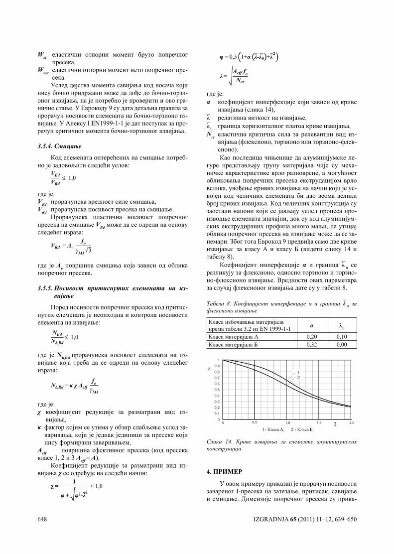
вијања (флексионо, торзионо или торзионо-флек-сионо).Као последица чињенице да алуминијумске ле-
гуре представљају групу материјала чије су меха-ничке карактеристике врло разноврсне, а могућност обликовања попречних пресека екструдацијом врло велика, увођење кривих извијања на начин који је ус-војен код челичних елемената би дао веома велики број кривих извијања. Код челичних конструкција су заостали напони који се јављају услед процеса про-изводње елемената значајни, док су код алуминијум-ских екструдираних профила много мањи, па утицај облика попречног пресека на извијање може да се за-немари. Због тога Еврокод 9 предвиђа само две криве извијања: за класу А и класу Б (видети слику 14 и табелу 8).
Коефицијент имперфекције α и граница λ– 0 се разликују за флексионо, односно торзионо и торзио-но-флексионо извијање. Вредности ових параметара за случај флексионог извијања дате су у табели 8.
Табела 8. Коефицијент имперфекције α и граница λ– 0 за флексионо извијање
Класа избочавања материјала према табели 3.2 из EN 1999-1-1 α λ0
Класа материјала А 0,20 0,10Класа материјала Б 0,32 0,00
Слика 14. Криве извијања за елементе алуминијумских конструкција
4. ПРИМЕР
У овом примеру приказан је прорачун носивости завареног I-пресека на затезање, притисак, савијање и смицање. Димензије попречног пресека су прика-
IZGRADNJA 65 (2011) 11–12, 639–650 649
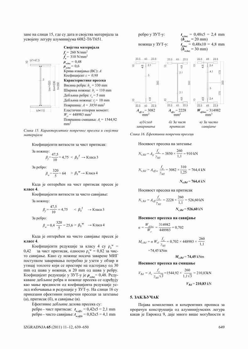
зане на слици 15, где су дата и својства материјала за усвојену легуру алуминијума 6082-Т6/Т651.
Својства материјалаfo = 260 N/mm2
fu = 310 N/mm2
ρo,haz = 0,48ρu,haz = 0,6Крива извијања (BC): AКоефицијент ε = 0,98Карактеристике пресекаВисина ребра: hw = 330 mmШирина ножице: bf = 110 mmДебљина ребра: tw = 5 mmДебљина ножице: tf = 10 mmПовршина: А = 3850 mm2
Еластични отпорни момeнт: Wel = 448983 mm3
Површина смицања: Av = 1544,92 mm2
Слика 15. Карактерситике попречног пресека и својства материјала
Коефицијенти виткости за чист притисак:За ножицу:
βf=47,510
= 4,75 < → Класа 3
За ребро:βw=
3205
= 64 > → Класа 4
Када је оптерећен на чист притисак пресек је класе 4.
Коефицијенти виткости за чисто савијање:За ножицу:
βf =47,510
= 4,75 < → Класа 3
За ребро:
βw= 0,4 3205
= 25,6 > → Класа 4
Када је оптерећен на чисто савијање пресек је класе 4.
Коефицијенти редукције за класу 4 су ρ0w =
0,42 за чист притисак, односно ρ0w = 0,82 за чис-
то савијање. Како су ножице носача заварене МИГ поступком заваривања потребно је узети у обзир и утицај топлоте који се простире на одстојању од 30 mm од шава у ножици, и 20 mm од шава у ребру. Коефицијент редукције у ЗУТ-у је ρo,haz= 0,48. Реду-каване дебљине ребра и ножице пресека се одређују као мање вредности од коефицијента редукције ус-лед избочавања и редукције у ЗУТ-у. На слици 16 су приказани ефективни попречни пресеци за затезање (а), притисак (б), и савијање (в).
Ефективне дебљине делова пресека су:ребро - чист притисак: tw,eff,c = 0,42х5 = 2,1 mmребро - чисто савијање: tw,eff,b = 0,82х5 = 4,1 mm
ребро у ЗУТ-у: tw,haz = 0,48х5 = 2,4 mm (bw,haz = 20 mm)
ножица у ЗУТ-у: tf,haz = 0,48х10 = 4,8 mm (bw,haz = 30 mm)
Аeff, w = 3082
mm2Аeff,c
= 2228 mm2
Weff,haz= 314982 mm3
а)Услед заваривања
б) За чист притисак
в) За чисто савијање
Слика 16. Ефективни попречни пресеци
Носивост пресека на затезање
No,Rd = Agfo
γM1= 3850 ×
2601,1
= 910 kN
No,Rd = 764,4 kN
No,Rd = Aeff,wfu
γM2= 3082 ×
3101,25
= 764,4 kN
Носивост пресека на притисак
Nс,Rd = Aefffo
γM1= 2228 ×
2601,1
= 526,60 kN
Nc,Rd = 526,60 kN
Носивост пресека на савијање
α =Weff,haz
Wel
=314982448983
= 0,702
Мс,Rd = α Welfо
γM1= 0,702 × 448983 ×
2601,1
=74,45 kNmMc,Rd = 74,45 kNm
Носивост пресека на смицање
VRd = Avfо
γM1√3=1544,92 ×
2601,1√3
= 210,83kN
VRd = 210,83 kN
5. ЗАКЉУЧАК
Појава комплетних и кохерентних прописа за прорачун конструкција од алуминијумских легура какав је Еврокод 9, даје много више могућности и
650 IZGRADNJA 65 (2011) 11–12, 639–650
слободе пројектантима металних конструкција, што индиректно може довести до веће примене алуми-нијумских конструкција Ипак, главне препреке за већу употребу алуминијума као конструктивног ма-теријала у грађевинарству остају његова висока цена и недовољно искуство у пројектовању и извођењу конструкција овог типа. Међутим, без обзира на не-сумњиво велике почетне трошкове алуминијумске конструкције, због незнатних трошкова одржавања и мање тежине у односу на челичну конструкције, у одређеним околностима избор алуминијума као ос-новног материјала за конструкцију може бити раци-оналан. Скора примена Еврокода 9 и у нашој земљи донеће многе бенефите у инжењерској пракси, јер ће коначно бити попуњена празнина у прописима који се баве овом проблематиком, али ће бити и отворена врата за знатно већу примену Ал-легура како у земљи тако и на иностраном тржишту. Што се самог прора-чуна тиче он се у великој мери ослања на принципе прорачуна челичних конструкција, али узимајући у обзир све специфичности алуминијумских легура које су презентоване у овом раду.
6. ЛИТЕРАТУРА
[1] EUROCODE 9: EN 1999-1-1: Design of aluminium structures, Part 1-1: General structural rules, Euro-pean Commitee for Standardization, 2007.
[2] Металне конструкције - Основе прорачу-на и конструисања, Драган Буђевац, Златко Марковић,Драгана Чукић, Драгослав Тошић, Београд, 2007.
[3] Аluminium structures, A Guide to Their Specifi-cations and Design, J. Randolp, Kissell, Robert L. Ferry, Second Edition, Canada, 2002.
[4] Aluminium Design and Construction, John Dwight, New York, 2002.
[5] Handbook of Aluminum - Volume 7, George E. Tot ten, D. Scott MacKenzie, Physical Metallurgy and Processes, New York, 2003.
[6] LIGHTWEIGHT STEEL AND ALUMINIUM STRUCTURES, P. Makelainen, R Hassinen, Fourth International Conference on Steel and Aluminium Structures, Espoo, Finland, 1999.
[7] Design of Aluminium Structures: Selection of Struc-tual Alloys, R.Gitter, Gesamtverband der Alumini-umindustrie e.V., Düsselldorf, Germany, February 2008.
[8] Aluminum Design Manual 2005, The Aluminum Association, Inc., Washington, DC, 2005.
[9] Strength and stability of aluminium members ac-cording to EN 1999-1-1–Eurocode 9, Torsten Höglund, Royal Institute of Technology, European Aluminium Association, Stockholm, 2008.
[10] Aluminium Alloy Structures, Federico M. Maz-zolani, Institute of Construction Technology Uni-versity of Naples, Italy, 1985.
[11] DESIGN CRITERIA FOR ALUMINIUM ALLOY STRUCTURES, Federico M. Mazzolani, Depart-ment of Structural Analysis and Design, Faculty of Engineering University of Naples University „Fed-erico II“, 2008.
[12] Understanding aluminium as a material, Sigurd Støren, The Norwegian Institute of Technology, Trondheim, and by Skanaluminium, Oslo, 2008.
IZGRADNJA 65 (2011) 11–12, 651–670 651
HOUSING STRATEGIES IN KENyAN TOwNS AND DwELLER-INITIATED TRANSfORMATIONS – CASE ESTATES fROM NAIROBI STAMBENE STRATEGIJE U kENIJSkIM GRADOVIMA I TRANSFORMACIJE PODSTAkNUTE OD SAMIH STANOVNIkA – PRIMERI NASELJA U NAJROBIJU
UDK: 351.778.5(676.2) Originaly scientific paper
Peter A. MAKACHIA
SUMMARYHousing demand in Nairobi city has exceeded her rapid population growth culminating in
shortage, contributory to informal settlements, and now increasingly attributed to dweller-initi-ated transformation in formal housing. Although additive transformations, manifest as extensi-ons, are responsible for needed additional housing stock, the paper appends the supporting view that qualitative value-addition fulfilling socio-economic needs are also central to the dwellers’ objectives. In first part, the paper traces the historical evolution and the structure of the city’s housing strategies. Favoured by her British colonial heritage, these strategies were concurrent with the modernist paradigm and operationalised as ‘provider’ housing template. The inde-pendent state policies hardly deviated from the same premise. This however contradicted par-ticipative strategies of the ‘supporter’ paradigm. The paper posits that the absence of dweller-participation lends these projects to unilateral transformations prevailing in formal housing in Nairobi. Using two case study projects at Buru-Buru and Kaloleni, the magnitude and nature of the transformations are related. The findings draw a link to the housing consumption model of ownership or rental, as well as the physical design strategy of the estate, clusters grouping entity and dwelling unit. Further, the common negative view of transformations is dispelled in reco-gnition of the conscious enhancement of spatial quality in the transformed estates that promotes the conviviality of the neighbourhoods. The only noted negative quality of transformations is use of transient technology and materials which however is directly related to the lack of tenure and other rights to the locations. These lead to the conclusions that the ingredients of strategy guiding positive outcomes from transformations include an increased sense of security of tenure and appropriate physical strategies for inevitable transformations by designers.
Key words: dweller-initiated transformations, housing estates, urban housing strategies, Kenya, Nairobi, participation.
REZIMEStambene potrebe u gradu Najrobiju prerasle su ubrzani porast njegovog stanovništva,
koji kulminira u nestašicama, čemu doprinose i divlja naselja, u kojima je sve više zastupljena transformacija stambenih jedinica koju preduzimaju sami stanovnici. Mada se te dodatne tran-sformacije manifestuju kao dogradnje, one su ustvari odgovor na narasle stambene potrebe, čemu ovaj rad daje svoj doprinos nudeći gledište prema kojem kvalitet i vrednost tih dogradnji ispunjavaju socio-ekonomske potrebe, koje su glavni cilj onih koji u njima prebivaju. U prvom delu, rad ukazuje na istorijsku evoluciju i strukturu gradskih strategija u stanovanju. Cenjene od strane britanskog kolonijalnog nasleđa, ove strategije bile su konkurentne modernističkoj paradigmi i sprovođene su kao svojevrstan „obezbeđivač“ stambenog obrasca. Državna politika nezavisne Kenije teško da se udaljila od iste postavke. To je međutim protivrečilo participativnim strategijama „vladajuće“ paradigme. Ovaj rad stoji na stanovištu da odsustvo participacije sta-novništva ustvari prepušta te projekte unilateralnim transformacijama, koje prevlađuju u legal-
Adresa autora: Lecturer, Department of Architecture & Building Scien-ce, University of Nairobi, P.O. Box 30197 – 00100, Nairobi, KenyaWebsite: www.uonbi.ac.ke, E-mail: [email protected]. [email protected]
652 IZGRADNJA 65 (2011) 11–12, 651–670
Acronyms and Abbreviations
CCN: City Council of Nairobi CGI: Corrugated Iron SheetsCHB: Central Housing BoardCOS: Central Open SpaceDIT(s): Dweller-Initiated Transformation(s)DU (s): Dwelling Unit(s)LAC(s): Local Authority Council(s)MOW: Ministry of WorksMP: 1948 Nairobi Master Plan of NairobiNHC: National Housing CorporationNU(C): Neghbourhood Unit (Concept)NUSG: Nairobi Urban Study GroupRA(s): Residents’ Association(s)SoK: Survey of KenyaSU(C): Starter Unit (Concept)TP: Tenant-PurchaseTW: Thornton-WhiteUDE(s): Urban design Element(s)
INTRODUcTION
The paper focuses on the informal production of space within formal housing and using Nairobi case study estates. It posits that housing strategies used in the for-mal production guided the outcomes in the substance of transformations by dwellers that affect the environmen-tal quality in the neighbourhoods. Consequentially, the embodiment of housing strategy should be appropriately premised in the certainty of transformations for convivial built environments. The first part of the paper, discusses the background and housing strategies in colonial and sovereign Kenya, while the second half, compares Buru-Buru and Kaloleni case estates.
BAcKgROUND TO ThE cITy Of NAIROBI
Nairobi is its capital city of Kenya; an African state on the east of the continent (Fig. 1) of well over 38 mil-lion people (RoK, 2010). Nairobi’s origin as a modern human settlement dates back to ‘1896 when a Sergeant Ellis established a small transport depot for oxen and mules’ (Obudho & Aduwo, 1992). Later in 1899, the Kenya Uganda Railway (KUR) constructors selected it for locomotive depot and workshops. The railway linked
the Indian Ocean to the source of the River Nile in Lake Victoria.
Originally known to the indigenous inhabitants as ‘enkare nyrobi’ (a place of cold waters), it was not in-habited and was only used as grazing land and livestock watering point for the Masai1) people. It was found a suit-able pausing location by the railway engineers because of the flattish terrain that preceded the more challeng-ing Rift Valley that lay ahead. Initially it served as KUR headquarters (Nairobi Urban Study Group2) (NUSG), 1973) but later it became the capital city of the British colony in 1905 that became Kenya. By then it had a pop-ulation of about 10,000 and by 1919 became a municipal-ity. It received a city Royal Charter in 1950 (NAIROBI -A Jubilee History 1900-1950, c.1950).
The early town plan (‘A’ in Fig. 2) concretised the racial segregationist policies that placed the indigenous Africans at the bottom of the pyramid in the quality and quantity of the allocation of human settlements’ land (Emig & Ismail, 1980, p. 9). Another plan in 1920 (‘B’ in Fig. 2) furthered the theme and was meant to create a ‘Settler Capital’ (Emig & Ismail, 1980, p. 19). A 1948 Master Plan (MP) (Thornton-White, etal., 1948) by a South African consortium used the boundaries in map ‘C’ in (Fig. 2) expanded boundaries further and was the geo-graphical basis for the Nairobi’s city status in 1950. The current city structure was largely based on the MP. At independence in 1963 the boundary was extended to the current 684 KM2 from the ‘Old City’ of 90KM2 (NUSG, 1973).
The new city included peri-urban settlements, a Game Park, the Airport and ranching land to the east (Hake, 1977, p. 82) (NUSG, 1973). The Nairobi urban Study Group (NUSG)3) that prepared the ‘Metropolitan Growth Strategy’ in 1973 noted that though the bound-ary expansion aimed at giving the city adequate reserve
1) Masai is an Indigenous East African nomadic ethnic group famed for her prowess in pastoralism that still retains cultural values lolng after the end of colonization in Africa.
2) Map c. 1901 (‘A’) shows the layout of the Railway Town, whi-le another map c.1905 (Emig & Ismail, 1980, p. 15) shows a 1.5 mile radius circle as the boundary giving an area of 18KM2.
3) The NUSG was composed of Kenyan ‘staff backed by Co-lin Buchanan and Partners as consultants’ (Hake, 1977, p. 86) – a UK firm.
noj gradnji u Najrobiju. Korišćenjem dveju studija kao primera, naselja Buru-Buru i Kololeni, ovde su upoređeni magnituda i priroda transformacija o kojima je reč. Zaključci iscrtavaju vezu ka modelu stambene potrošnje kao vlasničkom ili kao iznajmljivačkom, kao i ka otelovljenoj pro-jektantskoj strategiji određenog naselja, grupacija unutar istog ili stambene jedinice. Nadalje, uobičajeno negativno sagledavanje ovih transformacija stavljeno je u stranu, u znak prihvatanja svesnog unapređenja prostornog kvaliteta u transformisanim naseljima, koji promoviše suživot u susedstvima. Jedini uočeni negativan kvalitet transformacija je upotreba kratkotrajnih tehno-logija i materijala, koja je međutim direktno u vezi sa nepostojanjem posedništva i drugih prava na lokaciju. Ovo je dovelo do zaključka da sastavni delovi strategije koji dovode do pozitivnih ishoda iz transformacija uključuju povećan osećaj za sigurnost posedništva i odgovarajuće fizič-ke strategije za neminovne transformacije od strane projektanata.
Ključne reči: zransformacije inicirane od stanovnika, stambena naselja, urbane stambene strategije, Kenija, Najrobi, participacija.
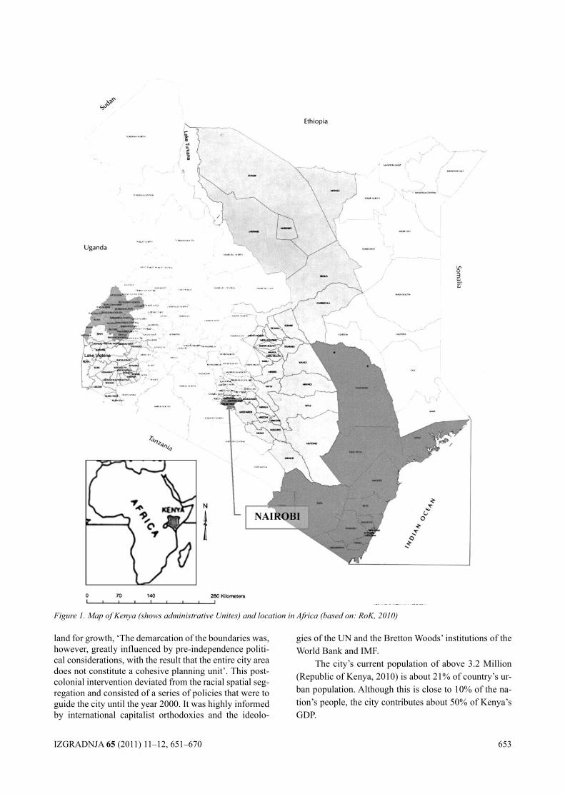
IZGRADNJA 65 (2011) 11–12, 651–670 653
land for growth, ‘The demarcation of the boundaries was, however, greatly influenced by pre-independence politi-cal considerations, with the result that the entire city area does not constitute a cohesive planning unit’. This post-colonial intervention deviated from the racial spatial seg-regation and consisted of a series of policies that were to guide the city until the year 2000. It was highly informed by international capitalist orthodoxies and the ideolo-
gies of the UN and the Bretton Woods’ institutions of the World Bank and IMF.
The city’s current population of above 3.2 Million (Republic of Kenya, 2010) is about 21% of country’s ur-ban population. Although this is close to 10% of the na-tion’s people, the city contributes about 50% of Kenya’s GDP.
Figure 1. Map of Kenya (shows administrative Unites) and location in Africa (based on: RoK, 2010)
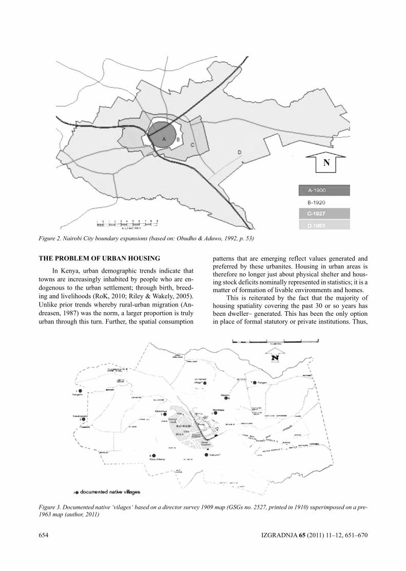
654 IZGRADNJA 65 (2011) 11–12, 651–670
ThE PROBlEM Of URBAN hOUSINg
In Kenya, urban demographic trends indicate that towns are increasingly inhabited by people who are en-dogenous to the urban settlement; through birth, breed-ing and livelihoods (RoK, 2010; Riley & Wakely, 2005). Unlike prior trends whereby rural-urban migration (An-dreasen, 1987) was the norm, a larger proportion is truly urban through this turn. Further, the spatial consumption
patterns that are emerging reflect values generated and preferred by these urbanites. Housing in urban areas is therefore no longer just about physical shelter and hous-ing stock deficits nominally represented in statistics; it is a matter of formation of livable environments and homes.
This is reiterated by the fact that the majority of housing spatiality covering the past 30 or so years has been dweller– generated. This has been the only option in place of formal statutory or private institutions. Thus,
Figure 2. Nairobi City boundary expansions (based on: Obudho & Aduwo, 1992, p. 53)
Figure 3. Documented native ‘vilages‘ based on a director survey 1909 map (GSGs no. 2527, printed in 1910) superimposed on a pre-1963 map (author, 2011)
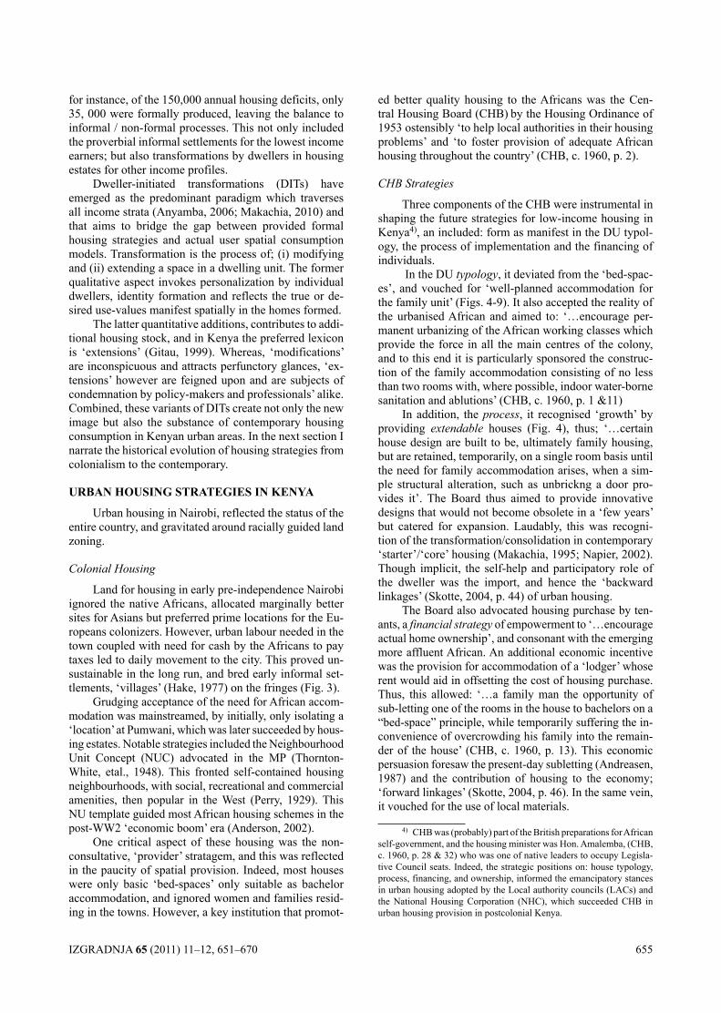
IZGRADNJA 65 (2011) 11–12, 651–670 655
for instance, of the 150,000 annual housing deficits, only 35, 000 were formally produced, leaving the balance to informal / non-formal processes. This not only included the proverbial informal settlements for the lowest income earners; but also transformations by dwellers in housing estates for other income profiles.
Dweller-initiated transformations (DITs) have emerged as the predominant paradigm which traverses all income strata (Anyamba, 2006; Makachia, 2010) and that aims to bridge the gap between provided formal housing strategies and actual user spatial consumption models. Transformation is the process of; (i) modifying and (ii) extending a space in a dwelling unit. The former qualitative aspect invokes personalization by individual dwellers, identity formation and reflects the true or de-sired use-values manifest spatially in the homes formed.
The latter quantitative additions, contributes to addi-tional housing stock, and in Kenya the preferred lexicon is ‘extensions’ (Gitau, 1999). Whereas, ‘modifications’ are inconspicuous and attracts perfunctory glances, ‘ex-tensions’ however are feigned upon and are subjects of condemnation by policy-makers and professionals’ alike. Combined, these variants of DITs create not only the new image but also the substance of contemporary housing consumption in Kenyan urban areas. In the next section I narrate the historical evolution of housing strategies from colonialism to the contemporary.
URBAN hOUSINg STRATEgIES IN KENyA
Urban housing in Nairobi, reflected the status of the entire country, and gravitated around racially guided land zoning.
Colonial Housing
Land for housing in early pre-independence Nairobi ignored the native Africans, allocated marginally better sites for Asians but preferred prime locations for the Eu-ropeans colonizers. However, urban labour needed in the town coupled with need for cash by the Africans to pay taxes led to daily movement to the city. This proved un-sustainable in the long run, and bred early informal set-tlements, ‘villages’ (Hake, 1977) on the fringes (Fig. 3).
Grudging acceptance of the need for African accom-modation was mainstreamed, by initially, only isolating a ‘location’ at Pumwani, which was later succeeded by hous-ing estates. Notable strategies included the Neighbourhood Unit Concept (NUC) advocated in the MP (Thornton-White, etal., 1948). This fronted self-contained housing neighbourhoods, with social, recreational and commercial amenities, then popular in the West (Perry, 1929). This NU template guided most African housing schemes in the post-WW2 ‘economic boom’ era (Anderson, 2002).
One critical aspect of these housing was the non-consultative, ‘provider’ stratagem, and this was reflected in the paucity of spatial provision. Indeed, most houses were only basic ‘bed-spaces’ only suitable as bachelor accommodation, and ignored women and families resid-ing in the towns. However, a key institution that promot-
ed better quality housing to the Africans was the Cen-tral Housing Board (CHB) by the Housing Ordinance of 1953 ostensibly ‘to help local authorities in their housing problems’ and ‘to foster provision of adequate African housing throughout the country’ (CHB, c. 1960, p. 2).
CHB Strategies
Three components of the CHB were instrumental in shaping the future strategies for low-income housing in Kenya4), an included: form as manifest in the DU typol-ogy, the process of implementation and the financing of individuals.
In the DU typology, it deviated from the ‘bed-spac-es’, and vouched for ‘well-planned accommodation for the family unit’ (Figs. 4-9). It also accepted the reality of the urbanised African and aimed to: ‘…encourage per-manent urbanizing of the African working classes which provide the force in all the main centres of the colony, and to this end it is particularly sponsored the construc-tion of the family accommodation consisting of no less than two rooms with, where possible, indoor water-borne sanitation and ablutions’ (CHB, c. 1960, p. 1 &11)
In addition, the process, it recognised ‘growth’ by providing extendable houses (Fig. 4), thus; ‘…certain house design are built to be, ultimately family housing, but are retained, temporarily, on a single room basis until the need for family accommodation arises, when a sim-ple structural alteration, such as unbrickng a door pro-vides it’. The Board thus aimed to provide innovative designs that would not become obsolete in a ‘few years’ but catered for expansion. Laudably, this was recogni-tion of the transformation/consolidation in contemporary ‘starter’/‘core’ housing (Makachia, 1995; Napier, 2002). Though implicit, the self-help and participatory role of the dweller was the import, and hence the ‘backward linkages’ (Skotte, 2004, p. 44) of urban housing.
The Board also advocated housing purchase by ten-ants, a financial strategy of empowerment to ‘…encourage actual home ownership’, and consonant with the emerging more affluent African. An additional economic incentive was the provision for accommodation of a ‘lodger’ whose rent would aid in offsetting the cost of housing purchase. Thus, this allowed: ‘…a family man the opportunity of sub-letting one of the rooms in the house to bachelors on a “bed-space” principle, while temporarily suffering the in-convenience of overcrowding his family into the remain-der of the house’ (CHB, c. 1960, p. 13). This economic persuasion foresaw the present-day subletting (Andreasen, 1987) and the contribution of housing to the economy; ‘forward linkages’ (Skotte, 2004, p. 46). In the same vein, it vouched for the use of local materials.
4) CHB was (probably) part of the British preparations for African self-government, and the housing minister was Hon. Amalemba, (CHB, c. 1960, p. 28 & 32) who was one of native leaders to occupy Legisla-tive Council seats. Indeed, the strategic positions on: house typology, process, financing, and ownership, informed the emancipatory stances in urban housing adopted by the Local authority councils (LACs) and the National Housing Corporation (NHC), which succeeded CHB in urban housing provision in postcolonial Kenya.
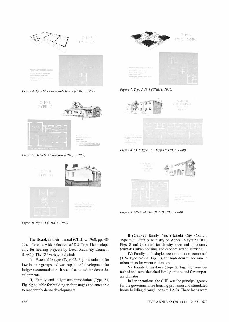
656 IZGRADNJA 65 (2011) 11–12, 651–670
The Board, in their manual (CHB, c. 1960, pp. 48-56), offered a wide selection of DU Type Plans adapt-able for housing projects by Local Authority Councils (LACs). The DU variety included:
I) Extendable type (Type 65, Fig. 4); suitable for low income groups and was capable of development for lodger accommodation. It was also suited for dense de-velopments.
II) Family and lodger accommodation (Type 53, Fig. 5); suitable for building in four stages and amenable to moderately dense developments.
III) 2-storey family flats (Nairobi City Council, Type “C” Ofafa & Ministry of Works “Mayfair Flats”, Figs. 8 and 9); suited for density town and up-country (climate) urban housing, and economised on services.
IV) Family and single accommodation combined (TPA Type 5-58-1, Fig. 7); for high density housing in urban areas for warmer climates
V) Family bungalows (Type 2, Fig. 5); were de-tached and semi-detached family units suited for temper-ate climates.
In her operations, the CHB was the principal agency for the government for housing provision and stimulated home-building through loans to LACs. These loans were
Figure 4. Type 65 - extendable house (CHB, c. 1960)
Figure 5. Detached bungalow (CHB, c. 1960)
Figure 6. Type 53 (CHB, c. 1960)
Figure 7. Type 5-58-1 (CHB, c. 1960)
Figure 8. CCN Type „C“ Ofafa (CHB, c. 1960)
Figure 9. MOW Mayfair flats (CHB, c. 1960)
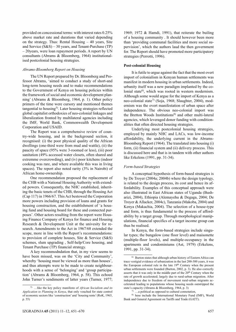
IZGRADNJA 65 (2011) 11–12, 651–670 657
provided on concessional terms: with interest rates 0.25% above market rate and durations that varied depending on the strategy. Thus: Rental Housing – 40 years, Site and Service (S&S) – 30 years, and Tenant-Purchase (TP) – 20years, were loan repayment periods. A report by UN consultants (Abrams & Bloomberg, 1964) institutional-ised postcolonial housing strategies.
Abrams-Bloomberg Report on Housing
The UN Report prepared by Dr. Bloomberg and Pro-fessor Abrams, ‘aimed to conduct a study of short-and long-term housing needs and to make recommendations to the Government of Kenya on housing policies within the framework of social and economic development plan-ning’ (Abrams & Bloomberg, 1964, p. 1). Other policy primers of the time were cursory and mentioned themes tangential to housing5). Later housing strategies reflected global capitalist orthodoxies of neo-colonial linkages and liberalization fronted by multilateral agencies including the IMF, World Bank, Commonwealth Development Corporation and USAID.
The Report was a comprehensive review of coun-try-wide housing, and in the background section, it recognised: (i) the poor physical quality of the African dwellings (one-third were from mud and wattle), (ii) the paucity of space (95% were 3-roomed or less), (iii) poor sanitation (49% accessed water closets, often shared and extremme overcrowding), and (iv) poor kitchens (indoor cooking was rare, and where available this was in living spaces). The report also noted rarity (3% in Nairobi) of African home-ownership.
One recommendation proposed the replacement of the CHB with a National Housing Authority with extend-ed powers. Consequently, the NHC established, inherit-ing the basic tenets of the CHB, through the Housing Act (Cap 117) in 1966/67. This Act bestowed the Corporation more powers including provision of loans and grants for housing construction, and the establishment of ‘a hous-ing fund and housing board for these and connected pur-poses’. Other actors resulting from the report were Hous-ing Finance Company of Kenya for finance and Housing Research & Development Unit at the univesity for re-search. Amendments to the Act in 1967/68 extended the scope, more in line with the Report’s recommendations: to provision of complete houses, Site & Service (S&S) schemes, slum upgrading , Self-help/Core housing, and Tenant Purchase (TP) financial strategy.
A key recommodndation that, in my view seems to have been missed, was on the ‘City and Community’, whereby ‘housing must be viewed as more than houses’, and thus attempts were to be made to create neighbour-hoods with a sense of ‘belonging’ and ‘group participa-tion’ (Abrams & Bloomberg, 1964, p. 58). This echoed John Turner’s sendiments of latter years (Turner, 1977;
5) …like the key policy manifesto of African Socialism and its Application to Planning in Kenya, that only vouched for state control of economic sectors like ‘construction’ and ‘housing rents’ (RoK, 1965, p. 55)
1969; 1972 & Hamdi, 1991), that reiterate the builing of a housing community . It should however been more than ‘providing communal facilities and more social su-pervision’, which the authors laud the then government for. The Report should have promoted more participatory strategies (Perrotti, 1996).
Post-colonial housing
It is futile to argue against the fact that the most overt import of colonialism in Kenyan human settlements was manifest in modern housing in urban settlements. Indeed, urbanity itself was a new paradigm implanted by the co-lonial state6), which was rooted in western modernism. Although some would argue for the import of Kenya as a neo-colonial state7) (Soja, 1968; Slaughter, 2004), mod-ernism was the overt manifestation of urban space after independence. The obvious neo-colonial import was the Bretton Woods Institutions8) and other multi-lateral agencies, which leveraged donor funding with condition-alities that often directed housing strategies.
Underlying most postcolonial housing strategies, employed by mainly NHC and LACs, was low-income affordability, the underlying current in the Abrams-Bloomberg Report (1964). The translated into housing (i) form, (ii) financial system and (ii) delivery process. This is discussed here and that is in tandem with other authors like Erkelens (1991, pp. 31-34).
Form-based Strategies
A conceptual hypothesis of form-based strategies is by De Troyer (2004a; 2004b) where the design typology, is related to the design process, its cost and hence its af-fordability. Examples of this conceptual approach were also illustrated in East African states of Uganda (Bush-arizi, 2004), Ethiopia (Alemayehu & Degaga, 2004; De Troyer & Allacker, 2004c), Tanzania (Makoba, 2004) and Kenya (Makachia, 2004). The selection of a house-type and form, is thus fundamental to the process of afford-ability by a target group. Through morphological manip-ulations, financial specifics of a target income group can thus be realised.
In Kenya, the form-based strategies include singu-lar types; the bungalow (one floor level) and maisonette (multiple-floor levels), and multiple-occupancy in the apartments and condominiums (Ast, 1979) (Erkelens, 1991, pp. 31-34).
6) Burton states that although urban history of Eastern Africa can trace vestigial evidence of urbanization in the last 200-300 years, it was the European colonial rule in the late 19th Century when the present urban settlements were founded (Burton, 2002, p. 3). He also correctly asserts that it was only in the middle part of the 20th Century when the rate of growth accelerated; largely due to rural-urban migration. After independence due to freedom of movement rural-urban migrants ac-celerated leading to populations whose housing needs outstripped the state’s capacity (Abrams & Bloomberg, 1964, p. 3)
7) …a political as opposed to cultural connotation,8) hese include the International Monetary Fund (IMF), World
Bank and General Agreement on Tariffs and Trade (GATT).
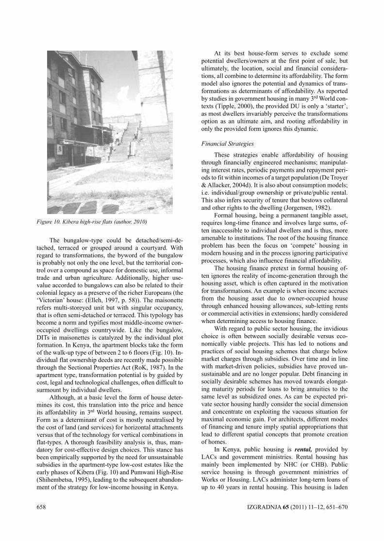
658 IZGRADNJA 65 (2011) 11–12, 651–670
The bungalow-type could be detached/semi-de-tached, terraced or grouped around a courtyard. With regard to transformations, the byword of the bungalow is probably not only the one level, but the territorial con-trol over a compound as space for domestic use, informal trade and urban agriculture. Additionally, higher use-value accorded to bungalows can also be related to their colonial legacy as a preserve of the richer Europeans (the ‘Victorian’ house: (Elleh, 1997, p. 58)). The maisonette refers multi-storeyed unit but with singular occupancy, that is often semi-detached or terraced. This typology has become a norm and typifies most middle-income owner-occupied dwellings countrywide. Like the bungalow, DITs in maisonettes is catalyzed by the individual plot formation. In Kenya, the apartment blocks take the form of the walk-up type of between 2 to 6 floors (Fig. 10). In-dividual flat ownership deeds are recently made possible through the Sectional Properties Act (RoK, 1987). In the apartment type, transformation potential is by guided by cost, legal and technological challenges, often difficult to surmount by individual dwellers.
Although, at a basic level the form of house deter-mines its cost, this translation into the price and hence its affordability in 3rd World housing, remains suspect. Form as a determinant of cost is mostly neutralised by the cost of land (and services) for horizontal attachments versus that of the technology for vertical combinations in flat-types. A thorough feasibility analysis is, thus, man-datory for cost-effective design choices. This stance has been empirically supported by the need for unsustainable subsidies in the apartment-type low-cost estates like the early phases of Kibera (Fig. 10) and Pumwani High-Rise (Shihembetsa, 1995), leading to the subsequent abandon-ment of the strategy for low-income housing in Kenya.
At its best house-form serves to exclude some potential dwellers/owners at the first point of sale, but ultimately, the location, social and financial considera-tions, all combine to determine its affordability. The form model also ignores the potential and dynamics of trans-formations as determinants of affordability. As reported by studies in government housing in many 3rd World con-texts (Tipple, 2000), the provided DU is only a ‘starter’, as most dwellers invariably perceive the transformations option as an ultimate aim, and rooting affordability in only the provided form ignores this dynamic.
Financial Strategies
These strategies enable affordability of housing through financially engineered mechanisms; manipulat-ing interest rates, periodic payments and repayment peri-ods to fit within incomes of a target population (De Troyer & Allacker, 2004d). It is also about consumption models; i.e. individual/group ownership or private/public rental. This also infers security of tenure that bestows collateral and other rights to the dwelling (Jorgensen, 1982).
Formal housing, being a permanent tangible asset, requires long-time finance and involves large sums, of-ten inaccessible to individual dwellers and is thus, more amenable to institutions. The root of the housing finance problem has been the focus on ‘compete’ housing in modern housing and in the process ignoring participative processes, which also influence financial affordability.
The housing finance pretext in formal housing of-ten ignores the reality of income-generation through the housing asset, which is often captured in the motivation for transformations. An example is when income accrues from the housing asset due to owner-occupied house through enhanced housing allowances, sub-letting rents or commercial activities in extensions; hardly considered when determining access to housing finance.
With regard to public sector housing, the invidious choice is often between socially desirable versus eco-nomically viable projects. This has led to notions and practices of social housing schemes that charge below market charges through subsidies. Over time and in line with market-driven policies, subsidies have proved un-sustainable and are no longer popular. Debt financing in socially desirable schemes has moved towards elongat-ing maturity periods for loans to bring annuities to the same level as subsidized ones. As can be expected pri-vate sector housing hardly consider the social dimension and concentrate on exploiting the vacuous situation for maximal economic gain. For architects, different modes of financing and tenure imply spatial appropriations that lead to different spatial concepts that promote creation of homes.
In Kenya, public housing is rental, provided by LACs and government ministries. Rental housing has mainly been implemented by NHC (or CHB). Public service housing is through government ministries of Works or Housing. LACs administer long-term loans of up to 40 years in rental housing. This housing is laden
Figure 10. Kibera high-rise flats (author, 2010)
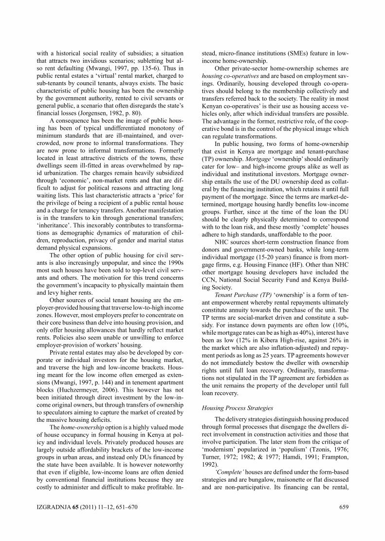
IZGRADNJA 65 (2011) 11–12, 651–670 659
with a historical social reality of subsidies; a situation that attracts two invidious scenarios; subletting but al-so rent defaulting (Mwangi, 1997, pp. 135-6). Thus in public rental estates a ‘virtual’ rental market, charged to sub-tenants by council tenants, always exists. The basic characteristic of public housing has been the ownership by the government authority, rented to civil servants or general public, a scenario that often disregards the state’s financial losses (Jorgensen, 1982, p. 80).
A consequence has been the image of public hous-ing has been of typical undifferentiated monotony of minimum standards that are ill-maintained, and over-crowded, now prone to informal transformations. They are now prone to informal transformations. Formerly located in least attractive districts of the towns, these dwellings seem ill-fitted in areas overwhelmed by rap-id urbanization. The charges remain heavily subsidized through ‘economic’, non-market rents and that are dif-ficult to adjust for political reasons and attracting long waiting lists. This last characteristic attracts a ‘price’ for the privilege of being a recipient of a public rental house and a charge for tenancy transfers. Another manifestation is in the transfers to kin through generational transfers; ‘inheritance’. This inexorably contributes to transforma-tions as demographic dynamics of maturation of chil-dren, reproduction, privacy of gender and marital status demand physical expansions.
The other option of public housing for civil serv-ants is also increasingly unpopular, and since the 1990s most such houses have been sold to top-level civil serv-ants and others. The motivation for this trend concerns the government’s incapacity to physically maintain them and levy higher rents.
Other sources of social tenant housing are the em-ployer-provided housing that traverse low-to-high income zones. However, most employers prefer to concentrate on their core business than delve into housing provision, and only offer housing allowances that hardly reflect market rents. Policies also seem unable or unwilling to enforce employer-provision of workers’ housing.
Private rental estates may also be developed by cor-porate or individual investors for the housing market, and traverse the high and low-income brackets. Hous-ing meant for the low income often emerged as exten-sions (Mwangi, 1997, p. 144) and in tenement apartment blocks (Huchzermeyer, 2006). This however has not been initiated through direct investment by the low-in-come original owners, but through transfers of ownership to speculators aiming to capture the market of created by the massive housing deficits.
The home-ownership option is a highly valued mode of house occupancy in formal housing in Kenya at pol-icy and individual levels. Privately produced houses are largely outside affordability brackets of the low-income groups in urban areas, and instead only DUs financed by the state have been available. It is however noteworthy that even if eligible, low-income loans are often denied by conventional financial institutions because they are costly to administer and difficult to make profitable. In-
stead, micro-finance institutions (SMEs) feature in low-income home-ownership.
Other private-sector home-ownership schemes are housing co-operatives and are based on employment sav-ings. Ordinarily, housing developed through co-opera-tives should belong to the membership collectively and transfers referred back to the society. The reality in most Kenyan co-operatives’ is their use as housing access ve-hicles only, after which individual transfers are possible. The advantage in the former, restrictive role, of the coop-erative bond is in the control of the physical image which can regulate transformations.
In public housing, two forms of home-ownership that exist in Kenya are mortgage and tenant-purchase (TP) ownership. Mortgage ‘ownership’ should ordinarily cater for low– and high-income groups alike as well as individual and institutional investors. Mortgage owner-ship entails the use of the DU ownership deed as collat-eral by the financing institution, which retains it until full payment of the mortgage. Since the terms are market-de-termined, mortgage housing hardly benefits low-income groups. Further, since at the time of the loan the DU should be clearly physically determined to correspond with to the loan risk, and these mostly ‘complete’ houses adhere to high standards, unaffordable to the poor.
NHC sources short-term construction finance from donors and government-owned banks, while long-term individual mortgage (15-20 years) finance is from mort-gage firms, e.g. Housing Finance (HF). Other than NHC other mortgage housing developers have included the CCN, National Social Security Fund and Kenya Build-ing Society.
Tenant Purchase (TP) ‘ownership’ is a form of ten-ant empowerment whereby rental repayments ultimately constitute annuity towards the purchase of the unit. The TP terms are social-market driven and constitute a sub-sidy. For instance down payments are often low (10%, while mortgage rates can be as high as 40%), interest have been as low (12% in Kibera High-rise, against 26% in the market which are also inflation-adjusted) and repay-ment periods as long as 25 years. TP agreements however do not immediately bestow the dweller with ownership rights until full loan recovery. Ordinarily, transforma-tions not stipulated in the TP agreement are forbidden as the unit remains the property of the developer until full loan recovery.
Housing Process Strategies
The delivery strategies distinguish housing produced through formal processes that disengage the dwellers di-rect involvement in construction activities and those that involve participation. The later stem from the critique of ‘modernism’ popularized in ‘populism’ (Tzonis, 1976; Turner, 1972; 1982; & 1977; Hamdi, 1991; Frampton, 1992).
‘Complete’ houses are defined under the form-based strategies and are bungalow, maisonette or flat discussed and are non-participative. Its financing can be rental,
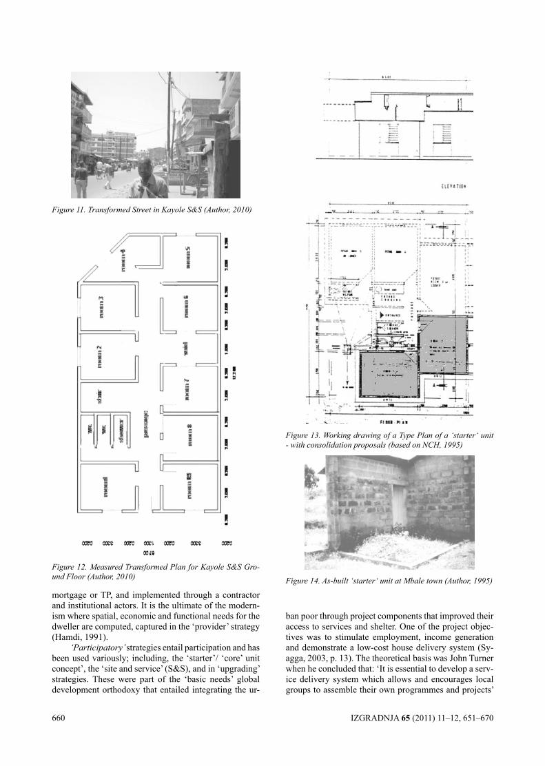
660 IZGRADNJA 65 (2011) 11–12, 651–670
mortgage or TP, and implemented through a contractor and institutional actors. It is the ultimate of the modern-ism where spatial, economic and functional needs for the dweller are computed, captured in the ‘provider’ strategy (Hamdi, 1991).
‘Participatory’ strategies entail participation and has been used variously; including, the ‘starter’/ ‘core’ unit concept’, the ‘site and service’ (S&S), and in ‘upgrading’ strategies. These were part of the ‘basic needs’ global development orthodoxy that entailed integrating the ur-
ban poor through project components that improved their access to services and shelter. One of the project objec-tives was to stimulate employment, income generation and demonstrate a low-cost house delivery system (Sy-agga, 2003, p. 13). The theoretical basis was John Turner when he concluded that: ‘It is essential to develop a serv-ice delivery system which allows and encourages local groups to assemble their own programmes and projects’
Figure 11. Transformed Street in Kayole S&S (Author, 2010)
Figure 12. Measured Transformed Plan for Kayole S&S Gro-und Floor (Author, 2010)
Figure 13. Working drawing of a Type Plan of a ‘starter‘ unit - with consolidation proposals (based on NCH, 1995)
Figure 14. As-built ‘starter‘ unit at Mbale town (Author, 1995)
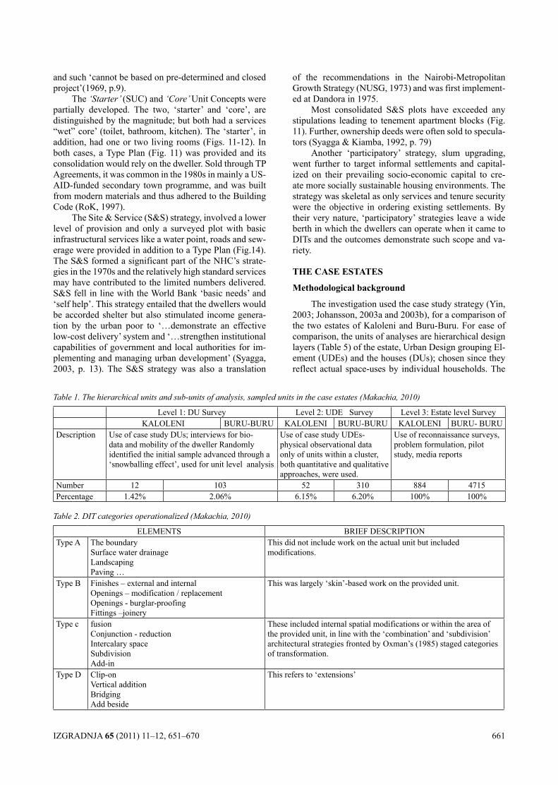
IZGRADNJA 65 (2011) 11–12, 651–670 661
and such ‘cannot be based on pre-determined and closed project’(1969, p.9).
The ‘Starter’ (SUC) and ‘Core’ Unit Concepts were partially developed. The two, ‘starter’ and ‘core’, are distinguished by the magnitude; but both had a services “wet” core’ (toilet, bathroom, kitchen). The ‘starter’, in addition, had one or two living rooms (Figs. 11-12). In both cases, a Type Plan (Fig. 11) was provided and its consolidation would rely on the dweller. Sold through TP Agreements, it was common in the 1980s in mainly a US-AID-funded secondary town programme, and was built from modern materials and thus adhered to the Building Code (RoK, 1997).
The Site & Service (S&S) strategy, involved a lower level of provision and only a surveyed plot with basic infrastructural services like a water point, roads and sew-erage were provided in addition to a Type Plan (Fig.14). The S&S formed a significant part of the NHC’s strate-gies in the 1970s and the relatively high standard services may have contributed to the limited numbers delivered. S&S fell in line with the World Bank ‘basic needs’ and ‘self help’. This strategy entailed that the dwellers would be accorded shelter but also stimulated income genera-tion by the urban poor to ‘…demonstrate an effective low-cost delivery’ system and ‘…strengthen institutional capabilities of government and local authorities for im-plementing and managing urban development’ (Syagga, 2003, p. 13). The S&S strategy was also a translation
of the recommendations in the Nairobi-Metropolitan Growth Strategy (NUSG, 1973) and was first implement-ed at Dandora in 1975.
Most consolidated S&S plots have exceeded any stipulations leading to tenement apartment blocks (Fig. 11). Further, ownership deeds were often sold to specula-tors (Syagga & Kiamba, 1992, p. 79)
Another ‘participatory’ strategy, slum upgrading, went further to target informal settlements and capital-ized on their prevailing socio-economic capital to cre-ate more socially sustainable housing environments. The strategy was skeletal as only services and tenure security were the objective in ordering existing settlements. By their very nature, ‘participatory’ strategies leave a wide berth in which the dwellers can operate when it came to DITs and the outcomes demonstrate such scope and va-riety.
ThE cASE ESTATES
Methodological background
The investigation used the case study strategy (Yin, 2003; Johansson, 2003a and 2003b), for a comparison of the two estates of Kaloleni and Buru-Buru. For ease of comparison, the units of analyses are hierarchical design layers (Table 5) of the estate, Urban Design grouping El-ement (UDEs) and the houses (DUs); chosen since they reflect actual space-uses by individual households. The
Table 1. The hierarchical units and sub-units of analysis, sampled units in the case estates (Makachia, 2010)
Level 1: DU Survey Level 2: UDE Survey Level 3: Estate level Survey KALOLENI BURU-BURU KALOLENI BURU-BURU KALOLENI BURU- BURUDescription Use of case study DUs; interviews for bio-
data and mobility of the dweller Randomly identified the initial sample advanced through a ‘snowballing effect’, used for unit level analysis
Use of case study UDEs- physical observational data only of units within a cluster, both quantitative and qualitative approaches, were used.
Use of reconnaissance surveys, problem formulation, pilot study, media reports
Number 12 103 52 310 884 4715Percentage 1.42% 2.06% 6.15% 6.20% 100% 100%
Table 2. DIT categories operationalized (Makachia, 2010)
ELEMENTS BRIEF DESCRIPTIONType A The boundary
Surface water drainageLandscapingPaving …
This did not include work on the actual unit but included modifications.
Type B Finishes – external and internalOpenings – modification / replacement Openings - burglar-proofingFittings –joinery
This was largely ‘skin’-based work on the provided unit.
Type c fusionConjunction - reductionIntercalary space Subdivision Add-in
These included internal spatial modifications or within the area of the provided unit, in line with the ‘combination’ and ‘subdivision’ architectural strategies fronted by Oxman’s (1985) staged categories of transformation.
Type D Clip-on Vertical addition Bridging Add beside
This refers to ‘extensions’
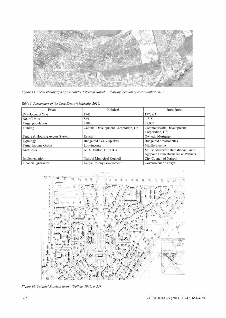
662 IZGRADNJA 65 (2011) 11–12, 651–670
Figure 15. Aerial photograph of Eastland‘s district of Nairobi - showing location of cases (author 2010)
Figure 16. Original Kaloleni layout (Ogilvic, 1946, p. 25)
Table 3. Parameters of the Case Estate (Makachia, 2010)
Estate Kaloleni Buru-Buru Development Year 1945 1973-83No. of Units 884 4,715Target population 3,000 35,000Funding Colonial Development Corporation, UK Commonwealth Development
Corporation, UKTenure & Housing Access System Rental Owned / Mortgage Typology Bungaloid / walk-up flats Bungaloid / maisonettes Target Income Group Low-income Middle-incomeArchitects A.J.S. Hutton, F.R.I.B.A. Mutiso Menezes International, Paviz
Agepour, Colin Buchanan & Partners.Implementation Nairobi Municipal Council City Council of NairobiFinancial guarantor Kenya Colony Government Government of Kenya
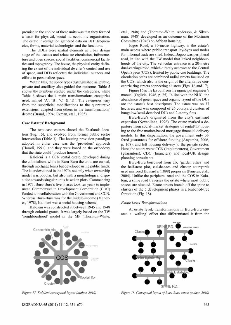
IZGRADNJA 65 (2011) 11–12, 651–670 663
premise in the choice of these units was that they formed a basis for physical, social nd economic organisation. The estate investigation gathered data on DIT: frequen-cies, forms, material technologies and the functions.
The UDEs were spatial elements at urban design stage of the estates and relate to: circulation, infrastruc-ture and open spaces, social facilities, commercial facili-ties and topography. The house, the physical entity defin-ing the extent of the individual dweller’s control and use of space, and DITs reflected the individual nuances and efforts to personalize space.
Within this, the space types distinguished as: public, private and ancillary also guided the outcome. Table 5 shows the numbers studied under the categories, while Table 6 shows the 4 main transformations categories used, named ‘A’, ‘B’, ‘C’ & ‘D’. The categories vary from the superficial modifications to the quantitative extensions, adapted from others in the transformations’ debate (Brand, 1994; Oxman, etal., 1985).
case Estates’ Background
The two case estates shared the Eastlands loca-tion (Fig. 15), and evolved from formal public sector intervention (Table 3). The housing provision paradigm adopted in either case was the ‘providers’ approach (Hamdi, 1991), and they were based on the orthodoxy that the state could ‘produce houses’.
Kaloleni is a CCN rental estate, developed during the colonialism, while in Buru-Buru the units are owned, through mortgage loans but developed using public funds. The later developed in the 1970s not only when ownership model was popular, but also with a morphological dispo-sition towards singular units based on plots. Commencing in 1973, Buru-Buru’s five phases took ten years to imple-ment. Commonwealth Development Corporation (CDC) funded it in collaboration with the Government and CCN. Whereas Buru-Buru was for the middle-income (Menez-es, 1978), Kaloleni was a social housing scheme.
Kaloleni was constructed at between 1945 and 1948 through colonial grants. It was largely based on the TW ‘neighbourhood’ model in the MP (Thornton-White,
etal., 1948) and (Thornton-White, Anderson, & Silver-man, 1948) developed as an outcome of the Mortimer Committee (1946) on African housing.
Jogoo Road, a 30-metre highway, is the estate’s main access where public transport lay-byes and nodes for informal trade are sited. Indeed, Jogoo was peripheral road, in line with the TW model that linked neighbour-hoods of the city. The vehicular entrance is a 20-metre dual-carriage road, which directly accesses to the Central Open Space (COS), fronted by public-use buildings. The circulation paths are combined radial streets focussed on the COS, which also is the origin of the alternative con-centric ring streets connecting clusters (Figs. 16 and 17).
Figure 16 is the layout from the municipal engineer’s manual (Ogilvie, 1946, p. 25). In line with the NUC, the abundance of green space and organic layout of the DUs are the estate’s best descriptors. The estate was on 37 hectares, and was composed of 26 courtyard clusters of bungalow/semi-detached DUs and 2-storey flats.
Buru-Buru’s originated from the city’s eastward expansion (Nevanlinna, 1996). The estate marked a de-parture from social-market strategies of rental/TP hous-ing to the free market-based mortgage financial delivery models. In this dispensation, the government only of-fered guarantees for offshore funding (Anyamba, 2006, p. 168), and left housing delivery to the private sector. Here, the actors were: CCN (implementers), Government (guarantors), CDC (financiers) and local/UK design/planning consultants.
Buru-Buru borrowed from UK ‘garden cities’ and the half-acre plot, cul-de-sacs and cluster courtyards used mirrored Howard’s (1898) proposals (Panerai, etal., 2004). Unlike the peripheral road and the COS in Kalo-leni, a spine road traverses the estate where most public spaces are situated. Estate streets branch off the spine to clusters of the 5 development phases in a brabched-tree formation (Fig. 18).
Estate Level Transformations
At estate level, transformations in Buru-Buru cre-ated a ‘walling’ effect that differentiated it from the
Figure 17. Kaloleni conceptual layout (author, 2010) Figure 18. Conceptual layout of Buru-Buru estate (author, 2010)
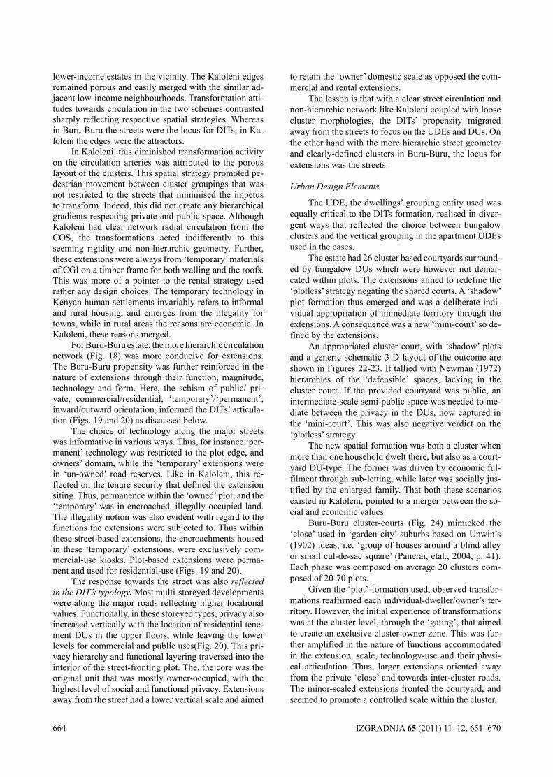
664 IZGRADNJA 65 (2011) 11–12, 651–670
lower-income estates in the vicinity. The Kaloleni edges remained porous and easily merged with the similar ad-jacent low-income neighbourhoods. Transformation atti-tudes towards circulation in the two schemes contrasted sharply reflecting respective spatial strategies. Whereas in Buru-Buru the streets were the locus for DITs, in Ka-loleni the edges were the attractors.
In Kaloleni, this diminished transformation activity on the circulation arteries was attributed to the porous layout of the clusters. This spatial strategy promoted pe-destrian movement between cluster groupings that was not restricted to the streets that minimised the impetus to transform. Indeed, this did not create any hierarchical gradients respecting private and public space. Although Kaloleni had clear network radial circulation from the COS, the transformations acted indifferently to this seeming rigidity and non-hierarchic geometry. Further, these extensions were always from ‘temporary’ materials of CGI on a timber frame for both walling and the roofs. This was more of a pointer to the rental strategy used rather any design choices. The temporary technology in Kenyan human settlements invariably refers to informal and rural housing, and emerges from the illegality for towns, while in rural areas the reasons are economic. In Kaloleni, these reasons merged.
For Buru-Buru estate, the more hierarchic circulation network (Fig. 18) was more conducive for extensions. The Buru-Buru propensity was further reinforced in the nature of extensions through their function, magnitude, technology and form. Here, the schism of public/ pri-vate, commercial/residential, ‘temporary’/‘permanent’, inward/outward orientation, informed the DITs’ articula-tion (Figs. 19 and 20) as discussed below.
The choice of technology along the major streets was informative in various ways. Thus, for instance ‘per-manent’ technology was restricted to the plot edge, and owners’ domain, while the ‘temporary’ extensions were in ‘un-owned’ road reserves. Like in Kaloleni, this re-flected on the tenure security that defined the extension siting. Thus, permanence within the ‘owned’ plot, and the ‘temporary’ was in encroached, illegally occupied land. The illegality notion was also evident with regard to the functions the extensions were subjected to. Thus within these street-based extensions, the encroachments housed in these ‘temporary’ extensions, were exclusively com-mercial-use kiosks. Plot-based extensions were perma-nent and used for residential-use (Figs. 19 and 20).
The response towards the street was also reflected in the DIT’s typology. Most multi-storeyed developments were along the major roads reflecting higher locational values. Functionally, in these storeyed types, privacy also increased vertically with the location of residential tene-ment DUs in the upper floors, while leaving the lower levels for commercial and public uses(Fig. 20). This pri-vacy hierarchy and functional layering traversed into the interior of the street-fronting plot. The, the core was the original unit that was mostly owner-occupied, with the highest level of social and functional privacy. Extensions away from the street had a lower vertical scale and aimed
to retain the ‘owner’ domestic scale as opposed the com-mercial and rental extensions.
The lesson is that with a clear street circulation and non-hierarchic network like Kaloleni coupled with loose cluster morphologies, the DITs’ propensity migrated away from the streets to focus on the UDEs and DUs. On the other hand with the more hierarchic street geometry and clearly-defined clusters in Buru-Buru, the locus for extensions was the streets.
Urban Design Elements
The UDE, the dwellings’ grouping entity used was equally critical to the DITs formation, realised in diver-gent ways that reflected the choice between bungalow clusters and the vertical grouping in the apartment UDEs used in the cases.
The estate had 26 cluster based courtyards surround-ed by bungalow DUs which were however not demar-cated within plots. The extensions aimed to redefine the ‘plotless’ strategy negating the shared courts. A ‘shadow’ plot formation thus emerged and was a deliberate indi-vidual appropriation of immediate territory through the extensions. A consequence was a new ‘mini-court’ so de-fined by the extensions.
An appropriated cluster court, with ‘shadow’ plots and a generic schematic 3-D layout of the outcome are shown in Figures 22-23. It tallied with Newman (1972) hierarchies of the ‘defensible’ spaces, lacking in the cluster court. If the provided courtyard was public, an intermediate-scale semi-public space was needed to me-diate between the privacy in the DUs, now captured in the ‘mini-court’. This was also negative verdict on the ‘plotless’ strategy.
The new spatial formation was both a cluster when more than one household dwelt there, but also as a court-yard DU-type. The former was driven by economic ful-filment through sub-letting, while later was socially jus-tified by the enlarged family. That both these scenarios existed in Kaloleni, pointed to a merger between the so-cial and economic values.
Buru-Buru cluster-courts (Fig. 24) mimicked the ‘close’ used in ‘garden city’ suburbs based on Unwin’s (1902) ideas; i.e. ‘group of houses around a blind alley or small cul-de-sac square’ (Panerai, etal., 2004, p. 41). Each phase was composed on average 20 clusters com-posed of 20-70 plots.
Given the ‘plot’-formation used, observed transfor-mations reaffirmed each individual-dweller/owner’s ter-ritory. However, the initial experience of transformations was at the cluster level, through the ‘gating’, that aimed to create an exclusive cluster-owner zone. This was fur-ther amplified in the nature of functions accommodated in the extension, scale, technology-use and their physi-cal articulation. Thus, larger extensions oriented away from the private ‘close’ and towards inter-cluster roads. The minor-scaled extensions fronted the courtyard, and seemed to promote a controlled scale within the cluster.
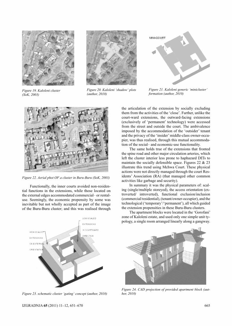
IZGRADNJA 65 (2011) 11–12, 651–670 665
Figure 19. Kaloleni cluster (SoK, 2003)
Figure 20. Kaloleni ‘shadow‘ plots (author, 2010)
Figure 21. Kaloleni generic ‘minicluster‘ formation (author, 2010)
Figure 22. Aerial phot OF a cluster in Buru-Buru (SoK, 2003)
the articulation of the extension by socially excluding them from the activities of the ‘close’. Further, unlike the court-ward extensions, the outward-facing extensions (exclusively of ‘permanent’ technology) were accessed from the street and outside the court. The ambivalence imposed by the accommodation of the ‘outsider’ tenant and the privacy of the ‘insider’ middle-class owner-occu-pier, was thus realised, through this mutual accommoda-tion of the social– and economic-use functionality.
The same holds true of the extensions that fronted the spine road and other major circulation arteries, which left the cluster interior less prone to haphazard DITs to maintain the socially defensible space. Figures 22 & 23 illustrate this trend using Mchwa Court. These physical actions were not directly managed through the court Res-idents’ Association (RA) (that managed other common activities like garbage and security).
In summary it was the physical parameters of: scal-ing (single/multiple storeyed), the access orientation (ex-troverted/ introverted), functional exclusion/inclusion (commercial/residential), (tenant/owner-occupier), and the technological (‘temporary’/‘permanent’), all which guided the extension propensities in these Buru-Buru clusters.
The apartment blocks were located in the ‘Gorofani’ zone of Kaloleni estate, and used only one simple unit ty-pology, a single room arranged linearly along a gangway.
Figure 23. schematic cluster ‘gating‘ concept (author, 2010)Figure 24. CAD projection of provided apartment block (aut-hor, 2010)
Functionally, the inner courts avoided non-residen-tial functions in the extensions, while those located on the external edges accommodated commercial– or rental-use. Seemingly, the economic propensity by some was inevitable but not wholly accepted as part of the image of the Buru-Buru cluster; and this was realised through
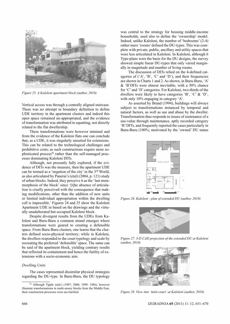
666 IZGRADNJA 65 (2011) 11–12, 651–670
Figure 25. A Kaloleni apartment block (author, 2010)
Figure 26. Kaloleni - plan of extended DU (author, 2010)
Figure 27. 3-D CAD projection of the extended DU at Kaloleni (author, 2010)
Figure 28. View into ‘mini-court‘ at Kaloleni (author, 2010)
Vertical access was through a centrally aligned staircase. There was no attempt in boundary definition to define UDE territory in the apartment clusters and indeed this open space remained un-appropriated, and the evidence of transformation was attributed to squatting, not directly related to the flat dwellership.
These transformations were however minimal and from the evidence of the Kaloleni flats one can conclude that, as a UDE, it was singularly unsuited for extensions. This can be related to the technological challenges and prohibitive costs; as such constructions require more so-phisticated process9) rather than the self-managed proc-esses dominating Kaloleni DITs.
Although, not presently fully explored, if the evi-dence of DITs was the measure, then the apartment UDE can be termed as a ‘negation of the city’ in the 3rd World, as also articulated by Panerai’s (etal) (2004, p. 121) study of urban blocks. Indeed, they perceive it as the ‘last meta-morphosis of the block’ since ‘[t]he absence of articula-tion is cruelly perceived with the consequence that mak-ing modifications, other than the addition of new units or limited individual appropriation within the dwelling cell is impossible.’ Figures 24 and 25 show the Kaloleni Apartment UDE in based on the drawings and the virtu-ally unadulterated but occupied Kaloleni block.
Despite divergent results from the UDEs from Ka-loleni and Buru-Buru a common strand emerges where transformations were geared to creating a defensible space. From Buru-Buru clusters, one learns that the clus-ters defined socio-physical territory; while in Kaloleni, the dwellers responded to the court typology and scale by recreating the preferred ‘defensible’ space. The same can be said of the apartment block, yielding contrary results that reflected its containment and hence the futility of ex-tensions with a socio-economic aim.
Dwelling Units
The cases represented dissimilar physical strategies regarding the DU-type. In Buru-Buru, the DU typology
9) Although Tipple (etal.) (1987; 2000; 1999; 1986), however illustrate transformations in multi-storey blocks from the Middle East, their construction processes were un-clarified.
was central to the strategy for housing middle-income households, used also to define the ‘ownership’ model. Indeed, unlike Kaloleni, the number of ‘bedrooms’ (2-4) rather mere ‘rooms’ defined the DU-types. This was com-plete with private, public, ancillary and utility spaces that were less articulated in Kaloleni. In Kaloleni, although 6 Type-plans were the basis for the DU designs, the survey showed simple linear DU-types that only varied margin-ally in magnitude and number of living rooms.
The discussion of DITs relied on the 4-defined cat-egories of (‘A’, ‘B’, ‘C’ and ‘D’), and their frequencies are shown in Charts 1 and 2. As shown, in Buru-Buru, ‘A’ & ‘B’DITs were almost inevitable, with a 50% chance for ‘C’ and ‘D’ categories. For Kaloleni, two-thirds of the dwellers were likely to have categories ‘B’, ‘C’ & ‘D’, with only 10% engaging in category ‘A’.
As asserted by Brand (1994), buildings will always subject to transformations instanced by temporal and natural factors, as well as use and abuse by the dweller. Transformation thus responds to issues of sustenance of a use-value through maintenance, aptly recorded category ‘B’ DITs, and frequently reported the cases particularly in Buru-Buru (100%; motivated by the ‘owned’ DU status
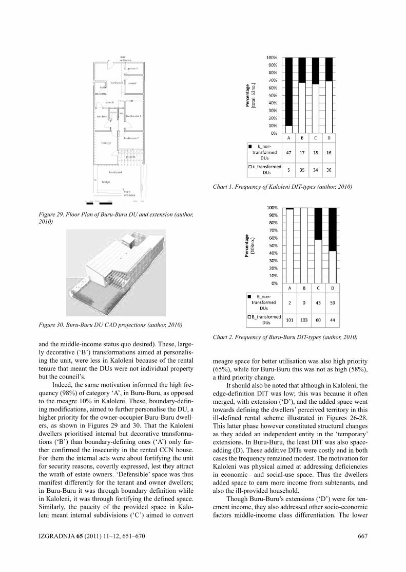
IZGRADNJA 65 (2011) 11–12, 651–670 667
Chart 1. Frequency of Kaloleni DIT-types (author, 2010)
Chart 2. Frequency of Buru-Buru DIT-types (author, 2010)
Figure 29. Floor Plan of Buru-Buru DU and extension (author, 2010)
Figure 30. Buru-Buru DU CAD projections (author, 2010)
and the middle-income status quo desired). These, large-ly decorative (‘B’) transformations aimed at personalis-ing the unit, were less in Kaloleni because of the rental tenure that meant the DUs were not individual property but the council’s.
Indeed, the same motivation informed the high fre-quency (98%) of category ‘A’, in Buru-Buru, as opposed to the meagre 10% in Kaloleni. These, boundary-defin-ing modifications, aimed to further personalise the DU, a higher priority for the owner-occupier Buru-Buru dwell-ers, as shown in Figures 29 and 30. That the Kaloleni dwellers prioritised internal but decorative transforma-tions (‘B’) than boundary-defining ones (‘A’) only fur-ther confirmed the insecurity in the rented CCN house. For them the internal acts were about fortifying the unit for security reasons, covertly expressed, lest they attract the wrath of estate owners. ‘Defensible’ space was thus manifest differently for the tenant and owner dwellers; in Buru-Buru it was through boundary definition while in Kaloleni, it was through fortifying the defined space. Similarly, the paucity of the provided space in Kalo-leni meant internal subdivisions (‘C’) aimed to convert
meagre space for better utilisation was also high priority (65%), while for Buru-Buru this was not as high (58%), a third priority change.
It should also be noted that although in Kaloleni, the edge-definition DIT was low; this was because it often merged, with extension (‘D’), and the added space went towards defining the dwellers’ perceived territory in this ill-defined rental scheme illustrated in Figures 26-28. This latter phase however constituted structural changes as they added an independent entity in the ‘temporary’ extensions. In Buru-Buru, the least DIT was also space-adding (D). These additive DITs were costly and in both cases the frequency remained modest. The motivation for Kaloleni was physical aimed at addressing deficiencies in economic– and social-use space. Thus the dwellers added space to earn more income from subtenants, and also the ill-provided household.
Though Buru-Buru’s extensions (‘D’) were for ten-ement income, they also addressed other socio-economic factors middle-income class differentiation. The lower
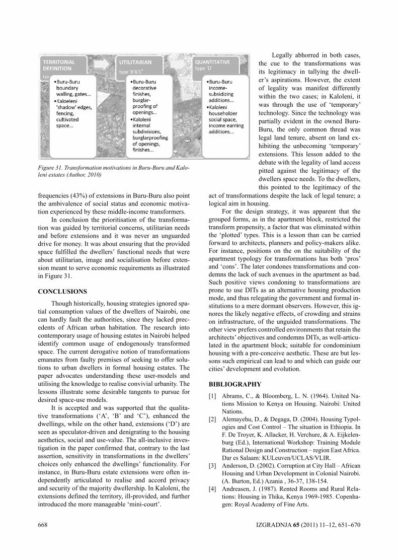
668 IZGRADNJA 65 (2011) 11–12, 651–670
frequencies (43%) of extensions in Buru-Buru also point the ambivalence of social status and economic motiva-tion experienced by these middle-income transformers.
In conclusion the prioritisation of the transforma-tion was guided by territorial concerns, utilitarian needs and before extensions and it was never an unguarded drive for money. It was about ensuring that the provided space fulfilled the dwellers’ functional needs that were about utilitarian, image and socialisation before exten-sion meant to serve economic requirements as illustrated in Figure 31.
cONclUSIONS
Though historically, housing strategies ignored spa-tial consumption values of the dwellers of Nairobi, one can hardly fault the authorities, since they lacked prec-edents of African urban habitation. The research into contemporary usage of housing estates in Nairobi helped identify common usage of endogenously transformed space. The current derogative notion of transformations emanates from faulty premises of seeking to offer solu-tions to urban dwellers in formal housing estates. The paper advocates understanding these user-models and utilising the knowledge to realise convivial urbanity. The lessons illustrate some desirable tangents to pursue for desired space-use models.
It is accepted and was supported that the qualita-tive transformations (‘A’, ‘B’ and ‘C’), enhanced the dwellings, while on the other hand, extensions (‘D’) are seen as speculator-driven and denigrating to the housing aesthetics, social and use-value. The all-inclusive inves-tigation in the paper confirmed that, contrary to the last assertion, sensitivity in transformations in the dwellers’ choices only enhanced the dwellings’ functionality. For instance, in Buru-Buru estate extensions were often in-dependently articulated to realise and accord privacy and security of the majority dwellership. In Kaloleni, the extensions defined the territory, ill-provided, and further introduced the more manageable ‘mini-court’.
act of transformations despite the lack of legal tenure; a logical aim in housing.
For the design strategy, it was apparent that the grouped forms, as in the apartment block, restricted the transform propensity, a factor that was eliminated within the ‘plotted’ types. This is a lesson than can be carried forward to architects, planners and policy-makers alike. For instance, positions on the on the suitability of the apartment typology for transformations has both ‘pros’ and ‘cons’. The later condones transformations and con-demns the lack of such avenues in the apartment as bad. Such positive views condoning to transformations are prone to use DITs as an alternative housing production mode, and thus relegating the government and formal in-stitutions to a mere dormant observers. However, this ig-nores the likely negative effects, of crowding and strains on infrastructure, of the unguided transformations. The other view prefers controlled environments that retain the architects’ objectives and condemns DITs, as well-articu-lated in the apartment block; suitable for condominium housing with a pre-conceive aesthetic. These are but les-sons such empirical can lead to and which can guide our cities’ development and evolution.
BIBlIOgRAPhy
[1] Abrams, C., & Bloomberg, L. N. (1964). United Na-tions Mission to Kenya on Housing. Nairobi: United Nations.
[2] Alemayehu, D., & Degaga, D. (2004). Housing Typol-ogies and Cost Control – The situation in Ethiopia. In F. De Troyer, K. Allacker, H. Verchure, & A. Eijkelen-burg (Ed.), International Workshop: Training Module Rational Design and Construction – region East Africa. Dar es Salaam: KULeuven/UCLAS/VLIR.
[3] Anderson, D. (2002). Corruption at City Hall – African Housing and Urban Development in Colonial Nairobi. (A. Burton, Ed.) Azania , 36-37, 138-154.
[4] Andreasen, J. (1987). Rented Rooms and Rural Rela-tions: Housing in Thika, Kenya 1969-1985. Copenha-gen: Royal Academy of Fine Arts.
Figure 31. Transformation motivations in Buru-Buru and Kalo-leni estates (Author, 2010)
Legally abhorred in both cases, the cue to the transformations was its legitimacy in tallying the dwell-er’s aspirations. However, the extent of legality was manifest differently within the two cases; in Kaloleni, it was through the use of ‘temporary’ technology. Since the technology was partially evident in the owned Buru-Buru, the only common thread was legal land tenure, absent on land ex-hibiting the unbecoming ‘temporary’ extensions. This lesson added to the debate with the legality of land access pitted against the legitimacy of the dwellers space needs. To the dwellers, this pointed to the legitimacy of the
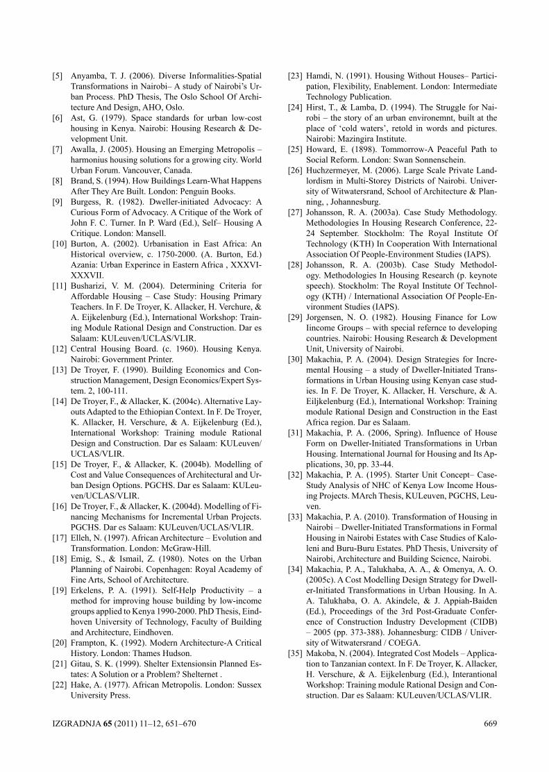
IZGRADNJA 65 (2011) 11–12, 651–670 669
[5] Anyamba, T. J. (2006). Diverse Informalities-Spatial Transformations in Nairobi– A study of Nairobi’s Ur-ban Process. PhD Thesis, The Oslo School Of Archi-tecture And Design, AHO, Oslo.
[6] Ast, G. (1979). Space standards for urban low-cost housing in Kenya. Nairobi: Housing Research & De-velopment Unit.
[7] Awalla, J. (2005). Housing an Emerging Metropolis – harmonius housing solutions for a growing city. World Urban Forum. Vancouver, Canada.
[8] Brand, S. (1994). How Buildings Learn-What Happens After They Are Built. London: Penguin Books.
[9] Burgess, R. (1982). Dweller-initiated Advocacy: A Curious Form of Advocacy. A Critique of the Work of John F. C. Turner. In P. Ward (Ed.), Self– Housing A Critique. London: Mansell.
[10] Burton, A. (2002). Urbanisation in East Africa: An Historical overview, c. 1750-2000. (A. Burton, Ed.) Azania: Urban Experince in Eastern Africa , XXXVI-XXXVII.
[11] Busharizi, V. M. (2004). Determining Criteria for Affordable Housing – Case Study: Housing Primary Teachers. In F. De Troyer, K. Allacker, H. Verchure, & A. Eijkelenburg (Ed.), International Workshop: Train-ing Module Rational Design and Construction. Dar es Salaam: KULeuven/UCLAS/VLIR.
[12] Central Housing Board. (c. 1960). Housing Kenya. Nairobi: Government Printer.
[13] De Troyer, F. (1990). Building Economics and Con-struction Management, Design Economics/Expert Sys-tem. 2, 100-111.
[14] De Troyer, F., & Allacker, K. (2004c). Alternative Lay-outs Adapted to the Ethiopian Context. In F. De Troyer, K. Allacker, H. Verschure, & A. Eijkelenburg (Ed.), International Workshop: Training module Rational Design and Construction. Dar es Salaam: KULeuven/UCLAS/VLIR.
[15] De Troyer, F., & Allacker, K. (2004b). Modelling of Cost and Value Consequences of Architectural and Ur-ban Design Options. PGCHS. Dar es Salaam: KULeu-ven/UCLAS/VLIR.
[16] De Troyer, F., & Allacker, K. (2004d). Modelling of Fi-nancing Mechanisms for Incremental Urban Projects. PGCHS. Dar es Salaam: KULeuven/UCLAS/VLIR.
[17] Elleh, N. (1997). African Architecture – Evolution and Transformation. London: McGraw-Hill.
[18] Emig, S., & Ismail, Z. (1980). Notes on the Urban Planning of Nairobi. Copenhagen: Royal Academy of Fine Arts, School of Architecture.
[19] Erkelens, P. A. (1991). Self-Help Productivity – a method for improving house building by low-income groups applied to Kenya 1990-2000. PhD Thesis, Eind-hoven University of Technology, Faculty of Building and Architecture, Eindhoven.
[20] Frampton, K. (1992). Modern Architecture-A Critical History. London: Thames Hudson.
[21] Gitau, S. K. (1999). Shelter Extensionsin Planned Es-tates: A Solution or a Problem? Shelternet .
[22] Hake, A. (1977). African Metropolis. London: Sussex University Press.
[23] Hamdi, N. (1991). Housing Without Houses– Partici-pation, Flexibility, Enablement. London: Intermediate Technology Publication.
[24] Hirst, T., & Lamba, D. (1994). The Struggle for Nai-robi – the story of an urban environemnt, built at the place of ‘cold waters’, retold in words and pictures. Nairobi: Mazingira Institute.
[25] Howard, E. (1898). Tommorrow-A Peaceful Path to Social Reform. London: Swan Sonnenschein.
[26] Huchzermeyer, M. (2006). Large Scale Private Land-lordism in Multi-Storey Districts of Nairobi. Univer-sity of Witwatersrand, School of Architecture & Plan-ning, , Johannesburg.
[27] Johansson, R. A. (2003a). Case Study Methodology. Methodologies In Housing Research Conference, 22-24 September. Stockholm: The Royal Institute Of Technology (KTH) In Cooperation With International Association Of People-Environment Studies (IAPS).
[28] Johansson, R. A. (2003b). Case Study Methodol-ogy. Methodologies In Housing Research (p. keynote speech). Stockholm: The Royal Institute Of Technol-ogy (KTH) / International Association Of People-En-vironment Studies (IAPS).
[29] Jorgensen, N. O. (1982). Housing Finance for Low Iincome Groups – with special refernce to developing countries. Nairobi: Housing Research & Development Unit, University of Nairobi.
[30] Makachia, P. A. (2004). Design Strategies for Incre-mental Housing – a study of Dweller-Initiated Trans-formations in Urban Housing using Kenyan case stud-ies. In F. De Troyer, K. Allacker, H. Verschure, & A. Eiljkelenburg (Ed.), International Workshop: Training module Rational Design and Construction in the East Africa region. Dar es Salaam.
[31] Makachia, P. A. (2006, Spring). Influence of House Form on Dweller-Initiated Transformations in Urban Housing. International Journal for Housing and Its Ap-plications, 30, pp. 33-44.
[32] Makachia, P. A. (1995). Starter Unit Concept– Case-Study Analysis of NHC of Kenya Low Income Hous-ing Projects. MArch Thesis, KULeuven, PGCHS, Leu-ven.
[33] Makachia, P. A. (2010). Transformation of Housing in Nairobi – Dweller-Initiated Transformations in Formal Housing in Nairobi Estates with Case Studies of Kalo-leni and Buru-Buru Estates. PhD Thesis, University of Nairobi, Architecture and Building Science, Nairobi.
[34] Makachia, P. A., Talukhaba, A. A., & Omenya, A. O. (2005c). A Cost Modelling Design Strategy for Dwell-er-Initiated Transformations in Urban Housing. In A. A. Talukhaba, O. A. Akindele, & J. Appiah-Baiden (Ed.), Proceedings of the 3rd Post-Graduate Confer-ence of Construction Industry Development (CIDB) – 2005 (pp. 373-388). Johannesburg: CIDB / Univer-sity of Witwatersrand / COEGA.
[35] Makoba, N. (2004). Integrated Cost Models – Applica-tion to Tanzanian context. In F. De Troyer, K. Allacker, H. Verschure, & A. Eijkelenburg (Ed.), Interantional Workshop: Training module Rational Design and Con-struction. Dar es Salaam: KULeuven/UCLAS/VLIR.
670 IZGRADNJA 65 (2011) 11–12, 651–670
[36] Menezes, L. (1978). Buru-Buru – a social survey. Nai-robi: Mutiso Menezes International.
[37] Mortimer, C. (1946). Foreward. In G. Oglivie, The Housing Of Africans in the Urban Areas of Kenya (pp. ff1-ff2). Nairobi: The Kenya Information Office.
[38] Mwangi, I. K. (1997). The nature of rental housing in Kenya. Environment and Urbanisation , 9 (2), 141-160.
[39] (c.1950). NAIROBI -A Jubilee History 1900-1950. Nairobi.
[40] Nairobi Area Town Planning Authority. (1927). Ex-planatory Memorandum. Nairobi.
[41] Nairobi Urban Study Group. (1973). Nairobi – Metro-politan Growth Strategy. Nairobi: Nairobi City Coun-cil.
[42] Napier, M. (2002). Core housing, enablement and ur-ban poverty – The consolidation paths of household’s living in two South African settlements. University of Newcastle upon Tyne, CARDO, United Kingdom.
[43] Nevanlinna, A. K. (1996). Interpreting Nairobi. Hel-sinki.
[44] Newman, O. (1972). Defensible Space-People and De-sign in the Violent City. New York: Macmillan.
[45] Obudho, R. A., & Aduwo, G. O. (1992, February & May). The Nature of the Urbanization Process and Ur-banism in the City of Nairobi, Kenya. (R. A. Obudho, Ed.) African Urban Quarterly , 7 (1 & 2), pp. 50-63.
[46] Ogilvie, G. (1946). The Housing of Africans in the Ur-ban Areas of Kenya. Nairobi: The Kenya Information Office.
[47] Owusu, S. E., & Tipple, A. G. (1995). The Process of Extensions in Kumasi, Ghana. Newcastle upon Tyne: CARDO.
[48] Oxman, R., Herbert, G., & Wachman, A. (1985). Strat-egies for Growth and Staged Building in Housing. Habitat International , 9 (1), 25-31.
[49] Panerai, P., Castex, J., & Depaule, J.-C. (2004). Urban Forms-the death and life of the urban block. Oxford: Architectural Press.
[50] Perrotti, G. (1996). From Self-Help to participative Planning – The arcitect’s role under the Latin Ameri-can experience. Royal Institute of Tecnology, Architec-ture and Town Planning, Stockholm.
[51] Perry, C. A. (1929). The Neighbourhood Unit. Region-al Survey of New York and its Environs , VII, 10-14.
[52] Republic of Kenya. (2010). 2009 Kenya Population & Housing Census. Nairobi: Kenya National Bureau of Statistics (KNBS).
[53] Republic of Kenya. (1987). The Sectional Properties Act. Nairobi: Government Printers.
[54] Riley, E., & Wakely, P. (2005). Communities and Com-munication-Building Urban Partnerships. Rugby, UK: ITDG & DFID.
[55] Shihembetsa, L. U. (1995). User Needs In Urban Low-Income Housing: Towards A Framework for Creating User Responsive Environments in Nairobi, Kenya. Ph.D. Thesis , University Of Newcastle Upon Tyne, CARDO, Newcastle Upon Tyne.
[56] Skotte, H. (2004). Tents in Concrete– What Interna-tionally Funded Housing Does To Support Recovery
in Areas Affected By War; the Case of Bosnia-Herze-govina. Norwegian University of Science and Technol-ogy, Faculty of Architecture and Fine Art, Department of Urban Design and Planning. Trondheim: NTNU.
[57] Slaughter, J. (2004). Master Plans: Designing (Na-tional) Allegories of Urban Space and Metropolitan Subjects for Postcolonial Kenya. Research in African Literatures, 35 (1).
[58] Soja, E. (1968). The Geography of Modernisation in Kenya: A Spatial Analysis of the Social, Economic and Political Change . Syracuse NY: Syracuse University .
[59] Syagga, P. (2003). Integrated, Multi-Sectoral and Sec-toral Urban Development Initiatives in Kenya. DFID. Rugby, UK: ITDG.
[60] Syagga, P. M., & Kiamba, J. M. (1992). Housing the Urban Poor: A case study of Pumwani, Kibera and Dandora Estates in the city of Nairobi. (R. A. Obudho, Ed.) African Urban Quarterly , 7 (1 & 2), 79-88.
[61] Thornton-White, L. W., Anderson, P. R., & Silverman, L. (1948). Nairobi– Master Plan For A Colonial Capi-tal– A Report Prepared For The Municipal Council Of Nairobi. London: His Majesty’s Stationery Office.
[62] Tipple, A. G. (2000). Housing Themselves-User-Initi-ated Transformation of Government-Built Housing in Developing Countries. Liverpool: Liverpool Univer-sity Press,.
[63] Tipple, A. G., & Wilkinson, N. (1987). Are Self-Help Extensions the Way Forward in Multi-Storey Walk-ups? Lessons from Helwan, Egypt. African Urban Quartely, 2 (3), 235-249.
[64] Tipple, A. G., & Wilkinson, N. (1986). Self-Help Transformation of Government Built Flats – The case of Helwan, Egypt. In K. Mathey, Beyond Self-Help Housing (pp. 283-301). Mansell.
[65] Tipple, A. G., Wilkinson, N., & Nuor, M. (1985). Transformation of Worker’s City Helwan: Multi-Sto-rey Extensions Observed. Open House International, 10 (3), 25-38.
[66] Tipple, A. (1999). Transforming Government-Built Housing: Lessons from developing Countries. Journal of Urban Technology, 6 (3), 17-35.
[67] Turner, J. F. (1969). Alternatitve Interpretations and Alternative Policies. USAID.
[68] Turner, J. F. (1972). Housing as a Verb. In J. T. Fichter (Ed.), Freedom to Build. New York: Macmillan.
[69] Turner, J. F. (1977). Housing by the People – Towards Autonomy in Building Environments. New York: Pan-theon.
[70] Tzonis, A. (1976). Forum. In The Name Of the Peo-ple– The Development of Contemporary Populist Movement in Architecture, XXV (3 ), pp. 5-9 & 27-33.
[71] Unwin, R. (1902). Town Planning in Practice, An In-troduction to the Art o f Designing Cities and Sub-urbs. London: Fisher Unwin.
[72] Yin, R. K. (2003). Case Study – Design and Research Methods. London: Sage Publications.
IZGRADNJA 65 (2011) 11–12, 671–680 671
СУНЧЕВА ЕНЕРГИЈА ЗА ДЕЦУ: ПРОЈЕКАТ ДОГРАДЊЕ О.Ш. „ДРАГОЈЛО ДУДИЋ” У БЕОГРАДУSOLAR ENERGY FOR kIDS: DESIGN OF PRIMARY SCHOOL „DRAGOJLO DUDIĆ” UPGRADE IN BELGRADE
UDK: 727.112(497.11) Originalni naučni rad
Доц. др Љиљана АЛЕКСИћ, дипл. инж. арх. Др Весна КОСОРИћ, дипл. инж. арх.
РЕЗИМЕОвај рад представља пројектантске концепте и стратегије примењене у
пројектовању доградње Основне школе „Драгојло Дудић“ у Београду и показује добити које би се могле постићи „пасивним“ и „активним“ коришћењем сунчеве енергије. Пројекат има за циљ да демонстрира високог перформанса, енергетски ефикасну и одрживу архитектуру. Новопројектована зграда школе је волуметријски пројектована у складу са биоклиматским принципима, и брижљиво је угњездена у контекст окружења тако да максимално користи његове предности сa једне стране, и превазилази његова ограничења са друге стране, креирајући интензивну, позитивну међусобну интерактивну везу са њим. Каскадно позиционирани и југо-западно оријентисани блокови зграде, адекватно уклопљени у веома нагнут терен са око 20 m висинске разлике, омогућавају функционално добру организацију и високо квалитетни комфор пројектованих простора (10 учионица, 2 вишенаменске учионице, отворене терасе, зборница, кухињско постројење, помоћни простори). Здравље и комфор ученика и других корисника школе су сматрани за високе приоритете током интегрисаног процеса пројектовања. Полутранспарентни монокристални фотонапонски модули су интегрисани као покретни соларни застори, на југо-западној фасади, побољшавајући термички и визуелни комфор и дајући интересантне естетске ефекте споља и у унутрашњости зграде, и стварајући идентитет школе оријентисан ка одрживом развоју, као и подижући свест о уштедама енергије и коришћењу обновљивих извора енергије. Овај пројекат школе тежи да се брине истовремено о корисницима простора и окружењу, и да мотивише и инспирише људе да се брину о свету око себе.
Кључне речи: здравље и комфор, интегрисани процес пројектовања, интегрисани фотонапонски системи, контекстуализам, сунчева енергија, школа.
SUMMARYThis paper presents design concepts and strategies applied in designing of Primary school
„Dragojlo Dudić“ upgrade in Belgrade and shows the benefits that could be achieved by both „passive“ and „active“ solar energy utilization. The project aims to demonstrate high perfor-mance, energy efficient and sustainable architecture. The new designed building of the school is volumetrically designed according to bioclimatic approaches, and it is carefully nested in the context to maximally use its advantages on one side, and to overcome its limitations on other side, creating intensive, positive mutual interaction with it. The cascade positioned and south-west oriented building’s blocks, adequately fitted in the steeply inclined terrain with ca. 20 m height difference, are enabling functionally good organization and high-quality comfort of designed spaces (10 classrooms, 2 multi-purpose classrooms, open terraces, office, kitchen facility, auxiliary spaces). The health and comfort of pupils and other occupants of the school
Adresa autora: Грађевински факултет, Универзитет у Новом Саду, 24000 Суботица, Kozaračka 2aE-mail: [email protected] 14, CH-4600 Olten, SwitzerlandE-mail: [email protected]
672 IZGRADNJA 65 (2011) 11–12, 671–680
1. УВОД
Основна школа „Драгојло Дудић“ се налази у Булевару краља Александра, у делу Београда који припада насељу Мали Мокри Луг. Постојећа шко-ла, радом у две смене, задовољава тренутне потребе самог насеља као и потребе околних насеља – што значи да реалне потребе превазилазе просторне ка-пацитете постојеће школе и наглашавају потребу за доградњом која би задовољила повећане потребе и услове једносменског рада.
Школско двориште је пространо и лепо орга-низовано, са денивелацијом према Булевару краља Александра, обезбеђено потпорним зидом и сигур-носном оградом. Унутрашње двориште, смештено иза зграде школе, једним делом се користи као „школско игралиште“ за кошарку, одбојку и рукомет, а већи део дворишта се налази на нагнутом терену, покри-вен ниским растињем и нижим листопадним дрвећем и не користи се. Нагиб терена асоцира на каскадно пружање објекта и „сафдијевски“ моделиране струк-туре.
Новопројектовани објекат је предвиђен за децу од I до IV разреда. Каскадно пројектовани блокови зграде су разуђено постављени, тако да остављају зе-лени простор између, који би могао да се користи за учење и боравак на отвореном, као и за игру. Фор-ма објекта и повезаност са непосредним окружењем одсликавају принципе контекстуализма. У раду су описани основни концепти и стратегије коришћени у оквиру интегрисаног процеса пројектовања који је примењен при пројектовању доградње школе. Зграда је пројектована у складу са биоклиматским принци-пима, са посебним вођењем рачуна о комфору учени-ка и других корисника. У раду је детаљније приказа-но планирано коришћење сунчеве енергије.
2. О.Ш. „ДРАГОЈЛО ДУДИћ“ – ПОСТОЈЕћЕ СТАњЕ
2.1. Објекат постојеће школе
Школа има тренутно 36 одељења, од тога 19 одељења нижих разреда, од I до IV, и 17 одељења виших разреда, од V до VIII. Постојећа зграда О.Ш „Драгојло Дудић“ поседује 19 учионица које подми-рују потребе 36 одељења, али са радом у две смене, као једином могућом организацијом, где су за спорт-ске активности и многобројне секције, једини могући термини после завршене наставе тј. после 20h. То на-
were considered as high priorities during the design process. Semi-transparent monocrystalline Photovoltaic (PV) modules are integrated as movable solar blinds, on south-western facade im-proving the thermal and visual comfort and giving interesting aesthetic effects from both outside and inside of the building, and creating sustainability oriented identity of the school and rising awareness for energy savings and renewable energy sources (RESs) utilization. The design of the school efforts to present care for both the occupants and the context, and to motivate and inspire people to take care for the world around.
Key words: health & comfort, integrated design process (IDP), building integrated photo-voltaics (BIPV), environmental contextualism, solar energy, school.
1. INTRODUcTION
The primary school “Dragojlo Dudić” is situated in Boulevard of king Aleksandar, in the part of Belgrade which belongs to the settlement Mali Mokri Lug. The existing primary school, working in two shifts, meet the present requirements of the settlement and the require-ments of the surrounding settlements as well – which means that the real demand are exceeding spatial capaci-ties of the existing school and are emphasizing the de-mand for the school upgrade which will meet expanded demands and the conditions of the work in only one shift.
The schoolyard is wide and well organized, with the denivelation toward Boulevard of king Aleksandar, provided with retaining wall and safety fence. The inter-nal courtyard, situated below the school, is on one side used as „school playground” for basketball, volley-ball and handball, but the biggest part is located on sloping terrain, covered with the low vegetation and lower de-ciduous trees and it is not used currently. The slope of the terrain associates on cascade insertion of the building and on „safdie-stic” shaped structures.
The designed building is planned for the children from 1st to 4th grade. The cascade designed building blocks are distributed situated, so that they leave green area between, which could be used for studying and spending time outdoor, and for the playing as well. The building form and the connection with the close environ-ment present the principles of the environmental contex-tualism. The main concepts and strategies used inside IDP which are applied in the school upgrade design are presented in this paper. The building is designed accord-ing to the bioclimatic principles, with special taking care of the comfort of the pupils and other users. The planned solar energy utilization is more in dept presented in the paper.
2. PRIMARy SchOOl „DRAgOjlO DUDIć“ – ThE ExISTINg STATE
2.1. The building of the existing school
The school currently has 36 classes: 19 lower grades, from 1st to 4th grade, and 17 higher classes, from 5th to 8th grade. The building of the existing primary school „Dragojlo Dudić” have 19 classrooms which are meeting the need of 36 classes, but with working in two shifts, as the only one possible organization, where the only pos-sible terms for the sport activities and numerous facul-
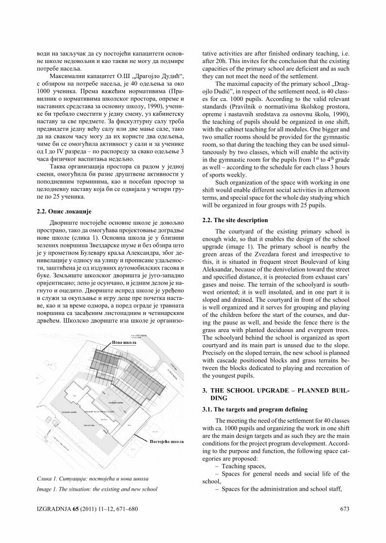
IZGRADNJA 65 (2011) 11–12, 671–680 673
води на закључак да су постојећи капацитети основ-не школе недовољни и као такви не могу да подмире потребе насеља.
Максимални капацитет О.Ш „Драгојло Дудић“, с обзиром на потребе насеља, је 40 одељења за око 1000 ученика. Према важећим нормативима (Пра-вилник о нормативима школског простора, опреме и наставних средстава за основну школу, 1990), учени-ке би требало сместити у једну смену, уз кабинетску наставу за све предмете. За фискултурну салу треба предвидети једну већу салу или две мање сале, тако да на сваком часу могу да их користе два одељења, чиме би се омогућила активност у сали и за ученике од I до IV разреда – по распореду за свако одељење 3 часа физичког васпитања недељно.
Таква организација простора са радом у једној смени, омогућила би разне друштвене активности у поподневним терминима, као и посебан простор за целодневну наставу која би се одвијала у четири гру-пе по 25 ученика.
2.2. Опис локације
Двориште постојеће основне школе је довољно пространо, тако да омогућава пројектовање доградње нове школе (слика 1). Основна школа је у близини зелених површина Звездарске шуме и без обзира што је у прометном Булевару краља Александра, због де-нивелације у односу на улицу и прописане удаљенос-ти, заштићена је од издувних аутомобилских гасова и буке. Земљиште школског дворишта је југо-западно оријентисано; лепо је осунчано, и једним делом је на-гнуто и оцедито. Двориште испред школе је уређено и служи за окупљање и игру деце пре почетка наста-ве, као и за време одмора, а поред ограде је травната површина са засађеним листопадним и четинарским дрвећем. Школско двориште иза школе је организо-
tative activities are after finished ordinary teaching, i.e. after 20h. This invites for the conclusion that the existing capacities of the primary school are deficient and as such they can not meet the need of the settlement.
The maximal capacity of the primary school „Drag-ojlo Dudić”, in respect of the settlement need, is 40 class-es for ca. 1000 pupils. According to the valid relevant standards (Pravilnik о normativima školskog prostora, opreme i nastavnih sredstava za osnovnu školu, 1990), the teaching of pupils should be organized in one shift, with the cabinet teaching for all modules. One bigger and two smaller rooms should be provided for the gymnastic room, so that during the teaching they can be used simul-taneously by two classes, which will enable the activity in the gymnastic room for the pupils from 1st to 4th grade as well – according to the schedule for each class 3 hours of sports weekly.
Such organization of the space with working in one shift would enable different social activities in afternoon terms, and special space for the whole day studying which will be organized in four groups with 25 pupils.
2.2. The site description
The courtyard of the existing primary school is enough wide, so that it enables the design of the school upgrade (image 1). The primary school is nearby the green areas of the Zvezdara forest and irrespective to this, it is situated in frequent street Boulevard of king Aleksandar, because of the denivelation toward the street and specified distance, it is protected from exhaust cars’ gases and noise. The terrain of the schoolyard is south-west oriented; it is well insolated, and in one part it is sloped and drained. The courtyard in front of the school is well organized and it serves for grouping and playing of the children before the start of the courses, and dur-ing the pause as well, and beside the fence there is the grass area with planted deciduous and evergreen trees. The schoolyard behind the school is organized as sport courtyard and its main part is unused due to the slope. Precisely on the sloped terrain, the new school is planned with cascade positioned blocks and grass terrains be-tween the blocks dedicated to playing and recreation of the youngest pupils.
3. ThE SchOOl UPgRADE – PlANNED BUIl-DINg
3.1. The targets and program defining
The meeting the need of the settlement for 40 classes with ca. 1000 pupils and organizing the work in one shift are the main design targets and as such they are the main conditions for the project program development. Accord-ing to the purpose and function, the following space cat-egories are proposed:
– Teaching spaces,– Spaces for general needs and social life of the
school,– Spaces for the administration and school staff,
Слика 1. Ситуација: постојећа и нова школа
Image 1. The situation: the existing and new school
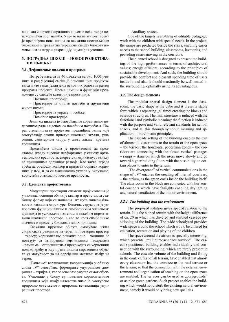
674 IZGRADNJA 65 (2011) 11–12, 671–680
вано као спортско игралиште и његов већи део је не-искоришћен због нагиба. Управо на нагнутом терену је предвиђена нова школа са каскадно постављеним блоковима и травнатим теренима између блокова на-мењеним за игру и рекреацију најмлађих ученика.
3. ДОГРАДњА ШКОЛЕ – НОВОПРОЈЕКТОВА-НИ ОбЈЕКАТ
3.1. Дефинисање циљева и програма
Потребе насеља за 40 одељења са око 1000 уче-ника и рад у једној смени је основни циљ пројекто-вања и као такав један је од основних услова за развој програма пројекта. Према намени и функцији пред-ложене су следеће категорије просторија:
– Наставне просторије,– Просторије за опште потребе и друштвени
живот школе,– Просторије за управу и особље,– Помоћне просторије.Један од циљева је омогућавање корективног пе-
дагошког рада са децом са посебним потребама. По-ред степеништа су пројектом предвиђене рампе које омогућавају лакши приступ школској згради, учи-оници, санитарном чвору, у циљу лакшег кретања ходницима.
Предвиђена школа je пројектована да пред-ставља зграду високог перформанса у смислу архи-тектонских вредности, енергетски ефикасну, у складу са принципима одрживог развоја. Као таква, зграда треба да обезбеди комфор и пријатан боравак корис-ника у њој, и да се максимално уклапа у окружење, користећи оптимално његове предности.
3.2. Елементи пројектовања
Модуларни просторни елемент пројектовања је учионица, основни облик је квадар и представља ста-билну форму која се понавља „n“ пута чинећи бло-кове и каскадне структуре. Коначна структура је ус-ловљена функционалним и симболичким значењем: функција је условљена наменом и важећим нормати-вима школског простора, а све то кроз симболичко значење и примену биоклиматских принципа.
Каскадно пружање објекта омогућава излаз скоро сваке учионице на терен или отворен простор – терасу; хоризонталне пешачке зоне – ходници се повезују са затвореним вертикалним пасарелама – рампама – степеништима преко којих се корисници полако крећу и иду према вишим спратовима објек-та уз могућност да на одређеним местима изађу на терен.
„Рачвање“ вертикалних комуникација у облику слова „V“ омогућава формирање унутрашњег дво-ришта – атријума, као зелене оазе унутар самог објек-та. Учионице у блоку су повезане хоризонталним ходницима који имају надсветла чиме је омогућено природно осветљење и природна вентилација унут-рашњег простора.
– Auxiliary spaces.One of the targets is enabling of editable pedagogic
work with the children with special needs. In the project, the ramps are predicted beside the stairs, enabling easier access to the school building, classrooms, lavatories, and providing easier moving in the corridors.
The planned school is designed to present the build-ing of the high performances in terms of architectural values; energy efficient, according to the principles of sustainable development. And such, the building should provide the comfort and pleasant spending time of users inside it, and also it should maximally be well nested in the surrounding, optimally using its advantageous.
3.2. The design elements
The modular spatial design element is the class-room, the basic shape is the cube and it presents stable form which is repeating „n” times creating the blocks and cascade structures. The final structure is induced with the functional and symbolic meaning: the function is induced with the purpose and valid relevant standards for school spaces, and all this through symbolic meaning and ap-plication of bioclimatic principles.
The cascade setting of the building enables the exit of almost all classrooms to the terrain or the open space – the terrace; the horizontal pedestrian zones – the cor-ridors are connecting with the closed vertical passages – ramps – stairs on which the users move slowly and go toward higher building floors with the possibility on cer-tain places to enter to the terrain.
„The divergence” of vertical communications in the shape of „V” enables the creating of internal courtyard – the atrium, as the green oasis inside the building itself. The classrooms in the block are connected with horizon-tal corridors which have fanlights enabling daylighting and natural ventilation of the indoor environment.
3.2.1. The building and the environment
The proposed solution gives special relation to the terrain. It is the sloped terrain with the height difference of ca. 20 m which has directed and enabled cascade po-sitioning of the building. The wide schoolyard provides wide space around the school which would be utilized for education, recreation and playing of the children.
The space around the atrium is specially interesting, which presents „multipurpose space outdoor”. The cas-cade positioned building enables individuality and con-nection with the surrounding, which are rarely present in schools. The cascade volume of the building and fitting in the context, first of all terrain, have enabled that almost every classroom has the entrance to the roof terrace or the terrain, so that the connection with the external envi-ronment and organization of teaching on the open space are enabled. The terraces can be used as „playgrounds” or as nice green gardens. Such project enables the build-ing which would not disturb the existing natural environ-ment, namely it would only bring new qualities.
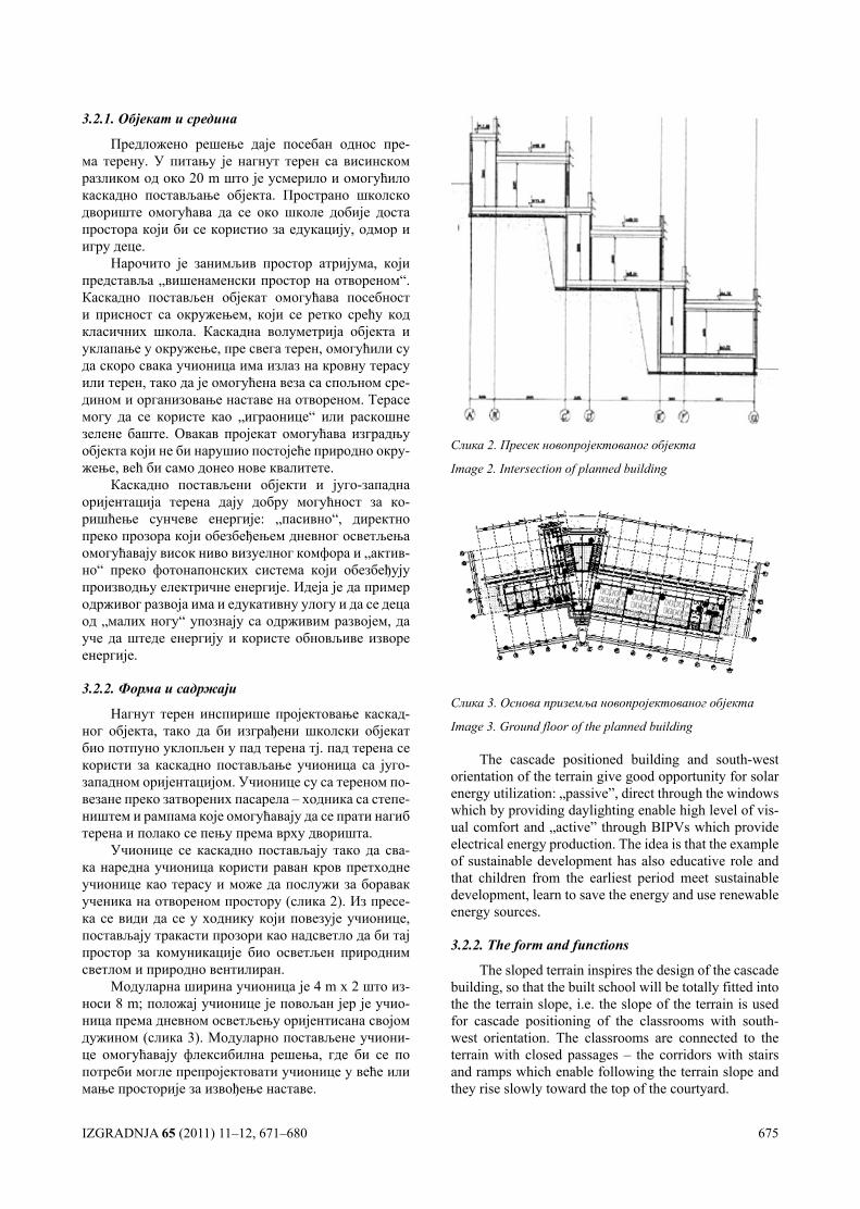
IZGRADNJA 65 (2011) 11–12, 671–680 675
3.2.1. Објекат и средина
Предложено решење даје посебан однос пре-ма терену. У питању је нагнут терен са висинском разликом од око 20 m што је усмерило и омогућило каскадно постављање објекта. Пространо школско двориште омогућава да се око школе добије доста простора који би се користио за едукацију, одмор и игру деце.
Нарочито је занимљив простор атријума, који представља „вишенаменски простор на отвореном“. Каскадно постављен објекат омогућава посебност и присност са окружењем, који се ретко срећу код класичних школа. Каскадна волуметрија објекта и уклапање у окружење, пре свега терен, омогућили су да скоро свака учионица има излаз на кровну терасу или терен, тако да је омогућена веза са спољном сре-дином и организовање наставе на отвореном. Терасе могу да се користе као „играонице“ или раскошне зелене баште. Овакав пројекат омогућава изградњу објекта који не би нарушио постојеће природно окру-жење, већ би само донео нове квалитете.
Каскадно постављени објекти и југо-западна оријентација терена дају добру могућност за ко-ришћење сунчеве енергије: „пасивно“, директно преко прозора који обезбеђењем дневног осветљења омогућавају висок ниво визуелног комфора и „актив-но“ преко фотонапонских система који обезбеђују производњу електричне енергије. Идеја је да пример одрживог развоја има и едукативну улогу и да се деца од „малих ногу“ упознају са одрживим развојем, да уче да штеде енергију и користе обновљиве изворе енергије.
3.2.2. Форма и садржаји
Нагнут терен инспирише пројектовање каскад-ног објекта, тако да би изграђени школски објекат био потпуно уклопљен у пад терена тј. пад терена се користи за каскадно постављање учионица са југо-западном оријентацијом. Учионице су са тереном по-везане преко затворених пасарела – ходника са степе-ништем и рампама које омогућавају да се прати нагиб терена и полако се пењу према врху дворишта.
Учионице се каскадно постављају тако да сва-ка наредна учионица користи раван кров претходне учионице као терасу и може да послужи за боравак ученика на отвореном простору (слика 2). Из пресе-ка се види да се у ходнику који повезује учионице, постављају тракасти прозори као надсветло да би тај простор за комуникације био осветљен природним светлом и природно вентилиран.
Модуларна ширина учионица је 4 m x 2 што из-носи 8 m; положај учионице је повољан јер је учио-ница према дневном осветљењу оријентисана својом дужином (слика 3). Модуларно постављене учиони-це омогућавају флексибилна решења, где би се по потреби могле препројектовати учионице у веће или мање просторије за извођење наставе.
Слика 2. Пресек новопројектованог објекта
Image 2. Intersection of planned building
Слика 3. Основа приземља новопројектованог објекта
Image 3. Ground floor of the planned building
The cascade positioned building and south-west orientation of the terrain give good opportunity for solar energy utilization: „passive”, direct through the windows which by providing daylighting enable high level of vis-ual comfort and „active” through BIPVs which provide electrical energy production. The idea is that the example of sustainable development has also educative role and that children from the earliest period meet sustainable development, learn to save the energy and use renewable energy sources.
3.2.2. The form and functions
The sloped terrain inspires the design of the cascade building, so that the built school will be totally fitted into the the terrain slope, i.e. the slope of the terrain is used for cascade positioning of the classrooms with south-west orientation. The classrooms are connected to the terrain with closed passages – the corridors with stairs and ramps which enable following the terrain slope and they rise slowly toward the top of the courtyard.
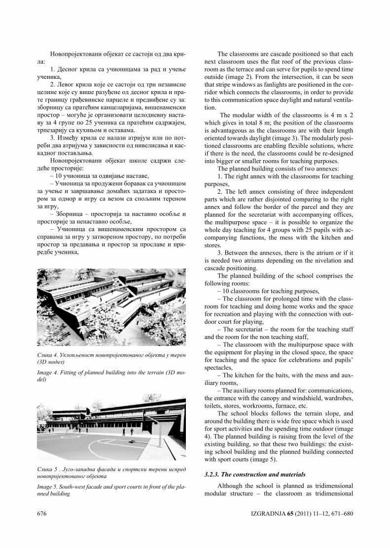
676 IZGRADNJA 65 (2011) 11–12, 671–680
Новопројектовани објекат се састоји од два кри-ла:
1. Десног крила са учионицама за рад и учење ученика,
2. Левог крила које се састоји од три независне целине које су више разуђене од десног крила и пра-те границу грађевинске парцеле и предвиђене су за: зборницу са пратећим канцеларијама, вишенаменски простор – могуће је организовати целодневну наста-ву за 4 групе по 25 ученика са пратећим садржајем, трпезарију са кухињом и оставама.
3. Између крила се налази атријум или по пот-реби два атријума у зависности од нивелисања и кас-кадног постављања.
Новопројектовани објекат школе садржи сле-деће просторије:
– 10 учионица за одвијање наставе,– Учионица за продужени боравак са учионицом
за учење и завршавање домаћих задатака и просто-ром за одмор и игру са везом са спољним тереном за игру,
– Зборница – просторија за наставно особље и просторије за ненаставно особље,
– Учионица са вишенаменским простором са справама за игру у затвореном простору, по потреби простор за предавања и простор за прославе и при-редбе ученика,
The classrooms are cascade positioned so that each next classroom uses the flat roof of the previous class-room as the terrace and can serve for pupils to spend time outside (image 2). From the intersection, it can be seen that stripe windows as fanlights are positioned in the cor-ridor which connects the classrooms, in order to provide to this communication space daylight and natural ventila-tion.
The modular width of the classrooms is 4 m x 2 which gives in total 8 m; the position of the classrooms is advantageous as the classrooms are with their length oriented towards daylight (image 3). The modularly posi-tioned classrooms are enabling flexible solutions, where if there is the need, the classrooms could be re-designed into bigger or smaller rooms for teaching purposes.
The planned building consists of two annexes: 1. The right annex with the classrooms for teaching
purposes, 2. The left annex consisting of three independent
parts which are rather disjointed comparing to the right annex and follow the border of the parcel and they are planned for the secretariat with accompanying offices, the multipurpose space – it is possible to organize the whole day teaching for 4 groups with 25 pupils with ac-companying functions, the mess with the kitchen and stores.
3. Between the annexes, there is the atrium or if it is needed two atriums depending on the nivelation and cascade positioning.
The planned building of the school comprises the following rooms:
– 10 classrooms for teaching purposes, – The classroom for prolonged time with the class-
room for teaching and doing home works and the space for recreation and playing with the connection with out-door court for playing,
– The secretariat – the room for the teaching staff and the room for the non teaching staff,
– The classroom with the multipurpose space with the equipment for playing in the closed space, the space for teaching and the space for celebrations and pupils’ spectacles,
– The kitchen for the baits, with the mess and aux-iliary rooms,
– The auxiliary rooms planned for: communications, the entrance with the canopy and windshield, wardrobes, toilets, stores, workrooms, furnace, etc.
The school blocks follows the terrain slope, and around the building there is wide free space which is used for sport activities and the spending time outdoor (image 4). The planned building is raising from the level of the existing building, so that these two buildings: the exist-ing school building and the planned building connected with sport courts (image 5).
3.2.3. The construction and materials
Although the school is planned as tridimensional modular structure – the classroom as tridimensional
Слика 4. Уклопљеност новопројектованог објекта у терен (3D модел)
Image 4. Fitting of planned building into the terrain (3D mo-del)
Слика 5 . Југо-западна фасада и спортски терени испред новопројектованог објекта
Image 5. South-west facade and sport courts in front of the pla-nned building
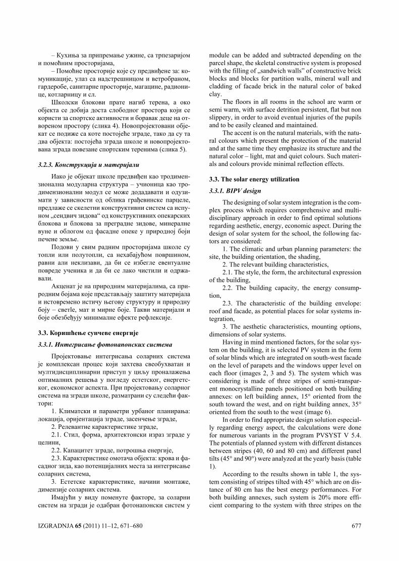
IZGRADNJA 65 (2011) 11–12, 671–680 677
– Кухиња за припремање ужине, са трпезаријом и помоћним просторијама,
– Помоћне просторије које су предвиђене за: ко-муникације, улаз са надстрешницом и ветробраном, гардеробе, санитарне просторије, магацине, радиони-це, котларницу и сл.
Школски блокови прате нагиб терена, a око објекта се добија доста слободног простора који се користи за спортске активности и боравак деце на от-вореном простору (слика 4). Новопројектовани обје-кат се подиже са коте постојеће зграде, тако да су та два објекта: постојећа зграда школе и новопројекто-вана зграда повезане спортским теренима (слика 5).
3.2.3. Конструкција и материјали
Иако је објекат школе предвиђен као тродимен-зионална модуларна структура – учионица као тро-димензионални модул се може додадавати и одузи-мати у зависности од облика грађевинске парцеле, предлаже се скелетни конструктивни систем са испу-ном „сендвич зидова“ од конструктивних опекарских блокова и блокова за преградне зидове, минералне вуне и облогом од фасадне опеке у природној боји печене земље.
Подови у свим радним просторијама школе су топли или полутопли, са нехабајућом површином, равни али неклизави, да би се избегле евентуалне повреде ученика и да би се лако чистили и одржа-вали.
Акценат је на природним материјалима, са при-родним бојама које представљају заштиту материјала и истовремено истичу његову структуру и природну боју – светlе, мат и мирне боје. Такви материјали и боје обезбеђују минималне ефекте рефлексије.
3.3. Коришћење сунчеве енергије
3.3.1. Интегрисање фотонапонских система
Пројектовање интегрисања соларних система је комплексан процес који захтева свеобухватан и мултидисциплинарни приступ у циљу проналажења оптималних решења у погледу естетског, енергетс-ког, економског аспекта. При пројектовању соларног система на згради школе, разматрани су следећи фак-тори:
1. Климатски и параметри урбаног планирања: локација, оријентација зграде, засенчење зграде,
2. Релевантне карактеристике зграде,2.1. Стил, форма, архитектонски израз зграде у
целини,2.2. Капацитет зграде, потрошња енергије,2.3. Карактеристике омотача објекта: крова и фа-
садног зида, као потенцијалних места за интегрисање соларних система,
3. Естетске карактеристике, начини монтаже, димензије соларних система.
Имајући у виду поменуте факторе, за соларни систем на згради је одабран фотонапонски систем у
module can be added and subtracted depending on the parcel shape, the skeletal constructive system is proposed with the filling of „sandwich walls” of constructive brick blocks and blocks for partition walls, mineral wall and cladding of facade brick in the natural color of baked clay.
The floors in all rooms in the school are warm or semi warm, with surface detrition persistent, flat but non slippery, in order to avoid eventual injuries of the pupils and to be easily cleaned and maintained.
The accent is on the natural materials, with the natu-ral colours which present the protection of the material and at the same time they emphasize its structure and the natural color – light, mat and quiet colours. Such materi-als and colours provide minimal reflection effects.
3.3. The solar energy utilization
3.3.1. BIPV design
The designing of solar system integration is the com-plex process which requires comprehensive and multi-disciplinary approach in order to find optimal solutions regarding aesthetic, energy, economic aspect. During the design of solar system for the school, the following fac-tors are considered:
1. The climatic and urban planning parameters: the site, the building orientation, the shading,
2. The relevant building characteristics, 2.1. The style, the form, the architectural expression
of the building, 2.2. The building capacity, the energy consump-
tion, 2.3. The characteristic of the building envelope:
roof and facade, as potential places for solar systems in-tegration,
3. The aesthetic characteristics, mounting options, dimensions of solar systems.
Having in mind mentioned factors, for the solar sys-tem on the building, it is selected PV system in the form of solar blinds which are integrated on south-west facade on the level of parapets and the windows upper level on each floor (images 2, 3 and 5). The system which was considering is made of three stripes of semi-transpar-ent monocrystalline panels positioned on both building annexes: on left building annex, 15° oriented from the south toward the west, and on right building annex, 35° oriented from the south to the west (image 6).
In order to find appropriate design solution especial-ly regarding energy aspect, the calculations were done for numerous variants in the program PVSYST V 5.4. The potentials of planned system with different distances between stripes (40, 60 and 80 cm) and different panel tilts (45° and 90°) were analyzed at the yearly basis (table 1).
According to the results shown in table 1, the sys-tem consisting of stripes tilted with 45° which are on dis-tance of 80 cm has the best energy performances. For both building annexes, such system is 20% more effi-cient comparing to the system with three stripes on the
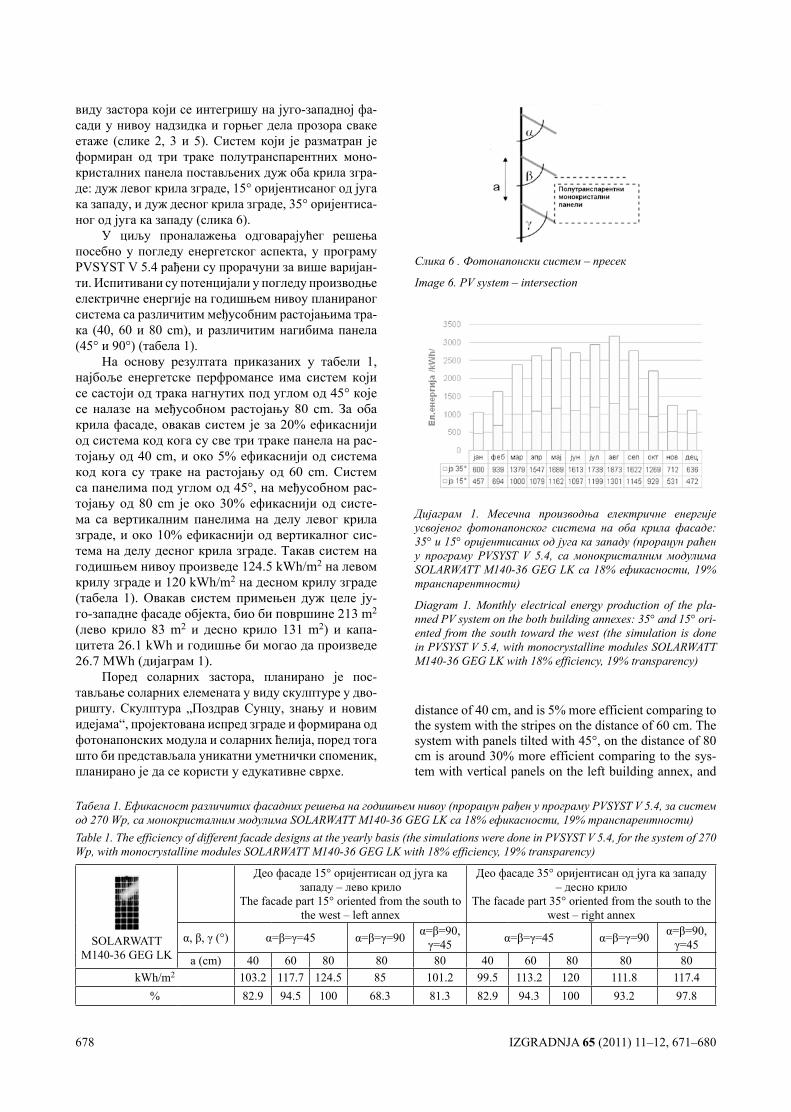
678 IZGRADNJA 65 (2011) 11–12, 671–680
виду застора који се интегришу на југо-западној фа-сади у нивоу надзидка и горњег дела прозора сваке етаже (слике 2, 3 и 5). Систем који је разматран је формиран од три траке полутранспарентних моно-кристалних панела постављених дуж оба крила згра-де: дуж левог крила зграде, 15° оријентисаног од југа ка западу, и дуж десног крила зграде, 35° оријентиса-ног од југа ка западу (слика 6).
У циљу проналажења одговарајућег решења посебно у погледу енергетског аспекта, у програму PVSYST V 5.4 рађени су прорачуни за више варијан-ти. Испитивани су потенцијали у погледу производње електричне енергије на годишњем нивоу планираног система са различитим међусобним растојањима тра-ка (40, 60 и 80 cm), и различитим нагибима панела (45° и 90°) (табела 1).
На основу резултата приказаних у табели 1, најбоље енергетске перфромансе има систем који се састоји од трака нагнутих под углом од 45° које се налазе на међусобном растојању 80 cm. За оба крила фасаде, овакав систем је за 20% ефикаснији од система код кога су све три траке панела на рас-тојању од 40 cm, и око 5% ефикаснији од система код кога су траке на растојању од 60 cm. Систем са панелима под углом од 45°, на међусобном рас-тојању од 80 cm је око 30% ефикаснији од систе-ма са вертикалним панелима на делу левог крила зграде, и око 10% ефикаснији од вертикалног сис-тема на делу десног крила зграде. Такав систем на годишњем нивоу произведе 124.5 kWh/m2 на левом крилу зграде и 120 kWh/m2 на десном крилу зграде (табела 1). Овакав систем примењен дуж целе ју-го-западне фасаде објекта, био би површине 213 m2 (лево крило 83 m2 и десно крило 131 m2) и капа-цитета 26.1 kWh и годишње би могао да произведе 26.7 МWh (дијаграм 1).
Поред соларних застора, планирано је пос-тављање соларних елемената у виду скулптуре у дво-ришту. Скулптура „Поздрав Сунцу, знању и новим идејама“, пројектована испред зграде и формирана од фотонапонских модула и соларних ћелија, поред тога што би представљала уникатни уметнички споменик, планирано је да се користи у едукативне сврхе.
distance of 40 cm, and is 5% more efficient comparing to the system with the stripes on the distance of 60 cm. The system with panels tilted with 45°, on the distance of 80 cm is around 30% more efficient comparing to the sys-tem with vertical panels on the left building annex, and
Слика 6 . Фотонапонски систем – пресек
Image 6. PV system – intersection
Дијаграм 1. Месечна производња електричне енергије усвојеног фотонапонског система на оба крила фасаде: 35° и 15° оријентисаних од југа ка западу (прорацун раћен у програму PVSYST V 5.4, са монокристалним модулима SOLARWATT M140-36 GEG LK са 18% ефикасности, 19% транспарентности)
Diagram 1. Monthly electrical energy production of the pla-nned PV system on the both building annexes: 35° and 15° ori-ented from the south toward the west (the simulation is done in PVSYST V 5.4, with monocrystalline modules SOLARWATT M140-36 GEG LK with 18% efficiency, 19% transparency)
Табела 1. Ефикасност различитих фасадних решења на годишњем нивоу (прорацун рађен у програму PVSYST V 5.4, за систем од 270 Wp, са монокристалним модулима SOLARWATT M140-36 GEG LK са 18% ефикасности, 19% транспарентности) Table 1. The efficiency of different facade designs at the yearly basis (the simulations were done in PVSYST V 5.4, for the system of 270 Wp, with monocrystalline modules SOLARWATT M140-36 GEG LK with 18% efficiency, 19% transparency)
SOLARWATT M140-36 GEG LK
Део фасаде 15° оријентисан од југа ка западу – лево крило
The facade part 15° oriented from the south to the west – left annex
Део фасаде 35° оријентисан од југа ка западу – десно крило
The facade part 35° oriented from the south to the west – right annex
α, β, γ (°) α=β=γ=45 α=β=γ=90 α=β=90, γ=45 α=β=γ=45 α=β=γ=90 α=β=90,
γ=45а (cm) 40 60 80 80 80 40 60 80 80 80
kWh/m2 103.2 117.7 124.5 85 101.2 99.5 113.2 120 111.8 117.4% 82.9 94.5 100 68.3 81.3 82.9 94.3 100 93.2 97.8
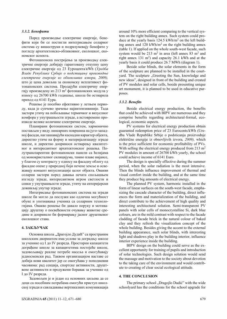
IZGRADNJA 65 (2011) 11–12, 671–680 679
3.3.2. Бенефити
Поред производње електричне енергије, бене-фити који би се постигли интегрисањем соларног система су вишеструки и подразумевају бенефите у погледу архитектонско-обликовног, еколошког, еко-номског аспекта.
Фотонапонска постројења за производњу елек-тричне енергије добијају гарантовану откупну цену електричне енергије од 23 Еуроцента/кWh (Уредба Владе Републике Србије о подстицању производње електричне енергије из обновљивих извора, 2009), што је цена довољна за економску исплативост фо-тонапонских система. Продајући електричну енер-гију произведену из 213 m2 фотонапонских модула у износу од 26700 kWh годишње, школа би остварила приход од 6141 Еура.
Решење је посебно ефективно у летњем перио-ду, када је сунчево зрачење најинтензивиније. Тада застори утичу на побољшање термичког и визуелног комфора у унутрашњости зграде, а истовремено про-изводе велике количине електричне енергије.
Планирани фотонапонски систем, хармонично постављен у виду линеарних површина на југо-запад-ној фасади, наглашавајући каскадни карактер објекта, директно утиче на форму и материјализацију зграде школе, и директно доприноси остварењу квалитет-ног и интересантног архитектонског решења. По-лутранспарентни фотонапонски панели са ћелијама од монокристалног силицијума, тамно плаве нијансе, у благом су контрасту у односу на фасадну облогу од фасадне опеке у природној боји печене земље и осве-жавају концепт визуелизације целог објекта. Овакви соларни застори поред давања печата спољашњем изгледу зграде, интересантном игром светлости и сенки у унутрашњости зграде, утичу на ентеријерски доживљај унутар зграде.
Интегрисање фотонапонских система на згради школе би могло да послужи као одлична могућност обуке и упознавања ученика са соларним техноло-гијама. Овакво решење би давало поруку и мотива-цију друштву о посвећености очувању животне сре-дине и допринело би формирању јасног друштвеног еколошког става.
4. ЗАКЉУЧАК
Основна школа „Драгојло Дудић” са пространим школским двориштем има услове за доградњу школе за ученике од I до IV разреда. Просторни капацитети дограђене школе за капацитетима постојеће школе, задовољавају реалне потребе насеља и омогућавају једносменски рад. Таквом организацијом наставе се добија нови квалитет јер се омогућава у поподневни часовима: рад секција, спортске активности, друшт-вене активности и продужени боравак за ученике од I до IV разреда.
Задовољен је и један од основних циљева да се деци са посебним потребама омогући приступ школ-ској згради и савладавање вертикалних комуникација
around 10% more efficient comparing to the vertical sys-tem on the right building annex. Such system could pro-duce at the yearly basis 124.5 kWh/m2 on the left build-ing annex and 120 kWh/m2 on the right building annex (table 1). If applied on the whole south-west facade, such system would be 213 m2 in area (left annex 83 m2 and right annex 131 m2) and capacity 26.1 kWh and at the yearly basis it could produce 26.7 МWh (diagram 1).
Beside solar blinds, the solar elements in the form of the sculpture are planned to be installed in the court-yard. The sculpture „Greeting the Sun, knowledge and new ideas”, designed in front of the building and created of PV modules and solar cells, beside presenting unique art monument, it is planned to be used in educative pur-poses.
3.3.2. Benefits
Beside electrical energy production, the benefits that could be achieved with BIPV are numerous and they comprise benefits regarding architectural-formal, eco-logical, economic aspects.
PV systems for electrical energy production obtain guaranted redemption price of 23 Eurocents/kWh (Ure-dba Vlade Republike Srbije o podsticanju proizvodnje električne energije iz obnovljivih izvora, 2009), which is the price sufficient for economic profitability of PVs. With selling the electrical energy produced from 213 m2 PV modules in amount of 26700 kWh yearly, the school could achieve income of 6141 Еuro.
The design is specially effective during the summer period, when the solar radiation is the most intensive. Then the blinds influence improvement of thermal and visual comfort inside the building, and at the same time they produce big amounts of electrical energy.
The planned PV system, harmonic installed in the form of linear surfaces on the south-west facade, empha-sizing the cascade character of the building, direct influ-ences the form and materialization of the building, and direct contribute to the achievement of high quality and interesting architectural solution. Semi-transparent PV panels with solar cells of monocrystalline Si, dark blue colours, are in the mild contrast with respect to the facade cladding of facade brick in the natural colour of baked clay and they refresh the visualization concept of the whole building. Besides giving the accent to the external building appearance, such solar blinds, with interesting light and shadows play in the building interior, influence interior experience inside the building.
BIPV design on the building could serve as the ex-cellent opportunity for training of pupils and introduction of solar technologies. Such design solution would send the massage and motivation to the society about devotion to the taking care of the environment and would contrib-ute to creating of clear social ecological attitude.
4. ThE cONclUSION
The primary school „Dragojlo Dudić” with the wide schoolyard has the conditions for the school upgrade for
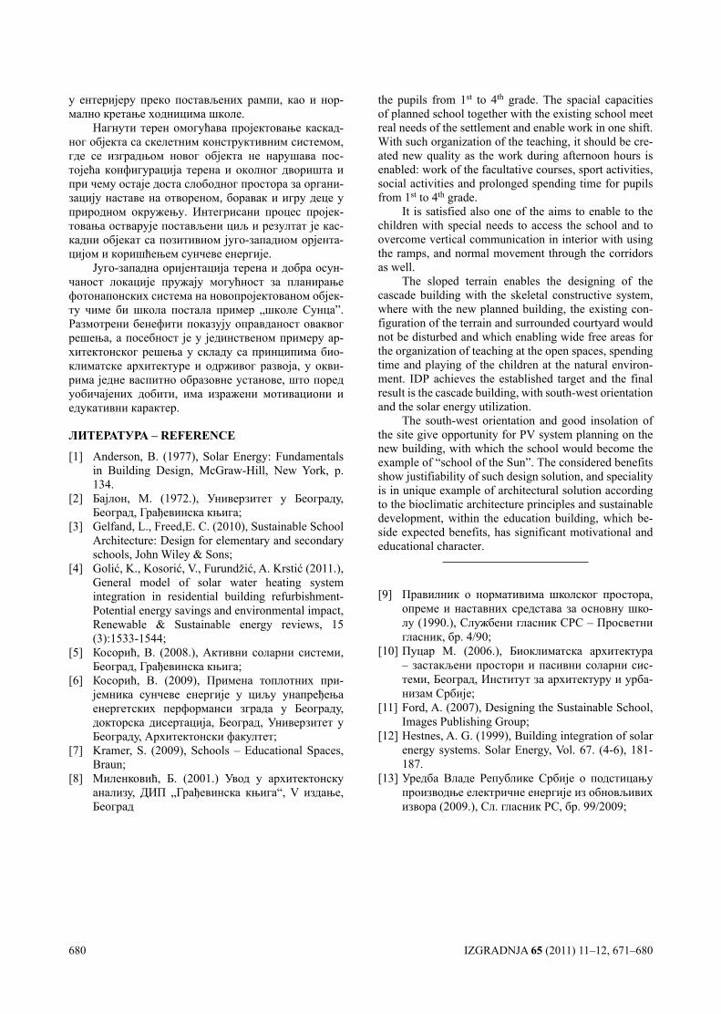
680 IZGRADNJA 65 (2011) 11–12, 671–680
у ентеријеру преко постављених рампи, као и нор-мално кретање ходницима школе.
Нагнути терен омогућава пројектовање каскад-ног објекта са скелетним конструктивним системом, где се изградњом новог објекта не нарушава пос-тојећа конфигурација терена и околног дворишта и при чему остаје доста слободног простора за органи-зацију наставе на отвореном, боравак и игру деце у природном окружењу. Интегрисани процес пројек-товања остварује постављени циљ и резултат је кас-кадни објекат са позитивном југо-западном орјента-цијом и коришћењем сунчеве енергије.
Југо-западна оријентација терена и добра осун-чаност локације пружају могућност за планирање фотонапонских система на новопројектованом објек-ту чиме би школа постала пример „школе Сунца”. Размотрени бенефити показују оправданост оваквог решења, а посебност је у јединственом примеру ар-хитектонског решења у складу са принципима био-климатске архитектуре и одрживог развоја, у окви-рима једне васпитно образовне установе, што поред уобичајених добити, има изражени мотивациони и едукативни карактер.
ЛИТЕРАТУРА – REfERENcE
[1] Аnderson, B. (1977), Solar Energy: Fundamentals in Building Design, McGraw-Hill, New York, p. 134.
[2] Бајлон, М. (1972.), Универзитет у Београду, Београд, Грађевинска књига;
[3] Gelfand, L., Freed,E. C. (2010), Sustainable School Architecture: Design for elementary and secondary schools, John Wiley & Sons;
[4] Golić, K., Kosorić, V., Furundžić, A. Krstić (2011.), General model of solar water heating system integration in residential building refurbishment-Potential energy savings and environmental impact, Renewable & Sustainable energy reviews, 15 (3):1533-1544;
[5] Косорић, В. (2008.), Активни соларни системи, Београд, Грађевинска књига;
[6] Косорић, В. (2009), Примена топлотних при-јемника сунчеве енергије у циљу унапређења енергетских перформанси зграда у Београду, докторска дисертација, Београд, Универзитет у Београду, Архитектонски факултет;
[7] Kramer, S. (2009), Schools – Educational Spaces, Braun;
[8] Миленковић, Б. (2001.) Увод у архитектонску анализу, ДИП „Грађевинска књига“, V издање, Београд
the pupils from 1st to 4th grade. The spacial capacities of planned school together with the existing school meet real needs of the settlement and enable work in one shift. With such organization of the teaching, it should be cre-ated new quality as the work during afternoon hours is enabled: work of the facultative courses, sport activities, social activities and prolonged spending time for pupils from 1st to 4th grade.
It is satisfied also one of the aims to enable to the children with special needs to access the school and to overcome vertical communication in interior with using the ramps, and normal movement through the corridors as well.
The sloped terrain enables the designing of the cascade building with the skeletal constructive system, where with the new planned building, the existing con-figuration of the terrain and surrounded courtyard would not be disturbed and which enabling wide free areas for the organization of teaching at the open spaces, spending time and playing of the children at the natural environ-ment. IDP achieves the established target and the final result is the cascade building, with south-west orientation and the solar energy utilization.
The south-west orientation and good insolation of the site give opportunity for PV system planning on the new building, with which the school would become the example of “school of the Sun”. The considered benefits show justifiability of such design solution, and speciality is in unique example of architectural solution according to the bioclimatic architecture principles and sustainable development, within the education building, which be-side expected benefits, has significant motivational and educational character.
[9] Правилник о нормативима школског простора, опреме и наставних средстава за основну шко-лу (1990.), Службени гласник СРС – Просветни гласник, бр. 4/90;
[10] Пуцар M. (2006.), Биоклиматска архитектура – застакљени простори и пасивни соларни сис-теми, Београд, Институт за архитектуру и урба-низам Србије;
[11] Ford, A. (2007), Designing the Sustainable School, Images Publishing Group;
[12] Hestnes, A. G. (1999), Building integration of solar energy systems. Solar Energy, Vol. 67. (4-6), 181-187.
[13] Уредба Владе Републике Србије о подстицању производње електричне енергије из обновљивих извора (2009.), Сл. гласник РС, бр. 99/2009;
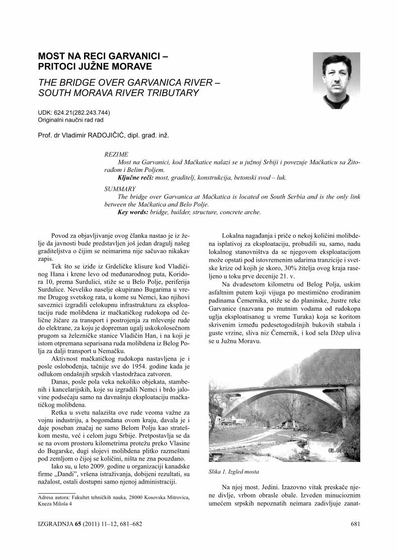
IZGRADNJA 65 (2011) 11–12, 681–682 681
Lokalna nagađanja i priče o nekoj količini molibde-na isplativoj za eksploataciju, probudili su, samo, nadu lokalnog stanovništva da se njegovom eksploatacijom može opstati pod istovremenim udarima tranzicije i svet-ske krize od kojih je skoro, 30% žitelja ovog kraja rase-ljeno u toku prve decenije 21. v.
Na dvadesetom kilometru od Belog Polja, uskim asfaltnim putem koji vijuga po mestimično erodiranim padinama Čemernika, stiže se do planinske, žustre reke Garvanice (nazvana po mutnim vodama od rudokopa uglja eksploatisanog u vreme Turaka) koja se koritom skrivenim između pedesetogodišnjih bukovih stabala i guste vrzine, sliva niz Čemernik, i kod sela Džep uliva se u Južnu Moravu.
Slika 1. Izgled mosta
Na njoj most. Jedini. Izazovno vitak preskače nje-ne divlje, vrbom obrasle obale. Izveden minucioznim umećem srpskih nepoznatih neimara zadivljuje zanat-
Povod za objavljivanje ovog članka nastao je iz že-lje da javnosti bude predstavljen još jedan dragulj našeg graditeljstva o čijim se neimarima nije sačuvao nikakav zapis.
Tek što se iziđe iz Grdeličke klisure kod Vladiči-nog Hana i krene levo od međunarodnog puta, Korido-ra 10, prema Surdulici, stiže se u Belo Polje, periferija Surdulice. Neveliko naselje okupirano Bugarima u vre-me Drugog svetskog rata, u kome su Nemci, kao njihovi saveznici izgradili celokupnu infrastrukturu za eksploa-taciju rude molibdena iz mačkatičkog rudokopa od če-lične žičare za transport i postrojenja za mlevenje rude do elektrane, za koju je dopreman ugalj uskokolosečnom prugom sa železničke stanice Vladičin Han, i na koji je istom otpremana separisana ruda molibdena iz Belog Po-lja za dalji transport u Nemačku.
Aktivnost mačkatičkog rudokopa nastavljena je i posle oslobođenja, tačnije sve do 1954. godine kada je odlukom ondašnjih srpskih vlastodržaca zatvoren.
Danas, posle pola veka nekoliko objekata, stambe-nih i kancelarijskih, koje su izgradili Nemci i brdo jalo-vine podsećaju samo na davnašnju eksploataciju mačka-tičkog molibdena.
Retka u svetu nalazišta ove rude veoma važne za vojnu industriju, a bogomdana ovom kraju, davala je i daje poseban značaj ne samo Belom Polju kao strateš-kom mestu, već i celom jugu Srbije. Pretpostavlja se da se na ovom prostoru kilometrima protežu preko Vlasine do Bugarske, dugi slojevi molibdena plitko razmeštani pod zemljom o čijoj se količini, ništa ne zna pouzdano.
Iako su, u leto 2009. godine u organizaciji kanadske firme „Dandi”, vršena istraživanja, dobijeni rezultati, su nažalost, ostali dostupni samo njenoj administraciji.
MOST NA RECI GARvANICI – PRITOCI JUŽNE MORAVETHE BRIDGE OVER GARVANICA RIVER – SOUTH MORAVA RIVER TRIBUTARY
UDK: 624.21(282.243.744) Originalni naučni rad rad
Prof. dr Vladimir RADOJIČIĆ, dipl. građ. inž.
REZIME Most na Garvanici, kod Mačkatice nalazi se u južnoj Srbiji i povezuje Mačkaticu sa Žito-
rađom i Belim Poljem.Ključne reči: most, graditelj, konstrukcija, betonski svod – luk.
SUMMARYThe bridge over Garvanica at Mačkatica is located on South Serbia and is the only link
between the Mačkatica and Belo Polje.Key words: bridge, builder, structure, concrete arche.
Adresa autora: Fakultet tehničkih nauka, 28000 Kosovska Mitrovica, Kneza Miloša 4
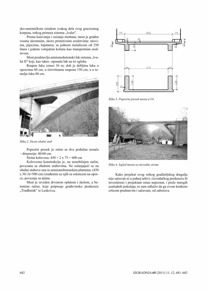
682 IZGRADNJA 65 (2011) 11–12, 681–682
sko-umetničkom izradom svakog dela svog gracioznog korpusa, retkog primera sistema „lvalet”.
Prema kazivanju i sećanju meštana, most je građen veoma skromnim, skoro primitivnim sredstvima: ašovi-ma, pijucima, lopatama, sa jednom mešalicom od 250 litara i jednim volujskim kolima kao transportnim sred-stvom.
Most predstavlja armiranobetonski luk sistema „lva-let II” koji, kao takav, oponaša luk na tri zgloba.
Raspon luka iznosi 36 m; dok je debljina luka u oporcima 60 cm, u četvrtinama raspona 150 cm, a u te-melju luka 80 cm.
Slika 2. Desni obalni stub
Poprečni presek je rešen sa dva podužna nosača – dimenzija: 40/60 cm.
Širina kolovoza: 450 + 2 x 75 = 600 cmKolovozna konstrukcija je, na neuobičajen način,
povezana sa obalnim stubovima. Ne oslanjajući se na obalne stubove ona se armiranobetonskim platnima: (450 x 30 i h=500 cm) izrađenim uz njih sa osloncem na opor-ce, povezuje sa njima.
Most je izveden drvenom oplatom i skelom, a be-toniran ručno, koje potpisuje građevinsko preduzeće „Trudbenik” iz Leskovca.
Kako projekat ovog retkog graditeljskog dragulja nije sačuvan ni u jednoj arhivi, (izvođačkog preduzeća ili investitora) i projektant ostao nepoznat, i posle mnogih uzaludnih pokušaja, to sam odlučio da ga ovom kratkom crticom predstavim i sačuvam, od zaborava.
Slika 3. Poprečni presek mosta u l/4
Slika 4. Izgled mosta sa nizvodne strane
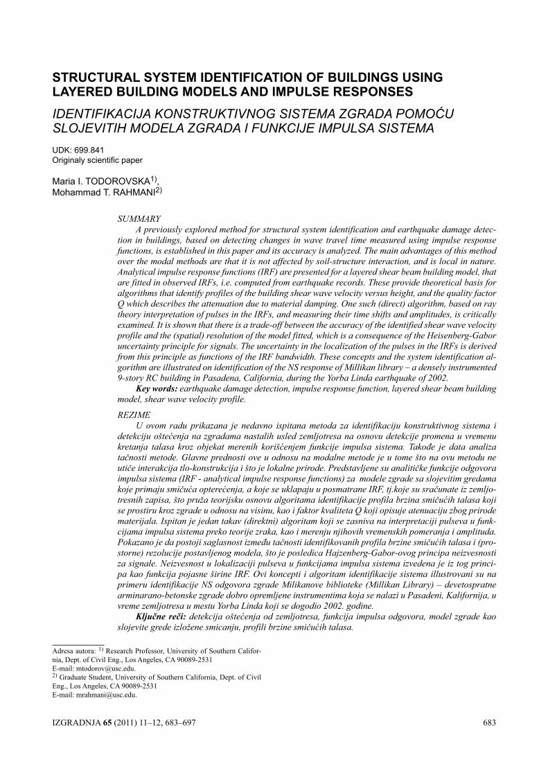
IZGRADNJA 65 (2011) 11–12, 683–697 683
STRUCTURAL SySTEM IDENTIfICATION Of BUILDINGS USING LAyERED BUILDING MODELS AND IMPULSE RESPONSESIDENTIFIKACIJA KONSTRUKTIVNOG SISTEMA ZGRADA POMOĆU SLOJEVITIH MODELA ZGRADA I FUNkCIJE IMPULSA SISTEMAUDK: 699.841 Originaly scientific paper
Maria I. TODOROVSKA1), Mohammad T. RAHMANI2)
SUMMARYA previously explored method for structural system identification and earthquake damage detec-
tion in buildings, based on detecting changes in wave travel time measured using impulse response functions, is established in this paper and its accuracy is analyzed. The main advantages of this method over the modal methods are that it is not affected by soil-structure interaction, and is local in nature. Analytical impulse response functions (IRF) are presented for a layered shear beam building model, that are fitted in observed IRFs, i.e. computed from earthquake records. These provide theoretical basis for algorithms that identify profiles of the building shear wave velocity versus height, and the quality factor Q which describes the attenuation due to material damping. One such (direct) algorithm, based on ray theory interpretation of pulses in the IRFs, and measuring their time shifts and amplitudes, is critically examined. It is shown that there is a trade-off between the accuracy of the identified shear wave velocity profile and the (spatial) resolution of the model fitted, which is a consequence of the Heisenberg-Gabor uncertainty principle for signals. The uncertainty in the localization of the pulses in the IRFs is derived from this principle as functions of the IRF bandwidth. These concepts and the system identification al-gorithm are illustrated on identification of the NS response of Millikan library – a densely instrumented 9-story RC building in Pasadena, California, during the Yorba Linda earthquake of 2002.
Key words: earthquake damage detection, impulse response function, layered shear beam building model, shear wave velocity profile.
REZIMEU ovom radu prikazana je nedavno ispitana metoda za identifikaciju konstruktivnog sistema i
detekciju oštećenja na zgradama nastalih usled zemljotresa na osnovu detekcije promena u vremenu kretanja talasa kroz objekat merenih korišćenjem funkcije impulsa sistema. Takođe je data analiza tačnosti metode. Glavne prednosti ove u odnosu na modalne metode je u tome što na ovu metodu ne utiče interakcija tlo-konstrukcija i što je lokalne prirode. Predstavljene su analitičke funkcije odgovora impulsa sistema (IRF - analytical impulse response functions) za modele zgrade sa slojevitim gredama koje primaju smičuća opterećenja, a koje se uklapaju u posmatrane IRF, tj.koje su sračunate iz zemljo-tresnih zapisa, što pruža teorijsku osnovu algoritama identifikacije profila brzina smičućih talasa koji se prostiru kroz zgrade u odnosu na visinu, kao i faktor kvaliteta Q koji opisuje atenuaciju zbog prirode materijala. Ispitan je jedan takav (direktni) algoritam koji se zasniva na interpretaciji pulseva u funk-cijama impulsa sistema preko teorije zraka, kao i merenju njihovih vremenskih pomeranja i amplituda. Pokazano je da postoji saglasnost između tačnosti identifikovanih profila brzine smičućih talasa i (pro-storne) rezolucije postavljenog modela, što je posledica Hajzenberg-Gabor-ovog principa neizvesnosti za signale. Neizvesnost u lokalizaciji pulseva u funkcijama impulsa sistema izvedena je iz tog princi-pa kao funkcija pojasne širine IRF. Ovi koncepti i algoritam identifikacije sistema illustrovani su na primeru identifikacije NS odgovora zgrade Milikanove biblioteke (Millikan Library) – devetospratne arminarano-betonske zgrade dobro opremljene instrumentima koja se nalazi u Pasadeni, Kalifornija, u vreme zemljotresa u mestu Yorba Linda koji se dogodio 2002. godine.
Ključne reči: detekcija oštećenja od zemljotresa, funkcija impulsa odgovora, model zgrade kao slojevite grede izložene smicanju, profili brzine smičućih talasa.
Adresa autora: 1) Research Professor, University of Southern Califor-nia, Dept. of Civil Eng., Los Angeles, CA 90089-2531E-mail: [email protected]) Graduate Student, University of Southern California, Dept. of Civil Eng., Los Angeles, CA 90089-2531E-mail: [email protected].
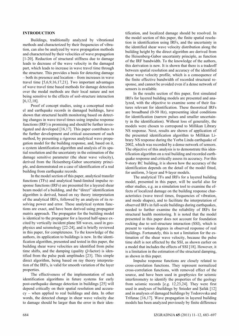
684 IZGRADNJA 65 (2011) 11–12, 683–697
INTRODUcTION
Buildings, traditionally analyzed by vibrational methods and characterized by their frequencies of vibra-tion, can also be analyzed by wave propagation methods and characterized by their velocities of wave propagation [1-20]. Reduction of structural stiffness due to damage leads to decrease of the wave velocity in the damaged part, which leads to increase in wave travel time through the structure. This provides a basis for detecting damage – both its presence and location – from increases in wave travel time [5,6,9,16,17,21]. Two important advantages of wave travel time based methods for damage detection over the modal methods are their local nature and not being sensitive to the effects of soil-structure interaction [6,12,18].
Proof of concept studies, using a conceptual mod-el and earthquake records in damaged buildings, have shown that structural health monitoring based on detect-ing changes in wave travel times using impulse response functions (IRF) is promising and should be further inves-tigated and developed [16,17]. This paper contributes to the further development and critical assessment of such method, by presenting a rigorous analytical wave propa-gation model for the building response, and, based on it, a system identification algorithm and analysis of its spa-tial resolution and the uncertainty in the estimation of the damage sensitive parameter (the shear wave velocity), derived from the Heisenberg-Gabor uncertainty princi-ple, and demonstrated on a case of identification of a real building from earthquake records.
In the model section of this paper, analytical transfer functions (TFs) and analytical band-limited impulse re-sponse functions (IRFs) are presented for a layered shear beam model of a building, and the “direct” identification algorithm is derived, based on ray theory interpretation of the analytical IRFs, followed by an analysis of its re-solving power and error. These analytical system func-tions are exact, and have been derived using propagator matrix approach. The propagator for the building model is identical to the propagator for a layered half-space ex-cited by vertically incident plane SH waves, used in geo-physics and seismology [22-24], and is briefly reviewed in this paper, for completeness. To the knowledge of the authors, its application to buildings is new. In the identi-fication algorithm, presented and tested in this paper, the building shear wave velocities are identified from pulse time shifts, and the damping (quality Q-factor) is iden-tified from the pulse peak amplitudes [23]. This simple direct algorithm, being based on ray theory interpreta-tion of the IRFs, is valid for smooth variation of the layer properties.
The effectiveness of the implementation of such identification algorithms in future systems for early post-earthquake damage detection in buildings [25] will depend critically on their spatial resolution and accura-cy – when applied to real buildings and data. In other words, the detected change in shear wave velocity due to damage should be larger than the error in their iden-
tification, and localized damage should be resolved. In the model section of this paper, the finite spatial resolu-tion in identification using IRFs, and the uncertainty in the identified shear wave velocity distribution along the building height by the direct algorithm are derived from the Heisenberg-Gabor uncertainty principle, as function of the IRF bandwidth. To the knowledge of the authors, this derivation is new. It is shown that there is a tradeoff between spatial resolution and accuracy of the identified shear wave velocity profile, which is a consequence of the finite effective bandwidth of recorded structural re-sponse, and cannot be avoided even if a dense network of sensors is available.
In the results section of this paper, first simulated IRFs for layered building models are presented and ana-lyzed, with the objective to examine some of their fea-tures relevant for identification. These theoretical IRFs are broadband (0-50 Hz), representing ideal conditions for identification (narrow pulses and smaller uncertain-ty in the identification). Without loss of generality, the models were chosen to correspond to Millikan Library NS response. Next, results are shown of application of the presented identification algorithm to Millikan Li-brary NS response during the Yorba Linda earthquake of 2002, which was recorded by a dense network of sensors. The objective of this analysis is to demonstrate this iden-tification algorithm on a real building and recorded earth-quake response and critically assess its accuracy. For this 9-story RC building, it is shown how the accuracy of the identification depends on the detail of the model fitted, for uniform, 3-layer and 9-layer models.
The analytical TFs and IRFs for a layered building model, presented in this paper, will be useful also for other studies, e.g. as a simulation tool to examine the ef-fects of localized damage on the building response char-acteristics (wave travel times, frequencies of vibration, and mode shapes), and to facilitate the interpretation of observed IRFs in full-scale buildings during earthquakes, needed to further examine the reliability of IRFs for structural health monitoring. It is noted that the model presented in this paper does not account for foundation rocking due to soil-structure interaction (SSI), which is present to various degrees in observed response of real buildings. Fortunately, this is not a limitation for the es-timation of the shear wave velocity, because the pulse time shift is not affected by the SSI, as shown earlier on a model that includes the effects of SSI [18]. However, it is a limitation in the estimation of the structural damping, as shown in this paper.
Impulse response functions are closely related to cross-correlation functions. They represent normalized cross-correlation functions, with removed effect of the source, and have been used in geophysics for seismic interferometry to identify the properties of the geology from seismic records [e.g. 12,23,24]. They were first used in analyses of buildings by Snieder and Şafak [12] and in analyses of damaged buildings by Todorovska and Trifunac [16,17]. Wave propagation in layered building models has been analyzed previously by finite difference
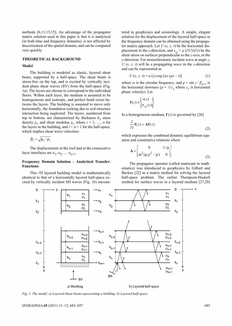
IZGRADNJA 65 (2011) 11–12, 683–697 685
methods [6,11,13,15]. An advantage of the propagator matrix solution used in this paper is that it is analytical (in both time and frequency domains), is not affected by discretization of the spatial domain, and can be computed very quickly.
ThEORETIcAl BAcKgROUND
Model
The building is modeled as elastic, layered shear beam, supported by a half-space. The shear beam is stress-free on the top, and is excited by vertically inci-dent plane shear waves (SV) from the half-space (Fig. 1a). The layers are chosen to correspond to the individual floors. Within each layer, the medium is assumed to be homogeneous and isotropic, and perfect bond exists be-tween the layers. The building is assumed to move only horizontally, the foundation rocking due to soil-structure interaction being neglected. The layers, numbered from top to bottom, are characterized by thickness hi, mass density ρi, and shear modulus μi, where i = 1, …, n for the layers in the building, and i = n + 1 for the half-space, which implies shear wave velocities:
/i i iβ µ ρ=
The displacements at the roof and at the consecutive layer interfaces are u1, u2, … un+1.
frequency Domain Solution – Analytical Transfer-functions
This 1D layered building model is mathematically identical to that of a horizontally layered half-space ex-cited by vertically incident SH waves (Fig. 1b) encoun-
tered in geophysics and seismology. A simple, elegant solution for the displacement of the layered half-space in the frequency domain can be obtained using the propaga-tor matrix approach. Let U (x, z; t) be the horizontal dis-placement in the y-direction, and τzy = μ (∂U)/(∂z) be the shear stress on surfaces perpendicular to the z-axis, in the y-direction. For monochromatic incident wave at angle γ, U (x, z; t) will be a propagating wave in the x-direction and can be represented as
U (x, z; t) = u (z) exp [iω (px – t)] (1)
where ω is the circular frequency, and p = sin γ / βn+1 is the horizontal slowness (p = 1/cx where cx is horizontal phase velocity). Let
( )( )
( )zy
v zz
zτ ≡
f
In a homogeneous medium, f (z) is governed by [26]
( ) ( )z zz∂
=∂
f Af (2)
which expresses the combined dynamic equilibrium equ-ation and constitutive relations where
2 2
0 1/
( ) 0p
µ
ω µ ρ
=
− A
(3)
The propagator operator (called matricant in math-ematics) was introduced to geophysics by Gilbert and Backus [22] as a matrix method for solving the layered half-space problem. The earlier Thompson-Haskell method for surface waves in a layered medium [27,28]
Fig. 1. The model. a) Layered shear-beam representing a building. b) Layered half-space.
686 IZGRADNJA 65 (2011) 11–12, 683–697
is a special cases of the propagator matrix method. The following summarizes briefly how the solution for f (z) is obtained using the propagator matrix. If matrix A in eqn (2) is a continuous function of z, which is the case within each layer, then the uniqueness theorem implies that the solution at any point z in the layer can be obtained from the solution at another point z0 in the same layer as
f (z) = P (z, z0) f (z0) (4)
where P (z, z0) is the propagator for that layer from z0. The propagator P (z, z0) can be obtained from the funda-mental matrix of the system of eqns (2), f (z), as
P (z, z0) = f (z) f (z0)–1 (5)
which gives
11 0 0
12 0 0
21 0 0
22 0 0
P ( , ) cos ( )
P ( , ) sin ( )
P ( , ) ( )sin ( )P ( , ) cos ( )
z z z ziz z z z
iz z i i z zz z z z
ωη
ωηωηµ
ωηµ ωηωη
= −
= −
= −
= − (6)where
22
1 pηβ
= −
is the vertical slowness (= 1/cz where cz is vertical phase velocity).
The continuity conditions imply that f (z) must be continuous at the layer interfaces, which enables one to compute f (z) from any location within the layered me-dium where it is known. Starting from z = 0 with f (0) = {1 0}T, f (z) can be computed recursively at the layer interfaces z = z1, z2, …, and from there propagated inside the layers. Then, the propagator from z = 0 to any point z in the layered medium, P (z, 0), can be derived such that
f (z) = P (z, 0) f (0), zi–1 ≤ z ≤ zi, i = 1,…,n (7)
P (z, 0) = P (z, zi–1) P (zi–1, zi–2) ··· ··· P (z2, z1) P (z1, 0) (8)
where P (zj, zj–1) is the propagator for the j–th layer, gi-ven by eqn (6). For the 1D building model (Fig. 1a), in eqn (6), p = 0, and η = 1/β.
The first entry of f (z) being u (z), eqn (7) implies that P11 (z, 0) gives the transfer-function (TF) between the displacement at level z and the displacement at the top, the inverse Fourier transform of which would be the impulse response functions (IRF) for virtual source at the top. Using eqn (7), the system functions (TFs and IRFs) can be computed with respect to any reference level. Let h (z, zref; t) be the IRF at some level z with respect to level zref, and let ref
ˆ( , ; )h z z ω be its Fourier transform. Then
ref 11 11 refˆ( , ; ) ( ,0) / ( ,0)h z z z zω = P P (9)
{ }1ref ref
ˆ( , ; ) ( , ; )h z z t FT h z z ω−= (10)
where FT–1 indicates inverse Fourier transform following the convention
1ˆ ˆ( ) ( ) ( ) ( )2
i t i tf f t e dt f t f e dω ωω ω ωπ
∞ ∞−
−∞ −∞= ⇔ =∫ ∫
(11)
At the reference level:
ref refˆ( , ; ) 1h z z ω =
and the impulse response function h (z, , zref, zref; t) = δ (t) = Dirac delta-function, which represents a virtual source. Away from the source, h (z, zref; t) represents the respon-se of the building to the virtual source at z = zref. When the virtual source does not coincide with the physical so-urce, acausal pulses will appear in the impulse response functions [12].
To account for amplitude attenuation due to mate-rial friction, quality factor Q is introduced, which de-scribes the amplitude reduction of a propagating wave or a vibrating volume over one cycle. Let A0 be the initial amplitude, and A be the amplitude after distance travelled z or time of vibration t. Then A (t; ω) = A0 exp [–ωt/(2Q)] and A (z; ω) = A0 exp [–ωz/(2Qβ)] [26]. High Q implies small attenuation, and for constant Q and fixed distance, the higher frequency waves are attenuated more. It is in-corporated in the model by replacing the real valued ver-tical slowness η = 1/β by complex slowness ηcmplx
12
cmplx iQ
η η η= + (12)
Q is related to the damping ratio ζ (ratio of damping and critical damping of viscously damped oscillators) by ζ = 1/(2Q). Then, ζ = 1% is equivalent to Q = 50, which is value typical for sediments. It is usually assumed that Q and ζ are frequency independent, but in general both are strong functions of frequency [29]. As a consequence of Q, the pulse propagation will be dispersed, however, for lightly damped structures, this effect is small.
Ray Theory Interpretation of IRfs
The ray theory [26] interpretation of the IRFs leads to a simple direct algorithm for identification of the lay-ers, presented and tested in this paper. However, it is ap-proximate theory that involves underlying assumptions, which need to be satisfied to obtain give accurate results. In this section, these assumptions and the derivation of the travel time formula are briefly reviewed. Ray the-ory is based on the assumption that body waves travel through an inhomogeneous medium as a wave front, with the local propagation speeds, obeying the laws of geo-metric optics, i.e. along ray paths determined by Snell’s law [26]. For the 1D layered building model (Fig. 1), let T (z; z0) be the travel time from z0 to z. An equation for T is obtained from the wave equation by trying approxi-mate solution
IZGRADNJA 65 (2011) 11–12, 683–697 687
u (z, t) = U (t – T (z)) f (z) (13)
where U is the source function, and f (z) is some function of z. Assuming that near the wave front U fluc-tuates much more rapidly than the material properties and f, and that its derivatives fluctuate even more rapidly, and neglecting the corresponding terms gives
1( )( )
T zzβ
′ = (14)
Then the travel time between points A and B is the line integral
1( )AB
ABT ds
sβ= ∫
(15)
which becomes a sum for our model. This implies travel time over the height of the building is a sum of the tra-vel time through the individual layers, which holds if the material properties along the path vary smoothly. If there are abrupt variations, then wave scattering and diffrac-tion become significant, and the full wave propagation theory needs to be applied for accurate results.
Time Domain Solution – Analytical Impulse Response functions
In practice, the impulse response functions (IRF) are computed from band-limited transfer-functions over |ω| ≤ ωmax
max
max
ref ref1 ˆ( , ; ) ( , ; )
2i th z z t h z z e d
ωω
ωω ω
π−
−= ∫
(16)
An important benefit of eqn (16) is the convergence of the integral for Q > 0, which is not the case when ωmax → ∞ [23]. Then, the source pulse is a box function in the frequency domain, and sinc function (sin ωmax t)/(πt) in the time domain. The integration in eqn. (16) can be car-ried out both numerically, using Fast Fourier Transform, and analytically. The latter are very useful for devising identification algorithms, as shown in the next two sec-tions.
When zref = 0 (the top), the kernel in eqn (16) is the propagator P11 (z, 0) in eqn. (8), and analytical in-tegration of eqn (16) gives the following expression for band-limited IRF at some level m ≤ n normalized to unit amplitude at the source [23]
1 ( )2( ,0; )
( )1
( ) ( ) ( ) ( )
m maih z tm mbim m m mSC t SA ti i i iτ τ
−
= ⋅=
⋅ − + +
∑
(17)
where SCi(m)(t) and SAi
(m)(t) are inverse Fourier tran-sforms of attenuated box functions for causal and acausal waves given by
( ) ( )
max( )exp1( ) ( )
2( ) 2
( )( ) cos sin
2
max
max a(
x2
m)
imSC titi
it t titi
m
m
mm
m
α ω
ωα
αα ω ω
α
− = +
− − + − +
(18)
( ) ( )
max( )exp1( ) ( )
2( ) 2
( )( ) cos sin
2( )
max
max max2
imSA titi
it t tit
m
m
mm
mi
α ω
ωα
αα ω ω
α
= +
+ −
+ (19)
In eqn. (17), τi(m) are time shifts such that
(0) 011) ) 1)
2 1 2( ) ( ( (;h hm m m m
m mii m miiη
τ
τ τ τ ητ− −= + = −−
=
(20)
and the coefficients ai(m) and b(m) are functions of the re-
flection and transmission coefficients R and T such that
(0) 11( ) ( 1) ( ) ( 1) , - odd2 1 2( ) ( 1) ( ) ( 1) , - even2 1
,
2,
m m m mm
m m
a
a a a a R ii ii i
a a R a am mm ii ii i
=
− −= =−− −= =− (21)
( ) 2 ( )2
mb T jj
m=
=∏
(22)
where Rm is the reflection coefficient of waves in m-th layer reflected from the interface with the (m – 1) – th layer and Tj is the transmission coefficient for waves from the j-th layer into the (j – 1)-th layer defined as
1 11 1
m m m mm
m m m mR
η µ η µη µ η µ
− − −=+ − − (23)
2
1 1
j jT jj j j j
η µ
η µ η µ=
+ − − (24)
In eqns (18) and (19), αi(m) are amplitude attenua-
tion factors
688 IZGRADNJA 65 (2011) 11–12, 683–697
(0) 01( ) 1) ;2 1
) )( ( 12
(m hii
h mii
mm m m
m mm m
α
α α η ς
α α η ς
=
−= +−−= −
(25)
The other parameters are same as defined earlier, i.e. hm is the thickness, ηm = 1/βm is the vertical slowness, ςm = 1 / (2Qm) and μm is the shear modulus, all of these of the m-th layer.
As shown by eqn. (17), the impulse response func-tion at each interface represents an assembly of shifted in time sinc functions, which include the transmitted causal and acausal pulses, and reflections from the layer inter-faces.
The Direct Identification Algorithm
Based on ray theory, applicable when the variations of material properties is “smooth” so that the effects of scattering from the inhomogeneities are small, the ana-lytical IRFs in eqn (17) imply that the velocities βm can be obtained from the time shifts τi
(m) of the pulses, and the quality factors Qm can be obtained further from the ratios of the amplitudes of the causal and acausal pulses SCi
(m)(0) and SAi(m)(0) [23]. If there is a recording at
every layer interface, all layers can be identifies only from the transmitted pulse (i = 1), from the relationships
( ) ( 1) /1 1m m hm mτ τ β−− =
(26)
( ) ( 1)(0) (0)1 1( ) ( 1)(0) (0)1 1
ln ln
( ) ( 1)max 1 1
m mSA SAm
m m
mS S
m
C C
τ τω ς
−− =
−= −
−
(27)
where ςm = 1 / (2Qm), which implies
( ) ( 1)1 1
m mhm m τ τβ − = − (28)
( ) ( 1)(0) (0)1 1
1 1 1( ) ( 1
( ) ( 1)(0) (0)1 1
)2 max 1 1
ln lnm
m
mSA SAm mSC
m
SC
Qm ω τ τ
= ⋅ − − ⋅ − −
−
(29)
and overall Q
( ) (0)1(
1 1 ln)( )2
ma 1 ( )1x 0
nSA
SCm nQ ω τ=
(30)
where τ1(m) is the travel time from base to roof. If there
isn’t a sensor at each layer boundaries, it is still possible, in principal, to identify all the layers, using the reflected pulses. This requires that the reflected pulses have ampli-tudes larger than the ripples of the transmitted pulses, and are sufficiently shifted in time to be resolved as separate pulses, so that they can be identified.
heisenberg-gabor Uncertainty Principle and its con-sequences on the Identification
The source pulse:
maxref ref
sin( , ; )
th z z t
tωπ
=
is localized both in time and in frequency, around time 0t = and frequency max / 2ω ω= , but not perfectly.
Its spread in frequency is Δω = ωmax/2, and let the half-width of the main lobe Δω =π/ ωmax = 1/(2fmax) be a measure of its spread in time, where fmax = ωmax/(2π). (It is noted here that the spread in time cannot be derived using the second moment, because it does not exist for the sinc function.) This implies that smaller ωmax would result in a wider source pulse, which will worsen the time localization of the IRFs, and, consequently, the spatial localization of the wave front. The product of Δω and Δt for the source pulse is always constant
2t πω∆ ∆ =
(31)
Eqn. represents the Heisenberg-Gabor uncertainty principle for signals [30,31], according to which a sig-nal cannot be perfectly localized both in time and in fre-quency, and increased localization in one domain is at the expense of decrease localization in the other domain. Its equivalent in physics states that both the position and velocity of a particle cannot be determined exactly at a given moment in time. An important consequence of this principle is the finite spatial resolution of the identifi-cation of the variations of the layer properties, and the uncertainty in the identified properties at a particular location in the building. As demonstrated in the results section, the limited resolving power implies that there is some minimum thickness of the top layer that can be re-solved by the IRFs, even if there exists a recording within that layer.
The related uncertainties Δz and Δβ can be derived from the Heisenberg-Gabor uncertainty principle and in-terpreted as follows. The disturbance at the virtual source will propagate through the medium as a pulse in space with half-width Δz = βΔt = πβ/ωmax. Further, Δz can be expressed as Δz = Δβτ, where Δβ is uncertainty in β and τ is travel time, which gives Δβ/β = π/(ωmax τ). This means that the “point” estimate of velocity β(z), measured from the time shift of the of a pulse in the IRF, is a weighted average over the interval [z – Δz, z + Δz], and that the identified value of β is an estimate, the error of which has distribution with spread Δβ. Recalling that π/ωmax = Δt,
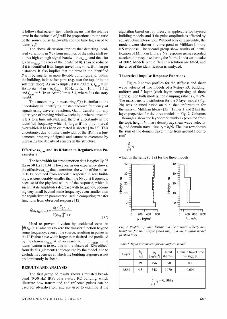
IZGRADNJA 65 (2011) 11–12, 683–697 689
it follows that Δβ/β = Δt/τ, which means that the relative error in the estimate of β will be proportional to the ratio of the source pulse half-width and the time lag τ used to identify β.
The above discussion implies that detecting local-ized variations in β(z) from readings of the pulse shift re-quires high enough signal bandwidth ωmax, and that, for given ωmax, the error of the identified β(z) can be reduced if it is identified from larger travel time τ, i.e. from larger distances. It also implies that the error in the identified β will be smaller in more flexible buildings, and, within the building, in its softer parts (e.g. near the top, or in the soft first floor). As an example, if β ≈ 200 m/s, fmax = 25 Hz ⇒ Δz ≈ 4 m ≈ h, fmax = 10 Hz ⇒ Δz ≈ 10 m ≈ 2.5 h, and fmax = 5 Hz ⇒ Δz = 20 m ≈ 5 h, where h is the story height.
This uncertainty in measuring β(z) is similar to the uncertainty in identifying “instantaneous” frequency of signals using wavelet transform, Gabor transform or any other type of moving window technique where “instant” refers to a time interval, and there is uncertainty in the identified frequency which is larger if the time interval over which it has been estimated is shorter [30-32]. This uncertainty, due to finite bandwidth of the IRF, is a fun-damental property of signals and cannot be overcome by increasing the density of sensors in the structure.
Effective ωmax and Its Relation to Regularization Pa-rameter ε
The bandwidth for strong motion data is typically 25 Hz or 50 Hz [33,34]. However, as our experience shows, the effective ωmaxthat determines the width of the pulses in IRFs obtained from recorded response in real build-ings, is considerably smaller than the Nyquist frequency, because of the physical nature of the response, which is such that its amplitudes decrease with frequency, becom-ing very small beyond some frequency, even smaller than the regularization parameter ε used in computing transfer functions from observed response [12]
refref 2
ref
ˆ ˆ( ) ( )ˆ( , ; )ˆ( )
u z u zh z z
u zω
ε=
+ (32)
Used to prevent division by accidental zeros in refˆ( ) ,u z ε also sets to zero the transfer function beyond
some frequency, even at the source, resulting in pulses in the IRFs that have width larger than desired and predicted by the chosen ωmax. Another reason to limit ωmax in the identification is to exclude in the observed IRFs effects from details (elements) not captured by the model, and to exclude frequencies at which the building response is not predominantly in shear.
RESUlTS AND ANAlySIS
The first group of results shows simulated broad-band (0-50 Hz) IRFs of a 9-story RC building, which illustrate how transmitted and reflected pulses can be used for identification, and are used to examine if the
algorithm based on ray theory is applicable for layered building models, and if the pulse amplitude is affected by soil-structure interaction. Without loss of generality, the models were chosen to correspond to Millikan Library NS response. The second group show results of identi-fication of Millikan Library NS response using recorded acceleration response during the Yorba Linda earthquake of 2002. Models with different resolution are fitted, and the error of the identification is analyzed.
Theoretical Impulse Response functions
Figure 2 shows profiles for the stiffness and shear wave velocity of two models of a 9-story RC building: uniform and 3-layer (each layer comprising of three stories). For both models, the damping ratio is ζ = 2%. The mass density distribution for the 3-layer model (Fig. 2b) was obtained based on published information for the mass of Millikan library [35]. Tables 1 and 2 list the layer properties for the three models in Fig. 2. Columns 1 through 4 show the layer order number i (counted from the top), height hi, mass density mi, shear wave velocity βi, and domain travel time τi = hi/βi. The last row shows the sum of the domain travel times from ground floor to roof:
1
ni
iτ
=∑
which is the same (0.1 s) for the three models.
Fig. 2. Profiles of mass density and shear wave velocity dis-tributions for the 3-layer (solid line) and the uniform model (dashed line).
Table 1. Input parameters for the uniform model
Layer hi[m]
ρi [kg/m3]
Inputβi [m/s]
Domain travel time τi = hi/βi [s]
1 39 496 390 0.1
BSM 4.3 548 1070 0.004
1
10.104 si
iτ
==∑
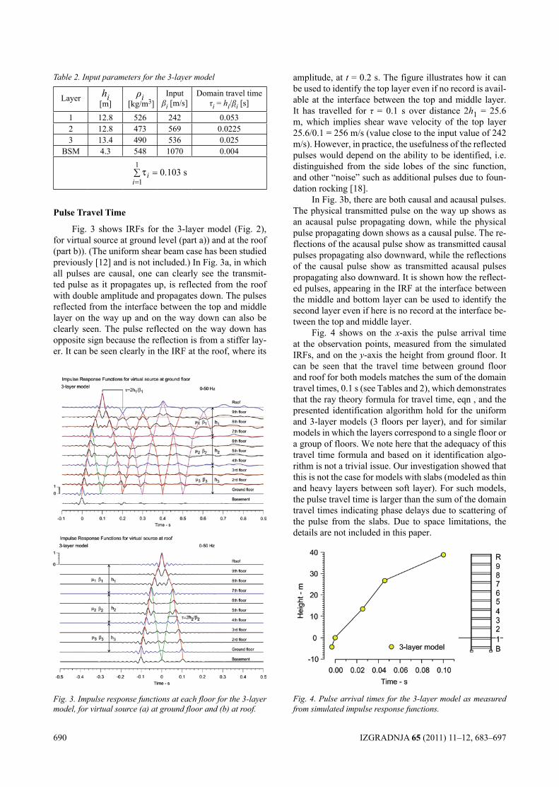
690 IZGRADNJA 65 (2011) 11–12, 683–697
Table 2. Input parameters for the 3-layer model
Layer hi[m]
ρi [kg/m3]
Inputβi [m/s]
Domain travel time τi = hi/βi [s]
1 12.8 526 242 0.0532 12.8 473 569 0.02253 13.4 490 536 0.025
BSM 4.3 548 1070 0.0041
10.103 si
iτ
==∑
Pulse Travel Time
Fig. 3 shows IRFs for the 3-layer model (Fig. 2), for virtual source at ground level (part a)) and at the roof (part b)). (The uniform shear beam case has been studied previously [12] and is not included.) In Fig. 3a, in which all pulses are causal, one can clearly see the transmit-ted pulse as it propagates up, is reflected from the roof with double amplitude and propagates down. The pulses reflected from the interface between the top and middle layer on the way up and on the way down can also be clearly seen. The pulse reflected on the way down has opposite sign because the reflection is from a stiffer lay-er. It can be seen clearly in the IRF at the roof, where its
amplitude, at t = 0.2 s. The figure illustrates how it can be used to identify the top layer even if no record is avail-able at the interface between the top and middle layer. It has travelled for τ = 0.1 s over distance 2h1 = 25.6 m, which implies shear wave velocity of the top layer 25.6/0.1 = 256 m/s (value close to the input value of 242 m/s). However, in practice, the usefulness of the reflected pulses would depend on the ability to be identified, i.e. distinguished from the side lobes of the sinc function, and other “noise” such as additional pulses due to foun-dation rocking [18].
In Fig. 3b, there are both causal and acausal pulses. The physical transmitted pulse on the way up shows as an acausal pulse propagating down, while the physical pulse propagating down shows as a causal pulse. The re-flections of the acausal pulse show as transmitted causal pulses propagating also downward, while the reflections of the causal pulse show as transmitted acausal pulses propagating also downward. It is shown how the reflect-ed pulses, appearing in the IRF at the interface between the middle and bottom layer can be used to identify the second layer even if here is no record at the interface be-tween the top and middle layer.
Fig. 4 shows on the x-axis the pulse arrival time at the observation points, measured from the simulated IRFs, and on the y-axis the height from ground floor. It can be seen that the travel time between ground floor and roof for both models matches the sum of the domain travel times, 0.1 s (see Tables and 2), which demonstrates that the ray theory formula for travel time, eqn , and the presented identification algorithm hold for the uniform and 3-layer models (3 floors per layer), and for similar models in which the layers correspond to a single floor or a group of floors. We note here that the adequacy of this travel time formula and based on it identification algo-rithm is not a trivial issue. Our investigation showed that this is not the case for models with slabs (modeled as thin and heavy layers between soft layer). For such models, the pulse travel time is larger than the sum of the domain travel times indicating phase delays due to scattering of the pulse from the slabs. Due to space limitations, the details are not included in this paper.
Fig. 4. Pulse arrival times for the 3-layer model as measured from simulated impulse response functions.
Fig. 3. Impulse response functions at each floor for the 3-layer model, for virtual source (a) at ground floor and (b) at roof.
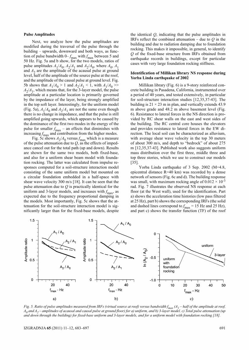
IZGRADNJA 65 (2011) 11–12, 683–697 691
Pulse Amplitudes
Next, we analyze how the pulse amplitudes are modified during the traversal of the pulse through the building – upwards, downward and both ways, as func-tion of pulse bandwidth 0– fmax with fmax between 5 and 50 Hz. Fig. 5a and b show, for the two models, ratios of pulse amplitudes A1/A0, A2/A1 and A2/A0, where A0, A1 and A2 are the amplitude of the acausal pulse at ground level, half of the amplitude of the source pulse at the roof, and the amplitude of the causal pulse at ground level. Fig. 5b shows that A1/A0 > 1 and A2/A1 < 1, with A1/A0 >> A2/A1, which means that, for the 3-layer model, the pulse amplitude at a particular location is primarily governed by the impedance of the layer, being strongly amplified in the top soft layer. Interestingly, for the uniform model (Fig. 5a), A1/A0 and A2/A1 are not the same even though there is no change in impedance, and that the pulse is still amplified going upwards, which appears to be caused by the dominance of the first two modes in the energy of the pulse for smaller fmax – an effects that diminishes with increasing fmax and contribution from the higher modes.
Fig. 5c shows A2/A0 versus fmax which is a measure of the pulse attenuation due to Q, as the effects of imped-ance cancel out for the total path (up and down). Results are shown for the same two models, both fixed-base, and also for a uniform shear beam model with founda-tion rocking. The latter was calculated from impulse re-sponses computed for a soil-structure interaction model consisting of the same uniform model but mounted on a circular foundation embedded in a half-space with shear wave velocity 300 m/s [18]. It can be seen that the pulse attenuation due to Q is practically identical for the uniform and 3-layer models, and increases with fmax, as expected due to the frequency proportional damping in the models. Most importantly, Fig. 5c shows that the at-tenuation for the soil-structure interaction model is sig-nificantly larger than for the fixed-base models, despite
the identical Q, indicating that the pulse amplitudes in IRFs reflect the combined attenuation – due to Q in the building and due to radiation damping due to foundation rocking. This makes it impossible, in general, to identify Q of the fixed-base structure from IRFs obtained from earthquake records in buildings, except for particular cases with very large foundation rocking stiffness.
Identification of Millikan library NS response during yorba linda earthquake of 2002
Millikan library (Fig. 6) is a 9-story reinforced con-crete building in Pasadena, California, instrumented over a period of 40 years, and tested extensively, in particular for soil-structure interaction studies [12,35,37-43]. The building is 21 × 23 m in plan, and vertically extends 43.9 m above grade and 48.2 m above basement level (Fig. 6). Resistance to lateral forces in the NS direction is pro-vided by RC shear walls on the east and west sides of the building. The RC central core houses the elevators and provides resistance to lateral forces in the EW di-rection. The local soil can be characterized as alluvium, with average shear wave velocity in the top 30 meters of about 300 m/s, and depth to “bedrock” of about 275 m [12,35,37-43]. Published work also suggests uniform mass distribution over the first three, middle three and top three stories, which we use to construct our models [35].
Yorba Linda earthquake of 3 Sep. 2002 (M=4.8, epicentral distance R=40 km) was recorded by a dense network of sensors (Fig. 6c and d). The building response was small, with maximum rocking angle of 0.012 × 10⁻³ rad. Fig. 7 illustrates the observed NS response at each floor (at the West wall), used for the identification. Part a) shows the acceleration time histories (low pass filtered at 25 Hz), part b) shows the corresponding IRFs (the solid and dashed lines correspond to fmax = 15 Hz and 25 Hz), and part c) shows the transfer function (TF) of the roof
Fig. 5. Ratio of pulse amplitudes measured from IRFs (virtual source at roof) versus bandwidth fmax (A1 – half of the amplitude at roof, A0 and A2 – amplitudes of acausal and causal pulse at ground floor) for a) uniform, and b) 3-layer model. c) Total pulse attenuation (up and down through the building) for fixed-base uniform and 3-layer models, and for a uniform model with foundation rocking [18].
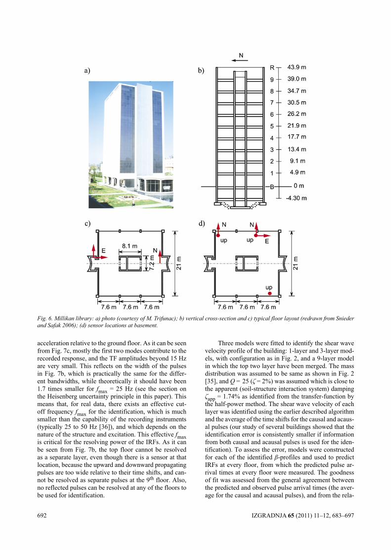
692 IZGRADNJA 65 (2011) 11–12, 683–697
acceleration relative to the ground floor. As it can be seen from Fig. 7c, mostly the first two modes contribute to the recorded response, and the TF amplitudes beyond 15 Hz are very small. This reflects on the width of the pulses in Fig. 7b, which is practically the same for the differ-ent bandwidths, while theoretically it should have been 1.7 times smaller for fmax = 25 Hz (see the section on the Heisenberg uncertainty principle in this paper). This means that, for real data, there exists an effective cut-off frequency fmax for the identification, which is much smaller than the capability of the recording instruments (typically 25 to 50 Hz [36]), and which depends on the nature of the structure and excitation. This effective fmax is critical for the resolving power of the IRFs. As it can be seen from Fig. 7b, the top floor cannot be resolved as a separate layer, even though there is a sensor at that location, because the upward and downward propagating pulses are too wide relative to their time shifts, and can-not be resolved as separate pulses at the 9th floor. Also, no reflected pulses can be resolved at any of the floors to be used for identification.
Three models were fitted to identify the shear wave velocity profile of the building: 1-layer and 3-layer mod-els, with configuration as in Fig. 2, and a 9-layer model in which the top two layer have been merged. The mass distribution was assumed to be same as shown in Fig. 2 [35], and Q = 25 (ζ = 2%) was assumed which is close to the apparent (soil-structure interaction system) damping ζapp = 1.74% as identified from the transfer-function by the half-power method. The shear wave velocity of each layer was identified using the earlier described algorithm and the average of the time shifts for the causal and acaus-al pulses (our study of several buildings showed that the identification error is consistently smaller if information from both causal and acausal pulses is used for the iden-tification). To assess the error, models were constructed for each of the identified β-profiles and used to predict IRFs at every floor, from which the predicted pulse ar-rival times at every floor were measured. The goodness of fit was assessed from the general agreement between the predicted and observed pulse arrival times (the aver-age for the causal and acausal pulses), and from the rela-
Fig. 6. Millikan library: a) photo (courtesy of M. Trifunac); b) vertical cross-section and c) typical floor layout (redrawn from Snieder and Safak 2006); (d) sensor locations at basement.
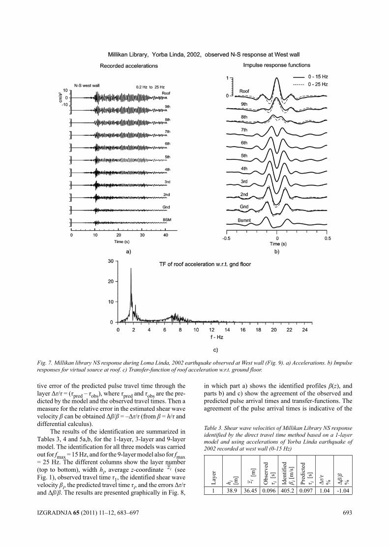
IZGRADNJA 65 (2011) 11–12, 683–697 693
tive error of the predicted pulse travel time through the layer Δτ/τ = (τpred – τobs), where τpred and τobs are the pre-dicted by the model and the observed travel times. Then a measure for the relative error in the estimated shear wave velocity β can be obtained Δβ/β = –Δτ/τ (from β = h/τ and differential calculus).
The results of the identification are summarized in Tables 3, 4 and 5a,b, for the 1-layer, 3-layer and 9-layer model. The identification for all three models was carried out for fmax = 15 Hz, and for the 9-layer model also for fmax = 25 Hz. The different columns show the layer number (top to bottom), width hi, average z-coordinate iz (see Fig. 1), observed travel time τ1, the identified shear wave velocity βi, the predicted travel time τi, and the errors Δτ/τ and Δβ/β. The results are presented graphically in Fig. 8,
in which part a) shows the identified profiles β(z), and parts b) and c) show the agreement of the observed and predicted pulse arrival times and transfer-functions. The agreement of the pulse arrival times is indicative of the
Fig. 7. Millikan library NS response during Loma Linda, 2002 earthquake observed at West wall (Fig. 9). a) Accelerations. b) Impulse responses for virtual source at roof. c) Transfer-function of roof acceleration w.r.t. ground floor.
Table 3. Shear wave velocities of Millikan Library NS response identified by the direct travel time method based on a 1-layer model and using accelerations of Yorba Linda earthquake of 2002 recorded at west wall (0-15 Hz)
Laye
r
h i [m] iz [m
]
Obs
erve
dτ i
[s]
Iden
tifie
d β i [
m/s
]
Pred
icte
dτ i
[s]
Δτ/τ
% Δβ/β
%
1 38.9 36.45 0.096 405.2 0.097 1.04 -1.04
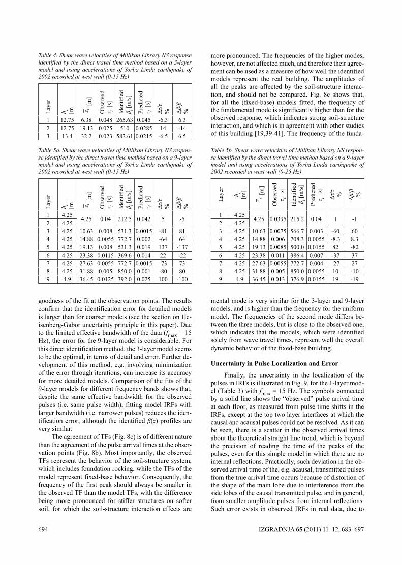
694 IZGRADNJA 65 (2011) 11–12, 683–697
goodness of the fit at the observation points. The results confirm that the identification error for detailed models is larger than for coarser models (see the section on He-isenberg-Gabor uncertainty principle in this paper). Due to the limited effective bandwidth of the data (fmax = 15 Hz), the error for the 9-layer model is considerable. For this direct identification method, the 3-layer model seems to be the optimal, in terms of detail and error. Further de-velopment of this method, e.g. involving minimization of the error through iterations, can increase its accuracy for more detailed models. Comparison of the fits of the 9-layer models for different frequency bands shows that, despite the same effective bandwidth for the observed pulses (i.e. same pulse width), fitting model IRFs with larger bandwidth (i.e. narrower pulses) reduces the iden-tification error, although the identified β(z) profiles are very similar.
The agreement of TFs (Fig. 8c) is of different nature than the agreement of the pulse arrival times at the obser-vation points (Fig. 8b). Most importantly, the observed TFs represent the behavior of the soil-structure system, which includes foundation rocking, while the TFs of the model represent fixed-base behavior. Consequently, the frequency of the first peak should always be smaller in the observed TF than the model TFs, with the difference being more pronounced for stiffer structures on softer soil, for which the soil-structure interaction effects are
more pronounced. The frequencies of the higher modes, however, are not affected much, and therefore their agree-ment can be used as a measure of how well the identified models represent the real building. The amplitudes of all the peaks are affected by the soil-structure interac-tion, and should not be compared. Fig. 8c shows that, for all the (fixed-base) models fitted, the frequency of the fundamental mode is significantly higher than for the observed response, which indicates strong soil-structure interaction, and which is in agreement with other studies of this building [19,39-41]. The frequency of the funda-
Table 5b. Shear wave velocities of Millikan Library NS respon-se identified by the direct travel time method based on a 9-layer model and using accelerations of Yorba Linda earthquake of 2002 recorded at west wall (0-25 Hz)
Laye
r
h i[m
]
iz [m
]
Obs
erve
dτ i
[s]
Iden
tifie
d β i [
m/s
]
Pred
icte
dτ i
[s]
Δτ/τ % Δβ/β %
1 4.254.25 0.0395 215.2 0.04 1 -1
2 4.253 4.25 10.63 0.0075 566.7 0.003 -60 604 4.25 14.88 0.006 708.3 0.0055 -8.3 8.35 4.25 19.13 0.0085 500.0 0.0155 82 -826 4.25 23.38 0.011 386.4 0.007 -37 377 4.25 27.63 0.0055 772.7 0.004 -27 278 4.25 31.88 0.005 850.0 0.0055 10 -109 4.9 36.45 0.013 376.9 0.0155 19 -19
Table 4. Shear wave velocities of Millikan Library NS response identified by the direct travel time method based on a 3-layer model and using accelerations of Yorba Linda earthquake of 2002 recorded at west wall (0-15 Hz)
Laye
r
h i [m] iz [m
]
Obs
erve
dτ i
[s]
Iden
tifie
d β i [
m/s
]
Pred
icte
dτ i
[s]
Δτ/τ
% Δβ/β
%
1 12.75 6.38 0.048 265.63 0.045 -6.3 6.32 12.75 19.13 0.025 510 0.0285 14 -143 13.4 32.2 0.023 582.61 0.0215 -6.5 6.5
Table 5a. Shear wave velocities of Millikan Library NS respon-se identified by the direct travel time method based on a 9-layer model and using accelerations of Yorba Linda earthquake of 2002 recorded at west wall (0-15 Hz)
Laye
r
h i [m] iz [m
]
Obs
erve
dτ i
[s]
Iden
tifie
d β i [
m/s
]
Pred
icte
dτ i
[s]
Δτ/τ
% Δβ/β
%
1 4.254.25 0.04 212.5 0.042 5 -5
2 4.253 4.25 10.63 0.008 531.3 0.0015 -81 814 4.25 14.88 0.0055 772.7 0.002 -64 645 4.25 19.13 0.008 531.3 0.019 137 -1376 4.25 23.38 0.0115 369.6 0.014 22 -227 4.25 27.63 0.0055 772.7 0.0015 -73 738 4.25 31.88 0.005 850.0 0.001 -80 809 4.9 36.45 0.0125 392.0 0.025 100 -100
mental mode is very similar for the 3-layer and 9-layer models, and is higher than the frequency for the uniform model. The frequencies of the second mode differs be-tween the three models, but is close to the observed one, which indicates that the models, which were identified solely from wave travel times, represent well the overall dynamic behavior of the fixed-base building.
Uncertainty in Pulse localization and Error
Finally, the uncertainty in the localization of the pulses in IRFs is illustrated in Fig. 9, for the 1-layer mod-el (Table 3) with fmax = 15 Hz. The symbols connected by a solid line shows the “observed” pulse arrival time at each floor, as measured from pulse time shifts in the IRFs, except at the top two layer interfaces at which the causal and acausal pulses could not be resolved. As it can be seen, there is a scatter in the observed arrival times about the theoretical straight line trend, which is beyond the precision of reading the time of the peaks of the pulses, even for this simple model in which there are no internal reflections. Practically, such deviation in the ob-served arrival time of the, e.g. acausal, transmitted pulses from the true arrival time occurs because of distortion of the shape of the main lobe due to interference from the side lobes of the causal transmitted pulse, and in general, from smaller amplitude pulses from internal reflections. Such error exists in observed IRFs in real data, due to
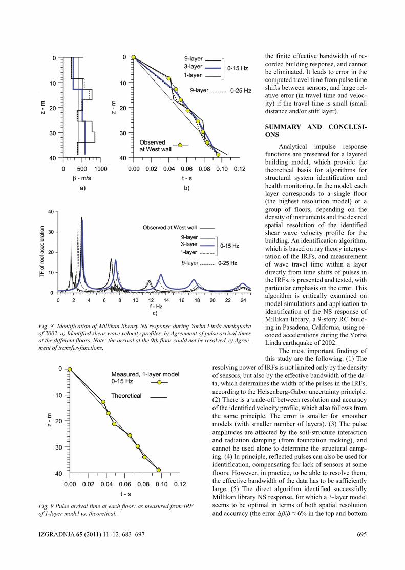
IZGRADNJA 65 (2011) 11–12, 683–697 695
resolving power of IRFs is not limited only by the density of sensors, but also by the effective bandwidth of the da-ta, which determines the width of the pulses in the IRFs, according to the Heisenberg-Gabor uncertainty principle. (2) There is a trade-off between resolution and accuracy of the identified velocity profile, which also follows from the same principle. The error is smaller for smoother models (with smaller number of layers). (3) The pulse amplitudes are affected by the soil-structure interaction and radiation damping (from foundation rocking), and cannot be used alone to determine the structural damp-ing. (4) In principle, reflected pulses can also be used for identification, compensating for lack of sensors at some floors. However, in practice, to be able to resolve them, the effective bandwidth of the data has to be sufficiently large. (5) The direct algorithm identified successfully Millikan library NS response, for which a 3-layer model seems to be optimal in terms of both spatial resolution and accuracy (the error Δβ/β ≈ 6% in the top and bottom
the finite effective bandwidth of re-corded building response, and cannot be eliminated. It leads to error in the computed travel time from pulse time shifts between sensors, and large rel-ative error (in travel time and veloc-ity) if the travel time is small (small distance and/or stiff layer).
SUMMARy AND cONclUSI-ONS
Analytical impulse response functions are presented for a layered building model, which provide the theoretical basis for algorithms for structural system identification and health monitoring. In the model, each layer corresponds to a single floor (the highest resolution model) or a group of floors, depending on the density of instruments and the desired spatial resolution of the identified shear wave velocity profile for the building. An identification algorithm, which is based on ray theory interpre-tation of the IRFs, and measurement of wave travel time within a layer directly from time shifts of pulses in the IRFs, is presented and tested, with particular emphasis on the error. This algorithm is critically examined on model simulations and application to identification of the NS response of Millikan library, a 9-story RC build-ing in Pasadena, California, using re-coded accelerations during the Yorba Linda earthquake of 2002.
The most important findings of this study are the following. (1) The
Fig. 8. Identification of Millikan library NS response during Yorba Linda earthquake of 2002. a) Identified shear wave velocity profiles. b) Agreement of pulse arrival times at the different floors. Note: the arrival at the 9th floor could not be resolved. c) Agree-ment of transfer-functions.
Fig. 9 Pulse arrival time at each floor: as measured from IRF of 1-layer model vs. theoretical.
696 IZGRADNJA 65 (2011) 11–12, 683–697
layers and 14% in the middle layer). (6) The error for the highest resolution model (one story per layer) is large in some of the layers (about 80% in one of the layers).
It is concluded that system identification of build-ings from wave travel times, measured from IRFs, is robust when applied to real building and earthquake re-sponse, and is promising. However, further developments are needed of the presented direct algorithm to increase its accuracy at high resolution. One such development is to include information about the pulse amplitudes, which also depend on the shear wave velocities of the layers, and optimization to minimize the error in all the layers. We will report on the development of such an algorithm, which involves nonlinear least squares fit of pulse shapes simultaneously at all observation points, in a future pub-lication.
REfERENcES
[1] Kanai K. Some new problems of seismic vibrations of a structure, Proc. Third World Conf. Earthquake Eng., Auckland and Wellington, New Zealand, Ja-nuary 22-February 1, 1965, pp. II-260 to II-275.
[2] Todorovska MI, Trifunac MD. Antiplane earthqua-ke waves in long structures, J. Engrg Mech. (ASCE) 1989; 115(12):2687-2708.
[3] Todorovska MI, Lee VW. Seismic waves in buildin-gs with shear walls or central core, J. Engrg Mech. (ASCE) 1989; 115(12):2669-2686.
[4] Todorovska MI, Trifunac MD. A note on the propa-gation of earthquake waves in buildings with soft first floor, J. Engrg Mech. (ASCE) 1990; 116(4):892-900.
[5] Şafak E. Detection of seismic damage in multi-story buildings by using wave propagation analysis. Proc. Sixth U.S. National Conf. on Earthquake Eng. 1989; EERI, Oakland, CA, Paper No. 171, pp. 12.
[6] Şafak E. Wave propagation formulation of seismic response of multi-story buildings. J. Structural Eng. (ASCE) 1990; 125(4):426-437.
[7] Todorovska MI, Ivanovic SS, Trifunac MD. Wave propagation in a seven-story reinforced concrete bu-ilding, Part II: observed wavenumbers, Soil Dyna-mics and Earthquake Engrg 2001:21(3), 224-236.
[8] Kawakami H, Oyunchimeg M. Normalized in-put-output minimization analysis of wave propa-gation in buildings, Engineering Structures 2003; 25(11):1429-1442.
[9] Oyunchimeg M, Kawakami H. A new method for propagation analysis of earthquake waves in dama-ged buildings: Evolutionary Normalized Input-Out-put Minimization (NIOM), J. of Asian Architecture and Building Engineering 2003; 2(1):9-16.
[10] Kawakami H, Oyunchimeg M. Wave propagation modeling analysis of earthquake records for buil-dings. J. of Asian Architecture and Building Engi-neering 2004;3(1):33-40.
[11] Gičev V. Investigation of soil-flexible foundation-structure interaction for incident plane SH waves.
Ph.D. Dissertation, Department of Civil Enginee-ring, University of Southern California, Los Ange-les, CA., 2005.
[12] Snieder R, Şafak E. Extracting the building respon-se using interferometry: theory and applications to the Millikan Library in Pasadena, California, Bull. Seism. Soc. Am. 2006, 96(2):586-598.
[13] Gičev V, Trifunac MD. Permanent deformations and strains in a shear building excited by a strong mo-tion pulse. Soil Dyn. Earthq. Eng. 2007; 27(8):774-792.
[14] Kohler MD, Heaton T, Bradford SC. Propagating Waves in the Steel, Moment-Frame Factor Building Recorded during Earthquakes, Bull. Seism. Soc. Am. 2007; 97(4):1334-1345.
[15] Gičev V, Trifunac MD. Rotations in a shear-beam model of a seven-story building caused by nonlinear waves during earthquake excitation, Struct. Control and Health Monitoring 2009; 16(4): 460-482, DOI: 10.1002/stc.264.
[16] Todorovska MI, Trifunac MD. Earthquake dama-ge detection in the Imperial County Services Buil-ding III: analysis of wave travel times via impulse response functions, Soil Dyn. Earthq. Eng. 2008; 28(5):387–404.
[17] Todorovska MI, Trifunac MD. Impulse response analysis of the Van Nuys 7-story hotel during 11 ear-thquakes and earthquake damage detection, Struct. Control and Health Monitoring 2008; 15(1):90-116.
[18] Todorovska MI. Seismic interferometry of a soil-structure interaction model with coupled horizontal and rocking response, Bull. Seism. Soc. Am. 2009; 99(2A):611-625.
[19] Todorovska MI. Soil-structure system identificati-on of Millikan Library North-South response du-ring four earthquakes (1970-2002): what caused the observed wandering of the system frequencies?, Bull. Seism. Soc. Am. 2009; 99(2A):626-635.
[20] Trifunac MD, Todorovska MI, Manić MI, Bulajić BĐ. Variability of the fixed-base and soil-structure system frequencies of a building – the case of Borik-2 building, Structural Control and Health Monito-ring 2010; 17(2):120–151, DOI: 10.1002/stc.277.
[21] Ivanović SS, Trifunac MD, Todorovska MI. On identification of damage in structures via wave tra-vel times, in M. Erdik, M. Celebi, V. Mihailov, and N. Apaydin (Eds.), Proc. NATO Advanced Resear-ch Workshop on Strong-Motion Instrumentation for Civil Engineering Structures, June 2-5, 1999, Ista-nbul, Turkey, Kluwer Academic Publishers 2001; 447-468.
[22] Gilbert F, Backus GE. Propagator matrices in ela-stic wave and vibration problems, Geophysics 1966; XXXI(2):326-332.
[23] Trampert J, Cara M, Frogneux M. SH propagator matrix and QS estimates from borehole– and surfa-ce-recorded earthquake data, Geophys. J. Int. 1993; 112:290-299.
IZGRADNJA 65 (2011) 11–12, 683–697 697
[24] Mehta K, Snieder R, Graizer V. Extraction of ne-ar-surface properties for a lossy layered medi-um using the propagator matrix, Geophys. J. Int. 2007;169:271-280.
[25] Todorovska MI. Earthquake damage detection in buildings and early warning based on wave travel times, Proceedings of 2009 NSF Engineering Rese-arch and Innovation Conference, Honolulu, Hawaii, June 22-25, 2009, Grant # CMMI-0800399, pp.8, National Science Foundation, Washington, DC.
[26] Aki K, Richards P. Quantitative seismology. Free-man and Company 2002.
[27] Thompson WT. Transmission of elastic waves thro-ugh a stratified solid, J. of Applied Physics 1950; 21:89-93.
[28] Haskell NA. The dispersion of surface waves in multilayered media, Bull. Seism. Soc. Am. 1953; 43:17-34.
[29] Trifunac MD. Q and high frequency strong motion spectra, Soil Dynamics and Earthquake Engrg 1994; 13(3):149-161.
[30] Gabor D. Theory of Communications, J. IEE (Lon-dres), 1946; 93:429-457.
[31] Gabor D. Communication Theory and Physics, IEEE Trans. Info. Theory, 1953, IT-1:48-59.
[32] Todorovska MI, Trifunac MD. Earthquake damage detection in the Imperial County Services Building I: the data and time-frequency analysis, Soil Dyna-mics and Earthquake Engrg 2007; 27(6):564–576.
[33] Trifunac MD. Zero baseline correction of strong-motion accelerograms, Bull. Seism. Soc. Amer. 1971; 61(5):1201-1211.
[34] Trifunac MD. A note on correction of strong-motion accelerograms for instrument response, Bull. Seism. Soc. Am. 1972; 62(1):401-409.
[35] Jennings PC, Kuroiwa JH. Vibration and soil-structu-re interaction tests of a nine-story reinforced concre-te building, Bull. Seism. Soc. Am. 1968;58(3):891-916.
[36] Trifunac MD, Todorovska MI. Evolution of accele-rographs, data processing, strong motion arrays and amplitude and spatial resolution in recording strong earthquake motion, Soil Dynamics and Earthuake Engrg 2001;21(6):537-555.
[37] Udwadia FE, Trifunac MD. Time and amplitude dependent response of structures, Earthquake Engi-neering and Structural Dynamics 1974;2:359-378.
[38] Foutch DA, Luco JE, Trifunac MD, Udwadia FE. Full scale three-dimensional tests of structural de-formations during forced excitation of a nine-story reinforced concrete building, Proc. U.S. National Conf. on Earthquake Engineering, Ann Arbor, Mi-chigan, 1975:206-215.
[39] Luco JE, Trifunac MD, Wong HL. On the apparent change in the dynamic behavior of a nine-story re-inforced concrete building, Bull. Seism. Soc. Am. 1987;77(6):1961-1983.
[40] Wong HL, Trifunac MD, Luco JE. A comparison of soil-structure interaction calculations with results of full-scale forced vibration tests, Soil Dynamics and Earthquake Engineering 1988; 7(1):22-31.
[41] Luco JE, Trifunac MD, Wong HL. Isolation of soil-structure interaction effects by full-scale forced vi-bration tests, Earthquake Engineering and Structural Dynamics 1988; 16: 1-21.
[42] Clinton JF, Bradford SK, Heaton TH, Favela J. The observed wander of the natural frequencies in a structure. Bull. Seism. Soc. Amer.2006; 96(1):237-257.
[43] Todorovska MI, Al Rjoub Y. Environmental effects on measured structural frequencies – model predic-tion of short term shift during heavy rainfall and comparison with full-scale observations, Structural Control and Health Monitoring, 2009; 16(4):406-424, DOI: 10.1002/stc.260.
ACKNOWLEDGEMENTS
This work was supported by a grant from the U.S. National Sci-ence Foundation (CMMI-0800399). The strong motion data used for this study was obtained from the Engineering Center for Strong Mo-tion Data (www.strongmotioncenter.org/). The authors are grateful to two anonymous reviewers, M.D. Trifunac, and F.J. Sanchez-Sesma, whose critical comments on the original submission lead to signifi-cant improvements of this paper.
Submitted for possible publication in SCHM: December 3, 2010
Revision submitted: July 26, 2011
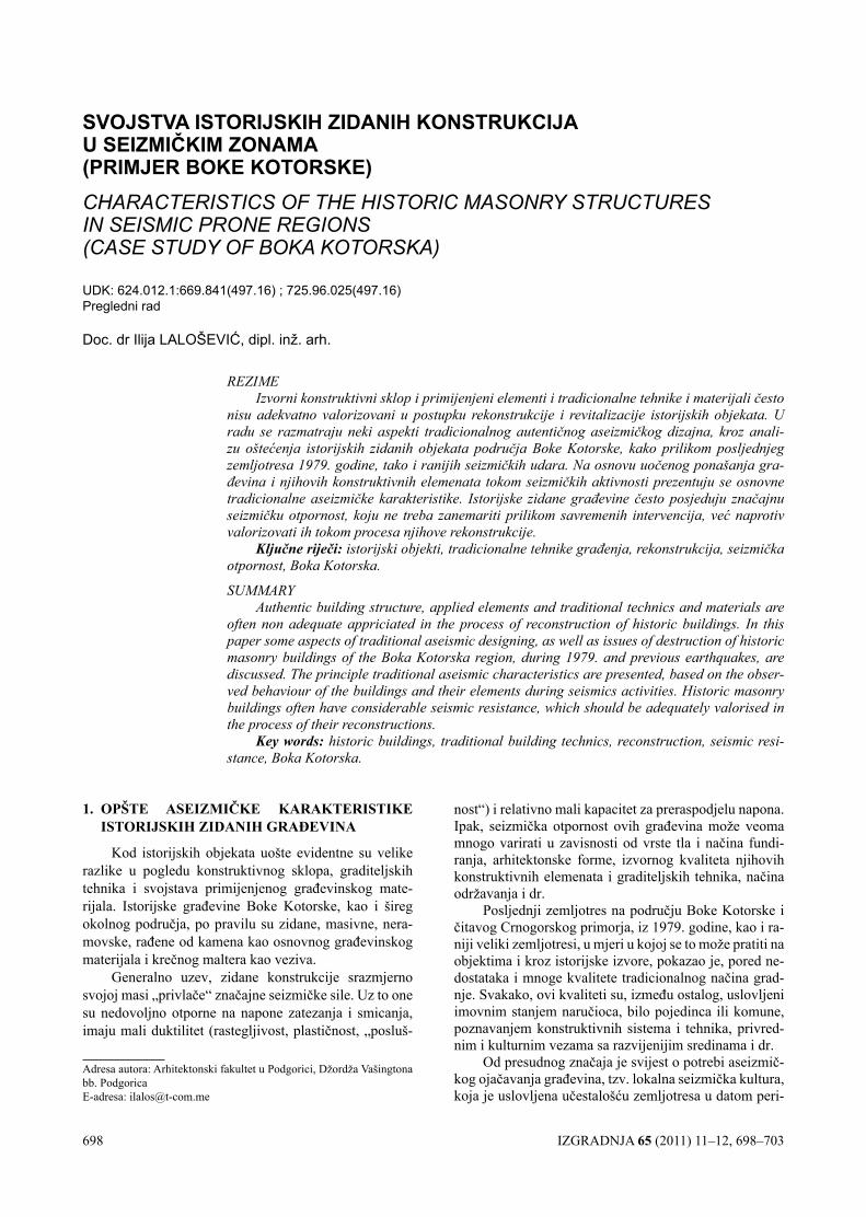
698 IZGRADNJA 65 (2011) 11–12, 698–703
SVOJSTVA ISTORIJSKIH ZIDANIH KONSTRUKCIJA U SEIZMIČKIM ZONAMA (PRIMJER BOKE KOTORSKE)CHARACTERISTICS OF THE HISTORIC MASONRY STRUCTURES IN SEISMIC PRONE REGIONS (CASE STUDY OF BOkA kOTORSkA)
UDK: 624.012.1:669.841(497.16) ; 725.96.025(497.16) Pregledni rad
Doc. dr Ilija LALOŠEVIĆ, dipl. inž. arh.
REZIMEIzvorni konstruktivni sklop i primijenjeni elementi i tradicionalne tehnike i materijali često
nisu adekvatno valorizovani u postupku rekonstrukcije i revitalizacije istorijskih objekata. U radu se razmatraju neki aspekti tradicionalnog autentičnog aseizmičkog dizajna, kroz anali-zu oštećenja istorijskih zidanih objekata područja Boke Kotorske, kako prilikom posljednjeg zemljotresa 1979. godine, tako i ranijih seizmičkih udara. Na osnovu uočenog ponašanja gra-đevina i njihovih konstruktivnih elemenata tokom seizmičkih aktivnosti prezentuju se osnovne tradicionalne aseizmičke karakteristike. Istorijske zidane građevine često posjeduju značajnu seizmičku otpornost, koju ne treba zanemariti prilikom savremenih intervencija, već naprotiv valorizovati ih tokom procesa njihove rekonstrukcije.
Ključne riječi: istorijski objekti, tradicionalne tehnike građenja, rekonstrukcija, seizmička otpornost, Boka Kotorska.
SUMMARYAuthentic building structure, applied elements and traditional technics and materials are
often non adequate appriciated in the process of reconstruction of historic buildings. In this paper some aspects of traditional aseismic designing, as well as issues of destruction of historic masonry buildings of the Boka Kotorska region, during 1979. and previous earthquakes, are discussed. The principle traditional aseismic characteristics are presented, based on the obser-ved behaviour of the buildings and their elements during seismics activities. Historic masonry buildings often have considerable seismic resistance, which should be adequately valorised in the process of their reconstructions.
Key words: historic buildings, traditional building technics, reconstruction, seismic resi-stance, Boka Kotorska.
1. OPŠTE ASEIZMIČKE KARAKTERISTIKE ISTORIjSKIh ZIDANIh gRAĐEVINA
Kod istorijskih objekata uošte evidentne su velike razlike u pogledu konstruktivnog sklopa, graditeljskih tehnika i svojstava primijenjenog građevinskog mate-rijala. Istorijske građevine Boke Kotorske, kao i šireg okolnog područja, po pravilu su zidane, masivne, nera-movske, rađene od kamena kao osnovnog građevinskog materijala i krečnog maltera kao veziva.
Generalno uzev, zidane konstrukcije srazmjerno svojoj masi „privlače“ značajne seizmičke sile. Uz to one su nedovoljno otporne na napone zatezanja i smicanja, imaju mali duktilitet (rastegljivost, plastičnost, „posluš-
nost“) i relativno mali kapacitet za preraspodjelu napona. Ipak, seizmička otpornost ovih građevina može veoma mnogo varirati u zavisnosti od vrste tla i načina fundi-ranja, arhitektonske forme, izvornog kvaliteta njihovih konstruktivnih elemenata i graditeljskih tehnika, načina održavanja i dr.
Posljednji zemljotres na području Boke Kotorske i čitavog Crnogorskog primorja, iz 1979. godine, kao i ra-niji veliki zemljotresi, u mjeri u kojoj se to može pratiti na objektima i kroz istorijske izvore, pokazao je, pored ne-dostataka i mnoge kvalitete tradicionalnog načina grad-nje. Svakako, ovi kvaliteti su, između ostalog, uslovljeni imovnim stanjem naručioca, bilo pojedinca ili komune, poznavanjem konstruktivnih sistema i tehnika, privred-nim i kulturnim vezama sa razvijenijim sredinama i dr.
Od presudnog značaja je svijest o potrebi aseizmič-kog ojačavanja građevina, tzv. lokalna seizmička kultura, koja je uslovljena učestalošću zemljotresa u datom peri-
Adresa autora: Arhitektonski fakultet u Podgorici, Džordža Vašingtona bb. PodgoricaE-adresa: [email protected]
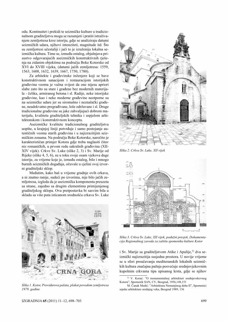
IZGRADNJA 65 (2011) 11–12, 698–703 699
odu. Kontinuitet i prekidi te seizmičke kulture u tradicio-nalnom graditeljstvu mogu se razumjeti i pratiti istraživa-njem zemljotresa kroz istoriju, gdje se analiziraju datumi seizmičkih udara, njihovi intenziteti, magnitude itd. Što su zemljotresi učestaliji i jači to je izraženija lokalna se-izmička kultura. Time se, između ostalog, objašnjava pri-sustvo odgovarajućih aseizmičkih konstruktivnih rješe-nja na zidanim objektima na području Boke Kotorske od XVI do XVIII vijeka, (datumi jačih zemljotresa: 1559, 1563, 1608, 1632, 1639, 1667, 1750, 1780).
Za arhitekte i građevinske inženjere koji se bave konstruktivnom sanacijom i restauracijom istorijskih građevina veoma je važna svijest da one nijesu apriori slabe zato što su stare i građene bez modernih materija-la - čelika, armiranog betona i sl. Radije, neke istorijske građevine, kao i neke moderne građevine neotporne su na seizmičke udare jer su siromašno i neznalački građe-ne, neadekvatno pregrađivane, loše održavane i sl. Druge tradicionalne građevine su jake zahvaljujući dobrom ma-terijalu, kvalitetu graditeljskih tehnika i uspjelom arhi-tektonskom i konstruktivnom konceptu.
Aseizmičke kvalitete tradicionalnog graditeljstva uopšte, u krajnjoj liniji potvrđuje i samo postojanje au-tentičnih veoma starih građevina i u najizrazitijim seiz-mičkim zonama. Na području Boke Kotorske, naročito je karakterističan primjer Kotora gdje treba naglasiti čitav niz romaničkih, u prvom redu sakralnih građevina (XII-XIV vijek). Crkve Sv. Luke (slike 2, 3) i Sv. Marije od Rijeke (slike 4, 5, 6), su u toku svoje osam vjekova duge istorije, za vrijeme koje je, između ostalog, bilo i mnogo burnih seizmičkih događaja, očuvale u cjelini svoj izvor-ni graditeljski sklop.
Međutim, kako baš u vrijeme gradnje ovih crkava, a ni znatno ranije, sudeći po izvorima, nije bilo jačih ze-mljotresa, izgleda da je aseizmička komponenta preuzeta sa strane, zajedno sa drugim elementima primijenjenog graditeljskog sklopa. Ova pretpostavka bi sasvim bila u skladu sa više puta isticanom srodnošću crkava Sv. Luke
i Sv. Marije sa graditeljstvom Atike i Apulije,1) dva se-izmički najizrazitija susjedna prostora. U novije vrijeme se u sferi proučavanja mediteranskih lokalnih seizmič-kih kultura značajna pažnja posvećuje srednjovjekovnim kupolnim crkvama tipa upisanog krsta, gdje se njihov
1) V. Korać: ”O monumentalnoj arhitekturi srednjevekovnog Kotora”, Spomenik SAN, CV, Beograd, 1956,148,151
M. Čanak Medić: ”Arhitektura Nemanjinog doba II”, Spomenici srpske arhitekture srednjeg veka, Beograd 1989, 136
Slika 1. Kotor, Providurova palata, plakat povodom zemljotresa 1979. godine
Slika 2. Crkva Sv. Luke, XII vijek
Slika 3. Crkva Sv. Luke, XII vijek, podužni presjek, Dokumenta-cija Regionalnog zavoda za zaštitu spomenika kulture Kotor
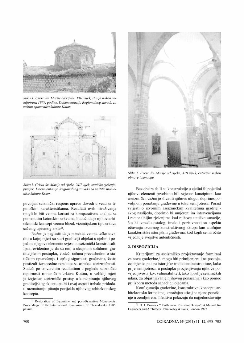
700 IZGRADNJA 65 (2011) 11–12, 698–703
povoljan seizmički respons upravo dovodi u vezu sa ti-pološkim karakteristikama. Rezultati ovih istraživanja mogli bi biti veoma korisni za komparativnu analizu sa pomenutim kotorskim crkvama, budući da je njihov arhi-tektonski koncept veoma blizak vizantijskom tipu crkava sažetog upisanog krsta2).
Nužno je naglasiti da je ponekad veoma teško utvr-diti u kojoj mjeri su stari graditelji objekat u cjelini i po-jedine njegove elemente svjesno aseizmički konstruisali. Ipak, evidentno je da su oni, u ukupnom solidnom gra-diteljskom postupku, vodeći računa prevashodno o sta-tičkom opterećenju i opštoj sigurnosti građevine, često postizali izvanredne rezultate sa aspekta aseizmičnosti. Sudeći po ostvarenim rezultatima u pogledu seizmičke otpornosti romaničkih crkava Kotora, u velikoj mjeri je izvjestan aseizmički pristup u koncipiranju njihovog graditeljskog sklopa, pa bi i ovaj aspekt trebalo pridoda-ti razmatranju pitanja porijekla njihovog arhitektonskog koncepta.
2) Restoration of Byzantine and post-Byzantine Monuments, Proceedings of the International Symposium of Thessaloniki, 1985.passim
Bez obzira da li su konstrukcije u cjelini ili pojedini njihovi elementi prvobitno bili svjesno koncipirani kao aseizmički, važno je shvatiti njihovu ulogu i doprinos po-voljnom ponašanju građevine u toku zemljotresa. Porast svijesti o izvornim aseizmičkim kvalitetima graditelj-skog naslijeđa, doprinio bi umjerenijim intervencijama i racionalnijim rješenjima kod njihove statičke sanacije, što bi između ostalog, imalo i pozitivnosti sa aspekta očuvanja izvornog konstruktivnog sklopa kao značajne karakteristike istorijskih građevina, kod kojih se naročito vrjednuje svojstvo autentičnosti.
2. DISPOZIcIjA
Kriterijumi za aseizmičko projektovanje formirani za nove građevine,3) mogu biti primijenjeni i na postoje-će objekte, pa i na istorijske tradicionalne strukture, kako prije zemljotresa, u postupku procjenjivanja njihove po-vrjedljivosti (tzv. vulnerabilitet), tako i poslije seizmičkih udara, za objašnjavanje njihovog ponašanja i kao pomoć pri izboru metoda sanacije i ojačanja.
Konfiguracija građevine, konstruktivni koncept i ar-hitektonska forma imaju značajan uticaj na njeno ponaša-nje u zemljotresu. Iskustva pokazuju da najjednostavnije
3) D. J. Dowrick:“ Earthquake Resistant Design“, A Manual for Engineers and Architects, John Wiley & Sons, London 1977.
Slika 4. Crkva Sv. Marije od rijeke, XIII vijek, stanje nakon ze-mljotresa 1979. godine, Dokumentacija Regionalnog zavoda za zaštitu spomenika kulture Kotor
Slika 5. Crkva Sv. Marije od rijeke, XIII vijek, statičko rješenje, presjek, Dokumentacija Regionalnog zavoda za zaštitu spome-nika kulture Kotor
Slika 6. Crkva Sv. Marije od rijeke, XIII vijek, enterijer nakon obnove i sanacije
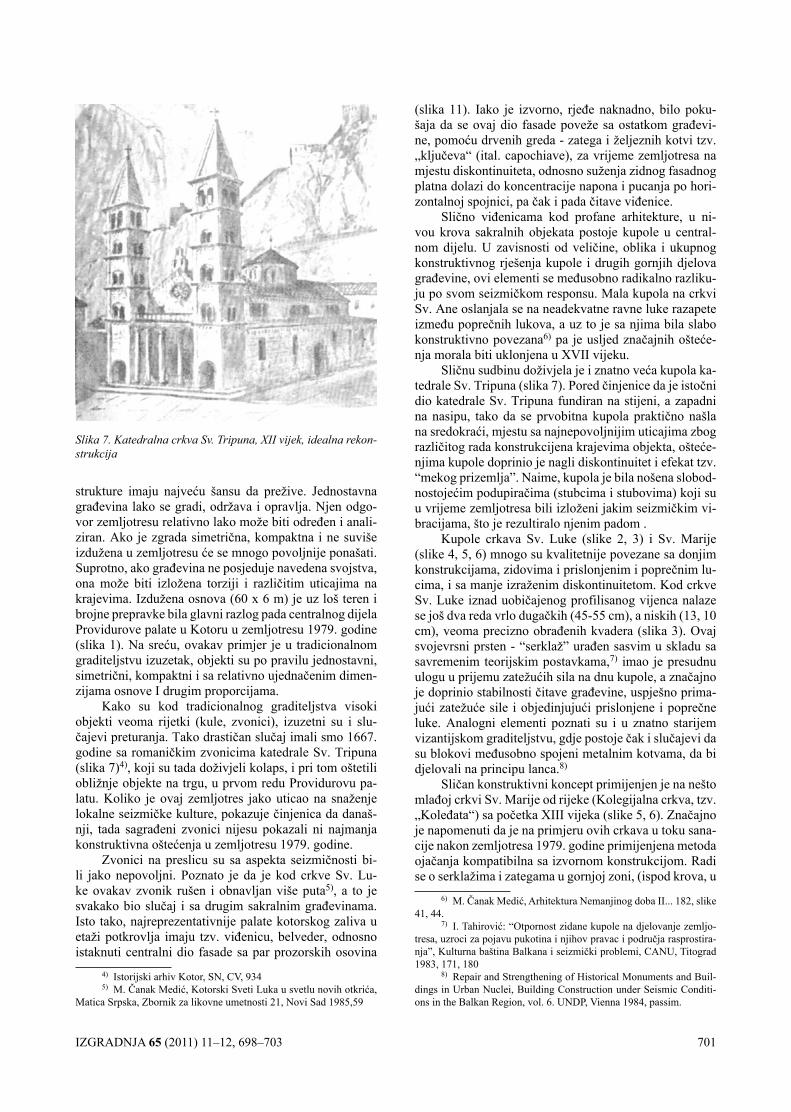
IZGRADNJA 65 (2011) 11–12, 698–703 701
strukture imaju najveću šansu da prežive. Jednostavna građevina lako se gradi, održava i opravlja. Njen odgo-vor zemljotresu relativno lako može biti određen i anali-ziran. Ako je zgrada simetrična, kompaktna i ne suviše izdužena u zemljotresu će se mnogo povoljnije ponašati. Suprotno, ako građevina ne posjeduje navedena svojstva, ona može biti izložena torziji i različitim uticajima na krajevima. Izdužena osnova (60 x 6 m) je uz loš teren i brojne prepravke bila glavni razlog pada centralnog dijela Providurove palate u Kotoru u zemljotresu 1979. godine (slika 1). Na sreću, ovakav primjer je u tradicionalnom graditeljstvu izuzetak, objekti su po pravilu jednostavni, simetrični, kompaktni i sa relativno ujednačenim dimen-zijama osnove I drugim proporcijama.
Kako su kod tradicionalnog graditeljstva visoki objekti veoma rijetki (kule, zvonici), izuzetni su i slu-čajevi preturanja. Tako drastičan slučaj imali smo 1667. godine sa romaničkim zvonicima katedrale Sv. Tripuna (slika 7)4), koji su tada doživjeli kolaps, i pri tom oštetili obližnje objekte na trgu, u prvom redu Providurovu pa-latu. Koliko je ovaj zemljotres jako uticao na snaženje lokalne seizmičke kulture, pokazuje činjenica da današ-nji, tada sagrađeni zvonici nijesu pokazali ni najmanja konstruktivna oštećenja u zemljotresu 1979. godine.
Zvonici na preslicu su sa aspekta seizmičnosti bi-li jako nepovoljni. Poznato je da je kod crkve Sv. Lu-ke ovakav zvonik rušen i obnavljan više puta5), a to je svakako bio slučaj i sa drugim sakralnim građevinama. Isto tako, najreprezentativnije palate kotorskog zaliva u etaži potkrovlja imaju tzv. viđenicu, belveder, odnosno istaknuti centralni dio fasade sa par prozorskih osovina
4) Istorijski arhiv Kotor, SN, CV, 9345) M. Čanak Medić, Kotorski Sveti Luka u svetlu novih otkrića,
Matica Srpska, Zbornik za likovne umetnosti 21, Novi Sad 1985,59
(slika 11). Iako je izvorno, rjeđe naknadno, bilo poku-šaja da se ovaj dio fasade poveže sa ostatkom građevi-ne, pomoću drvenih greda - zatega i željeznih kotvi tzv. „ključeva“ (ital. capochiave), za vrijeme zemljotresa na mjestu diskontinuiteta, odnosno suženja zidnog fasadnog platna dolazi do koncentracije napona i pucanja po hori-zontalnoj spojnici, pa čak i pada čitave viđenice.
Slično viđenicama kod profane arhitekture, u ni-vou krova sakralnih objekata postoje kupole u central-nom dijelu. U zavisnosti od veličine, oblika i ukupnog konstruktivnog rješenja kupole i drugih gornjih djelova građevine, ovi elementi se međusobno radikalno razliku-ju po svom seizmičkom responsu. Mala kupola na crkvi Sv. Ane oslanjala se na neadekvatne ravne luke razapete između poprečnih lukova, a uz to je sa njima bila slabo konstruktivno povezana6) pa je usljed značajnih ošteće-nja morala biti uklonjena u XVII vijeku.
Sličnu sudbinu doživjela je i znatno veća kupola ka-tedrale Sv. Tripuna (slika 7). Pored činjenice da je istočni dio katedrale Sv. Tripuna fundiran na stijeni, a zapadni na nasipu, tako da se prvobitna kupola praktično našla na sredokraći, mjestu sa najnepovoljnijim uticajima zbog različitog rada konstrukcijena krajevima objekta, ošteće-njima kupole doprinio je nagli diskontinuitet i efekat tzv. “mekog prizemlja”. Naime, kupola je bila nošena slobod-nostojećim podupiračima (stubcima i stubovima) koji su u vrijeme zemljotresa bili izloženi jakim seizmičkim vi-bracijama, što je rezultiralo njenim padom .
Kupole crkava Sv. Luke (slike 2, 3) i Sv. Marije (slike 4, 5, 6) mnogo su kvalitetnije povezane sa donjim konstrukcijama, zidovima i prislonjenim i poprečnim lu-cima, i sa manje izraženim diskontinuitetom. Kod crkve Sv. Luke iznad uobičajenog profilisanog vijenca nalaze se još dva reda vrlo dugačkih (45-55 cm), a niskih (13, 10 cm), veoma precizno obrađenih kvadera (slika 3). Ovaj svojevrsni prsten - “serklaž” urađen sasvim u skladu sa savremenim teorijskim postavkama,7) imao je presudnu ulogu u prijemu zatežućih sila na dnu kupole, a značajno je doprinio stabilnosti čitave građevine, uspješno prima-jući zatežuće sile i objedinjujući prislonjene i poprečne luke. Analogni elementi poznati su i u znatno starijem vizantijskom graditeljstvu, gdje postoje čak i slučajevi da su blokovi međusobno spojeni metalnim kotvama, da bi djelovali na principu lanca.8)
Sličan konstruktivni koncept primijenjen je na nešto mlađoj crkvi Sv. Marije od rijeke (Kolegijalna crkva, tzv. „Koleđata“) sa početka XIII vijeka (slike 5, 6). Značajno je napomenuti da je na primjeru ovih crkava u toku sana-cije nakon zemljotresa 1979. godine primijenjena metoda ojačanja kompatibilna sa izvornom konstrukcijom. Radi se o serklažima i zategama u gornjoj zoni, (ispod krova, u
6) M. Čanak Medić, Arhitektura Nemanjinog doba II... 182, slike 41, 44.
7) I. Tahirović: “Otpornost zidane kupole na djelovanje zemljo-tresa, uzroci za pojavu pukotina i njihov pravac i područja rasprostira-nja”, Kulturna baština Balkana i seizmički problemi, CANU, Titograd 1983, 171, 180
8) Repair and Strengthening of Historical Monuments and Buil-dings in Urban Nuclei, Building Construction under Seismic Conditi-ons in the Balkan Region, vol. 6. UNDP, Vienna 1984, passim.
Slika 7. Katedralna crkva Sv. Tripuna, XII vijek, idealna rekon-strukcija
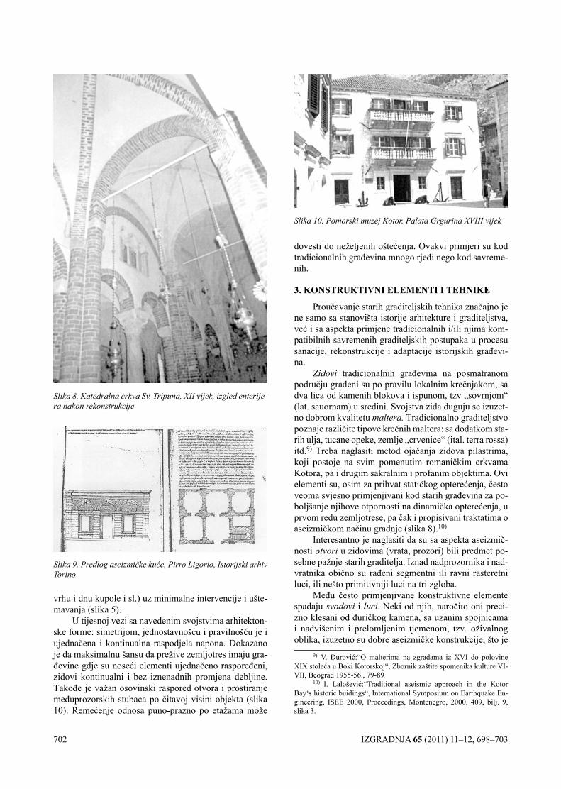
702 IZGRADNJA 65 (2011) 11–12, 698–703
vrhu i dnu kupole i sl.) uz minimalne intervencije i ušte-mavanja (slika 5).
U tijesnoj vezi sa navedenim svojstvima arhitekton-ske forme: simetrijom, jednostavnošću i pravilnošću je i ujednačena i kontinualna raspodjela napona. Dokazano je da maksimalnu šansu da prežive zemljotres imaju gra-đevine gdje su noseći elementi ujednačeno raspoređeni, zidovi kontinualni i bez iznenadnih promjena debljine. Takođe je važan osovinski raspored otvora i prostiranje međuprozorskih stubaca po čitavoj visini objekta (slika 10). Remećenje odnosa puno-prazno po etažama može
dovesti do neželjenih oštećenja. Ovakvi primjeri su kod tradicionalnih građevina mnogo rjeđi nego kod savreme-nih.
3. KONSTRUKTIVNI ElEMENTI I TEhNIKE
Proučavanje starih graditeljskih tehnika značajno je ne samo sa stanovišta istorije arhitekture i graditeljstva, već i sa aspekta primjene tradicionalnih i/ili njima kom-patibilnih savremenih graditeljskih postupaka u procesu sanacije, rekonstrukcije i adaptacije istorijskih građevi-na.
Zidovi tradicionalnih građevina na posmatranom području građeni su po pravilu lokalnim krečnjakom, sa dva lica od kamenih blokova i ispunom, tzv „sovrnjom“ (lat. sauornam) u sredini. Svojstva zida duguju se izuzet-no dobrom kvalitetu maltera. Tradicionalno graditeljstvo poznaje različite tipove krečnih maltera: sa dodatkom sta-rih ulja, tucane opeke, zemlje „crvenice“ (ital. terra rossa) itd.9) Treba naglasiti metod ojačanja zidova pilastrima, koji postoje na svim pomenutim romaničkim crkvama Kotora, pa i drugim sakralnim i profanim objektima. Ovi elementi su, osim za prihvat statičkog opterećenja, često veoma svjesno primjenjivani kod starih građevina za po-boljšanje njihove otpornosti na dinamička opterećenja, u prvom redu zemljotrese, pa čak i propisivani traktatima o aseizmičkom načinu gradnje (slika 8).10)
Interesantno je naglasiti da su sa aspekta aseizmič-nosti otvori u zidovima (vrata, prozori) bili predmet po-sebne pažnje starih graditelja. Iznad nadprozornika i nad-vratnika obično su rađeni segmentni ili ravni rasteretni luci, ili nešto primitivniji luci na tri zgloba.
Među često primjenjivane konstruktivne elemente spadaju svodovi i luci. Neki od njih, naročito oni preci-zno klesani od đuričkog kamena, sa uzanim spojnicama i nadvišenim i prelomljenim tjemenom, tzv. oživalnog oblika, izuzetno su dobre aseizmičke konstrukcije, što je
9) V. Đurović:“O malterima na zgradama iz XVI do polovine XIX stoleća u Boki Kotorskoj“, Zbornik zaštite spomenika kulture VI-VII, Beograd 1955-56., 79-89
10) I. Lalošević:“Traditional aseismic approach in the Kotor Bay‘s historic buidings“, International Symposium on Earthquake En-gineering, ISEE 2000, Proceedings, Montenegro, 2000, 409, bilj. 9, slika 3.
Slika 8. Katedralna crkva Sv. Tripuna, XII vijek, izgled enterije-ra nakon rekonstrukcije
Slika 9. Predlog aseizmičke kuće, Pirro Ligorio, Istorijski arhiv Torino
Slika 10. Pomorski muzej Kotor, Palata Grgurina XVIII vijek
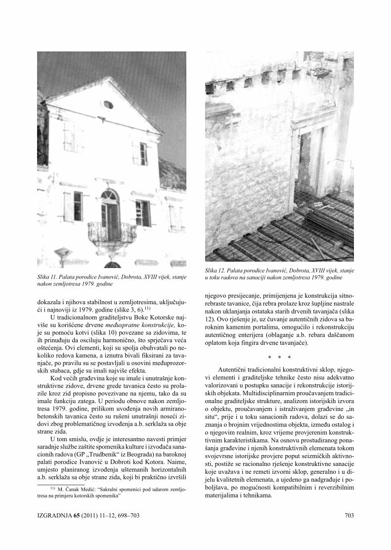
IZGRADNJA 65 (2011) 11–12, 698–703 703
dokazala i njihova stabilnost u zemljotresima, uključuju-ći i najnoviji iz 1979. godine (slike 3, 6).11)
U tradicionalnom graditeljstvu Boke Kotorske naj-više su korišćene drvene međuspratne konstrukcije, ko-je su pomoću kotvi (slika 10) povezane sa zidovima, te ih prinuđuju da osciluju harmonično, što sprječava veća oštećenja. Ovi elementi, koji su spolja obuhvatali po ne-koliko redova kamena, a iznutra bivali fiksirani za tava-njače, po pravilu su se postavljali u osovini međuprozor-skih stubaca, gdje su imali najviše efekta.
Kod većih građevina koje su imale i unutrašnje kon-struktivne zidove, drvene grede tavanica često su prola-zile kroz zid propisno povezivane na njemu, tako da su imale funkciju zatega. U periodu obnove nakon zemljo-tresa 1979. godine, prilikom uvođenja novih armirano-betonskih tavanica često su rušeni unutrašnji noseći zi-dovi zbog problematičnog izvođenja a.b. serklaža sa obje strane zida.
U tom smislu, ovdje je interesantno navesti primjer saradnje službe zaštite spomenika kulture i izvođača sana-cionih radova (GP „Trudbenik“ iz Beograda) na baroknoj palati porodice Ivanović u Dobroti kod Kotora. Naime, umjesto planiranog izvođenja uštemanih horizontalnih a.b. serklaža sa obje strane zida, koji bi praktično izvršili
11) M. Čanak Medić: “Sakralni spomenici pod udarom zemljo-tresa na primjeru kotorskih spomenika”
njegovo presijecanje, primijenjena je konstrukcija sitno-rebraste tavanice, čija rebra prolaze kroz šupljine nastrale nakon uklanjanja ostataka starih drvenih tavanjača (slika 12). Ovo rješenje je, uz čuvanje autentičnih zidova sa ba-roknim kamenim portalima, omogućilo i rekonstrukciju autentičnog enterijera (oblaganje a.b. rebara daščanom oplatom koja fingira drvene tavanjače).
* * *
Autentični tradicionalni konstruktivni sklop, njego-vi elementi i graditeljske tehnike često nisu adekvatno valorizovani u postupku sanacije i rekonstrukcije istorij-skih objekata. Multidisciplinarnim proučavanjem tradici-onalne graditeljske strukture, analizom istorijskih izvora o objektu, proučavanjem i istraživanjem građevine „in situ“, prije i u toku sanacionih radova, dolazi se do sa-znanja o brojnim vrijednostima objekta, između ostalog i o njegovim realnim, kroz vrijeme provjerenim konstruk-tivnim karakteristikama. Na osnovu prostudiranog pona-šanja građevine i njenih konstruktivnih elemenata tokom svojevrsne istorijske provjere poput seizmičkih aktivno-sti, postiže se racionalno rješenje konstruktivne sanacije koje uvažava i ne remeti izvorni sklop, generalno i u di-jelu kvalitetnih elemenata, a ujedeno ga nadgrađuje i po-boljšava, po mogućnosti kompatibilnim i reverzibilnim materijalima i tehnikama.
Slika 11. Palata porodice Ivanović, Dobrota, XVIII vijek, stanje nakon zemljotresa 1979. godine
Slika 12. Palata porodice Ivanović, Dobrota, XVIII vijek, stanje u toku radova na sanaciji nakon zemljotresa 1979. godine
704 IZGRADNJA 65 (2011) 9–10, 704–709
određivanjem promena ovih parametara kroz vreme [2]. Navedena definicija se najčešće citira u literaturi ali se u praksi geodezija primenjuje uvek kada treba određivati koordinate tačaka u prostoru, geometriju objekata, me-đusobne odnose objekata u prostoru i promene geometri-je, položaja i međusobnih odnosa objekata kao funkcije vremena. Razvoj geodezije uslovljavao je obim i vrstu
1. UVOD
Geodezija je nauka koja se bavi određivanjem obli-ka i veličine Zemlje, Zemljinog gravitacionog polja i
PRIMENA GEODEZIJE U ISTRAŽIVANJU UTICAJA SEIZMIČKIH PROCESA NA TLO I INŽENJERSKE STRUKTUREGEODESY UTILIZATION FOR DETERMINATION SEISMIC PROCESSES INFLUENCE ON LAND SURFACE AND ENGINEERING STRUCTURE
UDK: 528.41:550.34 Pregledni rad
Prof. dr Milan TRIFKOVIĆ, dipl.geod.inž.
REZIMEGeodezija kao nauka koja se bavi istraživanjem veličine, oblika i gravitacionog polja Zemlje
kao i promena vrednosti ovih parametara kroz vreme postala je nezaobilazan činilac svih savremenih istraživanja seizmičkih procesa. Pored seizmičkih i geoloških merenja podaci o promenama geometri-je neophodni su za donošenje pouzdanih zaključaka o uticaju seizmičkih procesa na tlo i inženjerske strukture. Do ekspanzije primene geodezije u istraživanju uticaja seizmičkih procesa došlo je kada je tehnologija globalnog pozicioniranja omogućila postizanje visoke tačnosti u određivanju položaja tačaka. Razvoj tehnologije globalnog pozicioniranja omogućio je efikasno postizanje visoke tačno-sti merenja i određivanja položaja tačaka u prostoru što je omogućilo da se otkriju relativno mala pomeranja tačaka na velikim rastojanjima. Na ovaj način je omogućeno praćenje promena položaja tačaka koje mogu nastati kao posledica uticaja seizmičkih procesa. Drugi aspekt uticaja seizmičkih procesa odnosi se na inženjerske strukture i mogućnosti primene geodezije za istraživanje uticaja seizmičkih procesa na različite tipove objekata. Naime uporedo sa razvojem tehnologije globalnog pozicioniranja razvijana je i klasična (terestrička) geodetska tehnologija kako u pogledu tačnosti i pouzdanosti tako i u pogledu efikasnosti dobijanja rezultata merenja. Ove činjenice stvorile su uslove za primenu geodezije u istraživanju uticaja seizmičkih procesa na tlo i inženjerske strukture.
Pregledom dostupne literature autor ovog rada zaključio je da se pitanjima primene geodezije za istraživanje uticaja seizmičkih procesa na tlo i inženjerske strukture u Srbiji ne posvećuje odgova-rajuća pažnja i da je potrebno stručnoj javnosti ukazati na tu činjenicu.
Ključne reči: seizmički procesi, geodezija, geodetske tehnologije.
SUMMARYGeodesy as scientific discipline concerned with the size and shape of the Earth, the Earth’s
gravity field, and the time variations of all these parameters become a standard part of research programs for seismic processes. Along with seismic and geologic, data about geometric changes are needed for accurate and reliable conclusions about seismic processes influence on Earth’s surface and engineering structures. With development, global position system (GPS) reached accuracy and efficiency needed for its utilization in seismic processes research. The other aspect of geodesy uti-lization is concerned with seismic processes influence on engineering structures. Namely, classical geodetic technology was also developed and reached high accuracy and efficiency.
Author of this paper, according to available literature and his own experience, has concluded that those questions are underestimated in Serbia and there is need for discussing those questions according to available literature and experience all over the World.
Key words: seismic processes, geodesy, geodetic technologies.
Adresa autora: Univerzitet u Novom Sadu, Građevinski fakultet, 24000 Subotica, Kozaračka 2aE-mail: [email protected]
IZGRADNJA 65 (2011) 9–10, 704–709 705
primene geodezije u drugim inženjerskim oblastima i za rešavanje različitih inženjerskih problema. U početku svoga razvoja geodetska tehnologija nije bila dovoljno efikasna i nije mogla da postigne zahtevanu tačnost da bi našla adekvatnu primenu u inženjerskim oblastima koje su imale potrebu da koriste geodetske podatke za istraživanje predmetnih prirodnih fenomena. Druga pre-preka za primenu geodezije u istraživanju složenih pri-rodnih fenomena bila je nedovoljan nivo razvijenosti metodologije i tehnologije za obradu i analizu rezultata geodetskih merenja [15]. Razvojem geodetske merne tehnologije, metodologije za obradu i analizu podataka i računarske tehnike rešen je najveći deo problema veza-nih za efikasnost i nivo tačnosti geodetskih podataka. U literaturi [22] eksplicitno se naglašava da je „unapređe-nje geodetskih instrumenata i mernih tehnika u posled-njoj dekadi učinilo upotrebljivim utvrđivanje pomeranja Zemljine kore u razumno kratkim intervalima“. Treba imati u vidu da je ova konstatacija izvedena 1981. godine i da se razvoj geodetskih instrumenata i mernih tehnika nastavio još ubrzanijim tempom. Time je geodezija ste-kla status naučne discipline čiji su podaci nezaobilazni u skoro svim istraživanjima prirodnih fenomena koji za posledicu imaju promenu geometrije Zemljine površi ili promenu geometrije inženjerskih struktura.
Seizmologija se definiše kao nauka koja se bavi istraživanjem mehaničkih vibracija Zemlje [20]. Među-tim ova definicija nije dovoljna da obuhvati sve aspekte i posledice fenomena mehaničkih vibracija Zemlje pa se u literaturi [19] navodi definicija istih autora iz 1980. godine i konstatuje da „savremeni trendovi u seizmolo-giji imaju tendenciju da prevaziđu aspekte povezane sa nastajanjem i prostiranjem seizmičkih talasa“. Očigled-no je iz navedenih citata da je fenomen kojim se bavi seizmologija dosta složen i da se njegovo razumevanje razvija sa novim saznanjima kao i da se razvija potreba za merenjem posledica ovog fenomena.
U savremenoj literaturi i praksi neodvojiva su se-izmička, geološka i geodetska merenja za pravilno tu-mačenje uticaja mehaničkih vibracija Zemlje na tlo i in-ženjerske strukture. Autor ovog rada smatra da se ovim pitanjima ne posvećuje dovoljno pažnje u Srbiji i da je neophodno da se stručna i naučna javnost upozna i poč-ne aktivno da bavi navedenim pitanjima. Iz tog razloga predmet ovog rada predstavlja prikaz aktuelnih pitanja, aktuelne problematike i pojedinih projekata koji imaju za cilj da utvrde uticaj seizmičkih procesa na tlo i inženjer-ske strukture. Takođe se prikazuju i savremene geodet-ske tehnologije koje po svojim karakteristikama zadovo-ljavaju stroge zahteve za utvrđivanje promena geometrije tla i inženjerskih struktura u pogledu tačnosti i brzine do-bijanja traženih podataka.
Razvoj optimizacije projektovanja i deformacione analize geodetskih mreža takođe je od velikog značaja za otkrivanje pomeranja tla i promene geometrije inženjer-skih struktura. Sistematizovan prikaz metoda optimizaci-je projektovanja geodetskih mreža dat je u literaturi [10] dok je sistematizovan prikaz metoda za deformacionu analizu geodetskih mreža dat u literaturi [12].
Značaj optimizacije projektovanja geodetskih mreža ogleda se u povećanju efikasnosti realizacije geodetskih merenja i dostizanju zahtevane tačnosti traženih veliči-na. To konkretno znači da se već u fazi projektovanja geodetskih mreža može osigurati otkrivanje unapred za-date veličine pomeranja geodetskih tačaka uz minimalan obim geodetskih radova.
Značaj deformacione analize geodetskih mreža ogle-da se u mogućnosti da se otkriju tačke koje su promenile položaj i da se otkrije veličina tog pomeranja. To znači da stručnjaci koji analiziraju uticaj seizmičkih procesa na tlo i inženjerske strukture mogu raspolagati sa konkret-nim veličinama promena položaja i međusobnih odnosa tačaka kao ulaznim podacima za svoje analize.
2. gEODETSKE TEhNOlOgIjE
Poslednjih decenija dvadesetog veka i početkom dvadesetprvog veka došlo je do ubrzanog razvoja geodet-skih tehnologija u smeru povećanja njihove efikasnosti i tačnosti rezultata merenja. Uporedo je razvoj računarske tehnike omogućio povećanu efikasnost obrade geodet-skih podataka. Na taj način stvorene su mogućnosti da se vrše masovna geodetska merenja i da se u relativno kratkom roku dobiju rezultati. To je omogućilo primenu geodezije u različitim inženjerskim oblastima i povećalo kvalitet zaključivanja o različitim uticajima koji za posle-dicu imaju promenu položaja tačaka na Zemljinoj površi ili promenu geometrije i položaja inženjerskih struktura. Povećana tačnost rezultata merenja ima za direktnu po-sledicu otkrivanje manjih promena u položaju tačaka na Zemljinoj površi i otkrivanje malih promena u geometriji inženjerskih struktura. Istovremeno, povećana efikasnost merenja i obrade rezultata merenja omogućila je da se zaključci o uticaju seizmičkih procesa na tlo i inženjerske strukture dobiju
U ovom radu će se ukratko opisati geodetske tehno-logije koje se mogu koristiti za otkrivanje promene po-ložaja tačaka na Zemljinoj površi i promene geometrije inženjerskih struktura i njihove karakteristike. Geodetske tehnologije mogu se klasifikovati na sledeći način:
– Klasične terestričke geodetske tehnologije (ge-odetski instrumenti koji se koriste u triangulaciji, trila-teraciji i nivelmanskim mrežama kao što su: teodoliti, elektrooptički daljinomeri, automatske i klasične totalne stanice, oprema za nivelman i sl.)
– Geodetske tehnologije koje se baziraju na prime-ni satelitskih tehnologija (globalno pozicioniranje, VL-BI, InSAR)
– Geodetske tehnologije koje se baziraju na prime-ni fotogrametrijskih snimaka,
– Geodetske tehnologije koje se baziraju na laser-skom skeniranju i
– Geodetske tehnologije specijalno dizajnirane za primenu u industriji.
Iako klasifikacija geodetskih tehnologija može bi-ti koncipirana drugačije ova klasifikacija je prilagođena primeni geodezije u istraživanju uticaja seizmičkih pro-cesa na tlo i inženjerske strukture.
706 IZGRADNJA 65 (2011) 9–10, 704–709
Kada se istražuju uticaji seizmičkih procesa na tlo primenjuju se geodetske tehnologije koje omogućavaju dobijanje rezultata merenja visoke tačnosti na velikim rastojanjima odnosno na velikim površinama koje obu-hvataju teritorije države [35] ili regiona [4], dok se kod istraživanja uticaja seizmičkih procesa na inženjerske strukture zahteva izuzetno visoka tačnost rezultata mere-nja na malim područjima.
2.1. Klasična geodetska terestrička tehnologija
Klasična geodetska terestrička tehnologija zasniva se na direktnim merenjima uglova i dužina između ge-odetskih tačaka na terenu. Uobičajeno je da se u polo-žajnim mrežama vrše merenja uglova i dužina dok se u visinskim merenjima primenjuje metoda geometrijskog nivelmana.
Za merenja u položajnim mrežama korišćeni su te-odoliti (za merenje uglova) i elektrooptički daljinome-ri (za merenje dužina). U poslednje vreme najčešće se primenjuju automatizovane i robotizovane totalne stani-ce koje pored toga što omogućavaju da se istovremeno mere uglovi i dužine u velikoj meri automatizuju proces merenja čime se značajno povećava efiksnost merenja ali i eliminišu neke greške operatora. Tačnost ovih geo-detskih instrumenata je značajno unapređena tako da su dostignuti sledeći standardi:
– Za opažane pravce σ1p = 0,5“ i– Za merene dužine σd = 0,6 mm + 1 ppm.Očigledno je da se klasičnom terestričkom geo-
detskom tehnologijom, uz pravilno projektovanje geo-detskih mreža, mogu otkriti pomeranja tla reda veličine nekoliko milimetara na rastojanjima do 10 kilometara. Za srazmerno manja rastojanja moguće je postići i bolje rezultate.
U visinskim geodetskim mrežama korišćenjem sa-vremenih nivelmanskih pribora (digitalni niveliri i letve sa bar kodom) moguće je značajno povećanje efikasnosti merenja jer se rezultati merenja automatski registruju i merenja se mogu vršiti u većem delu dana nego što je to bio slučaj sa klasičnim nivelmanskim priborom. Jedino je tačnost rezultata merenja na nivou klasičnih nivelman-skih pribora i iznosi σΔh = 1,2 mm/km. I ovde je očigledno da se pravilnim projektovanjem geodetskih mreža može postići otkrivanje pomeranja reda nekoliko milimetara.
2.2. geodetske tehnologije bazirane na primeni sate-litskih tehnologija
Do pune ekspanzija primene geodezije za istraživa-nje seizmičkih procesa došlo je sa razvojem tehnologija za globalno pozicioniranje (GNSS – Global Navigation Satellite System) odnosno kada je ova tehnologija dosti-gla visok nivo tačnosti rezultata merenja – određivanja koordinata u prostoru. Zahvaljujući visokoj mobilnosti mernih uređaja i tačnosti merenja koja omogućava utvr-đivanje pomeranja tačaka na Zemljinoj površi centime-tarskog reda veličine na velikim rastojanjima (10 i više kilometara) ali i prihvatljivoj ceni geodetskih radova da-nas se skoro ne može naći ni jedan projekat za istraživa-
nje uticaja seizmičkih procesa u kome nisu predviđena GPS merenja. Druga tehnologija koja se koristi za pozici-oniranje sa visokom tačnošću je VLBI – interferometrija vrlo dugačkih baza. Iako ova tehnologija strogo posma-trano ne pripada geodetskim tehnologijama baziranim na primeni satelita ona se opisuje u literaturi koja se bavi satelitskom geodezijom. Tehnologija kojoj se sve više pridaje značaj u istraživanju uticaja seizmičkih procesa na Zemljinu površ jeste InSAR (Interferometric Satellite Aperture Radar) tehnologija. InSAR tehnologija koristi se samostalno ili u kombinaciji sa drugim geodetskim tehnologijama i na taj način postiže se smanjenje nedo-stataka svake od primenjenih tehnologija.
2.2.1. Globalno pozicioniranje – globalni satelitski si-stem za navigaciju (GNSS – Global Navigation Satellite System)
Sa razvojem svemirske tehnologije i lansiranja sate-lita koji emituju signale pomoću kojih je moguće meriti rastojanja od satelita do prijemnika došlo je do velikih pomaka u geodetskim tehnologijama. Više nije bilo ne-ophodno međusobno dogledanje tačaka na terenu da bi se izvršila merenja već je bilo dovoljno da nema prepreka na putu signala od satelita do prijemnika i da postoje signali sa najmanje tri satelita da bi se precizno odredila pozicija prijemnika u prostoru. Tačnost rezultata merenja dobijenih primenom tehnologije globalnog pozicioniranja dodatno se povećava ako dva ili više prijemnika istovremeno regi-struju signale sa satelita i kada se rastojanja između ovih prijemnika određuju naknadno u postupku postprocesinga. Tačnost rastojanja između prijemnika određenih na ovaj način primenom statičke metode može se izraziti standar-dom merenja dužine koji dostiže vrednost: σd = 3 + 0,5 ppm. Kao i kod klasičnih terestričkih geodetskih tehnolo-gija tačnost merenja dužina zavisi od rastojanja između ta-čaka, međutim značajna prednost tehnologije za globalno pozicioniranje jeste da tačke ne moraju međusobno da se dogledaju. Jedan od nedostataka tehnologije za globalno pozicioniranje može biti taj što merenja traju duže u odno-su na merenje dužina klasičnim ili automatskim totalnim stanicama. Odavde sledi da projektanti geodetskih mreža za istraživanje uticaja seizmičkih pojava treba pažljivo da analiziraju sve mogućnosti i donesu odgovarajuće odluke kako bi se optimizovali geodetski radovi i dobili rezultati na zahtevanom nivou kvaliteta.
2.2.2. Interferometrija vrlo dugačkih baza – VLBI (Very long base interferometry)
Tehnologija VLBI bila je razvijena u radioastrono-miji a zatim je našla primenu i u geodeziji. Radi se o vrlo kompleksnoj i skupoj tehnologiji koja ima određe-ne prednosti u odnosu na druge geodetske tehnologije. Osnove i prikaz principa dati su u literaturi [23].
Strogo govoreći interferometrija vrlo dugačkih baza nije metod satelitske geodezije međutim ona je uključena u knjigu [23] jer:
– se koristi samostalno ili u kombinaciji sa drugim satelitskim tehnikama,
IZGRADNJA 65 (2011) 9–10, 704–709 707
– su tehnike merenja i izravnanja u geodetskim pri-menama GPS pod značajnim uticajem VLBI tehnologije i
– sateliti sa VLBI misijama su na inicijalnom stadi-jumu svog razvoja.
Jedna od specijalnih osobina VLBI tehnologije jeste da tačnost određivanja rastojanja ne zavisi od rastojanja između tačaka [24]. Ova osobina dovela je do strukturi-ranja univerzalnog koordinatnog sistema koji omogućuje pozicioniranje tačaka u Japanu (relativno u odnosu na druge globalne osobine) sa izvanrednom tačnošću i dalje: pozicioniranje u Japanu sa tačnošću u milimetrima najpre je ostvareno pomoću VLBI merenja [isto].
Na osnovu navedenih činjenica radi se o tehnologiji koja ima jedinstvenu osobinu da tačnost ne zavisi od ra-stojanja ali mobilnost predstavlja glavni ograničavajući faktor za masovnu primenu VLBI tehnologije.
2.2.3. SAR (Synthetic Aperture Radar) i InSAR (Inter-ferometric Synthetic Aperture Radar) tehnologi-ja
Tehnologije koje se u poslednje vreme koriste za istraživanje pomeranja tla su SAR (Synthetic Aperture Radar) i InSAR (Interferometric Synthetic Aperture Ra-dar) tehnologija. Ove tehnologije baziraju se na formira-nju slike objekata na osnovu snimaka dobijenih radarom koji se nalazi na pokretnoj platformi (bilo da su platfor-ma avioni ili sateliti).
U literaturi [31] navode se tri aspekta sa kojih je mo-guće definisati SAR tehnologiju:
– Specijalisti za radare opisuju SAR tehnologiju kao Dopler procesing. Doplerova frekvencija se koristi za raspoznavanje ciljeva i za njihovo pozicioniranje po azimutu
– Stručnjaci za antene uspostavljaju vezu sa linear-nom emisionom vektorom. Pojam je dobio ime po ovom procesu jer se zasniva na sintezi vektora antena
– Fizičari ukazuju da se kod ove vrste procesinga prijemnik prilagođava primljenom signalu. Izlaz ovog procesinga je autokorelaciona funkcija ulaznog signala.
Kada se SAR tehnologija primenjuje na takav način da se druga slika istog terena dobije sa malom promenom pozicije antene dolazi do interferometrije [23].
U literaturi [23] navode se prednosti i nedostaci Diferencijalne InSAR tehnologije. Prednosti su: visoka prostorna gustina, daljinska detekcija i da nije neophod-no stabilizovati stubove, dok su nedostaci: ograničena vremenska gustina, 1-D skalarna merenja i dekorelacija snimaka.
2.3. geodetske tehnologije koje se baziraju na kori-šćenju fotogrametrijskih snimaka
Razvoj digitalne fotografije i odgovarajućih algo-ritama za njenu obradu omogućio je da fotogrametrija postane vrlo pristupačna geodetska tehnologija u prime-nama za određivanje dimenzija objekata različitih veliči-na i oblika. Tačnost i efikasnost ove tehnologije je zna-čajno unapređena što je omogućilo stvaranje 3D modela
u industrijama koje zahtevaju visoku tačnost. Prednost fotogrametrijske tehnologije ogleda se u činjenici da ona nije osetljiva na vibracije u sredini u kojoj se primenjuje i da može da se koristi kod objekata u pokretu. Tačnost kod ove tehnologije definiše se preko relativne greške i može se naći u prospektima da iznosi 1:60 000 [25]. U radu [26] navode se rezultati ispitivanja koji pokazuju da maksimalna greška određivanja koordinate tačke u 3D koordinatnom sistemu iznosi 0.16 mm. U radu [27] ek-splicitno se navode rezultati koji pokazuju da je moguće postići tačnost od nekoliko mikrona (visoka tačnost) do nekoliko milimetara (niska tačnost). U istom radu navodi se da relativna greška iznosi 1:100 000 na rastojanju od 5 m. Ovakvi rezultati omogućavaju korišćenje savremenih fotogrametrijskih metoda za utvrđivanje malih promena u geometriji inženjerskih struktura.
2.4. geodetske tehnologije koje se baziraju na laser-skom skeniranju
Laserski skeneri se zasnivaju na prikupljanju veli-kog broja tačaka u jedinici vremena. Tačnost određivanja koordinata tačaka primenom ove tehnologije može do-stići vrednost od ±2 mm. Mada se u literaturi nagove-štava mogućnost ostvarivanja i boljih rezultata to je ipak povezano sa smanjenjem efikasnosti odnosno sa obez-beđivanjem određenih uslova (rastojanje od skenera do objekta i uglovima skeniranja). Međutim za brzo utvrđi-vanje geometrije objekata a naročito njegovih nepristu-pačnih delova ova tehnologija može biti vrlo primenljiva ako tačnost nije kritična. To se odnosi naročito na zgrade ili na objekte gde bi druge metode bile značajno manje efikasne. U radu [36] detaljno se opisuje primena dva terestrička laserska skenera za osmatranje velike brane. Navodi se da ni na rastojanjima koja su dostigla skoro 300 metara nije bilo značajnog gubitka u tačnosti. Detalj-ne tehničke karakteristike mogu se naći u prospektima proizvođača ove opreme na primer u [28].
2.5. geodetske tehnologije specijalno dizajnirane za primenu u industriji
Geodetske tehnologije specijalno dizajnirane za primenu u industriji predstavljaju klasične geodetske in-strumente (teodolite, totalne stanice i laser trakere) koji su dizajnirani tako da mogu da postižu izuzetno visoku tačnost merenja na kratkim rastojanjima. Industrijski teodoliti i automatske totalne stanice mogu dostići tač-nost merenja dužina na kratkim rastojanjima (do 35 m) sa standardom σd = 0,25 mm, dok se tačnost merenja bez prizmi može postići do nivoa od 1 mm [28].
Laserski trakeri su posebna vrsta instrumenata ko-ji omogućavaju skeniranje objekata sa tačnošću reda veličine nekoliko mikrometara. Ovi instrumenti se već izrađuju u vrlo prihvatljivim dimenzijama tako da mogu biti veoma mobilni i koristiti se za određivanje dimenzija inženjerskih struktura gde se zahteva ekstremna tačnost. Apsolutne performanse za merene dužine definisane su maksimalnom dozvoljenom greškom od ±10 µm [29].
708 IZGRADNJA 65 (2011) 9–10, 704–709
3. PRIMENA gEODEZIjE ZA ISTRAžIVANjE UTIcAjA SEIZMIČKIh PROcESA NA ZEMljI-NU POVRŠ
Podaci geodetskih merenja bili su veoma interesan-tni sa aspekta istraživanja uticaja seizmičkih procesa i njihovog uticaja na tlo odnosno Zemljinu površ. Među-tim zbog činjenice da geodetske mreže nisu bile prevas-hodno projektovane sa ciljem da se utvrđuju pomeranja tla a i obzirom na nedovoljnu tačnost i efikasnost geodet-skih tehnologija tek u poslednjih nekoliko decenija dola-zi do ekspanzije primene geodezije za istraživanje uticaja seizmičkih procesa na Zemljinu površ. Najveću primenu u toj oblasti našla je tehnologija globalnog pozicioniranja odnosno GPS (ili GNSS) tehnologija kada je dostigla vi-sok nivo tačnosti rezultata merenja što se vezuje za kraj dvadesetog i početak dvadesetprvog veka.
U radu [30] naglašava se da su GPS podaci saku-pljeni od 1986 godine u južnoj Kaliforniji dokazano ko-risni za određivanje tekućih vrednosti i vrste tektonskih deformacija. U skorije vreme GPS se koristi za određiva-nje postseizmičkih deformacija posle nekoliko srednjih i velikih zemljotresa. Posebna pažnja posvećuje se tačno-sti koju je moguće postići primenom GPS tehnologije i navodi se sledeće:
– moguće je postići apsolutnu tačnost u horizontal-nom i vertikalnom smislu 3 mm i 8 mm respektivno,
– korišćenjem kontinuiranih podataka može se po-stići tačnost određivanja brzina reda veličine 1 mm/god za 5 godina,
– primenom kampanja moguće je postići određiva-nje brzina sa tačnošću od 3.5 mm/god za 2 godine i bolju od 2 mm/god u dužem periodu.
U projektu prikazanom u radu [35] kombinuju se GNSS i InSAR tehnologije kako bi se otklonili nedostaci jedne i druge tehnologije i dobili rezultati koji omogu-ćavaju preduzimanje preventivnih mera za ublažavanje rezultata prirodnog hazarda.
u radu [4] detaljno se opisuju i upoređuju rezultati dobijeni seizmičkim, geodetskim i geološkim metodama. U analizi se ukazuje na činjenicu da geodetska merenja akumuliraju seizmički i aseizmički strein i ukazuje na druge karakteristike geodetskih podataka, što je neop-hodno za njihovo pravilno tumačenje.
Na osnovu izloženog kratkog pregleda literature za-ključujemo da je primena geodezije neophodna kako bi se korišćenjem geodetskih, uz uporedo korišćenje seiz-mičkih i geoloških, podataka donosili pouzdani zaključci o uticajima seizmičkih procesa na tlo. Takođe vidimo da rezultati dobijeni primenom geodetskih tehnologija (naročito GPS tehnologijom) omogućavaju određivanje brzina sa milimetarskom tačnošću u relativno kratkim vremenskim intervalima.
4. PRIMENA gEODEZIjE ZA ISTRAžIVANjE UTIcAjA SEIZMIČKIh PROcESA NA INžE-NjERSKE STRUKTURE
Seizmički procesi u zavisnosti od intenziteta i učesta-nosti dovode do različitih nivoa deformacija inženjerskih
struktura. U slučajevima manjih potresa ove deformacije mogu biti manje izražene dok u slučajevima jačih zemljo-tresa dolazi do oštećenja ili potpunog razaranja objekata.
Ovde će se posebno naglasiti uloga i značaj geode-zije u različitim fazama seizmičkih uticaja na inženjerske strukture:
– U fazi realizacije inženjerske strukture geodezija ima ulogu da omogući prenošenje i kontrolu projekto-vane geometrije objekta, odnosno da obezbedi konstruk-tivnu saglasnost objekta sa projektovanom geometrijom. Ako se ima u vidu složenost i brojnost parametara koji se koriste pri dimenzionisanju novih objekata [33] ili pri sanaciji i adaptaciji oštećenih objekata [34] neposredno sledi zaključak da je neophodno primeniti odgovarajuće geodetske tehnologije kako bi se objekat realizovao sa zahtevanom tačnošću,
– Po realizaciji objekta neophodno je izvršiti geo-detsko snimanje kako bi se utvrdila geometrija izvedenog objekta iz dva razloga. Prvi razlog je da se utvrdi even-tualno odstupanje geometrije izvedenog objekta u odno-su na projekat. Drugi razlog jeste da se ustanovi „nulto“ stanje objekta koje će služiti za poređenje sa promenama geometrije objekta koje mogu nastati u budućnosti.
– U fazi eksploatacije objekta potrebno je vršiti pe-riodično redovno geodetsko snimanje geometrije objekta kako bi se utvrdile promene koje nastaju na objektu.
– Geodetsko snimanje geometrije objekta treba vr-šiti i posle potresa kako bi se utvrdio eventualni nastanak i veličina promena u geometriji objekta.
Kod primene geodezije za istraživanje uticaja seiz-mičkih procesa na inženjerske strukture treba primenjivati geodetske tehnologije koje omogućavaju otkrivanje malih pomeranja a to znači geodetske tehnologije koje dostižu visoku tačnost rezultata merenja. Ovo je slučaj naročito kada treba utvrditi male promene dimenzija na objekti-ma (rad [36] prikazuje rezultate osmatranja velike brane metodom laserskog skeniranja). Takođe pri utvrđivanju promene geometrije inženjerskih struktura treba koristiti i geodetske tehnologije koje omogućavaju snimanje veli-kog broja tačaka: fotogrametrijske metode i metode laser-skog skeniranja. kod zahteva za visokom tačnošću treba kombinovati ove metode sa metodama klasične terestrič-ke geodetske tehnologije što omogućava prevazilaženje ograničenja svake pojedinačne tehnologije.
5. ZAKljUČAK
Na osnovu pregledane literature može se zaključiti da je primena geodezije u istraživanju seizmičkih utica-ja na tlo i inženjerske strukture veoma zastupljena i da je skoro nemoguće pronaći projekat koji se bavi istraži-vanjem seizmičnosti u kome nisu zastupljeni geodetski podaci. Raznovrsnost primene geodetskih tehnologija i mogućnost donošenja zaključaka koji bi ublažili posle-dice prirodnog hazarda obavezuju da se započnu projekti istraživanja seizmičkih procesa uz organizovano pri-kupljanje i analizu odgovarajućih geodetskih podataka uporedo sa drugim relevantnim podacima o seizmičkim procesima. Ovo je neophodno utoliko pre što je na današ-
IZGRADNJA 65 (2011) 9–10, 704–709 709
njem razvoju geodetskih tehnologija moguće registrovati geodetske podatke neophodnog kvaliteta za donošenje pouzdanih zaključaka o nivou prirodnog hazarda ali i po ceni koja opravdava prikupljanje ovih podataka.
Na osnovu navedenih primera primene geodezije za istraživanje seizmičkih procesa i njihovog uticaja na tlo i inženjerske strukture možemo izvesti sledeće zaključke:
1. Geodetski podaci su neophodni za donošenje pouzdanih zaključaka o seizmičkim procesima;
2. Kvalitet i efikasnost dobijanja geodetskih poda-taka su dostigli nivo neophodan za blagovremeno dono-šenje pouzdanih zaključaka o uticaju seizmičkih procesa na tlo i inženjerske strukture i
3. Mogućnost kombinovanja različitih geodetskih tehnologija dovodi do prevazilaženja ograničenja poje-dinih tehnologija i do povećanja kvaliteta informacija o stanju i ponašanju geometrije tla i inženjerskih struktura.
lITERATURA[1] Heiskanen, W.A.; Moritz,H.: Fizička geodezija, Građevin-
ski fakultet – institut za geodeziju, (prevod D. Blagojević), Beograd 2000
[2] Vaniček,P.; Krakiwsky, E.: Geodezija koncepti, Gra-đevinski fakultet – institut za geodeziju, (prevod D. Blagojević),Beograd 2005
[3] Pancha,A. et al.: Characterizing seismic hazard in the basin and range provance: case study for Reno, Nevada, www.seismo.unr.edu/ssa2006/4.pdf,
[4] Pancha,A. et al.: Comparison of Seismic and Geodetic Scalar Moment Rates across the Basin and Range Provan-ce, Nevada, geodesy.unr.edu/publications/ Pancha_et_al_2006.pdf ,
[5] Placer, L&Koler,B.: Predlog geodetske spremljave aktiv-nih prelomnih con, Geološki zavod Slovenije, Ljubljana 2007.
[6] Hindle,D. et al.: Consistency of geologic and geodetic dis-placements during Andean orogenesis, geophysical resear-ch letters, vol.29,No.0,10. 1029-2001GL013757,2002
[7] Vigny, A. et al.:Present-day crustal deformation around Sa-gaing fault, Myanmar, vol.108,No.B11,2533, doi: 10.1029/2002JB001999,2003
[8] Gospodinov,S. et al.: Multidisciplinary Investigation of the Recent Movements betwen Basic Tectonic Structures on the Territory of Southwest part of Bulgaria, Department of Geodesy, University of Architecture, Civil Engineering and Geodesy, Sofia, Bulgaria
[9] Hunstad, I. et al.: Geodetic strain in peninsular Italy between 1875 and 2001, vol.30,No.4,1181, doi: 10.1029/2002GL016447,2003
[10] Ninkov, T.: Optimizacija projektovanja geodetskih mreža, Naučna knjiga, 1989,Beograd
[11] Perović, G.: Metod najmanjih kvadrata, Građevinski fakul-tet Beograd,2005, Beograd
[12] Mihailović, K., Aleksić,I. R.: Deformaciona analiza geo-detskih mreža, Građevinski fakultet Beograd, 1994, Beo-grad
[13] Несторовић, Ж., Трифковић, М.: 2Д геодетске мреже за осматрање брана и акумулација – теорија и пракса у Србији, Међународни симпозијум о земљотресном инжењерству и инжењерској сеизмологији, Бања Лука 2009.
[14] Трифковић, М., Несторовић,Ж.: Могућности коришћења 2Д геодетских мрежа за утврђивање сеизмичких појава, Међународни симпозијум о земљотресном инжењерству и инжењерској сеизмологији, Бања Лука 2009.
[15] Несторовић, Ж.: Улога и значај геодезије у истраживању савремених сеизмичких појава и њиховог утицаја на инжењерске структуре, Друштво за земљотресно инжењерство Србије, Сокобања 2008.
[16] Несторовић, Ж.: Анализа геодетских података за хидренергетски и пловидбени систем „Ђердап 1“, Српско друштво за велике бране, Први конгрес, Бајина Башта 2008.
[17] Несторовић, Ж.: Анализа методологије обраде геодетских података за хидренергетски и пловидбени систем „Ђердап 1“, Српско друштво за велике бране, Први конгрес, Бајина Башта 2008.
[18] Trifković, M., Nestorović, Ž.: Primena geodezije za utvr-đivanje uticaja seizmičkih pojava na promenu položaja tačaka na Zemljinoj površini, Izgradnja 3-4 str. 185-188, Beograd, 2010.
[19] Udias, A.: Principles of seismology, Cambridge University Press, Cambridge, 1999
[20] Aki, K., Richards, G., P.: Quantitative seismology, Univer-sity science Books, second edition, 2002
[21] Chen, W.F., Schawthorn, C: Earthquake Engineering Han-dbook, CRC Press LLC, 2003
[22] National Research Council (U.S): Geodetic monitoring of tectonic deformation: toward a strategy, National Academy Press, Washington, D.C., 1981
[23] Seeber, G.: Satellite geodesy, Walter de Gruyter GmbH&Co., Berlin, 2003
[24] Takahashi, F.: Very long baseline interferometer, Ohmsha, Ltd, 1997
[25] www.geodetic.com, (jul 2010)[26] Sandwith, S., Cork,G.: V-STARS/M System Accuracy
Test Results, Coordinate Measurement System Committee Conference, Dearborn, 2000
[27] Setan, H. et al.: Applications of Digital Photogrammetric Systems for Dimensional Measurement and 3D Modelling, 3rd FIG Regional Conference, Jakarta, Indonesia, October 3-7,2004
[28] www.leica-geosystems.com/metrology (Jul 2010)[29] www.hexagonmetrology.com (Jul 2010)[30] Donnelan, A. et al.: Use of GPS and InSAR technology and
its further development in earthquake modeling, Satellite Geodesy and Geodynamics System Group, Jet Propulsion Laboratory (NASA)
[31] Lacomme, P. et al.: Air and spaceborne radar systems: an introduction, William Andrew Publishing, LLC, 2001
[32] Franceschetti, G., Lanari, R.: Synthetic aperture radar pro-cessing, CRC Press LLC, 1999
[33] Bešević, T. M., Tešanović, A.: Proračun nosećih alumini-jumskih konstrukcija polustrukturalnih fasada primenom Evrokoda-9, Arhitektura i urbanizam jul-avgust 2010
[34] Bešević, T. M., Vlajić, LJ.: Adaptacija, sanacija i dogradnja objekata u Nemanjinoj ulici br. 9 u Beogradu, 13 Kongres DGKS, 2010, Zlatibor, „Čigota“ 22-24 septembar 2010
[35] Uzel, T., Eren, K., Dindar, A.,A.: Monitoring Plate Tectoni-cs an Subsidience in Turkey by CORS-TR and InSAR, FIG Congress 2010, Sydney Australia
[36] Alba, M. et al.: Structural monitoring of a large dam by terrestrial laser scanning, www.isprs.org/proceedings/XXXVI/part5/paper/1271_Dresden06.pdf (Jul, 2010)
710 IZGRADNJA 65 (2011) 11–12, 710–716
ОДГОВОРНИ ИЗВОЂАЧ РАДОВА У ГРАДИТЕЉСТВУPROJECT MANAGER IN CIVIL ENGINEERING
UDK: 347.56:69 ; 341.241.8:69 Stručni rad
Мр Дејан БЕЉАКОВИћ, дипл. грађ. инж., Мр Бојана ДРАшКОВИћ, дипл. прав., Мр Александар МИЛАЈИћ, дипл. грађ. инж.
РЕЗИМЕИстраживања у пракси показала су да у великом броју случајева одговорни извођачи
радова на градитељским пројектима своје послове обављају на основу претходних искустава и знања, без јасно дефинисаних задатака и потреба везаних за управљање пројектом. У овом раду дате су основне дефиниције пројекта и управљања пројектом, приказ организационих структура пројеката сa освртом на положај одговорног извођача радова, преглед потребних знања, особина, вештина, одговорности и активности, као и начин избора одговорног извођача радова.
Кључне речи: пројекат, управљање пројектом, организациона структура, одговорни извођач, лиценца.
SUMMARYResearches have shown that project managers usually make decisions according to the-
ir previous adopted knowledge and professional experience, without clearly defined tasks and needs from the scope of project management. This paper deals with basic definitions of project and project management, review of basic organizational structures and the contractor’s role and place in them, the review of required knowledge, skills, responsibilities, characteristics and activities for successful project manager, as well as the criteria for choosing the project manager.
Key words: project, project management, organizational structures, Contractor, license.
1. УВОД
Законом о планирању и изградњи (Сл. гласник РС 72/09) и актима Инжењерске коморе Србије јасно су дефинисани стручни послови инжењера и дипло-мираних инжењера техничких струка који могу бити одговорни извођачи радова. Законски и подзаконски акти у области грађевинске легислативе РС на јасан и свеобухватан начин регулишу и дефинишу права и обавезе одговорног извођача радова путем конгент-них правних правила уз таксативно набројане услове под којима одређена лица могу бити именована за од-говорног извођача радова, као и начин на који могу стећи лиценцу. За успешно окончање пројекта, поред стандарда, техничких норматива, законских и подза-конских аката и строгих процедура, неопходна је ин-теракција знања, професионализма и одговорности сваког учесника пројекта, а нарочито одговорног из-вођача радова, као високо-квалификованог стручња-ка у области грађевинарства.
Закон о планирању и изградњи (Сл. гласник РС 72/09) прописује да одговорни извођач радова може
Adresa autora: Универзитет Унион, Факултет за градитељски менаџмент, 11000 Београд, Цара Душана 62–64E-mail: [email protected]
1. INTRODUcTION
Law on Planning and Construction (Official Ga-zette of Republic of Serbia 72/09) and acts of Serbian Chamber of Engineers clearly define professional duties of engineers with bachelors and master degree in techni-cal sciences which can be the main contractors (project managers) in civil engineering. Law and sub-law acts from the field of construction legislative of Republic of Serbia clearly and widely regulate rights and duties of the project manager through cogent licit rules with de-tailed list of conditions under which somebody can be appointed for the project manager, as well as the ways of getting the licence. Besides standards, technical norms, laws, licit rules and strict procedures, there is also a great demand for strong interaction between knowledge, pro-fessionalism and responsibility for every participant of a project, but especially for the project manager, as highly qualified expert from the field of civil engineering.
According to the Law on Planning and Construc-tion (Official Gazette of Republic of Serbia 72/09), the project manager has to have at least MA degree received from the adequate course of study at the five-year col-lege, or the BA degree received from the adequate three
IZGRADNJA 65 (2011) 11–12, 710–716 711
бити лице са стеченим високим образовањем одгова-рајуће струке на студијама другог степена, односно на основним студијама у трајању од најмање пет го-дина или са стеченим високим образовањем на сту-дијама првог степена односно на студијама у трајању до три године одговарајуће струке, односно смера и одговарајућом лиценцом за извођење радова [1,2].
Неопходно је нагласити да лиценцу за одговор-ног извођача радова по законским прописима може да стекне лице са стеченим високим образовањем од-говарајуће струке, односно смера, на студијама дру-гог степена или са стеченим високим образовањем на студијама првог степена одговарајуће струке, као и положеним стручним испитом уз најмање три године радног искуства са високим образовањем на студија-ма другог степена, односно пет година радног искус-тва са високим образовањем на студијама првог сте-пена и са стручним резултатима на грађењу објеката [3].
Лице са стеченим високим образовањем на сту-дијама првог степена одговарајуће струке, односно смера или средњом школском спремом одговарајуће струке и положеним стручним испитом може да ру-ководи грађењем стамбених и помоћних објеката за своје потребе и потребе чланова породичног до-маћинства, као и извођењем појединих грађевинских занатских и инсталацијских радова и радова на унут-рашњем уређењу објеката и уређењу терена [3]. Са међународног аспекта, стицање лиценце представља пут ка добијању врсте сертификата који ће омогу-чити одговорним извођачима радова да путем такве сертификације изводе радове у светским оквирима. Грађевинска удружења, федерације и асоцијације међународног карактера залажу се за сертификацију која би омогућила лакше идентификовање квалифи-кованих лица ове струке.
Светска искуства и пракса показују да успешан пројект менаџер (односно руководиоц пројекта – од-говорни извођач радова) поред неопходних технич-ко-стручних квалификација мора поседовати и мул-тидисциплинарна знања из области организације, права и економије као и познавање људске социоло-гије и психологије [4,5]. По свему судећи, одговорни извођач радова свој професионализам, одговорност и дисциплину једино може исказати у троуглу ин-жењерске, правне и економско-финансијске струке.
2. ПОЗИЦИЈА ОДГОВОРНОГ ИЗВОЂАЧА У ОРГАНИЗАЦИОНОЈ СТРУКТУРИ ПРОЈЕКТА
Организациону структуру пројекта најлакше је представити помоћу одговарајуће шеме, на којој се кроз приказ ауторитета и нивоа надлежности јасно виде сви елементи пројекта и њихове позиције [6].
На слици 1 приказана је општа шема органи-зационе структуре пројекта, која се у конкретним случајевима прилагођава величини и комплексности пројекта [7]. Треба напоменути да се већи пројекти могу поделити у подпројекте и то сваки са својим од-
year college or professional school, as well as appropri-ate licence for that job [1,2].
It is necessary to emphasize that, according to law legislative, the project manager’s licence can be obtained by a person who has at least MA degree received from the adequate course of study at the five-year college, or the BA degree received from the adequate three year col-lege or professional school, and passed the professional exam after at least three years of work for MA degree or five years for BA degree, with adequate achievements in the field of civil engineering [3].
Person with adequate university or college degree, who passed the professional exam, can be a manager of construction works that include resident and auxiliary buildings for his own needs, as well as certain finishing and installation works and interior and landscaping works [3]. From the international aspect, getting the profession-al license is a way for getting adequate certificate that would enable project managers to perform such works abroad. International construction societies, federations and associations encourage certification which would enable easier identification of the qualified experts from this scope of work.
Worldwide experiences and practise have shown that successful project manager (main contractor), be-sides necessary technical and professional qualifications, has to have multidisciplinary knowledge from the field of organization, law and economy, as well as the proper knowledge of human sociology and psychology [4,5]. In the other words, project manager can express his profes-sionalism, responsibility and discipline only within the triangle bordered by engineering, law and economy-fi-nance knowledge.
2. PROjEcT MANAgER’S POSITION IN ThE ORgANIZATIONAl STRUcTURE
The best way of presenting the ect organizational structure is the following scheme, which shows authority and responsibility hierarchy and thus all the parts of the project and their positions [6].
Figure 1 presents project organizational structure, which can be, in accordance with the accurate conditions, adjusted to the scope and complexity of a given project [7]. It should be emphasized that larger projects can be divided into smaller sub-projects with their own main contractors responsible for their parts of entire project and their sub-project groups.
This scheme clearly shows that the Contractor (project manager or sub-project manager) has two po-sitions: manager of entire project or manager of sub-project.
In our country, it is common practise to unify these two positions or to appoint the same person as the project manager for several parallel projects. In that case, his duties are performed by the responsible sub-projects’ managers. In both of the abovementioned cases it is quite
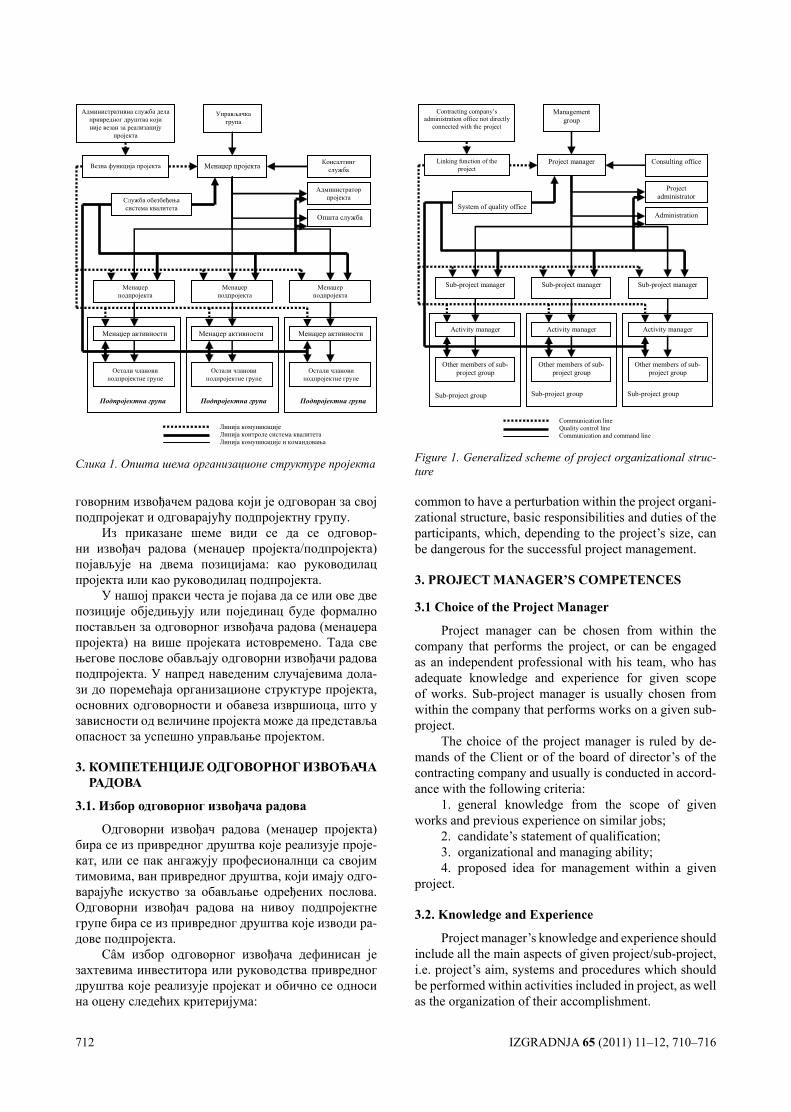
712 IZGRADNJA 65 (2011) 11–12, 710–716
говорним извођачем радова који је одговоран за свој подпројекат и одговарајућу подпројектну групу.
Из приказане шеме види се да се одговор-ни извођач радова (менаџер пројекта/подпројекта) појављује на двема позицијама: као руководилац пројекта или као руководилац подпројекта.
У нашој пракси честа је појава да се или ове две позиције обједињују или појединац буде формално постављен за одговорног извођача радова (менаџера пројекта) на више пројеката истовремено. Тада све његове послове обављају одговорни извођачи радова подпројекта. У напред наведеним случајевима дола-зи до поремећаја организационе структуре пројекта, основних одговорности и обавеза извршиоца, што у зависности од величине пројекта може да представља опасност за успешно управљање пројектом.
3. КОМПЕТЕНЦИЈЕ ОДГОВОРНОГ ИЗВОЂАЧА РАДОВА
3.1. Избор одговорног извођача радова
Одговорни извођач радова (менаџер пројекта) бира се из привредног друштва које реализује проје-кат, или се пак ангажују професионалнци са својим тимовима, ван привредног друштва, који имају одго-варајуће искуство за обављање одређених послова. Одговорни извођач радова на нивоу подпројектне групе бира се из привредног друштва које изводи ра-дове подпројекта.
Сâм избор одговорног извођача дефинисан је захтевима инвеститора или руководства привредног друштва које реализује пројекат и обично се односи на оцену следећих критеријума:
common to have a perturbation within the project organi-zational structure, basic responsibilities and duties of the participants, which, depending to the project’s size, can be dangerous for the successful project management.
3. PROjEcT MANAgER’S cOMPETENcES
3.1 choice of the Project Manager
Project manager can be chosen from within the company that performs the project, or can be engaged as an independent professional with his team, who has adequate knowledge and experience for given scope of works. Sub-project manager is usually chosen from within the company that performs works on a given sub-project.
The choice of the project manager is ruled by de-mands of the Client or of the board of director’s of the contracting company and usually is conducted in accord-ance with the following criteria:
1. general knowledge from the scope of given works and previous experience on similar jobs;
2. candidate’s statement of qualification;3. organizational and managing ability;4. proposed idea for management within a given
project.
3.2. Knowledge and Experience
Project manager’s knowledge and experience should include all the main aspects of given project/sub-project, i.e. project’s aim, systems and procedures which should be performed within activities included in project, as well as the organization of their accomplishment.
Административна служба делапривредног друштва којиније везан за реализацију
пројекта
Везна функција пројекта
Менаџер активности Менаџер активностиМенаџер активности
Менаџер пројекта
Општа служба
Линија комуникације Линија контроле система квалитета Линија комуникације и командовања
Подпројектна група Подпројектна група Подпројектна група
Служба обезбеђењасистема квалитета
Управљачкагрупа
Консалтингслужба
Администраторпројекта
Менаџерподпројекта
Менаџерподпројекта
Менаџерподпројекта
Остали члановиподпројектне групе
Остали члановиподпројектне групе
Остали члановиподпројектне групе
Слика 1. Општа шема организационе структуре пројекта
Project administrator
Contracting company’s administration office not directly
connected with the project
Management group
Sub-project manager
Linking function of the project
Activity manager
Other members of sub-project group
Project manager
Sub-project manager
Activity manager
Other members of sub-project group
Sub-project manager
Activity manager
Other members of sub-project group
System of quality office Administration
Consulting office
Communication line Quality control line Communication and command line
Sub-project group
Sub-project group
Sub-project group
Figure 1. Generalized scheme of project organizational struc-ture
IZGRADNJA 65 (2011) 11–12, 710–716 713
1. укупно знање и искуство у извођењу пред-метних радова и управљању сличним пројектима,
2. референце кандидата,3. организационе и управљачке способности,4. цена услуга и начини плаћања, 5. предлог концепта управљања пројектом.
3.2. Потребно знање и искуство
Знање и искуство одговорног извођача радова треба да покривају све главне аспекте пројекта/под-пројекта, односно предмет пројекта, системе и про-цедуре које се извршавају кроз активности на пројек-ту, као и организацију реализације пројекта.
Најважнији аспекти организације при реализа-цији инвестиционог пројекта од стране одговорног извођача радова посебно се тичу људи и то са аспекта процене људских особина. Процене је могуће оства-рити путем адекватне комуникације, мотивисањем организационог кадра као и доделом одговарајућих активности стручним људима [8,9].
Техничка компетентност одговорног извођа-ча радова може бити описана кроз његово знање и искуство у процесу или делу процеса реализације пројекта, а нарочито кроз активности и радне кораке и њихове узајамне зависности, кроз радне методе и подршке које ће се користити, као и кроз радне сад-ржаје и дефинисане активности.
Одговорни извођач радова у начелу би могао да задовољавајуће изведе пројекат са мало или нимало знања и искуства у процесу уређења пројекта или не-ких његових делова. Задатак одговорног извођача ра-дова у том случају био би много тежи, пошто би ко-муникација са људима ангажованим на реализацији пројекта додатно била оптерећена њиховим виђењем њега као „администратора“. То би могло довести до нерешивих ситуација које не би био у могућности да открије или предвиди довољно рано да би припремио превентивне кораке.
Са друге стране, ако одговорни извођач радова има исувише детаљно знање о процесу или деловима процеса реализације пројекта, може се десити да се „угуши” у техничким детаљима пројекта или да ису-више времена проводи у активностима за које је лич-но заинтересован. Ово је у потпуној супротности са описом његовог посла, који се огледа у извршавању задатака путем организовања других људи.
Радно искуство није увек показатељ квалитета извршеног посла одговорног извођача радова. Опште је познато да одговорни извођач радова са великим искуством, без обзира на знање, не прави почетничке грешке, међутим и поред свега тога неретко се деша-ва да му управо то искуство буде ограничавајући фак-тор. Одговорни извођач радова са радним искуством стеченим применом старих технологија или у друга-чијим управљачко-организационим условима тешко ће прихватати нове технологије и унапређење знања, што ће га онемогућити да успешно управља пројекти-ма на којима се примењују савремена достигнућа.
The main organizational aspect of the project man-ager’s job in any given project greatly concerns human resources, especially in the area of character evaluation. This kind of assessment can be achieved by the means of adequate communication, motivation of the organ-izing staff, as well as proper appointment of the duties to the right professionals [8,9].
Project manager’s technical competence can be described through his knowledge and experience in a certain process or part of a process within a project, es-pecially through activities and working steps and their interdependences, through working methods and sup-port that will be used, as well as through other proc-esses and pre-defined activities.
Generally speaking, project manager should be able to accomplish his work with a little or even with-out any knowledge or experience in such a task, but in that case his work would be much more difficult be-cause of the fact that communication wirh other par-ticipants would be influenced by their attitude towards him as an ‘administrator’. That might even lead to the undecipherable situations which he was not able to pre-dict or foresee in time in order to prepare preventive measures.
On the other hand, if project manager is ‘over-qual-ified’ (has too detailed knowledge on working process or its part), it is possible that he would get ‘suffocated’ in technical details or to spend too much time in activi-ties which are from his scope of expertise. That would be in total contradiction with his job description, which is supposed to be achieving the aim of project by the means of organizing other participants in their work.
Working experience is not necessarily illustrative for the quality of work performed by the project man-ager. It is well-know that broadly experienced project manager, regardless his knowledge, rarely makes be-ginner mistakes, but it is not uncommon that this very experience proves to be limiting factor. Project man-ager who has wide working experience gathered during the work with old technologies or in different manag-ing or working conditions would not be ready to ac-cept new technologies or to improve his knowledge, which would disable him in successful management in projects that rely on new technologies.
There is plenitude of projects that demand high level of creativity, in which case the project manager’s function would be to stimulate creativity among all other participants.
3.3. Duties and Responsibilities
From the aspect of organizational and management skills, the main project manager’s activities should be seen through planning and realization of the project or sub-project with aim to achieve the goals with optimal resources’ usage. It must be emphasized the recognition of the ‘alert signals’ and potential future problems in the early phases of the project would open possibili-ties for making adequate preventive steps. In order to
714 IZGRADNJA 65 (2011) 11–12, 710–716
Многи пројекти подразумевају висок ниво кре-ативних задатака и у том случају се примарна фун-кција одговорног извођача радова огледа у стимула-цији креативне моћи учесника пројекта.
3.3. Главне одговорности и активности
Са аспекта организационих и управљачких спо-собности, главне активности одговорног извођача ра-дова требало би посматрати кроз планирање и конт-ролу реализације пројекта или подпројекта са тежњом да се циљеви постигну са оптималним утрошком ре-сурса. Неопходно је нагласити да препознавање „сиг-нала за опасност“ и потенцијалних будућих проблема у раној фази пројекта отвара могућност предузимања одговарајућих превентивних корака. Да би се наведе-не активности могле реализовати, одговорни извођач радова дужан је да:
– направи општи план пројекта, као и да доста-ви детаљан план уговореног посла подређенима;
– предложи и изабере пројектни тим, тј. стручњаке са одговарајућим способностима (тех-ничким знањима и комуникацијским вештинама) не-опходним за реализацију пројекта;
– изводи радове према Главним пројектима на основу којих је издата грађевинска дозвола, и то у складу са прописима, стандардима, техничким нор-мативима и правилима квалитета за поједине врсте радова, инсталацију и опрему;
– организује градилиште на начин којим ће се обезбедити приступ локацији уз обезбеђење несмета-ног саобраћаја као и заштиту околине током читавог трајања реализације пројекта;
– обезбеђује сигурност објекта и лица која се налазе на градилишту као и суседних објеката и са-обраћајница;
– обезбеђује доказ о квалитету извршених радо-ва, уграђеног материјала, инсталације и опреме;
– води грађевински дневник и обезбеђује књигу инспекције, у складу са законским прописима;
– обезбеђује мерења и геодетско осматрање по-нашања тла и објекта у току извођења пројекта;
– обезбеђује објекте и околину у случају преки-да радова;
– обезбеђује законски прописану потребну гра-дилишну документацију на основу које се изводе грађевински радови;
– сазива и води састанке у вези са планирањем реализације пројекта;
– комуницира са свим учесницима пројекта из-дајући налоге, дајући савете, одговоре на питања, као и примајући информације о постигнутим резултати-ма рада, одступањима од планова пројекта, и текућим проблемима уопште;
– обезбеђује да ангажовани на реализацији про-јекта добију додатну обуку како би били способни за што ефикаснију реализацију задатака;
– ствара и одржава висок ниво мотивисаности свих учесника пројекта;
successfully accomplish all the mentioned activities, the project manager is supposed to perform following tasks:
– making the general project plan as well as in-troducing the staff to a detailed plan of the contracted project,
– proposing and choosing the projecting team, i.e. the experts with adequate abilities (technical knowl-edge and communicational skills) needed for the ac-complishment of the project,
– accomplishment of the works according to the detailed plans according to which the building licence is acquired, everything in accordance with procedures, standards, technical norms and quality demands for all the works, installations and equipment,
– building site organization that would enable ap-proach to the location without disturbing the traffic, as well as the adequate environmental measures during the entire works’ realisation;
– taking care of the security of the construction, employees at the site, neighbouring buildings and streets;
– acquisitioning the proof of quality of performed works, built-in material, installations and equipment;
– taking care of construction book (measurement book) and inspection book, all in accordance with law;
– providing proper measuring and geodetic sur-vey of soil and structure movements during the build-ing and afterwards;
– secures the building and its environment in case of temporary or permanent stopping of the works;
– acquisition of all the needed documentation as given in law, basin on which the works would be per-formed;
– calling and holding the meetings on planning the further activities;
– communication with all the participants by means of orders, advices, answering the questions, as well as collecting all the information on achieved re-sults, deviations from the project and any other current problem;
– taking care that all participants get the appropri-ate additional training in order to be more efficient in accomplishing their tasks;
– creating and maintaining high level of motiva-tion in all the participants of the project;
– direct abetting of associates’ working efficien-cy;
– initiation and supervision of proper updating of project documentation;
– accepting and admitting condition and con-sumption of the resources, as well as the content and quality of performed works;
– coordination of possible changes in technical solutions given in detailed plan, in agreement with the Designer and the Supervisor;
– proposing activities and changes that would bring the works back under control;
IZGRADNJA 65 (2011) 11–12, 710–716 715
– директно подстиче радну ефикасност сарад-ника;
– иницира и надгледа уредно ажурирање про-јектне документације;
– потврђује и одобрава стање и потрошњу ре-сурса на пројекту као и садржај и квалитет резултата рада;
– усаглашава евентуалне промене техничких решења из главног пројекта у договору са пројектан-том и надзорним органом;
– даје предлоге за активности и измене на пла-новима пројекта које ће довести пројекат поново под контолу;
– у договору са надзорним органом или надлеж-ном службом одлучује о изменама које су унутар пла-нираног временског интервала реализације пројекта;
– од надзорног органа или надлежне службе тражи одлуке о изменама које ће излазе из дефиниса-них граница пројекта;
– окончава пројекат пре времена када је то од-лучено или када су све активности предвиђене пла-ном пројекта у потпуности реализоване и резултати укупног рада прихваћени;
– извршава примопредају комплетно ажуриране докуметације стварног стања са градилишта , у јед-ном примерку, у сагласности са техничком службом за одржавање објекта у гарантном року;
– архивира сву документацију и забележи све што може бити од важности за будуће пројекте;
– сумира искуство стечено пројектом за будућу употребу.
Неопходно је нагласити да одговорни извођач радова не треба да буде „недоступан“ учесницима пројекта. Редовни састанци представљају добар на-чин одржавања контакта са другим учесницима про-јекта. Осим тога, не треба бити превише попуствљив када су у питању предлози и одлуке надређених.
Треба истаћи да су нефлексибилност и непот-ребно ометање подређених у обављању посла стал-ним контролама и прекидањима пут ка неуспешном окончању жељеног посла.
Одговорни извођач радова не треба да сâм изво-ди радне кораке, читаве активности или групе актив-ности, осим ако то није назначено у плану пројекта. У току прегледа резултата рада треба имати поверења у подређене, чиме се они додатно мотивишу за што успешнију реализацију пројекта. У случају да резул-тати неке активности нису прихватљиви, одговорни извођач не треба сâм да је понавља, него да је врати одговорном менаџеру и одговарајућим члановима подпројектне групе на поновну анализу.
4. ЗАКЉУЧАК
Неопходно је нагласити да су домаћа привредна друштва у области грађевинарства увелико орјенти-сана на пројектну организациону структуру, што зах-тева ангажовање већег броја висококвалификованих
– decisions on changes within the planned time interval of the project realisation, in agreement with the Supervisor or the adequate institution.
– asking the Supervisor or adequate institution for decisions on changes that would be out of time limita-tions given in the project;
– stopping the works before the planned ending if it is decided so or if all the planned activities have been accomplished and work results accepted;
– delivering one copy of completely finished doc-umentation on the real condition of the site in accord-ance with technical department for maintenance of the building during the maintenance period;
– archiving all the documentation and noting eve-rything that might be useful for the future projects, and
– saving the experiences for future needs.It should be emphasized that the project manager
should not be unavailable to the other participants of the project. Regular meetings are good way of main-taining contact with other members of staff. On the other hand, project manager should be not too amiable towards proposals and decisions from the higher levels of managements.
Besides abovementioned, non-flexibility and un-needed disturbing of employees during the working process by often controls and stopping would lead to the unsatisfying results.
Project manager is not supposed to perform certain working steps, the whole activities or groups of activi-ties by himself unless it is not specified in the project. During the supervision of the finished works, project manager should show that he trusts his employees, which would strongly motivate them for good work in forthcoming phases of project accomplishment. In case of unsatisfying results of some activity, project man-ager should not do repairing himself but to leave it to the responsible activity manager and his team and let them repeat work or analyses.
4. cONclUSION
It is necessary to emphasize that Serbian construc-tion companies are mostly oriented towards project or-ganizational structure, which demands engagement of larger number of highly qualified professionals who can answer demands of the modern approach to the project management.
All abovementioned and sublimed project manag-er’s duties are complex and highly organized activities that demand high level of personal knowledge, skills and experience. Accomplishment of contracted works in ac-cordance with cogent legal procedures in a manner of a ‘good professional’ is one of the imperatives in nowa-days business. Constant improvements of working proc-esses and construction technology demand of the project manager to keep on constant personal improving no mat-ter what previous professional experience he has, since it will enable him to achieve the maximal results in the future work.
716 IZGRADNJA 65 (2011) 11–12, 710–716
појединаца који могу одговорити савременом при-ступу управљања пројектима.
Напред наведене и сублимиране активности одговорног извођача радова представљају комплек-сне и високоодговорне послове који захтевају висок ниво потребних знања, вештина и искустава поједи-наца који их обављају. Извођење уговорених радо-ва у складу са конгентним правним правилима и уз поступање одговорног извођача са пажњом „доброг стручњака“, представља један од импертива у савре-меном пословању. Стално унапређење радних проце-са и технологије у градитељству изискује од одговор-ног извођача радова да се непрестано усавршава, без обзира на његово претходно стечено радно и живот-но искуство, пошто ће му то обезбедити максималне резултате у будућем раду.
ЛИТЕРАТУРА/REfERENcES
[1] Закон о планирању и изградњи (Сл. гласник РС 72/09).
Law on Planning and Construction (Official Gazette of Republic of Serbia 72/09).
[2] Крстић, Г., „Закон о планирању и изградњи“, Из-градња, 1-2(2010), 72–74
Krstić, G., „Law on Planning and Construction“, Iz-gradnja, 1-2(2010), 72–74
[3] Статут Инжењерске коморе Србије. Statute of the Serbian Chamber of Engineers
[4] 2000 Project Management Institute, A Guide to the Project Management Body of Knowledge, 2000.
[5] Project Management Tools & Techniques, Coverda-le Organization, 1999.
[6] Куриј К., Градитељски пројект менаџмент, Савез инжењера и техничара Србије, 2005.
Kurij K., Construction Project Management, Savez inženjera i tehničara Srbije, 2005.
[7] Бељаковић Д., Савремена организациона струк-тура градитељског пројекта, Међународна кон-ференција Савремени проблеми у грађевинарс-тву, Суботица, 2006.
Beljaković D., Modern Organizational Structure of a Construction Project, International Conference Modern Problems in Construction Industry, Suboti-ca, 2006.
[8] Peter Grainer, Managing Information, People and Operations, Kogan Page Limited, England, 1994.
[9] Петровић-Лазаревић, С., Вукотић, С., „Улога међународних менаџера у повећању конкурен-тности српске грађевинске делатности“, Из-градња, 9-10(2009), 401–414
Petrović-Lazarević, S., Vukotić, S., „Role of Inter-national Managers in Improving the Serbian Buil-ding Construction Industry Competitiveness “, Iz-gradnja, 9–10 (2009), 401–414.
U broju 7–8 našeg časopisa za ovu godinu, tehničkom greškom izostalo je navođenje ime-na i logoa naših DONATORA i SPONZORA. Koristimo ovu priliku da našim DONATORIMA i SPONZORIMA uputimo izvinjenje zbog ove greške i želju da nastavimo uspešnu saradnju i u narednim godinama.
Redakcija
IZGRADNJA 65 (2011) 11–12, 717–720 717
U vreme postojanja većeg bro-ja sistema obaveštenosti i njihovih sredstava kada se pritiskom dugme-ta mogu trenutno dobiti željeni po-daci najrazličitije prirode, normalno je da se moramo upitati kakav oblik pisanja knjiga o savremenoj arhitek-turi možemo, sa raznih stajališta, očekivati. Očigledno je da nas obilje podataka odvlači od pisanja gloma-znih knjiga u više desetina tomova, karakteritičnih za vremena prošla dva stoleća. Uz ovu prednost teh-ničke prirode, smena i promenljivo-sti teza u okvirima čitavog graditelj-skog poduvata ne dozvoljavaju da se o tim posebnostima obavestimo na podroban način, bez prethodne procene njihovog uticaja na celoku-pnu situaciju – iako se neprestano uveravamo u postojanje značaj-nih ili manje značajnih ideja koje bi imale vrednsot doprinosa. Ako bi se u sveukupnosti svetskog procesa građenja ustanovila nekakva vrsta periodizacije, skoro je beznačajno njihovo isticanje ukoliko se u njima ne nađu ideje koje će se razlikova-ti od onih koje smo do tada imali o stvarima prostora. Isticanje samo ključnih teza ili osmatranje čitavog procesa na razmeđu ovih ideja daje nam više razloga za pisanje takvih priloga koji se neće baviti „sitinica-ma“ raznih, prilično kabinetskih smi-šljenih „izama“, već neposrednom i nepoštednom kritikom baš u svetlu ovih pojava.
U tom cilju prirodno je izmeni-ti mnoga gledišta o raznim vrstama izražavanja, posebno udžbenika o kojima često, po dosadašnjem iskustvu, iskazujemo sumnjičavost, naročito onih koji su namenjeni viso-koškolskim ustanovama. Misleći na ove poslednje institucije ne može se prihvatiti da ova vrsta priloga treba da bude toliko sveobuhvatna kako bi se jednom knjigom ovladalo zna-njem i umenjem jedne struke, pa čak
ISTRAŽIVANJA PROSTORA U KNJIZI RANKA RADOVIĆA
POGLEDI I MIŠLJENJA
i jednog njenog dela. Tako očekuje-mo da se u ovoj oblasti prihvati te-za da ovaj prilog valja da prezentira niz ideja na kojima se svaki korisnik obaveštava i oprema za dalje studije i interesovanja, dakle mnogih drugih knjiga koje na sličan način obarđuju sva naznačena pitanja u ovoj osnov-noj knjizi.
Imajući u vidu dugogodišnje iskustvo u pojavi priloga koji obra-đuju probleme moderne arhitekture, dobro je podsetiti se da svi najzna-čajniji teoretičari i nosioci zavidnih titula priznatih graditelja, bez obzira da li se bave istorijom kao J. Joedic-ke, S. Giedion, B. Zevi i drugi ili se držeći se samo jedne epohe – svi oni imaju kao osnovni motiv svojih iskaza određenu ideju kojom objaš-njavaju i kojoj podređuju svoje sta-vove.
Dve knjige o modernoj arhitek-turi – Ranko Radović: „Savremena arhitektura“ (između stalnosti i pro-mena ideja i oblika) i Miloš Perović: „Istorija moderne arhitekture“ (antologija tekstova) nisu primljene prema njihovom stvarnom značenju jer je sigurno da se ovakve knjige ne pojavljuju svakog dana i naša sredina, osim manjih studija i poje-dinačnih priloga, nije do sada imala ovakav paralelan izbor, tako da pravi izazov za struku može biti samo na-stojanje da ovakve knjige proprate polemikama o vrednosti ideja koje su u njima izložene a ne o načinu kako su to autori učinili. Činjenica je, takođe da se ovakvi prilozi, po svojoj obuhvatnosti, ređe nalaze i u onim zemljama gde se u toku godine izda nekoliko stotina naslova o arhitektu-ri, pa je i to razlog da ovo primimo sa malo više dobre volje. Da li je to smelost jednog autora da nam pre-zentuje druge autore sa tekstovima, ili, pak drugog da uz jedan zanimljiv podnaslov – arhitektura između stal-nosti i promena ideja i oblika – doda
uz mnoga tuđa i svoja razmišljanja – nema spora. Obe knjige su pod-sticajne: Perovićeva, sa teoretskim tekstovima prošlih epoha, odabranim kriterijumom autora – kao završene misli i zaključci što možemo prihva-titi ili o njima diskutovati ali koje nas neosporno obaveštavaju o duhu vre-mena iz kojih potiču i time otkrivaju ne samo pojedinačne stavove nego i programska načela čitavih škola. Tako Perovićeva antologija pred-stavlja dopunu naših znanja o idej-nim kretanjima arhitektonske misli a što nam je više bilo dostupno kao rezultat izgrađene sredine dok se o idejama njihovih stvaralaca znalo vi-še uopšteno, kao globalnoj odrednici dotičnih vremena. Skorašnji odlazak drugog autora i za nas gubitak vr-snog poznavaoca savremenih arhi-tektonskih zbivanja i misli postavio je u središte naše pažnje poslednje obimno delo Ranka Radovića – knji-gu „Savremena arhitektura“.
* * *
Knjiga Ranka Radovića pisana u duhu opozitnosti događaja i akci-ja tragajući za idejama u njihovom kolebljivom životu istakla je sve ono što se danas postavlja kao pitanje o čuvenoj hamletovskoj dilemi arhitek-ture i istorije, evolucije i kontinuiteta, sve u okvirima društvenih i individu-alnih zbivanja.
Dok u prvom delu obrađuje po-stojanost promene u modernoj arhi-tekturi kao koncept, u drugom je ori-jentisan na stalnost i promene ideja, a u poslednjem, trećem delu, pod naslovom „Stalnosti promene oblika“ – čime je ovaj veliki finale, carstvo forme, u sedam poglavlja iscrplju-je najprobirljivije interesovanje jer „svakoj misli pripada njen oblik“ po rečima Rože Kajoa, a što nam Ran-ko Radović u potpunosti i dokazuje. Uverivši nas u uzajamnost uticaja
718 IZGRADNJA 65 (2011) 11–12, 717–720
– ideja i oblika – stalnosti i promene – osnažio je naša promišljanja kao moguće akcije u polju tog neiscr-pnog trezora (da se podsetimo opet pisca Estetskog rečnika Rože Kajoa: „Umetnost se često sastoji u istovre-menom ovladavanju suprotnih za-povesti“). Ako se arhitektura u bilo čemu približava umetnostima onda je to svakako u ovom iskazu Rože Kajoa koji je odbranjen i dokazan knjigom Ranka Radovića.
Da bi se stvarnost oblika prika-zala u svojoj sveobuhvatnosti bilo je potrebno ukazati na sva vredna mišljenja koja su često suprotna. Istovremeno, ako se shvati pravi tok evolucije ideja, u kojima uvek ti-nja njihova suprotnost kao predigra promenama, odnosno rađanje novih ideja – sve te osobenosti oblika ne-moguće je prikazati, a da se u su-protstavljanju mišljenja ne ukaže na tzv. srednji put – put dovoljno oba-zriv da se ne zalaže za ekstremno predložene ciljeve, koji se najčešće tako i završavaju, već na one druge kojima ostaje mnogo mogućnosti za različito razvijanje ideja, a protiv svakog konačno završenog oblika bez organskog utemeljenja u sredini opstanka.
Kompleksnost odnosa stalnosti i promena oblika u arhitekturi zahva-ta, pre svega, arhitekturu, a potom i sile koje na nju utiču od društvene stvarnosti, ideoloških i teoretskih su-čeljavanja, do pojedinačnih tumače-nja u struci i izvan nje. Stoga, samo ukazati na ove pojave stalnosti evo-lucije i promene dovoljan je dokaz za pohvalu, a kada to postane, po re-čima autora, istraživačka skica onda je svojevrsni podvig.
Ideja u svom postanku, obra-zovanju, nezavisna je od njene ma-terijalizacije kada su moguće i neke njene promene s obzirom na niz okolnosti koje prate njeno ostvare-nje. Pri tome ne treba gubiti iz vida da se ostvarena ideja – oblik – doživ-ljava čulima i da svako njeno simuli-ranje pa čak danas i pomoću virtuel-ne stvarnosti, nije sasvim sigurno i rezultat prvobitne ideje. Dalje, svaka pomoć nekih drugih oblasti, u ovom odnosu ideja – oblik, može samo da unese određenu zabunu u jedan komplikovan proces. Ovo se naroči-to odnosi u oslanjanju na „modrne“ discipline. Zbog raznolikosti u arhi-
tektonskim pokušajima ovoga veka, verovatno uočavajući prekomernost verbalnih objašnjenja ili njihovo ime-novanje, ni autor ne odoleva ovoj pošasti predlažući na jednom mestu, doduše uzdržano, umesto stambeni kompleksi – stambeni simpleks, ci-ljajući na negativna iskustva industri-jalizacije i slične posledice tipiziranja oblika i postupaka. Samo nabrajanje imena ovih „pravaca“ rečito nam ukazuje na ubrzanje protoka mišlje-nja i stavova u kratkom razdoblju od nekoliko decenija, što u poređenju sa minulim vekovima i promenama tokom njihove istorije, izaziva ne samo čuđenje nego i izvesnu sum-nju u opravdanost ubrzanja takvog razvoja. Ali, kako uticaj semantičkih istraživanja u književnosti nije mo-gao da mimoiđe ni ostale discipline savrmene nauke i umetnosti – kao odjek „imenovanja“ pojava i ideja, to nije moglo da zaobiđe ni arhitekturu u preuzimanju naziva od drugih dis-ciplina, ta imena često postaju svrha sama sebi, što nije promaklo pažnji autoru Savremene arhitekture.
Upoznavajući nas sa mnogim iskazima gotovo neverovatnog bro-ja ne samo savremenih autora ar-hitektonske misli, Ranko Radović je često zapitan da li bi se mogle prihvatiti sve pomenute klasifikacije ili „intelektualne spekulacije“ nudeći nam i svoje zaključke sa kojima se ne moramo uvek složiti, ali koje nas sigurno inspirišu da se i mi zamisli-mo nad uobičajenim tvrdnjama u koje smo i sami često sumnjali. Ta-ko smo već na samom početku ove obimne knjige načisto sa dva mnogo zloupotrebljavana pojma kada je reč o modernoj arhitekturi i ukorenjenim mišljenjem o opštoj istoriji arhitektu-re i njenim nacionalnim i regionalnim istorijama. Bez obzira na mnoge de-klaracije i odricanja ovih dveju kate-gorija Radović nam pokazuje da se savremena arhitektura nije mogla lišiti ni kroz teoretske stavove, a još manje postupke u građenju, ni isto-rije, ni tradicije. Raduje nas što se pisac knjige slaže sa iskazom Ch. Jencks-a da posledice ekstremnog pristupa, takvog pristupa u oba prav-ca, neće doneti istinsku radost ni ar-hitekturi ni gradovima.
Istorija-teorija i praksa arhitek-ture – su potka ili potpora kojima se dokazuje proces razmišljanja i na-
stajanja arhitekture, čitamo u knjizi Ranka Radovića. U svim polemičkim iskazima kojima ilustruje svoja zapa-žanja, pisac zauzima jedan „srednji“, umereni stav zrelog, obaveštenog poznavaoca koji neprekidno, kroz ceo tekst, dokazuje shvatanje o neminovnosti promene koja sama po sebi onemogućava ograničenja i uspostavljanje dogmatičnih stavo-va. Raspravljajući o ideji i principi-ma kao njenom izvorištu ili obrnuto, autor je pružio najširi mogući izbor mišljenja, pokazujući istovremeno i njihovu parcijalnost u proceni jednog totaliteta kao što je arhitektura. U na-šem vremenu brzih opštih promena ovakva razmišljanja mogu da pomo-gnu u razmatranju kolebanja između starog i novog u bilo kojoj oblasti arhitkture – od procene postojećeg do programa i projektovanja. Lo-še posledice krajnje polarizovanih opredeljenja ukazao nam je autor u odeljku izgrađeni prostor, iskustva i praksa – na primeru reagovanja so-vjetskih estetičara posle revolucije i kontroverznih rezultata proizašlih iz takvih shvatanja.
Analizovanjem promena i stal-nosti ideja kao pojavom novih misli i tumačenja, zaključuje se da su u prvom trenutku one pozitivne i da aktivaraju mnoge sledbenike, jer su najčešće reakcija na stanja ko-jima se opterećuje prirodni razvoj i spontanost kako ljudi, tako i njihove sredine. Zato su nove ideje neretko revolucionarne i često rušilačke po postojeće stanje, a deklarativno ne-trpeljive a često opterećene u zahte-vima da bi se učinak efikasnosti što pre realizovao. Međutim, primenom i striktnim sproveđenjem ovih „novih“ pravaca, osnovna ideja počinje da gubi udarnu snagu i prenebregnuvši odnose sa odgovarajućim pojavama koji direktno ili posredno iz toga od-nosa proizilaze – služeći sebi samoj – postaje sopstevena suprotnost odnosno prepreka. To se desilo sa pojavom i razvojem funkconalizma što je kao posledicu imalo reakciju, naravno, sada ekstremnu u supro-tonom pravcu. Najlogičniji zaklju-čak pri proceni takvih stanja je da se pisac knjige postavlja na stranu bodlera koji ističe kao ključni, odnos između forme i funkcije, a što pono-vo ukazuje na potrebu poznavanja i razumevanja bar većine pojava koje
IZGRADNJA 65 (2011) 11–12, 717–720 719
nazivamo istorijom moderne arhite-kure, pre nego što se usudimo da o njoj razmišljamo. Ova vrsta spre-mnosti bila je osnovni preduslov za pojavu ove korisne knjige.
Sudbina ideja u modernoj arhi-tekturi može se oceniti tek u njihovim različitim pojavnim stanjima – one nisu lebdeći duh nad arhitektonskim prostorom – već se one samo razli-čito ispoljavaju, što je autor u svom drugom delu, poglavlju, iscrpno po-kazao i ocenio. Jasno je što je pita-nje zaokupljenosti mnogih autora u poslednja dva veka bilo pre svega pitanje šta su to elementi arhitektu-re i njihovi međusobni odnosi prema totalitetu. Svakako da različitost sta-vova zavisi i od ličnih afiniteta poje-dinih autora u kojima se često uoča-vaju mnoge podudarnosti, što autor ostavlja svakom čitaocu da u ovom kaledioskopu otkriva različitosti ličnih i specifičnih ocena. Distancirajući se od zaključaka mnogih teoretičara o prenošenju arhitektonskih pokreta iz generacije u generaciju, R. Radović ipak podseća na pojedinačne sluča-jeve poznatih graditelja i njihove du-hovne veze sa njihovim prethodnici-ma kako u teoretskom smislu, tako i nastavljanjem određenih projektant-skih ideja. Time nas ponovo suoča-va sa činjenicom mnogoznačnosti ideja i njihovih puteva u savremenoj arhitekturi poslednjeg veka.
Parafrazirajući ideju J. Chen-ks-a koji je prikazao graditeljsku sa-vremenost kao seriju diskontinualnih pokreta, ukazuje na nepodudarnost između shvatanja evolucionog razvo-ja u prirodi i procesu promena u arhi-tekturi. I mi smo prisustvovali jednoj takvoj pojavi sredinom XX veka ka-da se pod uticajem društvenih prilika oživljavaju evropske ideje dvadese-tih/tridesetih godina u pogledu orga-nizacije stana (Die Wohnung für das –Existenzminimum – Internationale Kongresse für neue Bauen-Zürucg/Stuttgart 1933), napuštanjem dotada poznate organizacije najamnog sta-na u Beogradu, često primenjivane između dva svetska rata. Tako se i sami možemo uveriti u važnost ideja kao pokretača arhitektonske misli na vrlo kompleksan način.
Ranko Radović omogućava čitaocu da prouči pojave vezane za afinitet prema eklekticizmu ko-ji, kako on navodi, postoji već dva
veka u SAD-u, a sa druge strane u totalitarnim režimima u kojima se on potvrđuje oživljavanjem klasike i na-cionalnih idioma; istina Moderna je u obračunu sa klasikom više deklara-tivna nego delatna. Ukorenjene tvrd-nje o odricanju prošlosti u modernoj arhitekturi, autor opravdano pobija, navodeći činjenicu o vidljivosti isku-stva prošlosti, kao i vrednovanju ar-hitektonskog nasleđa sredinom XX veka. S druge strane, analizirajući ne mali broj realizovanih zgrada naj-čuvenijih stvaralaca ovoga perioda, nedvosmisleno nam dokazuje nji-hovu opredeljenost ka poniranju za dubinama istorijske riznice, svesno upotrebljavajući večito važeće, pro-verene postupke.
Stalno prisutna i uvek ponovna objašnjavanja u knjizi je ideja o ko-rišćenju i funkcijama arhitektonskog prostora, ideja kojoj je autor posvetio dovoljno razložnih podataka koliko i o značaju materijala, konstrukcija i tehnike građenja, čime dopunjava već izneta načela u provom delu knjige. Priroda kao mesto-genius loci-pozornica svih zbivanja u arhi-tekturi ili kao izazov, posledica ne-odvojivosti jedne od druge, dakle, priznavanje ovog kao najvrednijeg načela prirodnih zakona, uz već uo-čene uticaje društvenih pokreta, pa „kao da smo pred mnoštom stalno-sti i promena ideja o prirodi koja istu sudbinu živi u modernom dobu“ či-me autor zaključuje ovaj deo svojih razmišljanja.
U nizu prikazanih ideja u delu stalnosti i promena oblika, autor knji-ge posebnu pažnju poklanja i simbo-lizmu u modernoj arhitekturi i prihva-tajući opredeljenja da iznad „fizičkog pristupa“ postoji i simbolički nivo. U tom previranju od koga nije oslobo-đen nijedan segment istorije arhitek-ture, oblik kao rezultat kompeksnih dejstava predstavlja stalnost i uticaje promena čime se ponovo pokazuje mnogostrukost izražavanja arhitek-tonske veštine. „Produbljeno mišlje-nje o značenju“ je ozbiljna i funda-mentalna opomena autora za punu obazrivost u ovom delu posla, da se ne bi desilo da isticanje znaka bude nad arhitekturom.
U ovako iscrpnom prikazu od-nosa ideja nije se mogla izbeći i zna-čajni, ako ne i privi stepen uticaja, a to je društveni kontekst i moderna
arhitektura u ovoj „socijalnoj umet-nosti“. Polazeći od toga da društvo u najširem smislu reči „naručuje“ svako arhitektonsko delo i da program kao izraz uočenih potreba istovremeno u sebi sadrži i sva promišljanja vreme-na, Radović u daljem tekstu nizom primera podvlači značaj i restriktivno delovanje na „samostalnost“ autor-skog dela. I tako se izgleda samo idelana palata u mestu Otriv poštara Ferdinand Ševala i njemu slične mo-že smatrati delom jednog i jedinog autora-rukotvorina nastala radom ruku i bez sredstava sa strane „vla-dajuće grupe“ ili „kreativnih admini-stratora“.
Drugi deo završava se desetim poglavljem – Pregledom ideja u mo-dernoj arhitekturi sa klasifikacijom u tri grupe: ideje opšteg karaktera, ideje prostorne organizacije i „spe-cifične ideje, koja se odnosi na neki poseban aspekt arhitekture“. Pove-zujući neka izražena nastojanja na-šeg vemena, iskazana i ovaploćena kao načela, sa prethodnim iskazima u prošlosti, a na koja često nemarom vremena ne obraćamo dovoljno pa-žnje, autor je pokazao da se istori-ja nekada „ponavlja“, bez obzira na moguće modifikacije kao direktne posledice časa njihovog nastajanja.
Ako je forma, kako to ispravno misli autor, uvek neodvojiva od siste-ma, jer je posledica radnog procesa, a već ranije smo se uverili da je u sprezi i recipročnom odnosu sa ide-jom – onda možemo smatrati drugi deo knjige, koji posmatra oblik kroz istoriju u svetlu stalnosti i promena, kao dopunu i potvrdu svega rečenog u prethodnim poglavljima knjige. Što se tiče stava autora knjige – koji je ne zaboravimo i arhitekta/graditelj – on „ne gaji iluzije o arhitektonskoj formi“ u modernoj arhitekturi i zato iako u odvojenim poglavljima govo-ri o tzv. predodređenim, otvorenim i drugim formama, stiče se utisak da je i ovog puta klasifikacija ili pode-la i ovde samo zato da bi osvetlila neke važne strukturne odnose. To će nam pisac i dokazati upoređuju-ći neke dinamične i statične oblike i njihovu upotrebu u svim vremenima, a što se tiče njihove čitljivosti, ona je posledica umeća da se prepoznaju „ideali ljudi i vremena“.
Kao dugogodišnji pedagog, Radović je uočio da smo mi u svo-
720 IZGRADNJA 65 (2011) 11–12, 717–720
joj evrocentričnosti na žalost, lišeni poznavanja ili bar nagoveštaja o to-me kako se na planeti gradilo kroz vekove. Ovo postaje sve aktuelnije u vremenu potpunog odustva odnosa čoveka i prirode ne samo u pogle-du pripitomljavanja ljudskih zahteva nego i u neposrednom „prizemljenju“ svojih staništa. O vrednostima spon-tanih oblika autor je pisao još 1974. i svojom studijom sažeo ih u pet vred-nosti na šta nas ovom svojom knji-gom ponovo podseća. Ostaje nada da će dolazeće generacije u fakultet-ske programe uvrstiti upoznavanje sa globalnom istorijom arhitekture ne samo značajnih nego i „običnih“ formi, podrazumevajući da su svi elementi celine sklopa kao i sama celina zavisni od njenog formalnog opredeljenja. Razumljivo je da će promene koje neminovno prate ra-zvoj i ovde izlučiti stalne oblike koji će se uvek nanovo integrisati u novo zbog svojih neprevaziđenih kvaliteta, kao što se to dešava i u planiranom i idejom natopljenom graditeljstvu.
Baveći se pojmom element u arhitekturi Radović prihvata od mnoštva ponuđenih tumačenja, od Fillareta-a i Palladio-a do N. Schul-tza-a i Le Corbusier-a da je element, pre svega komponenta arhitekton-skog ansambla, konkretni izražajni motiv – koji bitno dejstvuje u formi-ranju. Uočavajući razlike i sličnosti koje postoje iz različitih prostornih nivoa jedinica (elemenata) koje obu-hvata arhitektura – od sobe, kuće, grupe, celine, četvrti do grada i pej-saža – autor u delu o idejama kao i u onom o oblicima, posebnu pažnju posevećuje urbanom prostoru.
Iako smo u poglavljima koja tu-mače ideje i oblike u svetlu stalnosti i promena bili suočeni i sa ovim iz oblasti urbanizma, ipak je autor ovu temu izdvojio kako u delu o misao-nim kretanjima, tako i u onom u koji-ma se one ostvaruju kao forme, čime se ideje potvrđuju ili opovrgavaju. U sažetom tekstu od samo petnaest strana upoznajemo se sa suštinskim promišljanjima o prostoru ljudskih naselja kroz vekove, od utopijskih začetaka do današnjih pokušaja nji-hovih realizacija. Ključne reči u ovoj materiji su umetničko delo, objekat, odnosi kao i red i haos – da bi se kao jedan od zaključaka moglo shvatiti tvrđenje da su ljudska masovna sta-
ništa prostorno-vremenska obele-žavanja jedne epohe. U tom smislu predlaže se sledeća periodizacija: period od 1780. do 1890. godine sa promenama društvene stvarnosti i nagle urbanizacije, rekonstrukcije, pa sve do kolonijlanog urbanizma; naravno, uz sva razlikovanja teorije i prakse građenja. Drugi period od 1890. do 1933. godine sa serijom predloga o poboljšavanju grado-va završnim aktom u vidu Atinske povelje. Treći period u vremenu od 1933. do 1960. godine sa praksom na osnovu ideologije modernog gra-da, uz internacionalizaciju urbanog poslovanja koje je odbacilo istorijske argumente-tipizacija građevina i po-stupaka što je izazvalo opravdano nezdovoljstvo takvog nametnutog prostora. I četvrti period u vremenu od 1960. do 1990. godine sav u pre-ispitivanju tzv. modernih principa ur-banizma, povratku istorije i povratku gradu, svim znanim davno oproba-nim elementima urbanog/arhitekton-skog kao sredine.
Što se urbanističkih oblika tiče zaključak je da se ovde radi o spre-zi dvaju pojmova – dakle, forma i sistem mogu biti samo zajedno raz-matani i procenjivani.
Iz tih razloga verbalno odrica-nje od poznatih uglavnom klasičnih formi, u provoj fazi Moderne, a sada oživljenih u vreme njihovog ponovnog otkivanja opet se dokazuje kontinui-tet pojava i njihova promenljivost na bilo kom nivou arhitektonskih artiku-lacija. Sa opravdanim entuzijazmom autor govori o anonimnoj arhitekturi – narodnoj ili spontanoj, bogatoj i sa drugim poznatim nazivima, kojom su inspirisani svi oni koji su bili u stanju da u njoj prepoznaju niz kvaliteta za ostvarenje takvih ansambala – ljud-skih naselja čije su namene sadržaj-no i formalno bile zadovoljene; uz to ne treba zaboraviti da „za građenje gradova jedne epohe sredstva koja su na raspolaganju uvek su na nje-nom nivou“.
* * *
Svako ko preporučuje jednu knjigu za čitanje nikada nije oslobo-đen svojih sopstvenih afiniteta i tu-mačenja, pa inspirišući se autorovim poređenjem njegove knjige sa mu-zičkim delom može se takođe reči da je ova trodelna kompozicija poput
koncerta za solo i orkestar, gde je so-lista sam pisac čiji nas duh vodi kroz gusto tkivo arhitektonskih ideja i obli-ka kroz sva tri stava ove neobične kompozicije. U prvom i najobimnijem stavu vidimo temu „između stalnosti i promena“ sa varijacijama, pri čemu u drugom stavu o oblicima variraju tema o idejama i pojavama iz prvog stava. Odabrane i kvalitetne ilustra-cije objašnjavaju izrečeno od kojih 76 fotografija u boji pripadaju takođe stavaralačkom talentu samog pisca što njegove tvrdnje i zapažanja čini još verodostojnijim, jer je najsrećnija situacija kada se arhitektonsko delo doživi ličnim kontaktom, sopstvenim čulima i zajedničkom atmosferom koja ih okružuje. Tu privilegiju nam autor kroz svoju prizmu prezentuje i na ovaj način. Drugi deo se sasto-ji od obimnog spiska napomena i objašnjenja u dovoljnom broju i sa mnogo podataka da i sam predstav-lja knjigu za sebe. Tako se po rečima pozajmljenim od Slondela (kako tvr-di autor knjige) izbegava stalno pre-kidanje što bi ga učinilo zamornim.
U trećem delu nudi se grupa odabranih bibliografija posebno svr-stanih u kategorije što iz indeksa imena čitaocu olakšava brz uvid u izvore upotrebljenih citata. Objaš-njenja i napomene čitaju se kao zanimljivi strip prostorne avanture mnogih stvaralaca i stanja koja su se desila u toku dva veka. Mišljenja mnogih autora ovde nisu samo pot-krepila razmeđu ideja i oblika već su ovi dodatni delovi knjige nesumnjivi dokaz jednog pravnog naučno-istra-živačkog posla koji je učinio autor knjige „Savremena arhitektura“. Njeno preimućstvo je isticanje svih problema na jedan istinit način, li-šen dogmatike i zaokupljenosti lič-ne isključivosti, a što će sigurno biti korišćeno kao pedagoško štivo u budućim studijama mnogih specijali-sta i svih zainteresovanih za poslove prostora u arhitekturi.
P.S. Ovaj tekst sada je samo podsećanje na jedan vredan život i uvažavanje misli koje nam je autor nesebično nudio.
Elza MILENKOVIĆ, DIA
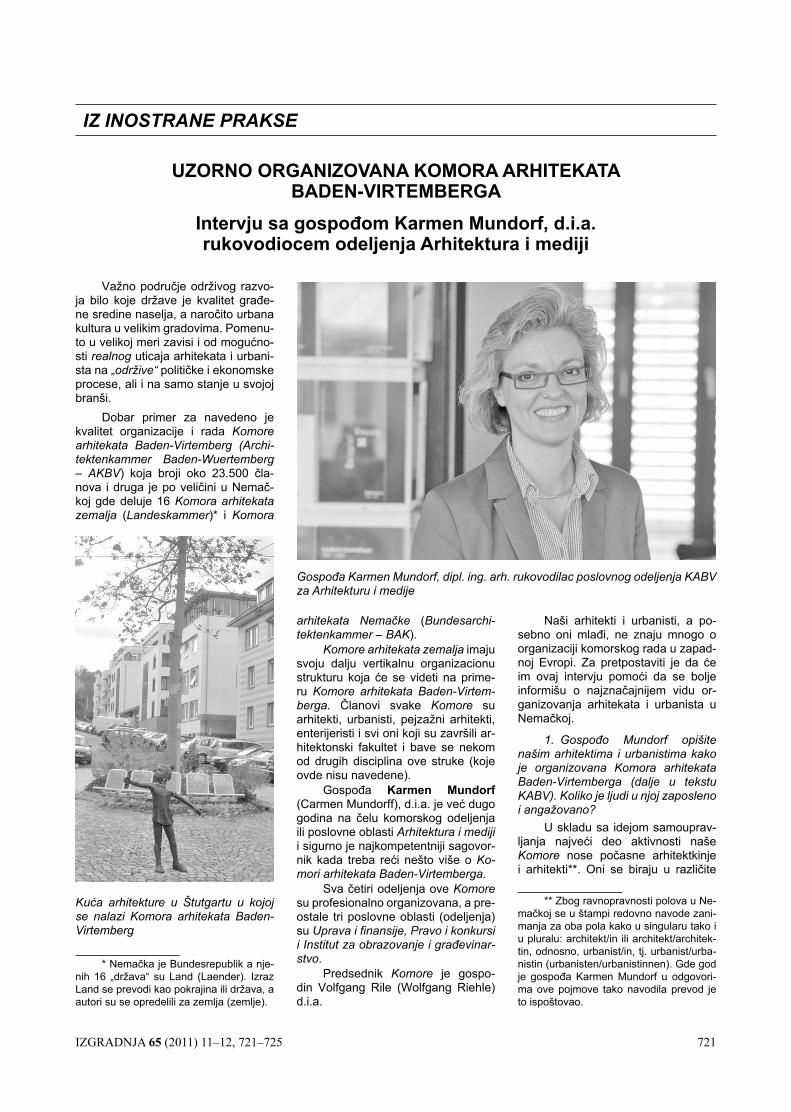
IZGRADNJA 65 (2011) 11–12, 721–725 721
Važno područje održivog razvo-ja bilo koje države je kvalitet građe-ne sredine naselja, a naročito urbana kultura u velikim gradovima. Pomenu-to u velikoj meri zavisi i od mogućno-sti realnog uticaja arhitekata i urbani-sta na „održive“ političke i ekonomske procese, ali i na samo stanje u svojoj branši.
Dobar primer za navedeno je kvalitet organizacije i rada komore arhitekata Baden-Virtemberg (Archi-tektenkammer Baden-Wuertemberg – AkBV) koja broji oko 23.500 čla-nova i druga je po veličini u Nemač-koj gde deluje 16 Komora arhitekata zemalja (Landeskammer)* i komora
UZORNO ORGANIZOVANA KOMORA ARHITEKATA BADEN-VIRTEMBERGA
Intervju sa gospođom Karmen Mundorf, d.i.a. rukovodiocem odeljenja Arhitektura i mediji
IZ INOSTRANE PRAKSE
arhitekata Nemačke (Bundesarchi-tektenkammer – BAK).
Komore arhitekata zemalja imaju svoju dalju vertikalnu organizacionu strukturu koja će se videti na prime-ru Komore arhitekata Baden-Virtem-berga. Članovi svake komore su arhitekti, urbanisti, pejzažni arhitekti, enterijeristi i svi oni koji su završili ar-hitektonski fakultet i bave se nekom od drugih disciplina ove struke (koje ovde nisu navedene).
Gospođa Karmen Mundorf (Carmen Mundorff), d.i.a. je već dugo godina na čelu komorskog odeljenja ili poslovne oblasti Arhitektura i mediji i sigurno je najkompetentniji sagovor-nik kada treba reći nešto više o ko-mori arhitekata Baden-Virtemberga.
Sva četiri odeljenja ove komore su profesionalno organizovana, a pre-ostale tri poslovne oblasti (odeljenja) su Uprava i finansije, Pravo i konkursi i Institut za obrazovanje i građevinar-stvo.
Predsednik komore je gospo-din Volfgang Rile (Wolfgang Riehle) d.i.a.
Naši arhitekti i urbanisti, a po-sebno oni mlađi, ne znaju mnogo o organizaciji komorskog rada u zapad-noj Evropi. Za pretpostaviti je da će im ovaj intervju pomoći da se bolje informišu o najznačajnijem vidu or-ganizovanja arhitekata i urbanista u Nemačkoj.
1. Gospođo Mundorf opišite našim arhitektima i urbanistima kako je organizovana Komora arhitekata Baden-Virtemberga (dalje u tekstu KABV). Koliko je ljudi u njoj zaposleno i angažovano?
U skladu sa idejom samouprav-ljanja najveći deo aktivnosti naše komore nose počasne arhitektkinje i arhitekti**. Oni se biraju u različite
Gospođa Karmen Mundorf, dipl. ing. arh. rukovodilac poslovnog odeljenja KABV za Arhitekturu i medije
Kuća arhitekture u Štutgartu u kojoj se nalazi Komora arhitekata Baden-Virtemberg
* Nemačka je Bundesrepublik a nje-nih 16 „država“ su Land (Laender). Izraz Land se prevodi kao pokrajina ili država, a autori su se opredelili za zemlja (zemlje).
** Zbog ravnopravnosti polova u Ne-mačkoj se u štampi redovno navode zani-manja za oba pola kako u singularu tako i u pluralu: architekt/in ili architekt/architek-tin, odnosno, urbanist/in, tj. urbanist/urba-nistin (urbanisten/urbanistinnen). Gde god je gospođa Karmen Mundorf u odgovori-ma ove pojmove tako navodila prevod je to ispoštovao.
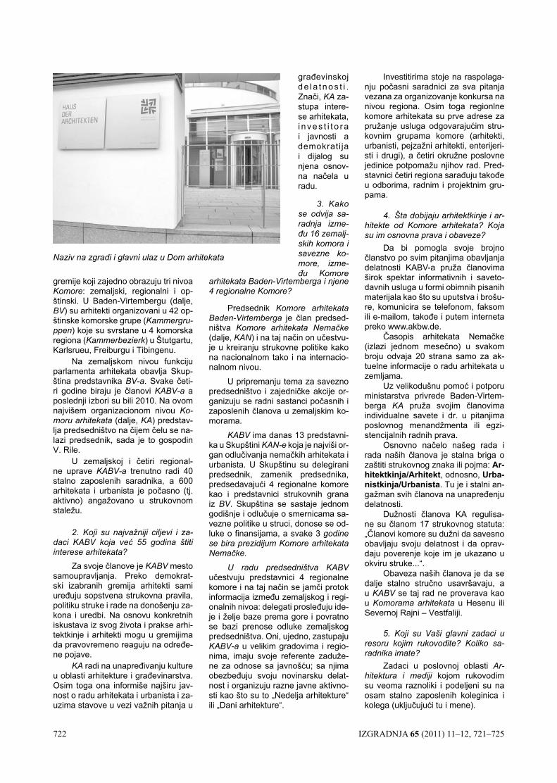
722 IZGRADNJA 65 (2011) 11–12, 721–725
gremije koji zajedno obrazuju tri nivoa komore: zemaljski, regionalni i op-štinski. U Baden-Virtembergu (dalje, BV) su arhitekti organizovani u 42 op-štinske komorske grupe (Kammergru-ppen) koje su svrstane u 4 komorska regiona (Kammerbezierk) u Štutgartu, Karlsrueu, Freiburgu i Tibingenu.
Na zemaljskom nivou funkciju parlamenta arhitekata obavlja Skup-ština predstavnika BV-a. Svake četi-ri godine biraju je članovi KABV-a a poslednji izbori su bili 2010. Na ovom najvišem organizacionom nivou ko-moru arhitekata (dalje, kA) predstav-lja predsedništvo na čijem čelu se na-lazi predsednik, sada je to gospodin V. Rile.
U zemaljskoj i četiri regional-ne uprave KABV-a trenutno radi 40 stalno zaposlenih saradnika, a 600 arhitekata i urbanista je počasno (tj. aktivno) angažovano u strukovnom staležu.
2. Koji su najvažniji ciljevi i za-daci KABV koja već 55 godina štiti interese arhitekata?
Za svoje članove je kABV mesto samoupravljanja. Preko demokrat-ski izabranih gremija arhitekti sami uređuju sopstvena strukovna pravila, politiku struke i rade na donošenju za-kona i uredbi. Na osnovu konkretnih iskustava iz svog života i prakse arhi-tektkinje i arhitekti mogu u gremijima da pravovremeno reaguju na određe-ne pojave.
kA radi na unapređivanju kulture u oblasti arhitekture i građevinarstva. Osim toga ona informiše najširu jav-nost o radu arhitekata i urbanista i za-uzima stavove u vezi važnih pitanja u
arhitekata Baden-Virtemberga i njene 4 regionalne Komore?
Predsednik Komore arhitekata Baden-Virtemberga je član predsed-ništva Komore arhitekata Nemačke (dalje, kAN) i na taj način on učestvu-je u kreiranju strukovne politike kako na nacionalnom tako i na internacio-nalnom nivou.
U pripremanju tema za savezno predsedništvo i zajedničke akcije or-ganizuju se radni sastanci počasnih i zaposlenih članova u zemaljskim ko-morama.
kABV ima danas 13 predstavni-ka u Skupštini KAN-e koja je najviši or-gan odlučivanja nemačkih arhitekata i urbanista. U Skupštinu su delegirani predsednik, zamenik predsednika, predsedavajući 4 regionalne komore kao i predstavnici strukovnih grana iz BV. Skupština se sastaje jednom godišnje i odlučuje o smernicama sa-vezne politike u struci, donose se od-luke o finansijama, a svake 3 godine se bira prezidijum Komore arhitekata Nemačke.
U radu predsedništva KABV učestvuju predstavnici 4 regionalne komore i na taj način se jamči protok informacija između zemaljskog i regi-onalnih nivoa: delegati prosleđuju ide-je i želje baze prema gore i povratno se bazi prenose odluke zemaljskog predsedništva. Oni, ujedno, zastupaju KABV-a u velikim gradovima i regio-nima, imaju svoje referente zaduže-ne za odnose sa javnošću; sa njima obezbeđuju svoju novinarsku delat-nost i organizuju razne javne aktivno-sti kao što su to „Nedelja arhitekture“ ili „Dani arhitekture“.
Investitirima stoje na raspolaga-nju počasni saradnici za sva pitanja vezana za organizovanje konkursa na nivou regiona. Osim toga regionlne komore arhitekata su prve adrese za pružanje usluga odgovarajućim stru-kovnim grupama komore (arhitekti, urbanisti, pejzažni arhitekti, enterijeri-sti i drugi), a četiri okružne poslovne jedinice potpomažu njihov rad. Pred-stavnici četiri regiona sarađuju takođe u odborima, radnim i projektnim gru-pama.
4. Šta dobijaju arhitektkinje i ar-hitekte od Komore arhitekata? Koja su im osnovna prava i obaveze?
Da bi pomogla svoje brojno članstvo po svim pitanjima obavljanja delatnosti KABV-a pruža članovima širok spektar informativnih i saveto-davnih usluga u formi obimnih pisanih materijala kao što su uputstva i brošu-re, komunicira se telefonom, faksom ili e-mailom, takođe i putem interneta preko www.akbw.de.
Časopis arhitekata Nemačke (izlazi jednom mesečno) u svakom broju odvaja 20 strana samo za ak-tuelne informacije o radu arhitekata u zemljama.
Uz velikodušnu pomoć i potporu ministarstva privrede Baden-Virtem-berga kA pruža svojim članovima individualne savete i dr. u pitanjima poslovnog menandžmenta ili egzi-stencijalnih radnih prava.
Osnovno načelo našeg rada i rada naših članova je stalna briga o zaštiti strukovnog znaka ili pojma: Ar-hitektkinja/Arhitekt, odnosno, Urba-nistkinja/Urbanista. Tu je i stalni an-gažman svih članova na unapređenju delatnosti.
Dužnosti članova KA regulisa-ne su članom 17 strukovnog statuta: „Članovi komore su dužni da savesno obavljaju svoju delatnost i da oprav-daju poverenje koje im je ukazano u okviru struke...“.
Obaveza naših članova je da se dalje stalno stručno usavršavaju, a u kABV se taj rad ne proverava kao u Komorama arhitekata u Hesenu ili Severnoj Rajni – Vestfaliji.
5. Koji su Vaši glavni zadaci u resoru kojim rukovodite? Koliko sa-radnika imate?
Zadaci u poslovnoj oblasti Ar-hitektura i mediji kojom rukovodim su veoma raznoliki i podeljeni su na osam stalno zaposlenih koleginica i kolega (uključujući tu i mene).
Naziv na zgradi i glavni ulaz u Dom arhitekata
građevinskoj d e l a t n o s t i . Znači, kA za-stupa intere-se arhitekata, i n v e s t i t o r a i javnosti a demokrati ja i dijalog su njena osnov-na načela u radu.
3. Kako se odvija sa-radnja izme-đu 16 zemalj-skih komora i savezne ko-more, izme-đu Komore
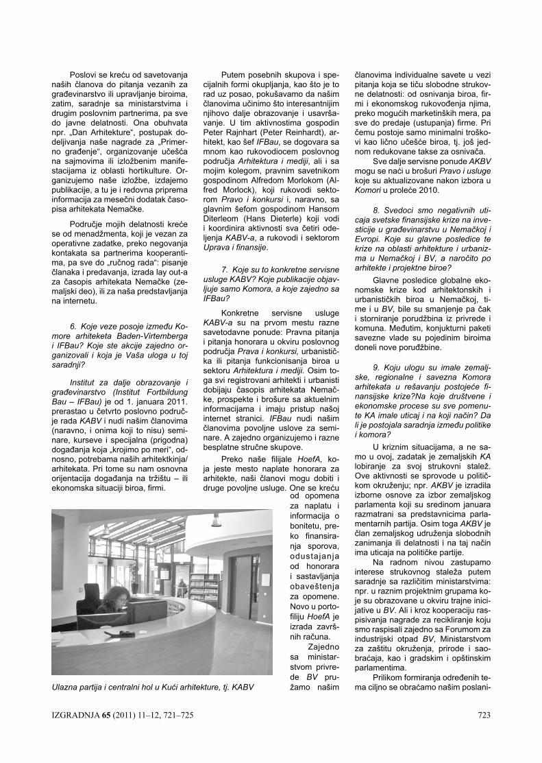
IZGRADNJA 65 (2011) 11–12, 721–725 723
Poslovi se kreću od savetovanja naših članova do pitanja vezanih za građevinarstvo ili upravljanje biroima, zatim, saradnje sa ministarstvima i drugim poslovnim partnerima, pa sve do javne delatnosti. Ona obuhvata npr. „Dan Arhitekture“, postupak do-deljivanja naše nagrade za „Primer-no građenje“, organizovanje učešća na sajmovima ili izložbenim manife-stacijama iz oblasti hortikulture. Or-ganizujemo naše izložbe, izdajemo publikacije, a tu je i redovna priprema informacija za mesečni dodatak časo-pisa arhitekata Nemačke.
Područje mojih delatnosti kreće se od menadžmenta, koji je vezan za operativne zadatke, preko negovanja kontakata sa partnerima kooperanti-ma, pa sve do „ručnog rada“: pisanje članaka i predavanja, izrada lay out-a za časopis arhitekata Nemačke (ze-maljski deo), ili za naša predstavljanja na internetu.
6. Koje veze posoje između Ko-more arhiteketa Baden-Virtemberga i IFBau? Koje ste akcije zajedno or-ganizovali i koja je Vaša uloga u toj saradnji?
Institut za dalje obrazovanje i građevinarstvo (Institut Fortbildung Bau – IFBau) je od 1. januara 2011. prerastao u četvrto poslovno područ-je rada kABV i nudi našim članovima (naravno, i onima koji to nisu) semi-nare, kurseve i specijalna (prigodna) događanja koja „krojimo po meri“, od-nosno, potrebama naših arhitektkinja/arhitekata. Pri tome su nam osnovna orijentacija događanja na tržištu – ili ekonomska situaciji biroa, firmi.
Putem posebnih skupova i spe-cijalnih formi okupljanja, kao što je to rad uz posao, pokušavamo da našim članovima učinimo što interesantnijim njihovo dalje obrazovanje i usavrša-vanje. U tim aktivnostima gospodin Peter Rajnhart (Peter Reinhardt), ar-hitekt, kao šef IFBau, se dogovara sa mnom kao rukovodiocem poslovnog područja Arhitektura i mediji, ali i sa mojim kolegom, pravnim savetnikom gospodinom Alfredom Morlokom (Al-fred Morlock), koji rukovodi sekto-rom Pravo i konkursi i, naravno, sa glavnim šefom gospodinom Hansom Diterleom (Hans Dieterle) koji vodi i koordinira aktivnosti sva četiri ode-ljenja KABV-a, a rukovodi i sektorom Uprava i finansije.
7. Koje su to konkretne servisne usluge KABV? Koje publikacije objav-ljuje samo Komora, a koje zajedno sa IFBau?
Konkretne servisne usluge KABV-a su na prvom mestu razne savetodavne ponude: Pravna pitanja i pitanja honorara u okviru poslovnog područja Prava i konkursi, urbanistič-ka ili pitanja funkcionisanja biroa u sektoru Arhitektura i mediji. Osim to-ga svi registrovani arhitekti i urbanisti dobijaju časopis arhitekata Nemač-ke, prospekte i brošure sa aktuelnim informacijama i imaju pristup našoj internet stranici. IFBau nudi našim članovima povoljne uslove za semi-nare. A zajedno organizujemo i razne besplatne stručne skupove.
Preko naše filijale HoefA, ko-ja jeste mesto naplate honorara za arhitekte, naši članovi mogu dobiti i druge povoljne usluge. One se kreću
članovima individualne savete u vezi pitanja koja se tiču slobodne strukov-ne delatnosti: od osnivanja biroa, fir-mi i ekonomskog rukovođenja njima, preko mogućih marketinških mera, pa sve do predaje (ustupanja) firme. Pri čemu postoje samo minimalni troško-vi kao lično učešće biroa, tj. još jed-nom redukovane takse za osnivača.
Sve dalje servisne ponude AkBV mogu se naći u brošuri Pravo i usluge koje su aktualizovane nakon izbora u Komori u proleće 2010.
8. Svedoci smo negativnih uti-caja svetske finansijske krize na inve-sticije u građevinarstvu u Nemačkoj i Evropi. Koje su glavne posledice te krize na oblasti arhitekture i urbaniz-ma u Nemačkoj i BV, a naročito po arhitekte i projektne biroe?
Glavne posledice globalne eko-nomske krize kod arhitektonskih i urbanističkih biroa u Nemačkoj, ti-me i u BV, bile su smanjenje pa čak i storniranje porudžbina iz privrede i komuna. Međutim, konjukturni paketi savezne vlade su pojedinim biroima doneli nove poruđžbine.
9. Koju ulogu su imale zemalj-ske, regionalne i savezna Komora arhitekata u rešavanju postojeće fi-nansijske krize?Na koje društvene i ekonomske procese su sve pomenu-te KA imale uticaj i na koji način? Da li je postojala saradnja između politike i komora?
U kriznim situacijama, a ne sa-mo u ovoj, zadatak je zemaljskih kA lobiranje za svoj strukovni stalež. Ove aktivnosti se sprovode u politič-kom okruženju; npr. AkBV je izradila izborne osnove za izbor zemaljskog parlamenta koji su sredinom januara razmatrani sa predstavnicima parla-mentarnih partija. Osim toga AkBV je član zemaljskog udruženja slobodnih zanimanja ili delatnosti i na taj način ima uticaja na političke partije.
Na radnom nivou zastupamo interese strukovnog staleža putem saradnje sa različitim ministarstvima: npr. u raznim projektnim grupama ko-je su obrazovane u okviru trajne inici-jative u BV. Ali i kroz kooperaciju ras-pisivanja nagrade za recikliranje koju smo raspisali zajedno sa Forumom za industrijski otpad BV, Ministarstvom za zaštitu okruženja, prirode i sao-braćaja, kao i gradskim i opštinskim parlamentima.
Prilikom formiranja određenih te-ma ciljno se obraćamo našim poslani-Ulazna partija i centralni hol u Kući arhitekture, tj. KABV
od opomena za naplatu i informacija o bonitetu, pre-ko finansira-nja sporova, odustajanja od honorara i sastavljanja obaveštenja za opomene. Novo u porto-filiju HoefA je izrada završ-nih računa.
Zajedno sa ministar-stvom privre-de BV pru-žamo našim
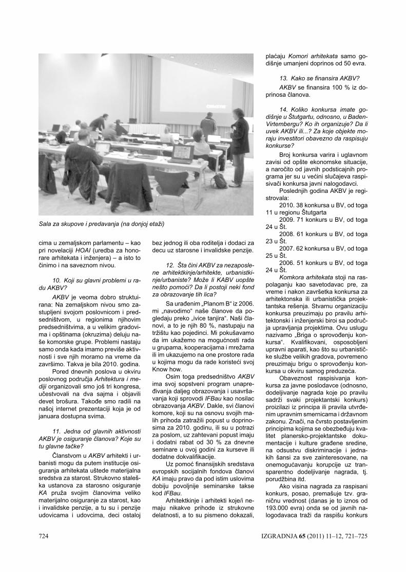
724 IZGRADNJA 65 (2011) 11–12, 721–725
cima u zemaljskom parlamentu – kao pri novelaciji HOAI (uredba za hono-rare arhitekata i inženjera) – a isto to činimo i na saveznom nivou.
10. Koji su glavni problemi u ra-du AKBV?
AkBV je veoma dobro struktui-rana: Na zemaljskom nivou smo za-stupljeni svojom poslovnicom i pred-sedništvom, u regionima njihovim predsedništvima, a u velikim gradovi-ma i opštinama (okruzima) deluju na-še komorske grupe. Problemi nastaju samo onda kada imamo previše aktiv-nosti i sve njih moramo na vreme da završimo. Takva je bila 2010. godina.
Pored dnevnih poslova u okviru poslovnog područja Arhitektura i me-diji organizovali smo još tri kongresa, učestvovali na dva sajma i objavili devet brošura. Takođe smo radili na našoj internet prezentaciji koja je od januara dostupna svima.
11. Jedna od glavnih aktivnosti AKBV je osiguranje članova? Koje su tu glavne tačke?
Članstvom u AkBV arhitekti i ur-banisti mogu da putem institucije osi-guranja arhitekata uštede materijalna sredstva za starost. Strukovno staleš-ka ustanova za starosno osiguranje kA pruža svojim članovima veliko materijalno osiguranje za starost, kao i invalidske penzije, a tu su i penzije udovicama i udovcima, deci ostaloj
bez jednog ili oba roditelja i dodaci za decu uz starosne i invalidske penzije.
12. Šta čini AKBV za nezaposle-ne arhitektkinje/arhitekte, urbanistki-nje/urbaniste? Može li KABV uopšte nešto pomoći? Da li postoji neki fond za obrazovanje tih lica?
Sa urađenim „Planom B“ iz 2006. mi „navodimo“ naše članove da po-gledaju preko „ivice tanjira“. Naši čla-novi, a to je njih 80 %, nastupaju na tržištu kao pojedinci. Mi pokušavamo da im ukažemo na mogućnosti rada u grupama, kooperacijama i mrežama ili im ukazujemo na one prostore rada u kojima mogu da rade koristeći svoj Know how.
Osim toga predsedništvo AkBV ima svoj sopstveni program unapre-đivanja daljeg obrazovanja i usavrša-vanja koji sprovodi IFBau kao nosilac obrazovanja AkBV. Dakle, svi članovi komore, koji su na osnovu svojih ma-lih prihoda zatražili popust u doprino-sima za 2010. godinu, ili su u potrazi za poslom, uz zahtevani popust imaju i dodatni rabat od 30 % za dnevne seminare u ovoj godini za kurseve ili dodatne dokvalifikacije.
Uz pomoć finansijskih sredstava evropskih socijalnih fondova članovi kA imaju pravo da pod istim uslovima dobiju povoljnije seminarske takse kod IFBau.
Arhitektkinje i arhitekti koje/i ne-maju nikakve prihode iz strukovne delatnosti, a to su pismeno dokazali,
plaćaju Komori arhitekata samo go-dišnje umanjeni doprinos od 50 evra.
13. Kako se finansira AKBV?AkBV se finansira 100 % iz do-
prinosa članova.
14. Koliko konkursa imate go-dišnje u Štutgartu, odnosno, u Baden-Virtembergu? Ko ih organizuje? Da li uvek AKBV ili...? Za koje objekte mo-raju investitori obavezno da raspisuju konkurse?
Broj konkursa varira i uglavnom zavisi od opšte ekonomske situacije, a naročito od javnih podsticajnih pro-grama jer su u većini slučajeva raspi-sivači konkursa javni nalogodavci.
Poslednjih godina AKBV je regi-strovala:
2010. 38 konkursa u BV, od toga 11 u regionu Štutgarta
2009. 71 konkurs u BV, od toga 24 u Št.
2008. 61 konkurs u BV, od toga 23 u Št.
2007. 62 konkursa u BV, od toga 25 u Št.
2006. 51 konkurs u BV, od toga 24 u Št.
Komkora arhitekata stoji na ras-polaganju kao savetodavac pre, za vreme i nakon završetka konkursa za arhitektonska ili urbanistička projek-tantska rešenja. Stvarnu organizaciju konkursa preuzimaju po pravilu arhi-tektonski i inženjerski biroi sa područ-ja upravljanja projektima. Ovu uslugu nazivamo „Briga o sprovođenju kon-kursa“. Kvalifikovani, osposobljeni upravni aparati, kao što su urbanistič-ke službe velikih gradova, povremeno preuzimaju brigu o sprovođenju kon-kursa u okviru samog preduzeća.
Obaveznost raspisivanja kon-kursa za javne poslodavce (odnosno, dodeljivanje nagrada koje po pravilu sadrži svaki projektantski konkurs) proizilazi iz principa ili pravila utvrđe-nim upravnim smernicama i državnom zakonu. Znači, na čvrsto postavljenim principima kojima se obezbeđuju kva-litet planersko-projektantske doku-mentacije i kulture građene sredine, na odsustvu diskriminacije i jedna-kih šansi za sve zainteresovane, na onemogućavanju korupcije uz tran-sparentno dodeljivanje nagrada, tj. porudžbina itd.
Ako visina nagrada za raspisani konkurs, posao, premašuje tzv. gra-ničnu vrednost (danas je to iznos od 193.000 evra) onda se od javnih na-logodavaca traži da raspišu konkurs
Sala za skupove i predavanja (na donjoj etaži)
IZGRADNJA 65 (2011) 11–12, 721–725 725
na evropskom nivou prema uredbi o dodeljivanju nagrada VOF koja je izvedena iz evropskog prava.
Investitori, kao privatna privred-na preduzeća, formalno ne podležu ovim propisima. Od strane u nekom mestu odgovornih lica (ovlaštene službe za izdavanje odobrenja, poli-tički odgovorna lica) se zahteva ras-pisivanje konkursa kao instrumenta obezbeđenja kvaliteta rešenja što je bitan preduslov za to da se uopšte omogući investiranje, tj. investicija u nekretnine.
15. AKBV, kultura građenja i ur-bana kultura – koje veze postoje iz-među AKBV i javnosti u pomenutom kontekstu?
Komora arhitekata ima zakonski zadatak, zakonsku obavezu da una-pređuje građevinsku kulturu i građe-vinarstvo, da čuva ugled strukovnog staleža, da zastupa strukovne vredno-sti i jedinstvo svog članstva. Tako se svi mi – počasno i stalno zaposleni ši-rom zemlje – uključujemo u sve teme koje su vezane za građevinsku, urba-nu kulturu i događanja u građevinar-stvu, informišemo građane o stručnim temama putem priloga u novinama, zatim na skupovima, pomoću izložbi i putem mnogih drugih aktivnosti.
16. Koju i kakvu ulogu je imala AKBV u mnogim diskusijama povo-dom novog projektas za glavnu žele-zničku stanicu u Štutgartu?
kABV je od početka planiranja, ali i u svim fazama, konstruktivno i kri-tički pratila ceo Projekt Štutgart 21– i to sa pozitivnim ishodom. Krajem no-vembra 2010. predstavnici zemaljske skupštine vodili su u Fridrihshafenu intenzivnu i u mnogim delovima kon-troverznu diskusiju o aktuelnom stavu strukovnog staleža sa ciljem da se ispita njihova dosadašnja pozicija. U kratkim crtama utvrđeno je sledeće:
– Obnovljena je spremnost arhi-tekata i urbanista Baden-Virtemberga na daljem angažovanom praćenju Projekta Štutgart 21.
– Strukovni stalež je usmeren na stručne teme: planiranje i razvoj gradova, uređenje slobodnih površina i na arhitekturu.
– Zahteva se kultura u celoku-pnom načinu rada koju odlikuju tran-sparentnost, otvorenost i razumlji-vost.
– Primeniće se jedan diferen-ciran, životni i umanjene mere struk-tuiran koncept potreban za postupan gradski razvoj Štutgarta.
– Kao osnovu za dalje predloge kABV će organizovati jedan ciklus in-formativnih skupova i diskusija u prvoj polovini 2011.
17. Vaš rad zahteva mnogo diplomatije i znanja i u njemu nema nema mesta za dnevni angažman od osam radnih sati. Opišite našim čitao-cima jedan Vaš tipičan radni dan.
Moj radni dan počinje u osam sa-ti sa pregledom i analizom štampe, a potom sledi sednica ili ugovoreni sa-stanak van kuće ili redakcijski rad po kalendaru. Kada sam u kA nalazim se sa svojim kolegama i na ručku u našem restoranu. Običnih dana napu-štam kA oko 18 časova, najčešće sa papirima u tašni koje čitam u vozu na putu ka kući. Naša uobičajena radna nedelja sastoji se iz pet takvih dana.
Često sam na sednicama kA ili u ministarstvima, prisustvujem razgo-vorima za štampu ili dodeljivanju na-grada u okviru naše dodele istih: „Pri-merno građenje“, posećujem sajmove (u januaru je to bio BAU u Minhenu) ili sarađujem u radnoj grupi Nemač-kog društva za održivu gradnju, razvoj (DGNB).
18. Vi ste veoma angažovana ličnost i svaki dan imate kontakte sa mnogim ljudima različitih zanimanja, takođe i sa medijima. Koji su glavni uspesi i problemi u Vašem radu.
Moja prednost u poslu je ta što sam kao stručnjak 15 godina radila na svim područjima arhitekture i ur-banizma. Osim toga imam iskustva u počasnom radu. Od svojih studija
volim da radim interdisciplinarno. To mi pomaže u stvaranju spona u okviru strukovnog staleža, a ponekad i prili-kom neophodnog nekomformističkog razmišljanja – kao npr. za našu aktu-elnu godišnju temu „Budućnost arhi-tekture: održivo odlučivati“.
Zanimljivo je sarađivati na ra-znolikim temama. To s vremena na vreme stvara i probleme, jer, ponekad moram reći i ne – inače se posao ne bi mogao obaviti.
19. Šta biste još želeli da kažete našim čitaocima o AKBV i o Vašem radu?
Struktura AkBV je doista za pri-mer, takođe i regionalna postavka i raznolikost zadataka. Osim toga tu je i interdisciplinarna saradnja koja obuhvata četiri osnovna poslovna po-dručja rada naše zemaljske poslovni-ce – kod nas, u AkBV, su zaposleni arhitekti, pravnici, eksperti za komuni-kacije i upravna pitanja. Dakle, nikada nije dosadno.
Da bi Vaše čitateljke i Vaši čitao-ci imali bliži uvid u naš rad preporuču-jem im posetu našem novom, već po-menutom homepage www.akbw.de.
Gospođo Mundorf zahvaljujem Vam se na interesantnim i iscrpnim odgovorima.
Kuća arhitekture u Štutgartu, u kojoj se nalazi Komora arhitekata Ba-den-Virtemberga, je moderno, čove-komerno zdanje. Uz kompletnu orga-nizaciju i izgled ovog zdanja posebno impresionira velika dvorišna terasa sa koje su pruža prelep pogled na goto-vo ceo Štutgart. Autor intervjua pre-poručuje posetu!
Intervju uradio: Dušan Prodanović
Preveli: Cvijeta Šmit i Dušan Prodanović
Fotografiju gospođe Karmen Mundorf, d. I. a. je uradio
fotograf Rene Miler (Rene Mueller), a ostale Dušan Prodanović
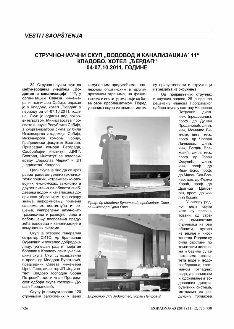
726 IZGRADNJA 65 (2011) 11–12, 726–730
32. Стручно-научни скуп са међународним учешћем „Во-довод и канализација` 11“, у организацији Савеза инжење-ра и техничара Србије, одржан је у Кладову, хотел „Ђердап“ у периоду од 04-07.10.2011. годи-не. Скуп је одржан под покро-витељством Министарства про-свете и науке Републике Србије, а суорганизатори скупа су били Инжењерска академија Србије, Инжењерска комора Србије, Грађевински факултет Београд, Привредна комора Београда, Саобраћајни институт „ЦИП“, Београд, Институт за водопри-вреду „Јарослав Черни“ и ЈП „Јединство“ Кладово.
Циљ скупа је био да се кроз разматрање актуелних техничко-технолошких, истраживачко-раз-војних, економских, законских и других питања из области снаб-девања водом и каналисања до-принесе убрзанијем трансферу знања, информисању, примени савремених достигнућа и ре-шења, унапређењу научно-ис-траживачког и развојног рада и побољшању пословања преду-зећа водовода и канализације и комуналних система.
Скуп је отворио генерални секретар СИТС, мр Бранислав Вујиновић и пожелео добродош-лицу, успешан рад и пријатан боравак у Кладову свим учесни-цима скупа. Скуп су поздравили и проф. др Миодраг Булатовић, председник Савеза инжењера Црне Горе, директор ЈП „Јединс-тво“ Кладово господин Зоран Петровић, као и члан Програм-ског одбора скупа господин Ду-шан Продановић.
Скупу је присуствовало 120 стручњака запослених у јавно
СТРУЧНО-НАУЧНИ СКУП „ВОДОВОД И КАНАЛИЗАЦИЈА` 11“ КЛАДОВО, ХОТЕЛ „ЂЕРДАП“
04-07.10.2011. ГОДИНЕ
VESTI I SAOPŠTENJA
комуналним предузећима, над-лежним општинским и другим државним огранима, на факул-тетима и институтима, који се ба-ве овом проблематиком. Поред учесника скупа из земље, истом
су присуствовали и стручњаци из земаља из окружења.
Од пријављених стручних и научних радова, 25 је прошло рецензију чланова Програмског одбора скупа у саставу Нинослав
Петровић, дипл. инж. (председник), проф. др Душан Продановић, дипл. инж, Момчило Би-кицки, дипл. инж, проф. др Часлав Лачњевац, дипл. инж, Богдан Вла-ховић, дипл. инж, проф. др Горан Секулић, дипл. инж. проф. др Иван Есих, проф. др Милан Сак-Бос-нар, доц. др Фехим Кораћ, проф. др Драгица Цамов-сак, проф. др Фи-лип Кокаљ.
У оквиру рад-ног дела скупа исти су презен-товани, од стра-не еминентних стручњака из ове области, аутора из земље и инос-танства. Радови су били сврстани по тематским целина-ма и бавили су се питањима квали-тета воде и водо-снабдевања, трет-маном отпадних вода, управљањем и одржавањем во-доводних дистри-бутивних система, методама за ре-дукцију трошкова Директор ЈКП Јединство, Зоран Петровић
Проф. др Миодраг Булатовић, председник Саве-за инжењера Црне Горе
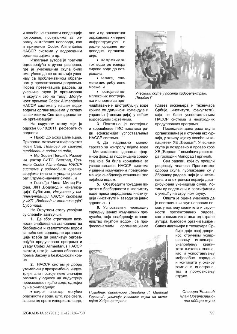
IZGRADNJA 65 (2011) 11–12, 726–730 727
и повећање тачности евиденције потрошње, поступцима за оп-равку оштећених цевовода, као и применом Codex Alimentarius HACCP система у водоводним организацијама и др.
Излагања аутора је пратила одговарајућа стручна расправа, где је учесницима скупа било омогућено да се детаљније упоз-нају са проблематиком обрађе-ном у презентованим радовима. Поред презентација радова, за учеснике скупа је организован и округли сто на тему: „Могућ-ност примене Codex Alimentarius HACCP система у нашим водо-водним организацијама у складу са захтевима Светске здравстве-не организације“.
На округлом столу који је одржан 05.10.2011. реферате су поднели:
• Проф. др Божо Далмација, Природно-математички факултет Нови Сад, Планови за сигурно снабдевање водом за пиће,
• Мр Зоран Пендић, Развој-ни центар СИТС, Београд, При-мена Codex Alimentarius HACCP система у водоводним органи-зацијама (иначе и уводни рефе-рат Стручно-научног скупа) , и
• Госпођа Чила Милиц-Ра-фаи, ЈКП „Водовод и канализа-ција“ Суботица, Искуства у им-плементацији HACCP система у ЈКП „Водовод и канализација” Суботица.
На Округлом столу усвојени су следећи закључци:
1. Да због стратешке важ-ности снабдевања становништва безбедном и квалитетном водом за пиће све водоводне организа-ције треба да реализују одгова-рајуће предусловне програме и уведу Codex Alimentarius HACCP систем, што је њихова обавеза и према Закону о безбедности хра-не.
2. HACCP систем је добро утемељен у прехрамбеној индус-трији, али постоје неке значајне разлике у односу на индустрију производње пијаће воде, од којих су најочигледније:
• широк спектар могућих опасности у води, што, пре свега, зависи од врсте изворишта воде,
чишћавање и дистрибуцију воде којима се даљински командује и управља (телеметрија) у већим водоводним системима.
3. Пожељно је постојање и коришћење ГИС података ра-ди ефикаснијег успостављања HACCP система.
4. Да надлежно минис-тарство за контролу пијаће воде – Министарство здравља, фор-мира фонд за подстицајна средс-тва која би била коришћена за успостављање HACCP система у јавним комуналним предузећи-ма која снабдевају становништво пијаћом водом.
5. Обезбедити поуздане по-датке о безбедности и квалитету воде преко меродавних институ-ција (институти и заводи за јавно здравље…)
6. Успоставити неопходну сарадњу јавних комуналних пре-дузећа, која снабдевају станов-ништво пијаћом водом, са про-фесионалним организацијама
(Савез инжењера и техничара Србије, институти, факултети), које се баве успостављањем HACCP система и неопходних предусловних програма.
Последњег дана рада скупа организована je и стручна екскур-зија, у оквиру које су посећени ка-пацитети ХЕ „Ђердап“. Учеснике скупа је поздравио и провео кроз ХЕ „Ђердап I“ помоћник директо-ра господин Милорад Гергинић.
Сви радови, који су прошли рецензију чланова Програмског одбора скупа, публиковани су у Зборнику радова, чија је и штам-пана и електронска верзија дист-рибуирана ученицима скупа. Ис-тим су подељени и сертификати о учешћу на стручном скупу.
Општа је оцена учесника да је овогодишњи скуп направио по-мак у погледу квалитета и струч-ности презентованих радова, као и самих излагања од стране аутора. Његовом организацијом, Савез инжењера и техничара Ср-
Учесници скупа у посети хидроелектрани „Ђердап I“
али и од адекватног одржавања хигијене инфраструктуре и радне средине во-доводне организа-ције;
• непрекидан ток воде од извора сирове воде до пот-рошача;
• велике, сло-жене дистрибутивне мреже, и
• постојање ко-мплексних построје-ња и опреме за пре-
Помоћник директора „Ђердапа I“, Милорад Гергинић, упознаје учеснике скупа са исто-ријом Хидроцентрале
бије даје свој допри-нос стручном усавр-шавању инжењера, унапређењу квали-тета њихових знања, као и успостављању међособне сарадње и контаката у оквиру земље и иностранс-тва и промовисању струке.
Оливера Ћосовић Члан Организацио-
ног одбора скупа

728 IZGRADNJA 65 (2011) 11–12, 726–730
VI Kongres ciglarske industri-je Srbije održan je od 21. do 23. septembra u Soko Banji u kongre-snoj dvorani hotela „Zdravljak“. Na kongresu je uzelo učešće 80 učesnika iz zemlje i 30 iz inostran-stva.Na Kongersu su bili prisutni proizvođači opreme iz Nemačke, Italije, Španije i Hrvatske, kao i proizvođači građevinskog materi-jala iz Makedonije i Bosne i Her-cegovine.
I pored veoma teških uslova privređivanja SIGP je uspeo da zahvaljujući ciglanama i crepa-nama, članicama Udruženja održi kontinuitet održavanja ovog struč-nog skupa.
Na Kongresu su razmatrane oblasti vezane za sirovinsku ba-zu, savremene tehnologije proi-zvodnje građevinskog materijala na bazi gline, primena alternativ-nih goriva u toplotnim procesima primena standarda, energetska efikasnost postrojenja, održava-nja opreme, standardizacije, za-štite životne sredine, te proizvod-nja i primena novih proizvoda i marketinga.
Na Kongresu je razmatran i predlog zakona o Rudarstvu te usvojene sugestije i primedbe na isti, koje su prosleđene resornom ministarstvu. Na kraju ovih zaklju-čaka, dajemo pismo upućeno Mi-nistarstvu.
Prestavnici inostranih firmi predstavili su nova rešenja maši-na i postrojenja sa aspekta uštede energije, kao i primenu petol kok-sa i bio mase kao alternativnog goriva.
Zbornik radova je štampan u okviru naučno-stručnog časopisa „Izgradnja“, čime će stučni ljudi iz oblasti građevinarstva pobliže in-formisani o ovoj grani građevinar-stva. U zborniku radova objavlje-no je ukupno 27 stručnih radova.
Za poseban doprinos razvoju ciglarstva Srbije dodeljene su po-volje Vladimiru Deniću, Veliboru
ZAKLJUČCI VI KONGESA CIGLARSKE INDUSTRIJE SRBIJE SA MEđUNARODNIM UČEŠĆEM
Mitroviću, Radomiru Vasiću i Sto-janu Milićeviću.
Učesnici Kongresa su doneli odluku da se časpisu „Izgradnja“ dodeli posebna zahvalnica za do-
MINISTARSTvO ZAšTITE ŽIVOTNE SREDINE INfRASTRUKTURE I RUDARSTVA SEKTOR ZA RUDARSTVO I GEOLOGIJU ZA MILICU ZORIĆPredmet: Sugestije i primedbe na Nacrt Zakona o rudarstvu i geološ-kim istraživanjima
U Soko Banji održan je VI Kon-gres ciglarske industrije Srbije, na kome je razmatran i nacrt zakona o rudarstvu i geološkim istraživanjima, te Vam ovim putem dostavljamo suge-stije i primedbe na isti:
• Član 22. Posle prvog stava treba dodati
Poslove geološkog nadzora za sopstvene potrebe kod eksploatacije sirovine za opekarsku industriju mo-že izvoditi pravno lice upisano u sud-ski registar privrednih subjekata za obavljanje te delatnosti koje ima jedno zaposleno lice sa visokom školskom spremom geološke struke odgovaraju-ćeg obrazovnog profila i ovlašćenja za obavljanje tih poslova.
• Član 46. Ko je kompetentna osoba. Treba konkretno na-vesti ko je to (autor Elabora-ta ili ko drugi)
• Član 54. Posle prvog stava dodati drugi stav
Eksploataciju sirovina za ope-karsku industriju i poslove stručnog nadzora nad izvođenjem eksploataci-je sirovine za opekarsku industriju za sopstvene potrebe može izvoditi pri-vredno društvo, odnosno drugo prav-no lice koje ima zaposleno jedno lice sa visokom školskom spremom geo-loške, rudarske ili tehnološke struke i ovlašćenja za obavljanje tih poslova .
• Član 80. Odobrenjem za izvođenje rudarskih radova nadležni organ će odrediti na osnovu složenosti površin-skog kopa opekarskih sirovi-na da li je potrebno angažo-vanje lica sa odgovarajućom stručnom spremom (ako je ležište problematično i ima potrebe za dodatnim angažo-vanjem odgovarajućih lica) tako da se član 54 može kori-govati kako stoji u predlogu
• Član 95. posle drugog stava dodati
Planovi iz stava 1. tačka 4 člana 94 ovog zakona za površinske kopo-ve opekarskih sirovina moraju se do-punjavati jednom godišnje (stanje sa 31.12.tekuće godine).
• Član 98. Posle prvog stava treba dodati stav dva
Poslove tehničkog rukovođenja pri eksploataciji opekarskih mineralnih sirovina za sopstvene potrebe može obavljati lice koje ima visoku školsku spremu geološke, rudarske i tehnološ-ke struke , tri godine radnog iskustva na odgovarajućim poslovima i ovla-šćenje za obavljanje tih poslova
• Član 99. Posle prvog stava treba dodati stav dva
Poslove stručnog nadzora pri eksploataciji opekarskih mineralnih sirovina za sopstvene potrebe može obavljati lice koje ima visoku školsku spremu geološke, rudarske i tehnološ-ke struke , tri godine radnog iskustva na odgovarajućim poslovima i ovla-šćenje za obavljanje tih poslova
U nadi da ćete uvažiti naše suge-stije i primedbe, srdačno Vas pozdrav-ljamo.
U Beogradu, 11.10.2011.god.
prinos popularizacije ciglarske in-dustrije Srbije.
Naredni VI Kongres ciglarske industrije Srbije održaće se za tri godine 2014. godine.
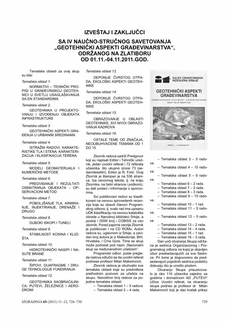
IZGRADNJA 65 (2011) 11–12, 726–730 729
Tematske oblasti za ovaj skup su bile:
Tematska oblast 1. NORMATIVI – TEHNIČKI PRO-
PISI U GRAĐEVINSKOJ GEOTEH-NICI U SVETLU USAGLAŠAVANJA SA EN STANDARDIMA
Tematska oblast 2. GEOTEHNIKA U PROJEKTO-
VANJU I IZVOĐENJU OBJEKATA INFRASTRUKTURE
Tematska oblast 3. GEOTEHNIČKI ASPEKTI GRA-
ĐENJA U URBANIM SREDINAMA
Tematska oblast 4. ISTRAŽNI RADOVI, KARAKTE-
RISTIKE TLA I STENA, KARAKTERI-ZACIJA I KLASIFIKACIJA TERENA
Tematska oblast 5. MODELI GEOMATERIJALA I
NUMERIČKE METODE
Tematska oblast 6. PREDVIĐANJE I REZULTATI
OSMATRANJA OBJEKATA – OP-SERVACIONI METOD
Tematska oblast 7. POBOLJŠANJE TLA, ARMIRA-
NJE, INJEKTIRANJE, DRENAŽE I DRUGO
Tematska oblast 8. DUBOKI ISKOPI I TUNELI
Tematska oblast 9. STABILNOST KOSINA I KLIZI-
ŠTA
Tematska oblast 10. HIDROTEHNIČKI NASIPI I NA-
SUTE BRANE
Tematska oblast 11. ŠIPOVI, DIJAFRAGME I DRU-
GE TEHNOLOGIJE FUNDIRANJA
Tematska oblast 12.
GEOTEHNIKA SAOBRAĆAJNI-CA: PUTEVI, ŽELEZNICE I AERO-DROMI
IZVEŠTAJ I ZAKLJUČCISA IV NAUČNO-STRUČNOG SAVETOVANJA
„GEOTEHNIČKI ASPEKTI GRAđEVINARSTVA“, ODRŽANOG NA ZLATIBORU OD 01.11.-04.11.2011.GOD.
Tematska oblast 13.
DEPONIJE ČVRSTOG OTPA-DA, EKOLOŠKI ASPEKTI GEOTEH-NIKE
Tematska oblast 14.
DEPONIJE ČVRSTOG OTPA-DA, EKOLOŠKI ASPEKTI GEOTEH-NIKE
Tematska oblast 15.
OBRAZOVANJE U OBLASTI GEOTEHNIKE, SVI NIVOI OBRAZO-VANJA KADROVA
Tematska oblast 16.
OSTALE TEME OD ZNAČAJA, NEOUBUHVAĆENE TEMAMA OD 1 DO 15
Zbornik radova sadrži Predgovor koji su napisali Editor i Tehnički ured-nik, jedan uvodni referat i 72 referata učesnika, što ukupno iznosi 73 (se-damdesetitri). Editor je R. Folić. Ovaj Zbornik je štampan je na 536 strani-ca. Iza osnovnog teksta, tj. na kraju Zbornika, na četiri stranice i podkorici, su dati podaci i informacije o sponzo-rima.
Svi publikovani redovi su klasifi-kovani na osnovu sprovedenih recen-zija koje su obavili članovi Program-skog odbora, tj. svaki rad ima upisanu UDK klasifikaciju na osnovu kataloške obrade u Narodnoj biblioteci Srbije, a postoji i ISSN broj i COBISS za ceo zbornik. Pored papirne verzije Zbornik je publikovan i na CD ROMu. Autori radova su, uglavnom iz Srbije, a zavi-dan broj autora je iz Makedonije, BiH, Hrvatske, i Crne Gore. Time se skup može podvesti pod naziv „Nacionalni skup sa međunarodnim učešćem“.
Programski odbor, posle pregle-da radova odlučio se da uvodni referat podnese profesor Milan Maksimović.
Zbornik radova je obuhvatio sve tematske oblasti koje su predviđene prethodnim pozivom za učešće na skupu. Navodimo broj radova za po-jedine tematske oblasti:
– Tematska oblast 1 – 5 radova– Tematska oblast 2 – 4 rada.
– Tematska oblast 3 – 5 rado-va.
– Tematska oblast 4 – 10 rado-va.
– Tematska oblast 5 – 6 rado-va.
– Tematska oblast 6 – 2 rada.– Tematska oblast 7 – 2 rada.– Tematska oblast 8 – 3 rada.– Tematska oblast 9 – 15 rado-
va.– Tematska oblast 10 – 1 rad.– Tematska oblast 11 – 5 rado-
va.– Tematska oblast 12 – 5 rado-
va– Tematska oblast 13 – 2 rada.– Tematska oblast 14 – 4 rada.– Tematska oblast 15 – 1 rad.– Tematska oblast 16 – 3 rada.Dan uoči otvaranja Skupa održa-
na je sednica Organizacionog i Pro-gramskog odbora na kojoj je obavljen izbor predsedavajućih za sve Sedni-ce. Pri tome je dogovoreno da pred-sedavajući pojedinih sednica podstiču diskusiju što je urodilo plodom.
Otvaranju Skupa prisustvova-lo je oko 110 učesnika zajedno sa gostima i domaćinom AD „PUTEVI“ Užice. Uvodni referat, na otvaranju skupa podneo je profesor dr Milan Maksimović koji je dao kratak prikaz
730 IZGRADNJA 65 (2011) 11–12, 726–730
– izveštaj o Evropskoj konferenciji nedavno održanoj u Atini i Konferen-ciji Podunavskih zemalja o geotehnici održanoj u Bratislavi. Ovaj Izveštaj je naišao na zapažen interes učesnika Skupa koji su imali neposredne kon-takte sa profesorom Maksimovićem radi detaljnijeg informisanja. Pored to-ga on je održao i predavanje naslov-ljeno: Smičuća čvrstoća krečnjačkog kamenog nabačaja koje je bilo uvod u Tematsku oblast 4.
Na otvaranju je vođena šira dis-kusija o uvođenju Evropskih normi (EN) u našu praksu, vezano za pred-stojeće aktivnosti i pristupanje Evrop-skoj uniji, jer je po nekim informacija-ma nužno što pre uvesti EN kod nas. Izraženo je jednodušno mišljenje da je u tom pravcu veoma važna uloga Inženjerske komore Srbije i Instituta za standardizaciju. Lokalna televizija je informisala javnost o Skupu i nje-govim ciljevima.
Za izlaganje Uvodnog refera-ta bilo je na raspolaganju 25 minuta i 5 minuta za diskusiju. Za izlaganje ostalih referata bilo je predviđeno 15 minuta, a za diskusiji 3 do pet minu-ta. Posle svakog izlaganja učesnici, u vremenu predviđenom za diskusiju, postavljali su pitanja i/ili davali ko-mentare i sugestije autorima i ostalim učesnicima što je uobičajena praksa na skupovima u inostranstvu, a ovog puta je prihvaćena i kod nas. Autori su se, uglavnom pridržavali planiranog vremena za izlaganje. Svim sednica-ma je bilo prisutno više od 80 učesni-ka, sem poslednjeg dana kada je taj broj bio između 30 i 40. Svi saopšteni radovi su propraćeni mnoštvom ilu-stracija na pripremljenim Power Point prezentacijama, kao i diskusijama što je napred pomenuto.
Na Savetovanju je pripremlje-no nekoliko radova sa detaljnim pri-kazom postupaka rada metodološki poznatog kao „Case Study“ što je ve-oma poučno, posebno za mlađe uče-snike. Brojni radovi odnosili su se na matematičko modeliranje u geotehni-ci uključivo različite objekte, naročito tunele i brane.
U nekim radovima istaknut je nedostatak istražnih radova, naročito geotehničkih. Kategorički je istaknu-to, da se ne sme štedeti na istražnim radovima i ispitivanjima koja se spro-vode u cilju verifikacije kvaliteta rado-va, jer to može dovesti do problema i šteta koje su višestruko veće nego ulaganja u istraživanja. Od značaja je da se nekoliko saopštenja i prezenta-
cija sponzora odnosilo na savremenu opremu za geotehnička istraživanja sa njihovim mogućnostima i ograniče-njima. U diskusiji je istaknut predlog da se uputi molba Državnim služba-ma da se kompletira i inovira oprema za laboratorijska ispitivanja saglasno odgovarajućim standardima u oblasti geotehnike, kao i opreme za terenska ispitivanja.
U jednom broju radova su pro-blemi izloženi vezano za tehničke propise. To je uslovilo i diskusije o aktuelnim problemima naše struke, Izmenama Zakona o građenju i pro-blemima uvođenja EN u našu praksu. Istaknuto je da je nužno pripremiti stručnu javnost, tj. naše inženjere za praćenje međunarodne regulative, naročito Evropskih normi (EN) koje je publikovao CEN.
U diskusijama je naglašeno je da je i pored problema koje je nametnula opšta finansijska kriza poseta ovom Savetovanju bila zadovoljavajuća, uključivo sve Sednice i prateće dis-kusije.
Na osnovu izloženog predloženi su sledeći:
ZAKLJUČCI
1. Neosporno je da našu tehničku regulativu treba usaglasiti sa Evrop-skim normama, naročito sa norma-ma EN 1997 – Eurocode 7 i EN 1998 – Eurocode 8. Međutim, ocenjeno je da bi bilo neprihvatljivo da se nave-dene evropske norme, u ovom trenut-ku, uvedu u našu građevinsku praksu jer naša struka nije pripremljena za njihovu primenu. Pored toga, tekst ovih standarda još uvek nije preveden na srpski jezik. Pošto su, u ovim stan-dardima predviđeni i članovi koji treba da odražavaju lokalne uslove koji se definišu nacionalnim parametrima, tj. potrebno je doneti Dokument sa na-cionalnim parametrima pre odluke o njihovoj primeni. Ovo se, pre svega, odnosi na faktore sigurnosti koji s ob-zirom na stanje naše laboratorijske i terenske opreme moraju da budu usklađeni sa validnošću podataka ko-je ova oprema obezbeđuje.
2. Geotehnička istraživanja, kako terenska tako i laboratorijska, treba da budu mnogo više zastuplje-na, prilikom projektovanja i izvođenja građevinskih objekata, nego što je to sada slučaj.
3. Geotehničke aspekte treba sve više uključivati pri rešavanju pro-blema zaštite životne sredine.
4. Insistiranje, odnosno aktivno učešće članova Srpskog društva za mehaniku tla i geotehničkog inže-njerstva u harmonizaciji naših propi-sa i standarda sa evropskim, koji se odnose na širu oblasti geotehnike i građevinarstva.
5. Unapređivanje i razvoj meto-doloških principa geotehničkih istra-živanja i ispitivanja, saglasno našim i svetskim normama i propisima.
6. Pokrenuti, odnosno uključiti se u definisanje neophodnog (okvir-nog) obima i vrste geotehničkih rado-va za potrebe planiranja, projektova-nja, izgradnje i eksploatacije objekata u skladu sa principima Eurocod-a 7 i drugih relevantnih tehničkih propisa, i normativa.
7. Potrebno je da članovi Druš-tva, u praksi, svesrdno podrže razvoj i unapređenje novih tehnologija u pro-jektovanju i građenju objekata, koje se pre svega, odnose na primenu no-vih (sekundarnih i otpadnih) materija-la (geotekstil, stiropor, pepeo, latex, i dr.), što je u nekim radovima prikaza-no na ovom Savetovanju.
8. Članovi Društva su iskazali po-sebno zadovoljstvo i pozdravljaju ra-zvoj i primenu savremenih monitorin-ga kod istraživanja i sanacija klizišta o objekata, naročito GNSS monitoringa i 3D laserskog skeniranja terena.
9. Na kraju opšti utisak je, da je ovo savetovanje, po naučno – struč-nom prilazu pri pisanju radova, nji-hove prezentacije i problema koje su tretirali, na nešto višem nivou od prethodnih. Posebno je zapaženo pri-sustvo većeg broja mladih stručnjaka, koji su imali aktivnu ulogu u radu Sa-vetovanja, što je za svaku pohvalu. Pošto je potvrđen značajan interes stručne javnosti za ovo Savetovanje Predloženo je da se SGIS i dalje pri-država njegovog redovnog održava-nja svake dve godine.
Komisija za zaključke:
Prof. dr Radomir Folić, dipl. građ. inž.
Prof. dr Slobodan Ćorić, dipl. građ. inž.
Mr Vladeta Vujanić, dipl. geol. inž.
Dr Nenad Šušić, dipl. građ. inž.
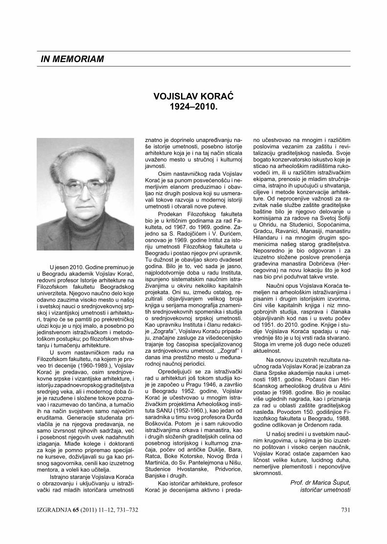
IZGRADNJA 65 (2011) 11–12, 731–732 731
U jesen 2010. Godine preminuo je u Beogradu akademik Vojislav Korać, redovni profesor Istorije arhitekture na Filozofskom fakultetu Beogradskog univerziteta. Njegovo naučno delo koje odavno zauzima visoko mesto u našoj i svetskoj nauci o srednjovekovnoj srp-skoj i vizantijskoj umetnosti i arhitektu-ri, trajno će se pamtiti po prekretničkoj ulozi koju je u njoj imalo, a posebno po jedinstvenom istraživačkom i metodo-loškom postupku; po filozofskom shva-tanju i tumačenju arhitekture.
U svom nastavničkom radu na Filozofskom fakultetu, na kojem je pro-veo tri decenije (1960-1989.), Vojislav Korać je predavao, osim srednjove-kovne srpske i vizantijske arhitekture, i istoriju zapadnoevropskog graditeljstva srednjeg veka, ali i modernog doba či-je je razuđene i složene tokove pozna-vao i razumevao do tančina, a tumačio ih na način svojstven samo najvećim eruditama. Generacije studenata pri-vlačila je na njegova predavanja, ne samo izvrsnost njihovih sadržaja, već i posebnost njegovih uvek nadahnutih izlaganja. Mlađe kolege i doktoranti za koje je pomno pripremao specijal-ne kurseve, doživljavali su ga kao pri-snog sagovornika, cenili kao izuzetnog mentora, a voleli kao učitelja.
Istrajno staranje Vojislava Koraća o obrazovanju i uključivanju u istraži-vački rad mladih istoričara umetnosti
VOJISLAV KORAĆ 1924–2010.
IN MEMORIAM
znatno je doprinelo unapređivanju na-še istorije umetnosti, posebno istorije arhitekture koja je i na taj način sticala uvaženo mesto u stručnoj i kulturnoj javnosti.
Osim nastavničkog rada Vojislav Korać je sa punom posvećenošću i ne-merljivim elanom preduzimao i obav-ljao niz drugih poslova koji su usmera-vali tokove razvoja u modernoj istoriji umetnosti i otvarali nove puteve.
Prodekan Filozofskog fakulteta bio je u kritičnim godinama za rad Fa-kulteta, od 1967. do 1969. godine. Za-jedno sa S. Radojčićem i V. Đurićem, osnovao je 1969. godine Intitut za isto-riju umetnosti Filozofskog fakulteta u Beogradu i postao njegov prvi upravnik. Tu dužnost je obavljao skoro dvadeset godina. Bilo je to, već sada je jasno, najplodotvornije doba u radu Instituta, ispunjeno sistematskim naučnim istra-živanjima u okviru nekoliko kapitalnih projekata. Oni su, između ostalog, re-zultirali objavljivanjem velikog broja knjiga u serijama monografija znameni-tih srednjovekovnih spomenika i studija o srednjovekovnoj srpskoj umetnosti. Kao upravniku Instituta i članu redakci-je ,,Zografa’’, Vojislavu Koraću pripada-ju, značajne zasluge za višedecenijsko trajanje tog časopisa specijalizovanog za srdnjovekovnu umetnost. ,,Zograf’’ i danas ima prestižno mesto u međuna-rodnoj naučnoj periodici.
Opredeljujući se za istraživački rad u arhitekturi još tokom studija ko-je je započeo u Pragu 1946, a završio u Beogradu 1952. godine, Vojislav Korać je učestvovao u mnogim istra-živačkim projektima Arheološkog insti-tuta SANU (1952-1960.), kao jedan od saradnika u timu svog profesora Đurđa Boškovića. Potom je i sam rukovodio istraživanjima crkava i manastira, kao i drugih složenih graditeljskih celina od posebnog istorijskog i kulturnog zna-čaja, počev od antičke Duklje, Bara, Ratca, Boke Kotorske, Novog Brda i Martinića, do Sv. Pantelejmona u Nišu, Studenice Hvostanske, Pridvorice, Banjske i drugih.
Kao istoričar arhitekture, profesor Korać je decenijama aktivno i preda-
no učestvovao na mnogim i različitim poslovima vezanim za zaštitu i revi-talizaciju graditeljskog nasleđa. Svoje bogato konzervatorsko iskustvo koje je sticao na arheološkim radilištima ruko-vodeći im, ili u različitim istraživačkim ekipama, prenosio je mladim stručnja-cima, istrajno ih upućujući u shvatanja, ciljeve i metode konzervacije arhitek-ture. Od neprocenjive važnosti za ra-zvitak naše službe zaštite graditeljske baštine bilo je njegovo delovanje u komisijama za radove na Svetoj Sofiji u Ohridu, na Studenici, Sopoćanima, Gradcu, Ravanici, Manasiji, manastiru Hilandaru i na mnogim drugim spo-menicima našeg starog graditeljstva. Neposredno je bio odgovoran i za izuzetno složene poslove prenošenja građevina manastira Dobrićeva (Her-cegovina) na novu lokaciju što je kod nas bio prvi poduhvat takve vrste.
Naučni opus Vojislava Koraća te-meljen na arheološkim istraživanjima i pisanim i drugim istorijskim izvorima, čini više kapitalnih knjiga i niz mno-gobrojnih studija, rasprava i članaka objavljivanih kod nas i u svetu počev od 1951. do 2010. godine. Knjige i stu-dije Vojislava Koraća spadaju u naj-vrednije što je u toj vrsti rada stvarano. Stoga im vreme još dugo neće oduzeti aktuelnost.
Na osnovu izuzetnih rezultata na-učnog rada Vojislav Korać je izabran za člana Srpske akademije nauka i umet-nosti 1981. godine. Počasni član Hri-šćanskog arheološkog društva u Atini postao je 1998. godine. Bio je nosilac više uglednih nagrada, kao i priznanja za rad u oblasti zaštite graditeljskog nasleđa. Povodom 150. godišnjice Fi-lozofskog fakulteta u Beogradu, 1988. godine odlikovan je Ordenom rada.
U našoj sredini i u svetskim nauč-nim krugovima, u kojima je bio izuzet-no poštovan i visoko cenjen naučnik, Vojislav Korać ostaće zapamćen kao ličnost velike kuture, lucidnog duha, nemerljive plemenitosti i neponovljive skromnosti.
Prof. dr Marica Šuput, istoričar umetnosti
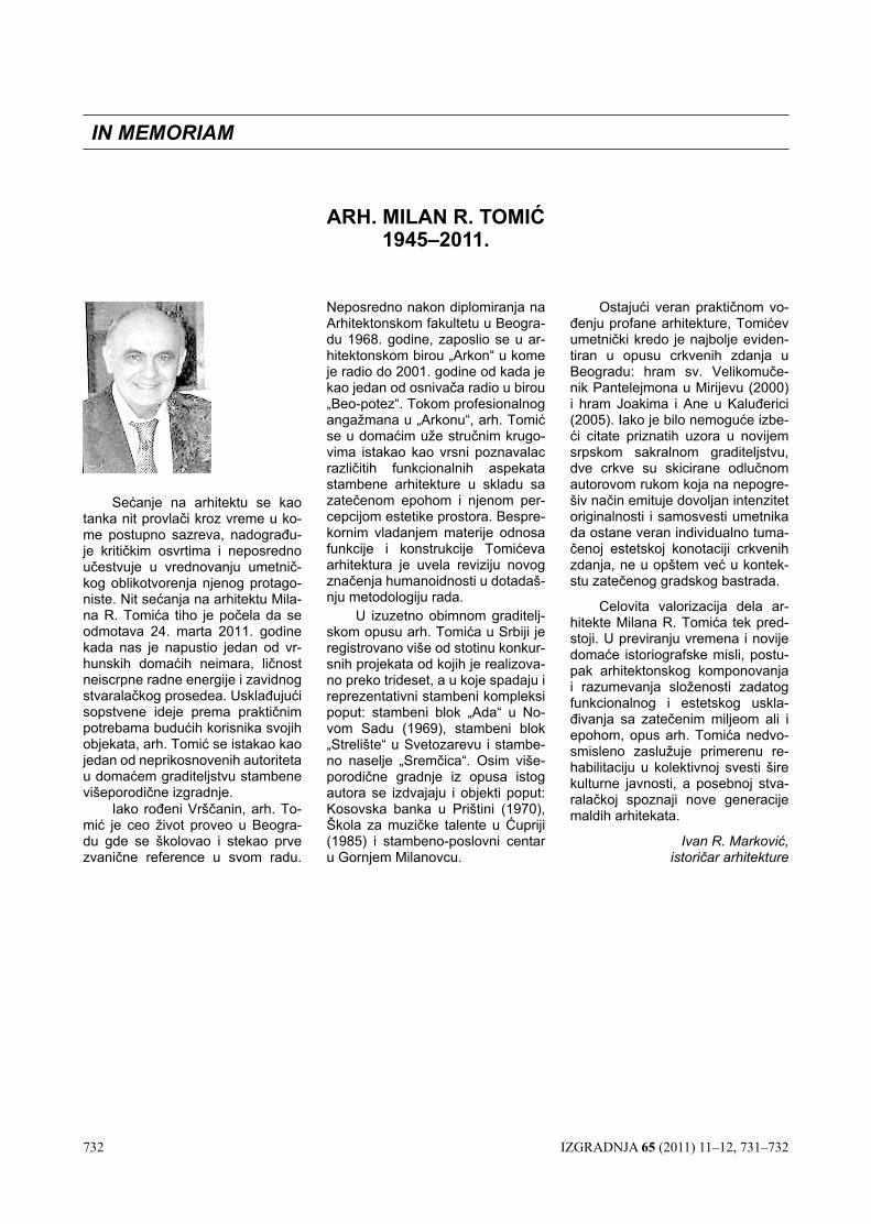
732 IZGRADNJA 65 (2011) 11–12, 731–732
Sećanje na arhitektu se kao tanka nit provlači kroz vreme u ko-me postupno sazreva, nadograđu-je kritičkim osvrtima i neposredno učestvuje u vrednovanju umetnič-kog oblikotvorenja njenog protago-niste. Nit sećanja na arhitektu Mila-na R. Tomića tiho je počela da se odmotava 24. marta 2011. godine kada nas je napustio jedan od vr-hunskih domaćih neimara, ličnost neiscrpne radne energije i zavidnog stvaralačkog prosedea. Usklađujući sopstvene ideje prema praktičnim potrebama budućih korisnika svojih objekata, arh. Tomić se istakao kao jedan od neprikosnovenih autoriteta u domaćem graditeljstvu stambene višeporodične izgradnje.
Iako rođeni Vrščanin, arh. To-mić je ceo život proveo u Beogra-du gde se školovao i stekao prve zvanične reference u svom radu.
Neposredno nakon diplomiranja na Arhitektonskom fakultetu u Beogra-du 1968. godine, zaposlio se u ar-hitektonskom birou „Arkon“ u kome je radio do 2001. godine od kada je kao jedan od osnivača radio u birou „Beo-potez“. Tokom profesionalnog angažmana u „Arkonu“, arh. Tomić se u domaćim uže stručnim krugo-vima istakao kao vrsni poznavalac različitih funkcionalnih aspekata stambene arhitekture u skladu sa zatečenom epohom i njenom per-cepcijom estetike prostora. Bespre-kornim vladanjem materije odnosa funkcije i konstrukcije Tomićeva arhitektura je uvela reviziju novog značenja humanoidnosti u dotadaš-nju metodologiju rada.
U izuzetno obimnom graditelj-skom opusu arh. Tomića u Srbiji je registrovano više od stotinu konkur-snih projekata od kojih je realizova-no preko trideset, a u koje spadaju i reprezentativni stambeni kompleksi poput: stambeni blok „Ada“ u No-vom Sadu (1969), stambeni blok „Strelište“ u Svetozarevu i stambe-no naselje „Sremčica“. Osim više-porodične gradnje iz opusa istog autora se izdvajaju i objekti poput: Kosovska banka u Prištini (1970), Škola za muzičke talente u Ćupriji (1985) i stambeno-poslovni centar u Gornjem Milanovcu.
Ostajući veran praktičnom vo-đenju profane arhitekture, Tomićev umetnički kredo je najbolje eviden-tiran u opusu crkvenih zdanja u Beogradu: hram sv. Velikomuče-nik Pantelejmona u Mirijevu (2000) i hram Joakima i Ane u Kaluđerici (2005). Iako je bilo nemoguće izbe-ći citate priznatih uzora u novijem srpskom sakralnom graditeljstvu, dve crkve su skicirane odlučnom autorovom rukom koja na nepogre-šiv način emituje dovoljan intenzitet originalnosti i samosvesti umetnika da ostane veran individualno tuma-čenoj estetskoj konotaciji crkvenih zdanja, ne u opštem već u kontek-stu zatečenog gradskog bastrada.
Celovita valorizacija dela ar-hitekte Milana R. Tomića tek pred-stoji. U previranju vremena i novije domaće istoriografske misli, postu-pak arhitektonskog komponovanja i razumevanja složenosti zadatog funkcionalnog i estetskog uskla-đivanja sa zatečenim miljeom ali i epohom, opus arh. Tomića nedvo-smisleno zaslužuje primerenu re-habilitaciju u kolektivnoj svesti šire kulturne javnosti, a posebnoj stva-ralačkoj spoznaji nove generacije maldih arhitekata.
Ivan R. Marković, istoričar arhitekture
ARH. MILAN R. TOMIĆ 1945–2011.
IN MEMORIAM


![Službeni glasnik RS [godina 4, broj 11; 23.6.1995]](https://static.fdocuments.us/doc/165x107/577d29c01a28ab4e1ea7b6d9/sluzbeni-glasnik-rs-godina-4-broj-11-2361995.jpg)


