BRACKETS AND INSULATORS - · PDF fileE4 Busbar systems BRACKETS AND INSULATORS system is for...
7
E2 Busbar systems BRACKETS AND INSULATORS system is for constructing busbar systems with rated currents up to 5000 A and rated peak short-circuit currents up to 240 kA support is made from highly sturdy fibre-reinforced thermoplastic polyester two metal connectors with M10 threading and spacing of 375 mm used to tighten supports onto busbars and anchor assembly into the structure considering their external dimensions, can be used for horizontal placement in cabinets with depths 600 mm and larger package contains: 2 supports 2 bolts 230 mm fastening materials - nuts 270 mm bolts are ordered separately Type PD-QK-DELTA110, PD-QK-DELTA210, PD-QK-DELTA310 Rated voltage 1000 V Operating temperature - 40 ÷ + 130 °C Breakdown voltage 20 kV Phase spacing 120 mm Bending strength 0,6 kN Tensile strength 20 kN Critical tensile strength 40 kN Flammability rating class UL94 - V0 Colour RAL7032 Type Product code Number of busbars in phase Code busbar dimensions Maximum busbar dimensions Weight [kg] Packing [pcs] thickness [mm] width [mm] thickness [mm] width [mm] PD-QK-DELTA110 17445 1 10 40 10 120 1.5 1 PD-QK-DELTA210 17446 2 10 40 10 120 1.45 1 PD-QK-DELTA310 17447 3 10 40 10 120 1.4 1 PD-QK-DELTA110/10 35856 1 10 40 10 120 15 10 PD-QK-DELTA210/10 35857 2 10 40 10 120 14.5 10 PD-QK-DELTA310/10 35858 3 10 40 10 120 14 10 Mounting dimensions Length/type of bolts Busbar dimensions Height of installation thickness [mm] width [mm] height [mm] 230 mm is delivered in the set of PD-QK- DELTA... 10 40 180 10 50 170 10 60 180 10 80 200 10 100 220 270 mm PD-QK-SV270 10 120 240 Specifications Type Product code Connector threading Connector length [mm] Weight [kg] Packing [pcs] PD-QK-SV270 20159 M10 270 0.16 1 BOLTS FOR BUSBAR SUPPORTS for joining and fastening DELTA busbar supports package contains: 2 connectors BUSBAR SUPPORTS
Transcript of BRACKETS AND INSULATORS - · PDF fileE4 Busbar systems BRACKETS AND INSULATORS system is for...

E2
Busbar systems
BRACKETS AND INSULATORS
system is for constructing busbar systems with rated currents up to 5000 A and rated peak short-circuit currents up to 240 kAsupport is made from highly sturdy fi bre-reinforced thermoplastic polyestertwo metal connectors with M10 threading and spacing of 375 mm used to tighten supports onto busbars and anchor assembly into the structureconsidering their external dimensions, can be used for horizontal placement in cabinets with depths 600 mm and larger
package contains:
2 supports
2 bolts 230 mm
fastening materials - nuts
270 mm bolts are ordered separately
Type PD-QK-DELTA110, PD-QK-DELTA210, PD-QK-DELTA310
Rated voltage 1000 V
Operating temperature - 40 ÷ + 130 °C
Breakdown voltage 20 kV
Phase spacing 120 mm
Bending strength 0,6 kN
Tensile strength 20 kN
Critical tensile strength 40 kN
Flammability rating class UL94 - V0
Colour RAL7032
TypeProduct
code
Number of
busbars in
phase
Code busbar
dimensions
Maximum busbar
dimensions Weight
[kg]
Packing
[pcs]thickness
[mm]
width
[mm]
thickness
[mm]
width
[mm]
PD-QK-DELTA110 17445 1 10 40 10 120 1.5 1
PD-QK-DELTA210 17446 2 10 40 10 120 1.45 1
PD-QK-DELTA310 17447 3 10 40 10 120 1.4 1
PD-QK-DELTA110/10 35856 1 10 40 10 120 15 10
PD-QK-DELTA210/10 35857 2 10 40 10 120 14.5 10
PD-QK-DELTA310/10 35858 3 10 40 10 120 14 10
Mounting dimensions
Length/type of
bolts
Busbar dimensionsHeight of
installation
thickness
[mm]
width
[mm]
height
[mm]
230 mm is
delivered in the
set of PD-QK-
DELTA...
10 40 180
10 50 170
10 60 180
10 80 200
10 100 220
270 mm
PD-QK-SV27010 120 240
Specifi cations
TypeProduct
code
Connector
threading
Connector length
[mm]
Weight
[kg]
Packing
[pcs]
PD-QK-SV270 20159 M10 270 0.16 1
BOLTS FOR BUSBAR SUPPORTSfor joining and fastening DELTA busbar supports package contains:
2 connectors
BUSBAR SUPPORTS
E3
Busbar systems
BRACKETS AND INSULATORS
Busbar dimensionsI
ks [ kA ] 10 20 30 40 50 60 70 80 90 100 110
Ikm
[ kA ] 17 40 63 84 105 132 154 176 198 220 242
width
[ mm ]
thickness
[ mm ]
number X - recommended spacing between DELTA busbar supports
of busbars [ mm ]
40 10 I 1000 800 600 500 400 300 250 230 200
40 10 II 1000 900 550 400 300 250 230 200 180
40 10 III 1000 900 600 500 400 300 250 230 200
50 10 I 1000 900 700 500 400 300 250 230 200 180 150
50 10 II 1000 900 650 500 350 300 250 230 200 180 150
50 10 III 1000 900 700 500 400 300 250 230 200 180 150
60 10 I 1000 900 700 600 400 350 300 250 200 180 150
60 10 II 1000 1000 700 500 400 350 300 250 200 180 150
60 10 III 1000 1000 850 600 500 400 350 250 200 180 150
80 10 I 1000 900 800 600 500 400 300 250 200 180 150
80 10 II 1000 1000 800 600 500 400 300 250 200 180 150
80 10 III 1000 1000 900 700 500 400 350 250 200 180 150
100 10 I 1000 1000 900 750 500 400 350 250 200 180 150
100 10 II 1000 1000 1000 800 500 400 350 250 200 180 150
100 10 III 1000 1000 1000 800 500 400 350 250 200 180 150
120 10 I 1000 1000 1000 800 500 450 350 250 200 180 150
120 10 II 1000 1000 1000 800 500 450 350 300 250 200 150
120 10 III 1000 1000 1000 900 600 500 400 300 250 200 150
Busbar dimensionsI
ks [ kA ] 10 20 30 40 50 60 70 80 90 100 110
Ikm
[ kA ] 17 40 63 84 105 132 154 176 198 220 242
width
[ mm ]
thickness
[ mm ]
number X - recommended spacing between DELTA busbar supports
of busbars [ mm ]
40 10 II 1000 1000 700 550 450 350 300 250 200
40 10 III 1000 1000 900 700 500 400 300 250 200
50 10 II 1000 1000 800 550 500 400 350 250 200 180 150
50 10 III 1000 1000 900 700 500 450 350 250 200 180 150
60 10 II 1000 1000 900 700 500 450 350 250 200 180 150
60 10 III 1000 1000 1000 800 500 450 350 250 200 180 150
80 10 II 1000 1000 1000 800 500 450 400 300 250 200 150
80 10 III 1000 1000 1000 800 500 450 400 300 250 200 150
100 10 II 1000 1000 1000 1000 800 500 400 300 250 200 150
100 10 III 1000 1000 1000 1000 800 500 400 300 250 200 150
120 10 II 1000 1000 1000 1000 800 500 400 300 250 200 150
120 10 III 1000 1000 1000 1000 800 500 400 300 250 200 150
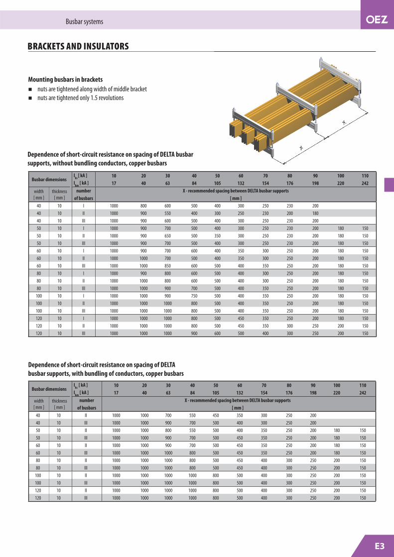
Dependence of short-circuit resistance on spacing of DELTA busbar
supports, without bundling conductors, copper busbars
Dependence of short-circuit resistance on spacing of DELTA
busbar supports, with bundling of conductors, copper busbars
Mounting busbars in brackets
nuts are tightened along width of middle bracket
nuts are tightened only 1.5 revolutions

E4
Busbar systems
BRACKETS AND INSULATORS
system is for constructing busbar systems with rated
currents up to 3700 A and rated peak short-circuit
currents up to 220 kA
support is made from highly sturdy fi bre-reinforced
thermoplastic polyester
mounting set containing two metal connectors with
M10 threading and spacers according to busbar size
used to tighten supports onto busbars and anchor
assembly into the structure
100 mm spacing of connectors for anchoring
272 mm width of rail allows use in horizontal
placement in cabinets with depth of 400 mm and
greater
package contains:
2 supports
mounting set is ordered separately
TypeProduct
code
Number of
busbars in
phase
Code busbar dimensions
thickness
Maximum busbar
dimensions Weight
[kg]
Packing
[pcs]thickness
[mm]
width
[mm]
thickness
[mm]
width
[mm]
PD-QK-DELTA110C 20752 1 10 30 10 125 1.1 1
PD-QK-DELTA210C 20753 2 10 30 10 125 1.1 1
PD-QK-DELTA305C 20754 3 5 30 5 125 1.1 1
Specifi cations
Type PD-QK-DELTA110C, PD-QK-DELTA210C, PD-QK-DELTA305C
Rated voltage 1200 V
Operating temperature - 40 ÷ + 130 °C
Rated withstand voltage 12 kV
Phase spacing 100 mm
Weight of rail group 1100 g
Capacity of group 80 kg
Tensile strength 16 kN
Critical tensile strength 22 kN
Flammability rating class UL94 - V0 kN
Tightening torque of nuts in group 15 N/m
Colour RAL7032
Busbar height
[mm]Type
Product
code
Connector
threading
Group height
[mm]
Weight
[kg]
Packing
[pcs]
30 PD-QK-DS30 20755 M10 90 0.3 1
40 PD-QK-DS40 20756 M10 100 0.3 1
50 PD-QK-DS50 20757 M10 110 0.3 1
60 PD-QK-DS60 20758 M10 120 0.3 1
80 PD-QK-DS80 20759 M10 140 0.3 1
100 PD-QK-DS100 20760 M10 160 0.3 1
120 PD-QK-DS120 20761 M10 180 0.3 1
BUSBAR SUPPORTS
for joining and fastening DELTA...C busbar supports package contains:
2 connectors
2 spacers
fastening materials
MOUNTING SETS
E5
Busbar systems
BRACKETS AND INSULATORS
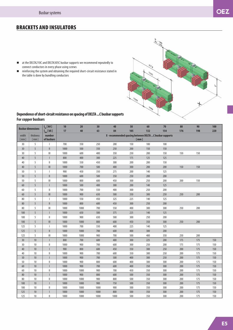
Dependence of short-circuit resistance on spacing of DELTA ...C busbar supports
For copper busbars
Busbar dimensionsI
ks [ kA ] 10 20 30 40 50 60 70 80 90 100
Ikm
[ kA ] 17 40 63 84 105 132 154 176 198 220
width
[ mm ]
thickness
[ mm ]
number
of busbars
X - recommended spacing between DELTA ...C busbar supports
[ mm ]
30 5 I 700 350 250 200 150 100 100
30 5 II 1000 500 350 250 200 150 150
30 5 III 1000 600 400 350 250 200 150 150 150
40 5 I 800 400 300 225 175 125 125
40 5 II 1000 550 450 300 200 200 150
40 5 III 1000 700 500 400 300 200 200 150 150
50 5 I 900 450 350 275 200 140 125
50 5 II 1000 600 500 350 250 200 200
50 5 III 1000 800 600 450 300 250 200 200 150
60 5 I 1000 500 400 300 200 140 125
60 5 II 1000 700 550 400 300 250 200
60 5 III 1000 900 650 500 350 300 250 250 200
80 5 I 1000 550 450 325 225 140 125
80 5 II 1000 800 600 450 300 250 200
80 5 III 1000 1000 700 550 400 300 300 250 200
100 5 I 1000 650 500 375 225 140 125
100 5 II 1000 900 650 500 300 250 200
100 5 III 1000 1000 800 600 450 350 300 250 200
125 5 I 1000 700 550 400 225 140 125
125 5 II 1000 1000 700 600 400 300 200
125 5 III 1000 1000 900 700 500 400 350 250 200
30 10 I 800 700 600 400 300 225 200 175 175 150
30 10 II 1000 900 700 600 300 250 200 175 175 150
40 10 I 900 800 600 450 350 300 250 200 175 150
40 10 II 1000 900 700 600 350 300 250 200 175 150
50 10 I 1000 900 700 500 400 300 250 200 175 150
50 10 II 1000 900 800 600 400 300 300 200 175 150
60 10 I 1000 900 700 600 400 350 300 200 175 150
60 10 II 1000 1000 900 700 450 350 300 200 175 150
80 10 I 1000 900 800 600 500 350 300 200 175 150
80 10 II 1000 1000 900 800 500 350 300 200 175 150
100 10 I 1000 1000 900 750 500 350 300 200 175 150
100 10 II 1000 1000 1000 900 500 350 300 200 175 150
125 10 I 1000 1000 1000 800 500 350 300 200 175 150
125 10 II 1000 1000 1000 1000 500 350 300 200 175 150
at the DELTA210C and DELTA305C busbar supports we recommend repeatedly to
connect conductors in every phase using screws
reinforcing the system and obtaining the required short-circuit resistance stated in
the table is done by bundling conductors

E6
Busbar systems
BRACKETS AND INSULATORS
for fastening busbars into the switchboard cabinet
busbar dimensions:
32x5 mm minimum
120x10 mm maximum
produced from glass fi bre-reinforced thermoset or
thermoplastic
M8, M10 and M12 threaded spacers
package contains:
1 support insulator
Specifi cations
Dependence of short-circuit resistance on spacing of PD-QK-PW40.. support insulators
For copper busbars
Given values valid for busbar systems with one copper busbar fl at mounted in each phase.
TypeProduct
code
Threaded
spacer
Support height
[mm]
Weight
[kg]
Packing
[pcs]
PD-QK-PW40M8 17440 M8 40 0.10 1
PD-QK-PW40M10 17441 M10 40 0.10 1
PD-QK-PW40M12 17442 M12 40 0.10 1
PD-QK-PW40M8/100 35859 M8 40 10 100
PD-QK-PW40M10/100 35860 M10 40 10 100
PD-QK-PW40M12/100 35861 M12 40 10 100
PD-QK-PIM12 17443 M12 45 0.10 1
Type PD-QK-PW40.. PD-QK-PIM12
Rated voltage 1000 V 1000 V
Operating temperature -40 ÷ +130 °C -40 ÷ +130 °C
External breakdown voltage 8 kV
Internal breakdown voltage 20 kV
Bending strength 10 kN
Tensile strength 12 kN
Torsion strength 100 N/m
Flammability rating class UL94 - V0 UL94 - V0
Y Idyn
[ kA ] 10 20 30 40 50 60 70 80 90 100
Busbar Busbar dimensions X - recommended spacing between support insulators
system width [mm]
thickness[mm] [ mm ]
6030 5-10 800 800 700 500
40 5-10 800 800 800 650 500
100
30 5-10 800 800 800 600
40 5-10 1000 1000 1000 800 700
50 5-10 1000 1000 1000 1000 800 600 550
60 5-10 1000 1000 1000 1000 800 700 550 500
80 5-10 1000 1000 1000 1000 800 600 500 480 280 250
150
30 5-10 800 800 800 750
40 5-10 1000 1000 1000 800 800
50 5-10 1000 1000 1000 1000 800 800 700
60 5-10 1000 1000 1000 1000 1000 900 800 700
80 5-10 1000 1000 1000 1000 1000 900 800 700 600 500
100 5-10 1000 1000 1000 1000 1000 900 800 700 600 500
185
30 5-10 800 800 800 800
40 5-10 1000 1000 1000 1000 900
50 5-10 1000 1000 1000 1000 1000 900 800
60 5-10 1000 1000 1000 1000 1000 1000 1000 800
80 5-10 1000 1000 1000 1000 1000 1000 1000 800 700 600
100 5-10 1000 1000 1000 1000 1000 1000 1000 800 700 600
120 5-10 1000 1000 1000 1000 1000 1000 1000 800 700 600
PD-QK-PW40M..
PD-QK-PIM12
SUPPORT INSULATORS

for QA, KB cabinetsfor mounting PD-QK-PW40M8 support insulators for horizontal mounting of PEN busbars
25 mm off set
2 mm steel sheet
galvanised fi nish
support insulator affi xed on 12.5 mm holebracket affi xed to frame on two 9x20 mm holes
package contains:
1ks holder
fastening materials
S4
Busbar systems
CONDUCTORS AND INSULATORS
RAILS FOR FIXING DELTA HOLDERS
for cabinets QA55, QA40
for the holders of main busbars DELTA, DELTA...C
for simple installation of the main busbars
asymmetric perforation of the rail for easy connection
of the main busbars
package contains:
rail fastening materials
SUPPORT INSULATOR BRACKETS
for the holder of the busbar system D100/185
or 3x(6x) supporting insulator PD-QK-PW40...
for busbar system with busbar spacing185 or 100 mm
package contains:
holder fastening materials
SUPPORT INSULATOR BRACKETS
Type Product codeWeight
[kg]
Packing
[pcs]
PD-Q13-DIM3-185 37173 0.16 1
Type Product codeOff set
[mm]
Weight
[kg]
Packing
[pcs]
PD-QK-DIVV3 37172 25 0.3 1
For cabinet
depth[mm]Type Product code
Rail height
[mm]
Weight
[kg]
Packing
[pcs]
400 PD-Q13-45LBD04 37167 45 1.5 1
500 PD-Q13-45LBD05 37168 45 2.0 1
600 PD-Q13-45LBD06 37169 45 1.0 1
800 PD-Q13-45LBD08 37170 45 1.5 1
1000 PD-Q13-45LBD10 37171 45 2.0 1
PD-Q13-DIM3-185

for QA40, QA54, and KB65 cabinetsfor mounting PD-QK-PW40M8 or PD-QK-PIM12 support
insulators for horizontal mounting of PEN busbars
30 mm off set
2 mm steel sheetgalvanised fi nishsupport insulator affi xed on 12.5 mm hole
bracket affi xed to frame on two 9x20 mm holes
package contains:
1 bracket
for QA40, QA54, KB65 cabinetsfor mounting PD-QK-PW40M8 or PD-QK-PIM12 support
insulators for horizontal mounting of PEN busbars
20 mm off set
2 mm steel sheetgalvanised fi nish support insulator affi xed on 12.5 mm hole
bracket affi xed to frame on two 9x20 mm holes
package contains:
1 bracket
for KB65 cabinetfor mounting PD-QK-PIM12 support insulators for
horizontal mounting of PEN busbars
2 mm steel sheet
galvanised fi nishsupport insulator affi xed on 12.5 mm hole
racket affi xed to frame on two 9x20 mm holes
package contains:
1 bracket
TypeProduct Weight Packing
code [kg] [pcs]
PD-QK-DIVV2 17438 0.3 1
TypeProduct Weight Packing
code [kg] [pcs]
PD-QK-DIVS 17439 0.3 1
TypeProduct Weight Packing
code [kg] [pcs]
PD-QK-DIVV1 17437 0.3 1
E7
Busbar systems
BRACKETS AND INSULATORS
SUPPORT INSULATOR BRACKETS


![StructuredGround Grounding Auxiliary Cable Brackets and ... · Grounding Busbar] (SBB/TGB) or other suitable grounding infrastructure. Cable pathway sections shall be bonded together](https://static.fdocuments.us/doc/165x107/5eb5dc8594c7ea1dad77aeb8/structuredground-grounding-auxiliary-cable-brackets-and-grounding-busbar-sbbtgb.jpg)