Fast Bus Fast Bus Busbar System - EandM · 2020-03-23 · Fast Bus Busbar Adapter System Overview...
22
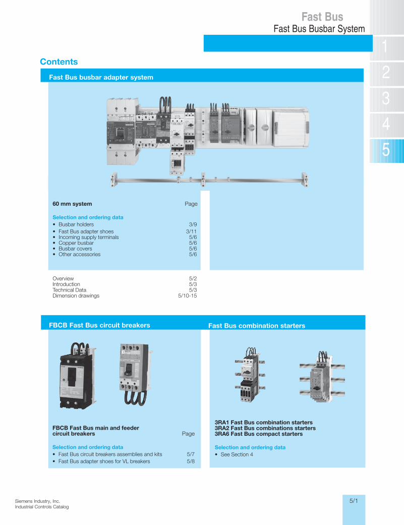
5/1 Siemens Industry, Inc. Industrial Controls Catalog Fast Bus Fast Bus Busbar System Contents FBCB Fast Bus circuit breakers Fast Bus busbar adapter system FBCB Fast Bus main and feeder circuit breakers Page Selection and ordering data • Fast Bus circuit breakers assemblies and kits 5/7 • Fast Bus adapter shoes for VL breakers 5/8 Fast Bus combination starters 3RA1 Fast Bus combination starters 3RA2 Fast Bus combinations starters 3RA6 Fast Bus compact starters Selection and ordering data • See Section 4 60 mm system Page Selection and ordering data • Busbar holders 3/9 • Fast Bus adapter shoes 3/11 • Incoming supply terminals 5/6 • Copper busbar 5/6 • Busbar covers 5/6 • Other accessories 5/6 Overview 5/2 Introduction 5/3 Technical Data 5/3 Dimension drawings 5/10-15
Transcript of Fast Bus Fast Bus Busbar System - EandM · 2020-03-23 · Fast Bus Busbar Adapter System Overview...
5/1Siemens Industry, Inc.Industrial Controls Catalog
Fast BusFast Bus Busbar System
Siemens / Industrial Controls Previous folio: 5/1
Contents
FBCB Fast Bus circuit breakers
Fast Bus busbar adapter system
FBCB Fast Bus main and feedercircuit breakers Page
Selection and ordering data• Fast Bus circuit breakers assemblies and kits 5/7• Fast Bus adapter shoes for VL breakers 5/8
Fast Bus combination starters
3RA1 Fast Bus combination starters3RA2 Fast Bus combinations starters3RA6 Fast Bus compact starters
Selection and ordering data• See Section 4
60 mm system Page
Selection and ordering data• Busbar holders 3/9• Fast Bus adapter shoes 3/11• Incoming supply terminals 5/6• Copper busbar 5/6• Busbar covers 5/6• Other accessories 5/6
Overview 5/2Introduction 5/3Technical Data 5/3Dimension drawings 5/10-15
5/2 Siemens Industry, Inc.Industrial Controls Catalog
Siemens / Industrial Controls Previous folio: 5/2
Fast BusFast Bus Busbar Adapter System
Overview
Busbar adapter systems
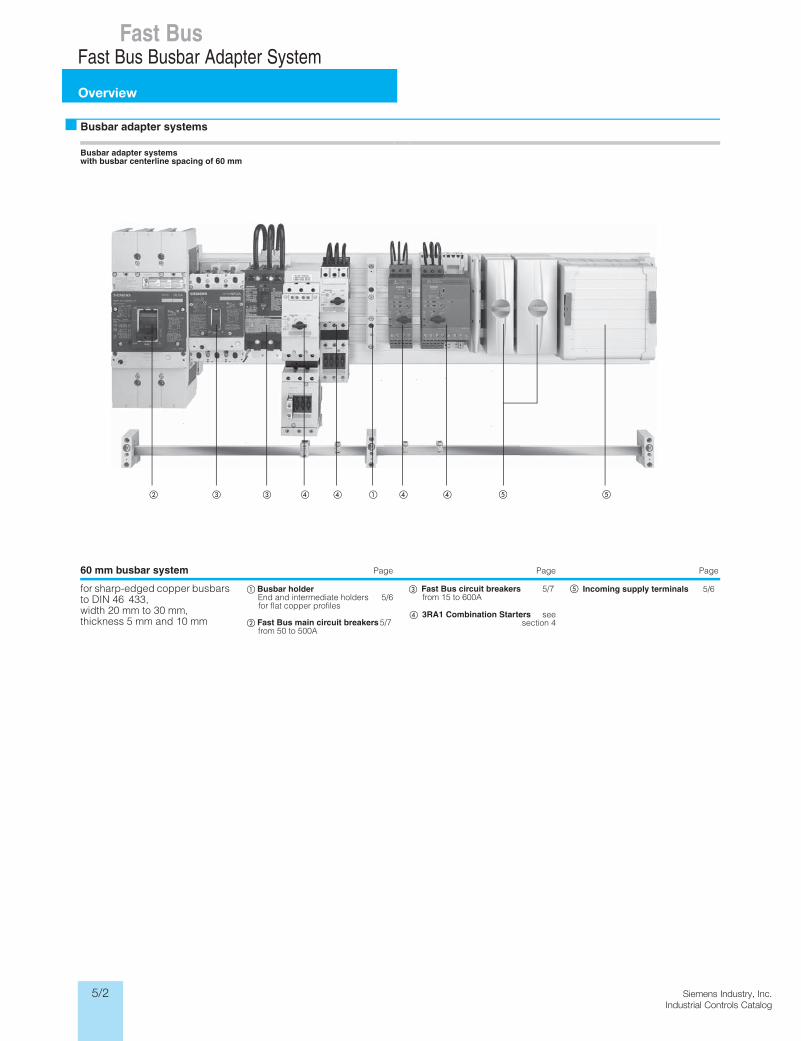
Busbar adapter systems with busbar centerline spacing of 60 mm
60 mm busbar system egaPegaPegaP
for sharp-edged copper busbars to DIN 46 433, width 20 mm to 30 mm, thickness 5 mm and 10 mm
Busbar holderEnd and intermediate holders 5/6for flat copper profiles
Fast Bus main circuit breakers 5/7from 50 to 500A
Fast Bus circuit breakers 5/7from 15 to 600A
3RA1 Combination Starters seesection 4
Incoming supply terminals 5/6
5/3Siemens Industry, Inc.Industrial Controls Catalog
General Features• Simple economical installation
• Compact design
• Requires fewer mounting holes
• Domestic and International approvals
• Touch safe
• Modular design
• Provision for system expansion
• Clip-on shoes provide mechanical and electrical connections to panel mounted busbars
• Main and Feeder breakers mount to busbars
Benefits• Saves installation time
• Reduces space requirements
• Minimizes layout time
• Allows flexibility for domestic and export business
• Protection for maintenance personnel
• Improves equipment mounting density
• Reduces time and costs associated with system expansion
• Reduces mounting and wiring time and provides trouble free connec-tions
• Allows for quick retrofitting of breakers
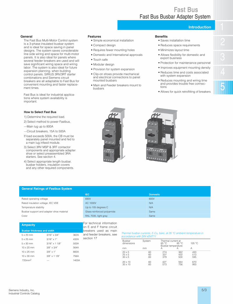
How to Select Fast Bus
1) Determine the required load.
2) Select method to power Fastbus.
—Main lug up to 800A
—Circuit breakers, 15A to 500A
If load exceeds 500A, the CB must be separately panel mounted and fed toa main lug infeed module.
3) Select 3RV MSP & 3RT contactor components and appropriate adapter shoe or select preassembled 3RA starters. See section 4.
4) Select appropriate length busbar, busbar holders, insulation covers and any other required components.
General Ratings of Fastbus System
IEC Domestic
Rated operating voltage 690V 600V
Rated insulation voltage, IEC VDE AC 1000V N/A
Temperature stability Up to 105 degrees C N/A
Busbar support and adapter shoe material Glass-reinforced polyamide Same
Color RAL 7035, light gray Same
Ampacity
Busbar thickness and width
5 x 20 mm 3/16” x 3/4” 362A
5 x 25 mm 3/16” x 1” 432A
5 x 30 mm 3/16” x 1 1/8” 500A
10 x 20 mm 3/8” x 3/4” 564A
10 x 25 mm 3/8” x 1” 660A
10 x 30 mm 3/8” x 1 1/8” 756A
For technical informationon E and F frame circuitbreakers used as mainand feeder breakers, seesection 17
Thermal busbar currents, E-Cu, bare, at 35 °C ambient temperature in accordance with DIN 43 6711
Busbardimensions
mm
System
mm
Thermal current at 65 °C 85 °C 105 °CBusbar temperatureA A A
20 x 525 x 530 x 5
20 x 1030 x 10
606060
6060
274 362 430327 432 513379 500 595
427 564 670573 756 900
The Fast Bus Multi-Motor Control system is a 3-phase insulated busbar system and is ideal for space saving in panel designs. The system saves considerable line side wiring and space for multi-motor panels. It is also ideal for panels where several feeder breakers are used and will save significant wiring space and wiring labor. The system is also ideal for future expansion planning. when building control panels. SIRIUS 3RV/3RT starter combinations and Siemens circuit breakers are all adaptable to Fast Bus for convenient mounting and faster replace-ment times.
Fast Bus is ideal for industrial applica-tions where system availability is important.
720mm2 --- 1400A
Siemens / Industrial Controls Previous folio: 5/3
Fast BusFast Bus Busbar Adapter System
Introduction
5/4 Siemens Industry, Inc.Industrial Controls Catalog
Siemens / Industrial Controls Previous folio: 5/4
Fast BusFast Bus Busbar Adapter System
Introduction
Clearance in air Creepage distance
Between live parts 25.4 mm (1 inch) 50.8 mm (2 inch)
Between live parts and grounded, non-insulated metal parts
25.4 mm (1 inch) 25.4 mm (1 inch)
The short-circuit strength of the busbar system is dependent on the spacing of the busbar hold-ers and on the busbar cross-section.
The short-circuit strength of the whole system is dependent on the short-circuit strength of the busbar system and the componentsthat are mounted to the system.
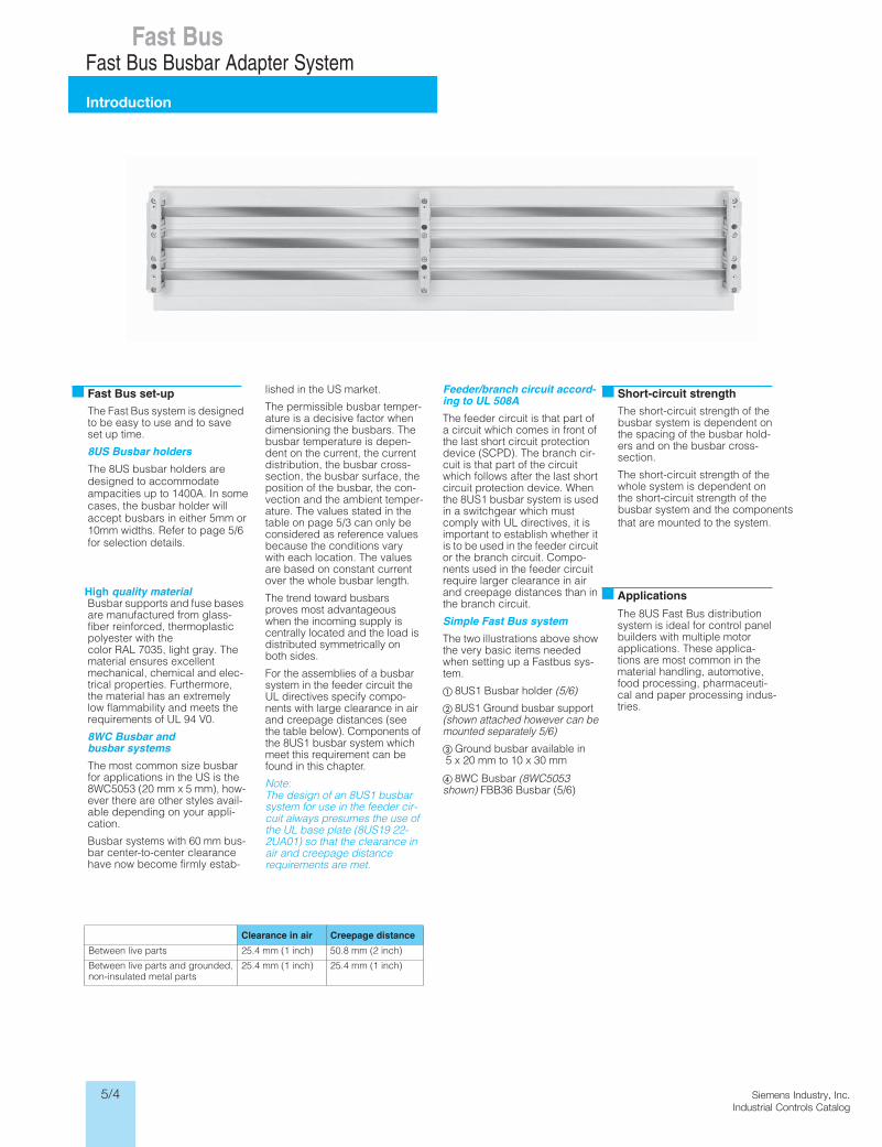
Short-circuit strengthThe Fast Bus system is designedto be easy to use and to save set up time.
8US Busbar holders
The 8US busbar holders are designed to accommodate ampacities up to 1400A. In somecases, the busbar holder willaccept busbars in either 5mm or10mm widths. Refer to page 5/6for selection details.
High quality materialBusbar supports and fuse bases are manufactured from glass-fiber reinforced, thermoplastic polyester with the color RAL 7035, light gray. The material ensures excellent mechanical, chemical and elec-trical properties. Furthermore, the material has an extremely low flammability and meets the requirements of UL 94 V0.
8WC Busbar and busbar systems
The most common size busbar for applications in the US is the 8WC5053 (20 mm x 5 mm), how-ever there are other styles avail-able depending on your appli-cation.
Busbar systems with 60 mm bus-bar center-to-center clearance have now become firmly estab-
Fast Bus set-up lished in the US market.
The permissible busbar temper-ature is a decisive factor when dimensioning the busbars. The busbar temperature is depen-dent on the current, the current distribution, the busbar cross-section, the busbar surface, the position of the busbar, the con-vection and the ambient temper-ature. The values stated in the table on page 5/3 can only be considered as reference values because the conditions vary with each location. The values are based on constant current over the whole busbar length.
The trend toward busbars proves most advantageous when the incoming supply is centrally located and the load is distributed symmetrically on both sides.
For the assemblies of a busbar system in the feeder circuit the UL directives specify compo-nents with large clearance in air and creepage distances (see the table below). Components of the 8US1 busbar system which meet this requirement can be found in this chapter.
Note:The design of an 8US1 busbar system for use in the feeder cir-cuit always presumes the use of the UL base plate (8US19 22-2UA01) so that the clearance in air and creepage distance requirements are met.
Feeder/branch circuit accord-ing to UL 508A
The feeder circuit is that part of a circuit which comes in front of the last short circuit protection device (SCPD). The branch cir-cuit is that part of the circuit which follows after the last short circuit protection device. When the 8US1 busbar system is used in a switchgear which must comply with UL directives, it is important to establish whether it is to be used in the feeder circuit or the branch circuit. Compo-nents used in the feeder circuit require larger clearance in air and creepage distances than in the branch circuit.
Simple Fast Bus system
The two illustrations above show the very basic items needed when setting up a Fastbus sys-tem.
8US1 Busbar holder (5/6)
8US1 Ground busbar support (shown attached however can be mounted separately 5/6)
Ground busbar available in 5 x 20 mm to 10 x 30 mm
8WC Busbar (8WC5053shown) FBB36 Busbar (5/6)
The 8US Fast Bus distribution system is ideal for control panel builders with multiple motor applications. These applica-tions are most common in the material handling, automotive, food processing, pharmaceuti-cal and paper processing indus-tries.
Applications
5/5Siemens Industry, Inc.Industrial Controls Catalog
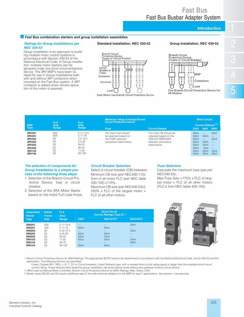
Fast Bus combination starters and group installation assemblies
MSPType
Maximum rating of Group BranchCircuit Protective Device
Short Circuit
Current Ratings 1) 2)
Fuse 240V 600V
3RV2013RV2013RV2023RV2023RV202
0.11-12.50.11-163.5-12.53.5-2528-32
The main fuse should be selected based on the FUSE selection procedure listed below.
Circuit Breaker
The main CB should be selected based on the CIRCUIT BREAKER selection procedure listed below.
65kA65kA65kA65kA65kA
30kA—30kA——
3RV2023RV103
36-4011-50
FLAAmpRange
S00S00S0S0S0S0S2
65kA65kA
—25kA
3RV104 28-100S3 65kA
—65kA—65kA50kA12kA65kA65kA 30kA
The selection of components for Group Installation is a simple pro-cess of the following three steps:1. Selection of the Branch Circuit Pro-
tective Device, fuse or circuitbreaker.
2. Selection of the 3RA Motor Starterbased on the motor Full Load Amps.
Circuit Breaker SelectionSelect a circuit breaker (CB) between:Minimum CB size (per NEC430-110):Sum of all motor FLC (per NEC table430-150) x115%.Maximum CB size (per NEC430-53c):250% x FLC of the largest motor +FLC of all other motors.
Fuse SelectionCalculate the maximum fuse size perNEC430-53c.Max Fuse Size =175% x FLC of larg-est motor + FLC of all other motors(FLC’s from NEC table 430-150).
Ratings for Group Installations per NEC 430-53Group Installation is an approach to build-ing multiple motor control systems in accordance with Section 430-53 of the National Electrical Code. In Group installa-tion, multiple motor starters can be grouped under one short circuit protective device. The 3RV MSP’s have been UL listed for use in Group Installations both with and without 3RT contactors when mounted on the Fast Bus system. A 3RT contactor is added when remote opera-tion of the motor is required.
Standard Installation, NEC 430-52 Group Installation, NEC 430-53
StarterType
FrameSize
AmpRange
Short CircuitAssembled Starter FLACurrent Ratings (Type E) 1)
240V 480Y/277V 600Y/347V
3RA2013RA2013RA202
S00S00S0
0.11-12.50.11-160.45-12.5
—65kA—
—65kA—
30kA—30kA
3RA2023RA2023RA103
S0S0S2
0.45-2528-3211-50
65kA50kA65kA
65kA50kA65kA
——25kA
3RA104 S3 28-75 — — 30kA 3RA104 S3 28-100 65kA 65kA —
FLAAmpRange
1) Branch Circuit Protective Device for 480V-Ratings: The appropriate BCPD need to be determined in accordance with the National Electrical Code, Article 430-53 and the application. The following devices are permitted: Fuses: Classes RK1, RK5, J, G, T, CC or Circuit breakers: Listed Siemens type, with a marked short-circuit rating equal or larger than the available short-circuit current rating. These devices were tested for group installation use at the above levels without any upstream branch circuit device.2) 3RA2 used as Manual Motor Controller; Branch Circuit Protective Device for 600V-Ratings: Max. Class J 50A 3) Starter sizes S00,S0 and S3 require additional type E line side terminal adaptors on the MSP for type F applications. See section 1 accessories
480V
Siemens / Industrial Controls Previous folio: 5/5
Fast BusFast Bus Busbar Adapter System
Introduction
5/6 Siemens Industry, Inc.Industrial Controls Catalog
Product Category: IEC
Siemens / Industrial Controls Previous folio: 5/9 & several
Fast BusFast Bus Busbar Adapter System
60 mm system
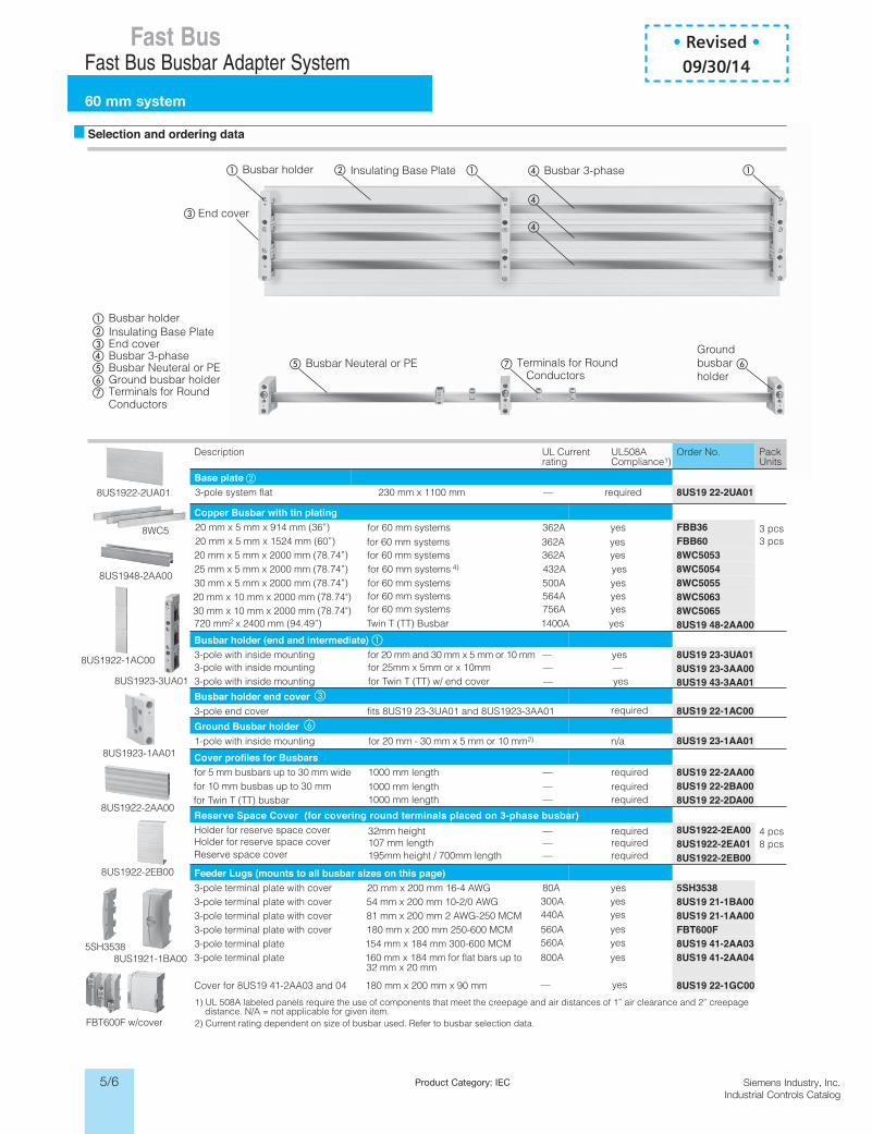
Selection and ordering data
tnerruC LUnoitpircseDrating
UL508ACompliance1)
Order No. PackUnits
Base plate3-pole system flat 230 mm x 1100 mm — required 8US19 22-2UA01
Copper Busbar with tin plating 20 mm x 5 mm x 914 mm (36”) FBB36 3 pcs20 mm x 5 mm x 1524 mm (60”) FBB60 3 pcs20 mm x 5 mm x 2000 mm (78.74”) for 60 mm systems 362A yes 8WC505325 mm x 5 mm x 2000 mm (78.74”) for 60 mm systems 4) 432A yes 8WC505430 mm x 5 mm x 2000 mm (78.74”) for 60 mm systems 500A yes
for 60 mm systems 564A yesfor 60 mm systems 756A yes
8WC505520 mm x 10 mm x 2000 mm (78.74") 8WC506330 mm x 10 mm x 2000 mm (78.74") 8WC5065720 mm2 x 2400 mm (94.49”) Twin T (TT) Busbar 1400A yes 8US19 48-2AA00Busbar holder (end and intermediate) 3-pole with inside mounting for 20 mm and 30 mm x 5 mm or 10 mm — yes 8US19 23-3UA01
3-pole with inside mounting for Twin T (TT) w/ end cover — yes8US19 23-3AA008US19 43-3AA01
Busbar holder end cover3-pole end cover fits 8US19 23-3UA01 and 8US1923-3AA01
3-pole with inside mounting for 25mm x 5mm or x 10mm — —
8US19 22-1AC00Ground Busbar holder1-pole with inside mounting for 20 mm - 30 mm x 5 mm or 10 mm2) n/a
— yes
800A yes
560A yes560A yes
440A yes300A yes
required
8US19 23-1AA01Cover profiles for Busbarsfor 5 mm busbars up to 30 mm wide 1000 mm length — required
1000 mm length — required1000 mm length — required
32mm height — required
8US19 22-2AA00for 10 mm busbas up to 30 mm 8US19 22-2BA00for Twin T (TT) busbar 8US19 22-2DA00Reserve Space Cover (for covering round terminals placed on 3-phase busbar)Holder for reserve space cover
107 mm length — requiredHolder for reserve space cover195mm height / 700mm length — requiredReserve space cover
8US1922-2EA00 4 pcs8 pcs8US1922-2EA01
8US1922-2EB00Feeder Lugs (mounts to all busbar sizes on this page)3-pole terminal plate with cover 20 mm x 200 mm 16-4 AWG 80A yes 5SH35383-pole terminal plate with cover 54 mm x 200 mm 10-2/0 AWG 8US19 21-1BA003-pole terminal plate with cover 81 mm x 200 mm 2 AWG-250 MCM 8US19 21-1AA003-pole terminal plate with cover 180 mm x 200 mm 250-600 MCM FBT600F3-pole terminal plate 154 mm x 184 mm 300-600 MCM 8US19 41-2AA033-pole terminal plate 160 mm x 184 mm for flat bars up to
32 mm x 20 mm8US19 41-2AA04
Cover for 8US19 41-2AA03 and 04 180 mm x 200 mm x 90 mm 8US19 22-1GC00
Busbar holder
Busbar holder
Insulating Base Plate
Insulating Base Plate
End cover
End cover
Busbar 3-phase
Busbar 3-phase
Busbar Neuteral or PE Busbar Neuteral or PEGround busbar holder
Groundbusbarholder
Terminals for Round Conductors
Terminals for Round Conductors
1) UL 508A labeled panels require the use of components that meet the creepage and air distances of 1” air clearance and 2” creepage distance. N/A = not applicable for given item.2) Current rating dependent on size of busbar used. Refer to busbar selection data.FBT600F w/cover
8US1921-1BA00
8US1922-2EB00
8US1922-2AA00
8US1923-1AA01
8US1923-3UA01
8US1922-1AC00
8US1948-2AA00
8WC5
8US1922-2UA01
5SH3538
for 60 mm systems 362A yesfor 60 mm systems 362A yes
• Revised •09/30/14
5/7Siemens Industry, Inc.Industrial Controls Catalog
Product Category: IEC
Siemens / Industrial Controls Previous folio: 5/7
Fast BusFast Bus Busbar Adapter System
60 mm systemCircuit breaker assemblies and kits
Selection and ordering data
Description
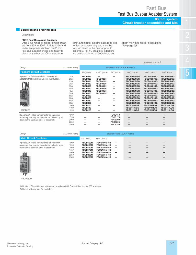
FBCB Fast Bus circuit breakersOffer a full range of feeder circuit break-ers from 15A to 250A. All kits 125A and under are pre-assembled on 60 mm Fast Bus adaptor shoes and ready to place on the busbar. Circuit breakers
150A and higher are pre-packaged kitsfor fast user assembly and must be torqued down to the busbar prior to assembly. For VL breakers, adaptorsare available for up to 500A breakers
(both main and feeder orientation). See page 5/8.
Breaker Frame (SCCR Rating 1))Design
Feeders Circuit Breakers
1) UL Short Circuit Current ratings are ba2) Check Industry Mall for availability.
sed on 480V. Contact Siemens for 600 V ratings.
FBCB100
FBCB250M
FBCB015LGGFBCB015HGGFBCB015NGG——FBCB01515AFBCB020LGGFBCB020HGGFBCB020NGG—FBCB020HFBCB02020AFBCB025LGGFBCB025HGGFBCB025NGG—FBCB025HFBCB02525AFBCB030LGGFBCB030HGGFBCB030NGG—FBCB030HFBCB03030AFBCB035LGGFBCB035HGGFBCB035NGG—FBCB035HFBCB03535AFBCB040LGGFBCB040HGGFBCB040NGG—FBCB040HFBCB04040AFBCB045LGGFBCB045HGGFBCB045NGG—FBCB045HFBCB04545AFBCB050LGGFBCB050HGGFBCB050NGG—FBCB050HFBCB05050AFBCB060LGGFBCB060HGGFBCB060NGG——FBCB06060AFBCB070LGGFBCB070HGGFBCB070NGG——FBCB07070AFBCB080LGGFBCB080HGGFBCB080NGG——FBCB08080AFBCB090LGGFBCB090HGGFBCB090NGG——FBCB09090AFBCB100LGGFBCB100HGGFBCB100NGG——FBCB100100AFBCB110LGGFBCB110HGGFBCB110NGG——FBCB110110AFBCB125LGGFBCB125HGGFBCB125NGG——FBCB125125A
———FBCB150——150A———FBCB175——175A———FBCB200——200A———FBCB225——225A———FBCB250——250A
LGG (65kA)HGG (35kA)NGG (25kA)FXD (65kA)HHED (65kA)ED (25kA)
UL Current Rating
3 pole/600V fully assembled breakers and adaptors that quickly snap onto the Busbar.
Available in 2014 2)
Breaker Frame (SCCR Rating)Design
Main Circuit Breakers
—FBCB100M100A—FBCB125M125A—FBCB150M150A—FBCB175M175A—FBCB200M200A—FBCB225M225A—
———————
———————
———————FBCB250M
FBCB100M-HBFBCB125M-HBFBCB150M-HBFBCB175M-HBFBCB200M-HBFBCB225M-HBFBCB250M-HB250A
HFXD (65kA)FXD (65kA)
UL Current Rating
3 pole/600V kitted components for customer assembly that require the adaptor to be torqued down to the Busbars prior to assembly.
3 pole/600V kitted components for customer assembly that require the adaptor to be torqued down to the Busbars prior to assembly.
5/8 Siemens Industry, Inc.Industrial Controls Catalog
Product Category: IEC
Siemens / Industrial Controls Previous folio: LV16 3/6
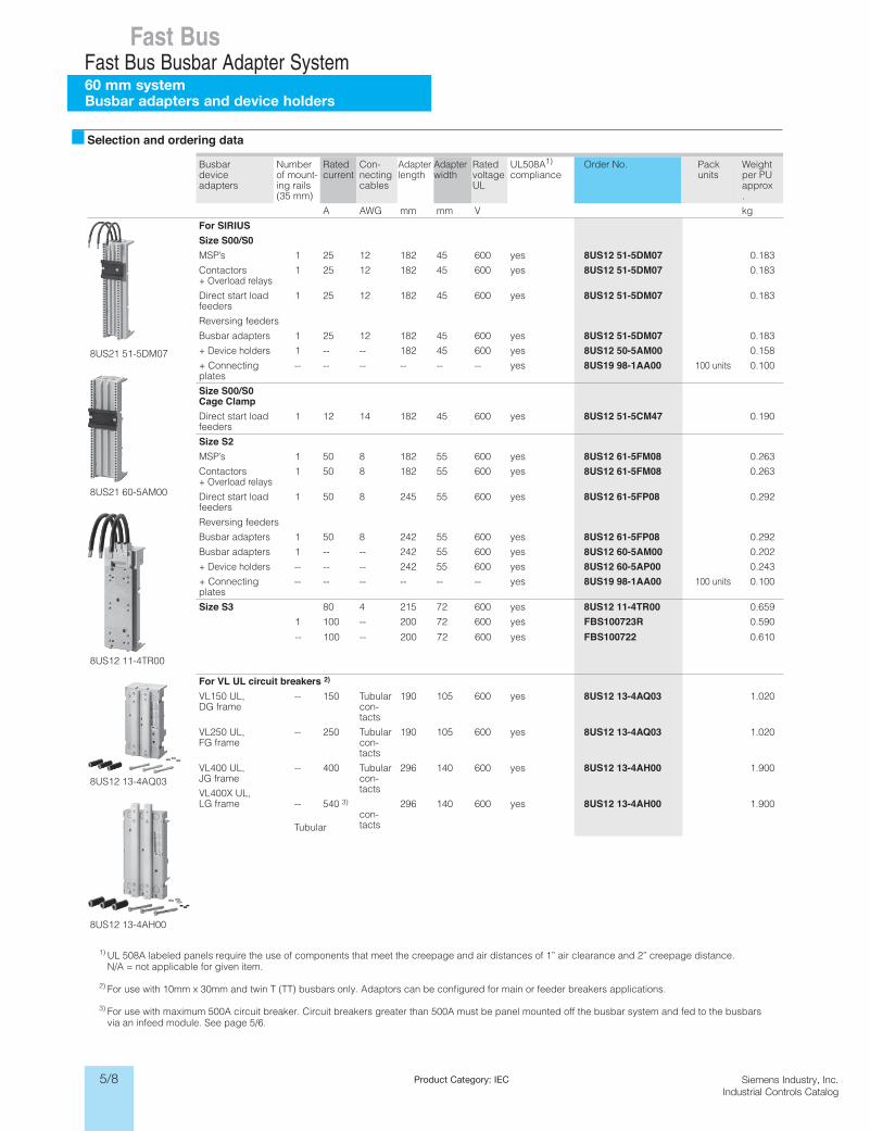
Fast BusFast Bus Busbar Adapter System60 mm systemBusbar adapters and device holders
* You can order this quantity or a multiple thereof.
Selection and ordering data
1) UL 508A labeled panels require the use of components that meet the creepage and air distances of 1” air clearance and 2” creepage distance. N/A = not applicable for given item.
2) For use with 10mm x 30mm and twin T (TT) busbars only. Adaptors can be configured for main or feeder breakers applications.
3) For use with maximum 500A circuit breaker. Circuit breakers greater than 500A must be panel mounted off the busbar system and fed to the busbars via an infeed module. See page 5/6.
Busbardeviceadapters
Numberof mount-ing rails (35 mm)
Ratedcurrent
Con-nectingcables
Adapterlength
Adapterwidth
Ratedvoltage UL
UL508A1)
compliance Order No. Pack
unitsWeight per PU approx.
A AWG mm mm V kg
8US21 51-5DM07
8US21 60-5AM00
8US12 11-4TR00
8US12 13-4AQ03
8US12 13-4AH00
For SIRIUSSize S00/S0MSP’s 1 25 12 182 45 600 yes 8US12 51-5DM07 0.183
Contactors+ Overload relays
1 25 12 182 45 600 yes 8US12 51-5DM07 0.183
Direct start load feeders
1 25 12 182 45 600 yes 8US12 51-5DM07 0.183
Reversing feeders
Busbar adapters 1 25 12 182 45 600 yes 8US12 51-5DM07 0.183
+ Device holders 1 -- -- 182 45 600 yes 8US12 50-5AM00 0.158
+ Connecting plates
-- -- -- -- -- -- yes 8US19 98-1AA00 100 units 0.100
Size S00/S0 Cage ClampDirect start load feeders
1 12 14 182 45 600 yes 8US12 51-5CM47 0.190
Size S2MSP’s 1 50 8 182 55 600 vyes 8US12 61-5FM08 0.263
Contactors+ Overload relays
1 50 8 182 55 600 yes 8US12 61-5FM08 0.263
Direct start load feeders
1 50 8 245 55 600 yes 8US12 61-5FP08 0.292
Reversing feeders
Busbar adapters 1 50 8 242 55 600 yes 8US12 61-5FP08 0.292
Busbar adapters 1 -- -- 242 55 600 yes 8US12 60-5AM00 0.202
+ Device holders -- -- -- 242 55 600 yes 8US12 60-5AP00 0.243
+ Connecting plates
-- -- -- -- -- -- yes 8US19 98-1AA00 100 units 0.100
Size S3 80 4 215 72 600 yes 8US12 11-4TR00 0.659
1 100 -- 200 72 600 yes FBS100723R 0.590
-- 100 -- 200 72 600 yes FBS100722 0.610
For VL UL circuit breakers 2)
VL150 UL, DG frame
-- 150 Tubular con-tacts
190 105 600 yes 8US12 13-4AQ03 1.020
VL250 UL, FG frame
-- 250 Tubular con-tacts
190 105 600 yes 8US12 13-4AQ03 1.020
VL400 UL, JG frame
VL400X UL, LG frame
-- 400 Tubular con-tacts
296 140 600 yes 8US12 13-4AH00 1.900
-- 540 3)
Tubular con-tacts
296 140 600 yes 8US12 13-4AH00 1.900
5/9Siemens Industry, Inc.Industrial Controls Catalog
Product Category: IEC
Siemens / Industrial Controls Previous folio: 5/9
Fast BusFast Bus Busbar Adapter System
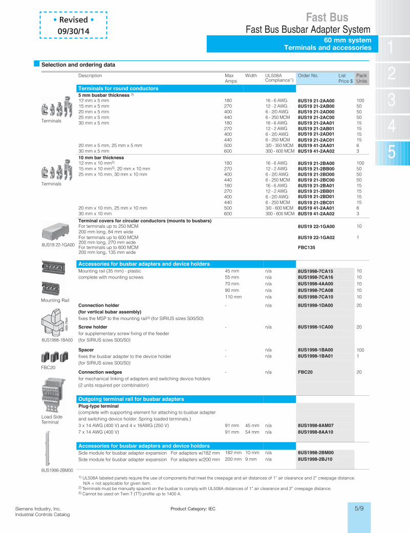
60 mm systemTerminals and accessories
Selection and ordering data
A805LUhtdiWMax Amps
noitpircseDCompliance1)
Order No. List PackPrice $ Units
Terminals for round conductors5 mm busbar thickness
10 mm bar thickness
3)
1008US19 21-2AA00508US19 21-2AB00508US19 21-2AD00508US19 21-2AC00158US19 21-2AA01158US19 21-2AB0115158US19 21-2AC01
8US19 21-2AD01
68US19 41-2AA0138US19 41-2AA02
1008US19 21-2BA00508US19 21-2BB00508US19 21-2BD00508US19 21-2BC00158US19 21-2BA01158US19 21-2BB0115158US19 21-2BC01
8US19 21-2BD01
68US19 41-2AA013
16 - 6 AWG12 - 2 AWG6 - 2/0 AWG6 - 250 MCM16 - 6 AWG12 - 2 AWG6 - 2/0 AWG6 - 250 MCM3/0 - 350 MCM300 - 600 MCM
16 - 6 AWG12 - 2 AWG6 - 2/0 AWG6 - 250 MCM16 - 6 AWG12 - 2 AWG6 - 2/0 AWG6 - 250 MCM3/0 - 600 MCM300 - 600 MCM
180270400440180270400440500600
180270400440180270400440500600
12 mm x 5 mm15 mm x 5 mm20 mm x 5 mm25 mm x 5 mm30 mm x 5 mm
20 mm x 5 mm, 25 mm x 5 mm30 mm x 5 mm
12 mm x 10 mm3)
15 mm x 10 mm3), 20 mm x 10 mm25 mm x 10 mm, 30 mm x 10 mm
20 mm x 10 mm, 25 mm x 10 mm30 mm x 10 mm 8US19 41-2AA02
Accessories for busbar adapters and device holdersa/nmm 54citsalp - )mm 53( liar gnitnuoM 8US1998-7CA15 10a/nmm 55swercs gnitnuom htiw etelpmoc 8US1998-7CA16 10
70 mm n/a 8US1998-4AA00 1090 mm n/a 8US1998-7CA08 10110 mm n/a 8US1998-7CA10 10
Connection holder - n/a 8US1998-1DA00 20(for vertical bubar assembly)fixes the MSP to the mounting rail3) (for SIRIUS sizes S00/S0)
Screw holder - n/a 8US1998-1CA00 20
100
for supplementary screw fixing of the feeder(for SIRIUS sizes S00/S0)
Spacer - n/a 8US1998-1BA00fixes the busbar adapter to the device holder (for SIRIUS sizes S00/S0)
Connection wedges - n/a FBC20 20for mechanical linking of adapters and switching device holders(2 units required per combination)
Outgoing terminal rail for busbar adaptersPlug-type terminal(complete with supporting element for attaching to busbar adapterand switching device holder. Spring loaded terminals.)3 x 14 AWG (400 V) and 4 x a/nmm 54mm 19)V 052( GWA61 8US1998-8AM07
a/nmm 45mm 19)V 004( GWA 41 x 7 8US1998-8AA10
Accessories for busbar adapters and device holdersSide module for busbar adapter expansion For adapters w/182 mm 182 mm 10 mm n/a 8US1998-2BM00Side module for busbar adapter expansion For adapters w/200 mm 200 mm 9 mm n/a 8US1998-2BJ10
Terminal covers for circular conductors (mounts to busbars)108US19 22-1GA00
18US19 22-1GA02
For terminals up to 250 MCM200 mm long, 84 mm wide
200 mm long, 270 mm wideFor terminals up to 600 MCM
FBC135200 mm long, 135 mm wideFor terminals up to 600 MCM
1) UL508A labeled panels require the use of components that meet the creepage and air distances of 1” air clearance and 2” creepage distance. N/A = not applicable for given item.2) Terminals must be manually spaced on the busbar to comply with UL508A distances of 1” air clearance and 2” creepage distance.3) Cannot be used on Twin T (TT) profile up to 1400 A.
Terminals
Terminals
8US19 22-1GA00
Mounting Rail
8US1998-1BA00
FBC20
Load SideTerminal
8US1998-2BM00
1- n/a 8US1998-1BA01
• Revised •09/30/14
5/10 Siemens Industry, Inc.Industrial Controls Catalog
Siemens / Industrial Controls Previous folio: new
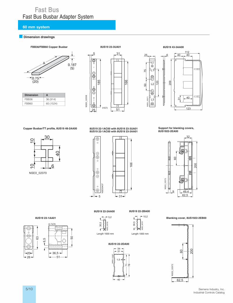
Fast BusFast Bus Busbar Adapter System
60 mm system
Dimension AFBB36 36 (914)
FBB60 60 (1524)
Dimension drawings
L1
L2
L3
NS
E0_
0207
1
31 40
123
209
40 40112
120
7550
25 6
L1
L 2
L3
NS
E0_
0205
8
01573
166
31
51
5
25
185
NSE0_02070
30
40
1010 6
62,549,4
NS
E0_
0207
3
200
32
9
60
62,5
NS
E0_
0207
2
200
60
FBB36/FBB60 Copper Busbar 8US19 23-3UA01 8US19 43-3AA00
Copper Busbar/TT profile, 8US19 48-2AA00 8US19 22-1AC00 with 8US19 23-3UA018US19 22-1AC00 with 8US19 23-3AA01
Support for blanking covers, 8US1922-2EA00
8US19 23-1AA01 Blanking cover, 8US1922-2EB00
NSE0
_007
20
5,2
30,5
Length 1000 mm
10,2
30,5
NSE0
_007
21
Length 1000 mm
1,5
3431
40
71 78
NSE
0_01
607
8US19 22-2AA00 8US19 22-2BA00
8US19 22-2DA00
5/11Siemens Industry, Inc.Industrial Controls Catalog
Siemens / Industrial Controls Previous folio: new
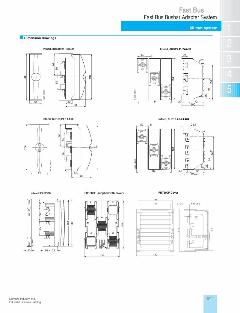
Fast BusFast Bus Busbar Adapter System
60 mm system
Dimension drawingsN
SE
0_02
060
194
8832
6060
94
200
54
NS
E0_
0205
9
194
8832
6060
94
200
81
NS
E0_
0207
4
50
154
2
184
72100
21
28
3696
156
28,7
8,8100,2
50 5
148
8828
7218
4160
NS
E0_
0205
3
Infeed, 8US19 21-1BA00 Infeed, 8US19 41-2AA03
Infeed, 8US19 21-1AA00 Infeed, 8US19 41-2AA04
FBT600F (supplied with cover)
166
146
180
FBT600F Cover
20 28
6034
60
32
200
194
I2_1
3999
a
Infeed 5SH3538
5/12 Siemens Industry, Inc.Industrial Controls Catalog
Siemens / Industrial Controls Previous folio: new
Fast BusFast Bus Busbar Adapter System
60 mm system
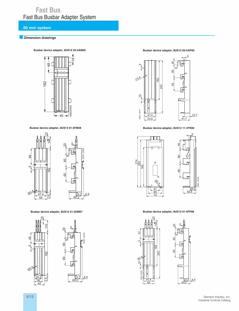
Dimension drawings
3,4
47,453,8
23,751,7N
SE
0_
02
051
510
182
242
5
2060
606
26,554,5
Ø2,5
NS
E0
_0
20
68
4060
60
5
416072
16420
0214
8,547,4
Ø3,4
23,760,2
NS
E0
_0
20
6153
510
148
1218
224
2
54
2060
606
5
Ø3,48,523,7
60,22,947,4
NS
E0
_0
20
62
5
12
20668
182
54
148
5
6060
Ø3,5
8,523,760,22,
529,5
NS
E0
_0
20
63
5
10
20648
182
3645
170
6060
5
Busbar device adapter, 8US12 50-5AM00 Busbar device adapter, 8US12 60-5AP00
Busbar device adapter, 8US12 61-5FM08 Busbar device adapter, 8US12 11-4TR00
Busbar device adapter, 8US12 51-5DM07 Busbar device adapter, 8US12 61-5FP08
5/13Siemens Industry, Inc.Industrial Controls Catalog
Siemens / Industrial Controls Previous folio: new
Fast BusFast Bus Busbar Adapter System
60 mm systemN
SE
0_02
069
14
64
3
4232
14
182
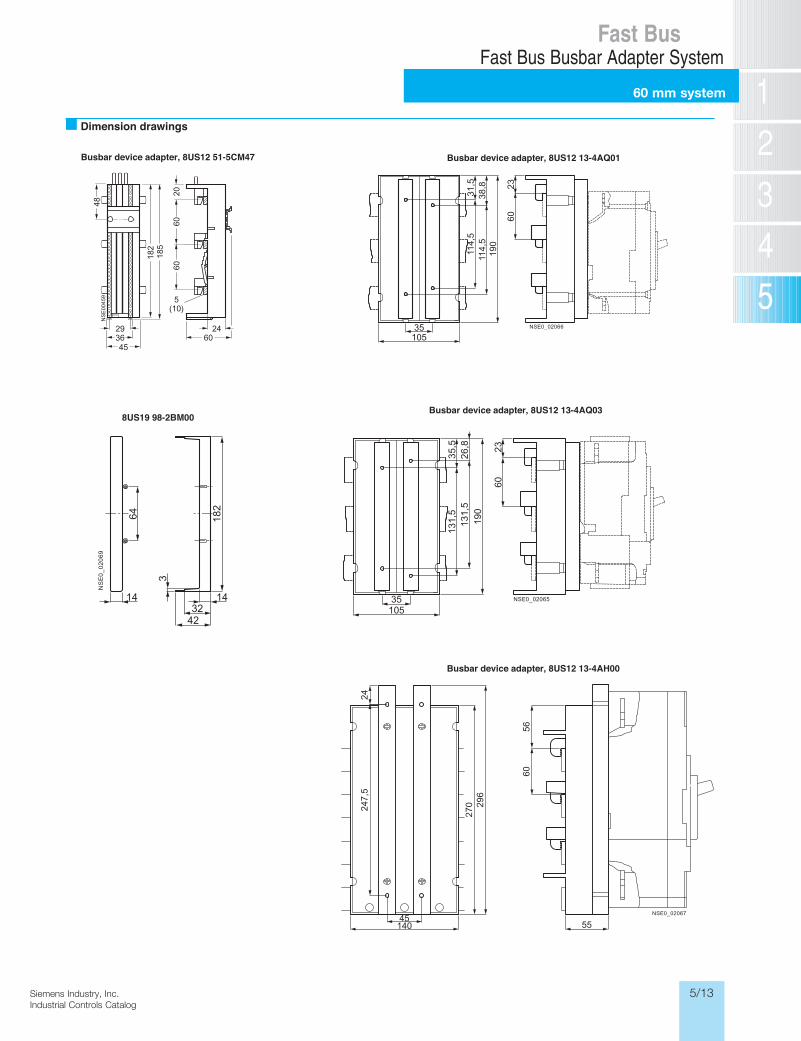
Dimension drawings
38,8
31,5
114,
511
4,5
NSE0_0206635105
190
2360
26,8
35,5
131,
513
1,5
NSE0_0206535105
190
2360
247,
5
NSE0_02067
24
140
270 29
6
45
5660
55
Busbar device adapter, 8US12 51-5CM47 Busbar device adapter, 8US12 13-4AQ01
8US19 98-2BM00Busbar device adapter, 8US12 13-4AQ03
Busbar device adapter, 8US12 13-4AH00
5/14 Siemens Industry, Inc.Industrial Controls Catalog
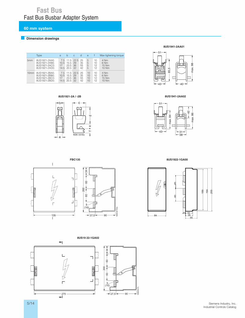
Dimension drawings
Type a b c d e f
8US1921-2AA0.8US1921-2AB0.8US1921-2AC0.8US1921-2AD0.
7.510.51714.5
11.515.523.520.5
22.5293632
25355542
5555
10101212
8US1921-2BA0.
5mm
10mm8US1921-2BB0.8US1921-2BC0.8US1921-2BD0.
Max tighening torque
4 Nm6 Nm15 Nm10 Nm
4 Nm6 Nm15 Nm10 Nm
7.510.51714.5
11.515.523.520.5
22.5293632
25355542
10101010
10101212
8US1941-2AA01
8US1941-2AA028US1921-2A / -2B
FBC135 8US1922-1GA00
8US19 22-1GA02
200
194
32
6060
189
3555
1084
43
85,5
40
max
. 98
51
43
max
. 84
3138
42
51
max
. 86
Siemens / Industrial Controls Previous folio: new
Fast BusFast Bus Busbar Adapter System
60 mm system
5/15Siemens Industry, Inc.Industrial Controls Catalog
Siemens / Industrial Controls Previous folio: new
Fast BusFast Bus Busbar Adapter System
60 mm system
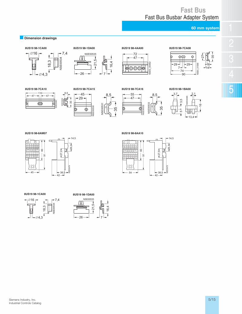
Dimension drawings
8US19 98-1CA00 8US19 98-1DA00 8US19 98-4AA00 8US19 98-7CA08
8US19 98-7CA10 8US19 98-7CA15 8US19 98-7CA16 8US19 98-1BA00
01AA8-89 91SU870MA8-89 91SU8
29
7490
729 9
14
27 35
NS
E0_
0159
98US19 98-1CA00 8US19 98-1DA00
5/16 Siemens Industry, Inc.Industrial Controls Catalog
Fast BusSIRIUS 3RA Fast Bus Combination Starters and Group Installation Assemblies
General data
Combination Starters & Starters for Group InstallationSIRIUS 3RA2 Motor Starters
General data
6/10 SIRIUS Innovations Supplement 2012
6
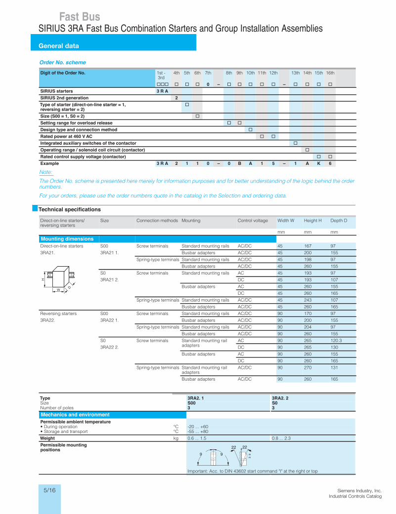
Order No. scheme
Note:
The Order No. scheme is presented here merely for information purposes and for better understanding of the logic behind the order numbers.
For your orders, please use the order numbers quote in the catalog in the Selection and ordering data.
Technical specifications
Digit of the Order No. 1st - 3rd
4th 5th 6th 7th 8th 9th 10th 11th 12th 13th 14th 15th 16th
@@@ @ @ @ 0 – @ @ @ @ @ – @ @ @ @SIRIUS starters 3 R ASIRIUS 2nd generation 2Type of starter (direct-on-line starter = 1,reversing starter = 2)
@
Size (S00 = 1, S0 = 2) @Setting range for overload release @ @Design type and connection method @Rated power at 460 VAC @ @Integrated auxiliary switches of the contactor @Operating range / solenoid coil circuit (contactor) @Rated control supply voltage (contactor) @ @Example 3 R A 2 1 1 0 – 0 B A 1 5 – 1 A K 6
Direct-on-line starters/reversing starters
Size Connection methods Mounting Control voltage Width W Height H Depth D
mm mm mm
Mounting dimensionsDirect-on-line starters
3RA21.
S00
3RA21 1.
Screw terminals Standard mounting rails AC/DC 45 167 97
Busbar adapters AC/DC 45 200 155
Spring-type terminals Standard mounting rails AC/DC 45 198 97
Busbar adapters AC/DC 45 260 155
S0
3RA21 2.
Screw terminals Standard mounting rails AC 45 193 97
DC 45 193 107
Busbar adapters AC 45 260 155
DC 45 260 165
Spring-type terminals Standard mounting rails AC/DC 45 243 107
Busbar adapters AC/DC 45 260 165
Reversing starters
3RA22.
S00
3RA22 1.
Screw terminals Standard mounting rails AC/DC 90 170 97
Busbar adapters AC/DC 90 200 155
Spring-type terminals Standard mounting rails AC/DC 90 204 97
Busbar adapters AC/DC 90 260 155
S0
3RA22 2.
Screw terminals Standard mounting rail adapters
AC 90 265 120.3
DC 90 265 130
Busbar adapters AC 90 260 155
DC 90 260 165
Spring-type terminals Standard mounting rail adapters
AC/DC 90 270 131
Busbar adapters AC/DC 90 260 165
W
H
D
Type 3RA2. 1 3RA2. 2 eziS S00 S0 selop fo rebmuN 3 3
Mechanics and environment
Permissible ambient temperatureC°noitarepo gniruD• -20 ... +60C°tropsnart dna egarotS• -55 ... +80
Weight kg 0.6 ... 1.5 0.8 ... 2.3
Permissible mountingpositions
Important: Acc. to DIN 43602 start command "I" at the right or topShock resistance (sine-wave pulse)
Acc. to IEC 60086 Part 2-27 g Up to 6 Up to 6
Degree of protection Acc. to IEC 60947-1 IP20
9 9
39
22 22
LV1N_06_02.fm Page 10 Tuesday, September 24, 2013 10:52 AM
5/17Siemens Industry, Inc.Industrial Controls Catalog
Siemens / Industrial Controls Previous folio: 5/20
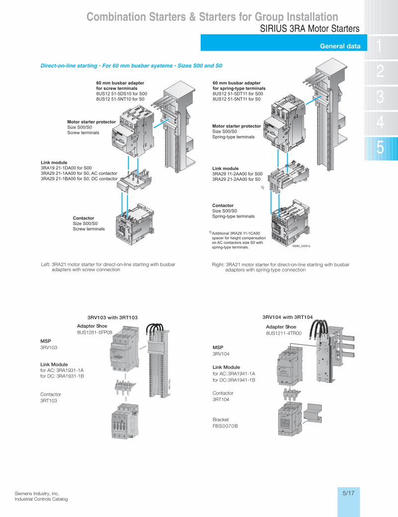
Direct-on-line starting • For 60 mm busbar systems • Sizes S00 and S0
Left: 3RA21 motor starter for direct-on-line starting with busbar adapters with screw connection
Right: 3RA21 motor starter for direct-on-line starting with busbar adapters with spring-type connection
NSB0_02091a
60 mm busbar adapterfor screw terminals8US12 51-5DS10 for S008US12 51-5NT10 for S0
Motor starter protectorSize S00/S0Screw terminals
Link module3RA19 21-1DA00 for S003RA29 21-1AA00 for S0, AC contactor3RA29 21-1BA00 for S0, DC contactor
ContactorSize S00/S0Screw terminals
60 mm busbar adapterfor spring-type terminals8US12 51-5DT11 for S008US12 51-5NT11 for S0
Motor starter protectorSize S00/S0Spring-type terminals
Link module3RA29 11-2AA00 for S003RA29 21-2AA00 for S0
ContactorSize S00/S0Spring-type terminals
Additional 3RA29 11-1CA00spacer for height compensationon AC contactors size S0 withspring-type terminals.
1)
1)
MSP3RV103
Link Modulefor AC: 3RA1931-1Afor DC: 3RA1931-1B
Contactor3RT103
3RV103 with 3RT103
Adapter Shoe8US1261-5FP08
MSP3RV104
Link Modulefor AC: 3RA1941-1Afor DC: 3RA1941-1B
Contactor3RT104
BracketFBS0070B
3RV104 with 3RT104
Adapter Shoe8US1211-4TR00
Combination Starters & Starters for Group InstallationSIRIUS 3RA Motor Starters
General data
5/18 Siemens Industry, Inc.Industrial Controls Catalog
Siemens / Industrial Controls Previous folio: 5/21
Fast BusSIRIUS 3RA Fast Bus Combination Starters and Group Installation Assemblies
Selection
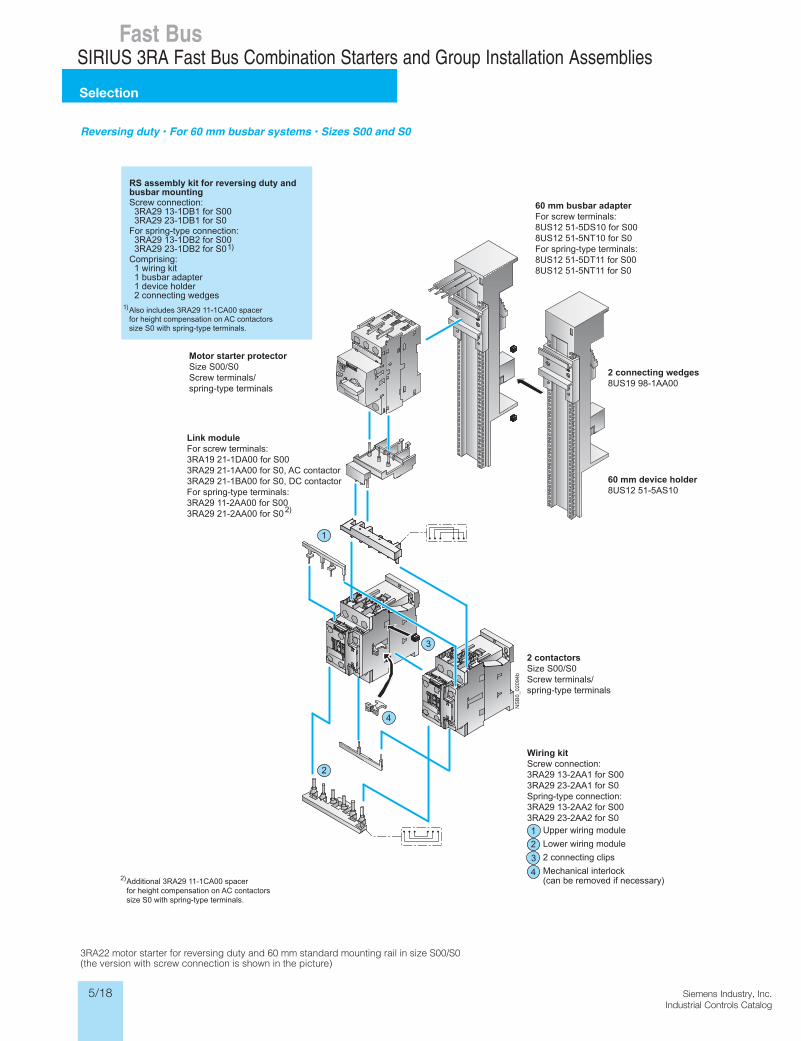
Reversing duty • For 60 mm busbar systems • Sizes S00 and S0
3RA22 motor starter for reversing duty and 60 mm standard mounting rail in size S00/S0 (the version with screw connection is shown in the picture)
NS
B0_
0209
4b
3
4
1
2
Motor starter protectorSize S00/S0Screw terminals/spring-type terminals
2 contactorsSize S00/S0Screw terminals/spring-type terminals
Wiring kitScrew connection:3RA29 13-2AA1 for S003RA29 23-2AA1 for S0Spring-type connection:3RA29 13-2AA2 for S003RA29 23-2AA2 for S0
Upper wiring module
Lower wiring module
2 connecting clips
Mechanical interlock(can be removed if necessary)
3
4
1
2
RS assembly kit for reversing duty andbusbar mountingScrew connection: 3RA29 13-1DB1 for S00 3RA29 23-1DB1 for S0For spring-type connection: 3RA29 13-1DB2 for S00 3RA29 23-1DB2 for S0Comprising: 1 wiring kit 1 busbar adapter 1 device holder 2 connecting wedges
Link moduleFor screw terminals:3RA19 21-1DA00 for S003RA29 21-1AA00 for S0, AC contactor3RA29 21-1BA00 for S0, DC contactorFor spring-type terminals:3RA29 11-2AA00 for S003RA29 21-2AA00 for S0
Additional 3RA29 11-1CA00 spacerfor height compensation on AC contactorssize S0 with spring-type terminals.
60 mm busbar adapterFor screw terminals:8US12 51-5DS10 for S008US12 51-5NT10 for S0For spring-type terminals:8US12 51-5DT11 for S008US12 51-5NT11 for S0
2 connecting wedges8US19 98-1AA00
60 mm device holder8US12 51-5AS10
Also includes 3RA29 11-1CA00 spacerfor height compensation on AC contactorssize S0 with spring-type terminals.
1)
1)
2)
2)
5/19Siemens Industry, Inc.Industrial Controls Catalog
Siemens / Industrial Controls Previous folio: 5/22
bu
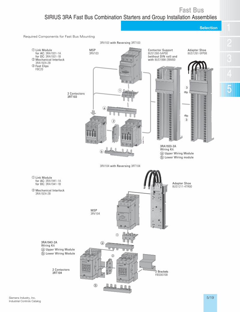
2BracketsFBS0070B
aLinkModuleforAC:3RA1941-1AforDC:3RA1941-1B
bMechanicalInterlock3RA1924-2B
3RA1943-2AWiringKitauUpperWiringModulebuLowerWiringModule
2Contactors3RT104
MSP3RV104
au
a
b
AdapterShoe8US1211-4TR00
3RV104 withReversing 3RT104
3RA1933-2AWiringKitauUpperWiringModulebuLowerWiringmodule
2Contactors3RT103
aLinkModuleforAC:3RA1931-1AforDC:3RA1931-1B
bMechanicalInterlock3RA1924-2B
cFastClipsFBC20
ContactorSupport8US1260-5AP00 (withoutDINrail)and with8US1998-2BM00
AdapterShoe8US1261-5FP08
MSP3RV103
Required Components for Fast Bus Mounting
3RV103 withReversing 3RT103
Fast BusSIRIUS 3RA Fast Bus Combination Starters and Group Installation Assemblies
Selection
5/20 Siemens Industry, Inc.Industrial Controls Catalog
Siemens / Industrial Controls Previous folio: 5/25
45
169.
9
49
96.95
3RA2210-0.A1.-2AP0
45
200
154.9
All dimensions are in millimeters (mm)Alle Bemassungswerte sind in Millimeter (mm) angegeben.
3RA2110-0.D1.-1AP0
Massstab/Scale:Format/Size: DIN A4 1:2
45
193.
4
49
96.997
5
3RA2120-1.A24-0AP0
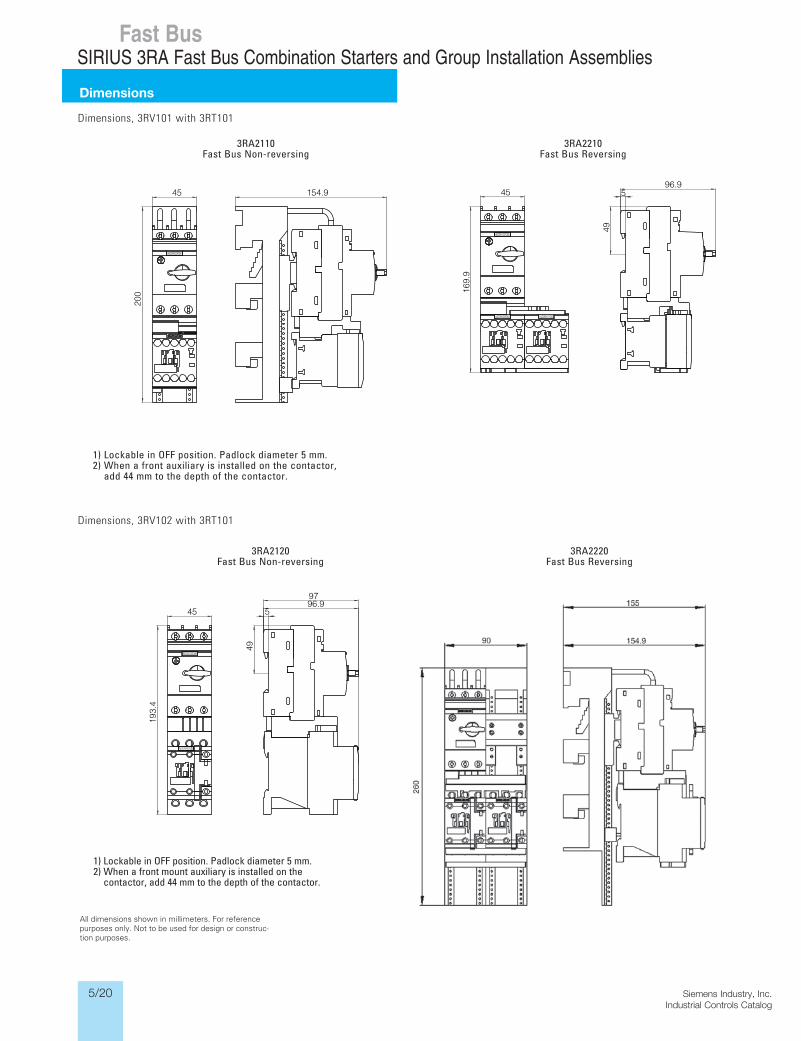
3RA2110FastBusNon-reversing
3RA2210FastBusReversing
Dimensions, 3RV101 with 3RT101
3RA2120FastBusNon-reversing
3RA2220FastBusReversing
Dimensions, 3RV102 with 3RT101
All dimensions shown in millimeters. For reference purposes only. Not to be used for design or construc-tion purposes.
1)LockableinOFFposition.Padlockdiameter5mm. 2)Whenafrontmountauxiliaryisinstalledonthe
contactor,add44mmtothedepthofthecontactor.
1)LockableinOFFposition.Padlockdiameter5mm. 2)Whenafrontauxiliaryisinstalledonthecontactor,
add44mmtothedepthofthecontactor.
Fast BusSIRIUS 3RA Fast Bus Combination Starters and Group Installation Assemblies
Dimensions
5/21Siemens Industry, Inc.Industrial Controls Catalog
Siemens / Industrial Controls Previous folio: 5/26
3)
NS
K-8
174
259
309
10 55
7 1817
6895
142
1828
DC 157176
3453
14
SIEMENS
SIEMENS
2)
1)
259
2)
309
10120
17.5N
SK-8
175
10
SIEMENS
SIEMENSSIEMENS
1)
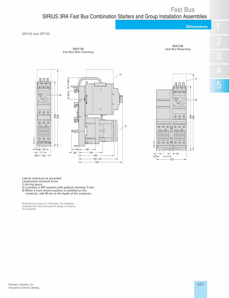
Lateralclearancetogroundedcomponentsminimum6mm.1)Arcingspace2)LockableinOFFpositionwithpadlockdiameter5mm.3)Whenafrontmountauxiliaryisinstalledonthe
contactor,add49mmtothedepthofthecontactor.
All dimensions shown in millimeters. For reference purposes only. Not to be used for design or construc-tion purposes.
3RA1130FastBusNon-reversing
3RA1230FastBusReversing
3RV103 with 3RT103
Fast BusSIRIUS 3RA Fast Bus Combination Starters and Group Installation Assemblies
Dimensions

5/22 Siemens Industry, Inc.Industrial Controls Catalog
Siemens / Industrial Controls Previous folio: 5/27
All dimensions shown in millimeters. For reference purposes only. Not to be used for design or construc-tion purposes.
3RV104 with 3RT104
Lateralclearancetogroundedcomponentsminimum6mm.1)Arcingspace2)LockableinOFFpositionwithpadlockdiameter5mm.3)Whenafrontmountauxiliaryisinstalledonthe
contactor,add49mmtothedepthofthecontactor.
Fast BusSIRIUS 3RA Fast Bus Combination Starters and Group Installation Assemblies
Dimensions