Boiling heat transfer and critical heat flux in liquid ...such as thin film evaporators,...
13
Boiling heat transfer and critical heat flux in liquid films falling on vertically-mounted heat sources I. A. MUDAWWAR, T. A. INCROPERA and F. P. INCROPERA Heat Transfer Laboratory, School of Mechanical Engineering, Purdue University, West Lafayette, IN 47907, U.S.A. (Received I1 September 1986 and infinalform 4 March 1987) Abstract-Boiling heat transfer measurements were obtained for an inert fluorocarbon (FC-72) liquid him injected over a vertical heated wall. Flow visualization revealed that vigorous boiling prior to burnout ruptured the liquid continuum, causing most of the film to separate from the heated wall leaving a thin liquid subfilm which maintained contact with the wall. The critical heat flux (CHF) was accompanied by dryout of the subfilm after total separation of the liquid near the upstream edge of the heater. A higher CHF was achieved by increasing the film velocity or by utilizing a shorter heater. Experimental data correlated favorably with predictions of a CHF model based on the Helmholtz instability and subfilm dryout. INTRODUCTION A FUNDAMENTAL understanding of boiling heat trans- fer in thin liquid films is important to applications such as thin film evaporators, water-cooled turbine blades, nuclear fuel rods, and laser mirrors. Thin films are utilized in a variety of cooling colorations. Examples include horizontal stationary films, gravity- driven films, shear-driven (annular-flow) films, wall jets, and radial films formed by jet impingement. According to Mesler [I], nucleate boiling in a thin liquid film reduces the wall superheat compared to pool boiling. This behavior was attributed to the short trajectory a bubble needs to traverse within a thin film before escaping at the free surface. The nucleation pattern contrasts sharply with that of pool boiling, where a bubble establishes a long trajectory along which it experiences considerable resistance by liquid inertia. Furthermore, the enormous growth of bub- bles along trajectories in a liquid pool provides a resistance for liquid flow to the hot wall. An important aspect of heat transfer enhancement in thin boiling films concerns microlayer evaporation. As a bubble grows in any boiling system, it tends to trap a thin liquid layer (microlayer) between the growing bubble and the heated wall. Since the thick- ness of this layer is typically of the order of 1 pm [2], it provides a highly conductive path for heat dis- sipated at the wall. This heat is rejected by evaporation of the microlayer surface. Microlayer evaporation is a major contributor to increasing the heat transfer coefficient associated with boiling [3,4]. In pool boil- ing the contact time of the bubble with the surface is long enough for the microlayer to evaporate com- pletely, and microlayer evaporation is nonexistent for a considerable fraction of the bubble history prior to detachment. In thin boiling films, on the other hand, bubbles detach from the hot wall before the micro- layer has time to dryout. Therefore, microlayer evaporation is active over a larger fraction of the bubble contact time, and higher heat fluxes may be achieved for the same wall superheat. ~though microlayer evapo~tion may provide an explanation for nucleate boiling enhancement in thin stationary horizontal films, flowing films may exhibit different nucleation patterns due to the strong itiu- ence of liquid motion on the growing bubbles. Ueda et at. [S] indicated that bubbles growing within a low velocity, gravity-driven film burst directly through the film surface. Bubbles in high speed fihns, on the other hand, are dragged along with the liquid stream instead of growing and bursting at the active nucleation sites. Thus microlayer evaporation is very important near the upstream edge of the hot wall. Further downstream, the large void fraction within the film caused by entrainment of a large ~puIation of bub- bles thickens the film significantly and endangers the existence of a liquid continuum near the hot wall. Thus the attractive nucleate boiling capabilities of high speed films deteriorate rapidly when employed with long heated surfaces. The similarity of the CHF mechanism in most flow- ing film geometries (falling films, shear-driven films, wall jets, impinging jets) is evidenced by the optical studies and visual observations of several inves- tigators [5-121. In one such effort, Katto and Ishii [9] experimented with a liquid jet driven by a nozzle at an angle to the surface of a rectangular heater. They witnessed noticeable thickening of the boiling film in the flow direction due to the entrainment of bubbles by the jet. At higher heat fluxes the greater part of the liquid was driven from the hot wall by intense vapor 2083
Transcript of Boiling heat transfer and critical heat flux in liquid ...such as thin film evaporators,...
Boiling heat transfer and critical heat flux in liquid films falling on
vertically-mounted heat sources I. A. MUDAWWAR, T. A. INCROPERA and F. P. INCROPERA
Heat Transfer Laboratory, School of Mechanical Engineering, Purdue University, West Lafayette, IN 47907, U.S.A.
(Received I1 September 1986 and infinalform 4 March 1987)
Abstract-Boiling heat transfer measurements were obtained for an inert fluorocarbon (FC-72) liquid him injected over a vertical heated wall. Flow visualization revealed that vigorous boiling prior to burnout ruptured the liquid continuum, causing most of the film to separate from the heated wall leaving a thin liquid subfilm which maintained contact with the wall. The critical heat flux (CHF) was accompanied by dryout of the subfilm after total separation of the liquid near the upstream edge of the heater. A higher CHF was achieved by increasing the film velocity or by utilizing a shorter heater. Experimental data correlated favorably with predictions of a CHF model based on the Helmholtz instability and subfilm
dryout.
INTRODUCTION
A FUNDAMENTAL understanding of boiling heat trans- fer in thin liquid films is important to applications such as thin film evaporators, water-cooled turbine blades, nuclear fuel rods, and laser mirrors. Thin films are utilized in a variety of cooling colorations. Examples include horizontal stationary films, gravity- driven films, shear-driven (annular-flow) films, wall jets, and radial films formed by jet impingement.
According to Mesler [I], nucleate boiling in a thin liquid film reduces the wall superheat compared to pool boiling. This behavior was attributed to the short trajectory a bubble needs to traverse within a thin film before escaping at the free surface. The nucleation pattern contrasts sharply with that of pool boiling, where a bubble establishes a long trajectory along which it experiences considerable resistance by liquid inertia. Furthermore, the enormous growth of bub- bles along trajectories in a liquid pool provides a resistance for liquid flow to the hot wall.
An important aspect of heat transfer enhancement in thin boiling films concerns microlayer evaporation. As a bubble grows in any boiling system, it tends to trap a thin liquid layer (microlayer) between the growing bubble and the heated wall. Since the thick- ness of this layer is typically of the order of 1 pm [2], it provides a highly conductive path for heat dis- sipated at the wall. This heat is rejected by evaporation of the microlayer surface. Microlayer evaporation is a major contributor to increasing the heat transfer coefficient associated with boiling [3,4]. In pool boil- ing the contact time of the bubble with the surface is long enough for the microlayer to evaporate com- pletely, and microlayer evaporation is nonexistent for a considerable fraction of the bubble history prior to
detachment. In thin boiling films, on the other hand, bubbles detach from the hot wall before the micro- layer has time to dryout. Therefore, microlayer evaporation is active over a larger fraction of the bubble contact time, and higher heat fluxes may be achieved for the same wall superheat.
~though microlayer evapo~tion may provide an explanation for nucleate boiling enhancement in thin stationary horizontal films, flowing films may exhibit different nucleation patterns due to the strong itiu- ence of liquid motion on the growing bubbles. Ueda et at. [S] indicated that bubbles growing within a low velocity, gravity-driven film burst directly through the film surface. Bubbles in high speed fihns, on the other hand, are dragged along with the liquid stream instead of growing and bursting at the active nucleation sites. Thus microlayer evaporation is very important near the upstream edge of the hot wall. Further downstream, the large void fraction within the film caused by entrainment of a large ~puIation of bub- bles thickens the film significantly and endangers the existence of a liquid continuum near the hot wall. Thus the attractive nucleate boiling capabilities of high speed films deteriorate rapidly when employed with long heated surfaces.
The similarity of the CHF mechanism in most flow- ing film geometries (falling films, shear-driven films, wall jets, impinging jets) is evidenced by the optical studies and visual observations of several inves- tigators [5-121. In one such effort, Katto and Ishii [9] experimented with a liquid jet driven by a nozzle at an angle to the surface of a rectangular heater. They witnessed noticeable thickening of the boiling film in the flow direction due to the entrainment of bubbles by the jet. At higher heat fluxes the greater part of the liquid was driven from the hot wall by intense vapor
2083
2084 1. A. MIJIIAWWAR CI d
.__ ______
NOMENCLATURE
A total heat transfer area A r,,, wall superheat
A, total cross-sectional area of vapor jets A T,,k> wall subcooling cp:pr specific heat ofliquid at constant pressure li average film speed c sub constant in equation (12) 111 velocity of liquid normal to the hot wall
C.? constant in equation (6) 11, velocity of vapor normal to the hot wail.
9 acceleration due to gravity h fg latent heat of vaporization Greek symbols
kr thermal conductivity of the saturated 5 nozzle spacing liquid ()%I thickness of liquid subfilm
L heater length ‘.H critical wavelength for Helmholtz
4 wall heat flux instability
YM critical heat flux (CHF) PI viscosity of the saturated liquid T sat saturation temperature corresponding to IL&! viscosity of the saturated vapor
the operating pressure /‘I density of the saturated liquid T sub subcooled temperature of the liquid P8 density of the saturated vapor
T, wall temperature CT surface tension.
effusion, while a very thin liquid subfilm remained in
contact with the wall. At CHF, the subfilm began to dryout near the downstream edge of the heated wall and a dry patch extended up towards the nozzle while the liquid was totally driven from the wall.
Monde and Katto [lo] chose ten physical variables to correlate CHF data in saturated impinging jets and wall jets. These variables include the critical heat flux, qM, the latent heat of vaporization, h,, the vapor and liquid densities, pp and pf, the vapor and liquid viscosities, p(E and pf, the surface tension, 0, the buoy- ancy force normal to the boiling surface, gn(P, -p,), the characteristic velocity of the forced flow. U, and the heater length, L. Following the pi theorem, they
developed a general CHF correlation based on six dimensionless groups
where C and the five exponents n, through ns are empirical constants. Monde and Katto assumed that gravity has no effect on CHF for horizontal surfaces or for high speed jet flow on smaller surfaces. In addition, they pointed out that fluid viscosity had little effect on the burnout heat flux for many ordinary fluids. Thus equation (1) was simplified to the form
(2)
where the term on the left-hand side represents the ratio of the ‘superficial’ vapor velocity normal to the boiling surface to the characteristic flow velocity. The second dimensionless group on the right-hand side is the reciprocal of the Weber number based on the heater length.
The dimensionless representation of equation (2) has been successful in correlating CHF data for falling films [5. 121, wall jets [6,9, 121 and impinging jets [7.8, IO, I I]. Nevertheless, these correlations were specific for the operating pressure range of the indi- vidual experimental studies. Katto and Shimizu [l 11, for example, conducted several jet impingement experiments on a circular heated disc. Water and Freon I I3 were tested at atmospheric pressure, while high pressure experiments were conducted in the range from 6 to 27.9 bar using Freon 12. They correlated their data by two different equations which followed the dimensionless representation of equation (2). Yet each of the two correlations was unique to the oper-
ating pressure range. Several attempts have been made to model the CHF
mechanism in flowing liquid films. Lienhard and Eich- horn [13] explained Katto and Shimizu’s [l I] cor- relations for jet impingement on circular discs using Lienhard’s well-known mechanical energy stability criterion. which was originally developed for cross- flow of saturated liquid over a horizontal cylindrical heater [14]. CHF was modeled by equating the kinetic energy of the vapor formed at the heater surface to the energy required to overcome surface tension forces responsible for maintaining the liquid continuum of the jet. Since little information was available con- cerning the size and distribution of the splashed drop- lets, Lienhard and Eichhorn introduced empirical constants to develop a single CHF correlation which applies for both pressure ranges of the Katto and Shimizu data.
Baines PI al. [ 121 presented an alternative mech- anistic model for CHF which applied for wall jets and falling films. They maintained that, even when the film separates from the hot wall during severe boiling, adequate cooling of the wall is still possible by droplets that are ejected from the separated film. AS the heat flux is increased, the separation angle of the film will
Boiling heat transfer and critical heat flux in liquid films falling on vertically-mounted heat sources 2085
also increase, ejecting droplets further downstream on the surface. CHF occurs when most of the droplets
are ejected beyond the downstream edge of the heater. Katto [ 151 presented a comprehensive review article
on CHF models and correlations for pool and forced convection boiling, which included several studies on thin film boiling systems. The article discusses a CHF model developed earlier by Haramura and Katto [ 161 for saturated pool and forced convection boiling sys- terns. The model is based on the assumption that, in the high heat flux nucleate boiling region, vapor jets leaving the boiling surface are rendered hydro- dynamically unstable due to the Helmholtz instability and a large vapor blanket is formed at the heated wall. They postulated that cooling of the wall is limited by the supply of liquid to a thin liquid layer trapped between the blanket and the wall.
In this paper, data taken with Fluorinert FC-72 (product of 3M company) flowing films are reported. The study was conducted to assess the feasibility of using free-falling dielectric fluids to cool vertically mounted electronic chips. Results of extensive photo- graphic studies which depict the mechanistic role of flow parameters on CHF are presented. A CHF model based on subfilm dryout is used as a basis for cor- relating the experimental data.
EXPERIMENTAL APPARATUS
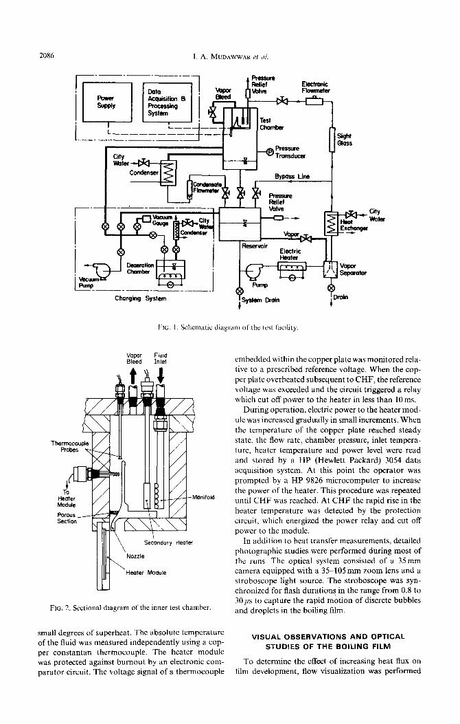
The flow loop utilized in this study was designed to insure high purity circulation of the working fluid (FC-72) over the boiling surface. As shown in Fig. 1, the fluid was boiled inside a deaeration vessel prior to delivery into the primary flow loop. The deaeration vessel consisted of a 3 gallon stainless steel container fitted with four immersion heaters on its bottom sec- tion and a reflux condenser mounted directly above the vessel. Prior to testing, the primary flow loop was evacuated to less than 500pm Hg to remove air and other noncondensible gases. The working fluid was then charged into the main reservoir, where it was stored for subsequent runs. During startup, the fluid was circulated within the primary loop by a stainless steel, magnetically-driven centrifugal pump, while being heated by a temperature-controlled electric heater. The operating pressure within the test chamber was monitored by an absolute pressure transducer, and the fluid flow rate was measured through a turbine flowmeter. A cyclone phase separator located down- stream of the electric heater rejected all entrained vapor back into the reservoir, allowing only liquid to enter the test chamber. The separator eliminated flow rate measurement errors by the turbine flowmeter. A sight glass connected between the phase separator and the flowmeter facilitated visual observation of the fluid upstream of the flowmeter to insure bubble-free flow. The flow rate was controlled by varying the speed of the pump and bypassing some of the fluid into the reservoir. Steady-state pressure and temperature control were achieved by condensing the vapor pro-
duced in the test chamber and routing the condensate back into the reservoir, as well as by heating the fluid in the primary electric heater to balance heat losses from the loop. A secondary heat exchanger located upstream of the test chamber was also used in some runs to achieve subcooled film conditions.
The test chamber, which is shown in Fig. 1, con- sisted of two parts, the inner film injection chamber and the outer enclosure. Both chambers were fab- ricated of G-10 fiberglass and fitted with optical-grade polycarbonate (Zelux-W) windows to facilitate visual access to the boiling film. As shown in Fig. 2, the fluid was introduced into the inner chamber through a stainless manifold in crossflow over a cylindrical cartridge heater. This heater was utilized as a thermal guard against heat losses for saturated film data. The fluid was introduced over the vertical heated module via an adjustable rectangular nozzle. A vapor bleed line was located at the top of the inner chamber to vent any vapor before reaching the nozzle.
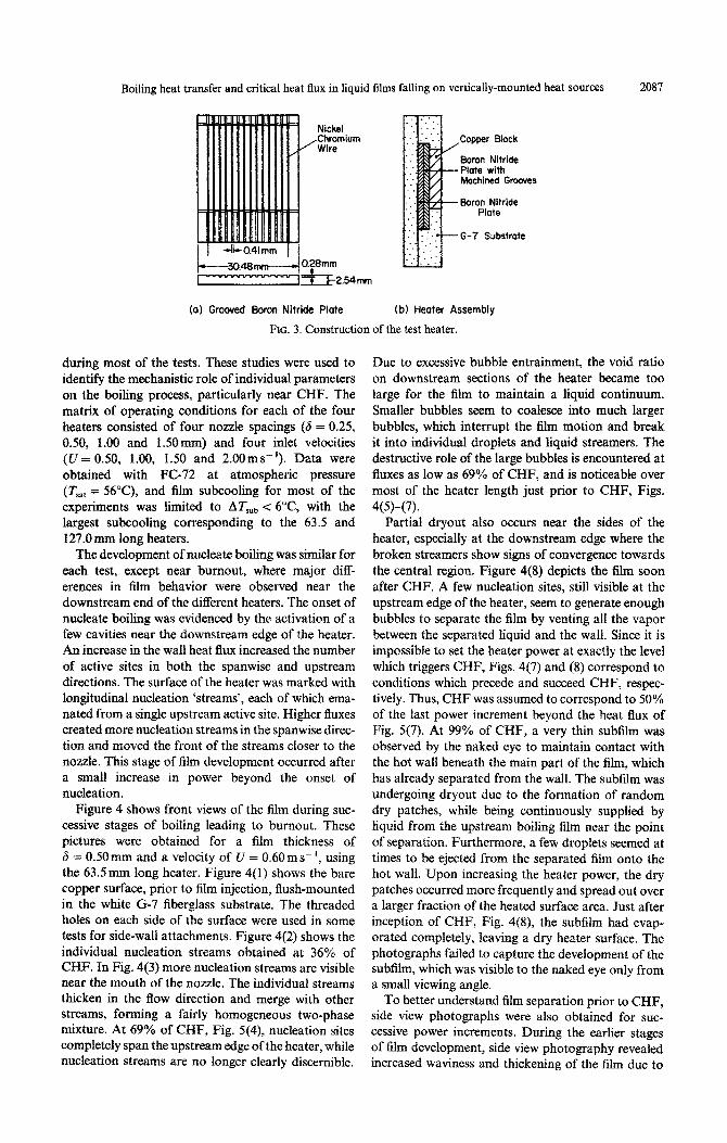
Four different rectangular heater modules were tested to correlate the length effect of CHF. The mod- ules were 25.4mm wide, with lengths of 12.7, 25.4, 63.5 and 127mm. As shown in Fig. 3, each module consisted of three parallel attachments: an oxygen- free copper surface, a heat source, and an insulating substrate. The 5.1 mm thick copper plate provided a thermally conductive path from the heat source to the boiling film. The boiling surface was prepared with ultrafine 600 silicon carbide sandpaper and cleaned before each run with acetone. The heat source consisted of a nickelchromium resistive wire, 0.356mm in diameter, sandwiched between two thermally conducting boron nitride ceramic plates (k=65Wm-’ K- I). Fourteen vertical grooves, 0.28 mm deep and 0.406 mm wide, were machined in the surface of the boron nitride plate adjacent to the copper plate. The wire was placed within the grooves and covered with fine boron nitride powder to mini- mize thermal contact resistances. The G-7 fiberglass insulating substrate insured that most of the heater power was dissipated to the boiling surface and pro- vided for careful alignment and secure mechanical clamping of the module. A two-dimensional numeri- cal analysis of heat transfer within the module revealed that less than 10% of the input power is lost to the G-7 substrate.
The resistive wire was heated by a 3OOV, 9A d.c. Sorensen power supply. The heater voltage drop was measured across the power leads to the nichrome wire, while the current was measured across an external shunt connected in series with the heater. Differential thermocouples were employed to measure the tem- perature of the copper plate. One junction of each chromel-alumel thermocouple (0.125 mm diameter) was embedded within the copper plate 2.54mm away from the boiling surface. The other junction was immersed in the fluid upstream of the nozzle. Thus the temperature of the copper block relative to the fluid temperature was measured accurately, even for
2086 I. A. MUDAWWAR et al.
Charging System
FIG. I. Schematic diagram of the test facility
1. 1 R_&/#-Monifold
POrOUS
Section
Secondary Heater
Heater Module
FIG. 2. Sectional diagram of the inner test chamber.
small degrees of superheat. The absolute temperature of the fluid was measured independently using a cop- per-constantan thermocouple. The heater module was protected against burnout by an electronic com- parator circuit. The voltage signal of a thermocouple
City water
embedded within the copper plate was monitored rela- tive to a prescribed reference voltage. When the cop-
per plate overheated subsequent to CHF, the reference voltage was exceeded and the circuit triggered a relay which cut off power to the heater in less than 10 ms.
During operation, electric power to the heater mod-
ule was increased gradually in small increments. When the temperature of the copper plate reached steady state, the flow rate, chamber pressure, inlet tempera- ture, heater temperature and power level were read and stored by a HP (Hewlett Packard) 3054 data acquisition system. At this point the operator was prompted by a HP 9826 microcomputer to increase
the power of the heater. This procedure was repeated until CHF was reached. At CHF the rapid rise in the heater temperature was detected by the protection circuit, which energized the power relay and cut off power to the module.
In addition to heat transfer measurements, detailed photographic studies were performed during most of the runs. The optical system consisted of a 35mm camera equipped with a 35-105 mm zoom lens and a stroboscope light source. The stroboscope was syn- chronized for flash durations in the range from 0.8 to 30 ps to capture the rapid motion of discrete bubbles and droplets in the boiling film.
VISUAL OBSERVATIONS AND OPTICAL STUDIES OF THE BOILING FILM
To determine the effect of increasing heat flux on film development, flow visualization was performed
Boiling heat transfer and critical heat flux in liquid films falling on vertically-mounted heat sources 2087
Nickel ,Chromium
Wire -Copper Block
Boron Nitride ‘Plate with Machined Grooves
.Eloron Nitride Plate
G-7 Substrate
(al Grooved Baron Nitride Plate (b) Heoter Assembly
FIG. 3. Construction of the test heater.
during most of the tests. These studies were used to identify the mechanistic role of individual parameters on the boiling process, particularly near CHF. The matrix of operating conditions for each of the four
heaters consisted of four nozzle spacings (8 = 0.25, 0.50, 1.00 and 1 SO mm) and four inlet velocities (U = 0.50, 1.00, 1.50 and 2.00 m s- ‘). Data were obtained with FC-72 at atmospheric pressure (Z’8,t = 56”(Z), and film subcooling for most of the experiments was limited to ATsub < 6”C, with the largest subcooling corresponding to the 63.5 and 127.0 mm long heaters.
The development of nucleate boiling was similar for each test, except near burnout, where major diff- erences in film behavior were observed near the downstream end of the different heaters. The onset of nucleate boiling was evidenced by the activation of a few cavities near the downstream edge of the heater. An increase in the wall heat flux increased the number of active sites in both the spanwise and upstream directions. The surface of the heater was marked with longitudinal nucleation ‘streams’, each of which ema- nated from a single upstream active site. Higher fluxes created more nucleation streams in the spanwise direc- tion and moved the front of the streams closer to the nozzle. This stage of film development occurred after a small increase in power beyond the onset of nucleation.
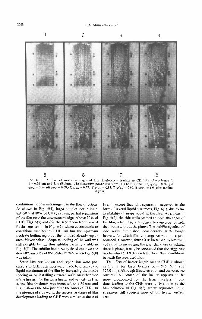
Figure 4 shows front views of the film during suc- cessive stages of boiling leading to burnout. These pictures were obtained for a film thickness of 6 = OSOrnm and a velocity of U = 0.60m s- ‘, using the 63Smm long heater. Figure 4(l) shows the bare copper surface, prior to film injection, flush-mounted in the white G-7 fiberglass substrate. The threaded holes on each side of the surface were used in some tests for side-wall attachments. Figure 4(2) shows the individual nucleation streams obtained at 36% of CHF. In Fig. 4(3) more nucleation streams are visible near the mouth of the nozzle. The individual streams thicken in the flow direction and merge with other streams, forming a fairly homogeneous two-phase mixture. At 69% of CHF, Fig. 5(4), nucleation sites completely span the upstream edge of the heater, while nucleation streams are no longer clearly discernible.
Due to excessive bubble entrainment, the void ratio on downstream sections of the heater became too large for the film to maintain a liquid continuum. Smaller bubbles seem to coalesce into much larger bubbles, which interrupt the film motion and break it into infidel droplets and liquid streamers. The destructive role of the large bubbles is encountered at fluxes as low as 69% of CHF, and is noticeable over most of the heater length just prior to CHF, Figs.
4(5)_(7). Partial dryout also occurs near the sides of the
heater, especially at the downstream edge where the broken streamers show signs of convergence towards the central region. Figure 4(8) depicts the film soon after CHF. A few nucleation sites, still visible at the upstream edge of the heater, seem to generate enough bubbles to separate the film by venting all the vapor between the separated liquid and the wall. Since it is impossible to set the heater power at exactly the level which triggers CHF, Figs. 4(7) and (8) correspond to conditions which precede and succeed CHF, respec- tively. Thus, CHF was assumed to correspond to 50% of the last power increment beyond the heat flux of Fig. 5(7). At 99% of CHF, a very thin subfilm was observed by the naked eye to maintain contact with the hot wall beneath the main part of the film, which has already separated from the wall. The subfilm was undergoing dryout due to the formation of random dry patches, while being continuously supplied by liquid from the upstream boiling film near the point of separation. Furthe~ore, a few droplets seemed at times to be ejected from the separated film onto the hot wall. Upon increasing the heater power, the dry patches occurred more frequently and spread out over a larger fraction of the heated surface area. Just after inception of CHF, Fig. 4(8), the subfilm had evap- orated completely, leaving a dry heater surface. The photographs failed to capture the development of the subfilm, which was visible to the naked eye only from a small viewing angle.
To better understand film separation prior to CHF, side view photographs were also obtained for suc- cessive power increments. During the earlier stages
of film development, side view photography revealed increased waviness and thickening of the film due to
2088 I. A. MLWAWWAK cv ~1.
5 6 7 8 FIG. 4. Front views of successive stages of film development leading to CHF for iI .-- 0.59ms ‘, 6 = 0.50mm and L = 63.5mm. The successive power levels arc: (I) bare surface. (2) q;y, -= 0.36. (3) q/qM = 0.54, (4) q/qM = 0.69, (5) q/qM = 0.77. (6) q/qM = 0.88, (7) yjqu = 0.99. (8) qjqH = I .O (after subfilm
dryout).
continuous bubble entrainment in the flow direction.
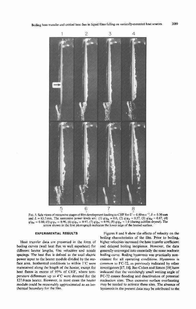
As shown in Fig. 5(4), iarge bubbles occur inter- mittently at 80% of CHF, causing partial separation of the film near the downstream edge. Above 90% of CHF, Figs. 5(S) and (6) the separation front moved further upstream. In Fig. 5(7), which corresponds to conditions just before CHF, all but the upstream nucleate boiling region of the film had already separ- ated. Nevertheless, adequate cooling of the wall was still possible by the thin subfilm partially visible in Fig. 5(7). The subfilm had already dried out over the downstream 30% ofthe heater surface when Fig. 5(S) was taken.
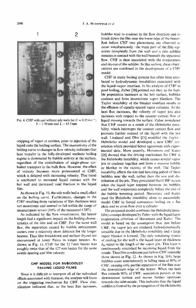
Since film breakdown and separation were prc- cursors to CHF, attempts were made to preserve the liquid continuum of the film by increasing the nozzle spacing or by installing elevated walls on either side of the heater. For the same heater and velocity as Fig. 4, the film thickness was increased to 1 SO mm and Fig. 6 shows the film just after the onset of CHF. In the absence of side walls, the successive stages of film development leading to CHF were similar to those of
Fig. 4, except that film separation occurred in the form of several liquid streamers, Fig. 6(l), due to the availability of more liquid in the Elm. As shown in
Fig. 6(2), the side walls seemed to hold the edges of the film, which had a tendency to converge towards the middle without the plates. The stabilizing effect ot side waits diminished considerably with longer heaters, For which film convergence was more pro- nounced. However, since CHF increased by less than 10% due to increasing the film thickness or adding the side piates. it may be concluded that the triggering mechanism for CHF is related to surface conditions beneath the separated film.
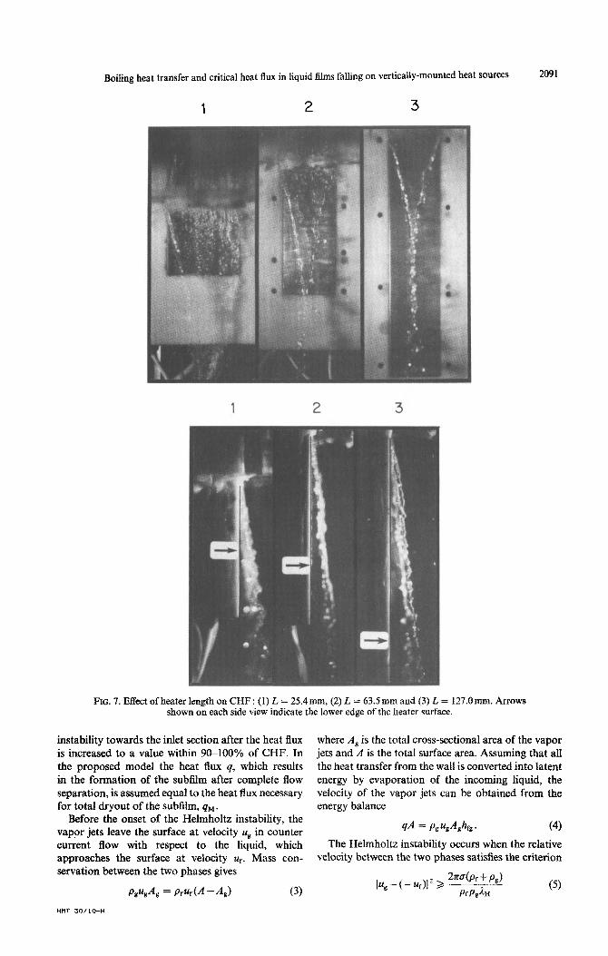
The effect of heater length on the CHF is shown in Fig. 7 for three heaters (2, = 24.5, 63.5 and 127.0 mm). Although film separation and convergence towards the center of the heater appears to be more pronounced for the larger heaters. condi- tions leading to the CHF were fairly similar to the film behavior of Fig. 4(7), where separated liquid streamers still covered most of the heater surface area.
Boiling heat transfer and critical heat flux in liquid films falling on vertically-mounted heat sources
FIG. 5. Si and L= 9/4M = 0
EXPERIMENTAL RESULTS
Heat transfer data are presented in the form of boiling curves (wall heat flux vs wall superheat) for different heater lengths, film velocities and nozzle spacings. The heat flux is defined as the total electric power input to the heater module divided by the sur- face area. Isothermal conditions to within 1°C were maintained along the length of the heater, except for heat fluxes in excess of 95% of CHF, where tem- perature differences up to 4°C were detected for the 127.Omm heater. However, in most cases the heater module could be reasonably approximated as an iso- thermal boundary for the film.
6 = 0.50 fM = 0.67 dryout).
2.
2089
mm
(4) ‘The
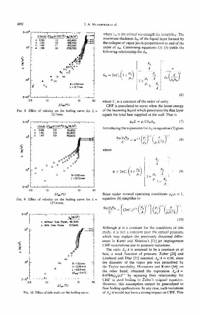
Figures 8 and 9 show the effects of velocity on the boiling characteristics of the film. Prior to boiling, higher velocities increased the heat transfer coefficient and delayed boiling incipience. However, the data generally converged into essentially the same nucleate boiling curve. Boiling hysteresis was practically non- existent for all operating conditions. Hysteresis is common to FC-72, as previously indicated by other investigators [17,18]. Bar-Cohen and Simon [19] have indicated that the vanishingly small wetting angle of FC-72 causes flooding and deactivation of potential nucleation sites. Thus excessive surface overheating may be needed to activate these sites. The absence of hysteresis in the present data may be attributed to the
2090 1. A. MUDAWWAR et ul.
FIG. 6. CHF with and without side walls for U = 0.55 ms-I, 6=1.50mmandL=63.5mm
trapping of vapor in cavities, prior to injection of the liquid onto the boiling surface. The insensitivity of the
boiling curve to changes in flow velocity indicates that heat transfer in the fully-developed nucleate boiling regime is dominated by bubble activity at the surface, regardless of the contribution of single-phase tur- bulent transport in the bulk flow. However, the effect
of velocity becomes more pronounced at CHF, which is delayed with increasing velocity. This trend is attributed to increased liquid contact with the
hot wall and decreased void fraction in the liquid film.
As shown in Fig. 10, the side walls had a small effect
on the boiling curve. Furthermore, changes in the CHF resulting from variations of film thickness were not monotonic and seemed to fall within the range of measurement errors (10% of the measured CHF).
As indicated by the flow visualization, the heater
length had a significant impact on the boiling charac- teristics of the film and on CHF. For the same wall flux, the separation caused by bubble entrainment occurs over a relatively short distance for the longer heaters. Thus film breakdown and surface dryout are encountered at lower fluxes in longer heaters. AS shown in Fig. 11, CHF for the 12.7mm heater was roughly twice that of the 127 mm heater for the same nozzle spacing and film velocity.
CHF MODEL FOR SUBCOOLED
FALLING LIQUID FILMS
Since it is difficult to interpret all of the individual effects associated with burnout, the analysis will focus on the triggering mechanism for CHF. Flow visu- alization indicated that, as the heat flux increases,
bubbles tend to coalesce in the flow direction and to break down the film near the lower edge of the heater, Just before CHF two phenomena arc observed to occur simultaneously : the main part of the film scp- arates completely from the wall and a thin subfilm remains in contact with the wall beneath the separated flow. CHF is then associated with the evaporation
and dryout of the subfilm. In this section, these obscr- vations are combined in the development of a CHl model.
CHF in many boiling systems has often been attri- buted to hydrodynamic instabilities associated with the liquid-vapor interface. In his analysis of CHF in
pool boiling, Zuber [20] pointed out that, as the bub- ble population increases at the hot surface, bubbles coalesce and form intermittent vapor blankets. The Taylor instability of the blanket interface results in the effusion of equally-spaced vapor columns. .4s the heat flux increases, the velocity of vapor jets also increases with respect to the counter current flow of
liquid moving towards the surface. Zuber postulated that CHF occurs as a result of the Helmholtz insta-
bility, which interrupts the counter current flow and prevents further contact of the liquid with the hot wall. Lienhard and Dhir [21] modified the Taylor
Helmholtz model and developed a new CHP cor- relation which provided better agreement with cxper-
imental data. More recently, Haramura and Katto [16] showed that the driving mechanism for CHF is the Helmholtz instability, which causes several vapor jets to coalesce together and form a massive bubble or blanket in the vicinity of the wall. The Taylor instability affects the size and hovering period of these bubbles near the wall, rather than the size and dis- tribution of the jets. They postulated that CHF OCCUI N when the liquid layer trapped between the bubbles and the wall evaporates completely before the end of the bubble hovering period, Haramura and Katto used the Helmholtz instability alone to successfully model CHF in forced convection boiling on a flat plate and in cross flow over a cylinder.
The proposed model combines the Helmholtz msta- bility concept developed by Zuber with the liquid laye~ evaporation criterion of Haramura and Katto. The model is based on the assumption that. just before CHF. the vapor jets are rendered hydrodynamically unstable due to the Helmholtz instability and a large vapor blanket is formed. The only remaining source of cooling for the wall is the liquid layer of thickness 6, equal to the length of the vapor jets. This iayer is continuously nourished by incoming liquid from the nozzle. Thus film conditions just before CHF resemble those shown in Fig. 12. As shown in Fig. 5(d), large bubbles occur intermittently in falling films at 80% of CHF, causing only partial separation of the film near the downstream edge of the heater. When the heat flux exceeds 90% of CHF, separation persists at the downstream section and moves further upstream towards the inlet nozzle. This indicates that the liquid subfilm is formed by the propagation of the Helmholtz
Boiling heat transfer and critical heat flux in liquid films falling on vertically-mounted heat sources 2091
FIG. 7. Effect of heater length on CHF : (1) L = 25.4 mm, (2) L = 63.5 mm and (3) t = 127.0 mm. Arrows shown on each side view indicate the lower edge of the heater surface.
instability towards the inlet section after the heat flux where A, is the total cross-sectional area of the vapor is increased to a value within 9&100% of CHF. In jets and A is the total surface area. Assuming that all the proposed model the heat flux q, which results the heat transfer from the wall is converted into latent in the formation of the subfilm after complete flow energy by evaporation of the incoming liquid, the separation, is assumed equal to the heat flux necessary velocity of the vapor jets can be obtained from the for total dryout of the subfilm, qM . energy balance
Before the onset of the Helmholtz instability, the vapor jets leave the surface at velocity a8 in counter current flow with respect to the liquid, which approaches the surface at velocity ur. Mass con- servation between the two phases gives
qA = Pg~g~g~fg. (4)
The Helmholtz instability occurs when the relative velocity between the two phases satisfies the criterion
(5)
2092 1. A. MUDAWWAR et al.
3x10S r
Id I c
“E 3 - i CT I
0.3 1.0 IO 30
AT,tPC)
FIG. 8. Effect of velocity on the boiling curve for L = 12.7mm.
_ U(m,+) AT&a+ CHF(OC) q,JW/m’,
0 0.99 5.5 81,800 Is I.46 5.9 62,900
lOs 0 1.97 5.9 95.600
0.3 1.0 IO 30
AT, (“‘3
FIG. 9. Effect of velocity on the boiling curve for L = 127.0mm.
3.18
o Without Side Plates 92,500
A With Side Plates
a0
IO’ b 8=1.5Omm
B U = 0.55 m/s
L = 63.5mm
0 ATmb=3.4'C
I 0.3 1.0 IO x)
AT,.,, (“Cl
FIG. 10. Effect of side walls on the boiling curve
where i,, is the critical wavelength for instability. The maximum thickness 6, of the liquid layer formed by the collapse of vapor jets is proportional to and of the order of 1,. Combining equations Q---(5) yields the following relationship for 6,
ff
0s 4 i (-----I es
(f-7
where C:, is a constant of the order of unity.
CHF is postulated to occur when the latent energy of the incoming liquid which penetrates the thin layer equals the total heat supplied at the wall. That is
q,L = ~rU&,h,
Introducing the expression for 6, in equation (7) gives
where
(8)
(9
Since under normal operating conditions p,/p, << I, equation (8) simplifies to
Although $ is a constant for the conditions of this study, it is not a constant near the critical pressure, which may explain the previously discussed differ-
ences in Katto and Shimizu’s [II] jet impingement CHF correlations due to pressure variations.
The ratio A,/A is assumed to be a constant or at best, a weak function of pressure. Zuber [20] and Lienhard and Dhir [21] assumed AJA = x/16, since the diameter of the vapor jets was prescribed by the Taylor instability. Haramura and Katto [16], on the other hand, obtained the expression ,4,/A = 0.0584(p,/pf)o * by equating their relationship for CHF in pool boiling to Zuber’s original equation. However, this assumption cannot be generalized to flow boiling applications. In any case, such variations of A,/A would not have a strong impact on CHF. This
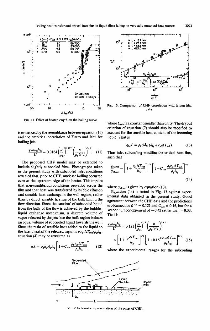
Boiling heat transfer and critical heat flux in liquid films falling on vertically-mounted heat sources 2093
L(mm)
12.7 25.4 63.5 127.0
Id i o 0 A : A” .
0 . 0 8=0.5Omm
. U 0.99 1.03 = - rnjk
FIG. 11. Effect of heater length on the boiling curve.
is evidenced by the resemblance between equation (10) and the empirical correlation of Katto and Ishii for boiling jets
(11)
The proposed CHF model may be extended to include slightly subcooled films. Photographs taken in the present study with subcooled inlet conditions revealed that, prior to CHF, nucleate boiling occurred even at the upstream edge of the heater. This implies that non-equilibrium conditions prevailed across the film and that heat was transferred by bubble effusion and sensible heat exchange in the wall region, rather than by direct sensible heating of the bulk film in the flow direction. Since the ‘suction’ of subcooled liquid from the bulk of the flow is achieved by the bubble- liquid exchange mechanism, a discrete volume of vapor released by the jets into the bulk region induces an equal volume of subcooled liquid towards the wall. Since the ratio of sensible heat added to the liquid to the latent heat of the released vapor is p+AT,,,/p,h,, equation (4) may be rewritten as
Setmroted Fldw
\
0 L= 127mm 0 I_= 25.4mm A L=63.5mm 0 L=l27.0mm
-e P$L
FIG. 13. Comparison of CHF correlation with falling film data.
where C,, is a constant smaller than unity. The dryout criterion of equation (7) should also be modified to account for the sensible heat content of the incoming liquid. That is
q& = iN&, (h, + c&7’&. (13)
Thus inlet subcooling modifies the critical heat flux, such that
(14)
where qM,=* is given by equation (10). Equation (14) is tested in Fig. 13 against exper-
imental data obtained in the present study. Good agreement between the CHF data and the predictions is obtained for $I” = 0.121 and Csub = 0.16, but for a Weber number exponent of - 0.42 rather than -0.33. That is
1 2’3 WI where the experimental ranges for the subcooling
FIG. 12. Schematic representation of the onset of CHF.
2094 I. A. MUDAWWAR et al.
terms cpfATs,,/h,, and (pJp,)cpfATs,,/h,, are 0.00676-- Acknowledgement-Support by the Data Systems Division 0.129 and 0.808-11.53, respectively. of IBM is gratefully acknowledged.
Equation (15) correlates CHF data with a mean
accuracy of 18.2% and is recommended for the boiling of vertical liquid films. The difference between the Weber number dependence of the CHF model and that of the experimental correlation may be due to
secondary effects, such as partial dryout near the sides and the downstream edge of the heated surface, especially for the longer heaters. The predicted Weber number exponent is identical to that of Katto and Ishii’s correlation, equation (1 l), for high speed wall
jets. Their study was conducted with shorter heaters and much higher velocities, which helped prevent par- tial dryout.
REFERENCES
Since the present experiments were conducted at pressures close to atmospheric, the ratio pg/pf is fixed (approximately 0.0083) and the data cannot be used to verify the exponent of 213 which appears with the
density ratio in equation (15). From previous studies of CHF in thin parallel liquid jets [ 151, which encom- passed density ratios between 0.0006 and 0.005, the exponent of pJp% was determined empirically to be 0.81 or 0.867 (see equation (11)). If these exponents were used instead of 2/3 in equation (15), the constant coefficient of the present correlation becomes 0.061 or
0.046, respectively. However, from experiments on radial films formed by jet impingement [15] which
encompassed the range of density ratios from 0.006 to 0.04, an empirical exponent of 0.645 was deter- mined for pf/pg This result is in good agreement with
the value predicted by the model of this study.
CONCLUSIONS
(1) Nucleate boiling in vertical liquid films causes significant longitudinal variations in film behavior. Vigorous boiling destroys the liquid continuum of
the film near the downstream edge of the heater and results in the formation of individual liquid streamers
and droplets. (2) Film breakdown and separation occur prior to
CHF. The difference in film behavior for conditions just before and after CHF is the dryout of a thin
subfilm beneath the separated liquid. (3) The film thickness and side walls alter the break-
down pattern of the separated liquid without affecting wall conditions beneath the film. Thus CHF is approximately independent of these two effects.
(4) Higher CHF was achieved with higher film speeds and shorter heaters. Higher velocities also increased the convective heat transfer coefficient prior to boiling and delayed boiling incipiences.
(5) CHF in flowing liquid films is triggered by the Helmholtz instability, which separates the main part of the film leaving a thin liquid layer in contact with the wall. Burnout occurs when the latent heat of the liquid entering this layer at the nozzle is less than the total heater power. A model based on these mech- anisms was shown to successfully correlate CHF data
1.
2.
3.
4.
5.
6.
7.
8.
9.
10.
11.
12
13
14
I5
16
17.
18.
19.
20.
21
R. Mesler, Nucleate boiling in thin liquid film. In Boiling Phenomena (Edited by S. Van Stralen and R. Cole), Vol.
2, pp. 8 13-S 19. Hemisphere, Washington (1976). Y. Hsu and R. Graham, Transport Processes in Boiling and Two-phase Systems, p. 59. McGraw-Hill, New York (1976). M. G. Cooper, The microlayer and bubble growth in nucleate pool boiling, Int. J. Heat Ma.ss Transfer 12, 915-933 (1969). H. J. Van Ouwerkerk, The rapid growth of a bapour bubble at a liquid-solid interface, ht. J Heat Ma.u Transfer 14, 1415-1431 (1971). T. Ueda, M. Inoue and S. Nagatome, Critical heat flux and droplet entrainment rate & boiling of falling liquid films. In!. J. Heat Mass Transfb 24. 1257.-1266 (1981). S. Toda and H. Uchida, Studiof liquid film cooling with evaporation and boiling, Trans. Jap. Sac. Mrch. Eng,:c 38, 1830-1848 (1972). Y. Katto and M. Kunishiro, Study of the mechanism of burn-out in boiling systems of high burn-out heat flux. Bull. Jap. Sot. Mech. Engrs 16, 135771366 (1973). Y. Katto and M. Monde, Study of mechanism of burn- out in high heat-flux boiling system with an impinging jet, Proc. 5th Int. Heat Tramfey Conf.. Tokyo. Japan. Vol. 4, pp. 245-249 (1974). Y. Katto and K. Ishii, Burnout in a high heat flux boiling system with a forced supply of liquid through a plane jet, Proc. 6th Int. Heat Transfer Cor$, Toronto, Canada. Vol. 1, pp. 435440 (1978). M. Monde and Y. Katto, Burnout in high heat-flux boiling system with an impinging jet. Int. J. Heat Mass Transfer 21,295-305 (1978). Y. Katto and M. Shimizu, Upper limit of CHF in the saturated forced convection boiling on a heated disk with a small impinging jet, J. Hear Transfer 101, 265 269 (1979). R. P. Baines, M. A. El-Masri and W. M. Rohsenow, Critical heat flux in flowing liquid films, In/. J. Heat Mass Transfer 21, 1623-1629 (1984). J. H. Lienhard and R. Eichhorn, On predicting boihng burnout for heaters cooled by liquid jets. Int. .I. Heaz Mass Transfer 22, 774-776 (1979). J. H. Lienhard and Md. M. Hasan, On predicting boiling burnout with the mechanical energy stability criterion. J. Heat Transfer 101,27&279 (1979). Y. Katto. Critical heat flux, Adu. Heat Transfer 17, 1 64 (1985). Y, Haramura and Y. Katto, A new hydrodynamic model of critical heat flux aoolicable widelv to both pool and forced convection boiling on submerged bodies in salu- rated liquids, Int. J. Heat Mass Transfer 26, 389-399 (1983). A. E. Bergles and M. C. Chyu, Characteristics of nucleate pool boiling from porous metallic coatings, J. Heat Transfer 104,279.-285 (1982). P. J. Marto and V. J. Lepere, Pool boiling heat transter from enhanced surfaces to dielectric fluids, .I Heai Transfer 104,292-299 (1982). A. Bar-Cohen and T. W. Simon, Wall superheat excur- sions in the boiling incipience of dielectric fluids. In Heat Transfer in Electronic Equipment (Edited by .4. Bar- Cohen), HTD-Vol. 57. pp. 83-94 (I 986). N. Zuber, Hydrodynamic aspects of boiling heat trans- fer, AEC Report No. AECU- (1959). J. H. Lienhard and V. K. Dhir, Hydrodynamic pre- dictions of peak pool-boiling heat fluxes from finite bodies, J. Heat Tramfer 95, 152 I58 (1973)
Boiling heat transfer and critical heat flux in liquid tilms falling on vertically-mounted heat sources 2095
TRANSFERT THERMIQUE PAR EBULLITION ET FLUX THERMIQUE CRITIQUE DANS LES FILMS LIQUIDES TOMBANT SUR DES SOURCES MONTEES
VERTICALEMENT
R&sum&-Des mesures de transfert thermique par tbullition sont obtenus avec un fluorocarbone inerte
(FC-72) inject& en film liquide sur une paroi verticale chautfee. Une visualisation montre qu’une Bbullition intense avant l’assechement rompt la continuitb du film, causant ainsi la separation de la plupart du tibn et laissant un sous-ti liquide mince qui maintient le contact avec la paroi. Le flux thermique critique
(CHF) est accompagnb par l’as&chement du sous-film apr&s separation totale du liquide pres du bord du chauffoir. Un CHF plus 61ev6 est obtenu en augmentant la vitesse du Bhn ou en utilisant un chaulToir plus court. Des don&es experimentales se regroupent bien avec les predictions d’un modele de CHF base sur
l’instabilid de Hehnholtz et la sechage du sous-film.
WARMEUBERGANG BEIM SIEDEN UND KRITISCHE WARMESTROMDICHTE IN FLUSSIGEN FALLFILMEN AN SENKRECHTEN HEIZFLACHEN
Zmammenfass~g-Es wurden Messungen zum Wiirmeiibergang beim Sieden eines triigen, iiber einer vertikalen beheizten Wand verteilten Fluorcarbon (FC-72)-Fltissigkeitsfihns durchgefiihrt. Die Sicht- barmachung der Strdmung zeigte, dal3 lebhaftes Sieden vor dem “burnout” den zusammenhiingenden Fliissigkeitstilm unterbrach turd den griilten Teil des Films veranlaflte, sich von der beheizten Wand zu trennen. Dabei bleibt eine diinne Fliissigkeitsunterschicht mit Wandkontakt zuriick. Die kritische Wiirmestromdichte (CHF) ist verbunden mit dem Austrocknen der Unterschicht nach der vollstandigen Verdrgngung der Fliissigkeit in der N&e der Oberkante der HeizlIache. Ein hiiheres CHF wurde durch Erhijhung der Filmgeschwindigkeit oder durch eine kilrzere Hetiiiche erreicht. Die experimentellen Daten werden mit einem CHF-Modell, das aufder Hehnholtz-Instabilitiit und Unterschichtaustrocknung beruht,
recht gut wiedergegeben.
TEIIJIOOBMEH IIPH KMHEHMH M KPM3HC KAIIEHHX B I-IJ-IEHKE XMAKOCTM, CTEKAIolqEH HO BEPTMKAJIbHOMY TEl-IJIOBbI~EJI~KXIIEMY 3JIEMEHTY
Afarora~w-Hposenetibt n3Mepetiun rennoo6t.%eua npn nneuovuoM xunenuu uuepmoro Qropoyrne- pOna FC-72 Ha BepTHKUbHO HarpeBaeMOZi CTeHKe. BH3yaJIH3aUHa nOTOKa nOKa3aJla,'iTO HHTeHCHBHOe
KHIKTHHC, II~~“I‘XTB,‘,O”&X KP&iSiC)‘, Hap,‘WaJIO CtlJlOmHOCTb XHLlKOCTH W Bbt3btBUO OTAe,teHHe
6onbmeii KacTn nneHKH, TaK STO Ha ee nosepxHocra 0cTasancn ~01iKHi4 noacnok. IIpw nocrmiceHHn
KpHTHWCKOrO Ten,tOBOrO nOTOKa HC'te3aJI H 3TOT nO,WtOfi. YBCJlHW.HHe KpHTHWCKOrO Ten,,OBOrO
noToKa6btnonony~eHo3ac~eTnosbtmeHHnc~opocTncreKaHrin nneHKHHnunpHMeHeHHn6onee KOPOT- KOrO HarpeBaTeJta. Haiineuo, XOpOmeeCOOTBeTCTBHe MeWty 3KCnepHMeHTaJTbHbtMH AaHHUMH H p3yJlb-
TaTaMHpaC~eTOB,OCHOBaHHbtXHaMO~eJIHHeyCTOfi'iHBoCTH l-eJtbMrOJIbuanpHBbtCbrXaHHunJteHKEi.