Blinkduino User manual - eicaslab.com · The professional software suite for automatic control...
21
The professional software suite for automatic control design and forecasting Blinkduino User manual Version 1.0 www.eicaslab.com
Transcript of Blinkduino User manual - eicaslab.com · The professional software suite for automatic control...
The professional software suite
for automatic control design and forecasting
Blinkduino
User manual
Version 1.0
www.eicaslab.com

How to contact EICAS Automazione S.p.A.
www.eicas.it web site
[email protected] mail support
+39 011 5623798 phone
+39 011 5623088
+39 011 4360679 fax
Via Vincenzo Vela, 27 address
10128 Torino
Italy
Further information are available at EICASLAB web site www.eicaslab.com
Blinkduino 1.0 User manual
COPYRIGHT 2007 - 2016 by EICAS Automazione S.p.A.
The software described in this document is furnished under a license agreement. The software may be used or
copied only under the terms of the license agreement. No part of this manual may be photocopied or reproduced
in any form without prior written consent from EICAS Automazione S.p.A.
Printing History: May 2016, first printing for Blinkduino 1.0 User manual

B l i n k d u i n o U s e r m a n u a l
1
Preface
This document is the user manual of the Blinkduino demo application of EICASLAB, indicated as “the
demo” in the rest of the document. This manual contains a specific information on the demo and a F.A.Q.
list, but the details on the full version of EICASLAB, its features and functions are available apart in its main
documentation (EICASLAB User Manual) included also in the demo installation directory.
If you have more questions or need further assistance, you can contact the EICASLAB support team by email
B l i n k d u i n o U s e r m a n u a l
2
Contents
Preface ........................................................................................................... 1
Contents ........................................................................................................ 2
Overview ....................................................................................................... 3
Key Features ............................................................................................................... 3
Operative modes and tools......................................................................................... 3
Requirements ................................................................................................ 4
Requirements for the PC ............................................................................................ 4
Requirements for the target ........................................................................................ 5
Installation .................................................................................................... 6
Download ................................................................................................................... 6
Install .......................................................................................................................... 6
Run the MASTER tool .............................................................................................. 7
Open the project ......................................................................................................... 7
Automatic Code Generation ....................................................................... 9
Target modules ........................................................................................................... 9
SIMBUILDER tool.................................................................................................... 9
ACG, compile and upload ....................................................................................... 12
Default and user blinking ......................................................................................... 15
Frequently Asked Questions ..................................................................... 18
Why do I cannot see the LED blinking? .................................................................. 18
Why does compilation fails? .................................................................................... 18
Why does programming fails? .................................................................................. 18

B l i n k d u i n o U s e r m a n u a l
3
Overview
The Blinkduino demo was developed to allow the users to test the “ACG for target” feature of EICASLAB
with a popular Arduino® external hardware target, or a compatible device.
Key Features
The demo highlights the following key features of EICASLAB. For more information about them, please visit
the Key Feature pages on the EICASLAB website:
real-time scheduling;
automatic code generation;
Operative modes and tools
The following table summarises the EICASLAB tools used in the demo. More information are available on the
pages How can EICASLAB help you and Tools overview of the software suite website.
Operative mode Tools
Target MASTER, SIMBUILDER
The next sections of the user manual provide details on functions and settings specific of the demo, which
are a demonstrative subset of the EICASLAB software suite features.

B l i n k d u i n o U s e r m a n u a l
4
Requirements
The demo requires two hardware elements:
a PC where to install and run the EICASLAB demo software
an external microcontroller board to run the automatically generated code for a simple “blink a
LED” demonstrative application.
This section describes the hardware and software requirements for the PC and the board. Some common
issues are described in the F.A.Q. section at the end of the document, but if further information or help are
needed, please write to [email protected].
Type Requirement
Hardware PC
Microcontroller board
Software EICASLAB suite
EICASLAB projects
Requirements for the PC
The demo requires a laptop or desktop PC with the following minimum features. There are two versions of
the demo for Windows and Linux operating systems, software requirements depend on that.
Hardware
Dual core CPU
2 GB of RAM
1 GB of disk space
USB-to-serial interface (5V UART)
Windows version software requirements
Windows XP, Vista, 7, 8 or 10 operating systems
WinAVR toolchain (https://sourceforge.net/projects/winavr/files) to cross-compile for the hardware target.
Linux version software requirements
GNU/Linux operative system
avr-gcc and avrdude toolchain to cross-compile for the hardware target. These packages can be

B l i n k d u i n o U s e r m a n u a l
5
found on your Linux distribution repositories: you can use the graphical software update manager
installed in your Linux distribution or use the package manager commands like yum, dnf, apt-get.
Requirements for the target
The Blinkduino application is designed to be run on external hardware target of Arduino®/Genuino™
family of open hardware prototyping boards (www.arduino.cc, www.arduino.org), for example:
Arduino Uno
Arduino Ethernet
Arduino Mini
or a compatible device mounting an AVR microcontroller. Board models without a built-in LED, requires a
LED connected externally to a pin.

B l i n k d u i n o U s e r m a n u a l
6
Installation
After checking the system requirements, the user has to download and install the software, then the starting
point of the demo execution is running the MASTER tool of EICASLAB, as described in the following
paragraphs.
Download
The download link for the demo installer is on the EICASLAB website.
Moreover, in the page of the demo, the user can download all the documentation associated to the demo.
Install
To install the demo, first extract the demo installer archive and then run the Install executable1. The user has
to agree to the license terms and optionally edit the install settings as shown by the installer program windows
(installation directory and other preferences).
1 In order to run the Install executable in Linux OS, open a terminal in the EICASLAB installation folder containing the Install executable and type ./Install followed by <Enter> key.

B l i n k d u i n o U s e r m a n u a l
7
Run the MASTER tool
The entry point to work with EICASLAB software suite is the MASTER tool, which manages the whole
projects and the other tools of the suite: therefore the first step to run the demo is to launch it from the
desktop link or from the installation directory.
Open the project
In the top menu of the MASTER tool window, select the menu DEMO and you can see the menu item of
the project included in the demo: blinkduino, providing an illustrative example of Automatic Code
Generation.
Note
It is recommended to start with this project to become familiar with the ACG for target of EICASLAB and its Target operative mode, then try the more articulated RT-PC and RT-emb

B l i n k d u i n o U s e r m a n u a l
8
demos.
To proceed, click on the project item, and the SIMBUILDER will pop up showing the graphical system
layout of the demo. Next sections help the user to cross step-by-step all the features of EICASLAB available
within this demo.

B l i n k d u i n o U s e r m a n u a l
9
Automatic Code Generation
The demo is designed to highlight the Automatic Code Generation (ACG) for external target, that is the
EICASLAB key feature of Target operative mode: the ACG allows the control designer to avoid porting the
application software to the target hardware architecture and developing its basic software (e.g. the real-time
scheduler, the I/O interfaces, etcetera) because they are automatically created and exported in remote by
EICASLAB.
This section of the user manual provides details on functions and settings specific of the ACG for the
Arduino target of the Blinkduino demo project. More general information about the Target operative mode
of EICASLAB are available in the online documentation and its full user manual.
Target modules
The Automatic Code Generation for target outputs a real-time application which is made by two parts: the
Application Sofware (AS) and the Basic Software (BS). The former includes the control algorithms, whereas
the latter includes the real-time scheduler, the I/O interfaces and other support components.
Among the differences between AS and BS, please note that the BS is architecture-dependent, so EICASLAB has a
dedicated target module to generate code for each different architecture: a target module provides ACG support
for a target family (that is set of similar target types) allowing the EICASLAB user to generate code for some
hardware.
The demo is based on the EICASLAB Target Module for Arduino boards, which allows to generate code for
a family of Arduino-compatible boards including the following boards:
Arduino Uno
Arduino Ethernet
Arduino Mini
For example, the default target in the demo layout is of type “Arduino Uno” compatible and its name is
simply “myBoard”. The following section about the SIMBUILDER tool explains how it is used to configure
“myBoard” in order to automatically generate the firmware for the board.
SIMBUILDER tool
The SIMBUILDER is the tool to create, edit and configure the system layout, both using graphical blocks
and parameter windows. The user can explore the layout double clicking on its elements.

B l i n k d u i n o U s e r m a n u a l
10
The overall system layout of the demo is very simple: it contains no Plant or Mission Area, there is only a
Processor block assigned to “myBoard” target.
Target configuration
Once a processor of the system layout of an EICASLAB project is assigned to a target, the user has to
configure it in order to let ACG feature output a working real-time program to be run by the hardware target.
In general, the configuration of a target starts from default values and should be checked by the user because
it depends on both host and target system configuration. In the case of this demo, the default settings are
suitable for most systems, but we suggest to read the next paragraphs to understand them deeply.
Target parameters. The target parameters are available from the system layout (right click on the graphical
target processor block > TARGET > Configure > Settings) or from the Physical view of the Global data
window (SIMBUILDER menu > Global data > Open global data window).
The target parameters are associated to whole device configuration and the automatic exportation of the
program. The parameters of the demo are shown in the following screenshot.

B l i n k d u i n o U s e r m a n u a l
11
Note
The port path could be different from the default: it depends on the operating system driver for the USB-to-serial device. Typically it is “/dev/ttyACM0” or “/dev/ttyUSB0”, but the “0” could be replaced by an other digit if more USB devices are connected to the PC.
In Windows operating system the serial port should be of type "COM<X>". You can discover it from Hardware Management utility available in Windows OS. Replace <X> with the right identifier shown in the Hardware Management utility.
Interface parameters. The inner processor layout of EICASLAB is shown double-clicking the Processor
block (blue). On its turn, it includes Control blocks (red) and Interface blocks (white), which represent
respectively processing and interfacing activities to be executed. Each block, finally, includes user code and
parameters. In the case of the Blinkduino demo, there are only two blocks in the Processor1 (P1): they are
C1P1 (Control1P1) and Out1P1 (Output Interface1P1).
The Control1P1 control block contains the simple routine which toggles the binary value of a variable (yc1).
Thinking to a more general control design workflow, suppose that such an algorithm description was
previously written in past design phases, typically Modelling and Like Real-time Simulation operative mode.
On the other hand, the Out1P1 interface block represents the digital output connected to the LED to be
blinked on the board. Each target type has its own set of available interfaces (e.g. GPIO, PWM, SPI, I2C,
RS232, RS485, CANbus, etc.) depending on the hardware features.
B l i n k d u i n o U s e r m a n u a l
12
The Digital Interface of the demo has a set of parameters to define the hardware pins to be controlled
(lowest pin, number of pin), their default state and the output mode.
Note
If the hardware board to be programmed has a LED connected to a different pin than the default one, remember to change the “lowest pin” parameter to the correct value.
For example, the Arduino Uno board has its built-in LED on the D13 pin whereas the Arduino Ethernet board has its one on the D9. See paragraph “User LED” for further details.
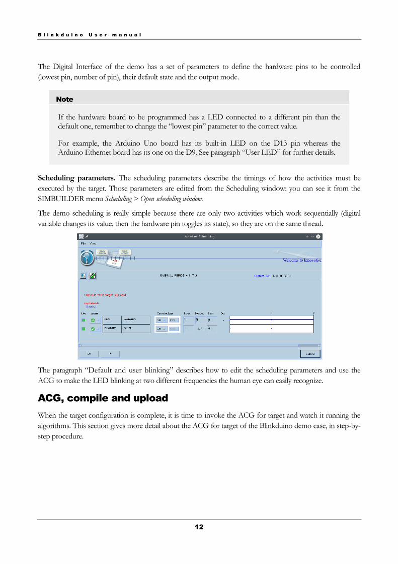
Scheduling parameters. The scheduling parameters describe the timings of how the activities must be
executed by the target. Those parameters are edited from the Scheduling window: you can see it from the
SIMBUILDER menu Scheduling > Open scheduling window.
The demo scheduling is really simple because there are only two activities which work sequentially (digital
variable changes its value, then the hardware pin toggles its state), so they are on the same thread.
The paragraph “Default and user blinking” describes how to edit the scheduling parameters and use the
ACG to make the LED blinking at two different frequencies the human eye can easily recognize.
ACG, compile and upload
When the target configuration is complete, it is time to invoke the ACG for target and watch it running the
algorithms. This section gives more detail about the ACG for target of the Blinkduino demo case, in step-by-
step procedure.

B l i n k d u i n o U s e r m a n u a l
13
Note
The ACG procedure depends on system configuration external to EICASLAB, so issues could
arise from misconfiguration or other reasons. In case of errors, please check the F.A.Q. section
at the end of the document or contact us ([email protected]).
ACG AS+BS
When the configuration is completed, you can create, build and export the blinking program to the
external board: open the Global Data window from the SIMBUILDER top menu Global data > Open
global data and switch to the Physical view. Then select the target item labeled “myBoard” within the
tree.
In the Current selection tab, click on the ACG AS+BS button to invoke the Automatic Code Generation for
the target. You can specify a name to it, otherwise the default name is a composition of current date and
time.

B l i n k d u i n o U s e r m a n u a l
14
The initialization of parameter and state values for devices without a file system is usually from code, so a
warning message to remember to initialize the control parameter is shown by default. Do not mind about it
for the Blinkduino demo.
Click the Ok button and after a few seconds a folder with all the code of the target application is created, so
the ACG is completed successfully and a dialog box will notify that.
Compile
The AS+BS code generated by ACG must be cross-compiled to become a program executable by the AVR
microcontroller of the external board. That operation requires that the cross-compiler toolchain is installed
(avr-gcc/WinAVR, see “Requirements” section of the user manual) and a log report is shown by EICASLAB
at the end of the procedure.
After that, press the Compile button of the same window to ask EICASLAB to launch the cross-compiler for
compiling the ACG sources. The Compile output is a binary executable for the external hardware target.
Upload
The compiled executable is ready to be transferred to the non-volatile memory of the microcontroller board,
and that step is accomplished by means of a device programmer software (avrdude) and a USB-to-serial
hardware device.

B l i n k d u i n o U s e r m a n u a l
15
Click on the Upload button and EICASLAB will use the programmer to write the cross-compiled
executable to the non-volatile memory of the external target.
Immediately after the upload is completed, the microcontroller starts executing the program and, finally,
blinking.
Default and user blinking
The Blinkduino demo allows you to experience the ACG for target with a few click, following the procedure
described in the previous section. As a further step, you can edit some parameters and repeat the ACG
procedure to see a “user” blinking on the board LED, different from the “default” blinking configuration.
User frequency
The minimalistic open-loop algorithm which blinks the LED is executed every tick time: you can change the
tick time to vary the blinking period as desired.
Open the Scheduling window from the SIMBUILDER top menu Scheduling > Activity scheduling and look at
the tick time set to 5e-1 seconds: it is the toggle time of the LED on/off state. Click on the Set Tick icon to
enable the editing of it to set the value you want.

B l i n k d u i n o U s e r m a n u a l
16
Once you have changed its value (for example to 1e-1 s), simply press the Ok button, open again the Global
data window and repeat the ACG export procedure (ACG, Compile and Upload) as explained in paragraph
“Errore. L'origine riferimento non è stata trovata.”. After that, you will watch the microcontroller board
target blinking at the new frequency.
Note
If you select a tick time which is shorter than the limit of human eye reactivity time (about 2e-2), the LED will look like being always turned on.
User LED
Different models of boards may have the built-in LED connected to different digital I/O pins, but the
default output pin setting in Blinkduino project is the pin n.13 (suitable for Arduino Uno and similar).
If you added a LED on another pin, or your board has the built-in LED physically connected to an
other digital output, you can edit the interface parameter and blink it anyway.
To edit the pin setting, look for the Digital Interface “Out1P1” in the system layout represented
graphically by the SIMBUILDER tool, then double click on the Interface block Out1P1. The interface
parameter window will be shown as below.

B l i n k d u i n o U s e r m a n u a l
17
The main parameter is the first, with 13 as default value. Change it to match the physical connection of
the LED to the microcontroller and then press the Ok button. Now you have to repeat the exporting
procedure (ACG, compile and upload) to see the new blinking firmware running on hardware.
Note
After each parameter editing it is necessary to repeat the ACG procedure to generate and transfer to the external target an updated firmware.

B l i n k d u i n o U s e r m a n u a l
18
Frequently Asked Questions
All the following common questions refer specifically to the demo and not on general EICASLAB usage or
other of its demos. If none of the next ones answers to your question, please contact us writing to
[email protected] e-mail address.
Why do I cannot see the LED blinking?
There is a set of most common cases:
The LED is not connected to the default output pin (13), so it depends on the physical connection of its anode to the microcontroller board.
If the tick time was changed, maybe its value is too short and the blink is too fast for the human eye, thus it looks not-blinking.
The blink program is not transferred to the board memory because of upload error or failed cross-compilation (see next questions).
If the LED is not built-in, it may be connected in a wrong way, please check the terminal connections.
Why does compilation fails?
The most likely reason is AVR toolchain and cross-compiler are not correctly installed. For example, the
Compile report could signal:
avr-gcc: command not found
Please check the toochain requirements.
Why does programming fails?
A typical error message from the Upload report window is
can't open device "/dev/ttyACM0": No such file or directory
there are some common reasons:
The USB-to-serial device is not connected to the host PC.
The USB-to-serial device is associated by its driver to a different path that the default /dev/ttyACM0. Please check /dev/ttyUSB0, for example.
The USB-to-serial driver is not installed, please check the operative system configuration and try to re-install the device drivers.
An other issue is the lack of AVR programming software from WinAVR or AVR toolchain:
avrdude: command not found

B l i n k d u i n o U s e r m a n u a l
19
Create your control algorithm and try it now!
Enjoy your work with EICASLAB DEMO!