Slab melting and slab melt metasomatism in the Northern Andean ...
tank with a mildly sloped base slab, pres-sure-relief valves (PRVs) installed in thebase slab, perimeter subdrains connectedto manholes, and a granular drainagelayer placed underneath the slab.
As the liquid level in the tank wasbeing lowered for regular maintenance,hydrostatic uplift pressure on the under-side of the base slab (due to the surround-ing groundwater) exceeded the weight ofthe slab and the water remaining insidethe tank. As a result, the slab heaved byover 400 mm.
The first issue was that the mid-floorPRVs failed to function as intended. Theyshould have prevented differential pres-sure from building up as the liquid levelwas being lowered. During previous tankmaintenance, the PRVs were functionaland no damage occurred. However, thefilter fabric surrounding each valve hadbecome clogged, preventing the free pas-sage of water into the tank. This was de-spite significant hydrostatic pressureunderneath the base slab.
The second issue was that, prior topumping down the liquid in the tank, fa-cility operators did not check the ground-water elevation or lower it to a safeelevation. Had this been done, the failuremight not have occurred.
Another failure happened to a tankthat was constructed with PRVs, butno subdrains or any mechanism to
Concrete tanks are commonlyused in water and wastewatertreatment plants and reser-voirs. Depending on process
requirements and site considerations, theymay be fully or partially buried, coveredor uncovered, and frequently have bothfull and empty liquid levels throughoutoperation. An individual tank can be usedfor storage, aeration, filtration, clarifica-tion, digestion, sludge holding, or one ofmany other treatment stages.
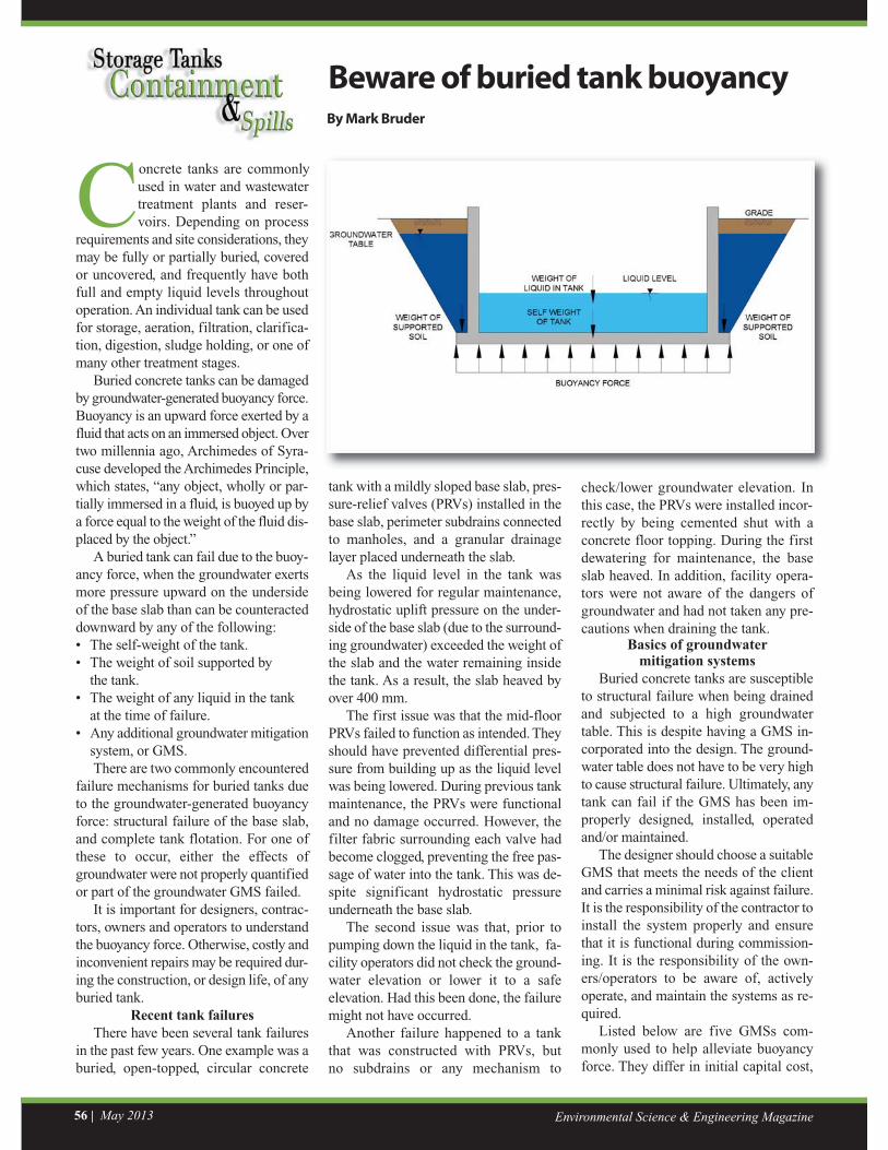
Buried concrete tanks can be damagedby groundwater-generated buoyancy force.Buoyancy is an upward force exerted by afluid that acts on an immersed object. Overtwo millennia ago, Archimedes of Syra-cuse developed the Archimedes Principle,which states, “any object, wholly or par-tially immersed in a fluid, is buoyed up bya force equal to the weight of the fluid dis-placed by the object.”
A buried tank can fail due to the buoy-ancy force, when the groundwater exertsmore pressure upward on the undersideof the base slab than can be counteracteddownward by any of the following: • The self-weight of the tank.• The weight of soil supported by the tank. • The weight of any liquid in the tank at the time of failure.• Any additional groundwater mitigation system, or GMS.
There are two commonly encounteredfailure mechanisms for buried tanks dueto the groundwater-generated buoyancyforce: structural failure of the base slab,and complete tank flotation. For one ofthese to occur, either the effects ofgroundwater were not properly quantifiedor part of the groundwater GMS failed.
It is important for designers, contrac-tors, owners and operators to understandthe buoyancy force. Otherwise, costly andinconvenient repairs may be required dur-ing the construction, or design life, of anyburied tank.
Recent tank failuresThere have been several tank failures
in the past few years. One example was aburied, open-topped, circular concrete
check/lower groundwater elevation. Inthis case, the PRVs were installed incor-rectly by being cemented shut with aconcrete floor topping. During the firstdewatering for maintenance, the baseslab heaved. In addition, facility opera-tors were not aware of the dangers ofgroundwater and had not taken any pre-cautions when draining the tank.
Basics of groundwater mitigation systems
Buried concrete tanks are susceptibleto structural failure when being drainedand subjected to a high groundwatertable. This is despite having a GMS in-corporated into the design. The ground-water table does not have to be very highto cause structural failure. Ultimately, anytank can fail if the GMS has been im-properly designed, installed, operatedand/or maintained.
The designer should choose a suitableGMS that meets the needs of the clientand carries a minimal risk against failure.It is the responsibility of the contractor toinstall the system properly and ensurethat it is functional during commission-ing. It is the responsibility of the own-ers/operators to be aware of, activelyoperate, and maintain the systems as re-quired.
Listed below are five GMSs com-monly used to help alleviate buoyancyforce. They differ in initial capital cost,
Environmental Science & Engineering Magazine56 | May 2013
Beware of buried tank buoyancyBy Mark Bruder
May 2013 | 57www.esemag.com
simplicity of installation, lifecycle func-tionality and risk of failure.
Tank dead weightThe tank dead weight can be increased
by thickening the base slab and/or walls.This downward permanent dead weightdirectly counteracts the upward buoyancyforce.
Pros: Full restraint against flotationcan be achieved. No maintenance or ac-tive operation by plant staff is required.The system is simple to design and con-struct.
Con: This approach can be uneco-nomical if the slab/wall thicknesses be-come excessive.
Soil on the toes Additional dead weight can be found
within the wedge of soil that is supportedon the toes of the base slab. The wider thetoe, the larger the soil wedge that be-comes activated when subjected to uplift.
Pros: Full restraint against flotationcan be achieved. No maintenance or ac-tive operation by plant staff is required.The system is simple to design and con-struct.
Cons: This can be uneconomical if the
toe width becomes excessive due to in-creased excavation volume. The excava-tion method, type of backfill, andproximity to existing structure must beconsidered prior to construction. The baseslab must be capable of spanning the tank.
SubdrainsSubdrains can be installed around the
perimeter of the tank walls, or underneaththe base slab. Typically, the walls arebackfilled with free-draining granularmaterial. Subdrains are wrapped with fil-ter fabric (to prevent fine soil particlesfrom clogging the perforated pipe), and adrainage layer may be installed under-neath the base slab. The subdrains are tiedinto a manhole, so the groundwater tablecan be monitored and lowered to any el-evation by pumping.
Pros: This is effective at lowering thegroundwater table. Installation is straight-forward and not overly expensive.
Cons: The system requires activemonitoring, operation and cleaning. Fa-cility operators may rely too heavily onthe continued performance of the system.Settlement of nearby structure may occur
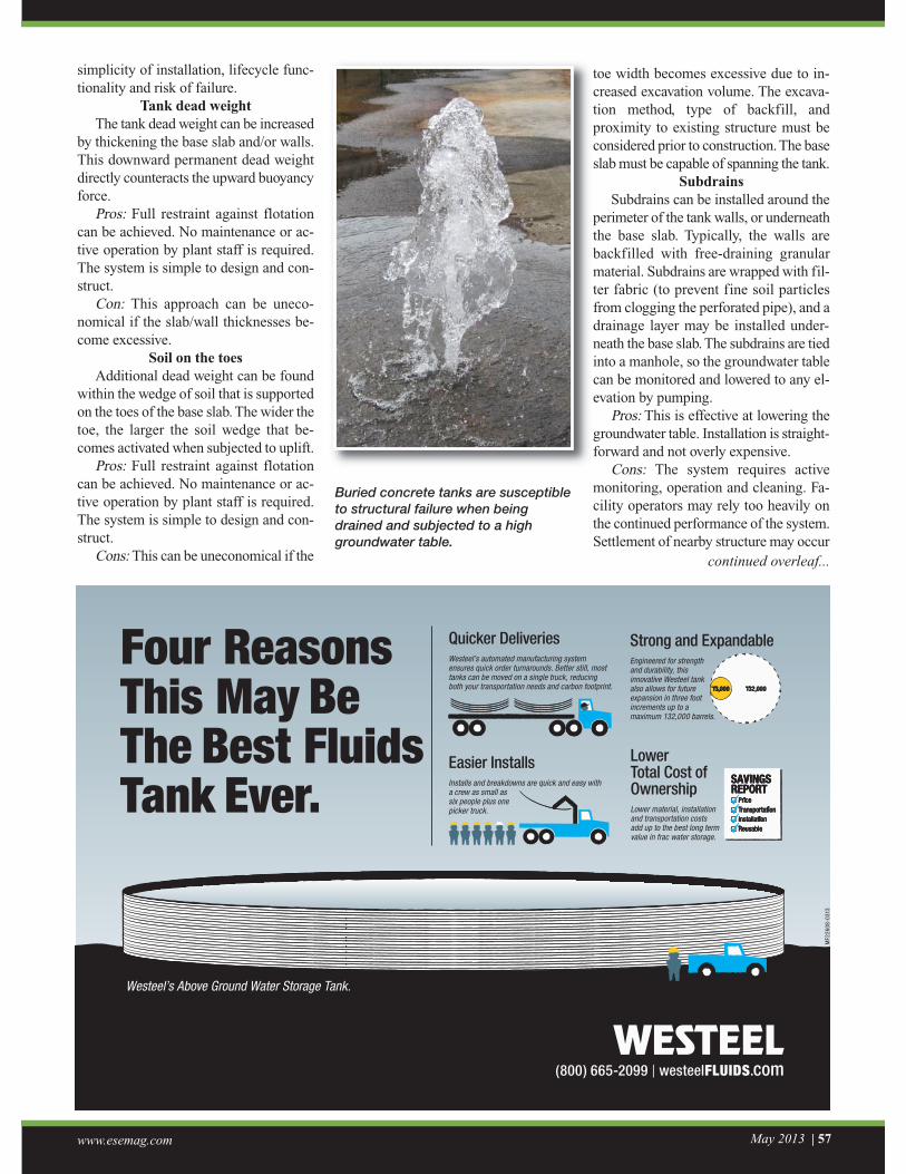
Buried concrete tanks are susceptibleto structural failure when beingdrained and subjected to a highgroundwater table.
continued overleaf...
(800) 665-2099 | westeelFLUIDS.com
Four Reasons This May Be The Best Fluids Tank Ever.
Easier InstallsInstalls and breakdowns are quick and easy with a crew as small as six people plus one picker truck.
Quicker DeliveriesWesteel’s automated manufacturing system ensures quick order turnarounds. Better still, most tanks can be moved on a single truck, reducing both your transportation needs and carbon footprint.
Lower Total Cost of OwnershipLower material, installation and transportation costs add up to the best long term value in frac water storage.
SAVINGSREPORT Price Transportation Installation Reusable
SAVINGSREPORT Price Transportation Installation Reusable
Strong and ExpandableEngineered for strength and durability, this innovative Westeel tank also allows for future expansion in three foot increments up to a maximum 132,000 barrels.
13,000 132,000
Westeel’s Above Ground Water Storage Tank.
MF2
2608
-031
3
Environmental Science & Engineering Magazine58 | May 2013
when the groundwater table is lowered.This approach may not be practical forsites with a very high groundwater table.
Pressure-relief valvesPRVs can be installed in the base slab
or walls depending on the process re-quirements and structural design. Thevalves open one-way into the tank whenthe pressure outside is greater than thepressure inside. As water slowly seepsinto the tank, groundwater pressure is al-leviated.
Pros: This system is effective at alle-viating groundwater pressure, and ishighly economical.
Cons: It requires occasional cleaningto prevent blockage. If not properly in-stalled, content of the tank may leak out.The PRVs may not be able to fully drainthe tank, when the groundwater elevationbalances inside the tank.
AnchorsAnchors can be installed to fully re-
strain the tank. Options include screwpiles that activate a wedge of soil, rockanchors that mechanically grip a rocklayer below, and caissons that rely ondead weight. A successful design in-cludes economic pile spacing and aproper connection to the base slab.
Pros: Full restraint against flotationcan be achieved. No maintenance or ac-tive operation by plant staff is required.The anchors are simple to design andconstruct.
Cons: This can be uneconomical with-out an optimized design, or if costly ex-tras arise during construction. It is not anoption for sites with unfavourable soiltypes.
Installation and operationFor a GMS to function, all components
must be properly designed, installed, op-erated and maintained. The system is onlyas strong as its weakest link. Typically, itcosts far more to repair a tank after it hasfailed, than to spend time and money dur-ing the design or construction phases toimplement a suitable GMS.
Components that require active oper-
ation and/or maintenance by plant staffinclude subdrains, manholes, pumps andPRVs. When a tank needs cleaning andmust be emptied, plant staff should firstcheck the groundwater elevation in themanhole. If it is too high, then a pump islowered into the manhole. By means ofthe free-draining granular backfill and/orbase slab drainage layer, water travelsthrough the subdrains into the manholeand is pumped away. Eventually, ground-water elevation is brought down to a safelevel. Occasionally, PRVs require clean-ing to ensure they are not clogged. Anycomponent that requires active operationor maintenance includes a life cycle costand increased risk of failure.
Avoiding structural failures defini-tively and economically has no all-inclu-sive answer. All available mitigationsystems should be considered for each in-dividual tank design and site-specificconditions. This can ensure optimal per-formance, without excessive capital orlife cycle costs.
Mark Bruder, P.Eng., is with R.V. Anderson Associates Ltd.
E-mail: [email protected]
STORMWATERSTORAGE MODULES
"
Phone: 610-236-1100Email: [email protected]: www.brentwoodindustries.com


![[PPT]Grillage Analysis for Slab & Pseudo-Slab Bridge Decksenggprog.com/Downloads/Lectures/BridgeEngg/Lecture No. 3... · Web viewTitle Grillage Analysis for Slab & Pseudo-Slab Bridge](https://static.fdocuments.us/doc/165x107/5adedacf7f8b9afd1a8beaa6/pptgrillage-analysis-for-slab-pseudo-slab-bridge-no-3web-viewtitle-grillage.jpg)