Influence of Slab Length on behavior of Floating Slab …163-166)-12-025.pdfInfluence of Slab Length...
4
IJR International Journal of Railway Vol. 5, No. 4 / December 2012, pp. 163-166 Vol. 5, No. 4 / December 2012 - 163 - The Korean Society for Railway Influence of Slab Length on behavior of Floating Slab Track by Rail-slab-isolator Longitudinal Interaction Huan Ha Nguyen*, Seung Yup Jang** and Wonseok Chung † Abstract Many different types of floating slab track have been developed and installed around the world to reduce vibrations and noise originating in the surrounding environment. The main objective of this study is to examine the influence of slab length on behavior of floating slab track based on rail-slab-isolator interaction. The floating slab track is modeled by the connection between rail, slab, isolator, and slab mat in the transition zone. All elements were assembled in a simplified two-dimensional (2D) finite element model (FEM). The maximum length of FST is then investigated based on the max- imum additional rail stress criterion as described in UIC 774-3R since no fully accepted design criteria for the slab length in FST systems currently exist. Keywords : Floating slab track, Rail stress, Interaction analysis 1. Introduction The passage of railway vehicles generates mechanical vibrations in a wide range of frequencies. Thus, the place- ment of structural vibration isolation systems is required to reduce vibrations and noise in the surrounding environ- ment. It is widely known that floating slab track (FST) systems are the most effective and reliable solution for prevention of mechanical vibrations and ground-borne noise generated by passing trains (Lombaert et al., 2006). Many different types of FST have been developed and installed around the world (Bilow and Randich, 2000). In Korea, FST such as that shown in Fig. 1 has successfully been developed and tested, and one such is currently being constructed in the test-bed of a commercial railway line. FST typically consist of simple masses and springs that can isolate vibrations due to wheel-rail interactions. In an FST system, a continuous welded rail (CWR) is fixed to a massive concrete slab through rail pads with isolators under the concrete track. Although FST is more expensive and require greater section heights because of the isolator, this relatively high cost is more than offset by the reduced noise and vibration. However, the effect of slab length—an important factor in FST (Yuan et al., 2009)—has not yet been fully researched. The main objective of this study is to examine the behavior of FST and to determine the maximum length of an FST based on the maximum additional rail stress cri- terion as described in UIC 774-3R. The criterion for the maximum additional tensile and compressive rail stress limit is 92 MPa, as described in the International Union of Railways (UIC) code (2001). 2. Floating Slab Track The floating slab track considered in this study typically consists of mass and springs that can isolate vibrations due to wheel-rail interactions. In FST system, a continuously welded rail (CWR) is fixed onto a massive concrete track slab through rail fastenings, and isolators are inserted under the slab. Although FST is more expensive and requires greater section heights because of the thicker slab, this relatively high cost can be offset by the reduced noise and vibration. In Korea, this new kind of FST shown in Fig. 1 has been successfully developed and tested, and is currently being constructed in the test-bed of a commer- cial railway line. † * ** Corresponding author: Wonseok Chung, Kyung Hee University E-mail : [email protected] Graduate Student, Kyung Hee University Senior Researcher, Korea Railroad Research Institute
Transcript of Influence of Slab Length on behavior of Floating Slab …163-166)-12-025.pdfInfluence of Slab Length...
IJR International Journal of Railway
Vol. 5, No. 4 / December 2012, pp. 163-166
Vol. 5, No. 4 / December 2012 − 163 −
The Korean Society for Railway
Influence of Slab Length on behavior of Floating Slab Track
by Rail-slab-isolator Longitudinal Interaction
Huan Ha Nguyen*, Seung Yup Jang** and Wonseok Chung†
Abstract
Many different types of floating slab track have been developed and installed around the world to reduce vibrations and
noise originating in the surrounding environment. The main objective of this study is to examine the influence of slab
length on behavior of floating slab track based on rail-slab-isolator interaction. The floating slab track is modeled by the
connection between rail, slab, isolator, and slab mat in the transition zone. All elements were assembled in a simplified
two-dimensional (2D) finite element model (FEM). The maximum length of FST is then investigated based on the max-
imum additional rail stress criterion as described in UIC 774-3R since no fully accepted design criteria for the slab
length in FST systems currently exist.
Keywords : Floating slab track, Rail stress, Interaction analysis
1. Introduction
The passage of railway vehicles generates mechanical
vibrations in a wide range of frequencies. Thus, the place-
ment of structural vibration isolation systems is required to
reduce vibrations and noise in the surrounding environ-
ment. It is widely known that floating slab track (FST)
systems are the most effective and reliable solution for
prevention of mechanical vibrations and ground-borne
noise generated by passing trains (Lombaert et al., 2006).
Many different types of FST have been developed and
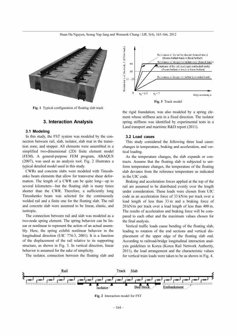
installed around the world (Bilow and Randich, 2000). In
Korea, FST such as that shown in Fig. 1 has successfully
been developed and tested, and one such is currently being
constructed in the test-bed of a commercial railway line.
FST typically consist of simple masses and springs that
can isolate vibrations due to wheel-rail interactions. In an
FST system, a continuous welded rail (CWR) is fixed to a
massive concrete slab through rail pads with isolators
under the concrete track. Although FST is more expensive
and require greater section heights because of the isolator,
this relatively high cost is more than offset by the reduced
noise and vibration.
However, the effect of slab length—an important factor
in FST (Yuan et al., 2009)—has not yet been fully
researched. The main objective of this study is to examine
the behavior of FST and to determine the maximum length
of an FST based on the maximum additional rail stress cri-
terion as described in UIC 774-3R. The criterion for the
maximum additional tensile and compressive rail stress
limit is 92 MPa, as described in the International Union of
Railways (UIC) code (2001).
2. Floating Slab Track
The floating slab track considered in this study typically
consists of mass and springs that can isolate vibrations due
to wheel-rail interactions. In FST system, a continuously
welded rail (CWR) is fixed onto a massive concrete track
slab through rail fastenings, and isolators are inserted
under the slab. Although FST is more expensive and
requires greater section heights because of the thicker slab,
this relatively high cost can be offset by the reduced noise
and vibration. In Korea, this new kind of FST shown in
Fig. 1 has been successfully developed and tested, and is
currently being constructed in the test-bed of a commer-
cial railway line.
†
*
**
Corresponding author: Wonseok Chung, Kyung Hee University
E-mail : [email protected]
Graduate Student, Kyung Hee UniversitySenior Researcher, Korea Railroad Research Institute
− 164 −
Huan Ha Nguyen, Seung Yup Jang and Wonseok Chung / IJR, 5(4), 163-166, 2012
3. Interaction Analysis
3.1 Modeling
In this study, the FST system was modeled by the con-
nection between rail, slab, isolator, slab mat in the transi-
tion zone, and stopper. All elements were assembled in a
simplified two-dimensional (2D) finite element model
(FEM). A general-purpose FEM program, ABAQUS
(2007), was used as an analysis tool. Fig. 2 illustrates a
typical detailed model used in this study.
CWRs and concrete slabs were modeled with Timosh-
enko beam elements that allow for transverse shear defor-
mation. The length of a CWR can be quite long—up to
several kilometers—but the floating slab is many times
shorter than the CWR. Therefore, a sufficiently long
Timoshenko beam was selected for the continuously
welded rail and a finite one for the floating slab. The rail
and concrete slab were assumed to be linear, elastic, and
isotropic.
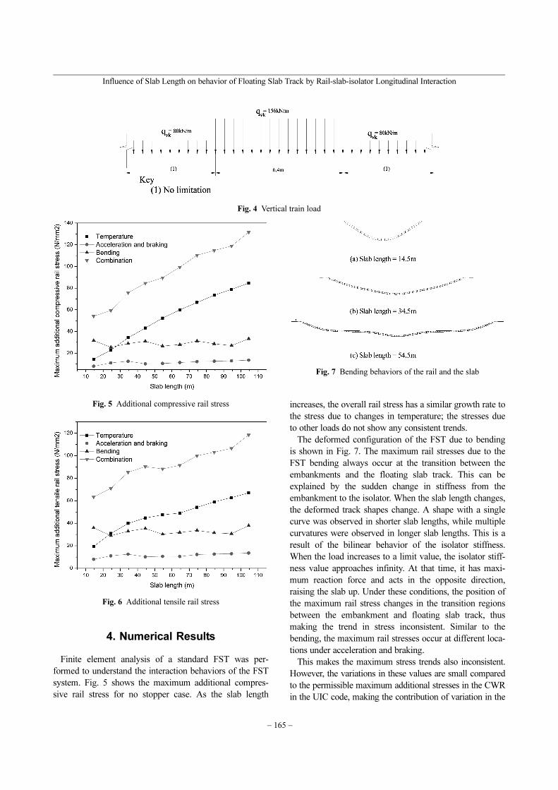
The connection between rail and slab was modeled as a
two-node spring element. The spring behavior can be lin-
ear or nonlinear to represent the action of an actual assem-
bly. Here, the spring exhibit nonlinear behavior in the
longitudinal direction (UIC 774-3, 2001). It is a function
of the displacement of the rail relative to its supporting
structure, as shown in Fig. 3. In vertical direction, linear
behavior is assumed for the sake of simplicity.
The isolator, connection between the floating slab and
the rigid foundation, was also modeled by a spring ele-
ment whose stiffness acts in a fixed direction. The isolator
spring stiffness was identified by experimental tests in a
Land transport and maritime R&D report (2011).
3.2 Load cases
This study considered the following three load cases:
changes in temperature, braking and acceleration, and ver-
tical loading.
As the temperature changes, the slab expands or con-
tracts. Assume that the floating slab is subjected to uni-
form temperature changes, the temperature of the floating
slab deviates from the reference temperature as indicated
in the UIC code.
Braking and acceleration forces applied at the top of the
rail are assumed to be distributed evenly over the length
under consideration. These loads were chosen from UIC
code as an acceleration force of 33 kN/m per track over a
load length of less than 33 m and a braking force of
20 kN/m per track over a load length of less than 400 m.
The results of acceleration and braking force will be com-
pared to each other and the maximum values chosen for
the final analysis.
Vertical traffic loads cause bending of the floating slab,
leading to rotation of the end sections and vertical dis-
placement of the upper edge of the floating slab end.
According to railroad-bridge longitudinal interaction anal-
ysis guidelines in Korea (Korea Rail Network Authority,
2011), the load arrangement and the characteristic values
for vertical train loads were taken to be as shown in Fig. 4.
Fig. 1 Typical configuration of floating slab track
Fig. 2 Interaction model for FST
Fig. 3 Track model
Influence of Slab Length on behavior of Floating Slab Track by Rail-slab-isolator Longitudinal Interaction
− 165 −
4. Numerical Results
Finite element analysis of a standard FST was per-
formed to understand the interaction behaviors of the FST
system. Fig. 5 shows the maximum additional compres-
sive rail stress for no stopper case. As the slab length
increases, the overall rail stress has a similar growth rate to
the stress due to changes in temperature; the stresses due
to other loads do not show any consistent trends.
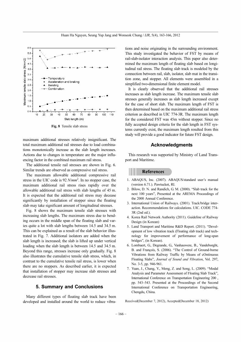
The deformed configuration of the FST due to bending
is shown in Fig. 7. The maximum rail stresses due to the
FST bending always occur at the transition between the
embankments and the floating slab track. This can be
explained by the sudden change in stiffness from the
embankment to the isolator. When the slab length changes,
the deformed track shapes change. A shape with a single
curve was observed in shorter slab lengths, while multiple
curvatures were observed in longer slab lengths. This is a
result of the bilinear behavior of the isolator stiffness.
When the load increases to a limit value, the isolator stiff-
ness value approaches infinity. At that time, it has maxi-
mum reaction force and acts in the opposite direction,
raising the slab up. Under these conditions, the position of
the maximum rail stress changes in the transition regions
between the embankment and floating slab track, thus
making the trend in stress inconsistent. Similar to the
bending, the maximum rail stresses occur at different loca-
tions under acceleration and braking.
This makes the maximum stress trends also inconsistent.
However, the variations in these values are small compared
to the permissible maximum additional stresses in the CWR
in the UIC code, making the contribution of variation in the
Fig. 4 Vertical train load
Fig. 5 Additional compressive rail stress
Fig. 6 Additional tensile rail stress
Fig. 7 Bending behaviors of the rail and the slab
− 166 −
Huan Ha Nguyen, Seung Yup Jang and Wonseok Chung / IJR, 5(4), 163-166, 2012
maximum additional stresses relatively insignificant. The
total maximum additional rail stresses due to load combina-
tions monotonically increase as the slab length increases.
Actions due to changes in temperature are the major influ-
encing factor in the combined maximum rail stress.
The additional tensile rail stresses are shown in Fig. 6.
Similar trends are observed as compressive rail stress.
The maximum allowable additional compressive rail
stress in the UIC code is 92 N/mm2. In no stopper case, the
maximum additional rail stress rises rapidly over the
allowable additional rail stress with slab lengths of 45 m.
It is expected that the additional rail stress may decease
significantly by installation of stopper since the floating
slab may take significant amount of longitudinal stresses.
Fig. 8 shows the maximum tensile slab stresses with
increasing slab lengths. The maximum stress due to bend-
ing occurs in the middle span of the floating slab and var-
ies quite a lot with slab lengths between 14.5 and 34.5 m.
This can be explained as a result of the slab behavior illus-
trated in Fig. 7. Additional isolators are added when the
slab length is increased; the slab is lifted up under vertical
loading when the slab length is between 14.5 and 34.5 m.
Beyond this range, stresses increase only gradually. Fig. 8
also illustrates the cumulative tensile slab stress, which, in
contrast to the cumulative tensile rail stress, is lower when
there are no stoppers. As described earlier, it is expected
that installation of stopper may increase slab stresses and
decrease rail stresses.
5. Summary and Conclusions
Many different types of floating slab track have been
developed and installed around the world to reduce vibra-
tions and noise originating in the surrounding environment.
This study investigated the behavior of FST by means of
rail-slab-isolator interaction analysis. This paper also deter-
mined the maximum length of floating slab based on longi-
tudinal rail stress. The floating slab track is modeled by the
connection between rail, slab, isolator, slab mat in the transi-
tion zone, and stopper. All elements were assembled in a
simplified two-dimensional finite element model.
It is clearly observed that the additional rail stresses
increases as slab length increase. The maximum tensile slab
stresses generally increases as slab length increased except
for the case of short slab. The maximum length of FST is
then determined based on the maximum additional rail stress
criterion as described in UIC 774-3R. The maximum length
for the considered FST was 45m without stopper. Since no
fully accepted design criteria for the slab length in FST sys-
tems currently exist, the maximum length resulted from this
study will provide a good indicator for future FST design.
Acknowledgments
This research was supported by Ministry of Land Trans-
port and Maritime.
1. ABAQUS, Inc. (2007). ABAQUS/standard user’s manual
(version 6.71.). Pawtucket, RI.
2. Bilow, D. N. and Randich, G. M. (2000). “Slab track for the
next 100 years”, Presented at the AREMA Proceedings of
the 2000 Annual Conference.
3. International Union of Railways. (2001). Track/bridge inter-
action. Recommendations for calculations. UIC. CODE 774-
3R (2nd ed.).
4. Korea Rail Network Authority (2011). Guideline of Railway
Design (in Korean)
5. Land Transport and Maritime R&D Report. (2011). “Devel-
opment of low vibration track (Floating slab track) and tech-
nology for improvement of performance of long-span
bridges”, (in Korean).
6. Lombaert, G., Degrande, G., Vanhauwere, B., Vandeborght,
B. and François, S. (2006). “The Control of Ground-borne
Vibrations from Railway Traffic by Means of cOntinuous
Floating Slabs”, Journal of Sound and Vibration, Vol. 297,
No. 3-5, pp. 946-961.
7. Yuan, J., Chang, Y., Meng, Z. and Song, L. (2009). “Modal
Analysis and Parameter Assessment of Floating Slab Track”,
International Conference on Transportation Engineering 200 ,
pp. 543–543. Presented at the Proceedings of the Second
International Conference on Transportation Engineering,
Chengdu, China.
Received(December 7, 2012), Accepted(December 18, 2012)
Fig. 8 Tensile slab stress