BEST SHEDS PTY LTD Instruction Manual · this prevents the purlins from sliding down the rafters...
25
Best Sheds Pty Ltd – Instruction Manual August 2012 Page 1 BEST SHEDS PTY LTD Instruction Manual
Transcript of BEST SHEDS PTY LTD Instruction Manual · this prevents the purlins from sliding down the rafters...

Best Sheds Pty Ltd – Instruction Manual August 2012 Page 1
BEST SHEDS PTY LTD Instruction
Manual
Best Sheds Pty Ltd – Instruction Manual August 2012 Page 2
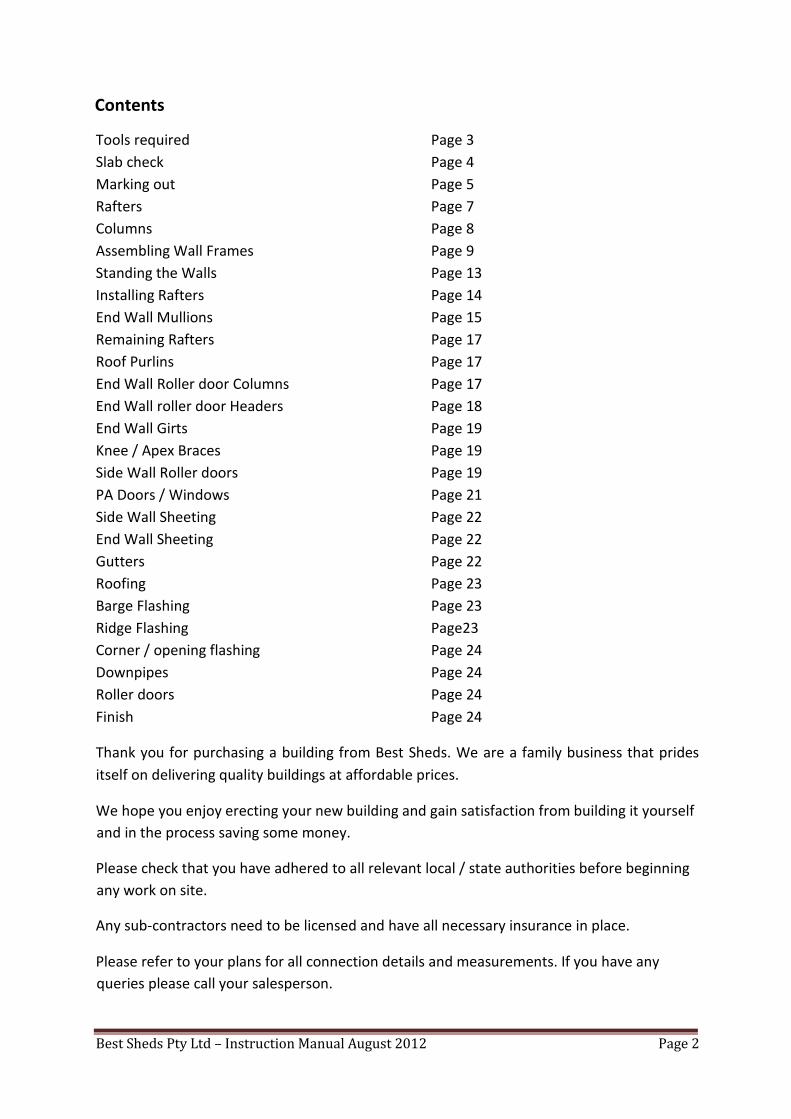
Contents
Tools required Page 3
Slab check Page 4
Marking out Page 5
Rafters Page 7
Columns Page 8
Assembling Wall Frames Page 9
Standing the Walls Page 13
Installing Rafters Page 14
End Wall Mullions Page 15
Remaining Rafters Page 17
Roof Purlins Page 17
End Wall Roller door Columns Page 17
End Wall roller door Headers Page 18
End Wall Girts Page 19
Knee / Apex Braces Page 19
Side Wall Roller doors Page 19
PA Doors / Windows Page 21
Side Wall Sheeting Page 22
End Wall Sheeting Page 22
Gutters Page 22
Roofing Page 23
Barge Flashing Page 23
Ridge Flashing Page23
Corner / opening flashing Page 24
Downpipes Page 24
Roller doors Page 24
Finish Page 24
Thank you for purchasing a building from Best Sheds. We are a family business that prides
itself on delivering quality buildings at affordable prices.
We hope you enjoy erecting your new building and gain satisfaction from building it yourself
and in the process saving some money.
Please check that you have adhered to all relevant local / state authorities before beginning
any work on site.
Any sub-contractors need to be licensed and have all necessary insurance in place.
Please refer to your plans for all connection details and measurements. If you have any
queries please call your salesperson.

Best Sheds Pty Ltd – Instruction Manual August 2012 Page 3
This manual is only a guide to help you build your shed. Please follow all OHS (Occupational
Health & Safety) guidelines. If you are not experienced in building or do not feel confident in
attempting such works, it is recommended you contact a licensed builder to complete the
installation of your shed.
Before lifting walls and inserting hold down bolts, ensure that concrete has been correctly
cured and reached its minimum strength as specified in the engineer’s plans.
What tools will you need?
• Tape measure/s
• Permanent markers
• Electric drill/s
• Hammer drill
• Angle grinder
• Extension leads and power board
• Nibbler (tin snips can be used in place of a nibbler)
• Spirit level
• Ladders
• A range of standard building tools such as Tin Snips, hammer, screw drivers etc.
• Gloves
• Sunscreen / hat
• Roof and gutter silicone, chalking gun
CAUTION
Extreme caution is required when handling and working with steel. Take your time when
moving the steel. Get an assistant to help you to ensure your safety and the safety of others
on site.
Let’s get to work…
Your slab is already poured to the engineer’s specifications provided on your plans.
The first thing that we need to do is check measure that the slabs overall dimensions are
correct and that the slab is square.
The overall dimensions for your slab will be the same as the shed size you ordered
For example if you order a 7.0m x 10.5m building, then your slab will be 7.0m x
10.5m.

Best Sheds Pty Ltd – Instruction Manual August 2012 Page 4
To check the slab is square you need to check that the diagonals of the slab are equal.
If they are equal then the building is square.
For the purpose of the manual we will assume that the slab is square and the overall
measurements are correct.
1. Marking out the building on the slab
Go to sheet 4/5 of your engineering plans and look up what size ‘Column’ and ‘Wall
girt’ your building has from the member schedule.
E.g. Column C15024, this means the column is a ‘C section’, 150mm deep
out of 2.4mm thick steel. So 150mm is the measurement required.
Wall Girt top hat 64 x 1.0, this means a top hat section, 64mm deep
out of 1.0mm thick steel. 64mm is the measurement required.
LENGTH

Best Sheds Pty Ltd – Instruction Manual August 2012 Page 5
MEMBER SCHEDULE
1 RAFTER C15024
2 COLUMN C15024
13 WALL GIRT Top hat 64 x 1.0
Now add the ‘Column’ and ‘Wall girt’ size together to get an overall dimension for
your frame (e.g. 150 + 64 = 214mm). See dwg 1.01.
Now mark the ‘frame overall dimension’ down both side walls of your building (the
gutter walls) and flick a chalk line at this location. This is the inside of the columns.

Best Sheds Pty Ltd – Instruction Manual August 2012 Page 6
The distance between the lines you have now marked is the long point to long point
of the rafters, which you will need in step 2.
2. RAFTERS
Lay 2 rafters out onto the slab with the bottom of the rafters touching at the apex.
Using the apex bracket as a rough guide to set the pitch of the rafters. (Check
the member schedule to see if your building has single or back to back
rafters).
Put the apex bracket in place, check that all of the punching are in line and that the
rafters are still touching. Put in 2 ‘tek’ screws through the apex bracket in to the
rafters (1 screw per rafter) as shown in drawing 2.01 (‘teks’ screw first location). Now
measure long point to long point of the rafters and adjust until the measurement is
the same as in the previous step.
Put 2 more ‘tek’ screws through the apex bracket into the rafter (‘tek’ screw second
location) to lock the rafters at the correct overall width and therefore correct pitch.
Now put all bolts in as per engineering details.
If apex brace is required in your building, bolt these to the rafters now to the
engineering details.
Drawing 2.01
Tip:
Now is a good time to mark your roof purlins onto the rafters (to save doing it from a ladder
later on in the build).
It’s also a good idea to put a temporary screw in the rafter at the base of all purlins. Doing
this prevents the purlins from sliding down the rafters while screwing them off.
Roof purlin spacing can be found in the member schedule on your engineering plans.
Rafter long point to long point

Best Sheds Pty Ltd – Instruction Manual August 2012 Page 7
3. COLUMNS, HAUNCH BRACKETS, BASE BRACKETS
Place the columns out on the slab, at approximate bay spacing’s. Bolt the haunch
bracket and base bracket onto the column to engineer’s details.
(Check the member schedule to see if your building has single or back to back
columns)
Haunch bracket
Base bracket
The end portal frames (front and back) need to have the webs of the c section facing
into the building. This is in case a roller door is to be attached to the column, and
also for aesthetics.
Intermediate portals can face either way, however for aesthetics the webs are
generally faced towards the prominent opening, i.e. roller doors.
LENGTH
WALL GIRT LOCATION

Best Sheds Pty Ltd – Instruction Manual August 2012 Page 8
NOTE: COLUMNS DRAWN OVERSIZE FOR CLARITY
4. ASSEMBLING WALL FRAMES
Assembling the wall frames varies slightly depending on the wall girt size of your
building.
If your girts are TH64075 or TH64100 then continue reading step 4.1
If your wall girts are TH120100 or TH120120 then skip to step 4.2
4.1 Top hat 64mm Option
You need to attach the C80 eave purlin to the top of the columns. The
C80 eave purlin will be flush to the top of the column. The C80 eave
purlin is 64mm deep, making it the same dimension as the TH64 wall
girts.
Drawing 4.1
Your columns are already laid out on the slab, with the haunch and base
brackets bolted on. Now lay out the C80 eave beams down the centre of
the slab (as per drawing 4.2).

Best Sheds Pty Ltd – Instruction Manual August 2012 Page 9
Drawing 4.2
Bay spacing needs to be determined to know the exact location of your
columns. The C80 eave purlin will be the same length as your bay spacing.
Bay spacing on the front and back columns will run to the outside edge of
the column.
On intermediate columns the bay spacing will be in the centre of the
column. As per drawing 4.3
Drawing 4.3
Screw the C80 eave purlin flush to the top of the columns. The number of
screws as per engineer’s details.
Mark the wall girt spacing onto the columns. The lowest girt is located
200mm from the bottom of the column to the top side of the wall girt.
LENGTH
NOTE: COLUMNS DRAWN OVERSIZE FOR CLARITY
WALL GIRT LOCATION
BAY SPACING BAY SPACING BAY SPACING C/C C/C EDGE EDGE

Best Sheds Pty Ltd – Instruction Manual August 2012 Page 10
The remaining girts are spaced evenly. Maximum wall girt spacing
according to engineer’s details (member schedule)
Now lay out the wall girts and screw them into place. Ensure that the
columns are all parallel, and bay spacing measurements are as per
drawing 4.3.
Run a string line at the base of all columns, and check the frame is
square (check diagonals)
4.2 Top hat 120mm Option
Now attach the TH120 eave purlin to the top of the columns. The TH120
eave purlin will be flush to the top of the column. A TH64075 is attached
on top of the TH120 eave purlin to fix the end of the roof sheet off. See
drawing 4.4
Drawing 4.4
Your columns are already laid out on the slab with the haunch and base
brackets bolted on. Now lay out the TH120 eave beams down the centre
of the slab (as drawing 4.5).
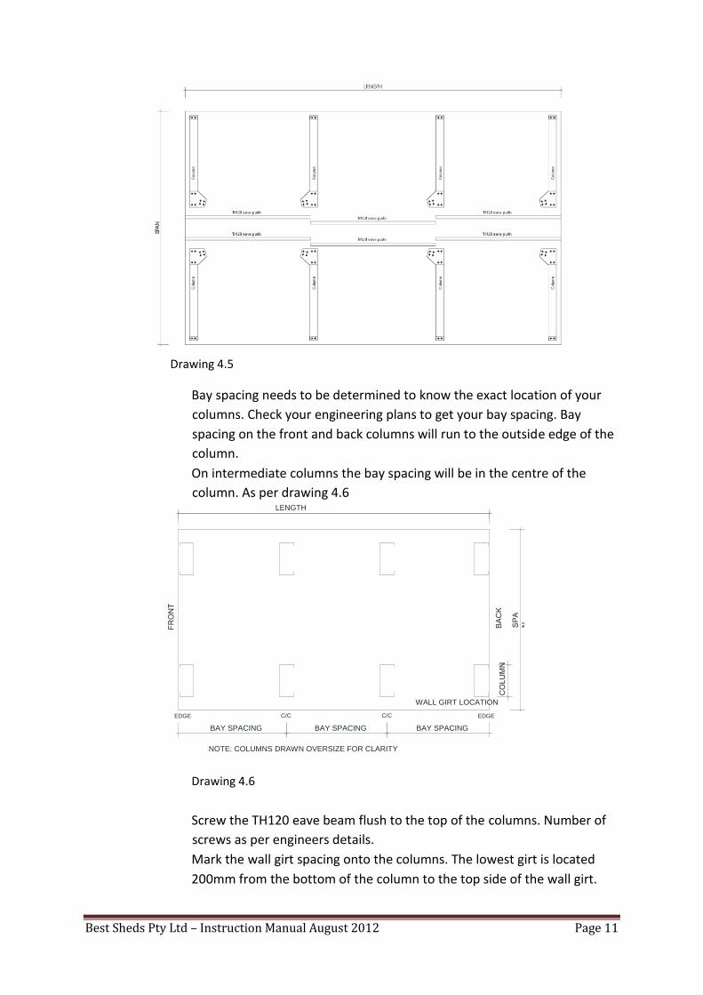
Best Sheds Pty Ltd – Instruction Manual August 2012 Page 11
Drawing 4.5
Bay spacing needs to be determined to know the exact location of your
columns. Check your engineering plans to get your bay spacing. Bay
spacing on the front and back columns will run to the outside edge of the
column.
On intermediate columns the bay spacing will be in the centre of the
column. As per drawing 4.6
Drawing 4.6
Screw the TH120 eave beam flush to the top of the columns. Number of
screws as per engineers details.
Mark the wall girt spacing onto the columns. The lowest girt is located
200mm from the bottom of the column to the top side of the wall girt.
LENGTH
NOTE: COLUMNS DRAWN OVERSIZE FOR CLARITY
WALL GIRT LOCATION
BAY SPACING BAY SPACING BAY SPACING C/C C/C EDGE EDGE

Best Sheds Pty Ltd – Instruction Manual August 2012 Page 12
The remaining girts are spaced evenly. Maximum wall girt spacing
according to engineer’s details (member schedule)
Now lay out the wall girts and screw them into place. Ensure that the
columns are all parallel, and bay spacing measurements are as per
drawing 4.3.
Run a string line at the base of all columns, and check the frame is
square (check diagonals).
Now screw the th64075 into position on top of the Th120 eave purlin, as
per drawing 4.4
Check your engineering plans to see if any side wall strap bracing is
required. If so install strap bracing onto the wall frame.
5. STANDING THE WALLS
Appropriate tie down points, ropes and props are required to assist holding the wall
vertical until you have all hold down bolts in and rafters secured in place.
The larger the shed the more ropes and props you will need.
Ensure you have enough ropes and props to comfortably hold the wall in case a
strong gust of wind comes through.
Do not attempt to lift walls on a windy day.
Once you have all of your ropes and props in position you can stand the wall. The
size of the building will determine how many assistants or the size of crane required
to lift the wall. If using a crane, a spreader bar is required along with long chains so
as to not damage any part of the wall when lifting.
Once the wall is vertical and temporary ropes and props are secured, adjust the wall
so that the first and last columns are flush to the concrete edge, and move inside of
the columns to the line marked on the concrete back in step 1. Ensure the columns
are square off the chalk line, (not twisted) and are plumb (adjust props if necessary).
Drill appropriate size hole with a masonry bit (not included in kit) through the base
bracket into the concrete (hold down bolt size from engineers plan). Hammer in hold
down bolts and tighten.
Repeat step 5 for other side wall.

Best Sheds Pty Ltd – Instruction Manual August 2012 Page 13
Tip
To select appropriate masonry drill bit, find your masonry anchor size (hold down
bolt). The diameter bolt specified is the masonry drill bit size required.
E.g. A sleeve anchor M12 x 75mm, will require a 12mm Masonry drill bit.
6. INSTALLING RAFTERS
The size of your building will determine whether you need a crane to lift rafters into
place, and also whether you need scissor lift/s, mobile scaffolding, ladders to install
rafters, roof battens, roof sheeting etc.
Follow OHS (Occupational Health & Safety) guidelines for working safely on site, in
particular working at heights.
Generally starting at the rear of the building, lift the previously assembled rafters
(step 2) up onto haunch brackets that are already bolted onto columns (step 3). Use
a clamp to help hold the rafter in position.
Align bolt holes and put 1 x temporary ‘tek’ screw through the haunch bracket into
the rafter on each side of the building.
Now install all frame bolts to engineer’s details. Only do them up finger tight for the
moment.
Note: Ensure that the lifting device used to install the rafter is still in place to prevent
the rafter from rolling and possibly tearing the brackets. It is also important to
ensure that the weight of the rafters is on the haunch brackets and the lifting device
in only balancing the rafters.
Using a spirit level, plumb the 2 columns. Adjust props / ropes as necessary.
Now tighten the frame bolts.

Best Sheds Pty Ltd – Instruction Manual August 2012 Page 14
7. END WALL MULLIONS
Check your engineering plans for spacing and number of end wall mullions.
Mark out end wall mullion positions onto the slab.
End wall Mullions will be perpendicular to the rafters.
End wall mullions can face either way, for aesthetics face the flat face (web) of the C
section towards any side wall openings.
Depending on your building span you might have,
1. no end wall mullions
2. One end wall mullion in each end wall, this will be right in the centre on the
apex bracket. This option may require apex bracket bolts being removed and
drilled through the mullion (on Top hat 120 option)
3. two end wall mullions in each end wall, in this case mullions will be located
along each rafter
CHECK FIXINGS WITH ENGINEERS PLANS
End wall
End
wall
mullion
mullion
Rafter
Drawing7.1
End wall mullions are offset end wall girt thickness from the slab edge (end wall girt
size from engineer’s plans).

Best Sheds Pty Ltd – Instruction Manual August 2012 Page 15
Locate your end wall mullions and bolt the base brackets on to pre-punched holes
(to engineer’s drawings).
Mullion
Base bracket
Stand end wall mullion in position and roughly plumb. Check height of mullion to the
top of the rafters and if necessary mark and cut the mullion to ensure it will not
interfere with roof sheeting.
Check your end wall girt size (same as start of step 4) and determine whether you
have 64mm or 120mm end wall girts.
For 64mm end wall girts follow next step (Step 7.1) for
120mm end wall girts go to Step 7.2
7.1 Top hat 64mm end wall girt option
If you have 64mm end wall girts, there is no end wall mullion bracket supplied to
attach the mullion to the rafter. Instead you just screw through the rafter into
the mullion, or alternatively screw through the apex bracket into the mullion (as
per drawing 7.1). No bracket is needed as the rafter and column flange thickness
is the same thickness as end wall girts (64mm).
7.2 Top hat 120mm end wall girt option
If you have 120mm end wall girts, there is an angle bracket which is called an end
wall mullion bracket which will attach the end wall mullion to the rafters. The
bracket is needed as the 120mm top hat is larger than the flange size of the
columns and rafters.
WALL GIRT LOCATION
BAY SPACING C/C EDGE
END WALL GIRT HEIGHT
END WALL MULLION

Best Sheds Pty Ltd – Instruction Manual August 2012 Page 16
Note: It may be necessary to prop and rope the mullion to hold it plumb, and to
ensure it has enough strength to brace all the rafters when in place.
8. REMAINING RAFTERS
Install all remaining rafters as in Step 6.
Be sure to brace all rafters before removing any lifting devices. A good way to do this
is to run 2 rows of roof purlins (one each side of the roof up near the apex) back to
the first rafter you installed that has mullions in place, and use ropes and props to
hold everything steady.
Ensure all rafters are parallel and plumb.
On large buildings it may be necessary to install all the purlins in the first bay and
install the roof bracing to hold the heavier rafters in place.
9. ROOF PURLINS
Install all roof purlins as per engineering plans.
Ensure you put the correct number of screws per connection.
Install any roof bracing as per engineering plans
10. END WALL ROLLER DOOR/S COLUMNS
Refer to your engineering plans for end wall roller door locations. If there are no end
wall roller doors in your building then continue to step 12.
End roller doors are supplied with ‘C Section’ roller door columns to frame the
opening.
Roller doors may be located on one end or both of the end wall columns.
Detailed instructions for installing your roller door are supplied in the roller door
bracket box.

Best Sheds Pty Ltd – Instruction Manual August 2012 Page 17
The width of roller door frame openings will be narrower than the actual door
(curtain) width by either 50mm or 100mm depending on door track size. Check your
roller door instructions for correct opening size.
Mark out the position of roller door columns on to the concrete slab.
Locate your roller door columns and bolt the base brackets as per
engineer’s drawings.
Roller door
Column
Base bracket
Stand roller door column/s in position and plumb column. Mark the top and bottom
of the rafter onto the roller door column and notch the column as in drawing 10.1.
Stand the roller door column back up in position, fix it to the concrete with masonry
anchors. Now plumb the column and screw/bolt to rafter as per engineer’s plans.
Tip: spray all cuts with Cold Gal, to prevent any corrosion.
Drawing 10.1
11. END WALL ROLLER DOOR/S HEADER
The opening height of the roller door is the same as the height of the roller door
(e.g. 2.5m high door will have a 2.5m clearance under the header beam).
Mark the opening height up both columns and attach end wall girt bracket (which
you will attach the roller door header to).

Best Sheds Pty Ltd – Instruction Manual August 2012 Page 18
Screw header beam into place, ensuring the beam is level across the opening Check
the overall height of your roller door rolled up (usually 350mm – 600mm) and
ensure that the door will fit in space allowed above the header. If not the header
height will need to be lowered.
12. END WALL GIRTS
Install End Wall Girt brackets on the inside of end wall columns and Gable End Roller
door Posts (only if you have end wall roller doors). End Wall Girts spacing as per
engineer’s plans.
End wall
end wallgirtend
wall
End wall girt bracket Girt
bracket
End walled wall column column
Girt
View from inside building TH64 OPTION View from inside building end wall
Girt end
wall girt
bracket
End wall
column
End wall Girt bracket
End wall Column
Roller door Header
End wall Column
End wall Girt bracket
End wall
Girt

Best Sheds Pty Ltd – Instruction Manual August 2012 Page 19
TH120 OPTION
13. KNEE BRACES
Install knee braces (if required) as per engineer’s plans
14. FLY BRACING
Install fly Bracing (if required) as per engineer’s plans
15. SIDE WALL ROLLER DOORS (if included)
Refer to your engineering plans for side wall roller door locations. If there are no side
wall roller doors in your building then continue to step 16.
Side roller doors are supplied with ‘Z Section’ roller door columns too frame the
opening.
Detailed instructions for installing your roller door are supplied in the roller door
bracket box.
The width of roller door frame openings will be narrower than the actual door
(curtain) width by either 50mm or 100mm depending on door track size. Check your
roller door instructions for correct Opening size.
Mark out the position of roller door columns onto the concrete slab.
Plumb these lines up onto the wall girts and cut the wall girts at this location.
Locate your roller door columns and bolt the base brackets (to engineer’s drawings).
Stand roller door column/s in position and plumb column. Mark the top and bottom
of the eave purlin onto the roller door column and notch the ‘Z section’ column
around the eave purlin.
Stand the roller door column back up in position, fix it to the concrete with masonry
anchors. Now plumb the column and screw/bolt to rafter as per engineer’s plans.
Tip: spray all cuts with Cold Gal, to prevent any corrosion

Best Sheds Pty Ltd – Instruction Manual August 2012 Page 20
16. PA (PERSONAL ACCESS) DOORS, GLASS SLIDING DOORS (if included) See Images at
End of Manual
All door jambs (to suit 64mm or 120mm wall girt) are supplied 2.7m long. On all
buildings with an eave height 2.7m or less, the jamb will attach to the eave
purlin. In all other cases it will attach to the next wall girt above the door head.
Check plans for door location.
Measure the opening required for your door, and mark this onto the concrete slab.
Plumb these marks up onto the wall girts, and cut the wall girts.
Locate your PA door jambs and screw on the base brackets (to engineer’s drawings).
Stand PA door jambs in position and plumb. Mark the top and bottom of the eave
purlin (or wall girt) onto the PA door jambs and notch the jamb around the eave
purlin (wall girt).
Stand the roller door column back up in position, fix it to the concrete with masonry
anchors. Now plumb the column and screw to eave purlin (wall girt) as per
engineer’s plans.
Screw all wall girts to the jamb. Ensure girts remain level.
Tip: mark the opening 5-10mm larger than required opening to allow for inaccuracy
when cutting wall girts.

Best Sheds Pty Ltd – Instruction Manual August 2012 Page 21
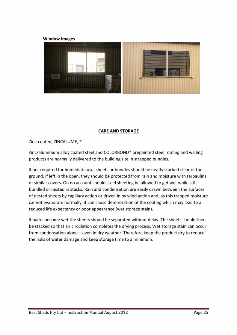
17. WINDOWS (if included) see Images at end of Manual Window
width is 2 corrugated sheets wide.
It’s best to mark the approximate position of the window on the face of the wall
girts. Then start wall sheeting and when you come to your marks, adjust them to suit
the wall sheeting (this saves having to cut the sheeting down the sides of the
windows).
Sit the window on the wall girt, with the bottom fin of the window running down the
face of the wall girt. Now slide the window along so the side fin of the window goes
behind the wall sheet already in place.
Screw the window to the wall girts, and place a screw through the wall sheeting into
the top fin of the window.
Now measure and cut sheets above and below the window and screw them into
place.
Continue wall sheeting.
18. SIDE WALL SHEETING
Locate the side wall sheeting, sheets will be approximately 20mm longer than
column length (this allows the sheets to overlap the concrete slab).
Top of side wall sheets will be flush with top of Eave Purlins.
Sheet laps need to face away from prevailing winds.
Check to see if insulation is supplied for your walls. If so cut insulation to length and
install as you are installing the wall sheets.
If there are any openings in the side walls, cut sheets as required to match frame
opening already installed.
Check each sheet is plumb before screwing off.
19. END WALL SHEETING
Locate the end wall sheeting. End wall sheets are all one length (longest length
required), and will need to be cut to the rake of the roof onsite.
Sheets will overlap slab same length as side wall sheeting Top of
end wall sheets are to be cut to underside of roof sheeting.
Sheet laps need to face away from prevailing winds.
If there are any openings in the end walls, cut sheets as required to match frame
opening already installed.
Check each sheet is plumb before screwing off.

Best Sheds Pty Ltd – Instruction Manual August 2012 Page 22
20. GUTTERS
Work out how many and the location of your downpipes. Downpipes should be at
maximum 12.0m spacing’s down the side walls of the building.
Cut the downpipe nozzles out of the gutters (to suit above) and install nozzle. Ensure
you place silicone on all rivets, and where the nozzle meets the gutter.
Install stop ends on the appropriate gutters. Again ensure you use plenty of silicone,
and make sure you strip the protective plastic back off the guttering and stop ends.
Gutter brackets are now to be installed to the wall sheeting at maximum 1.2m
spacing’s.
Mark a chalk line onto the wall sheeting, one end (high end) starting at the top of
wall sheeting, and the other end where the downpipe is (low end) having a minimum
fall of 1:500.
E.g. A 7.0m long gutter must drop 1mm every 500mm, 7000mm / 500 = 14
Building minimum fall = 14mm
Rivet gutter brackets the ridge of the wall sheeting.
Hook the gutter onto the end of the gutter bracket and rotate into place. Ensure you
place silicone on all gutter joins, and lap the gutters in the direction of the fall of the
roof.
21. ROOFING
Check engineer’s plans for any strap bracing required in the roof frame and ensure
all bracing is installed as per plans.
Screw all sheeting off to engineer’s plans.
Check to see if insulation is supplied under your roof sheets. If so cut insulation to
length and install as you are laying the roof sheets.
Turn up ends of sheets 60 degrees (each valley of the sheet) at the ridge line.
Ensure you lap the sheeting from prevailing weather.
Roof sheeting will overhang wall sheets approx. 50mm into the gutter.
22. BARGE FLASHINGS
Peel the plastic off one barge, lift up into place (either side) and align top of the
barge with the apex (middle) of the building. Screw through the top leg of the barge
into roof purlins. Ensure the barge flashing is tight into the gable end wall sheeting,
and that the barge face is plumb (i.e. not leaning over at the top).
Peel the plastic off the second barge and cut a ‘plumb cut’ on the apex end (plumb
cut will be roof pitch). Lift the barge up into position, overlap this second barge
510mm over the first barge. Screw barge into place.
Now put either coloured rivets or wall screws (10-16x16) through the vertical leg of
the barge every 4th rib of the wall sheeting.
Plumb cut the ends of the 2 barges flush with the end of the gutters. Now
repeat this step for the other end of the building.

Best Sheds Pty Ltd – Instruction Manual August 2012 Page 23
23. RIDGE FLASHING
Ensure ridge capping is flush with the face of the barges.
A good tip is to trim the ends of the ridge (where they run to the gable ends) to a
tapper for aesthetics when looking up at the ridge from the ground.
24. CORNER FLASHINGS
Locate corner flashings, peel off protective plastic and install them to the corners of
the building using either coloured rivet or walls screw (10-16x16).
Ensure corner flashings are watertight, and will not rattle in the wind. Generally
there should be a maximum of 2 fixings every 1.0m down the length of the flashing
(one fixing each side of the flashing).
25. OPENING FLASHINGS
Opening flashing same as corner flashings. Only difference being you will have to
notch the flashings to step over the slab. And in the case of headers, each end will
need to be notched to suit side opening flashings.
26. DOWNPIPES
Locate downpipes and peel off plastic protective coating. Fix the downpipes to the
nozzles with 4 x rivets or wall screws (10-16x16) per downpipe. Fix the bottom of the
downpipe with a roof screw from inside the building, through the bottom wall girt
into the downpipe.
BARGE FLASHING RIDGE
TRIM RIDGE FLASHING TO BARGE DEPTH.
LEAVE A 10mm COVER MIN WHERE THE BARGES OVERLAP EACH OTHER.
ENSURE YOU PLACE PLENTY OF SILICON AT THIS LOCATION.

Best Sheds Pty Ltd – Instruction Manual August 2012 Page 24
27. ROLLER DOORS
Install roller door/s to manufacturers specifications (supplied in roller door box). All
roller door tracks must be fasten down with 2 screws per lug.
28. FINISH
Time to do a once over of the building, check that all bolts have been tightened and
bracing is installed.
Sweep off the roof, and wipe over all walls to remove any swarf from cutting or
drilling during the build process.
Sweep off the slab and remove all rubbish. Make sure you get every last screw off
the slab or driveway before bringing any vehicles into the building.
Congratulations, you are now all done. Time to enjoy your new building.
PA Door Images
Best Sheds Pty Ltd – Instruction Manual August 2012 Page 25
Window Images
CARE AND STORAGE
Zinc-coated, ZINCALUME, ®
Zinc/aluminium alloy coated steel and COLORBOND® prepainted steel roofing and walling
products are normally delivered to the building site in strapped bundles.
If not required for immediate use, sheets or bundles should be neatly stacked clear of the
ground. If left in the open, they should be protected from rain and moisture with tarpaulins
or similar covers. On no account should steel sheeting be allowed to get wet while still
bundled or nested in stacks. Rain and condensation are easily drawn between the surfaces
of nested sheets by capillary action or driven in by wind action and, as this trapped moisture
cannot evaporate normally, it can cause deterioration of the coating which may lead to a
reduced life expectancy or poor appearance (wet storage stain).
If packs become wet the sheets should be separated without delay. The sheets should then
be stacked so that air circulation completes the drying process. Wet storage stain can occur
from condensation alone – even in dry weather. Therefore keep the product dry to reduce
the risks of water damage and keep storage time to a minimum.