
BASIC ELECTRICAL ENGINEERING...LIST OF EXPERIMENTS HARDWARE EXPERIMENTS To verify KCL and KVL To...
57
BASIC ELECTRICAL ENGINEERING LAB MANUAL Prepared By Ms. SHIPRA JAIN ASSISTANT PROFESSOR Department Of Electrical Engg., JCB University of Science and Technology, YMCA Faridabad, Haryana
Transcript of BASIC ELECTRICAL ENGINEERING...LIST OF EXPERIMENTS HARDWARE EXPERIMENTS To verify KCL and KVL To...

BASIC ELECTRICAL ENGINEERING
LAB MANUAL
Prepared By
Ms. SHIPRA JAIN ASSISTANT PROFESSOR
Department Of Electrical Engg.,
JCB University of Science and Technology, YMCA
Faridabad, Haryana

VISION OF THE DEPARTMENT
Electrical Engineering Department congregates the challenges of new technological advancements to provide comprehensively trained, career focussed , morally strong accomplished graduates,cutting edge researchers by experimental learning which contribute to ever changing global society and serve as competent engineers.
MISSION OF THE DEPARTMENT
To commit excellence in imparting knowledge through incubation and execution of high quality innovative educational programs. To develop the Research oriented culture to build national capabilities for excellent power management. To inculcate and harvest the moral values and ethical behaviour in the students through exposure of self -discipline and personal integrity. To develop a Centre of Research and Education generating knowledge and technologies which lay ground work in shaping the future in the field of electrical engineering.

PROGRAM EDUCATIONAL OBJECTIVES (PEOs) To produce competent electrical engineering graduates with a strong foundation
design, analytics and problem solving skills for successful professional careers in industry, research and public service.
To provide a stimulating research environment so as to motivate the students for higher studies and innovation in the specific and allied domains of electrical engineering.
To encourage the graduates to practice the profession following ethical codes, social responsibility and accountability.
To train students to communicate effectively in multidisciplinary environment. To imbibe an attitude in the graduates for life-long learning process.
PROGRAM OUTCOMES (POs)
Engineering Graduates will be able to: 1. Apply the knowledge of mathematics, science, electrical engineering fundamentals,
and an electrical engineering specialization to the solution of complex electrical engineering problems.
2. Identify, formulate, review research literature, and analyze complex electrical engineering problems reaching substantiated conclusions using first principles of mathematics, natural sciences, and engineering sciences.
3. Design solutions for complex electrical engineering problems and design system components or processes that meet the specified needs with appropriate consideration for the public health and safety, and the cultural, societal, and environmental considerations.
4. Use research-based knowledge and research methods including design of experiments, analysis and interpretation of data, and synthesis of the information to provide valid conclusions.
5. Create, select, and apply appropriate techniques, resources, and modern engineering and IT tools including prediction and modelling to complex electrical engineering activities with an understanding of the limitations.
6. Apply reasoning informed by the contextual knowledge to assess societal, health, safety, legal and cultural issues and the consequent responsibilities relevant to the professional engineering practice.
7. Understand the impact of the professional electrical engineering solutions in societal and environmental contexts, and demonstrate the knowledge of, and need for sustainable development.
8. Apply ethical principles and commit to professional ethics and responsibilities and norms of the engineering practice.
9. Function effectively as an individual, and as a member or leader in diverse teams, and in multidisciplinary settings.
10. Communicate effectively on complex engineering activities with the engineering community and with society at large, such as, being able to comprehend and write effective reports and design documentation, make effective presentations, and give and receive clear instructions.
11. Demonstrate knowledge and understanding of the engineering and management principles and apply these to one’s own work, as a member and leader in a team, to manage projects and in multidisciplinary environments.

12. Recognize the need for, and have the preparation and ability to engage in independent and life-long learning in the broadest context of technological change.
PROGRAM SPECIFIC OUTCOMES (PSOs)
1. To impart State-of-Art knowledge in the field of Electrical Engineering and hand on application based practical training with regular Academic and Industry interaction.
2. To incorporate research environment and innovation projects towards assimilation of global technology in order to meet needs of automation and articulate a higher education system of ethics and mind set for a realistic education.

Course Outcomes:
The students are expected to
1. Get an exposure to common electrical components and their ratings and understand
the usage of common electrical measuring instruments.
2. Different Network theorems for dc circuits.
3. Resonance in RLC circuits
4. Transients in RL and RC transients.
5. Understand the basic concept of transformers and electrical machine

LIST OF EXPERIMENTS
HARDWARE EXPERIMENTS
To verify KCL and KVL
To verify Thevenin's theorem.
To verify Norton‟s theorem.
To verify Super position theorem.
To study frequency response of series RLC circuit and determine resonance
frequency.
To study frequency response of parallel RLC circuit and determine resonance
frequency.
To verify the transient response of series R-L circuit.
To verify the transient response of series R-C circuit.
To find the polarity and turns ratio of a single phase Transformer.
To perform speed control of dc motor by armature voltage control.
To perform speed control of dc motor by field current control.
STUDY EXPERIMENTS
Introduction to real-life resistors, capacitors and inductors. Introduction and use of
measuring instruments – voltmeter, ammeter, multi-meter, oscilloscope.
To study the constructional features and working of three phase Induction motor.
To study the constructional features and working of DC motor.
To study the constructional features and working of Synchronous generator.


INDEX
EXPERIMENT S.No. Page No. Signature

PRECAUTIONS
1. There must be at least two (2) people in the laboratory while working online circuits.
2. Shoes must be worn at all times.
3. Remove all loose conductive jewellery and trinkets, including rings, which may come in contact with
exposed circuits. (Do not wear long loose ties, scarves, or other loose clothing around machines.)
4. Consider all circuits to be "hot" unless proven otherwise.
5. When making measurements, form the habit of using only one hand at a time. No part of a live circuit
should be touched by the bare hand.
6. Keep the body, or any part of it, out of the circuit. Where interconnecting wires and cables are
involved, they should be arranged So that anyone can verify them.
7. Be as neat a possible. Keep the work area and workbench clear of items not used in the experiment.
8. Always check to see that the power switch is OFF before plugging into the outlet. Also, turn
instrument or equipment OFF before unplugging from the outlet.
9. When unplugging a power cord, pull on the plug, not on the cable.
10. When disassembling a circuit, first remove the source of power.
11. No ungrounded electrical or electronic apparatus is to be used in the laboratory unless it is double
insulated or battery operated.
12. Report any damages to equipment, hazards, and potential hazards to the laboratory instructor.
13. Regarding specific equipment, student should read the instruction manual provided by the
manufacturer of the equipment and consult with teacher.
14. Information regarding safe use and possible- hazards should be studied carefully.

EXPERIMENT NO. 1
AIM: To study various types of measuring instruments.
Apparatus: A. Ammeter
B .Voltmeter
C .Wattmeter
D. Resistance ohmmeter
E. Capacitor
F. Inductor
G. Function generator
H. Multimeter
I. CRO (Cathode Ray Oscilloscope)
THEORY:
ELECTRICAL INSTRUMENTS-: The instruments which are used to measure electrical quantities are
called electrical instruments. Such as ammeter, voltmeter, wattmeter, energy meter etc.
TYPES OF ELECTRICAL INSTRUMENTS-:
The electrical instruments may be broadly classified as-:
PRIMARY INSTRUMENTS:-The instruments which give the value of the quantity to be
measured in terms of the constants of the instruments are called primary instruments. The
common example is tangent galvanometer.
SECONDARY INSTRUMENTS:- The instruments which determine the electrical quantity to
be measured directly in terms of deflection are called secondary instruments.These instruments
are called secondary instruments. These instruments are generally used in practical.The
secondary instruments are further classified as:-
INDICATING INSTRUMENTS
INTEGRATING INSTRUMENTS
RECORDING INSTRUMENTS
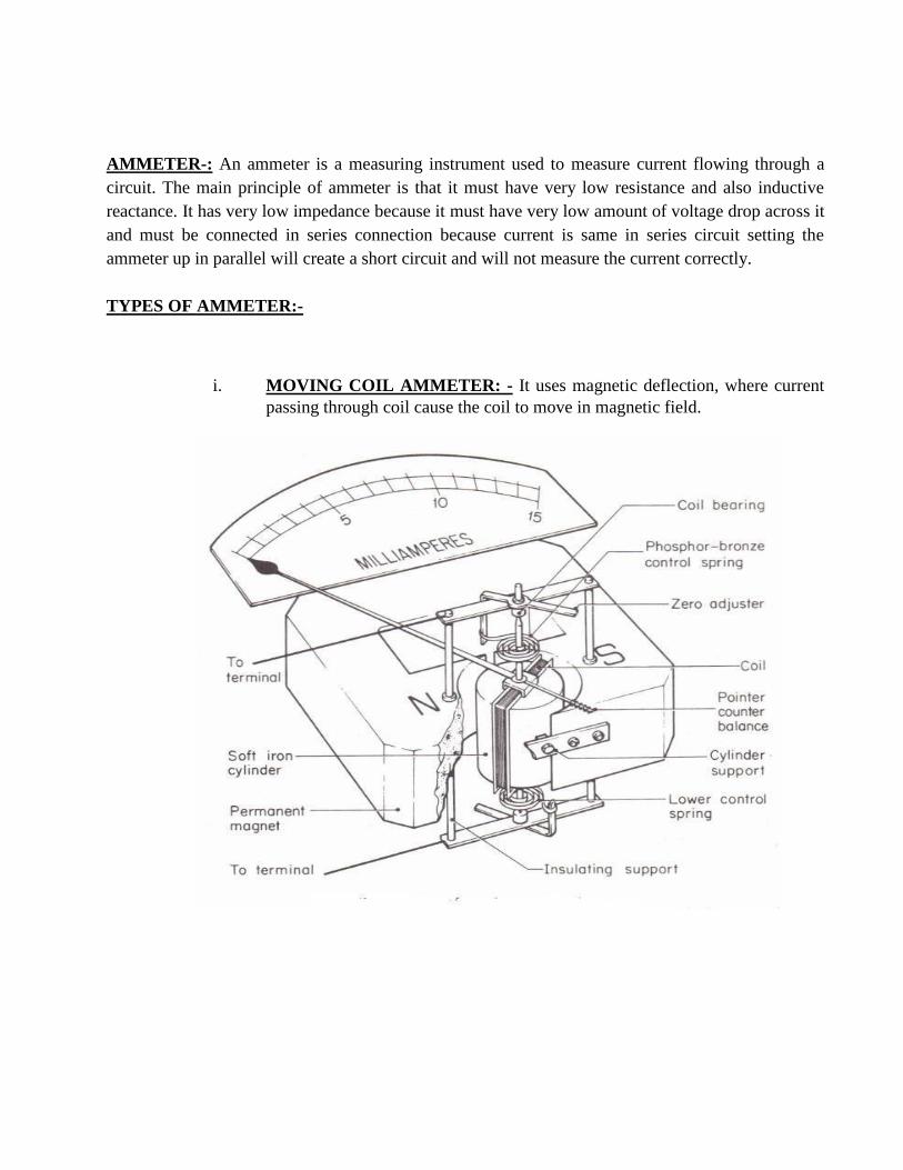
AMMETER-: An ammeter is a measuring instrument used to measure current flowing through a
circuit. The main principle of ammeter is that it must have very low resistance and also inductive
reactance. It has very low impedance because it must have very low amount of voltage drop across it
and must be connected in series connection because current is same in series circuit setting the
ammeter up in parallel will create a short circuit and will not measure the current correctly.
TYPES OF AMMETER:-
i. MOVING COIL AMMETER: - It uses magnetic deflection, where current
passing through coil cause the coil to move in magnetic field.

ELECTRODYNAMIC AMMETER:- An electrodynamic movement uses an electromagnet instead of
permanent magnet.
MOVING IRON AMMETER:- Moving iron ammeter uses a piece of iron which moves when acted
upon by electromagnetic force of a fixed coil of wire.

B. VOLTMETER:- The instrument which measures the voltage or potential difference in volts.
Voltmeter is always connected in parallel because if it is connected in series with the circuit it
minimize the current which flows, also in parallel potential remain same and having high resistance.
Voltmeter works on the principle of ohm‟s law, which states that the voltage across a resistance is a
directly proportional to the current passing through it.
C. WATTMETER:- Wattmeter is an instrument for measuring the electric power ( or the supply
rate of electrical energy) in „watts‟ ,of any given circuit. Electromagnetic wattmeter are used for
measurements of utility frequency and audio frequency power, other types are required for radio
frequency measurements.This work by using three coils, two fixed in series with the electrical load
and a moving coil in parallel with it. The series coil measure current flowing through the circuit and
the parallel coils measure voltage. It is situated between the two fixed coils and is attached to an
indicator needle
Types of Wattmeter
1. Dynamometer type Wattmeter
2. Induction type Wattmeter

D. (RESISTOR) OHMMETER:-A Resistor is a passive two terminal electrical component
that implement electrical resistance at a circuit element. Resistor are used to reduce
current flow adjust signal levels, to divide voltage & terminate transmission lines, the
value of resistance measured by ohm-meter. It can be connected in both series and
parallel.
E. CAPACITOR:-A Capacitor is a passive two terminal electronic component that stores
electrical energy in form of electric field. The plates accumulate electric charge when
connected to power source one plate accumulates position charge & the other plate
accumulates negative charge. The capacitance is the amount of electric charge i.e. stored
in the capacitor at a voltage of 1 volt. The capacitance is measured in units of farad (F).
The capacitor disconnects current in alternating current (AC) circuits.
F. INDUCTOR: -An inductor is a passive electronic component that stores energy in the
form of magnetic field. An inductor consists of wire loop or coil. Inductor can be used in
motors by creating mechanical energy from its electrical and magnetic energy. Inductor
blocks AC by allowing DC to flow because it only resists the change in current. The
growth of current flowing through the inductor is not instant but it is determined by
inductors on self-induced or back emf value. In inductor current will lack the voltage by
full 90 degree. Since there is no active energy involved or no work is done so power
factor will always be 0.
G. FUNCTION GENERATOR
A function generator is usually a piece of electronic list equipment or software used to
generate different types of electrical wave form over a wide range of frequencies. Most
function generator allows us to generate line, square or triangular AC function signals.
Function generator creates a change in voltage under some function of time. It is used for
testing the response of circuits to the common place input signals, produces various
voltage pattern at different frequencies and amplitude.
H. MULTIMETER
A multimeter is a multiplex also known as VOM (volt-ohm-milliammeter) is an electronic
measuring instrument that combines several measurement functions in one unit. A typical
multimeter can measure voltage, current and resistance. Analog multimeter uses a
micrometer with a moving pointer to display rating. Digital millimeters‟ are now for more
common due to their lower cost and more accuracy, but analog multimeter are still
preferable in some cases. A multimeter can be a handheld device useful for basic fault
finding and field service work or a bench

EXPERIMENT NO. 2
AIM:To verify KCL and KVL.
APPARATUS: DC network kit and connecting wires.
THEORY: KCL and KVL are used to solve the electrical networks
KCL: It states that in any electrical network the algebraic sum of currents meeting at a point is zero. Consider the case of few conductors meeting at a point A in the fig. Assuming incoming
currents to be positive and the outgoing currents to be negative.
Incoming current=outgoing current
KVL:It states that the algebraic sum of product of current and resistance in each of the conductorsin
any closed path in a network plus the algebraic sum of the e.m.f. in the closed path is zero.
ΣIR+ΣE.M.F.=0

CIRCUIT DIAGRAM:
PROCEDURE :
KCL: 1. Make the connection according to the ckt diagram
2. Set the three rheostats to their max value.
3. Switch on the power supply
4. Change the setting of the rheostats to get different readings in all the three ammeters.
5. Measure the current in the three ammeters
6. Check that at every time current in the main branch is equal to the sum of currents in the
two branches. repeat the setting of the rheostat
7. Switch off the power supply.
KVL: 1. Connect the circuit as per the circuit diagram
2. Switch on the power supply
3. Note down the readings of the voltmeters
4. Change the value of the rheostat and repeat the step several times and switch off the
power supply.
OBSERVATION TABLE:
KCL:
SR.NO. APPLIED I1 I2 I Il=I1+I2 REMARK
VOLTAGE (mA) (mA) (mA) (mA)
(volts)
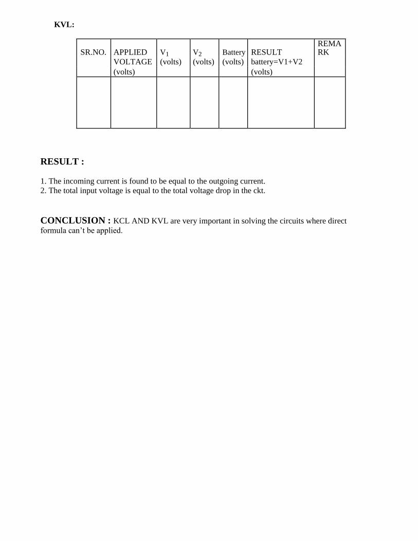
KVL:
SR.NO. APPLIED V1 V2 Battery RESULT REMARK
VOLTAGE (volts) (volts) (volts) battery=V1+V2
(volts) (volts)
RESULT : 1. The incoming current is found to be equal to the outgoing current.
2. The total input voltage is equal to the total voltage drop in the ckt.
CONCLUSION : KCL AND KVL are very important in solving the circuits where direct
formula can‟t be applied.

QUESTIONS/ANSWERS:
Q.1 What is the statement of Kirchhoff’s first law? A. The sum of the currents entering at any junction is equal to the sum of the currents
leaving the junction.
Q.2 According to Kirchhoff’s second law, the algebraic sum of all IR drops and emf’s
in any closed loop of a network is equal to…
A. It is equal to zero.
Q.4 What is the internal resistance of an ideal voltage source?
A. Zero.
Q.5 What is higher , the terminal voltage or the emf?
A. The emf has higher value.
Q.6 What is he internal resistance of the current source ideally?
A. Infinity.
Q.7 What is the active network?
A. An active network is that which contains one or more than one sources of emf. or
current sources.
Q.8 What is the bilateral network?
A. It is the circuit whose properties are same in either direction.
Q.9 What is the difference between a node and a branch?
A. A node is a junction in the circuit where two or more than two circuit elements are
connected together. The part of the network, which lies between two junctions, is called branch.
Q.10 What is the non-linear circuit?
A. The circuit whose parameters change with the change in voltage and current is called
the non-linear circuit.

EXPERIMENT NO. 3
AIM: To verify Thevenin‟s theorem.
APPARATUS: DC network kit and connecting wires.
THEORY: Thevenin's theorem as applied to the dc network circuit may be stated as the
current flowing through a load resistance RL connected across any two terminals A and B of
a linear bilateral network is given by VTH / RTH+RL where VTH is the open circuit voltage
and RTH is the internal resistance of the network from terminal A to B with all voltage sources replaced with their internal resistances and current sources with infinite resistance.
CIRCUIT DIAGRAM:
Find current in RL
STEP I Open circuit RL, Find Vth
STEP II Find Rth

STEP III
PROCEDURE:
1. To find the current flowing through the load resistance RL as shown in fig. remove RL
from the circuit temporarily and leave the terminals A and B open circuited. 2. Calculate the open circuit voltage VTH which appears across terminal A and B.
VTH = I.RTH This is called Thevenin‟s voltage.
3. Now calculate RTH=R1 R2 /R1+R2. This is called Thevenin‟s resistance.
4. Calculate IL= VTH/(RL+RTH). 5. VTH= E R2/R1+R2
OBSERVATION TABLE:
SR.NO APPLIED VTH VTH RTH IL IL RESULT VOLTAGE (volts) (volts) (Ohms) (mA) (mA)
(volts) Theo. Pract. Pract. Theo.
RESULT: Thevenin's theorem has been verified.
CONCLUSION: In Thevenin‟s equivalent circuit Thevenin‟s equivalent voltage is in series
with Thevenin‟s resistance and the load resistance.
.

QUESTIONS/ANSWERS: Q.1 To what type of circuit Thevenin‟s theorem is applicable A. Linear and bilateral Q.2 What is the use of Thevenin‟s theorem? A. To convert the complex ckt into a voltage source and a series resistance
Q.3 How RTH is connected with the ckt? A. In series
Q.4 How is RTH connected with the load resistance? A. In series Q.5 What modification is done in galvanometer to convert it into a ammeter?
A. A large resistance in parallel Q.6 What modification is done in the galvanometer to convert it into a voltmeter?
A. A series resistance Q.7 Resistance is an active element or the passive? A. Passive
Q.8 How will you calculate the RTH?
A. The resistance between the two terminals
Q.9 In place of current source, what is placed while calculating RTH? A. Replace current source by open ckt Q.10 In place of voltage source which electrical parameters is placed? A. A short ckt.


EXPERIMENT NO. 4
AIM: To verify Norton's theorem.
APPARATUS: DC network kit and connecting wires.
THEORY: Norton‟s theorem replaces the electrical network by an equivalent constant currentsource
and a parallel resistance. Norton‟s equivalent resistance RN=R1*R2/R1+R2 Actual load current in the
circuit IL1 Theoretical load current IL2=ISC*RN/(RN+RL), ISC is the short circuit current.
CIRCUIT DIAGRAM:
Find current in RL
STEP I Short circuit RL and Find current in AB
STEP II Find RN
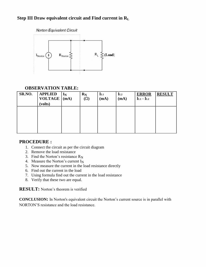
Step III Draw equivalent circuit and Find current in RL
OBSERVATION TABLE:
PROCEDURE : 1. Connect the circuit as per the circuit diagram
2. Remove the load resistance
3. Find the Norton‟s resistance RN 4. Measure the Norton‟s current IN 5. Now measure the current in the load resistance directly
6. Find out the current in the load
7. Using formula find out the current in the load resistance
8. Verify that these two are equal.
RESULT: Norton‟s theorem is verified
CONCLUSION: In Norton's equivalent circuit the Norton‟s current source is in parallel with
NORTON‟S resistance and the load resistance.
SR.NO. APPLIED IN RN IL1 IL2 ERROR RESULT
VOLTAGE (mA) (Ω) (mA) (mA) IL1 - IL2
(volts)

QUESTIONS/ANSWERS: Q.1 To what type of network Norton‟s theorem applicable? A. Two terminal linear network containing independent voltage and current sources.
Q.2 How is RN connected to IN? A. In the parallel
Q.3 What is placed in place of voltage sources while calculating the RN?
A. Their internal resistance replaces these. Q.4 Give an example of unilateral ckt? A. Diode rectifier Q.5 What is unilateral ckt? A. Whose characteristics changes with the change in direction of operation Q.6 Give one example of the bilateral n/w? A. Transmission lines
Q.7 What is the limitation of Ohm‟s law? A. Provided physical conditions do not change Q.8 What is the reason that ground pin are made of greater diameter in the plugs?
A. R=ρL/A Q.9 Where is the voltage divider rule applicable? A. Two resistance in series Q.10 Where is the current divider rule applicable
A. When there are two resistances in parallel

EXPERIMENT NO. 5
AIM: To verify superposition theorem.
APPARATUS: Digital multi-meter, power supply, resistance (wire wound), Connecting
Wires
THEORY: Superposition theorem states that in a linear network containing several
independent sources, the overall response at any point in the network equals the sum of
responses due to each independent source considered separately with all other independently
sources made inoperative(short circuited). To make a source inoperative, it is short circuited
leaving behind its internal resistance if it is a voltage source, and it is open circuited leaving
behind its internal resistance if it is a current source.In most electrical circuit analysis problems,
a circuit is energized by a single independent energy source. In such cases, it is quite easy to find
the response (i.e., current, voltage, power) in a particular branch of the circuit using simple
network reduction techniques (i.e., series parallel combination, star delta transformation,
etc.).However, in the presence of more than one independent source in the circuit, the response
cannot be determined by direct application of network reduction techniques. In such a situation,
the principle of superposition may be applied to a linear network, to find the resultant response
due to all the sources acting simultaneously.
The superposition theorem is based on the principle of superposition. The
principle of Superposition states that the response (a desired current or the voltage) at any point
in the linear network having more than one independent source can be obtained as the sum of
responses caused by the separate independent sources acting alone. The validity of principle of
superposition means that the presence of one excitation sources does not affect the response due
to other excitations.

CIRCUIT DIAGRAM:
PROCEDURE:
1. Connect the DC power supply to resistance R1.Adjust voltage of supply to E1=10V.
2. Connect another DC supply to resistance R2. Adjust voltage to E2=5 V.
3. Connect the DC ammeter(mA) to resistance R3.
4. Now remove the left hand side of supply and measure and record the current through R3.
I3‟‟=___ma
5. Remove another supply and measure and record the current through R3.
I3‟=__ma.
6. Now apply both the supplies and measure the current in R3 i.e. I3‟‟.
Now I3= I3‟‟+ I3‟
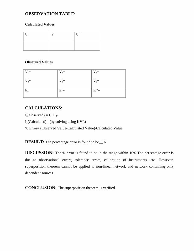
OBSERVATION TABLE:
Calculated Values
I3 I3‟ I3‟‟
Observed Values
V1=
V2=
V2=
V1=
V1=
V2=
I3= I3‟= I3‟‟=
CALCULATIONS:
I3(Observed) = I3‟+I3‟
I3(Calculated)= (by solving using KVL)
% Error= (Observed Value-Calculated Value)/Calculated Value
RESULT: The percentage error is found to be__%.
DISCUSSION: The % error is found to be in the range within 10%.The percentage error is
due to observational errors, tolerance errors, calibration of instruments, etc. However,
superposition theorem cannot be applied to non-linear network and network containing only
dependent sources.
CONCLUSION: The superposition theorem is verified.

QUESTION/ANSWERS:
1. What are the advantages and disadvantages of using superposition Theorem?
2. Why superposition theorem is not applied to non-linear circuits
3. Can superposition theorem be applied to circuit having A.C sources? If yes, then what will be
its requirements? 4. How can superposition theorem be applied to network containing both independent and dependent sources?

EXPERIMENT NO. 6
AIM: To study frequency response of series R-L-C circuit and determine resonance
frequency.
APPARATUS REQUIRED: CRO, Audio frequency generator, Multimeter and
connecting wires.
THEORY: In the series resonance circuit , the net reactance
X=XL-XC So impedance of the circuit is
Z=√(R2+ (XL-XC )
2)
at the resonance frequency the capacitive reactance becomes equal to the inductive reactance.
XL =XC
w0L=1/w0C
f0=1/2π√LC
CIRCUIT DIAGRAM:
PROCEDURE :
1. Make the connections shown in fig. 2. Frequency is given by audio frequency generator.
3. Change the frequency and note the reading carefully.
4. At certain frequency the voltage becomes maximum after which the voltage decreases.
This is the resonance frequency.
5. Plot a graph between frequency and voltage.

OBSERVATION TABLE:
S.NO FREQUENCY (KHz) CURRENT(AMP)
GRAPH:
C U
R
R
E
N T
fr FREQUENCY
RESULT : The resonance frequency is found to be……kHz
CONCLUSION: Impedance is minimum at resonance frequency.

QUESTIONS/ANSWERS: Q.1 If frequency is 50 Hz, what is the angular frequency? A. W=2πf =100π
Q.2 If time period is 1/50 sec, what is the frequency? A. f=1/T=50Hz
Q.3 If I=200sin 100πt, at which time it will have the value of 100A? A. 100=200sin
1/2=sin 100πt
100πt=π/6 t=1/600sec Q.4 What is the average value of a square wave of peak value 200V? A. 200V Q.5 What is the relation between the max value and the average value of the square wave?
A. Both are same Q.6 What is the form factor?
A. RMS/average Q.7 What is the form factor for a sine wave? A. 1.11 Q.8 What is the impedance for a series resonance circuit? A. R Q.9 What is the condition for resonance in a series RLC circuit?
A. XL=XC Q.10 What is the quality factor?
A. Quality factor = fr/B.W.

EXPERIMENT NO. 7
AIM: To study frequency response of parallel R-L-C circuit and determine resonance
frequency.
APPARATUS: CRO, Audio frequency generator, Multi meters and connecting
wires.
THEORY: For the parallel R-L-C circuit IC=ILSinΦL IL=V/Z, Sin ΦL=XL/Z V/Z*XL /Z=V/XC
Or XL*XC=Z2
or L/C=Z2
L/C=R2 + XL
2
fo=1/2π* √1/LC-R2/L
2
CIRCUIT DIAGRAM:
PROCEDURE :
Make the connections shown in fig.
Frequency is given by audio frequency generator.
Change the frequency and note the reading carefully
At certain frequency the voltage becomes minimum after which the voltage
increases. This is the resonance frequency
Plot a graph between frequency and voltage.

OBSERVATION TABLE:
SR.NO FREQUENCY (KHz) CURRENT (AMP)
GRAPH:
C U
R
R
E
N T
fr FREQENCY
RESULT: The resonance frequency is found to be……kHz.
CONCLUSION: Impedance is maximum at resonance frequency

QUESTIONS/ANSWERS: Q.1 What is the power factor of the resistance ckt? A. Unity
Q.2 What is the power factor of the inductive or the capacitive ckt?
A. Zero
Q.3 What is the effect of the inductance on the time constant in any inductive ckt?
A. Increases with increase in inductance and decreases with decrease in R
Q.4 What is the effect of dc flow on the dc?
A. Only at the time of on and off
Q.5 Can all the laws of the dc be applied to the ac ckt having resistance?
A. Yes
Q.6 What is the time constant of the capacitive ckt?
A. RC
Q.7 What is the effect of length of iron path on inductance?
A. Inductance varies inversely as the length of iron path.
Q.8 If two signals having same frequency have opposite phase, what is the phase anglebetween
them?
A. 1800
Q.9 For least power consumption what should be the phase angle between current and voltage?
A. 900
Q.10 What is magnified by the parallel RLC ckt?
A. Current.

EXPERIMENT NO. 8
AIM: To study and plot the transient response of RL circuit
APPARATUS REQUIRED : Power Supply, Circuit Board Kit., CRO, Function Generator,
Connecting Leads.
INTRODUCTION: The Transient Response (also known as the Natural Response) is the way
the circuit responds to energies stored in storage elements, such as capacitors and inductors. If an
inductor has energy stored within it, then that energy can be dissipiated/absorbed by a resistor.
How that energy is dissipated is the transient Response.
CIRCUIT DIAGRAM:
THEORY : In an R-L circuit, voltage across the inductor decreases with time.
The expression for the current build-up across the Inductor is given by
where, V is the applied source voltage to the circuit for t ≥ 0. The response curve is increasing.
The expression for the current decay across the Inductor is given by:
The Time Constant, ( τ ) of the LR series circuit is given as L/R and in which V/R represents the
final steady state current value after five time constant values. Once the current reaches this

maximum steady state value at 5τ, the inductance of the coil has reduced to zero acting more like a
short circuit and effectively removing it from the circuit.
Since the voltage drop across the resistor, VR is equal to I*R (Ohms Law), it will have the same
exponential growth and shape as the current. However, the voltage drop across the
inductor, VL will have a value equal to: Ve(-Rt/L)
. Then the voltage across the inductor, VL will
have an initial value equal to the battery voltage at time t = 0 or when the switch is first closed and
then decays exponentially to zero as represented in the above curves.
The time required for the current flowing in the LR series circuit to reach its maximum steady state
value is equivalent to about 5 time constants or 5τ. This time constant τ, is measured by τ = L/R,
in seconds, where R is the value of the resistor in ohms and L is the value of the inductor in
Henries. This then forms the basis of an RL charging circuit were 5τ can also be thought of as
“5*(L/R)” or the transient time of the circuit.
PROCEDURE:-
a) Connect the circuit according to the fig. & switch 'ON' the Supply.
b) Feed square wave from function generator to the I/P terminal of the circuit
c) Connect the CRO to the O/P terminal & note down the O/P wave.
d) Draw the Input & Output wave on the graph paper.
\
RESULT/CONCLUSIONS: Transient response of RL circuit has been studied and the
results obtained are shown on the graph.
PRECAUTIONS :
a) Make the connections according to the circuit diagram. Power supply should be switched

off.
b) Connections should be tight.
c) Handle the CRO carefully.
d) Note the readings carefully.
QUESTIONS/ANSWERS:
Q1 Define transient and steady state response of system.
Ans. The voltage or current are changed from one transient state to another transient state is called
transient response. The behaviour of voltage or current does not change with time is called steady
state response.
Q2 Define natural response and forced response of a system.
Ans. The response determined by the internal energy stored in the network is called natural
response. It depends upon the type of elements, their size and the interconnection of elements. The
response is independent of the source. Energy may be stored internally in the form of electric field
of capacitor or in the magnetic field of an inductor.
The natural response also known as transient response. The response determined by the application
of external energy source is called forced response. The external energy source of forcing function
may be direct voltage or current, sinusoidal source, exponential function, ramp function.
Q3. Why transient occurs in electric circuits?
Ans. The inductance will not allow the sudden change in current and the capacitance will not allow
sudden change in voltage. Hence inductive and capacitive circuits (or in general reactive
circuits0transient occurs during switching operation.
Q4. Define time constant of RL circuit.
Ans. The time constant of RL circuit is defined as the ratio of inductance and resistance of
the circuit.

EXPERIMENT NO. 9
AIM:-To study and plot the transient response of RC circuit.
APPARATUS REQUIRED : Power Supply, Circuit Board Kit., CRO, Function Generator,
Connecting Leads.
BRIEF THEORY : A capacitor has the ability to store an electrical charge and energy. The
voltage across the capacitor is related to the charge by the equation V=Q/C for steady state values,
or expressed as an instantaneous value, dv=dq/C
By definition i = dq/dt or dq = idt. Therefore
The derivation of the transient responses of both the capacitor current and voltage in an RC circuit
when a source voltage is suddenly applied to that circuit is shown below. Note that the time
constant (t = τ = RC). The step response of an RC circuit can be analyzed using the following
circuit:
Immediately after the switch closes, KVL requires thatIf we differentiate (1) with respect to t, we
get

The other two terms drop out because they are constants. Now divide thru by R-
The voltage across the capacitor at t = 0 (Vo) will be zero because there cannot be an instantaneous
change in voltage across the capacitor. Therefore, the initial current in the circuit will be as follows
Normalized current = i(t)/Io ,versus Normalized time = t/RC.
Note that the time constant (t = τ = RC) occurs at 36.8% of Io or 0.368 Vs/R. We also know that

Substituting i from (7) and Io from (8) into (9), Putting in limits and simplifying gives:
Plotting normalized voltage ( Vc /VS ) versus normalized time ( t/RC )
Note that the time constant (t = τ = RC) occurs at 0.632 Vs
PROCEDURE :
a) Connect the circuit according to the fig. & switch 'ON' the supply.
b) Feed square wave from function generator to the Input terminal of the circuit.
c) Connect the CRO to the O/P terminal & note down the O/P wave
d) Draw the Input & Output wave on the graph paper.

RESULT/CONCLUSIONS: Transient response of RC circuit has been studied and the results
obtained are shown on the graph.
DISCUSSION: The capacitor charges and discharges within one minute.
PRECAUTIONS :
a) Make the connections according to the circuit diagram. Power supply should be switched off.
b) Connections should be tight.
c) Handle the CRO carefully.
d) Note the readings carefully.
QUESTIONS/ANSWERS:
Q1. Define time constant of RC circuit.
Ans: The time constant of RC circuit is defined as the product of capacitance and resistance of the
circuit. The time constant of RC circuit is defined as the time taken by the voltage across the
capacitance to reach 63.21%of its final steady state value.
Q2. Voltage across capacitor cannot change instantaneously. Justify.
Ans:
If the voltage across capacitance changes instantaneously then the current IL=a ,which is
impossible since it requires infinite power. Hence voltage across capacitor cannot change
instantaneously.

EXPERIMENT NO. 10
AIM: To find the polarity and turns ratio of a single phase transformer.
APPARATUS: One transformer, two voltmeters, one autotransformer
THEORY:
It is essential to know the relative polarity at any instant of primary and secondary terminals
for making correct connections. When the two transformers are to be connected in parallel to
share the load on the system. The marking is correct if voltage E3 ( E1+E2 OR E1-E2 ) is less
than E1,such a polarity is termed as subtractive polarity. The standard practice is to have
subtractive polarity because it reduces the voltage stress between adjacent loads. In case E3 > E1
the emf induced in primary and secondary have additive relation and transformer is said to have
additive polarity.
CIRCUITDIAGRAM:

PROCEDURE:
Polaritytest:
- connect the circuit as shown in thediagram.
- Switch on the single phase a.c.supply.
- Record the voltages E1, E2 and E3 .In case E3<E1 polarity issubtractive.
- Repeat the step 3 after connecting terminals A1 and a2 .In case E3>
E1polarity is additive.
- Switch off the a.c.supply
Turn RatioTest:
- Connect the circuit as shown in thediagram.
- Switch on the a.c.supply.
- Record voltage E1 across primary and E2 across various tapping's
ofsecondary.
- If E1>E2 then transformer is stepdown.
- If E2> E1 then transformer is stepup.
- Switch off a.c.supply
OBSERVATIONTABLE:
SUBTRACTIVE-POLARITY:
ADDITIVE-POLARITY:
RESULT: If E2>E1 then transformer is step up otherwise stepdown.
S.NO. E1 E2 E3=E2-E1
S.NO. E1 E2 E3=E1+E2

EXPERIMENT NO. 11
Objective:
Speed control of DC shunt motor by armature voltage control method.
Apparatus Required:
S.No. Apparatus Range Type Quantity
Circuit Diagram:
Theory:
The armature voltage control method of speed control of DC shunt motor is used for
controlling speed below base speed. As its used for below base speed hence its also called as
constant torque control method as our torque remains constant in this region. This method is
used when speeds below the no-load speed are required. As the supply voltage is normally
constant, the voltage across the armature is varied by inserting a variable rheostat in series
with the armature circuit. As controller resistance is increased, voltage across the armature is
decreased, thereby decreasing the armature speed. For a load constant torque, speed is
approximately proportional to the voltage across the armature.
N = K{V-Ia. (Ra+R)}/ Flux
Procedure:
1. Connections are made as per the circuit diagram.
2. After checking the maximum position of armature rheostat and minimum position of field rheostat, DPST switch is closed

Armature Control:
Field current is fixed to various values and for each fixed value, by varying the armature
rheostat, speed is noted for various voltages across the armature.
Observation Table:
Armature Voltage Control:
Va =
S.No. Field Speed
Current N (rpm)
If (A)
Result: Thus we have been obtained the speed control characteristic curve of DC Shunt
motor.
Precautions:
1. Field Rheostat should be kept in the minimum resistance position at the time of starting and stopping the motor.
2. Armature Rheostat should be kept in the maximum resistance position at the time of starting and stopping the motor

EXPERIMENT NO. 12
Objective- Speed control of DC shunt motor by field current control method.
Apparatus Required:
S.No. Apparatus Range Type Quantity
Circuit Diagram:
Theory:
Speed control of DC shunt motor by the help of field flux control is carried out above the
base speed. As its used for above base speed hence its also called as constant power control
method as our power remains constant in this region By decreasing the flux, the speed can be
increased and vice versa. The flux of a dc motor can be changed by changing Ish with help of
a shunt field rheostat. Since Ish is relatively small, shunt field rheostat has to carry only a
small current, which means IshR loss is small, so that rheostat is small in size.
Procedure:
1. Connections are made as per the circuit diagram.
2.After checking the maximum position of armature rheostat and minimum position of field rheostat, DPST switch is closed.

Field Control:
1. Armature voltage is fixed to various values and for each fixed value, by adjusting the field rheostat, speed is noted for various field currents.
2. Bringing field rheostat to minimum position and armature rheostat to maximum position DPST switch is opened.
Observation Table:
Field Control:
Va =
S.No. Field current (A) Speed N (rpm)
Result:
Thus we have been obtained the speed control characteristic curve of DC Shunt motor.
Precautions:
1. Field Rheostat should be kept in the minimum resistance position at the time of starting and stopping the motor.
2. Armature Rheostat should be kept in the maximum resistance position at the time of starting and stopping the motor.

EXPERIMENT NO. 13
AIM: To study the constructional features and working of three phase induction motor.
CONSTRUCTION:
Stator:
It is stationary part of induction motor.It consists stator winding.It is housed on the motor frame.
It is made from casting materials.
Rotor:
It is the rotating part of the induction motor. It is housed on the shaft of induction motor. It has
two ends, one is called driving end and another is called non driving end. Mechanical load is
connected on driving end while cooling fan is connected on non-driving end. Both the ends are
connected with bearings for free rotation means of reduced friction losses.
Stator Windings:
1.Star connected
2. Delta connected.
Rotor Windings:
It is wound as rotor bars and short circuited at both the ends through end rings.
According to rotor construction it can be classified
1. Squirrel cage induction motor.
2. Slip ring induction motor.
CUT VIEW OF 2 PHASE INDUCTION MOTOR:

Working of Three Phase Induction Motor:
1. Production of Rotating Magnetic Field
The stator of the motor consists of overlapping winding offset by an electrical angle of 120°.
When the primary winding or the stator is connected to a 3 phase AC source, it establishes a
rotating magnetic field which rotates at the synchronous speed.
2. Secrets Behind the Rotation
According to Faraday‟s law an emf induced in any circuit is due to the rate of change of
magnetic flux linkage through the circuit. As the rotor winding in an induction motor are either
closed through an external resistance or directly shorted by end ring, and cut the stator rotating
magnetic field, an emf is induced in the rotor copper bar and due to this emf a current flows
through the rotor conductor. Here the relative speed between the rotating flux and static rotor
conductor is the cause of current generation; hence as per Lenz's law the rotor will rotate in the
same direction to reduce the cause i.e. the relative velocity.
Thus from the working principle of three phase induction motor it may observed that the
rotor speed should not reach the synchronous speed produced by the stator. If the speeds equals,
there would be no such relative speed, so no emf induced in the rotor, & no current would be
flowing, and therefore no torque would be generated. Consequently the rotor cannot reach the
synchronous speed. The difference between the stator (synchronous speed) and rotor speeds is
called the slip. The rotation of the magnetic field in an induction motor has the advantage that no
electrical connections need to be made to the rotor.
Thus the three phase induction motor is:
Self-starting.
Less armature reaction and brush sparking because of the absence of commutators and
brushes that may cause sparks.
Robust in construction.
Economical.
Easier to maintain.
Induction motor is also called asynchronous motor as it runs at a speed other than the
synchronous speed. Like any other electrical motor, induction motor have two main parts namely
rotor and stator.

EXPERIMENT NO. 14
AIM: To study the constructional features and working of DC motor.
CONSTRUCTION:
YOKE: It supports the entire machine and acts as protective cover, supports the poles.It
offers flux path completion through it. Therefore it should be good
ferromagneticmaterial. In large machine yoke are made of cast steel. When DC machine
operate withpower electronic converter & control system application, laminated yokes
are preferred
ARMATURE CORE: To reduces the eddy current we laminate the core or putting
silicon in steel called "Stalloy" or electrical steel in 3.5% to 4%.
COMMUTATOR: It is madeup of hard drawn copper and insulated by "Mica". It is a
rotating switch which converts AC into DC. The thickness of insulation is 0.8mm.
BRUSHES: These are stationary sliding contacts which offer a good electrical
connection between rotating commentator and stationary loads.
SHAFT: The armature core and commentator are mount and keyed to the shaft for the
exchanged of mechanical power.

CUT VIEW OF DC MACHINE:
THEORY: Electrical motors are everywhere around us. Almost all the electro-mechanical
movements we see around us are caused either by a AC or a DC motor. Here we will be
exploring DC motors. This is a device that converts DC electrical energy to a mechanical energy.
Principle of DC Motor:
Direct current motor works on the principle, when a current carrying conductor is placed in a
magnetic field, it experiences a torque and has a tendency to move. This is known as motoring
action. If the direction of current in the wire is reversed, the direction of rotation also reverses.
When magnetic field and electric field interact they produce a mechanical force, and based on
that the working principle of DC motor is established.
The direction of rotation of a this motor is given by Fleming‟s left hand rule, which states that if
the index finger, middle finger and thumb of your left hand are extended mutually perpendicular
to each other and if the index finger represents the direction of magnetic field, middle finger
indicates the direction of current, then the thumb represents the direction in which force is
experienced by the shaft of the dc motor.
The back emf like in case of a generator is represented by

Where, P = no of poles
φ = flux per pole
Z= No. of conductors
A = No. of parallel paths
and N is the speed of the DC Motor.
So, from the above equation we can see Eb is proportional to speed „N‟. That is whenever a direct
current motor rotates, it results in the generation of back Emf. Now lets represent the rotor speed
by ω in rad/sec. So Eb is proportional to ω.
So, when the speed of the motor is reduced by the application of load, Eb decreases. Thus the
voltage difference between supply voltage and back emf increases that means E − Eb increases.
Due to this increased voltage difference, armature current will increase and therefore torque and
hence speed increases. Thus a DC Motor is capable of maintaining the same speed under variable
load.
Now armature current Ia is represented by
Now at starting, speed ω = 0 so at starting Eb = 0.
Now since the armature winding Ra is small, this motor has a very high starting current in the
absence of back Emf. As a result we need to use a starter for starting a DC Motor. Now as the
motor continues to rotate, the back Emf starts being generated and gradually the current
decreases as the motor picks up speed.

EXPERIMENT NO. 15
AIM:To study the constructional features and working of synchronous motor.
CONSTRUCTION:
CUT VIEW OF SYNCHRONOUS MACHINE:
Stator:
It provides mechanical support to the stator and and rotor.It is made from casting materials.It is
stationary part of induction motor.It consists stator winding.It is housed on the motor frame.
Rotor:
Rotor can be classified into two types.
1. Salient Pole type
2. Cylindrical type
Construction of the two are shown in the below given figure.

Salient pole type
In salient pole type air gap is minimum along d axis and maximum along q axis.It contains large
diameter and small length also known as hydro electric type.
Cylindrical type
Air gap is uniform throughout the surface. It contains large length small diameter also known
as Turbo electric type.
Slip rings ( Brushes):
It is made of condcutive material. Mostly graphite is used.
THEORY: Electrical motor in general is an electro-mechanical device that converts energy
from electrical domain to mechanical domain. Based on the type of input we have classified it
into single phase and 3 phase motors. Among 3 phase induction motors and synchronous
motors are more widely used. When a 3 phase electric conductors are placed in a certain
geometrical positions (In certain angle from one another) then an electrical field is generated.
Now the rotating magnetic field rotates at a certain speed, that speed is called synchronous
speed. Now if an electromagnet is present in this rotating magnetic field, the electromagnet is
magnetically locked with this rotating magnetic field and rotates with same speed of rotating
field.
Synchronous motors is called so because the speed of the rotor of this motor is same as the
rotating magnetic field. It is basically a fixed speed motor because it has only one speed, which
is synchronous speed and therefore no intermediate speed is there or in other words it‟s in
synchronism with the supply frequency. Synchronous speed is given by
where , f = supply frequency & p = no. of poles

Normally it's construction is almost similar to that of a 3 phase induction motor, except the fact
that the rotor is given dc supply, the reason of which is explained later. Now, let us first go
through the basic construction of this type of motor
From the above picture, it is clear that how this type of motors are designed. The stator is given
is given three phase supply and the rotor is given dc supply.
Main Features of Synchronous Motors:
1. Synchronous motors are inherently not self starting. They require some external
means to bring their speed close to synchronous speed to before they are
synchronized.
2. The speed of operation of is in synchronism with the supply frequency and hence for
constant supply frequency they behave as constant speed motor irrespective of load
condition
3. This motor has the unique characteristics of operating under any electrical power
factor. This makes it being used in electrical power factor improvement.
Principle of Operation Synchronous Motor:
Synchronous motor is a doubly excited machine i.e. two electrical inputs are provided to it. It‟s
stator winding which consists of a 3 phase winding is provided with 3 phase supply and rotor is
provided with DC supply. The 3 phase stator winding carrying 3 phase currents produces 3 phase
rotating magnetic flux. The rotor carrying DC supply also produces a constant flux. Considering
the frequency to be 50 Hz, from the above relation we can see that the 3 phase rotating flux
rotates about 3000 revolution in 1 min or 50 revolutions in 1 sec. At a particular instant rotor and
stator poles might be of same polarity (N-N or S-S) causing repulsive force on rotor and the very
next second it will be N-S causing attractive force. But due to inertia of the rotor, it is unable to
rotate in any direction due to attractive or repulsive force and remain in standstill condition.
Hence it is not self starting.
To overcome this inertia, rotor is initially fed some mechanical input which rotates
it in same direction as magnetic field to a speed very close to synchronous speed. After some
time magnetic locking occurs and the synchronous motor rotates in synchronism with the
frequency.
Methods of Starting of Synchronous Motor:
1. Motor starting with an external prime Mover : Synchronous motors are
mechanically coupled with another motor. It could be either 3 phase induction motor
or DC shunt motor. DC excitation is not fed initially. It is rotated at speed very close
to its synchronous speed and after that DC excitation is given. After some time when
magnetic locking takes place supply to the external motor is cut off.

2. Damper winding : In case, synchronous motor is of salient pole type, additional
winding is placed in rotor pole face. Initially when rotor is standstill, relative speed
between damper winding and rotating air gap flux in large and an emf is induced in it
which produces the required starting torque. As speed approaches synchronous speed ,
emf and torque is reduced and finally when magnetic locking takes place, torque also
reduces to zero. Hence in this case synchronous is first run as three phase induction
motor using additional winding and finally it is synchronized with the frequency.
Application of Synchronous Motor:
1. Synchronous motor having no load connected to its shaft is used for power factor
improvement. Owing to its characteristics to behave at any electrical power factor, it
is used in power system in situations where static capacitors are expensive.
2. Synchronous motor finds application where operating speed is less (around 500 rpm)
and high power is required. For power requirement from 35 kW to 2500 KW, the size,
weight and cost of the corresponding three phase induction motor is very high.


