BEE MANUALS 1 - G H Raisoni College Of Engineering...
32
DEPARTMENT OF ELECTRICAL ENGINEERING I st YEAR B.E. G.H.RAISONI COLLEGE OF ENGINEERING, NAGPUR 1 G.H.RAISONI COLLEGE OF ENGINEERING FIRST YEAR B.E. BASIC ELECTRICAL ENGG. LAB INDEX Sr. No. Name of Experiment Page No. 01 To Verify KVL & KCL 02 02 To Verify Superposition Theorem 07 03 To Determine R And L Of Choke Coil 11 04 To Plot B-H Curve Of Magnetic Material 13 05 To Plot Vector Diagram Of R-L-C Series Circuit 16 06 To Find Efficiency And Regulation Of Single Phase Transformer By O/C & S/C Test 19 07 Verification Of Line Voltage And Phase Voltage In Three Phase Star Connected Balanced Load 24 08 To Observe Reversal Of Three Phase Induction Motor 27 09 Speed Control Of Dc Shunt Motor 29
-
Upload
dinhnguyet -
Category
Documents
-
view
218 -
download
3
Transcript of BEE MANUALS 1 - G H Raisoni College Of Engineering...

DEPARTMENT OF ELECTRICAL ENGINEERING Ist YEAR B.E.
G.H.RAISONI COLLEGE OF ENGINEERING, NAGPUR 1
G.H.RAISONI COLLEGE OF ENGINEERING
FIRST YEAR B.E.
BASIC ELECTRICAL ENGG. LAB
INDEX
Sr.
No.
Name of Experiment Page
No.
01 To Verify KVL & KCL
02
02 To Verify Superposition Theorem
07
03 To Determine R And L Of Choke Coil
11
04 To Plot B-H Curve Of Magnetic Material
13
05 To Plot Vector Diagram Of R-L-C Series Circuit
16
06 To Find Efficiency And Regulation Of Single
Phase Transformer By O/C & S/C Test
19
07 Verification Of Line Voltage And Phase Voltage
In Three Phase Star Connected Balanced Load
24
08 To Observe Reversal Of Three Phase Induction
Motor
27
09 Speed Control Of Dc Shunt Motor
29

DEPARTMENT OF ELECTRICAL ENGINEERING Ist YEAR B.E.
G.H.RAISONI COLLEGE OF ENGINEERING, NAGPUR 2
Experiment No:-01
KIRCHOFF’S ( KCL & KVL ) LAWS
OBJECTIVES :
1. To study Kirchoff’s Current Law ( KCL) 2. To study Kirchoffs Volatge Law .( KVL)
EQUIPMENTS REQUIRED : DC Voltmeter (0 -75), Digital Multimeter Ammeter (1-0-1 mA) 3 No. COMPONENT USED:-
R1=150Ω , R2=100Ω, R5 =150Ω, R3=120Ω CIRCUIT DIAGRAM:-
A A
A
+
-
S1
1 2
R2I1
I3
I2
R3
1 2
+
-
R1
VR1 VR2
(I1+I2)
S2
R4
VR3 VR4
s4S3
OFF ON
V1
R5VR5
V2
B
THEORY:- In many circuits , in which various components are used are in either parallel , in series , or in series parallel for example , a circuit with two or more batteries connected in its different branches . Another example is an unbalanced bridge circuit. Hence rules o series & parallel circuits are not applicable. Such circuits can be easily solved with help of kirchoffs law which are as follows.
1. Kirchoff’s current Law 2. Kirchoff’s voltage law.

DEPARTMENT OF ELECTRICAL ENGINEERING Ist YEAR B.E.
G.H.RAISONI COLLEGE OF ENGINEERING, NAGPUR 3
KIRCHOFF’S CURRENT LAW
It states that in any network of conductors, the algebraic sum of currents meeting at appoint (at a junction) is ‘0’ In other words, the total current leaving a junction is equal to the total current entering that point.
I5
I2I1
I3
I4
A
Fig.1
I1+I4=I2+I3+I5 Incoming signal + ve & outgoing signal – ve . Explanation:
Consider in case of 5 currents meeting at junction A of the network is shown in fig.1. All the currents entering the junction would be taken as positive where as those leaving is taken as –ve . Determination of algebraic sign
We will follow a very simple sign conversion which would apply equally to IR drop & battery emf’s . A rise (or increase) in voltage would be considered as +ve. & given and + ve sign & a fall (or decrease) in voltage would be considered -ve & hence given as - ve sign. Battery EMF
While going round a loop ( in a direction of our own choice ) if we go from the –ve terminal of battery to its +ve terminal , there is rise in potential , hence this EMF should be given as + ve signal .On the other hand if we go from its + ve terminal ti its –ve terminal , there’s a fall in potential , hence this battery EMF should be given as –ve sign . It is important to note that algebraic sign of battery EMF is independent of the direction of current flow. (Whether clockwise or in anticlockwise) through the branch which the battery is connected.
DEPARTMENT OF ELECTRICAL ENGINEERING Ist YEAR B.E.
G.H.RAISONI COLLEGE OF ENGINEERING, NAGPUR 4
IR drops in series.
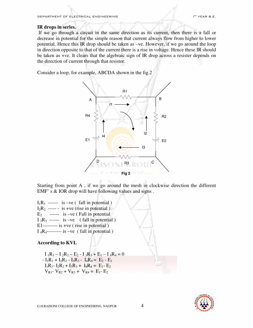
If we go through a circuit in the same direction as its current, then there is a fall or decrease in potential for the simple reason that current always flow from higher to lower potential. Hence this IR drop should be taken as –ve. However, if we go around the loop in direction opposite to that of the current there is a rise in voltage. Hence these IR should be taken as +ve. It clears that the algebraic sign of IR drop across a resister depends on the direction of current through that resistor. Consider a loop, for example, ABCDA shown in the fig.2
I1
R1
R2
R3
R4
E1 E2
D C
BA
Fig 2
I4I2
I3
Starting from point A , if we go around the mesh in clockwise direction the different EMF’ s & IOR drop will have following values and signs . I1R1 ------ is –ve ( fall in potential ) I2R2 ----- - is +ve (rise in potential ) E2 ------ is –ve ( Fall in potential I 3R3 ------ is –ve ( fall in potential ) E1--------- is +ve ( rise in potential ) I 4R4--------- is –ve ( fall in potential )
According to KVL
I 1R1 – I 2R2 – E2 - I 3R3 + E1 – I 4R4 = 0
- I1R1 + I2R2 - I3R3 - I4R4 = E2 - E1 I1R1- I2R2 + I3R3 + I4R4 = E1- E2 VR1- VR2 + VR3 + VR4 = E1- E2
DEPARTMENT OF ELECTRICAL ENGINEERING Ist YEAR B.E.
G.H.RAISONI COLLEGE OF ENGINEERING, NAGPUR 5
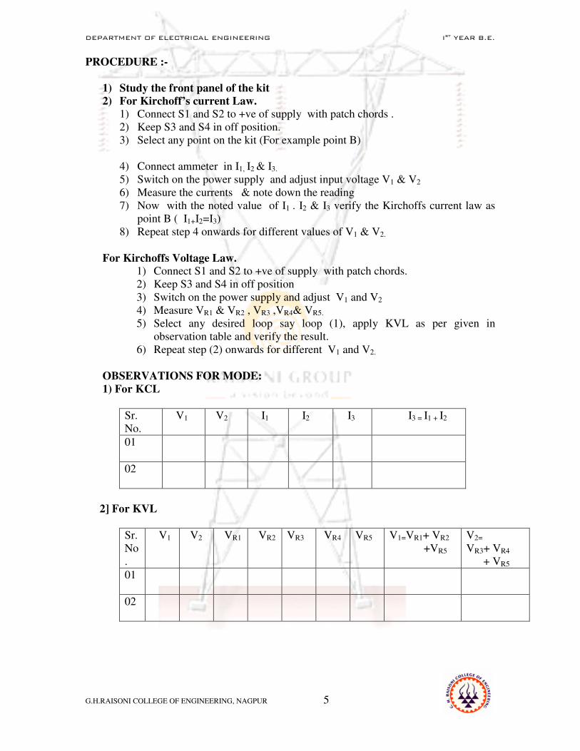
PROCEDURE :-
1) Study the front panel of the kit
2) For Kirchoff’s current Law.
1) Connect S1 and S2 to +ve of supply with patch chords . 2) Keep S3 and S4 in off position. 3) Select any point on the kit (For example point B) 4) Connect ammeter in I1, I2 & I3. 5) Switch on the power supply and adjust input voltage V1 & V2 6) Measure the currents & note down the reading 7) Now with the noted value of I1 . I2 & I3 verify the Kirchoffs current law as
point B ( I1+I2=I3) 8) Repeat step 4 onwards for different values of V1 & V2.
For Kirchoffs Voltage Law.
1) Connect S1 and S2 to +ve of supply with patch chords. 2) Keep S3 and S4 in off position 3) Switch on the power supply and adjust V1 and V2 4) Measure VR1 & VR2 , VR3 ,VR4& VR5. 5) Select any desired loop say loop (1), apply KVL as per given in
observation table and verify the result. 6) Repeat step (2) onwards for different V1 and V2.
OBSERVATIONS FOR MODE:
1) For KCL
Sr. No.
V1 V2 I1 I2 I3 I3 = I1 + I2
01
02
2] For KVL
Sr. No.
V1 V2 VR1 VR2 VR3 VR4 VR5 V1=VR1+ VR2
+VR5
V2=
VR3+ VR4 + VR5
01
02

DEPARTMENT OF ELECTRICAL ENGINEERING Ist YEAR B.E.
G.H.RAISONI COLLEGE OF ENGINEERING, NAGPUR 6
RESULT:-
The current approaching to the junction is equal to currents leaving from the junction. So KCL is verified similarly voltage supplied to desired loop equals to voltage drop by same loop so KVL is verified. DISCUSSION QUESTION:-
1.Difference between loop and Mesh. 2.What is open circuit and Short circuit? 3.What is the main difference while applying Kirchhoff’s Laws to d.c circuits and a.c circuits using meter readings? 4.What are the factors ignored in the calculations ?
DEPARTMENT OF ELECTRICAL ENGINEERING Ist YEAR B.E.
G.H.RAISONI COLLEGE OF ENGINEERING, NAGPUR 7
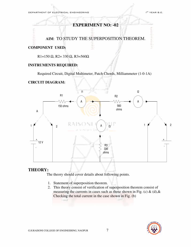
EXPERIMENT NO: -02
AIM: TO STUDY THE SUPERPOSITION THEOREM. COMPONENT USED:
R1=150 Ω, R2= 330 Ω, R3=560Ω
INSTRUMENTS REQUIRED:
Required Circuit, Digital Multimeter, Patch Chords, Milliammeter (1-0-1A) CIRCUIT DIAGRAM:
A A
A
12 V+
-
A
1 2
R1
150 ohms
I1
I3
I2
R2
R3330
ohms
560
ohms
1 2
+
-
THEORY: The theory should cover details about following points.
1. Statement of superposition theorem. 2. This theory consist of verification of superposition theorem consist of
measuring the currents in cases such as those shown in Fig. (c) & (d),& Checking the total current in the case shown in Fig. (b)

DEPARTMENT OF ELECTRICAL ENGINEERING Ist YEAR B.E.
G.H.RAISONI COLLEGE OF ENGINEERING, NAGPUR 8
I1 I2
I3v v
R1R2
R3
R1
R2
R3I1a I2a
I3a
V1
Fig. c
When V1 is acting
R1 R2
R3
I2bI1b
I3b
V2
Fig.d
When V2 is acting
PROCEDURE:
1.Study the circuit diagram provided on the front panel of the kit 2.Note the values of all resistors R1, R2, R3. 3.Connect the miliammeters in the circuit at the respective places. 4.Connect terminal A to 1 & B to 2. Let the current through R2 has to be determined by using this theorem as shown in Fig.(a)
Fig. b When V1 & V2 is acting

DEPARTMENT OF ELECTRICAL ENGINEERING Ist YEAR B.E.
G.H.RAISONI COLLEGE OF ENGINEERING, NAGPUR 9
5.Switch ON the power supply. 6.Keep the voltage source V1 & V2 constant at desired voltage. Note its values. The reading of three ammeters .
7.Remove V2(By connecting B to 1) only V1 is acting ,find out the voltage V1, Current I2a ,I3a as per Fig (d) 8. Similarly remove V1(by connecting A to 2). Only V2 is acting, find out voltage V2,Current I1b & I2b as per Fig (c) .
9. Algebraically add the current in (7 & 8) above to compare with the currents in (6) above, to verify the theorem. 10. Verify the theoretical & practical values of current.
11. Repeat the above procedure for different values of V1 & V2.
OBSERVATION TABLE:
CASE 1: BOTH V1 & V2 ARE ACTING
Sr. No. V1 V2 I1 I2 I3
1 2
CASE 2:ONLY V1 IS ACTING ALONE & V2 IS DEACTIVATE
Sr. No. V1 V2 I1a I2a I3a
1 2
CASE 3:ONLY V2 IS ACTING & V1 IS DEACTIVATE
Sr. No. V1 V2 I1b I2b I3b
1
2
CALCULATION:
According to superposition theorem, the branch current (I) is given by I1= I1a + I1b I2 = I2a + I2b I3 = I3a + I3b
DEPARTMENT OF ELECTRICAL ENGINEERING Ist YEAR B.E.
G.H.RAISONI COLLEGE OF ENGINEERING, NAGPUR 10
RESULT & CONCLUSION :
The superposition theorem is applicable to any other input- output variable, and to any no. of inputs. DISCUSSION QUESTION:-
1. What is the condition under which the superposition theorem can be applied ?
2. What is Bilateral Circuit ? 3. Define active and passive element. 4. What is Linear Circuit ?

DEPARTMENT OF ELECTRICAL ENGINEERING Ist YEAR B.E.
G.H.RAISONI COLLEGE OF ENGINEERING, NAGPUR 11
Experiment no:- 03
Aim: - To determine resistance and inductance of Choke.
APPARATUS:-
1) 1 phase, 230 V dimmerstat -1 no. 2) 0-1 Amp, AC Ammeter - 1 No. 3) 0-300 V , AC Voltmeter - 1 No 4) 0-300 V ,1 A, Wattmeter -1 No 5) Choke 230 V 50 Hz, 0.675 A -1 No.
CONNECTION DIAGRAM:
A
0-1 A
M
C
L
V
1- PH
230 V
SUPPLY
1 PHASE
DIMMERSTAT
WATTMETER
300 V,1A
V 0-300v
0.675A,
230 V
Choke
THEORY:-
The theory should cover details about following points. 1)Ideal Choke coil 2)Quality factor of inductor PROCEDURE:-
1) Connect the circuit as shown in figure. 2) Ensure that the dimmerstat is at zero position. 3) Switch on 1-phase ac supply. 4) Increase the output voltage of the dimmerstat slowly.

DEPARTMENT OF ELECTRICAL ENGINEERING Ist YEAR B.E.
G.H.RAISONI COLLEGE OF ENGINEERING, NAGPUR 12
5) Note down the readings of ammeter, voltmeter and wattmeter for various
values of output voltages of dimmerstat. PRECAUTIONS :-
1) All connections should be perfectly tight. 2) Do not switch on the supply until and unless the connections are checked by
the teacher. 3) Ensure the dimmer stat at zero position and all rheostats to maximum
resistance position before switching the supply ON. 4) Avoid error due to parallel while reading the meters. 5) The current flowing through the rheostat should not exceed their ratings.
OBSERVATION & CALCULATION:
Sr.
No.
Voltmeter
Reading
V
Ammeter
Reading
I
Wattmeter
Reading
W
Resistance
R = W/I2
Z=V/I XL =
√ Z2 –R
2
L(H)
CONCLUSION:
The calculated values of resistance and inductance of choke coil are found _______ DISCUSSION :- ( Answer any 02 as told by your teacher)
1. What are various losses of choke. 2. What are application of choke. 3. Draw the phasor diagram of choke. 4. If you apply d.c supply instead of a.c supply to the choke, the resistance
offered by choke will be same or not. Explain. REFERENCES:
1. Electrical Technology Vol. I by B.L. Thereja. 2. A text book on laboratory experiments in Electrical Engg . by
Kharbanda & Tarnekar .

DEPARTMENT OF ELECTRICAL ENGINEERING Ist YEAR B.E.
G.H.RAISONI COLLEGE OF ENGINEERING, NAGPUR 13
EXPERIMENT NO: -04 AIM: - TO PLOT B-H CURVE OF MAGNETIC MATERIAL.
APPARATUS: -1) 1-Phase dimmerstate (0-230V ,4A) 1 No.
2) 1-phase transformer (1 KVA, 230V /115V) 1 No. (Transformer core as magnetic material) 3) A.C.Ammeter (0-500 m A) 1 No. 4)A.C.Voltmeter (0-150V) 1 No.
CIRCUIT DIAGRAM: -
A
V
0-150 V
0-1 A
1- PH
230 V
SUPPLY
1 PHASE
DIMMERSTAT
230/115 V, 1 PHASE
TRANSFORMER
THEORY: - The theory should cover details about following Point
• Laws of magnetic force
• Absolute & relative permeability of medium
• Definition of magnetizing force (H), magnetic potential and flux density (B).
• Definition of magnetic circuit & magneto motive force(mmf)
• Definition of reluctance, permeance & reluctivity of magnetic material.
• Mathematical relation between B&V and H&I.
• Magnetization (B-H) curve of magnetic material.

DEPARTMENT OF ELECTRICAL ENGINEERING Ist YEAR B.E.
G.H.RAISONI COLLEGE OF ENGINEERING, NAGPUR 14
PROCEDURE:- 1)Connect the circuit as shown in figure. 2)Increase supply voltage gradually by changing dimmerstat setting. 3)take the reading of ammeter and voltmeter. 4)Increase supply voltage to suitable value till the voltmeter reading become constant(i.e.,core gets saturated) 5)Enter the reading in observation table(4.1) shown. 6)Plot B-H curve for magnetic material.
PRECAUTION:-
1) All the connections should be perfectly tight. 2) Supply should not be switched ON until& unless the connections are
checked by the teacher. 3) Do not bend while taking the readings 4) No loose wires should lie on the work table. 5) Thick wires should be used for current circuit and flexible wires for
voltage circuits.
OBSERVATIONS:-
Sr. No. Voltmeter reading
(V α B) Ammeter reading (I α H)
01
02
03
04
RESULT: B-H curve of magnetic material is plotted. It is found that initially when H (or I) is increased ,B(or V) increases linearly. With further rise in H ,the rise of B w.r t. H decreases and afterwards it becomes constant for further values of H.

DEPARTMENT OF ELECTRICAL ENGINEERING Ist YEAR B.E.
G.H.RAISONI COLLEGE OF ENGINEERING, NAGPUR 15
DISCUSSION: -
1) What are the different types of materials ? 2) What are the different types of magnetic materials ? 3) Draw B-H curve of non magnetic material , Explain 4) Explain an analogy between the magnetic ckt. & Electrical
ckt. 5) Define flux linkage and inductance of coil. 6) Define mutual inductance and Co-efficient of coupling . 7) Draw B-H curve for magnetic material.
REFERENCES: - • A text book on laboratory courses in Electrical
Engineering --Tarnekar and Kharbanda
• Electrical technology Volume I – B.L. Theraja

DEPARTMENT OF ELECTRICAL ENGINEERING Ist YEAR B.E.
G.H.RAISONI COLLEGE OF ENGINEERING, NAGPUR 16
Experiment no:- 05
AIM: - To Plot the phasor diagram of R-L-C Series Circuit.
APPARATUS:-
1 phase, 230 V dimmerstat -1 no. 0-1 Amp, AC Ammeter - 1 No. 0-300 V , AC Voltmeter - 1 No 0-300 V ,1 A, Wattmeter -1 No Choke 230 V 50 Hz, 0.675 A -1 No. Rheostat 100 ohm,1.2 A -1 No. Capacitor 2.5 µf -1 No.
THEORY:-
A
0-1 A
M
C
L
V
1- PH
230 V
50 Hz
AC
SUPPLY
1 PHASE
DIMMERSTAT
WATTMETER
300 V,1A
V 0-300v
VCVR VL
R L C

DEPARTMENT OF ELECTRICAL ENGINEERING Ist YEAR B.E.
G.H.RAISONI COLLEGE OF ENGINEERING, NAGPUR 17
THEORY:- The theory should cover details about following points.
1)Resistance , Reactance and Impedance. 2)Series Resonance 3)Types of Loads 4)Power Factor 5) Expression for current
PROCEDURE:-
1.Connect the circuit as shown in figure. 2.Ensure that the dimmerstat is at zero position. 3.Switch on 1-phase ac supply. 4.Increase the output voltage of the dimmerstat slowly upto 100V
5. Note down the readings of ammeter, voltmeter and wattmeter 6.Repeat the above procedure for different values of output voltages of dimmerstat.
PRECAUTIONS :-
1. All connections should be perfectly tight. 2. Do not switch on the supply until and unless the connections are checked
by the teacher. 3. Ensure the dimmer stat at zero position and all rheostats to maximum
resistance position before switching the supply ON. 4. Avoid error due to parallel while reading the meters. 5. The current flowing through the rheostat should not exceed their ratings.
OBSERVATION & CALCULATION:
Sr.
No.
Supply
Voltage
Vs
I W VR VL VC R =
VR/I
XL=
VL/I
XC=
V C/I
Cos Ø
Ø

DEPARTMENT OF ELECTRICAL ENGINEERING Ist YEAR B.E.
G.H.RAISONI COLLEGE OF ENGINEERING, NAGPUR 18
CONCLUSION: From the phasor diagram for Series R-L-C circuit we have seen that calculated and observed values of Vs are same.
DISCUSSION :- ( Answer any 02 as told by your teacher)
1. Define Power Factor, Quality Factor. 2. Draw the phasor diagram of R-L-C series circuit by considering the
resistance of choke coil.(neglect loss of capacitor). 3. Redraw the phasor diagram with XL = XC and calculate Z and Cos Ф. 4. What are the different sources of error in this experiment ?
REFERENCES: Electrical Technology Vol. I by B.L. Theraja. A text book on laboratory experiments in Electrical Engg by
Kharbanda & Tarnekar .

DEPARTMENT OF ELECTRICAL ENGINEERING Ist YEAR B.E.
G.H.RAISONI COLLEGE OF ENGINEERING, NAGPUR 19
EXPERIMENT NO:-06
AIM: - TO PERFORM OPEN CIRCUIT & SHORT CIRCUIT TEST ON
A SINGLE-PHASE TRANSFORMER.
APPARATUS: - 1) 230/115V, 1KVA Single Phase transformer (1No.)
2) 0-250V, Single Phase dimmer stat (1No.)
FOR O.C. TEST
3) Voltmeter (0-300 V) (0-150 V) Ac. each 1 No. 4) Ammeter (0-1 A) Ac, 1 No. 5) Wattmeter (300V, 5A) 1No. 6) Dimmer stat (0-270, V.5A) 1 No. FOR S.C. TEST
7) Voltmeter (0-75 V.) Ac. 1No. 8) Ammeter (0-5 A), (0-10 A) Ac. 1 each. 9) Wattmeter (75 V, 10 A) 1No. 10) Dimmer stat (0- 150, V) 1 No.
CIRCUIT DIAGRAM: - FOR O.C. TEST.
A
V
0-150 V
0-1 A
M
C
L
V
1- PH
230 V
SUPPLY
1 PHASE
DIMMERSTAT
WATTMETER
300 V,1A
230/115 V, 1 PHASE
TRANSFORMER
V 0-300v

DEPARTMENT OF ELECTRICAL ENGINEERING Ist YEAR B.E.
G.H.RAISONI COLLEGE OF ENGINEERING, NAGPUR 20
FOR S.C. TEST.
A
A
0-10 A
0-75 V
0-5 A
M
C
L
V
1- PH230 V
SUPPLY
1 PHASE
DIMMERSTAT
WATTMETER
75 V, 5 A
230/115 V,
1 PHASE
TRANSFORMER
V
THEORY: - The theory should cover details about following Point, 1) Purpose / Results of O.C. & S.C. test. 2) Brief explanation about connection diagram. 3) Simplified equivalent circuit of a transformer and its parameters. 4) Formula for efficiency and regulation. 5) Formula for Voltage drop for different power factor loads. 6) Formula for Calculating rated currents on both sides.
PROCEDURE:- FOR O.C. TEST
1) Connect the circuit as shown. 2) Ensure that the dimmer stat Position is at zero. 3) Switch on the single phase AC Supply. 4) Apply rated voltage of 230V to the primary side of
transformer. 5) Note the ammeter, voltmeter and wattmeter readings.

DEPARTMENT OF ELECTRICAL ENGINEERING Ist YEAR B.E.
G.H.RAISONI COLLEGE OF ENGINEERING, NAGPUR 21
FOR S.C. TEST
1.Connect the circuit as shown. 2.Ensure that the dimmer stat position is at ‘0’ (zero).
3. Switch on the single phase AC. Supply. 4.Slowly increase the output voltage of the dimmerstat till the ammeter on primary side shows rated current of 4.35 Amp. 5.Note the ammeter, voltmeter & wattmeter readings.
PRECAUTION:-
1.All the connections should be perfectly tight. 2.Supply should not be switched ON until& unless the connections are checked by the teacher. 3.Do not bend while taking the readings 4.No loose wires should lie on the work table. 5.Thick wires should be used for current circuit and flexible wires for voltage circuits. 6. The multiplying factor of wattmeter should be correctly used.
OBSERVATIONS:-
FOR O.C.TEST (Read on primary side.)
Rated input Voltage V0
No load current I0
No load power W0
230V
FOR S.C. TEST (Read on primary side)
Short circuit voltage Vsc
Rated primary current (i.e full load value) Isc
Short circuit power Wsc
4.35amp
CALCULATIONS:-
FOR O.C. TEST
No load power factor =cosΦo = Wo / VoIo Magnetising component of Io = Iµ = Io sinΦo Amps. Core loss component of Io = Ic = Io cosΦo amps.

DEPARTMENT OF ELECTRICAL ENGINEERING Ist YEAR B.E.
G.H.RAISONI COLLEGE OF ENGINEERING, NAGPUR 22
Core loss resistance Ro = Vo/ Ic ohm. Magnetising reactance Xo = Vo/ Iµ ohms. Core loss in transformer at any load = Wo
FOR S.C. TEST
Short circuit power factor cosΦsc = Wsc/ Vsc Isc Short circuit impedence Zsc =Vsc / Isc Ω Short circuit resistance Rsc = Wsc / Isc2 Ω
_________ Short circuit reactance Xsc = √ Zsc2 –Rsc2 Ω Copper loss in transformer at full load =Wsc watts. Copper loss in transformer at half full load = Wsc/4 watts.
Efficiencies:-
1) At full load and at 0.8 power factor Full load KVA x10x cosΦ x 100 = Full load KVA x10x cosΦ +core loss +copper loss at full load
2) All half full load and U.P.F. Half load KVA x10 x cosΦ x100 = Half load KVA x 10 x cosΦ + core loss + copper loss at half load
Regulations:-
1) At full load and 0.8 power factor lagging. Voltage drop = Isc (Rsc cosΦ + Xsc sinΦ)
% Regulation = Voltage drop x100
Rated primary voltage (Vo) 2) At full load and 0.8 power factor leading.
Voltage drop = Isc (Rsc cosΦ – Xsc sinΦ) % Regulation = Voltage drop x 100 Rated primary voltage (Vo)
3) At full load and U.P.F. Voltage drop = Isc Rsc cosΦ % Regulation = Voltage drop x 100 Rated primary voltage (Vo)

DEPARTMENT OF ELECTRICAL ENGINEERING Ist YEAR B.E.
G.H.RAISONI COLLEGE OF ENGINEERING, NAGPUR 23
EQUIVALENT CIRCUIT: - Draw simplified equivalent circuit showing. Calculated values of all parameters on it.
RESULT: - Full load efficiency at 0.8 p.f. = Full load efficiency at U.P.F. = Full load regulation at 0.8 lagging p.f. = Full load regulation at 0.8 leading p.f. = Full load regulation at U.P.F. = Ro = ; Xo = Rsc = ; Xsc =
DISCUSSION: -
Q.1. What is the significance of O.C. & S.C. test? Q.2. Why h.v. winding is kept open during O.C. test and 1.v. winding is shorted During S.C. test in case of large transformers? Q.3. In O.C. test, a voltmeter is connected across secondary winding and still it is called As O.C. test. Why? Q.4. What will happen if dc supply instead of ac supply is applied to a transformer? Q.5. Which is the alternate method for finding efficiency and regulation of
a transformer other than O.C. & S.C. tests? What are their advantages over each other?
Q.6. What is the importance of equivalent circuit? Q.7. Why regulation of transformer is negative for leading p.f. load? Q.8. “ The wattmeter reading during O.C. test is considered as core loss
while wattmeter reading during S.C. test is considered as copper loss” Justify.
Note: - Answer only 4 questions as told by your teacher
REFERENCES: -
A text book on laboratory courses in Electrical Engineering
--Tarnekar and Kharbanda Electrical technology Volume II – B.L. Theraja
-------------------------------------------------------------------------------------------

DEPARTMENT OF ELECTRICAL ENGINEERING Ist YEAR B.E.
G.H.RAISONI COLLEGE OF ENGINEERING, NAGPUR 24
Experiment no:- 07
AIM: - Verification of relationship between line voltage and phase voltage in a 3-
Phase star connected balanced load.
APPARATUS:-
6) 3 phase, 440 volt dimmerstat -01 no. 7) 0-5 Amp, AC Ammeter -03 no. 8) 0-600 V , AC Voltmeter- 01 No 9) 0-300 V , AC Voltmeter-01 No 10) 0-100 ohm, 5 Amp rheostat – 03 no.
CIRCUIT DIAGRAM:-
0-5 A
A
V
R
Y
B
0-600 V,
AC
3 Phase.SUPPLY
DIMMERSTAT
3 PHASE
N
R
Y
B
A
A
V 0-300VR
R R
0-5 A
0-5 A
A
THEORY:-
The theory should cover details about following points.
• Explanation about star connection with neat labeled diagram.
• Relationship between and line quantities for star connection.
• Expressions for 3 phase active, reactive, and apparent power in terms of line and phase quantities.
• Phasor diagram of balanced star connected resistive load.

DEPARTMENT OF ELECTRICAL ENGINEERING Ist YEAR B.E.
G.H.RAISONI COLLEGE OF ENGINEERING, NAGPUR 25
PROCEDURE:-
1.Connect the circuit as shown below. 2.Ensure that the dimmerstat is at zero output position and all rheostats are at maximum resistance position 3.Switch ON the 3-phase AC supply. 4.Increase the output voltage of the dimmerstat slowly up to 150 V ( L-L) 5.Adjust the rheostat position such that all ammeters show same readings that is creating a balanced load condition. 6.Note the meter readings. 7.Repeat the above procedure for different values of line voltages.
PRECAUTIONS :-
1.All connections should be perfectly tight. 2.Do not switch on the supply until and unless the connections are checked by the teacher. 3.Ensure the dimmer stat at zero position and all rheostats to maximum resistance position before switching the supply ON. 4.Avoid error due to parallel while reading the meters. 5.The current flowing through the rheostat should not exceed their ratings.
OBSERVATION & CALCULATION:
Sr.No Line current = Phase current IL= Iph
Measured line voltage VL
Phase Voltage Vph
Calculated line Voltage √3 Vph
Three phase Power P= 3 Vph Iph
1)
2) 3)
CONCLUSION:
The calculated values of line voltage are closely equal to their measured values . Hence the relation VL= √3 Vph for a star connected balanced load is verified . DISCUSSION :- ( Answer any 03 as told by your teacher) Q.1 Draw phasor diagram for a 3 phase balanced star connected inductive load. Q.2 Draw phasor diagram for a 3- phase star connected capacitive load. Q.3 A 3- phase balanced delta connected source having Line voltage of 440 V is supplying power to a 3-phase star connected load if the per phase impedance of load is 200 ohm . What will be the total power consumed by the load ?
DEPARTMENT OF ELECTRICAL ENGINEERING Ist YEAR B.E.
G.H.RAISONI COLLEGE OF ENGINEERING, NAGPUR 26
Q.4 What is the value of neutral wire current in a balanced star connected load? Justify your answer. REFERENCES:
1.Electrical Technology Vol. I by B.L. Thereja. 2.A text book on laboratory experiments in Electrical Engg . by Kharbanda & Tarnekar .

DEPARTMENT OF ELECTRICAL ENGINEERING Ist YEAR B.E.
G.H.RAISONI COLLEGE OF ENGINEERING, NAGPUR 27
Experiment no:- 08
AIM: - To Study reversal of Three phase Induction Motor.
APPARATUS:- • 3 phase, 440 volt dimmerstat -01 no.
• 3 phase Induction Motor -01 no.
CIRCUIT DIAGRAM:-
R
Y
B
3 Phase.
SUPPLY
DIMMERSTAT
3 PHASE
R
Y
ROTOR
STATOR

DEPARTMENT OF ELECTRICAL ENGINEERING Ist YEAR B.E.
G.H.RAISONI COLLEGE OF ENGINEERING, NAGPUR 28
R
Y
B
R
B
Y
PHASE SEQUENCE
R Y B
PHASE SEQUENCE
R B Y
THEORY:- The theory should cover details about following points.
1. Production of rotating magnetic field. 2. Rotor induced E.M.F. 3. Basic motor action. 4. Reversal of direction of rotation.
PROCEDURE:- 1.Connect the circuit as shown in fig. 2.Ensure that the dimmerstat is at zero position. 3.Switch ON the 3-phase AC supply. 4.Increase the output voltage of the dimmerstat slowly upto 50 V 5.The rotor of Induction Motor rotates in one direction. 6.Make the output of dimmerstat zero. 7.Now interchange any two phases. Now phase sequence of applied voltage is RBY. 8.Increase the output voltage of the dimmerstat slowly upto 50 V 9.Now the rotor of Induction Motor rotates in opposite direction.
PRECAUTIONS :-
1.All connections should be perfectly tight. 2.Do not switch on the supply until and unless the connections are checked by the teacher. 3.Ensure the dimmer stat at zero position before switching the supply ON.
CONCLUSION: It is observed that the direction of rotation of 3 phase Induction Motor can be changed by interchanging two supply phase with each other.
DISCUSSION :- ( Answer any 02 as told by your teacher)

DEPARTMENT OF ELECTRICAL ENGINEERING Ist YEAR B.E.
G.H.RAISONI COLLEGE OF ENGINEERING, NAGPUR 29
1.Is 3 phase Induction motor self starting ? 2.Define Slip, Slip frequency. 3.What is rotor speed for 50 Hz supply and a four pole Induction Motor ? 4.Is two phase Induction Motor possible ? If yes , then how?
REFERENCES: Electrical Technology Vol. I by B.L. Thereja. A text book on laboratory experiments in Electrical Engg . by
Kharbanda & Tarnekar .

DEPARTMENT OF ELECTRICAL ENGINEERING Ist YEAR B.E.
G.H.RAISONI COLLEGE OF ENGINEERING, NAGPUR 30
EXPERIMENT NO.:-09
AIM: - SPEED CONTROL OF D. C. SHUNT MOTOR. BY
1) Armature voltage control method (Below rated speed)
2) Field current control method (Above rated speed)
APPRATUS: - 1) D.C. Shunt motor – (230 V, 5 A, 1500 rpm, 1KW,) 2) D.C. starter. 3) D.C. Ammeter – (0-2 A) 4) D.C. Voltmeter – (0-300 V)
5) Rheostat 400 Ω, 1.7 A, and 1000 Ω 1.2 A 6) Tachometer
CIRCUIT DIAGRAM: -
THEORY: - The theory should cover details about following points. 1) Principle of working of dc shunts motor & features of dc shunt
motor. 2) Relation between speed, armature resistance, and flux. 3) Explanation of above circuit diagram. 4) Brief explanation about speed control by above two methods.
PROCEDURE:-
1) Connect the circuit as shown above. 2) Adjust both rheostats at their minimum resistance position instantly. 3) Switch ON the DC supply. 4) Turn the moving arm of starter to it’s minimum resistance pointer.
DEPARTMENT OF ELECTRICAL ENGINEERING Ist YEAR B.E.
G.H.RAISONI COLLEGE OF ENGINEERING, NAGPUR 31
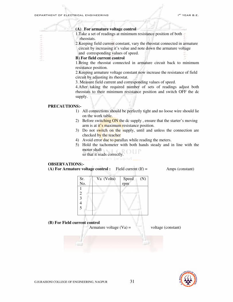
(A) For armature voltage control
1.Take a set of readings at minimum resistance position of both rheostats. 2.Keeping field current constant, vary the rheostat connected in armature circuit by increasing it’s value and note down the armature voltage and corresponding values of speed. B) For field current control 1.Bring the rheostat connected in armature circuit back to minimum resistance position. 2.Keeping armature voltage constant now increase the resistance of field circuit by adjusting its rheostat. 3. Measure field current and corresponding values of speed. 4.After taking the required number of sets of readings adjust both rheostats to their minimum resistance position and switch OFF the dc supply.
PRECAUTIONS:-
1) All connections should be perfectly tight and no loose wire should lie on the work table.
2) Before switching ON the dc supply , ensure that the starter’s moving arm is at it’s maximum resistance position.
3) Do not switch on the supply, until and unless the connection are checked by the teacher
4) Avoid error due to parallax while reading the meters. 5) Hold the tachometer with both hands steady and in line with the
motor shaft so that it reads correctly.
OBSERVATIONS:- (A) For Armature voltage control : Field current (If) = Amps (constant)
Sr. No.
Va (Volts) Speed (N) rpm
1 2 3 4 5
(B) For Field current control
Armature voltage (Va) = voltage (constant)

DEPARTMENT OF ELECTRICAL ENGINEERING Ist YEAR B.E.
G.H.RAISONI COLLEGE OF ENGINEERING, NAGPUR 32
GRAPH: - Plot the following on separate graph papers. 1) N verses Va 2) N verses If
CONCLUSION:- It is observed that the speed of dc shunt motor increases above normal value by field current control method and decreases below normal value by armature control method.
DISCUSSION:- Q.1.What are the limitations of armature voltage control and field current
control methods? Q.2. Why both rheostats are kept at minimum resistance position in the
starting condition? Q.3. What is starter? Why is it required? Q.4. What is back emf? What is it’s significances? Q.5. Why is starter required during starting condition & not during
running condition? Q.6. Draw internal and external characteristics of dc shunt motor. Q.7. What are the applications of dc shunt motor? Q.8. Why are brushes made form carbon? Q.9. Why is thin conductor used for field winding? & thick conductor for
armature winding?
Note: Answer any 04 as total by your teacher
REFERENCES:- 1. A text book on laboratory experiments in electrical engg.
Kharbanda & Tarnekar 2. Electrical technology Vol-I I – B.L. Theraja ---------------------------------------------------------------------------------------------------------------------
Sr. No.
If (amp) Speed(N) rpm.
1 2 3 4 5