
Attachment 1_Proposed list of prioritised NCIPAP … - NCIPAP... · Web viewATTACHMENT 1: Proposed...
29
ATTACHMENT 1: Proposed List of Prioritised NCIPAP Projects Priority Project 1 – Altona Terminal Station (ATS) Transmission Circuit / Injection Point Altona Terminal Station (ATS) Limit and Reason for the Limit The summer cyclic rating of the secondary winding of the B4 220/66kV transformer at ATS is 1520A. The transformer capacity is limited by the secondary protection relay with a rating of 1000 A. Project Protection setting change of the SEL 387-5 protection relay at ATS Limit Addressed Loading constraint of the B4 220/66kV transformer at ATS Project Description The High Voltage Overcurrent Setting on the SEL 387-5 relay is limiting the transformer capacity. Change the protection setting to achieve required limit and test relay on site. Present Limit ATS 220/66 kV B4 transformer rating 174 MVA but limited by protection limit of 114 MVA Target Limit ATS 220/66 kV B4 transformer capability 174 MVA. Capital Cost $0 Operating Cost $14k Priority project improvement target Increase limiting factor of the secondary winding of the B4 220/66kV transformer at ATS to 1520A. Reasons to undertake the project: The TCPR shows the ATS 220/66 kV transformation N-1 capacity as 174 MVA. The DNSPs were not aware of the limitation caused by the protection limit, which limits the transformation capacity to 114 MVA. The maximum demand at ATS was 189.4 MVA in summer 2012/13 and is forecasted to increase. Having identified this limitation, the DNSPs have requested to remove the protection limit as soon as possible. This increase in rating would avoid or minimise potential load shedding from 2013/14 onwards due to the forecast load growth at ATS. This project would increase the reliability of supply to customers connected to ATS. Benefit: Removal of the protection limit will allow full utilisation of the transformer capability. This project increases the ATS 220/66 kV B4 transformer capability by 60 MVA.
Transcript of Attachment 1_Proposed list of prioritised NCIPAP … - NCIPAP... · Web viewATTACHMENT 1: Proposed...

ATTACHMENT 1: Proposed List of Prioritised NCIPAP Projects
Priority Project 1 – Altona Terminal Station (ATS)Transmission Circuit / Injection Point Altona Terminal Station (ATS)
Limit and Reason for the Limit
The summer cyclic rating of the secondary winding of the B4 220/66kV transformer at ATS is 1520A. The transformer capacity is limited by the secondary protection relay with a rating of 1000 A.
Project Protection setting change of the SEL 387-5 protection relay at ATSLimit Addressed Loading constraint of the B4 220/66kV transformer at ATS
Project DescriptionThe High Voltage Overcurrent Setting on the SEL 387-5 relay is limiting the transformer capacity. Change the protection setting to achieve required limit and test relay on site.
Present Limit ATS 220/66 kV B4 transformer rating 174 MVA but limited by protection limit of 114 MVA
Target Limit ATS 220/66 kV B4 transformer capability 174 MVA.Capital Cost $0Operating Cost $14kPriority project improvement target
Increase limiting factor of the secondary winding of the B4 220/66kV transformer at ATS to 1520A.
Reasons to undertake the project: The TCPR shows the ATS 220/66 kV transformation N-1 capacity as 174 MVA. The DNSPs were not aware of the limitation caused by the protection limit, which limits the transformation capacity to 114 MVA. The maximum demand at ATS was 189.4 MVA in summer 2012/13 and is forecasted to increase. Having identified this limitation, the DNSPs have requested to remove the protection limit as soon as possible.This increase in rating would avoid or minimise potential load shedding from 2013/14 onwards due to the forecast load growth at ATS. This project would increase the reliability of supply to customers connected to ATS.Benefit:Removal of the protection limit will allow full utilisation of the transformer capability. This project increases the ATS 220/66 kV B4 transformer capability by 60 MVA.

Priority Project 2 - Rowville - Malvern No.1 & 2 220 kV circuitsTransmission Circuit / Injection Point Rowville – Malvern No.1 & 2 220 kV circuits
Limit and Reason for the Limit
AEMO identified loading constraints for the Rowville – Malvern 220kV lines in the Victorian Annual Planning Report 2013. Under peak demand conditions in summer and following an outage of one of the Rowville – Malvern 220kV circuits, the remaining Rowville – Malvern 220kV circuit is forecast to be loaded above its short term (15-minute) rating (237MVA at 45 °C and 0.6 m/s wind speed) from summer 2013-14.
Project Install a wind monitoring scheme for the Rowville–Malvern No.1 & 2 220 kV circuits
Limit Addressed Loading constraints of the Rowville – Malvern No.1 & 2 220 kV circuits under single contingency events
Project DescriptionInstallation of a wind monitoring station at Malvern Terminal Station (there is an existing wind monitoring station at Rowville Terminal Station). Changes to the control and protection schemes to incorporate wind monitoring stations outputs.
Present Limit Ratings of Rowville-Malvern 220 kV circuits: 204 MVA continuous and 237 MVA short-term
Target
Implement dynamic rating for both ROTS-MTS 220 kV circuits. The scheme will be designed to achieve ratings of ROTS-MTS circuits under favourable ambient conditions as 234 MVA for system normal operation and 267 MVA under contingent conditions provided pre-contingency loading is less than 60% of 234 MVA.
Estimated Capital Cost $400k
Operating Cost $0Priority project improvement target
Dynamic line rating scheme for the Rowville – Malvern No.1 & 2 220 kV circuits
Reasons to undertake the project: An increase in the rating of the Rowville-Malvern 220 kV circuits is expected under favourable ambient and wind speed conditions with the application of dynamic line rating. This increase in rating would avoid or minimise potential load shedding from 2013/14 onwards due to the forecast load growth at Malvern Terminal Station. This project would increase the security of supply to customers connected to Malvern Terminal Station.Benefits: AEMO’s 2013 Victorian Annual Planning Report assessment identified net market benefit for implementation of a wind monitoring scheme on the Rowville-Malvern 220 kV circuits for 2014/15 and 2015/16 are $38,000 and $132,000 respectively. The gross market benefits for 2014/15 and 2015/16 are $86,000 and $181,000 respectively.

Priority Project 3 – Dederang circuits
Transmission Circuit / Injection Point
(1) Dederang-Glenrowan No.3 220kV circuit(2) Dederang-Murray No.1 & No.2 330kV circuit(3) Dederang- Wodonga No.1 330kV circuit[Limiting element at Dederang Terminal Station (DDTS)]
Limit and Reason for the Limit
The Dederang-Glenrowan No.3 220kV circuit is rated at 450 MVA (continuous rating at 35 °C) and is double switched at DDTS. The line is limited by the interplant connections (431 MVA) and secondary plants at DDTS when single switched due to plant outages.The Dederang-Murray No.1 and No.2 330kV circuits are rated at 1043 MVA (continuous rating at 35 °C) and is switched in a circuit breaker and a half switch bay at DDTS. The line is limited by the interplant connections (943 MVA) for a circuit breaker outage at DDTS.The Dederang-Wodonga No.1 330kV circuit are rated at 977 MVA (continuous rating at 35 °C) and is switched in a circuit breaker and a half switch bay at DDTS. The line is limited by the interplant connections (943 MVA) for a circuit breaker outage at DDTS. The line capacity is also limited by secondary protection relays with a lower rating of 915 MVA at DDTS.
Project Replacement of the 330kV and 220 kV interplant connections and protection setting change at DDTS
Limit Addressed Loading constraint of the above 220kV and 330kV lines under single contingency event
Project DescriptionReplace the 330kV and 220 kV interplant connections at DDTS to enable full use of the capacity of the 330kV and 220kV lines connected at DDTS. Change the protection settings to achieve required limits and test relays on site.
Present Limit
DDTS-GNTS No.3 220 kV circuit capability limited by interplant connections with rating of 431 MVA;DDTS-MSS No.1 and No.2 330 kV circuits capability limited by interplant connections with rating of 943 MVA; andDDTS-WOTS 30 kV circuit capability is limited by protection limit of 915 MVA.
TargetDDTS-GNTS No.3 220 kV circuit capability 450 MVA;DDTS-MSS No.12 and No.2 330 kV circuits capability 1043 MVA; andDDTS-WOTS 330 kV circuit capability 977 MVA.
Capital Cost $586kOperating Cost $0
Priority project improvement target
Full use of line thermal capacity of 450MVA, 1043MVA and 977MVA of the (1) Dederang-Glenrowan No.3 220kV circuit, (2) Dederang-Murray No.1 and No.2 330kV circuit and (3) Dederang- Wodonga No.1 330kV circuit respectively during both normal and contingency conditions.
Reasons to undertake the project:The Murray - Dederang 330 kV circuits thermal capacity is one of top 20 binding Vic transmission constraints. In 2011 and 2012 the Marginal Cost of Constraints (MCC) have been $87,009 and $212,498. The upgrade of the 330kV and 220kV interplant connections and the protection setting changes will enable full use of the capacity of the 330kV and 220kV linesBenefits: This project would increase the market benefit and reduce the generation dispatch costs.

Priority Project 4 - South Morang – Thomastown No.1 & 2 220 kV circuitsTransmission Circuit / Injection Point South Morang -Thomastown No.1 & 2 220 kV circuits
Limit and Reason for the Limit
AEMO identified an operational loading constraint on the South Morang–Thomastown 220 kV circuits with prior outage conditions of a 500/220 kV transformer or any other major element in the Greater Melbourne area. The South Morang to Thomastown 220 kV circuits are rated at 549 MVA continuous and 604 MVA short term (at 45 °C and 0.6 m/s wind speed).
Project Install a wind monitoring scheme for the South Morang – Thomastown No.1 & 2 220 kV circuits
Limit Addressed Operational loading constraint for the South Morang – Thomastown No.1 & 2 220 kV circuits
Project DescriptionInstallation of wind monitoring stations at South Morang and Thomastown Terminal Stations. Required changes to the control and protection schemes to incorporate wind monitoring station outputs.
Present Limit South Morang-Thomastown No.1 and No.2 220 kV circuit rating: 549 MVA continuous
Target LimitImplement dynamic rating for both SMTS-TTS 220 kV circuits. The scheme will be designed to achieve ratings of SMTS-TTS circuits as 628MVA for system normal operation under favourable ambient conditions. No increase in the emergency rating is expected.
Estimated Capital Cost $600k
Operating Cost $0Priority project improvement target
Dynamic line rating scheme for the South Morang to Thomastown No.1 and 2 220 kV circuits
Reasons to undertake the project:Thermal capacity of the South Morang-Thomastown 220 kV circuits is one of top 25 binding Vic transmission constraints. This increase in rating would minimise the market congestion caused by thermal limitation of these circuits. Particularly this limitation is likely to occur during prior outage of a 500/220 kV transformer or other major plant in the Greater Melbourne area.Benefits: AEMO considers improvement on thermal rating likely to reduce the market spot prices caused by constraints on the South Morang-Thomastown 220 kV circuits.

Priority Project 5 – Wodonga Terminal Station (WOTS)Transmission Circuit / Injection Point Wodonga Terminal Station (WOTS)
Limit and Reason for the Limit
The summer cyclic rating of the tertiary winding of the No.1 and No.2 330/66/22 kV transformers at WOTS are both 1154A. The 22kV cables connecting the transformers to the 22kV switchroom has a lower rating of 830A and are limiting the capacity of the transformers.
Project Replace the 22kV cable connections between the 22 kV switchroom and the No.1 and No.2 transformers at WOTS
Limit Addressed Loading constraint of the No.1 and No.2 330/66/22 kV transformers at WOTS
Project DescriptionReplace the 22kV cable connections between the 22 kV switchroom and the No.1 and No.2 transformers at WOTS to match or exceed the cyclic rating of the transformers
Present Limit The 22 kV side of WOTS 330/66/22 kV No.1 and No.2 transformers rating is 44 MVA and limited by the 22 kV cable rating of 32 MVA
Target Limit The 22 kV side of WOTS 330/66/22 kV No.1 and No.2 transformers capability is 44 MVA.
Capital Cost $778kOperating Cost $0Priority project improvement target
Increase the limiting factor of the tertiary winding of the WOTS No.1 and 2 330/66/22 kV transformers to 1154A.
Reasons to undertake the project: The 22kV cable upgrades enable full use of the installed transformer capacity.This increase in rating would avoid or minimise potential load shedding from 2013/14 onwards due to the forecast load growth at Wodonga Terminal Station. This project would increase the reliability of supply to customers connected to Wodonga Terminal Station.Benefit:WOTS 330/66/22 kV transformer 22 kV side capability increases by 12 MVA.

Priority Project 6 – Rowville - East Rowville No.1 & No.2 220kV circuit & Rowville - Springvale No.2 220kV circuit
Transmission Circuit / Injection Point
Rowville - East Rowville No.1 & No.2 220kV circuit & Rowville - Springvale No.2 220kV circuit[Limiting element at Rowville Terminal Station (ROTS)]
Limit and Reason for the Limit
These circuits are rated at 800 MVA (continuous) at 35 °C and are connected in circuit breaker and a half switch bays at ROTS. The secondary protection relays for the ERTS No.1 and No.2 lines at ROTS have lower rating settings of 686 MVA. The two 220kV isolators in the SVTS No.2 line bay at ROTS have lower ratings of 495MVA compared with the line.During a prior outage of the circuit breaker between Rowville No.4 220 kV bus and Rowville-Springvale No.2 220 kV circuit, this circuit can be switched on to Rowville No.1 220 kV bus. In this switching configuration two 220 kV isolators between Rowville No.1 220 kV bus and Rowville-Springvale No.2 220 kV circuit would limit the flow on the Rowville-Springvale 220 kV circuits to 495 MVA compared with the line rating of 800 MVA.
ProjectReplace the two 220kV isolators in the SVTS No.2 line bay at ROTS and make protection setting changes for the Rowville - East Rowville No.1 and No.2 220kV circuits at ROTS.
Limit AddressedLoading constraint of the Rowville - East Rowville No.1 and No.2 220kV circuits and Rowville - Springvale No.2 220kV circuit under single contingency events
Project DescriptionReplace two 220kV isolators in the SVTS No.2 line bay at ROTS, change the relay settings for the Rowville - East Rowville No.1 and No.2 220kV circuits at ROTS to achieve the required limit and test relays on site.
Present LimitROTS-ERTS No.1 and 2 220 kV circuits capability limited by protection limit of 686 MVA.Rating of isolators between ROTS No.1 220 kV bus and ROTS-SVTS No.2 line limited to 495 MVA.
Target LimitROTS-ERTS No.1 and 2 220 kV circuits capability limited by circuit rating of 800 MVA.Rating of isolators between ROTS No.1 220 kV bus and ROTS-SVTS No.2 line increased to 800 MVA or higher.
Capital Cost $999kOperating Cost $0Priority project improvement target Full use of line capacity for each line (800MVA).
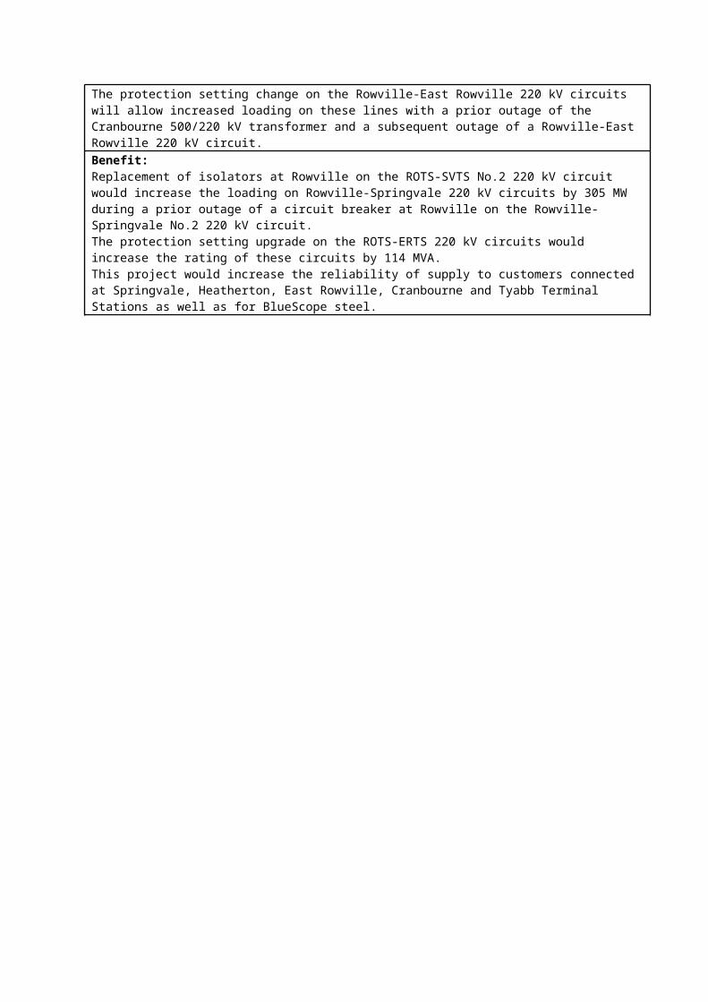
Reasons to undertake the project: The replacement of the 220kV isolators at Springvale will remove the constraints on the Rowville-Springvale 220 kV circuits during a prior outage of a circuit breaker at Rowville Terminal Station.The protection setting change on the Rowville-East Rowville 220 kV circuits will allow increased loading on these lines with a prior outage of the Cranbourne 500/220 kV transformer and a subsequent outage of a Rowville-East Rowville 220 kV circuit.Benefit:Replacement of isolators at Rowville on the ROTS-SVTS No.2 220 kV circuit would increase the loading on Rowville-Springvale 220 kV circuits by 305 MW during a prior outage of a circuit breaker at Rowville on the Rowville-Springvale No.2 220 kV circuit.The protection setting upgrade on the ROTS-ERTS 220 kV circuits would increase the rating of these circuits by 114 MVA.This project would increase the reliability of supply to customers connected at Springvale, Heatherton, East Rowville, Cranbourne and Tyabb Terminal Stations as well as for BlueScope steel.

Priority Project 7– Hazelwood – Loy Yang No.1, 2 & 3 220 kV circuitsTransmission Circuit / Injection Point Hazelwood – Loy Yang No.1, 2 & 3 500 kV circuits
Limit and Reason for the Limit
AEMO identified an operational loading constraint on the Hazelwood – Loy Yang 500 kV circuits with a prior outage of one of the other parallel transmission lines between Hazelwood and Loy Yang. Each of the Hazelwood – Loy Yang 500 kV circuits are rated at 3204 MVA and 4191 MVA at 35 °C and 5 °C.With a prior outage of one of the parallel circuits and for secure operation the loading on the remaining two lines are limited to the thermal capacity of a single circuit. This is to ensure that for the next contingent outage of a Loy Yang–Hazelwood 500 kV circuit, the last remaining parallel circuit loading remains within its thermal capacity. The total generation connected at Loy Yang 500 kV, including 600 MW import from Tasmania, is about 3800 MW. There is no generation constraint during low ambient temperature periods with a prior outage of a Loy Yang-Hazelwood 500 kV circuit. A prior outage of a Loy Yang–Hazelwood 500 kV circuit at an ambient temperature of 35 °C can limit generation to about 600 MW from Loy Yang 500 kV including import from Tasmania.
Project Dynamic line model development and implementation to enable the calculation of continuous and short-term line ratings dynamically based on ambient temperature.
Limit Addressed Operational loading constraint for the Hazelwood – Loy Yang No.1, 2 & 3 500 kV circuits
Project DescriptionDevelop and implement a thermal model to calculate continuous and short-term ratings for the Hazelwood-Loy Yang 500 kV circuits based on ambient temperatures.
Present Limit Hazelwood-Loy Yang No.1, 2 & 3 500 kV circuit capability 3204 MVA (summer continuous)
Target LimitHazelwood-Loy Yang No.1, 2 & 3 500 kV circuits capability implemented in the thermal line model based on ambient temperatures. This is likely to provide short-term ratings higher than the continuous ratings under favourable ambient temperature and operating conditions.
Estimated Capital Cost $0
Operating Cost $2k
Priority project improvement target
Dynamic line thermal model development and implementation for the Hazelwood-Loy Yang No.1, 2 & 3 500 kV circuits based on ambient temperatures.
Reasons to undertake the project:Market constraints were recorded during prior outage of a Hazelwood-Loy Yang 500 kV circuit. The proposed project would enable applying short-term ratings to the Hazelwood-Loy Yang 500 kV circuits under favourable ambient temperatures and operating conditions. Availability of short term rating information avoids or minimises the market constraints caused by the Hazelwood-Loy Yang 500 kV circuits.Benefits:The proposed project will enable application of short term ratings for the Hazelwood-Loy Yang 500 kV circuits based on ambient temperatures. This project will reduce generation dispatch costs.

Priority Project 8 – Templestowe Terminal Station (TSTS)Transmission Circuit / Injection Point Templestowe Terminal Station (TSTS)
Limit and Reason for the Limit
The summer cyclic rating of the secondary winding of the TSTS B1, B2 and B3 220/66 kV transformer are 1636A, 1528A and 1684A. The B1 and B3 transformer are limited by the 66kV busbars (1585A) and the 66kV interplant connections (1510A). The cost of busbar replacement is significant and outside the scope of the NCIPAP. The B2 transformer is limited by 66kV interplant connections that have incorrect equipment ratings recorded in RADAR (SP AusNet database).
ProjectReplace the 66kV interplant connections between the 66kV busbars and the B1 and B3 transformers at TSTS and review and uprate equipment ratings in RADAR
Limit Addressed Loading constraint of the B1, B2 and B3 220/66 kV transformers at TSTS
Project DescriptionReplace the limiting 66kV interplant connections between the 66kV busbar and the B1 and B3 transformers at TSTS to match or exceed the B1 and B3 transformer ratings. Review and uprate equipment ratings in RADAR.
Present Limit
TSTS 220/66 kV B1 transformer rating 187 MVA and limited by interplant connection rating of 173 MVA;TSTS 220/66 kV B3 transformer rating 192 MVA and limited by interplant connection rating of 173 MVA; andTSTS 220/66 kV B2 transformer rating 175 MVA and limited by interplant connection rating of 173 MVA;
Target Limit
TSTS 220/66 kV B1 transformer rating 187 MVA and limited by 66 kV busbar rating of 181 MVA;TSTS 220/66 kV B3 transformer rating 192 MVA and limited by 66 kV busbar rating of 181 MVA; andTSTS 220/66 kV B2 transformer capability 175 MVA.
Capital Cost $377kOperating Cost $0
Priority project improvement target
Increase the limiting factor of the B1 and B3 220/66 kV transformers branches to the busbar rating of 1585A.Increase the limiting factor of the B2 220/66 kV transformer branch to 1528A.
Reasons to undertake the project: This project increases the B1, B2 and B3 220/66 kV transformation capacity at TSTS.This increase in rating would minimise potential load shedding from 2013/14 onwards due to the forecast load growth at Templestowe terminal station. This project would increase the reliability of supply to customers connected to Templestowe terminal station.Benefit:TSTS 220/66 kV transformer capability increases by 8 MVA.
Priority Project 9 – South Morang - Dederang No.1 & No.2 330kV circuitsTransmission Circuit / Injection Point
South Morang - Dederang No.1 & No.2 330kV circuits[System Overload Control Schemes (SOCs) layout modification]
Limit and Reason for the Limit
AEMO uses real time rating information from SOCs to operate the transmission system. The presentation of the South Morang (SMTS) series capacitor banks and South Morang to Dederang (DDTS) 330 kV line ratings in SOCS needs some modification to avoid operators interpreting the rating information incorrectly and constraining flows on the 330 kV interconnector between NSW and Victoria.
Project Develop the SOCS layout to display the combined SMTS-DDTS 330kV line and series capacitor bank ratings
Limit AddressedCorrectly displaying the SMTS-DDTS 330kV line ratings in SOCS will minimise the risk of operators interpreting the rating information incorrectly and constraining flows on the 330 kV interconnector between Victoria and New South Wales.
Project Description
Modify the SOCs interface to display a calculated value for the Continuous, 5 minute and 15 minute ratings being the lower of the line and the capacitor bank ratings for each of Continuous, 5 minute and 15 minute ratings and include a SCADA solution to monitor whether the 330kV series capacitors are in service or bypassed.
Capital Cost $72kOperating Cost $0
Priority project improvement target
Improved presentation of rating information for the SMTS-DDTS 330kV lines and series capacitor banks in SOCS to assist operators and minimise the risk of operators interpreting the rating information incorrectly.
Reasons to undertake the project:SMTS-DDTS 330 kV line thermal capacity is one of top 20 binding Victorian transmission constraints. In 2011 and 2012 the marginal cost of constraints have been $12,584 and $38,874. Any incorrect interpretation of the rating of the SMTS-DDTS 330 kV circuits can result in market congestion and increased generation dispatch costs. This project is to modify the SOCS layout to improve the presentation of the line and capacitor bank ratings to operational staff.Benefit:Improved the operational visibility of the line and series capacitor thermal constraints on the South Morang-Dederang 330 kV circuits. This project will improve the market benefit to the customers.

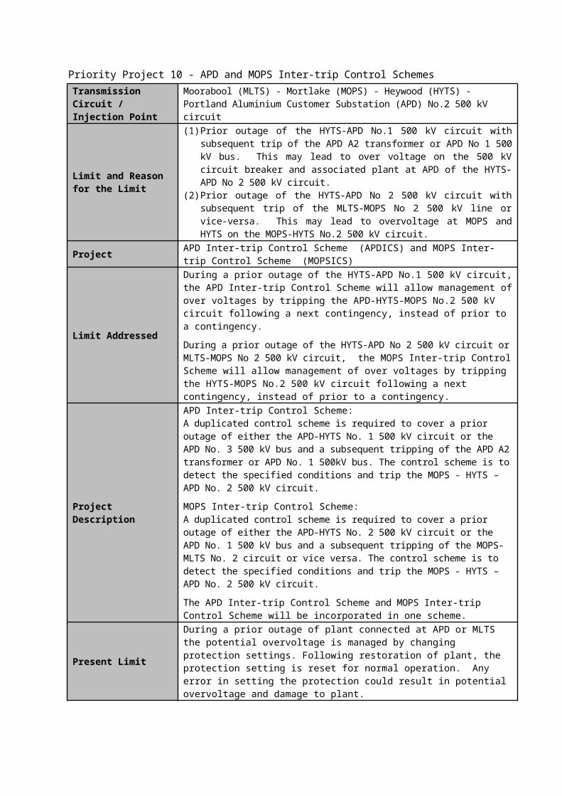
Priority Project 10 - APD and MOPS Inter-trip Control SchemesTransmission Circuit / Injection Point
Moorabool (MLTS) - Mortlake (MOPS) - Heywood (HYTS) - Portland Aluminium Customer Substation (APD) No.2 500 kV circuit
Limit and Reason for the Limit
(1) Prior outage of the HYTS-APD No.1 500 kV circuit with subsequent trip of the APD A2 transformer or APD No 1 500 kV bus. This may lead to over voltage on the 500 kV circuit breaker and associated plant at APD of the HYTS-APD No 2 500 kV circuit.
(2) Prior outage of the HYTS-APD No 2 500 kV circuit with subsequent trip of the MLTS-MOPS No 2 500 kV line or vice-versa. This may lead to overvoltage at MOPS and HYTS on the MOPS-HYTS No.2 500 kV circuit.
Project APD Inter-trip Control Scheme (APDICS) and MOPS Inter-trip Control Scheme (MOPSICS)
Limit Addressed
During a prior outage of the HYTS-APD No.1 500 kV circuit, the APD Inter-trip Control Scheme will allow management of over voltages by tripping the APD-HYTS-MOPS No.2 500 kV circuit following a next contingency, instead of prior to a contingency.
During a prior outage of the HYTS-APD No 2 500 kV circuit or MLTS-MOPS No 2 500 kV circuit, the MOPS Inter-trip Control Scheme will allow management of over voltages by tripping the HYTS-MOPS No.2 500 kV circuit following a next contingency, instead of prior to a contingency.
Project Description
APD Inter-trip Control Scheme:A duplicated control scheme is required to cover a prior outage of either the APD-HYTS No. 1 500 kV circuit or the APD No. 3 500 kV bus and a subsequent tripping of the APD A2 transformer or APD No. 1 500kV bus. The control scheme is to detect the specified conditions and trip the MOPS - HYTS – APD No. 2 500 kV circuit.
MOPS Inter-trip Control Scheme:A duplicated control scheme is required to cover a prior outage of either the APD-HYTS No. 2 500 kV circuit or the APD No. 1 500 kV bus and a subsequent tripping of the MOPS-MLTS No. 2 circuit or vice versa. The control scheme is to detect the specified conditions and trip the MOPS - HYTS – APD No. 2 500 kV circuit.
The APD Inter-trip Control Scheme and MOPS Inter-trip Control Scheme will be incorporated in one scheme.
Present Limit
During a prior outage of plant connected at APD or MLTS the potential overvoltage is managed by changing protection settings. Following restoration of plant, the protection setting is reset for normal operation. Any error in setting the protection could result in potential overvoltage and damage to plant.
Target Limit Prevent potential overvoltage at APD 500 kV bus during a prior outage of plant connected at APD and MLTS. Minimise potential human error.
Estimated Capital Cost
$400kThe APD inter-trip control scheme and MOPS inter-trip control scheme could only be carried out for this price provided the M2 contingency control scheme is completed.
Operating Cost $0Priority project improvement target
Fully functional APD Inter-trip Control Scheme (APDICS) and MOPS Inter-trip Control Scheme (MOPSICS) are provided for this line
Reasons to undertake the project:APD Inter-trip Control Scheme: To prevent potential overvoltage conditions on circuit breakers and associated plant at APD connected to HYTS-APD No.2 circuit.
MOPS Inter-trip Control Scheme: To prevent potential excessive voltage levels at HYTS 500 kV and on the HYTS – MOPS No.2 500 kV circuit.Benefits:Proposed control schemes will provide increased maintenance window for elements in MLTS-MOPS-HYTS-APD 500 kV circuits. Human error minimised. Potential damage to plant is minimised.

Priority Project 11 - M2 Contingency Control SchemeTransmission Circuit / Injection Point M2 500/275/22kV transformer at Heywood Terminal Station (HYTS)
Limit and Reason for the Limit
The M2 Contingency Control Scheme will prevent voltage collapse and Heywood 500/275 kV M2 transformer overload with prior outage of the APD-HYTS No.1 500 kV circuit plus contingent outage of the MLTS-MOPS No.2 500 kV circuit.
Project M2 Contingency Control Scheme
Limit AddressedThe control scheme will prevent voltage collapse and overloading of Heywood 500/275 kV M2 transformer following a prior outage of APD-HYTS No.1 500 kV circuit plus contingent outage the MLTS-MOPS No.2 500 kV circuit.
Project Description
A duplicated control scheme is required to cover prior outages between HYTS and APD associated with the No. 1 Line and a subsequent outage of the MLTS-MOPS No. 2 Line, or the reverse. Either scenario may lead to voltage collapse and plant overload. The control scheme is to detect the specified conditions and trip the APD potlines.
Present LimitDuring a prior outage of the HYTS-APD No.1 500 kV circuit, VIC to SA export would be reduced to manage potential over loading on the HYTS M1 transformer.
Target LimitDuring a prior outage of the HYTS-APD No.1 500 kV circuit, reduction in VIC to SA export would be minimised to manage potential over loading on HYTS M1 transformer.
Estimated Capital Cost $800k
Operating Cost $0Priority project improvement target
Fully functional M2 contingency control scheme is provided for the M2 transformer at HYTS
Reasons to undertake the project:To prevent voltage collapse and plant overload during certain contingency scenarios.Benefits:Proposed control schemes will provide increased maintenance window for elements in MLTS-MOPS-HYTS-APD 500 kV circuits. Avoidance of pre-contingent action will reduce the generation dispatch costs.

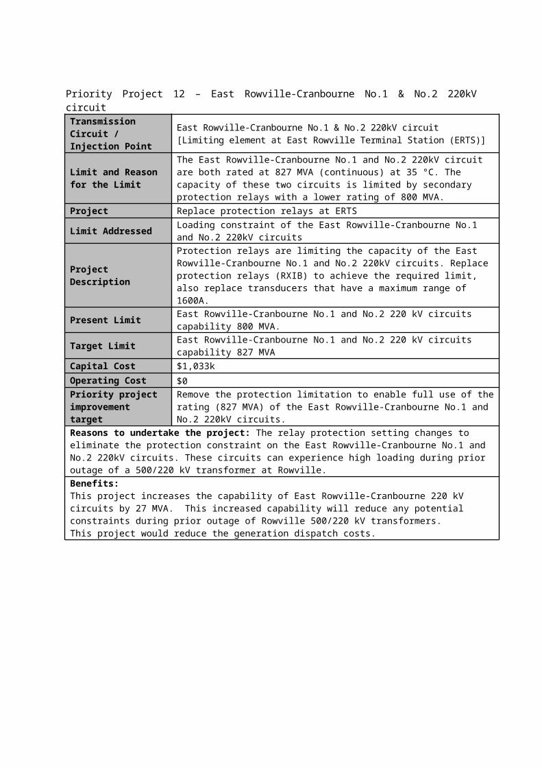
Priority Project 12 – East Rowville-Cranbourne No.1 & No.2 220kV circuitTransmission Circuit / Injection Point
East Rowville-Cranbourne No.1 & No.2 220kV circuit[Limiting element at East Rowville Terminal Station (ERTS)]
Limit and Reason for the Limit
The East Rowville-Cranbourne No.1 and No.2 220kV circuit are both rated at 827 MVA (continuous) at 35 °C. The capacity of these two circuits is limited by secondary protection relays with a lower rating of 800 MVA.
Project Replace protection relays at ERTS
Limit Addressed Loading constraint of the East Rowville-Cranbourne No.1 and No.2 220kV circuits
Project DescriptionProtection relays are limiting the capacity of the East Rowville-Cranbourne No.1 and No.2 220kV circuits. Replace protection relays (RXIB) to achieve the required limit, also replace transducers that have a maximum range of 1600A.
Present Limit East Rowville-Cranbourne No.1 and No.2 220 kV circuits capability 800 MVA.Target Limit East Rowville-Cranbourne No.1 and No.2 220 kV circuits capability 827 MVACapital Cost $1,033kOperating Cost $0Priority project improvement target
Remove the protection limitation to enable full use of the rating (827 MVA) of the East Rowville-Cranbourne No.1 and No.2 220kV circuits.
Reasons to undertake the project: The relay protection setting changes to eliminate the protection constraint on the East Rowville-Cranbourne No.1 and No.2 220kV circuits. These circuits can experience high loading during prior outage of a 500/220 kV transformer at Rowville.Benefits:This project increases the capability of East Rowville-Cranbourne 220 kV circuits by 27 MVA. This increased capability will reduce any potential constraints during prior outage of Rowville 500/220 kV transformers.This project would reduce the generation dispatch costs.

Priority Project 13 – Keilor-Sydenham No.1 500kV circuit & Keilor-South Morang No.1 500kV circuitTransmission Circuit / Injection Point
Keilor-Sydenham No.1 500kV circuit & Keilor-South Morang No.1 500kV circuit[Limiting element at Keilor Terminal Station (KTS)]
Limit and Reason for the Limit
The Keilor-Sydenham No.1 500kV circuit and Keilor-South Morang No.1 500 kV circuit are both rated at 3204 MVA (continuous) at 35ºC and connected in a circuit breaker and a half switch bay at KTS. The line capacity is limited by secondary equipment at KTS with ratings in the range of 873 MVA to 1949 MVA. A project (XC06) was completed to increase the rating of the secondary equipment, however the new ratings have not been updated in RADAR (SP AusNet database).
Project Review and uprate equipment ratings in RADAR
Limit AddressedLoading constraint of the Keilor-Sydenham No.1 500kV circuit and Keilor-South Morang No.1 500kV circuit during prior outage of 500 kV circuit breakers at KTS
Project Description Review and uprate equipment ratings in RADAR
Present LimitKeilor-Sydenham No.1 500 kV circuit: Protection limit 873 MVA to1949 MVAKeilor-South Morang No.1 500 kV circuit: Protection limit 873 MVA to1506 MVA
Target Limit Keilor-Sydenham No.1 500 kV circuit: Secondary plant limit 2078 MVA; andKeilor-South Morang No.1 500 kV circuit: Secondary plant limit 2078 MVA
Capital Cost $0Operating Cost $0
Priority project improvement target
Remove the protection constraints for the Keilor-Sydenham No.1 500 kV circuit and Keilor-South Morang No.1 500 kV circuit. This will result in increased ratings of 2078 MVA.
Reasons to undertake the project: The secondary equipment is limiting line capacity due to incorrect equipment ratings recorded in RADAR (SP AusNet database). The database will be reviewed and updated by SP AusNet.Benefit:This project increases supply reliability to Greater Melbourne area and reduce generation dispatch costs.
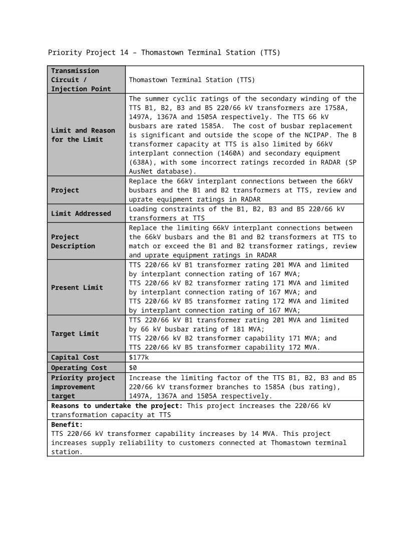
Priority Project 14 – Thomastown Terminal Station (TTS)
Transmission Circuit / Injection Point Thomastown Terminal Station (TTS)
Limit and Reason for the Limit
The summer cyclic ratings of the secondary winding of the TTS B1, B2, B3 and B5 220/66 kV transformers are 1758A, 1497A, 1367A and 1505A respectively. The TTS 66 kV busbars are rated 1585A. The cost of busbar replacement is significant and outside the scope of the NCIPAP. The B transformer capacity at TTS is also limited by 66kV interplant connection (1460A) and secondary equipment (638A), with some incorrect ratings recorded in RADAR (SP AusNet database).
ProjectReplace the 66kV interplant connections between the 66kV busbars and the B1 and B2 transformers at TTS, review and uprate equipment ratings in RADAR
Limit Addressed Loading constraints of the B1, B2, B3 and B5 220/66 kV transformers at TTS
Project DescriptionReplace the limiting 66kV interplant connections between the 66kV busbars and the B1 and B2 transformers at TTS to match or exceed the B1 and B2 transformer ratings, review and uprate equipment ratings in RADAR
Present Limit
TTS 220/66 kV B1 transformer rating 201 MVA and limited by interplant connection rating of 167 MVA;TTS 220/66 kV B2 transformer rating 171 MVA and limited by interplant connection rating of 167 MVA; andTTS 220/66 kV B5 transformer rating 172 MVA and limited by interplant connection rating of 167 MVA;
Target LimitTTS 220/66 kV B1 transformer rating 201 MVA and limited by 66 kV busbar rating of 181 MVA;TTS 220/66 kV B2 transformer capability 171 MVA; andTTS 220/66 kV B5 transformer capability 172 MVA.
Capital Cost $177kOperating Cost $0
Priority project improvement target
Increase the limiting factor of the TTS B1, B2, B3 and B5 220/66 kV transformer branches to 1585A (bus rating), 1497A, 1367A and 1505A respectively.
Reasons to undertake the project: This project increases the 220/66 kV transformation capacity at TTSBenefit:TTS 220/66 kV transformer capability increases by 14 MVA. This project increases supply reliability to customers connected at Thomastown terminal station.

Priority Project 15 – Ringwood Terminal Station (RWTS)
Transmission Circuit / Injection Point Ringwood Terminal Station (RWTS)
Limit and Reason for the Limit
The summer cyclic rating of the secondary windings of the RWTS B2 and B3 220/66 kV transformers are rated at 1623A and 1660A respectively. The B2 and B3 transformer capacity is limited by 66kV interplant connections with a lower rating of 1510 A. This is due to incorrect equipment ratings recorded in RADAR (SP AusNet database). The capacity of the transformers is also limited by the 66kV busbars with a rating of 1585A. The cost of busbar replacement is significant and outside the scope of the NCIPAP.
Project Review and uprate equipment ratings in RADARLimit Addressed Loading constraint of the RWTS 220/66 kV transformers (B2 and B3)
Project Description Review and uprate the 66kV interplant connection ratings in RADAR.
Present LimitRWTS 220/66 kV B2 transformer rating 185 MVA and limited by interplant connection rating of 173 MVA; andRWTS 220/66 kV B3 transformer rating 190 MVA and limited by interplant connection rating of 173 MVA
Target LimitRWTS 220/66 kV B2 transformer rating 185 MVA and limited by 66 kV busbar rating of 181 MVA; andRWTS 220/66 kV B3 transformer rating 190 MVA and limited by 66 kV busbar rating of 181 MVA.
Capital Cost $0Operating Cost $0Priority project improvement target
Increase the limiting factor of the RWTS B2 and B3 220/66 kV transformer branches to the busbar rating of 1585A.
Reasons to undertake the project: The 66kV interplant connections are limiting the 220/66 kV transformation capacity at RWTS due to incorrect equipment ratings recorded in RADAR (SP AusNet database). The database will be reviewed and updated by SP AusNet.Benefit:The database will be reviewed and updated by SP AusNet.

Priority Project 16 - Increase instrumentation range
Transmission Circuit / Injection Point
1) Ballarat – Waubra 220kV circuit2) Horsham – Waubra 220kV circuit3) Bendigo – Kerang 220kV circuit4) Dederang – Wodonga 330kV circuit5) Horsham – Red Cliffs 220kV circuit6) Kerang - Wemen 220kV circuit7) Moorabool – Terang 220kV circuit8) Red Cliffs – Wemen 220kV circuit9) East Rowville – Cranbourne 220kV circuit10) Rowville- Ringwood 220kV circuit11) Thomastown – Ringwood 220kV circuit
Limit and Reason for the Limit
AEMO has identified scenarios where line loadings exceed existing instrumentation ranges for the above transmission circuits
Project Increase the instrumentation range of the eleven transmission circuits mentioned above.
Limit Addressed Network constraints due to limited instrumentation ranges for certain operational conditions for the eleven transmission circuits specified above.
Project DescriptionThis project includes instrumentation range changes at multiple stations. Works includes replacement of existing transducers and SCADA mapping updates to incorporate the new increased instrumentation range.
Present Limit
Existing instrumentation ranges are:
1) BATS-WBTS 220 kV circuit at BATS -250/+450 MW and at WBTS -450/+250 MW
2) HOTS-WBTS 220 kV circuit at HOTS -250/450 MW and at WBTS -450/+250 MW
3) BETS-KGTS 220 kV circuit at BETS -300/300 MW and at KGTS -300/+300 MW
4) DDTS-WOTS 330 kV circuit at WOTS -1600/+800 MW5) HOTS-RCTS 220 kV circuit at HOTS -300/+300 MW and at RCTS -250/+250
MW6) KGTS-WETS 220 kV circuit at KGTS -300/+300 MW and at WETS -400/+400
MW7) MLTS-TGTS 220 kV circuit at MLTS +400/+0 MW8) RCTS-WETS 220 kV circuit at RCTS –250/+250 MW9) ERTS-CBTS 220 kV circuit at ERTS -200/+600 MW10) ROTS-RWTS 220 kV circuit at ROTS -600/+600 MW and at RWTS -500/+500
MW11) TTS-RWTS 220 kV circuit at RWTS -500/+500 MW and at TTS N/A MW
Target Limit Target instrumentation ranges are:
1) BATS-WBTS 220 kV circuit at BATS -524/+524 MW and at WBTS -524/+524 MW
2) HOTS-WBTS 220 kV circuit at HOTS -524/+524 MW and at WBTS -524/+524 MW
3) BETS-KGTS 220 kV circuit at BETS -455/+455 MW and at KGTS -455/+455 MW
4) DDTS-WOTS 330 kV circuit at WOTS -1600/+1600 MW5) HOTS-RCTS 220 kV circuit at HOTS -455/+455 MW and at RCTS -455/+455
MW6) KGTS-WETS 220 kV circuit at KGTS -455/+455 MW and at WETS -455/+455
MW7) MLTS-TGTS 220 kV circuit at MLTS -400/+400 MW8) RCTS-WETS 220 kV circuit at RCTS -400/+400 MW9) ERTS-CBTS 220 kV circuit at ERTS -600/+600 MW10) ROTS-RWTS 220 kV circuit at ROTS -1086/+1086 MW and at RWTS -
1086/+1086 MW
11) TTS-RWTS 220 kV circuit at RWTS -922/+922 MW and at TTS -922/+922 MW
(Note: Proposed ranges are to match the line winter rating or one side of existing instrumentation range. These ranges can be rounded):
Estimated Capital Cost $400k
Operating Cost $0Priority project improvement target
Increase the instrumentation range of the circuits referred above.
Reasons to undertake the project:This project addresses the instrumentation range limitations of multiple transmission circuits identified by AEMO.Benefits: The increased instrumentation ranges will allow operational staff to monitor power flow for wide range of operational conditions. This will allow operational staff to take most effective operational action to maintain system security.The proposed project will improve the reliability to customers and reduce the generation dispatch costs.

Priority Project 17 - Investigate fault level withstand capability of 220kV switchyards at HTS, KTS, MLTS, ROTS, RTS, RWTS, SVTS, TTS and WMTS
Transmission Circuit / Injection Point
Heatherton Terminal Station (HTS), Keilor Terminal Station (KTS), Moorabool Terminal Station (MLTS), Rowville Terminal Station (ROTS), Richmond Terminal Station (RTS), Ringwood Terminal Station (RWTS), Springvale Terminal Station (SVTS), Thomastown Terminal Station (TTS) and West Melbourne Terminal Station (WMTS)
Limit and Reason for the Limit
The fault level capability of some equipment, structures and earth grid may limit the maximum acceptable fault level of the terminal stations listed above following an increase in the system fault level as a result of a major augmentation or generation connection.
Project
Assess the fault level capability of the nominated terminal stations by taking into consideration:1) Busbar/supports;2) Rack/Gantries/Structures;3) Interplant connections4) Connections to earth grid;5) Earth Grid;6) the fault carrying capacity of ground wires, OPGW and step/touch potentials at
the first few towers outside the terminal station7) any other components
Limit Addressed The study will establish the fault level rating of the equipment, structures and earth grid for the terminal stations listed above.
Project DescriptionThis project includes site investigations and analysis of the fault level capability of existing equipment, structures and earth grids at HTS, KTS, MLTS, ROTS, RTS, RWTS, SVTS, TTS and WMTS
Estimated Capital Cost $0
Operating Cost $5,300kPriority project improvement target
Provision of report detailing the fault level capability of the equipment, structures and earth grid at the nine specified terminal stations.
Reasons to undertake the project:The fault level capability of some existing equipment, structures and earth grids at the above terminal stations may limit future operation of these terminal stations at higher fault levels. This study will establish each component’s fault capability and hence the maximum fault level that the terminal station can be operated at should network fault levels increase in future due to new generation connections or major network augmentations.Benefits:This project will ascertain whether the existing equipment and structures at the above terminal stations have a higher fault withstand capability than the existing maximum fault level or the fault withstand capability assigned to each component. The project will assist AEMO to identify the fault level mitigation works that would be required for new generation connections or future major augmentation of the transmission network.
Priority Project 18 - Identify works to increase the fault level withstand capability to 40kA at 220kV switchyard at HTS, KTS, MLTS, ROTS, RTS, RWTS, SVTS, TTS and WMTS
Transmission Circuit / Injection Point
Heatherton Terminal Station (HTS), Keilor Terminal Station (KTS), Moorabool Terminal Station (MLTS), Rowville Terminal Station (ROTS), Richmond Terminal Station (RTS), Ringwood Terminal Station (RWTS), Springvale Terminal Station (SVTS), Thomastown Terminal Station (TTS) and West Melbourne Terminal Station (WMTS)
Limit and Reason for the Limit
The fault level capability of some equipment, structures and earth grid may limit the maximum acceptable fault level of the terminal stations listed above following an increase in the system fault level as a result of a major augmentation or generation connection.
ProjectIdentify the works to be carried out on equipment and structures at the nominated nine terminal station 220 kV switchyards to increase the 220 kV fault level withstand capability to 40 kA.
Limit Addressed Identify works required to increase the 220 kV fault level withstand capability to 40 kA at the specified terminal stations
Project DescriptionPrepare a report that describes the works to increase the fault level withstand capability of the 220kV switchyards to 40kA for equipment and structures at HTS, KTS, MLTS, ROTS, RTS, RWTS, SVTS, TTS and WMTS.
Estimated Capital Cost $0
Operating Cost $400k
Priority project improvement target
Provision of high level scope of works to increase the fault level withstand capability to 40kA at HTS, KTS, MLTS, ROTS, RTS, RWTS, SVTS, TTS and WMTS.
Reasons to undertake the project:To facilitate future works to increase the fault level withstand capability of the nominated nine 220 kV terminal stations to 40 kA.Benefits:Identify options to increase the fault level capability at the most limiting terminal stations. This project would allow economical replacement of the fault level limiting elements when the system fault level increases or to accommodate new generation connections.

Priority Project 19 – Geelong–Moorabool 220kV circuits (No. 1 & No. 2) Transmission Circuit / Injection Point
Geelong–Moorabool No.1 and 2 220 kV circuits[Limiting element at Geelong Terminal Station (GTS)]
Limit and Reason for the Limit
The Geelong–Moorabool 220 kV circuits are rated at 827 MVA (continuous rating at 35 °C). Both lines are single switched at GTS. The MLTS No.1 220kV line No.2 bus side ROI (remote operated isolator) and the MLTS No.2 220kV line side isolator are rated 800 MVA and 819 MVA respectively. Both these isolators are limiting the line capacity.
Project Replacement of two 220kV isolators connecting the MLTS No.1 line and MLTS No.2 line at GTS
Limit Addressed Loading constraint of the Geelong–Moorabool No.1 and 2 220 kV circuits
Project Description Replacement of two 220kV isolators connecting the MLTS No.1 and MLTS No.2 lines at GTS to enable full use of the line capacity.
Present Limit Ratings of Geelong-Moorabool No.1 220 kV circuit: 800 MVA continuous and Geelong-Moorabool No.2 220 kV circuit: 819 MVA continuous
Target Rating of Geelong-Moorabool No.1 and 2 220 kV circuits: 827 MVA continuous
Capital Cost $871k
Operating Cost $0Priority project improvement target
Full use of line capacity of 827 MVA for the Geelong–Moorabool No.1 and 2 220kV circuits.
Reasons to undertake the project:Approximately 27 MVA rating increase on the two Moorabool-Geelong 220 kV circuits is expected with replacement of isolators at GTS. This increase in rating would avoid or minimise potential load shedding from 2016/17 onwards due to forecast load growth at Geelong Terminal Station. However the increase in demand growth could be slowed down due to the closure of the Ford manufacturing plant.This project would increase the reliability of supply to customers connected to Geelong and Point Henry Terminal Stations.Benefit:AEMO’s 2013 Victorian Annual Planning Report assessment identified net market benefit for replacing isolators on the Geelong-Moorabool 220 kV circuits for 2016/17 and 2017/18 of $182,000 and $472,000 respectively. The gross market benefits for 2016/17 and 2016/17 are $288,000 and $578,000 respectively.

Priority Project 20 – Geelong Terminal Station (GTS)Transmission Circuit / Injection Point
Geelong Terminal Station (GTS)
Limit and Reason for the Limit
The summer cyclic rating of the secondary winding of the B2 and B4 220/66kV transformers at GTS are 1481A and 1565A respectively. The transformer capacity is limited by the 66kV interplant connections with a lower rating of 1460 A. This is due to incorrect equipment ratings recorded in RADAR (SP AusNet database).
Project Review and uprate equipment ratings in RADARLimit Addressed Loading constraint of the B2 and B4 220/66kV transformers at GTSProject Description Review and uprate equipment ratings in RADAR
Present LimitGTS 220/66 kV B2 transformer rating 169 MVA and limited by interplant connection rating of 167 MVA; andGTS 220/66 kV B4 transformer rating 179 MVA and limited by interplant connection rating of 167 MVA
Target Limit GTS 220/66 kV B2 transformer rating 169 MVA; andGTS 220/66 kV B4 transformer rating 177 MVA
Capital Cost $0Operating Cost $0
Priority project improvement target
Increase limiting factor of the secondary winding of the B2 and B4 220/66kV transformer at GTS to 1481A and 1550A respectively. (The B4 transformer is limited by a 66kV interplant connection rated at 1550A that has insufficient benefit to proceed with the replacement of the interplant connection.)
Reasons to undertake the project:The 66kV interplant connections are limiting the 220/66 kV transformation capacity at GTS due to incorrect equipment ratings recorded in RADAR (SP AusNet database).Benefit:The database will be reviewed and updated by SP AusNet.

Priority Project 21 – Moorabool - Mortlake No.2 500kV circuit & Moorabool - Tarrone No.1 500kV circuit
Transmission Circuit / Injection Point
Moorabool - Mortlake No.2 500kV circuit & Moorabool - Tarrone No.1 500kV circuit[Limiting element at Moorabool Terminal Station (MLTS)]
Limit and Reason for the Limit
The Moorabool - Mortlake No.2 500kV circuit and Moorabool - Tarrone No.1 500kV circuit are both rated at 2858 MVA (continuous) at 35 °C. The secondary protection relays for these two lines have a lower rating setting of 2165 MVA at MLTS. The relay settings are incorrectly recorded in SP AusNet's TRESIS database.
Project Review and uprate protection settings in TRESISLimit Addressed Line loading constraint
Project DescriptionReview and uprate protection settings in TRESIS sheet Nr. 48038 (X prot-P546), Nr. 48039 (Y prot-L90), Nr. 48689 (X prot-P546) and Nr. 48688 (Y prot-L90)
Present Limit Moorabool-Mortlake No.2 500 kV circuit capability is 2165 MVA; andMoorabool-Tarrone No.1 500 kV circuit capability is 2165 MVA
Target Limit Moorabool-Mortlake No.2 500 kV circuit capability is 2858 MVA; andMoorabool-Tarrone No.1 500 kV circuit capability is 2858 MVA
Capital Cost $0Operating Cost $0Priority project improvement target
Remove the protection constraints for both the Moorabool - Mortlake No.2 500kV circuit and Moorabool - Tarrone No.1 500kV circuit
Reasons to undertake the project:The secondary equipment is limiting the line capacity due to incorrect protection settings recorded in TRESIS (SP AusNet database). The database will be reviewed and updated by SP AusNet.Benefit:The database will be reviewed and updated by SP AusNet. Increase protection limits of Moorabool-Mortlake No.2 and Moorabool-Tarrone No.1 500 kV circuits by 600 MVA.

Priority Project 22 – Horsham Terminal Station (HOTS) Transmission Circuit / Injection Point
Horsham Terminal Station (HOTS)
Limit and Reason for the Limit
The summer cyclic rating of the secondary windings of the HOTS B2 and B3 220/66kV transformers are 1047A. The B2 and B3 transformer capacity at HOTS is limited by transformer secondary protection relays with a lower rating of 924 A.
Project Protection setting change of the Duo-Bias relays at HOTSLimit Addressed Loading constraint of the B2 and B3 220/66kV transformers at HOTS
Project DescriptionHigh Voltage Overcurrent Settings on the Duo-Bias relays are limiting the transformer capacity. Change the protection settings to achieve required limits and test relays on site.
Present Limit HOTS 220/66 kV B2 and B3 transformer rating 120 MVA and limited by protection limit of 106 MVA
Target Limit HOTS 220/66 kV B2 and B3 transformer capability 120 MVA.Capital Cost $0Operating Cost $14kPriority project improvement target
Increase limiting factor of the secondary winding of the HOTS B2 and B3 220/66kV transformers to 1047A.
Reasons to undertake the project: This project increases the 220/66 kV transformation capacity at HOTSBenefit:Increase of transformer capacity. Based on 2012 connection point forecasts, additional capacity will be beneficial beyond the next 5 years.