Arduino UNO R3 Board - brd4.ort.org.ilbrd4.ort.org.il/~ksamuel/ElIn.31361/Exercises/E021 Interrupts...
20
Arduino Interrupts General Info Lecturer: Dr. Samuel Kosolapov
Transcript of Arduino UNO R3 Board - brd4.ort.org.ilbrd4.ort.org.il/~ksamuel/ElIn.31361/Exercises/E021 Interrupts...

Arduino InterruptsGeneral Info
Lecturer: Dr. Samuel Kosolapov
Arduino Example: Analog Read Serialhttps://www.arduino.cc/en/Tutorial/AnalogReadSerial
2
This example shows you how to read analog input from the physical world using a potentiometer.
A potentiometer is a simple mechanical device that provides a varying amount of resistance when its shaft is turned.
By passing voltage through a potentiometer and into an analog input on your board,it is possible to measure the amount of resistance produced by a potentiometer
as an analog value.
In this example you will monitor the state of your potentiometer after establishing serial communication between your Arduino or Genuino
and your computer running the Arduino Software (IDE).
Arduino Example: Analog Read Serial. Circuithttps://www.arduino.cc/en/Tutorial/AnalogReadSerial
3
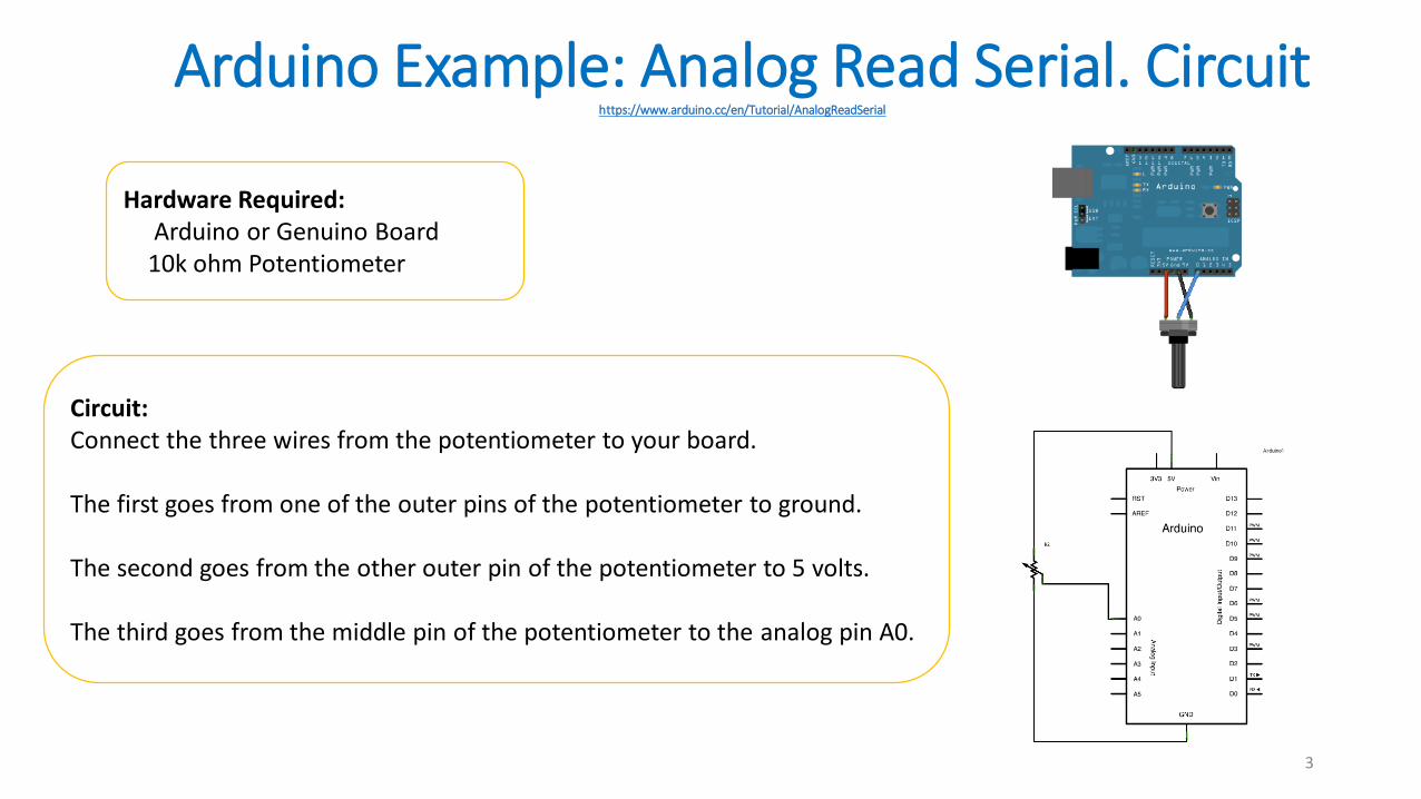
Hardware Required:Arduino or Genuino Board
10k ohm Potentiometer
Circuit:Connect the three wires from the potentiometer to your board.
The first goes from one of the outer pins of the potentiometer to ground.
The second goes from the other outer pin of the potentiometer to 5 volts.
The third goes from the middle pin of the potentiometer to the analog pin A0.
Arduino Example: Analog Read Serial. Codehttps://www.arduino.cc/en/Tutorial/AnalogReadSerial
4
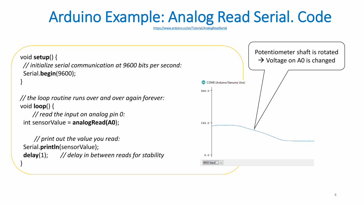
void setup() {// initialize serial communication at 9600 bits per second:Serial.begin(9600);
}
// the loop routine runs over and over again forever:void loop() {
// read the input on analog pin 0:int sensorValue = analogRead(A0);
// print out the value you read:Serial.println(sensorValue);delay(1); // delay in between reads for stability
}
Potentiometer shaft is rotated Voltage on A0 is changed
What is wrong with this code ?
5
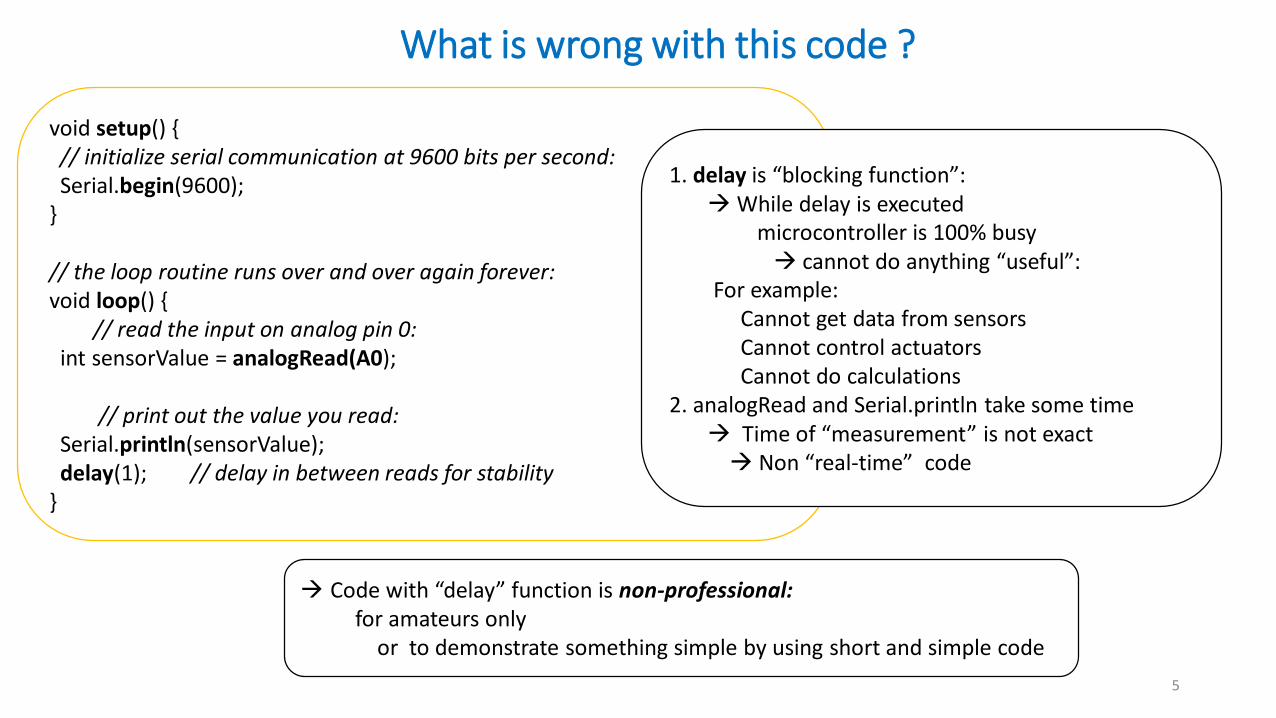
void setup() {// initialize serial communication at 9600 bits per second:Serial.begin(9600);
}
// the loop routine runs over and over again forever:void loop() {
// read the input on analog pin 0:int sensorValue = analogRead(A0);
// print out the value you read:Serial.println(sensorValue);delay(1); // delay in between reads for stability
}
1. delay is “blocking function”:While delay is executed
microcontroller is 100% busy cannot do anything “useful”:
For example:Cannot get data from sensorsCannot control actuatorsCannot do calculations
2. analogRead and Serial.println take some time Time of “measurement” is not exact Non “real-time” code
Code with “delay” function is non-professional:for amateurs only
or to demonstrate something simple by using short and simple code
Multitasking the Arduino: Using millis for timinghttps://learn.adafruit.com/multi-tasking-the-arduino-part-1/overview
6
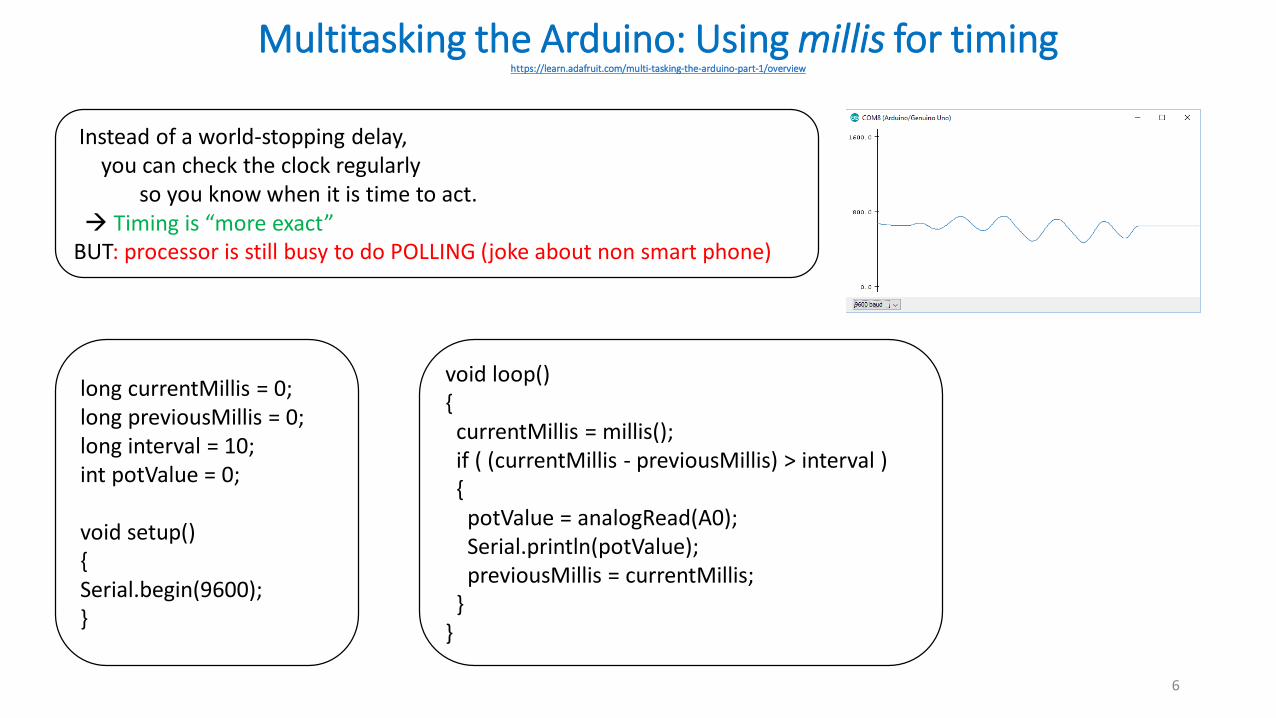
Instead of a world-stopping delay, you can check the clock regularly
so you know when it is time to act. Timing is “more exact”
BUT: processor is still busy to do POLLING (joke about non smart phone)
long currentMillis = 0;long previousMillis = 0; long interval = 10;int potValue = 0;
void setup(){Serial.begin(9600);}
void loop(){
currentMillis = millis();if ( (currentMillis - previousMillis) > interval ){
potValue = analogRead(A0);Serial.println(potValue);previousMillis = currentMillis;
} }
State Machine: Using millis for multitaskinghttps://learn.adafruit.com/multi-tasking-the-arduino-part-1/overview
7
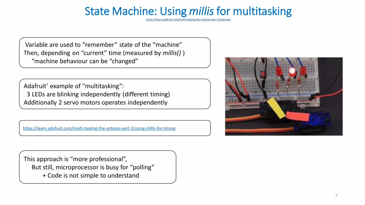
Variable are used to “remember” state of the “machine”Then, depending on “current” time (measured by millis() )
“machine behaviour can be “changed”
This approach is “more professional”,But still, microprocessor is busy for “polling”
+ Code is not simple to understand
https://learn.adafruit.com/multi-tasking-the-arduino-part-1/using-millis-for-timing
Adafruit’ example of “multitasking”:3 LEDs are blinking independently (different timing)
Additionally 2 servo motors operates independently
Using Interruptsby Multi-tasking the Arduino – Part 2
https://learn.adafruit.com/multi-tasking-the-arduino-part-2
8
INTERRUPT:An interrupt is a signal
that tells the processorto immediately stop what it is doing
and handle some high priority processing.That high priority processing is called an Interrupt Handler.
An interrupt handler is like any other void function.If you write one and attach it to an interrupt,
it will get called whenever that interrupt signal is triggered.
When you return from the interrupt handler, the processor goes back to continue what it was doing before.
Using Interruptsby Multi-tasking the Arduino – Part 2
https://learn.adafruit.com/multi-tasking-the-arduino-part-2
9
INTERRUPT:An interrupt is a signal
that tells the processorto immediately stop what it is doing
and handle some high priority processing.That high priority processing is called an Interrupt Handler.
An interrupt handler is like any other void function.If you write one and attach it to an interrupt,
it will get called whenever that interrupt signal is triggered.
When you return from the interrupt handler, the processor goes back to continue what it was doing before.
Sources of Interruptshttps://learn.adafruit.com/multi-tasking-the-arduino-part-2
10
Interrupts can be generated from several sources:Timer interrupts from one of the Arduino timers.
External Interrupts from a change in state of one of the external interrupt pins.
Pin-change interrupts from a change in state of any one of a group of pins.
Timer Interruptshttps://learn.adafruit.com/multi-tasking-the-arduino-part-2/timers
11
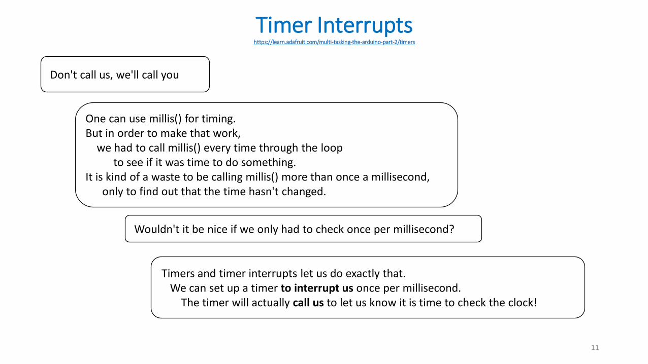
Don't call us, we'll call you
One can use millis() for timing. But in order to make that work,
we had to call millis() every time through the loopto see if it was time to do something.
It is kind of a waste to be calling millis() more than once a millisecond, only to find out that the time hasn't changed.
Wouldn't it be nice if we only had to check once per millisecond?
Timers and timer interrupts let us do exactly that. We can set up a timer to interrupt us once per millisecond.
The timer will actually call us to let us know it is time to check the clock!
Arduino Timershttps://learn.adafruit.com/multi-tasking-the-arduino-part-2/timers ; http://www.hobbytronics.co.uk/arduino-timer-interrupts
12
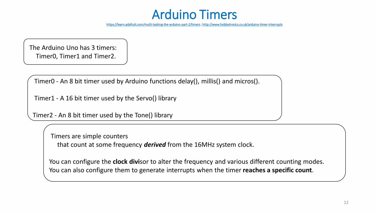
The Arduino Uno has 3 timers: Timer0, Timer1 and Timer2.
Timer0 - An 8 bit timer used by Arduino functions delay(), millis() and micros().
Timer1 - A 16 bit timer used by the Servo() library
Timer2 - An 8 bit timer used by the Tone() library
Timers are simple counters that count at some frequency derived from the 16MHz system clock.
You can configure the clock divisor to alter the frequency and various different counting modes. You can also configure them to generate interrupts when the timer reaches a specific count.
Arduino Timers. Timer0https://learn.adafruit.com/multi-tasking-the-arduino-part-2/timers
13
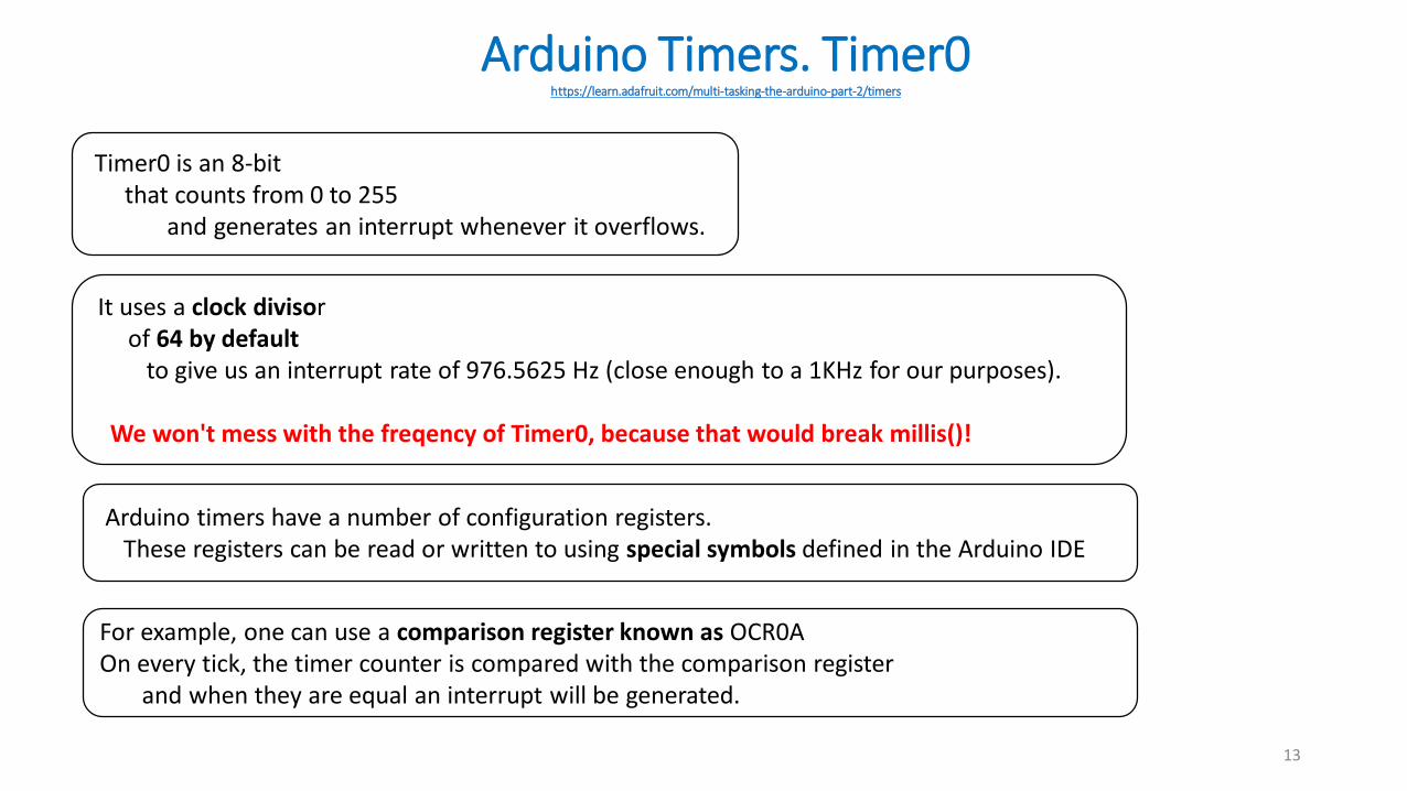
Timer0 is an 8-bit that counts from 0 to 255
and generates an interrupt whenever it overflows.
It uses a clock divisorof 64 by default
to give us an interrupt rate of 976.5625 Hz (close enough to a 1KHz for our purposes).
We won't mess with the freqency of Timer0, because that would break millis()!
Arduino timers have a number of configuration registers. These registers can be read or written to using special symbols defined in the Arduino IDE
For example, one can use a comparison register known as OCR0A On every tick, the timer counter is compared with the comparison register
and when they are equal an interrupt will be generated.
Arduino Timers. Timer1. Prescalershttp://playground.arduino.cc/Code/Timer1
14
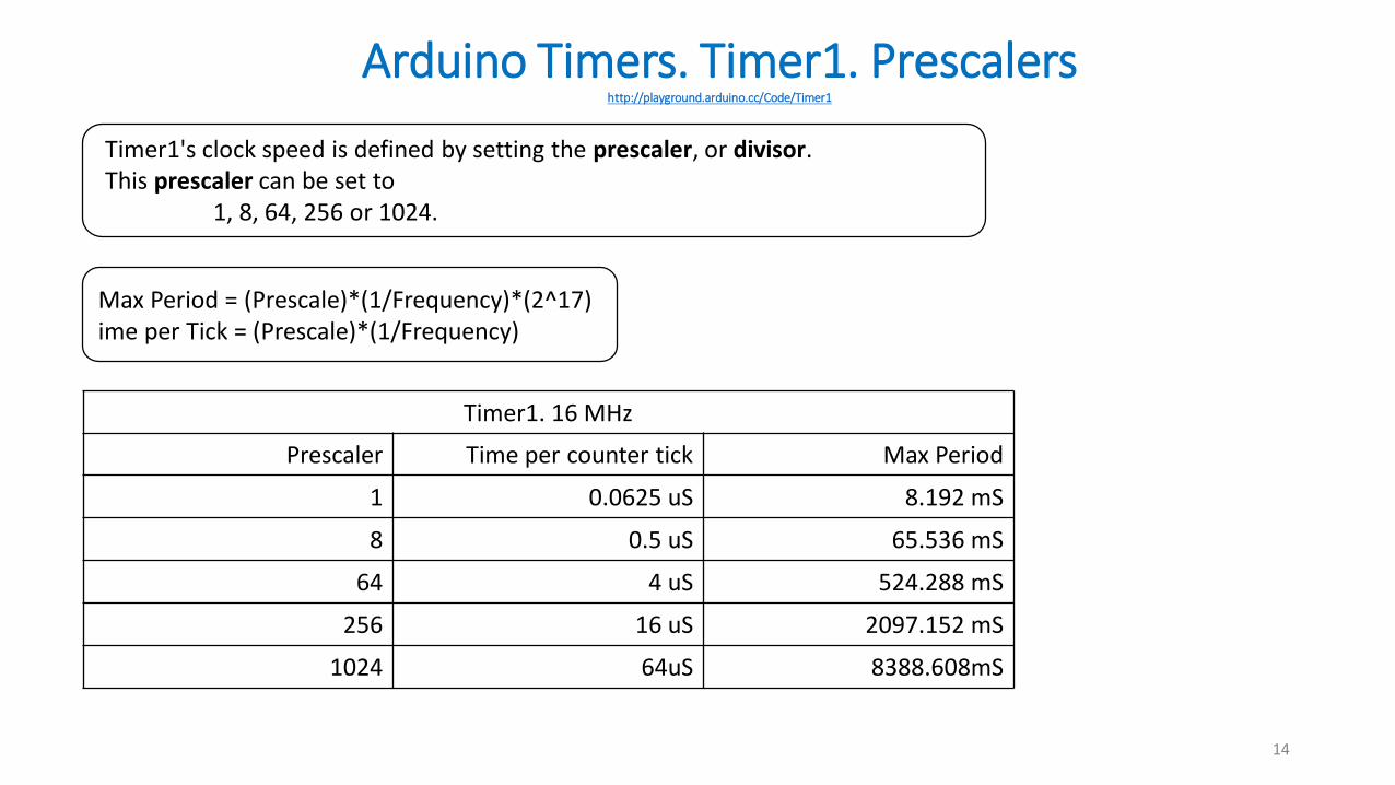
Timer1's clock speed is defined by setting the prescaler, or divisor. This prescaler can be set to
1, 8, 64, 256 or 1024.
Timer1. 16 MHz
Prescaler Time per counter tick Max Period
1 0.0625 uS 8.192 mS
8 0.5 uS 65.536 mS
64 4 uS 524.288 mS
256 16 uS 2097.152 mS
1024 64uS 8388.608mS
Max Period = (Prescale)*(1/Frequency)*(2^17)ime per Tick = (Prescale)*(1/Frequency)
Arduino Timers. Timer1http://www.hobbytronics.co.uk/arduino-timer-interrupts
15
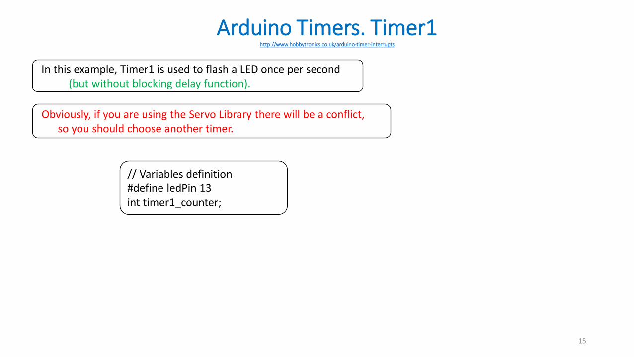
In this example, Timer1 is used to flash a LED once per second (but without blocking delay function).
Obviously, if you are using the Servo Library there will be a conflict, so you should choose another timer.
// Variables definition#define ledPin 13int timer1_counter;
Arduino Timers. Timer1. Blinking LEDhttp://www.hobbytronics.co.uk/arduino-timer-interrupts
16
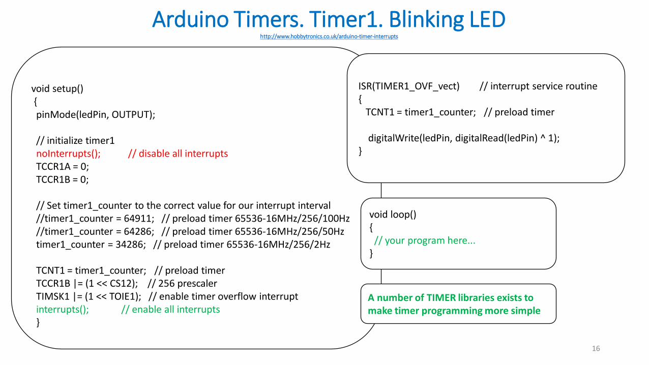
void setup(){pinMode(ledPin, OUTPUT);
// initialize timer1 noInterrupts(); // disable all interruptsTCCR1A = 0;TCCR1B = 0;
// Set timer1_counter to the correct value for our interrupt interval//timer1_counter = 64911; // preload timer 65536-16MHz/256/100Hz//timer1_counter = 64286; // preload timer 65536-16MHz/256/50Hztimer1_counter = 34286; // preload timer 65536-16MHz/256/2Hz
TCNT1 = timer1_counter; // preload timerTCCR1B |= (1 << CS12); // 256 prescalerTIMSK1 |= (1 << TOIE1); // enable timer overflow interruptinterrupts(); // enable all interrupts}
ISR(TIMER1_OVF_vect) // interrupt service routine {
TCNT1 = timer1_counter; // preload timer
digitalWrite(ledPin, digitalRead(ledPin) ^ 1);}
void loop(){// your program here...
}
A number of TIMER libraries exists to make timer programming more simple
Arduino Timers. Timer1. Analog Read Data from Sensorhttp://www.hobbytronics.co.uk/arduino-timer-interrupts
17
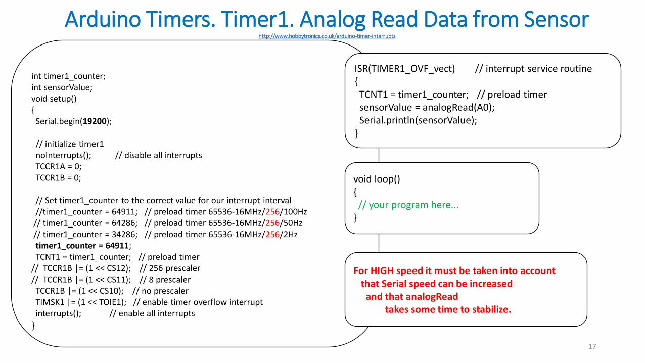
int timer1_counter;int sensorValue;void setup(){Serial.begin(19200);
// initialize timer1 noInterrupts(); // disable all interruptsTCCR1A = 0;TCCR1B = 0;
// Set timer1_counter to the correct value for our interrupt interval//timer1_counter = 64911; // preload timer 65536-16MHz/256/100Hz// timer1_counter = 64286; // preload timer 65536-16MHz/256/50Hz// timer1_counter = 34286; // preload timer 65536-16MHz/256/2Hztimer1_counter = 64911; TCNT1 = timer1_counter; // preload timer
// TCCR1B |= (1 << CS12); // 256 prescaler// TCCR1B |= (1 << CS11); // 8 prescalerTCCR1B |= (1 << CS10); // no prescalerTIMSK1 |= (1 << TOIE1); // enable timer overflow interruptinterrupts(); // enable all interrupts
}
ISR(TIMER1_OVF_vect) // interrupt service routine {TCNT1 = timer1_counter; // preload timersensorValue = analogRead(A0);Serial.println(sensorValue);
}
void loop(){// your program here...
}
For HIGH speed it must be taken into accountthat Serial speed can be increased
and that analogReadtakes some time to stabilize.

Arduino UNO. External Interrupthttps://www.arduino.cc/en/Reference/AttachInterrupt
18
Arduino UNO:2 digital pins can be used for External Interrupts
INT0 is mapped to Pin2INT1 is mapped to Pin3
(It is possible to use more pins…but in a more complex way…)
Normally you) to translate the ashould use
digitalPinToInterrupt(pinctual digital pin to the specific interrupt number.
For example, if you connect to pin 3, use digitalPinToInterrupt(3)
To use External interruptInterrupt handler must be created
and “associated” with specific pin.
This is done by using function attachinterrupt
Arduino UNO. External Interrupt MODEhttps://www.arduino.cc/en/Reference/AttachInterrupt
19
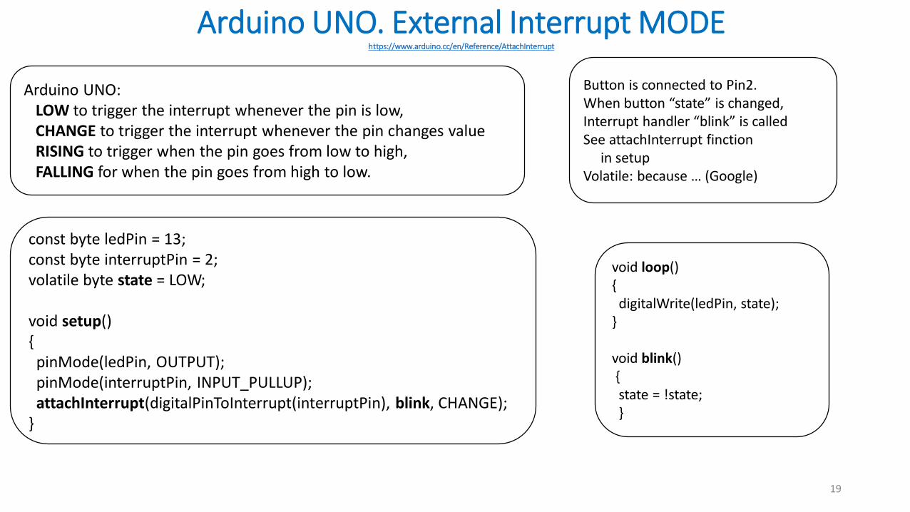
Arduino UNO:LOW to trigger the interrupt whenever the pin is low,CHANGE to trigger the interrupt whenever the pin changes valueRISING to trigger when the pin goes from low to high,FALLING for when the pin goes from high to low.
const byte ledPin = 13;const byte interruptPin = 2;volatile byte state = LOW;
void setup(){
pinMode(ledPin, OUTPUT);pinMode(interruptPin, INPUT_PULLUP);attachInterrupt(digitalPinToInterrupt(interruptPin), blink, CHANGE);
}
void loop(){digitalWrite(ledPin, state);
}
void blink(){state = !state;}
Button is connected to Pin2.When button “state” is changed,Interrupt handler “blink” is calledSee attachInterrupt finction
in setupVolatile: because … (Google)
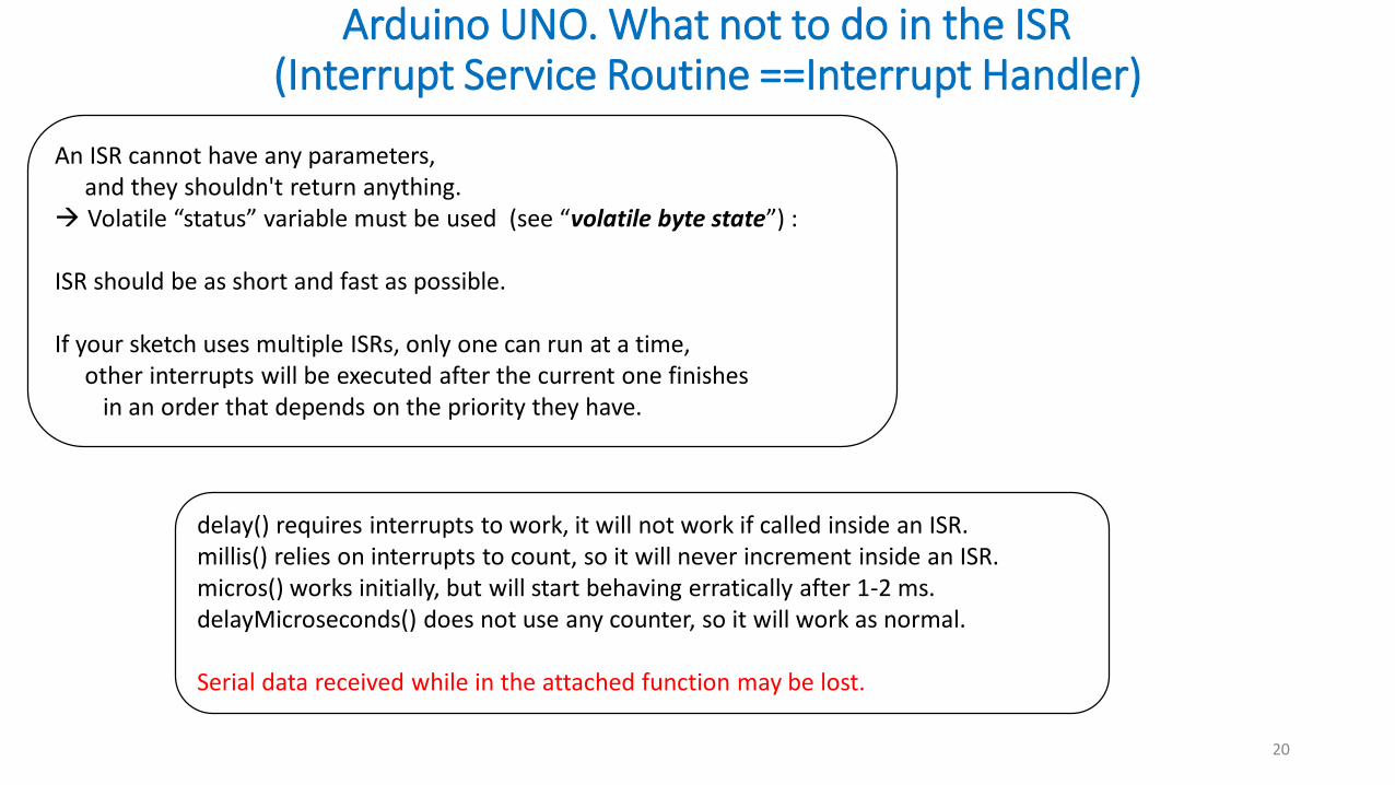
Arduino UNO. What not to do in the ISR (Interrupt Service Routine ==Interrupt Handler)
20
An ISR cannot have any parameters, and they shouldn't return anything.
Volatile “status” variable must be used (see “volatile byte state”) :
ISR should be as short and fast as possible.
If your sketch uses multiple ISRs, only one can run at a time, other interrupts will be executed after the current one finishes
in an order that depends on the priority they have.
delay() requires interrupts to work, it will not work if called inside an ISR. millis() relies on interrupts to count, so it will never increment inside an ISR. micros() works initially, but will start behaving erratically after 1-2 ms. delayMicroseconds() does not use any counter, so it will work as normal.
Serial data received while in the attached function may be lost.