Application of Frontal Polymerization to...
31
Application of Frontal Polymerization to Manufacturing of Large Crossection Composite Structures by a modified Pultrusion process ABSTRACT: This work proposes the use of steady state ascending polymerization fronts in a vertical reactor to cure thick- section composites such that heat transfer occurs axially rather than radially. Pulling the polymer from under such a front at the front velocity will retain the steady state nature of the process and the reaction front will be localized in space. A reactor configuration is proposed to produce a 100mm diameter rod of an experimental composite by frontal polymerization of a dimethacrylate monomer using thermal initiation. The process offers an energy efficient method of producing thick section composites at a practical rate. 1. INTRODUCTION: Composites A composite may be defined as a material made by combining two or more materials with distinct chemical properties in such a way that they remain macroscopally separated within the material. Composites generally consist of a matrix material which is in bulk with a filler which is the dispersed phase. Typically, the filler and matrix have different characteristic properties which combine beneficially to give the composite its unique advantages over monolithic materials such as metals, etc. Examples: Concrete, tires, plywood, etc. Fig.1.1. shows the advantages of composites over steel and aluminum. 1
Transcript of Application of Frontal Polymerization to...
Application of Frontal Polymerization to Manufacturing of Large Crossection Composite Structures by a modified Pultrusion process
ABSTRACT:
This work proposes the use of steady state ascending polymerization fronts in a vertical reactor to cure thick-section composites such that heat transfer occurs axially rather than radially. Pulling the polymer from under such a front at the front velocity will retain the steady state nature of the process and the reaction front will be localized in space. A reactor configuration is proposed to produce a 100mm diameter rod of an experimental composite by frontal polymerization of a dimethacrylate monomer using thermal initiation. The process offers an energy efficient method of producing thick section composites at a practical rate.
1. INTRODUCTION:Composites A composite may be defined as a material made by combining two or more materials with distinct chemical properties in such a way that they remain macroscopally separated within the material. Composites generally consist of a matrix material which is in bulk with a filler which is the dispersed phase. Typically, the filler and matrix have different characteristic properties which combine beneficially to give the composite its unique advantages over monolithic materials such as metals, etc. Examples: Concrete, tires, plywood, etc. Fig.1.1. shows the advantages of composites over steel and aluminum.
Fig.1.1: Comparison of composites with conventional monolithic materials [1]. Fiber Reinforced Plastics (FRP) Fiber reinforced plastics (FRP) are a class of composite materials that have become very important recently. FRP consists of a plastic (polymer) matrix which is reinforced by fibers as the filler material. The fibers used are typically glass fibers, however, boron, carbon, aramid (Kevlar), metal and ceramic fibers have been extensively used [1]. Natural fibers such as jute, sisal, coir, etc, have received much attention recently [2]. The reinforcement may be as continuous fiber rovings, as discontinuous chopped strands (whiskers), woven or non-woven mats and also as honeycombs or other core structures. The main purpose of the reinforcement is to carry the load in their longitudinal direction and provide the necessary stiffness and strength to the composite [3]. The function of the matrix is to hold the reinforcements together, providing them uniform load distribution and protect them from the environment [4]. Thermosets like epoxy, phenolics, polyesters, vinyl esters as well as thermoplastics such as polypropylene, polyamides, polyether ether ketone (PEEK) have been used as matrix materials [5].
1
Significance of FRP (Properties and Applications) FRPs are used in applications where high strength and light weight are required. They offer the benefits of high impact resistance, low thermal expansion coefficient, easy reparability and colorability. Further, the properties may be modified to produce a material with desired properties. Mechanical properties can also be tailored to reach values comparable to those of structural steel [6]. FRPs have extensive applications in civil engineering and are becoming more attractive compared to conventional materials owing to their declining cost. A 2002 review by Bakis et.al [7] provides a detailed discussion about their gaining importance in this field. They have also become a material of choice for off-shore construction [8]. Large sized ship, submarine and boat parts are constructed out of FRPs [9, 10]. In the automobile industry there is a trend towards using FRP composites in vehicle bodies [11]. Almost the entire body of the high speed racing cars of Formula-1 [12] are made from advanced composites. Also, in aviation, metals are increasingly being replaced by FRPs in wings, propellers and other body parts [13]. High strength carbon fiber composites are popular in spacecraft [14] applications. FRPs seem to be a promising material for space stations [15] and for construction in space [16]. Other applications are in furniture, harnessing wind energy [17], sport and recreational (tennis racquets, bicycles, water-slides) etc. In this proposal we are particularly interested in larger, thicker composite parts such as I-sections, planks, decks, columns, etc, which are of civil engineering interest. The applications could be in off-shore, civilian or space station construction.
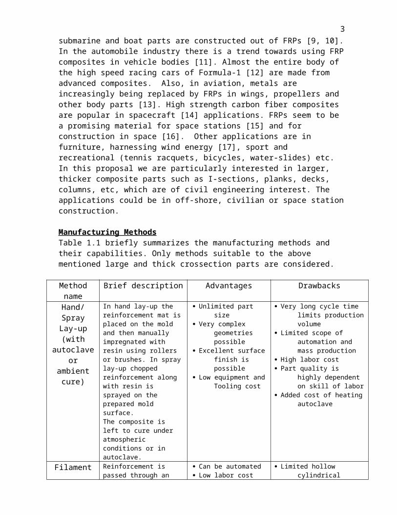
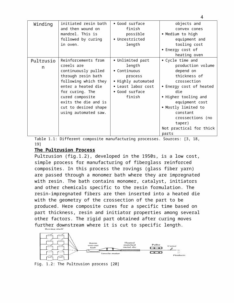
Manufacturing MethodsTable 1.1 briefly summarizes the manufacturing methods and their capabilities. Only methods suitable to the above mentioned large and thick crossection parts are considered.
Method name Brief description Advantages DrawbacksHand/Spray
Lay-up(with
autoclave or ambient cure)
In hand lay-up the reinforcement mat is placed on the mold and then manually impregnated with resin using rollers or brushes. In spray lay-up chopped reinforcement along with resin is sprayed on the prepared mold surface.The composite is left to cure under atmospheric conditions or in autoclave.
Unlimited part size Very complex geometries
possible Excellent surface finish is
possible Low equipment and
Tooling cost
Very long cycle time limits production volume
Limited scope of automation and mass production
High labor cost Part quality is highly dependent
on skill of labor Added cost of heating autoclave
Filament Winding
Reinforcement is passed through an initiated resin bath and then wound on mandrel. This is followed by curing in oven.
Can be automated Low labor cost Good surface finish
possible Unrestricted length
Limited hollow cylindrical objects and convex cones
Medium to high equipment and tooling cost
Energy cost of heating ovenPultrusion Reinforcements from creels
are continuously pulled through resin bath following which they enter a heated die for curing. The cured composite exits the die and is cut to desired shape using automated saw.
Unlimited part length Continuous process Highly automated Least labor cost Good surface finish
Cycle time and production volume depend on thickness of crossection
Energy cost of heated die Higher tooling and equipment
cost Mostly limited to constant
crossections (no taper)Not practical for thick parts
Table 1.1: Different composite manufacturing processes. Sources: [3, 18, 19]
2
The Pultrusion ProcessPultrusion (fig.1.2), developed in the 1950s, is a low cost, simple process for manufacturing of fiberglass reinforced composites. In this process the rovings (glass fiber yarn) are passed through a monomer bath where they are impregnated with resin. The bath contains monomer, catalyst, initiators and other chemicals specific to the resin formulation. The resin-impregnated fibers are then inserted into a heated die with the geometry of the crossection of the part to be produced. Here composite cures for a specific time based on part thickness, resin and initiator properties among several other factors. The rigid part obtained after curing moves further downstream where it is cut to specific length.
Fig. 1.2: The Pultrusion process [20]
The Pultrusion process is increasingly being used for the manufacture of continuous composite profiles [20-22]. Starr’s book “Pultrusion for Engineers” [19] states that this is the only “truly continuous” process for composite manufacturing. A 2002 US Patent [23] claims Pultrusion to be the most economic process for manufacturing composites. Others have mentioned the mechanical strength and flexibility of pultruded composite parts [24, 25], their superior strength to weight ratio [25] and durability [26]. In spite of it’s economic benefits and capability of high volume production pultrusion, just like other conventional composite manufacturing process has restrictions as far as crossection (thickness) of the profile is concerned [27, 28].
2. CHALLENGES IN THE MANUFACTURING OF THICK COMPOSITE PARTS:
Uneven Cure: In high temperature autoclaves as well as in pultrusion dies, the composite is heated from outside (fig.2.1). Heat penetrates into the interior of the composite. The time taken for this depends on thickness and thermal conductivity of the system. Low thermal conductivities of the fiber-resin system result in slower heat transfer to the interior of thick crossection parts [28]. If heater temperature is further raised it may lead to damage to the outer surface and thermal spiking which we will discuss next [29]. Such undercure and non-uniform cure have detrimental effects for civil engineering applications [30]. Mazumdar’s book [3] says that a 0.125 in. thick profile can be pultruded at about 3-4ft /min but a 0.75 in. thick section can only be produced at around 9in./min.
Fig 2.1: Curing in conventional composite manufacturing process is by heat transfer from exterior to interior
Ramakrishnan et.al [31] have stated that these “differential cure rates” present a greater challenge for thick composites and lead to poor structural properties and also that the solution of microwave curing only reduces the problem but does not eliminate it.
3
Kim and White have claimed that if the exterior cures before the interior it could lead to non-uniform fiber distribution and void formation inside the composite [32] . A 1984 G. E. Patent [33] also states that non-uniform cure may lead to delamination or warpage in case of thick tape pultrusion. Fig.2.2 shows that as the pultruded part becomes thicker, the center does not reach required temperature and remains uncured as it exits the die.
Fig. 2.2: As thickness increases interior temperature lags behind surface temperature. Temperature at center vs. die position for Ny6/ATBN composites (left). As thickness increases, the degree of cure of the interior decreases. Extent of reaction at center vs. die position (right). Pultrudate thicknesses of a) 0.329cm (b) 0.658 cm (c) 0.987 cm (d) 1.316cm and (e) 1.645 cm. Pulling rate of 25 cm/min and die temperature of 195°C [34]
Fig 2.3: Degree of cure at center is lower than at outer surface. Predicted cure profiles for graphite/epoxy and fiberglass/epoxy systems at die exit in a 3/8” circular die with pull speed of 12”/min [35].
It is clear from Fig 2.3. that for higher resin content, the difference in degree of cure increases. The die in the above case is only 3/8” diameter. If the die diameter was larger this gradient would be much greater.Uneven cure occurs if heating time is insufficient and is a common problem in pultrusion.Thermal Spiking: Due to the low thermal conductivity, heat travels slowly from exterior to interior. For thick composites, by the time the interior heats up and begins to cure, the exterior has already been cured into a hard mass. The exothermic nature of curing leads to heat release and this heat stays trapped in the interior since composites are generally designed to have low thermal conductivity. This promotes very high heat buildup in the interior and may consequently result in temperatures higher than the thermal degradation temperatures of the matrix [36] which affects the physical properties significantly [27, 32].
Fig. 2.4: Thermal spikes. The center point node of glass/polyester plate of 2.54 cm thickness [37] (left); The center temperature is about 40°C above MRC (Manufacturer recommended cure temperature) (right) [38]
4
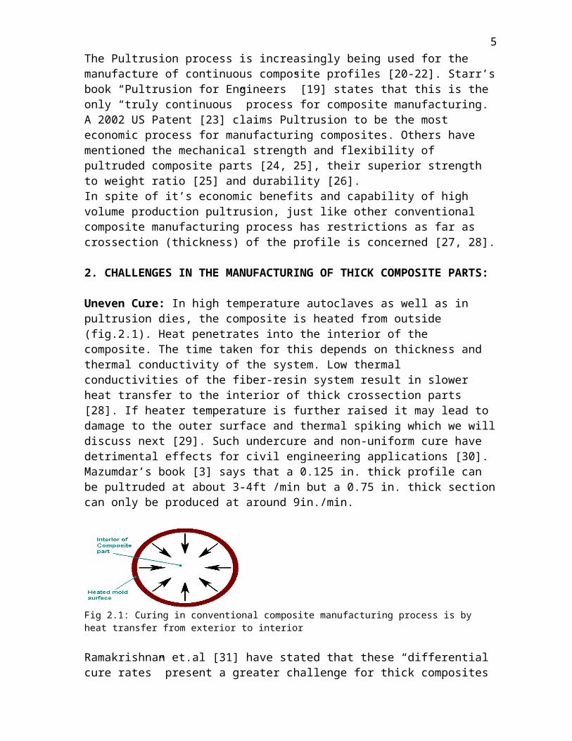
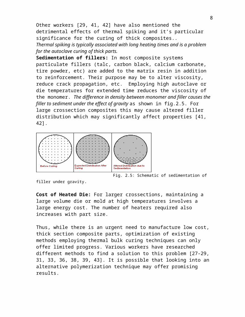
Fig.2.4 shows that the temperature at the center jumped about 40°C above the temperature of the autoclave due to exotherm from the curing reaction. Parthasarathy [38] and Mallick [39] have worked to control thermal spiking in their respective works. Kosar and Gomzi’s model for curing of polyester [40] claims that higher initiator concentration increases the magnitude of the spike.Other workers [29, 41, 42] have also mentioned the detrimental effects of thermal spiking and it’s particular significance for the curing of thick composites..Thermal spiking is typically associated with long heating times and is a problem for the autoclave curing of thick parts.Sedimentation of fillers: In most composite systems particulate fillers (talc, carbon black, calcium carbonate, tire powder, etc) are added to the matrix resin in addition to reinforcement. Their purpose may be to alter viscosity, reduce crack propagation, etc. Employing high autoclave or die temperatures for extended time reduces the viscosity of the monomer. The difference in density between monomer and filler causes the filler to sediment under the effect of gravity as shown in fig.2.5. For large crossection composites this may cause altered filler distribution which may significantly affect properties [41, 42].
Fig. 2.5: Schematic of sedimentation of filler under gravity.
Cost of Heated Die: For larger crossections, maintaining a large volume die or mold at high temperatures involves a large energy cost. The number of heaters required also increases with part size.
Thus, while there is an urgent need to manufacture low cost, thick section composite parts, optimization of existing methods employing thermal bulk curing techniques can only offer limited progress. Various workers have researched different methods to find a solution to this problem [27-29, 31, 33, 36, 38, 39, 43]. It is possible that looking into an alternative polymerization technique may offer promising results.
3. FRONTAL POLYMERIZATIONFrontal Polymerization was first carried out in 1972 in the erstwhile Soviet Union when Chechilo and Enikolopyan extended the approach of ‘Self-propagating High temperature Synthesis’ (SHS) to the polymerization of methyl methacrylate under high pressure. The mechanism used was free radical polymerization and high pressure was required to suppress instabilities and the boiling of monomer. Polymerization reactions are highly exothermic in nature [44, 45]. When heat is supplied at one end of the reactor, the polymerization reaction that is initiated locally generates sufficient heat to heat the next monomer layer and when this layer polymerizes, the exothermic heat initiates polymerization in the following layer and so on. Thus, a localized reaction zone or ‘front’ propagates throughout the reactor [46]. John A. Pojman, one of the pioneering investigators in the field defines frontal polymerization as “a mode of converting monomer into polymer via a localized reaction zone that propagates through the
5

coupling of the heat released by the reaction and thermal diffusion” [47]. Frontal polymerization (FP) is a self-propagating, autocatalytic reaction and the front maybe considered to be a ‘liquid flame’ that burns the monomer and leaves behind a trail of polymer. The process maybe thought of as analogous to the burning of a cigarette.
Fig. 3.1: Schematic of frontal polymerization with a descending front [44] Fig.3.1 shows a descending polymerization front in a test tube. There is a layer-to-layer transfer of heat, resulting in a polymerization front.
Necessary conditions for FP [41, 44]:- relatively high boiling point of monomer- high activation energy- low rate of reaction at ambient temperature (so as to prevent bulk polymerization)
and high rate at front temperature - rate of heat release at front temperature should exceed rate of heat loss from system
(i.e.) exothermic energy from the reaction must be able to support the reaction front.
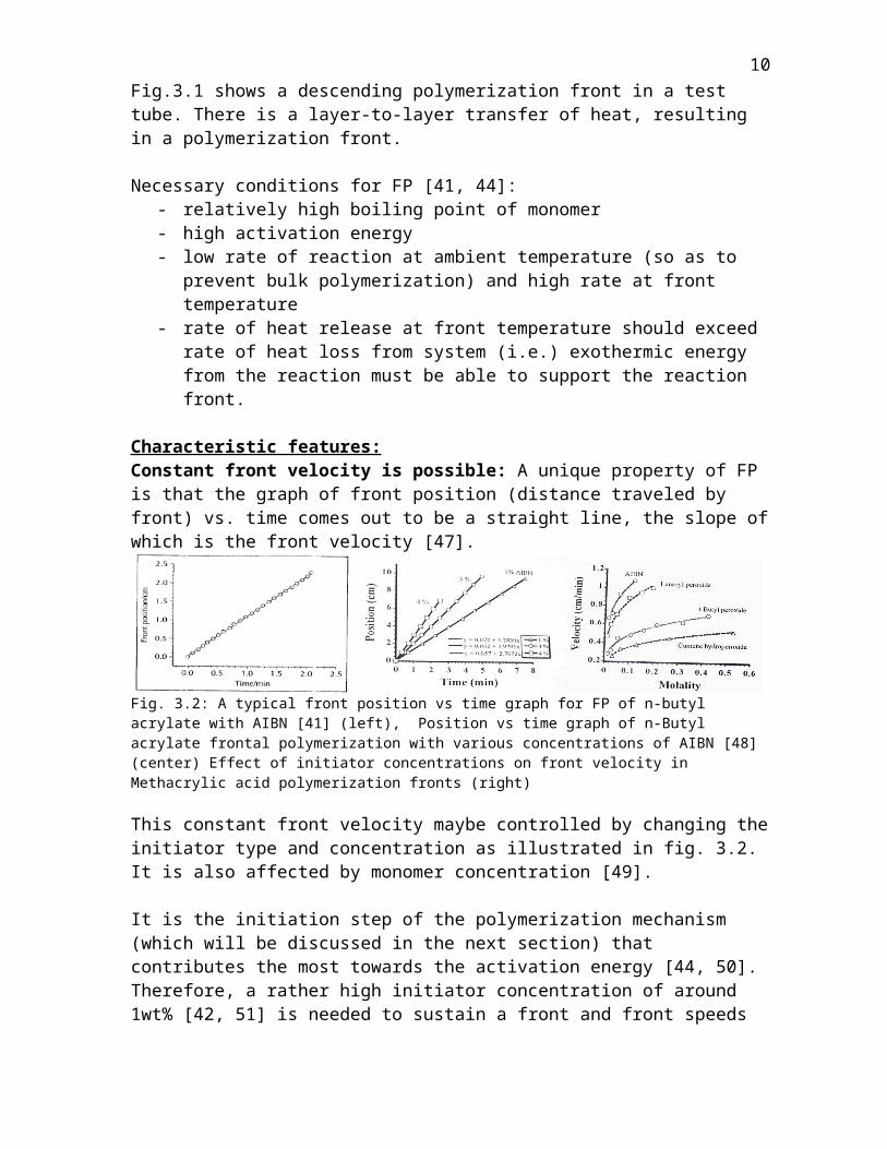
Characteristic features:Constant front velocity is possible: A unique property of FP is that the graph of front position (distance traveled by front) vs. time comes out to be a straight line, the slope of which is the front velocity [47].
Fig. 3.2: A typical front position vs time graph for FP of n-butyl acrylate with AIBN [41] (left), Position vs time graph of n-Butyl acrylate frontal polymerization with various concentrations of AIBN [48] (center) Effect of initiator concentrations on front velocity in Methacrylic acid polymerization fronts (right)
This constant front velocity maybe controlled by changing the initiator type and concentration as illustrated in fig. 3.2. It is also affected by monomer concentration [49].
6

It is the initiation step of the polymerization mechanism (which will be discussed in the next section) that contributes the most towards the activation energy [44, 50]. Therefore, a rather high initiator concentration of around 1wt% [42, 51] is needed to sustain a front and front speeds are of the order of a cm/min. Front velocities are often power functions of initiator concentration [44].Huh [52] also found that front velocity is affected by type of monomer and tube diameter. Pojman studied the effect of tube rotation [53] and unreacted monomer density [54] and Barleko [55] showed that addition of filler also plays a role.Characteristic temperature profile: After external heat is supplied and a short induction period during which the initial layer of monomer polymerizes, the temperature suddenly rises by up to 200°C within a few mm [56]. Hu et.al [57] state that the observation of such characteristic temperature profile is a way to verify that pure FP is occurring and that the process is not accompanied by any bulk polymerization. Front temperatures may be as high as 200-220°C for free radical polymerization of vinyl monomers [58], especially acrylates but temperatures as low as 63°C have been observed for urethane-acrylate polymerization [57].
Fig. 3.4: Characteristic temperature profile for FP. Polymerization of Unsaturated polymester resin with 30 wt% styrene with 2 mol% BPO. [59]
Easy Visualization: Because of difference in refractive index between monomer and polymer a clear boundary between unpolymerized and polymerized material is seen, at least in a case of transparent materials [44, 56]. Also, Pojman et.al have used bromophenol-blue, a free-radical scavenging dye to monitor the front [60]. Such dyes help identify monomer from polymer by naked eye. This method is now becoming a popular to monitor fronts [61] and can be seen in fig.3.5 (right).
Fig. 3.5: Images of descending front of TEGDMA [62] (left) and descending front of HDDA using bromophenol-blue [61] (right)
Direction of Propagation: Polymerization fronts can be generated by heating the top layer of the monomer in a cylindrical reactor in which case the fronts are descending. This is the most studied case. By suspending photoinitiators in the center of a highly viscous monomer mixture and exposing to UV light, Pojman et.al have also created spherically propagating fronts [62].The front may also be allowed to propagate in an ascending manner (i.e.) by supplying heat from the bottom of the reactor. In this case buoyancy-driven convection from the unreacted monomer may act to extinguish the front. Convection also acts to quench horizontally propagating fronts [56]. However, ascending fronts have been successfully exploited in material synthesis [29, 47, 63] and mathematical modeling works [64, 65] have been devoted to this case.
7
Thermal or Photoinitiation: In order to generate a polymerization front an energy input is required to initiate the front. Such energy maybe supplied in the form of heat (i.e.) thermal initiation or light (i.e.) photoinitiation. Thermal initiation in experimental FP systems is commonly done by using a soldering iron. A hot plate may also be used for thermal initiation. Light for photoinitiation maybe supplied either as visible light of known wavelength as is common in curing of dental composites or from a UV lamp. Nason et.al have used photoinitiation for FP of various acrylates [66] and Cabral et.al [67] used UV initiated FP for microfluidic applications. Although photoinitiation eliminates requirement of high temperature for initiation it requires the system to be transparent to light.
Mechanism of Frontal Polymerization:Our discussion will be limited to the best studied free radical polymerization process. Washington and Steinbock’s review [44] claims that frontal polymerizations with free-radical initiators proceed in a similar fashion as conventional free-radical polymerization with the exception of the localization of reaction zone leading to the control of synthesis temperature. An in depth discussion of free-radical polymerization is provided in chapter 3 of Odian’s book “Principles of Polymerization” [45].Frontal free-radical polymerization proceeds in three major steps as follows:Initiation: This step comprises of two reactions. When energy is supplied in the form of heat or light the initiator molecule undergoes homolytic dissociation to form two free-radicals. I 2f R• This is followed by the addition of radical to a monomer molecule to form a monomer radical.R• + M M1• Since the dissociation step is rate determining the initiation rate is given as:Ri = 2 f kd [I] where f is initiator efficiency, [I] is initiator concentration and kd is rate constant for dissociation reaction.By Arrhenius law, kd = Ad exp(-Ed/ RTa) where Ad is frequency factor and Ed is activation energy for the initiator dissociation reaction, R is gas constant and Ta = ambient monomer temperature Propagation: The monomer radical then combines with another monomer molecule producing a radical that is larger than the previous one by the molar mass of one monomer molecule. This step repeats successively. In this manner monomer molecules add onto the radical site, eventually leading to a growing polymer chain. This is the heat producing step.
M1• + M M2•
M2• + M M3•
and so on.
Mn• + M Mn+1• Thus, the propagation rate is given as:Rp = kp [M] [M•] where [M] is the monomer concentration and [M•] is the total concentration of all radicals of size M1
• or larger. kp is the polymerization rate constant given by Arrhenius law as:kp = Ap exp(-Ep/ RTa) where Ap is the frequency factor and Ep is the activation energy for the propagation reaction.
8
kd
ki
kp
kp
kp

Termination: When a growing polymer chain meets another chain or a dissociated radical, the radical sites form a σ bond, thus forming a polymer molecule which cannot grow further. This is called termination by coupling. Termination may also occur by chain transfer (hydrogen abstraction) in which case one of the polymer molecules ends up with a double bond at one end.
Mm• + Mn• Mm+n (polymer) Thus, in a simplified and relevant case where termination is exclusively by coupling, the rate of termination maybe given as:Rt = 2 kt [M•]2 or [M•] = (Rt/2 kt)1/2
Investigators have considered frontal polymerization to be a ‘steady state’ or at least a ‘quasi steady state’ process for the purpose of mathematical modeling [46, 68-71]. This assumption implies that rate of change of radical concentration in the system does not change [45]. Applying the steady state assumption,Ri = Rt, which on substituting into the propagation rate equation gives:Rp = kp [M] (f kd [I] / kt)1/2
The above equation gives the propagation rate for free-radical frontal polymerization. Thus, it is the propagation step that produces the major heat release required for self propagation. The composite or effective activation energy for the entire polymerization process is given by [45]:Eeff = Ep + Ed/2 – Et/2 where Ep, Ed and Et are activation energies of propagation, initiator dissociation and termination respectively. However, it is the initiator dissociation part of the initiation step that ensures a polymerization front [72] since there is a significant difference in reaction rate between reaction zone and unreacted zone. This is because the second term Ed is the largest in magnitude of all the three terms in the right hand side of the above equation [44, 50]. This also explains why the initiator concentration has such a significant influence on the front’s existence, front speed and temperature profile.To maintain a localized reaction front the exothermic heat generated by the propagation step during polymerization of one layer of monomer must be sufficient to induce initiator dissociation in the next layer of same size.
A simple heat balance in the primary heat generating propagation step gives the equation: ρ Cp (∂T/ ∂t) = λ (∂2T/ ∂x2) + (-∆HR) [I]1/2 [M] Ap exp(-Ep/ RTa) The left hand term is the heat required to raise the next layer of monomer to the front temperature. The first term on the right hand side represents conductive heat flux through the polymer whereas the last term represents heat generation from curing. Here ρ is the average value of density, Cp is specific heat of monomer, λ is thermal conductivity, ∆HR is the heat of the propagation reaction. The above equation is written in different ways in various mathematical modeling works [29, 64, 69-71, 73] and is the basic step assumed in all the analyses. It does not consider heat losses in the reactor.
Jeszenszky [74] and Garbey [64] have provided expressions for front velocity but neither explains the effect of initiator concentration on front velocity.Comissiong [69] derived an equation for adiabatic front propagation velocity. This maybe written asu2 = κ R T a2 [I] 1/2 Ap exp (-Ep/ RTa) q M Ed
9
kt
where κ is thermal diffusivity given by λ/ ρCp ,q is rise in temperature induced per unit of reacted monomer given by (-∆HR)/ρCp [71]Ta is the adiabatic final temperature given by T0 + qM ( T0 is ambient temperature or temperature of monomer) M is monomer concentration, I is initiator concentration.The above equation involves parameters relating to the polymerization process and shows that front speed increases with initiator concentration as has been proved. It is an equation for front speed taking into account complete conversion, which is desirable in our case. We shall use this equation in our numerical analysis section.Polymerization fronts may not always propagate as simple planar fronts [50, 75]. However, our interest is limited to steady state planar front propagation for material synthesis. The stability of polymerization fronts is decided by the Zeldovich number given byZ = Ta – T0 Eeff__ Ta RTaWhen Z < Zcr = 8.4 planar mode is stableWhen Z > Zcr = 8.4 planar mode is unstable [62, 76]We shall use this criterion to check the stability of a planar front in mathematical analysis.Bowden et.al [73] have provided an expression for the critical viscosity of the monomer system under which ascending polymerization fronts become unstable. νc = g β q κ 2 _ 5 u3 + 40 (2π κ/ D)2 uWhere g is acceleration due to gravity, β is the coefficient of thermal expansion, u is front velocity and D is the diameter of reactor. When system viscosity exceeds νc a stable, planar ascending front is observed [73].
4. METHOD SELECTIONFrontal polymerization offers the choice of direction of propagation and also initiation method and to design a process for continuous production of thick composite the correct conditions have to be selected carefully. We shall design our unit to fabricate a composite cylinder of about 100mm diameter and 0.5m length.Selection of Thermal Initiator: The problem with photoinitiation is that the method requires the system to be transparent or at least permeable to UV radiation. Growing concerns regarding the health and safety of workers exposed to radiation make this choice even less attractive [77, 78]. These considerations lead us to select thermal initiation over photoinitiation.Several thermal initiators of different activation energies are available. Conventional free-radical initiators such as peroxides and nitriles produce gaseous products upon thermal decomposition [72]. These bubbles affect kinetic studies of front parameters and more importantly are responsible for inhomogenities and voids in the product [61] which are highly undesirable in case of a high quality composite material. To eliminate such bubbles earlier investigators used high pressure reactors and recently researchers have used persulfate initiators in their studies [57, 61]. However, commonly available persulfate initiators are insoluble or sparingly soluble in organic media. To counter this problem Masere [79] has invented gas-free initiators which are soluble in organic monomers . One of these products tricaprylmethylammonium (Aliquat) persulfate (APSO) has shown good solubility in organic monomers without producing color. It has an Ed value of 148 kJ mol-1 which is comparable to that of commercial peroxide and nitrile initiators. Further, it supports frontal polymerization in acrylic monomers. Selection of Ascending Front: Spherical fronts are eliminated due to the fact that they are possible in only specific systems and so far only with photoinitiation. Horizontal FP fronts
10

have been proposed in a pultrusion process by Pojman et.al [41] but this would mean that for a thick composite, if curing is not quick enough or if resin viscosity is relatively low, sedimentation may occur in the time the pultrudate travels from resin bath to mold. Descending fronts suffer from fingering due to Rayleigh-Taylor instability [41, 72]. Additionally, there will always the question of supplying monomer and reinforcement at the same time to a vertical tubular reactor from under the polymer.
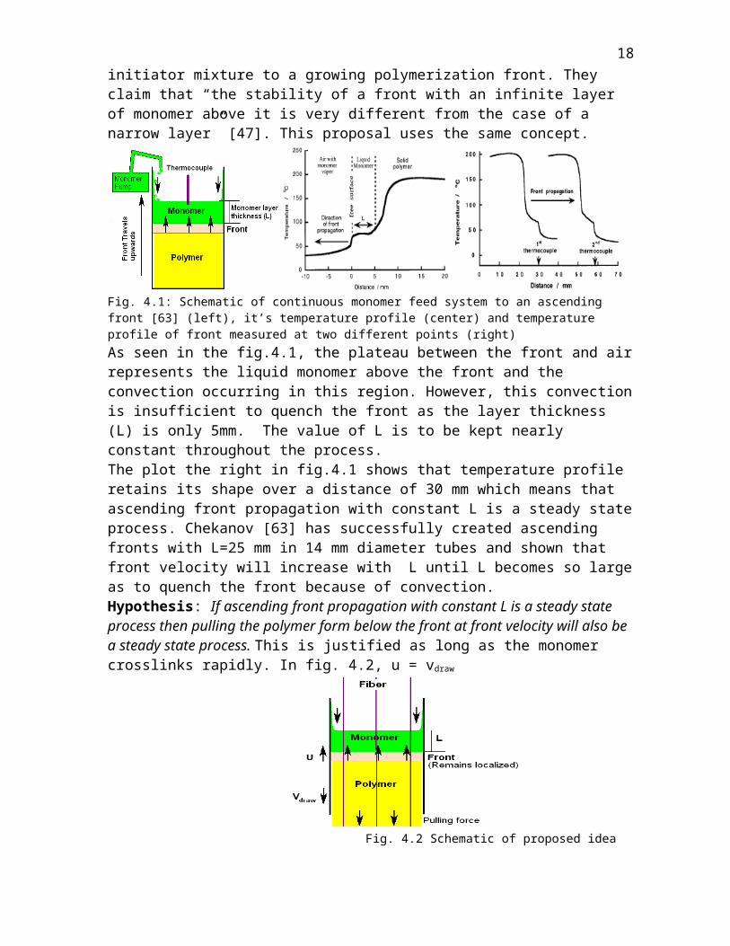
Ascending fronts are subject to convection due to which exothermic heat from below may serve to heat up the entire unreacted monomer instead of just a localized zone. This is a significant challenge but the problem can be overcome by reducing the size of the unreacted monomer layer. Chekanov [63] has managed this by controlling supply of monomer-initiator mixture to a growing polymerization front. They claim that “the stability of a front with an infinite layer of monomer above it is very different from the case of a narrow layer” [47]. This proposal uses the same concept.
Fig. 4.1: Schematic of continuous monomer feed system to an ascending front [63] (left), it’s temperature profile (center) and temperature profile of front measured at two different points (right)As seen in the fig.4.1, the plateau between the front and air represents the liquid monomer above the front and the convection occurring in this region. However, this convection is insufficient to quench the front as the layer thickness (L) is only 5mm. The value of L is to be kept nearly constant throughout the process.The plot the right in fig.4.1 shows that temperature profile retains its shape over a distance of 30 mm which means that ascending front propagation with constant L is a steady state process. Chekanov [63] has successfully created ascending fronts with L=25 mm in 14 mm diameter tubes and shown that front velocity will increase with L until L becomes so large as to quench the front because of convection.Hypothesis: If ascending front propagation with constant L is a steady state process then pulling the polymer form below the front at front velocity will also be a steady state process. This is justified as long as the monomer crosslinks rapidly. In fig. 4.2, u = vdraw
Fig. 4.2 Schematic of proposed ideaSelection of TEGDMA Monomer: Here we shall restrict ourselves to a high boiling monomer that has been shown to support polymerization fronts and also polymerizes to
11

produce a high strength matrix for composite materials. Triethylene glycol dimethacrylate (TEGDMA), a crosslinking diacrylate satisfies these requirements since it supports ascending fronts [72] and has been used in pultrusion [80]. It’s boiling point is 170-172 °C at 5 mmHg, density is 1.092 g/mL at 25 °C [81] and viscosity is 11 centipoise at 25 °C [82]. Upon polymerization the homopolymer has a Tg of about 97 °C, tensile strength of 235kgf/cm2 and compressive strength of 1500kgf/cm2 (about 150 MPa which is roughly 37% of the value for structural steel) [83]. TEGDMA shows a volumetric shrinkage of about 12wt% upon polymerization [84]. Further, our chosen thermal initiator, APSO is quite soluble in dimethacrylates. Chekanov et.al have used this system in their study [63].
5. PROCESS DESIGNReactor and Equipment description: The reactor to be used is a thick walled glass tube of 100mm internal diameter that is open at both ends. A lip will be provided at the upper end so that the monomer can be fed into the front without causing unnecessary turbulence. The length of the tube from the bottom to the lip maybe fixed at 600mm.At a distance of 20mm from the bottom end of the glass tube a 0.5mm hole will be drilled in order to fit a thermocouple. After fitting the thermocouple such that the probe does not protrude any more than 2mm from the hole, it may be sealed back with adhesive. 16 such holes are to be drilled at a distance of 20mm from center to center. The lower end of the glass tube is to be attached to a shallow copper vessel of 100mm internal diameter with a thin bottom and an undercut at the top. An O-ring gasket will prevent leakage of monomer between the glass tube and the copper vessel. The first thermocouple is fitted between the O-ring and glass. The copper vessel should have a depth of no more than 10mm from the bottom surface to the undercut. It will be fitted with two pairs of support rods with collars at the end so that they can be fixed on vertical column stands with lock pins. To simplify the attachment of fibers, their ends maybe tied to a steel net of nearly the same diameter as the bottom of the copper vessel and the net maybe either fitted to a slot or welded at the bottom. The copper vessel actually has a two part construction for easier machining and to reduce cost as shown in Fig.5.1. Only the bottom plate (Part 2) needs to be made of copper and the outer ring (Part1) maybe machined from steel or a lower thermal conductivity metal. The two are fitted with screw threads. For sake of brevity, the entire assembly of Part 1 and Part 2 (fig.5.1) is referred to as ‘copper vessel’.
Fig. 5.1: Schematic of the copper vessel and junction of glass reactor
Any standard hot plate with temperature calibration and two vertical column stands (similar to burette stands) fitted at the sides can be used. The column stands should have holes to accommodate lock pins.Equipment:
12
Fig. 5.2: A schematic of each step of the process for thick crossection composite production
13
Operation: Pre-initiation: The equipment is initially set up as shown in the pre-initiation step (Fig 5.2). The monomer is filled up to an experimentally predetermined level of height L (>40 mm) from the surface of the copper vessel. The copper vessel at this point is supported on its supports using lock pins. It is not in contact with the hot plate’s column stands. The hot-plate is heated to the predetermined ignition temperature and is lifted to meet the bottom of the copper vessel. This is the end of the pre-initiation part and beginning of initiation. Initiation: During this phase heat transfer takes place from the hot plate to the resin through the thin bottom surface of the copper vessel. After a short induction period (known experimentally), the front is generated and begins to propagate at constant speed. Since frontal polymerization is highly exothermic, temperature gradient of over 100°C is created over a span of 5mm. When initiation begins, the copper plate is freed from its own supports and is manually fitted onto the column stands on the hot plate using lock pins.As soon as the first thermocouple (T1) located at the junction of the glass reactor and copper vessel detects a temperature of 100°C (assuming ignition temperature is higher), the operating program instantly reads this value and starts a timer. Also it instructs the valve to open and allow monomer to flow at a default flow rate which is set at the estimated front velocity based on earlier experiments. The hot plate is manually switched off at this point. When the second thermocouple (T2) detects a temperature gradient of 100°C between its junctions, the program reads the timer and since all thermocouples are positioned 20mm apart the front speed (u1) is calculated. The program then adjusts the valve actuator according to the front speed (u1). When T3 detects 100°C front speed u2 is calculated by averaging u1 and the speed between T2 and T3. The valve actuator is then re-adjusted to feed at speed u2. u3 is the average of u1, u2 and the speed between T3 and T4. This averaging method ensures that the thickness of the unreacted monomer layer ‘L’ is kept constant based on the front speed and that sudden changes in front speed (due to turbulence or local inhomogenities) do not affect L. The averaging continues over the first 7 thermocouples until u6 is obtained. Pultrusion: As soon as T7 detects 100°C and u6 is calculated, the program, in addition to adjusting the feed rate from the valve actuator, sends instructions to the motion controller of the pulling mechanism. This drives the DC step motor to run at a specific rpm at which (based on the lead of the screw), the carriage moves downward at the speed of u8 and carries the hot plate and the copper vessel with it. If the front does move ahead to T8, the program detects the new speed u7 (>u6) and increases both the feed rate and drawing rate. Since the front is steady state it should eventually stop advancing as the formed polymer is drawn downwards. The program attempts to localize the front over the distance of the next 5 thermocouples (T9 to T13) or 100mm. The purpose of the next two thermocouples is to push the front down. Ideally the front should not reach T14. However, if T14 does detect 100°C the program instructs the motion controller to pull at 1.5 times the front speed (u13) until it reaches T10. If T15 detects the front the pulling mechanism draws the polymer at twice the front speed until it reaches T10.T16 is the final thermocouple and ensures process safety. If the front crosses this thermocouple the program cuts off monomer feed and eventually kills the front. Thermocouple System: The purpose of each thermocouple is to provide a temperature input to the computer program which assimilates the inputs from a given set of them and converts it into front speed. In order to minimize the size of the drill hole on the glass reactor the thinnest thermocouples are needed. K-type thermocouples have been commonly used by most workers to read front temperature. Thermocouple: Omega 5TC-TT-(K)-30-(36) x16 units - 0.25mm probe, PFA insulated [85]
14
Interface: Omega OMB-DAQ-56 - 20 channel i/p, artificial ice point, USB connectivity[86]Valves and Feed Control: The unreacted monomer sits in a tank above the glass reactor. A pipe feeds the monomer into the reactor using gravity. Since it is necessary to maintain a constant layer of unreacted monomer of thickness “L” above the front, it is desirable to use valves that can control the flow-rate of monomer through the pipe. The valve in will control the size of the pipe orifice through which the monomer system flows under gravity.Electronically Controlled Proportioning Valves: Omega PV14-B – DC step motor [87].Process Controller: Omega CNi 1652 - PID control [88] Pulling Mechanism: A lead screw slide with a rotating screw and a moving carriage is selected as the pulling mechanism. The DC step motor is directly coupled to the shaft.Lead Screw Slide: Kerk RGS10100 (Rapid Guide Screw) – 1000mm maximum travel [89]Guide Rail: Kerk RGS 10T – linear guide [90]DC Step Motor: Slo-Syn M06 – NEMA 23 type Motion Controller: Slo-Syn SS2000 Pci
6. EXPERIMENTAL PART:Before investing in any equipment to pultrude composites certain parameters of the ascending frontal polymerization system with TEGDMA monomer and thermal initiation maybe determined experimentally. A standard sized 1000mL glass beaker has roughly a 100mm diameter and a flat bottom and should be adequate. It should be calibrated on length scale in mm. The monomer system may be designed by mixing 5wt% initiator with TEGDMA. The required amount of fiber rovings maybe substituted for by adding particulate fillers. If 50vol% filler is required in the composite then particulate filler like Cab-O-Sil (an untreated micron sized fumed silica of density = 0.037 kg/L) maybe added. The weight fraction to volume fraction conversion may be done using the formulae:
Filler volume fraction = [1+ density of filler( 1/wt fraction of filler - 1)/density of resin]-1
Filler weight fraction = __density of filler x filler volume fraction _ [density of resin +(density of filler – density of resin)x filler volume fraction]
Effect of Ignition Temperature on Induction Period: Knowledge of this parameter enables us to set our hot plate temperature for the initiation step. A 40 mm thick layer of monomer system is placed in the 1000mL beaker. The hot plate is heated to a specific ignition temperature (say 100°C) and the beaker is placed on it when that temperature is reached. If a front is observed within 3 min then temperature and induction period are noted. Then the hot plate is set to a temperature 20°C higher than the previous experiment and the process is repeated. The experiment is continued until a front is observed. A curve of ignition temperature vs induction period will be obtained. Induction period is expected to decrease with temperature.Effect of Monomer layer thickness “L” on Front Speed: Although front speeds can be predicted within an order of magnitude by calculation, lack of precise knowledge of parameter values, the assumption of infinite tube diameter in formulas and the effect of heat losses may greatly affect front speed. Knowledge of front speed should be as accurate as possible since a default front speed has to be provided to the computer program.The hot plate will be heated to ignition temperature for all cases in this experiment. A 40mm thick monomer layer (L = 40 mm) will be placed in the 1000mL (with length calibration) beaker and as soon as front is observed, it’s progress will be recorded with a video camera. The experiment will be repeated with L= 50, 60, 70 and 80mm.
15

According to Chekanov, the front will either adjust it’s speed to the L value or just not propagate [63]. By careful observation of the videotapes, the most stable, planar front which propagates the fastest will be chosen. Thus, we can experimentally determine the vital parameters of ‘L’ and ‘front speed’.
7. MATHEMATICAL ANALYSIS Estimation of experimental front velocity ( u ): Typical FRP structures have a fiber: resin ratio of 50% vol/vol. For 1L total volume, filler volume (VF) = 500mL, matrix volume including initiator
(VM) = 500mL VM = volume of resin monomer (VR)+ volume of initiator (VI) Considering 5% by volume of APSO initiator,500mL = 475mL + 25mL APSODensity of APSO (ρAPSO): Since this is unknown, density of Tricaprylmethylammonium chloride (~0.88 g/cm3) is used. Hence, ρAPSO = 0.88 g/cm3
Total mass = 475 x ρTEGDMA + 25 x ρAPSO
= 475 x 1.09 + 25 x 0.88= 518g TEGDMA + 22.5g APSOTherefore,Monomer Concentration (M):M = 518/ Molar mass of TEGDMA = 518/ 286.3
M = 1.81 mol/LInitiator Concentration (I)M = 22.5/ Molar mass of APSO = 22.5/ 500.5
I = 0.04 mol/LThe activation energy of propagation (Ep) and termination (Et) and the frequency factor Ap for TEGDMA were not available from literature. Being a methacrylate monomer, it’s kinetic parameters will be closest to methyl methacrylate (MMA). Odian [45] reports these values for MMA on page 270 of his book as Ep = 26.4 x 10³ Jmol-1 ; Ap = 8.7 x 10⁵ Ls-1mol-1; Et = 11.9 x 10³ Jmol-1 We shall use tese values for TEGDMA.Applying typical values for free-radical polymerization as used by Spade and Volpert [71] to estimate the other constants:q = 33 LK mol-1; κ = 1.4 x 10⁻⁷ m2s-1;For APSO we know Ed = 148 x 103 Jmol-1 [79]Assuming monomer to be at room temperature before initiation, T0 = 298 K and R = 8.31 JK-1 mol-1 Ta = T0 + qM = 298 + 33 x 1.81 = 357.7 KAs mentioned earlier, square of front velocity is given by:u2 = κ R T a2 [I] 1/2 Ap exp (-Ep/ RTa) q M Ed = (1.4 x 10 -7 )x(8.31)x(357.7) 2 x(0.04) 1/2 x(8.7 x10 5 ) exp[-26.4 x10³ / (8.31 x 357.7)] (33) x (1.81) x (148 x 103 )= 4.07 x 10⁻⁷
u = 6.38 x 10⁻⁴ ms-1 = 0.64 mms-1 = 38.2 mm/min = 3.8 cm/min = 2.3 m/hr
Determination of Zeldovich Number (Z):Eeff = Ep + Ed/2 – Et/2
16
= 26.4 x 10³ + (148 x 103)/2 – (11.9 x 10³ )/2 Eeff = 94.5 x 10³
Z = Ta – T0 Eeff__
Ta RTa
Z = (357.7 – 298) 94.5 x 10 3 (357.7)2 x 8.31 Z = 5.3Since Z < 8.4 a stable planar front is expected to propagateEstimation of Critical Viscosity (νc):For a tube diameter of D = 200mm = 0.2 mAcceleration due to gravity (g) = 9.81 ms-2; Coefficient of thermal expansion for TEGDMA was studied by Soderholm [91] and this value of β = 110 x 10-6 will be usedνc = g β q κ 2 _
5 u3 + 40 (2π κ/ D)2 u = 9.8 x 110 x 10 -6 x 33 x (1.4 x 10 -7 ) 2 _ 5(6.38 x 10⁻⁴)3 + 40 (2 π x 1.4 x 10-7 / 0.1)2 x 6.38 x 10-4
νc = 5.37 x 10⁻⁷ m2s-1 = 0.005 cm2s-1
In Pa.s, νc = 5.37 x 10⁻⁷ m2s-1 x ρTEGDMA = 5.37 x 10⁻⁷ m2s-1 x 1.09 x 103 kg m-3 = 5.85 x 10⁻⁴ Pa.sThe viscosity of TEGDMA is 11 x 10-3 Pa.s [82] at room temperature. This value is about 18 times the critical viscosity (νc) which explains stable planar fronts with TEGDMA.
8. CHARACTERIZATION:The properties of the composite produced will be evaluated as follows:Degree of Conversion: DSC, FTIR, Bromine testFiller Content: TGACompression Strength: Universal Testing MachineImpact Strength: Izod and Charpy Impact testMorphology and Filler distribution: SEM
9. SCOPE AND SIGNIFICANCE:Thick Crossection Composite Manufacturing: The proposed process of pultrusion of composite produced by ascending frontal polymerization is a low cost, energy conserving process. The process will prepare composites with uniform cure distribution and will eliminate the problem of thermal spiking as envisaged by Khan and Pojman [41]. Since sedimented filler will be evenly distributed, there will be no composition gradient. The pultruded polymer may have improved properties since frontal polymerization process has been shown to ‘lock-in’ otherwise incompatible materials and reduce phase separation [92].An added advantage is that the process can be setup using off-the-shelf parts.Technological Significance: The proposed technique will impact the construction, aerospace, automobile and marine transport industry. Perhaps the man’s first construction on Mars will be made from thick section composites.Environmental Significance: A rapid method of producing thick composites is expected to impact the furniture industry and would also be very effective to pultrude telephone poles and planks for boardwalks, thus saving scores of trees.Scientific Significance: Determination of various kinetic parameters and a quest to synthesize high boiling monomers as well as gas-free initiators for high temperature
17
polymerizations will lead to advances in chemistry. In addition to this, it will open up the salient features of frontal polymerization to the scientific community.
REFERENCES:
18

MY RESEARCH: My research is in primarily in the area of sol-gel chemistry. More specifically, I work with organic-inorganic hybrid materials and mesoporous silica and zirconia materials and apply the technology towards encapsulation and stabilization of enzymes in detergents. This proposal is substantially different from my research field.
19