Antenna Design Course work
17
KARAMA SAID MOHAMED ENG 4002M Antennas Principles And Practices 1 1.0 INTRODUCTION 1.1 What are antennas? Basically, antennas are devices that carry out the conversion of guided waves in a waveguide, micro strip or transmission line into radiating waves travelling in free space at the transmitting end. At the receiving end, antennas do the reverse of this process. There are many types of antennas that are put into different uses and are designed according to the applications they are to be used in. In short, antennas can be seen as an interface to couple RF power into free space at the transmitting end and retrieve it back at the receiving end with as minimum power loss as possible. () 1.2 Types of antennas There are numerous types of antennas available for the transmission and reception of different signals. The antenna type for any application is chosen according to the operating frequency, gain, size and most importantly directivity. All these parameters involved in designing antennas are interrelated mathematically and should be put into close monitoring in the designing process. The types of antennas are; Element antennas Aperture antennas Printed/patch antennas Reflector antennas Array antennas Leaky wave antennas Lens antennas In this practical assignment, I will choose two antennas to be used in two different applications having different specifications. My choice will be based on the frequency range involved for each application and the gain magnitude. 1.3 Antenna parameters In order to carry out effective antenna design, it is mandatory to know the important antenna parameters and how they relate to each other. The following is a list of some important basic antenna parameters. Antenna height Antenna gain Operating frequency Input impedance/feed impedance Directivity Other parameters are introduced depending on the physical shape of the antennas and the intended application. For example in helix antennas we have parameters like pitch angle and number of turns which are very crucial in determining the performance of the antenna.
-
Upload
karama-saidbengmsc -
Category
Documents
-
view
104 -
download
0
Transcript of Antenna Design Course work
KARAMA SAID MOHAMED
ENG 4002M
Antennas Principles And Practices 1
1.0 INTRODUCTION
1.1 What are antennas?
Basically, antennas are devices that carry out the conversion of guided waves in
a waveguide, micro strip or transmission line into radiating waves travelling in free
space at the transmitting end. At the receiving end, antennas do the reverse of this
process. There are many types of antennas that are put into different uses and are
designed according to the applications they are to be used in. In short, antennas can be
seen as an interface to couple RF power into free space at the transmitting end and
retrieve it back at the receiving end with as minimum power loss as possible. ()
1.2 Types of antennas
There are numerous types of antennas available for the transmission and
reception of different signals. The antenna type for any application is chosen
according to the operating frequency, gain, size and most importantly directivity. All
these parameters involved in designing antennas are interrelated mathematically and
should be put into close monitoring in the designing process. The types of antennas
are;
Element antennas
Aperture antennas
Printed/patch antennas
Reflector antennas
Array antennas
Leaky wave antennas
Lens antennas
In this practical assignment, I will choose two antennas to be used in two
different applications having different specifications. My choice will be based on the
frequency range involved for each application and the gain magnitude.
1.3 Antenna parameters
In order to carry out effective antenna design, it is mandatory to know the
important antenna parameters and how they relate to each other. The following is a
list of some important basic antenna parameters.
Antenna height
Antenna gain
Operating frequency
Input impedance/feed impedance
Directivity
Other parameters are introduced depending on the physical shape of the
antennas and the intended application. For example in helix antennas we have
parameters like pitch angle and number of turns which are very crucial in determining
the performance of the antenna.
KARAMA SAID MOHAMED
ENG 4002M
Antennas Principles And Practices 2
2.0 ANTENNA CHOICES
2.1 Task 1: Axial mode helix antenna
The first task is to design an antenna to be used in receiving signals for meteor
burst packet radio. The feed point of this antenna should be approximately 71 ohms at
a selected resonant frequency. For this application, an axial helical antenna is the most
suitable one. Meteor burst packet radio operates at frequency range of 30-100 MHz.
the axial mode helix antenna is suitable for this application as it possesses the
following characteristics:
Specified according to the spacing between turns(S) and number of turns N
S= C sinα
Circumference C limited Such that ¾<C/λ<4/3
Input impedance (resistive) R= 140(C/λ)
Axial mode helix antenna is used because packet radio operates in the VHF
range
Diameter of each turn is greater than 1/3 λ
Circular polarization
Directivity increased by increasing number of turns.
Helical antennas are very space effective and easy to setup. Defining a theoretical
model of this type of antenna is relatively difficult. Due to this fact, tuning is mainly
based on empirical modifications. The fact that this type of antenna possesses
narrowband characteristics, it is very difficult to fix the resonant point of this antenna.
[4]
To design the axial mode helix antenna, first we have to look into the parameters
involved and then key in the parameters in the NECWIN95 software to carry out the
simulation and observe the radiation patterns. The parameters involved are shown in
the figure 1.
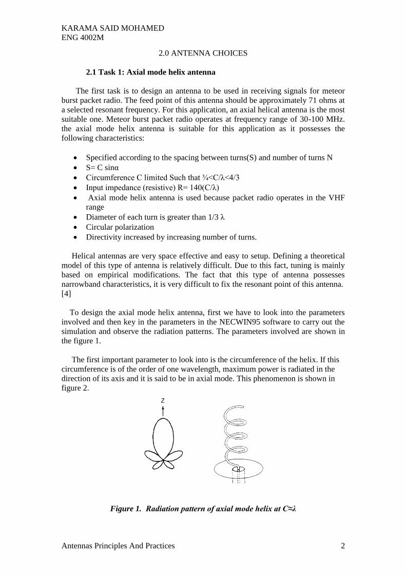
The first important parameter to look into is the circumference of the helix. If this
circumference is of the order of one wavelength, maximum power is radiated in the
direction of its axis and it is said to be in axial mode. This phenomenon is shown in
figure 2.
Figure 1. Radiation pattern of axial mode helix at C≈λ
KARAMA SAID MOHAMED
ENG 4002M
Antennas Principles And Practices 3
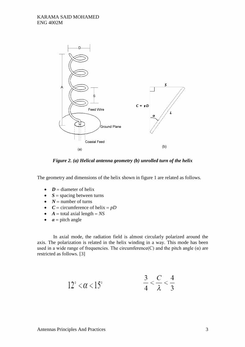
Figure 2. (a) Helical antenna geometry (b) unrolled turn of the helix
The geometry and dimensions of the helix shown in figure 1 are related as follows.
D diameter of helix
S spacing between turns
N number of turns
C circumference of helix pD
A total axial length NS
α pitch angle
In axial mode, the radiation field is almost circularly polarized around the
axis. The polarization is related in the helix winding in a way. This mode has been
used in a wide range of frequencies. The circumference(C) and the pitch angle (α) are
restricted as follows. [3]
KARAMA SAID MOHAMED
ENG 4002M
Antennas Principles And Practices 4
2.1.1 Parameter Calculations
For this task we only know the feed impedance which is 71 Ω and the operating
frequency of meteor burst radio is around 70 MHz. these two parameters are used to
calculate all the required dimensions and geometry for the helix antenna.
First we find the wavelength (λ).
λ=300/f (in MHz)
Having f=70MHz, then
λ= 300/70=4.28 m
The next parameter we find is the circumference;
Using the relationship: R= 140(C/ λ)
Having R=71 Ω and λ=4.28m then:
71=140(C/4.28), hence,
C=71(4.28) ÷ 140 = 2.17 m
But for an axial mode helix antenna, the circumference should practically be almost
one wavelength (λ). Therefore;
We take 0.95(λ),
0.98x4.28 = 4.19 m
Then we find the diameter
Having C= π D, Therefore:
D= C/ π,
D= 4.19/ π = 1.33 m
Now we find the spacing S between turns
Knowing that, C= √2S λ, we have C=4.19, λ=4.28, we can find S.
S=C2
/ 2 λ, hence,
S= (4.19)2/2(4.28) = 2.06 m
The wire length can be calculated as;
C*N, where n is the number of turns, therefore; wire length L=4.19*8=33.5 m

KARAMA SAID MOHAMED
ENG 4002M
Antennas Principles And Practices 5
Now we determine the feed length by using,
Feed length=N*ℓ Where,
ℓ=√ (C2 +S
2), hence,
ℓ=√ (2.172+2.06
2) =2.99 m, therefore
Feed length= 2.99*8(N) =23.9 m
2.2. Task 2: Yagi Uda antenna
This task requires the design of a high gain antenna that operates in the lowest of
the UHF amateur radio bands (430-440MHz). The feed point impedance should be 50
Ω, with a gain of 8 dBi and a front to back ratio of 15dB. The side lobe suppression
should be 15dB. The most suitable antenna for this application is the Yagi Uda as it
possesses the following characteristics. [1][2]
Linear polarization
High gain of 5 to 18dBi
Narrow bandwidth of 5 to 10%
It is non-dispersive
Has impedance Zin of 50 to 300 Ω
High efficiency of above 90%
Figure 3. Structure of a seven element Yagi Uda
As shown in figure 3, a yagi uda antenna is composed of three types of elements
(rods), the reflector, the driven dipole and the directors. These rods are connected by a longitudinal rod.

KARAMA SAID MOHAMED
ENG 4002M
Antennas Principles And Practices 6
The lengths of the rods in a Yagi uda are all in the range of about half
wavelength (1/2 λ) and the space between the elements is in range of about a third
wavelength (1/3 λ). The only rode that is connected directly to the feeder is the
driving element. The other elements’ main purpose is to couple to the transmitter
power through the locally available electromagnetic fields which induce the current.
A folded dipole is often used as the driving element. [3][1]
A folded dipoles standing alone will possess a driving impedance of around 300
ohms to the feeder. Due to the presence of the other elements, a shunting effect occurs
that will reduce the driving point impedance to the range of about 20-90 ohms. The
restriction of the maximum gain in a yagi uda antenna is defined by the gain of a
dipole and is about 1.66 times the number of elements used. The yagi uda takes the
form of a travelling wave structure and increasing the number of elements normally
improves the directivity, gain and front to back ration. However there is a trade-off
where increasing the number of elements increases the number of side lobes. [3]
2.2.1 Dimensions and Geometry Calculations.
For this task we are given the feed point impedance= 50ohms, gain of 8 dBi, front to
back ratio of 15Db and side lobe suppression of 15dB. This antenna is to operate in
the lowest of the UHF amateur radio, this is about 430 MHz. therefore,
λ=300/f (in MHz)
λ =300/430 = 0.69 m
As mentioned earlier, the length rods should be in the range of about 1/2 λ and the
space between the elements is in range of about 1/3 λ. Therefore the dimensions
should be approximately;
Rod length= 1/2*0.69= 0.345 m
Space between antennas= 1/3*0.69= 0.23 m
The total length of antenna=1.5 λ= 1.035 m
The height of antenna= 10 λ= 10*0.69= 6.9m
I will design a 7 element yagi uda with the range of dimensions values around
the ones calculated above. The table 2.2.1 below shows the antenna elements and the
dimensions. (Taking spacing of 0.17 m between elements which is about 0.25 λ
between the reflector and the driven element and 0.2m(0.29 λ) between directors.
Element Length in λ Length in m
Reflector 0.50 0.34
Driven 0.47 0.33
Director 1 0.43 0.30
Director 2 0.43 0.30
Director 3 0.42 0.29
Director 4 0.40 0.28
Director 5 0.39 0.27
Table 2.2.1 seven element yagi uda antenna dimensions
KARAMA SAID MOHAMED
ENG 4002M
Antennas Principles And Practices 7
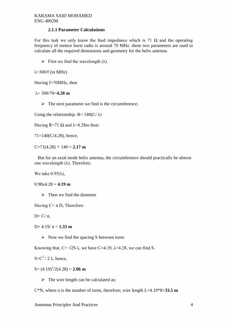
3.0 SIMULATION RESULTS
Using the NECWIN95 software for antenna design, the following results in form
of diagrams and plots were obtained.
3.1 Axial mode helical antenna.
Figure 3.1 (a) helix generator with calculated parameters
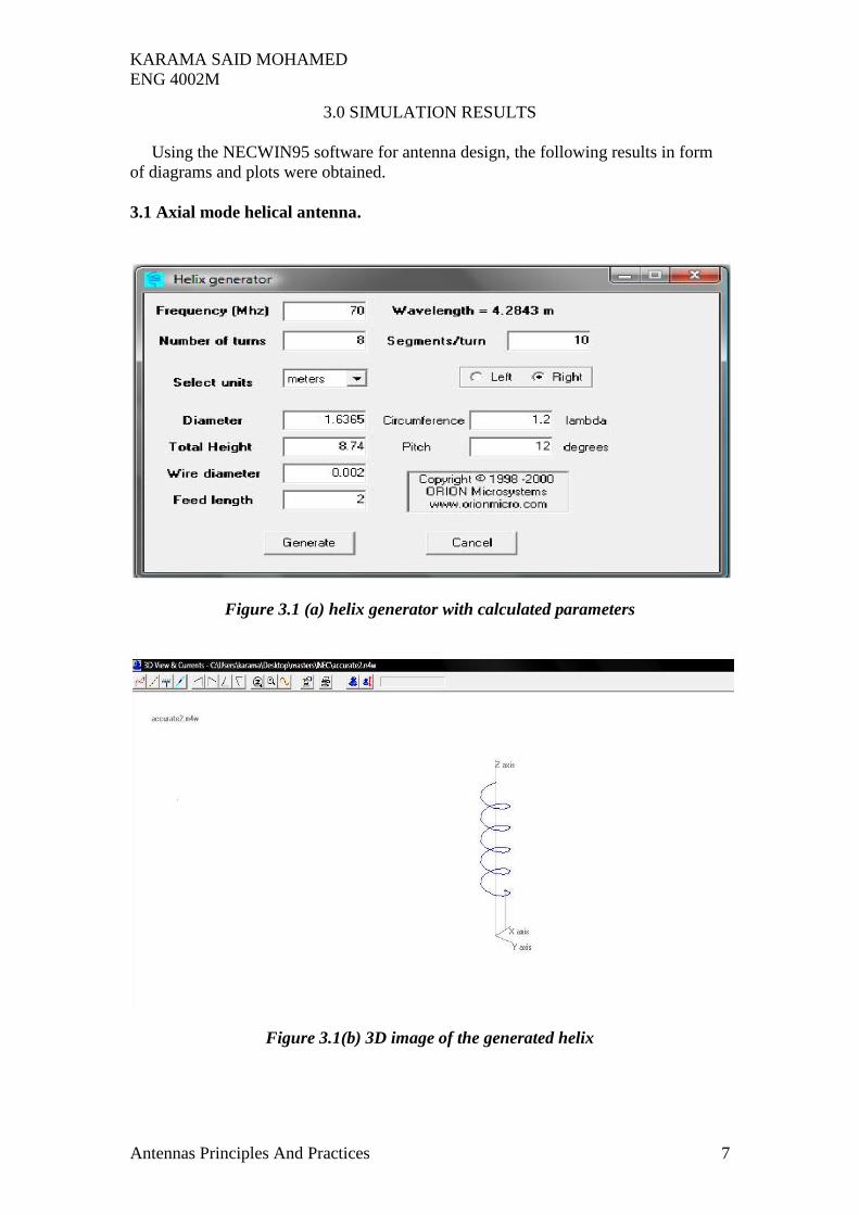
Figure 3.1(b) 3D image of the generated helix

KARAMA SAID MOHAMED
ENG 4002M
Antennas Principles And Practices 8
Figure 3.1(c) the generated helix’s current flow and pulses
Figure 3.1 (d) the helix antenna’s 3D radiation pattern
KARAMA SAID MOHAMED
ENG 4002M
Antennas Principles And Practices 9
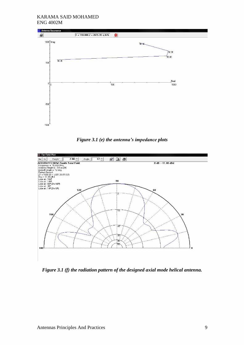
Figure 3.1 (e) the antenna’s impedance plots
Figure 3.1 (f) the radiation pattern of the designed axial mode helical antenna.
KARAMA SAID MOHAMED
ENG 4002M
Antennas Principles And Practices 10
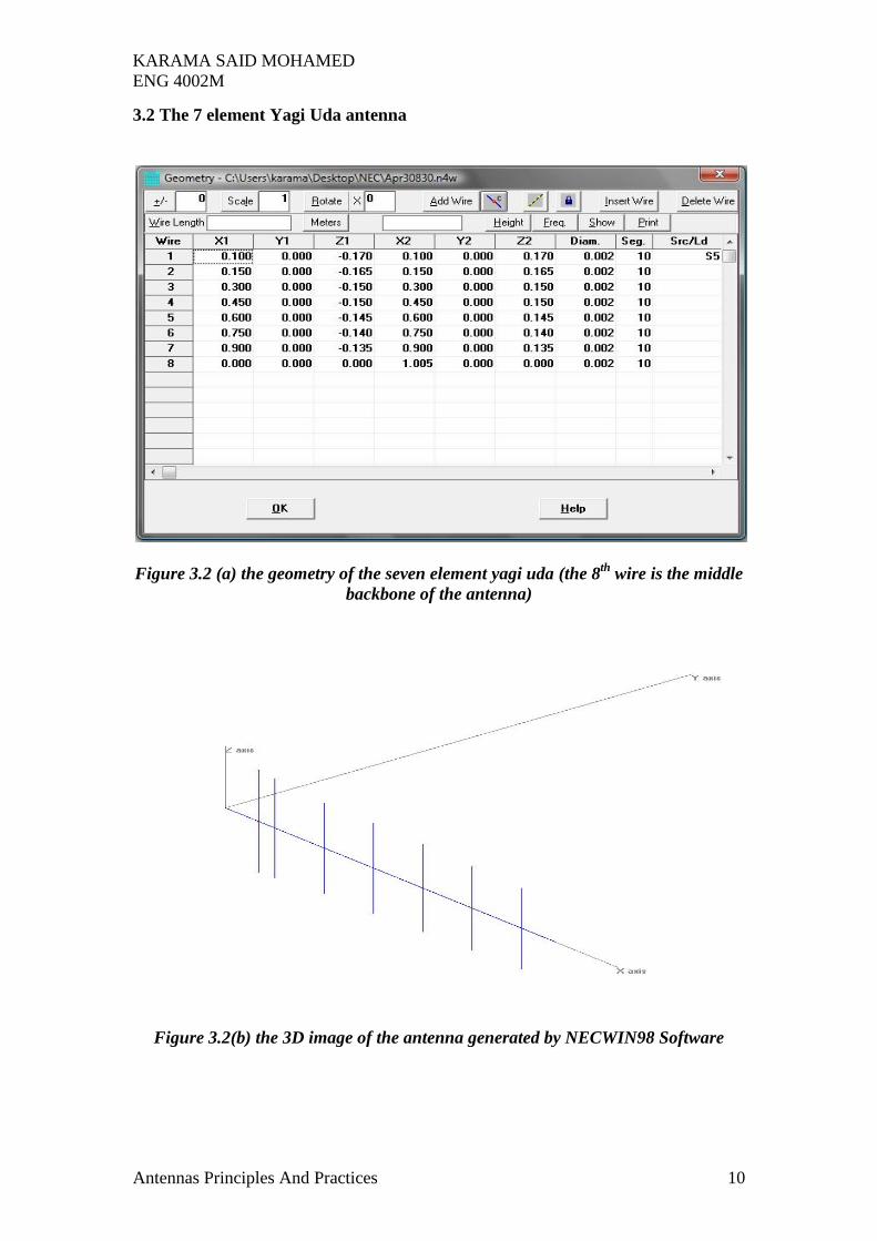
3.2 The 7 element Yagi Uda antenna
Figure 3.2 (a) the geometry of the seven element yagi uda (the 8th
wire is the middle
backbone of the antenna)
Figure 3.2(b) the 3D image of the antenna generated by NECWIN98 Software

KARAMA SAID MOHAMED
ENG 4002M
Antennas Principles And Practices 11
Figure 3.2(c) the pulses of the antenna and the pulse numbers
Figure 3.2(d) the 2D image of the seven segment yagi uda
KARAMA SAID MOHAMED
ENG 4002M
Antennas Principles And Practices 12
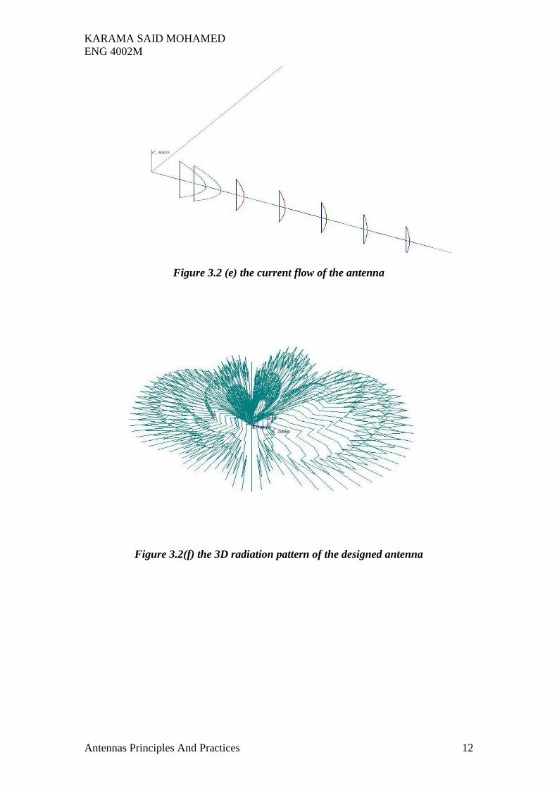
Figure 3.2 (e) the current flow of the antenna
Figure 3.2(f) the 3D radiation pattern of the designed antenna

KARAMA SAID MOHAMED
ENG 4002M
Antennas Principles And Practices 13
Figure 3.2 (g) the impedance plot of the designed Yagi Uda.
Figure 3.2(h) 2D radiation pattern at zenith

KARAMA SAID MOHAMED
ENG 4002M
Antennas Principles And Practices 14
Figure 3.2 (i) 2D radiation pattern at azimuth
3.2 (j) the optimizer interfaces (optimising the resonance)

KARAMA SAID MOHAMED
ENG 4002M
Antennas Principles And Practices 15
3.2 (j) the optimizer interfaces (optimising the front to back gain ratio)
Figure 3.2(k) geometry of antenna after optimisation

KARAMA SAID MOHAMED
ENG 4002M
Antennas Principles And Practices 16
4. CONCLUSION
In any communication system, the antenna is the most crucial component and if
the antenna does not perform well, the whole system is a failure. Antenna are
classified or grouped according to the way they function rather than the applications
they are used in.
In this experimental procedure of designing two antennas according to given
specifications, it is learnt that this designing process considers a lot of factors ranging
from the operating frequency to the input impedance and the gain of antennas.
In helix antennas it is observed that the number of turns plays a major role in
determining the directivity of the antenna. The spacing between the turns and the
pitch angle are also of considerable effect to the antennas performance. The helix
generator available in the NECWIN95 software simplifies the work of determining
the geometry of the antenna for the designer.
The antenna choice for the second task was the yagi uda because it is the most
appropriate to the given specification like high gain and frequency range of UHF. The
number of directors and how they are spaced from each other affects the performance
of this kind of antenna. It is observed that the parameters of this antenna are entirely
dependant on the wavelength (λ). The length of the elements and the distance between
the reflector and the driven element are also of considerable effect on the antenna
performance.
To obtain an optimum antenna performance, there must be a trade-off between
certain characteristics like number of side lobes and the number of element in the
antenna. More elements might increase the gain but at the same time increase he
number of side lobes which in most cases is undesired. To achieve the best optimal
antenna performance, the parameters must be well balance to get the best of each
desired characteristics without losing another one. Antenna optimization can be done
easily using computer programmes like NECWIN95.

KARAMA SAID MOHAMED
ENG 4002M
Antennas Principles And Practices 17
References:
[1] John D. Kraus and Ronald J.Marhefka, Antennas for All Applications, third
edition, McGraw Hill, 2002.
[2] Constantine A.Balanis Antenna Theory, Analyis and Design, second edition, John
Wiley and Sons, 1997.
[3] Yagi uda antennas, available at:
http://personal.ee.surrey.ac.uk/Personal/D.Jefferies/yagiuda.html (accessed February
2008)
[4] ‘Application note 1, V/UHF Antenna Design, available at:
http://www.numatechnologies.com/pdf/an_antenna.pdf (Accessed march 2008)