Marine Antenna Installations - NMEA antenna installations ibex... · Antenna Basics VHF, SSB,...
35
IBEX 2011 Speakers: David Gratton- Martek-Palm Beach, FL Johnny Lindstrom- Westport Shipyard, WA Marine Antenna Installations Property of the NMEA. Shall not be copied or re-distributed.
Transcript of Marine Antenna Installations - NMEA antenna installations ibex... · Antenna Basics VHF, SSB,...

IBEX 2011
Speakers:
David Gratton- Martek-Palm Beach, FLJohnny Lindstrom- Westport Shipyard, WA
Marine Antenna Installations
Property of the NMEA. Shall not be copied or re-distributed.

Seminar Overview
• Antennas– AIS, Cellular, Radar, Satellite, SSB, VHF, WX
• Location – Aesthetic vs. Practical vs. Customer Requests
• Testing• Installations

Antenna BasicsVHF, SSB, AM/FM, AIS, Cellular
• Any Conducting Material Will Work as an Antenna on Any Frequency
• Only Reason for Specific Antennas Is to Control Radiation Pattern (n/a for SSB on most vessels)
– Total Radiated Power Is Same
• Focused Radiation Pattern Results in Antenna “Gain” (n/a for SSB on most vessels)
• Example: Spot light vs. Flood light (n/a for SSB)
Property of the NMEA. Shall not be copied or re-distributed.
Antenna LocationsVHF, SSB, AM/FM, AIS, Cellular
• Objectives:• Preserve Antenna Aperture• Avoid Co- and Cross-channel Interference• Avoid Shadowing Potential Services• Avoid Damage from High-power Transmitters• It is not possible to locate all antennas in
optimum locations. Most all installations are a compromise.
Property of the NMEA. Shall not be copied or re-distributed.
• GPS, Satellite & Cell Antennas must be outside Radar Beam
• GPS Antennas below SATCOM Antenna Beam
• Cell Transmissions Can Interfere with GPS Reception
• Multiple Radar Antennas at Different Heights (18”)
• Sat TV Spacing Dependent on Radar Output Power
Antenna SpacingImportant Notes
Property of the NMEA. Shall not be copied or re-distributed.
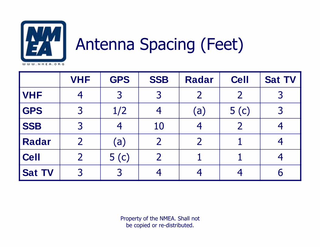
Antenna Spacing (Feet)
VHF GPS SSB Radar Cell Sat TVVHF 4 3 3 2 2 3
GPS 3 1/2 4 (a) 5 (c) 3
SSB 3 4 10 4 2 4
Radar 2 (a) 2 2 1 4
Cell 2 5 (c) 2 1 1 4
Sat TV 3 3 4 4 4 6
Property of the NMEA. Shall not be copied or re-distributed.

Antenna Types
Application Description T or R Type
VHF Communication T/R Dipole
Sideband (SSB) Communication T/R MarconiAM/FM Entertainment R DipoleAIS Vessel Tracking R DipoleCellular Communication T/R DipoleGPS Navigation R Micro stripSatellite Comm. Communication T/R ParabolicSatellite TV Entertainment R Parabolic
Radar Collision Avoidance T/R ReflectorWeather Environment R Micro strip

Antenna Locations

Antenna Locations
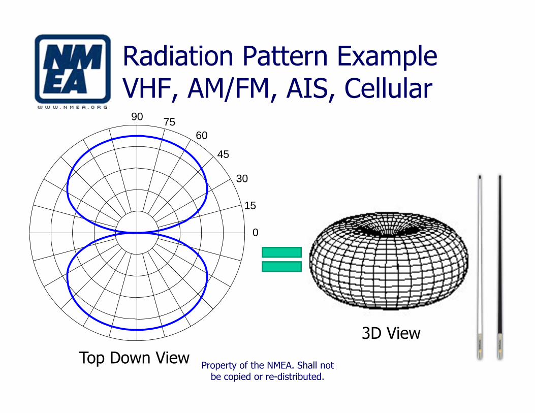
Radiation Pattern ExampleVHF, AM/FM, AIS, Cellular
90
30
45
6075
15
0
3D ViewTop Down View Property of the NMEA. Shall not
be copied or re-distributed.

High & Low Gain Patterns
Low Gain
High Gain

Antenna GainVHF, AM/FM, AIS, Cellular
• Measures the Ability to Focus Existing RF Energy (spot light vs. flood light)
• Measure Is in dB, a Ratio of– Maximum Radiated Power to the Radiated Power
of an Isotropic Source (dBi)– Maximum Radiated Power to the Radiated Power
of a ½ Wavelength Dipole (dBd)
Property of the NMEA. Shall not be copied or re-distributed.

Aperture DisturbancesVHF, SSB, AM/FM, AIS, Cellular
• Aperture Size Is a Function of Wavelength– VHF @ 156.800 MHz, Dipole Aperture ≈ 1.6 Feet– Applications at 1+ GHz, Dipole Aperture << 1 Foot
• Antennas with Dipole Apertures– VHF, AIS,Cell Phone, AM/FM, DGPS
• Conductors within Aperture Change Antenna Characteristics
Property of the NMEA. Shall not be copied or re-distributed.

Antennas- VHF & SSB
• Physical Support– Withstand 10 Lbs. Force 24” from the Mounting– How do we measure?– Two-point Mount for Antennas Longer Than 8’
• Arrangement– Maximize Spacing to Minimize Interference
• Safety– SSB Shock Hazard due to high voltage– Radar Radiation Hazard
Property of the NMEA. Shall not be copied or re-distributed.

VHF Test Parameters
Test Measurement Nominal Value Tolerance
1 RF Forward Power 25 Watts ≥ 20 Watts
2 RF Reflected Power at DUT Output
0 Watt ≤ 3 Watts
3 Voltage at DUT Input
13.6 Volts ≥ 12 Volts
DUT= Device Under Test
Property of the NMEA. Shall not be copied or re-distributed.
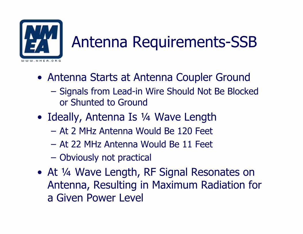
Antenna Requirements-SSB
• Antenna Starts at Antenna Coupler Ground– Signals from Lead-in Wire Should Not Be Blocked
or Shunted to Ground
• Ideally, Antenna Is ¼ Wave Length– At 2 MHz Antenna Would Be 120 Feet– At 22 MHz Antenna Would Be 11 Feet– Obviously not practical
• At ¼ Wave Length, RF Signal Resonates on Antenna, Resulting in Maximum Radiation for a Given Power Level

SSB Installation
• Ground System Complexity– Hull Material: Metal Hulls Are an Excellent Antenna
Counterpoise– Salt Water Is More Conductive Than Fresh Water– Much more “effective area” is required in fresh water
• Ground Conductors– Surface Area Is Important– RF travels on surface, not conductor– Copper Straps and Copper Tubes (hydraulic tubing)
Have Greater Surface Area for a Given WeightProperty of the NMEA. Shall not
be copied or re-distributed.
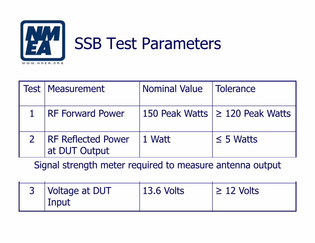
SSB Test Parameters
Test Measurement Nominal Value Tolerance
1 RF Forward Power 150 Peak Watts ≥ 120 Peak Watts
2 RF Reflected Power at DUT Output
1 Watt ≤ 5 Watts
3
3 Voltage at DUT Input
13.6 Volts ≥ 12 Volts
Signal strength meter required to measure antenna output

Radar Location
• Beam Is Above Crew Spaces• No Obstructions on Critical Azimuth Bearings• Power density?
Radar Transmits a Focused Energy Beam That Can Be a Hazard to Humans and Other Receiving Equipment

Radar Mounting
• Consider Weight of Unit vs. Strength of Location– Many Fiberglass Arches Won’t Support Open Array
Radar Units without Reinforcement• Optimum Attitude Level with Horizon When
Cruising– Powerboats: 2° Down at Rest or Horizontal ± 2°
at Cruise– Sailboats: Horizontal ± 2°
• Vertical Height Within 30’ of Water Level to Avoid Missing Close in Targets (discuss)
Property of the NMEA. Shall not be copied or re-distributed.

Radar Connections
• Cable between Display and Array Unit Performs Multiple Functions– Longer Lengths Are Available from Manufacturer– Best practice is to use Manufacturer Approved
Extension Cables when required, instead of splicing
• Use Shielded Power and Communications Cables• Ground Units to RF ground bus to Reduce EMI
Property of the NMEA. Shall not be copied or re-distributed.

Wind & Weather Sensors
• Must be installed in 360° “Clean Air”– This assures wind & temperature readings will be accurate.– Check alignment placement (differs with manufacturers).
• Mast installations:– Mount at top (power or sail).
• Hardtop installations:– Mount at least 1 ft. above, and 3’ back from front of hardtop.
• Radar Arch installations:– Mount at least 1 ft. above arch.
Property of the NMEA. Shall not be copied or re-distributed.

Wind & Weather Sensors:Dead Air Zone

Satellite Constellation Geometry• Geostationary – Always in Same
Relative Position in Sky.TV, Communications, Weather22,000 miles
• Non-stationary – Cross from Horizon to Horizon while in use.Height varies with purpose.
• Low Earth Orbit (LEO)400-1200 miles
• Medium Earth Orbit (MEO)12,000 miles (GPS)
• Some Systems Must Maintain a Minimum of 2-3 Satellites in View at All Times

Satellite System Antenna Types
• Wide Variety of Marine Communication Needs• Receive Only
– GPS, Weather, TV, Other Entertainment
• Transmit/Receive– Voice/Fax– Internet Data Services– Video Conferencing
• Motion Compensated Systems
Property of the NMEA. Shall not be copied or re-distributed.

GPS Antenna Installations
• Must have a clear view of the sky
• Must be outside Radar Beam, either above or below
• Should be below SATCOM Antenna Beam
• Cell Transmissions Can Interfere with GPS Reception
Property of the NMEA. Shall not be copied or re-distributed.

Typical Satellite System
Above Deck
Below Deck
Interface is dependent on Satellite Dome & System

Satellite Dome Location
• Physically Secure Location• Communications are Line-of-sight
– Clear View of as Much Sky as Practical
• Follow Antenna Spacing Requirements• Outside Any Radar Array by 6 Feet
Property of the NMEA. Shall not be copied or re-distributed.

Multi-path Interference
• Paths Arrive at Different Times• Received Signal is Summation of
All Signals Received
DirectEcho 1Echo 2Signal
Property of the NMEA. Shall not be copied or re-distributed.

Orientation and Location
Antenna UnitAntenna Unit
O X
°15Antenna UnitAntenna Unit °15Antenna UnitAntenna Unit
O X
Flat Surface
No Obstacles
Property of the NMEA. Shall not be copied or re-distributed.

Effect of Misalignment
• Misalignment Moves Predicted Satellite Position– 30 Second Normal Search Time– 2 to 5 Minute Search Time when Misaligned– Systems with both position & heading inputs are typically
faster
45 °
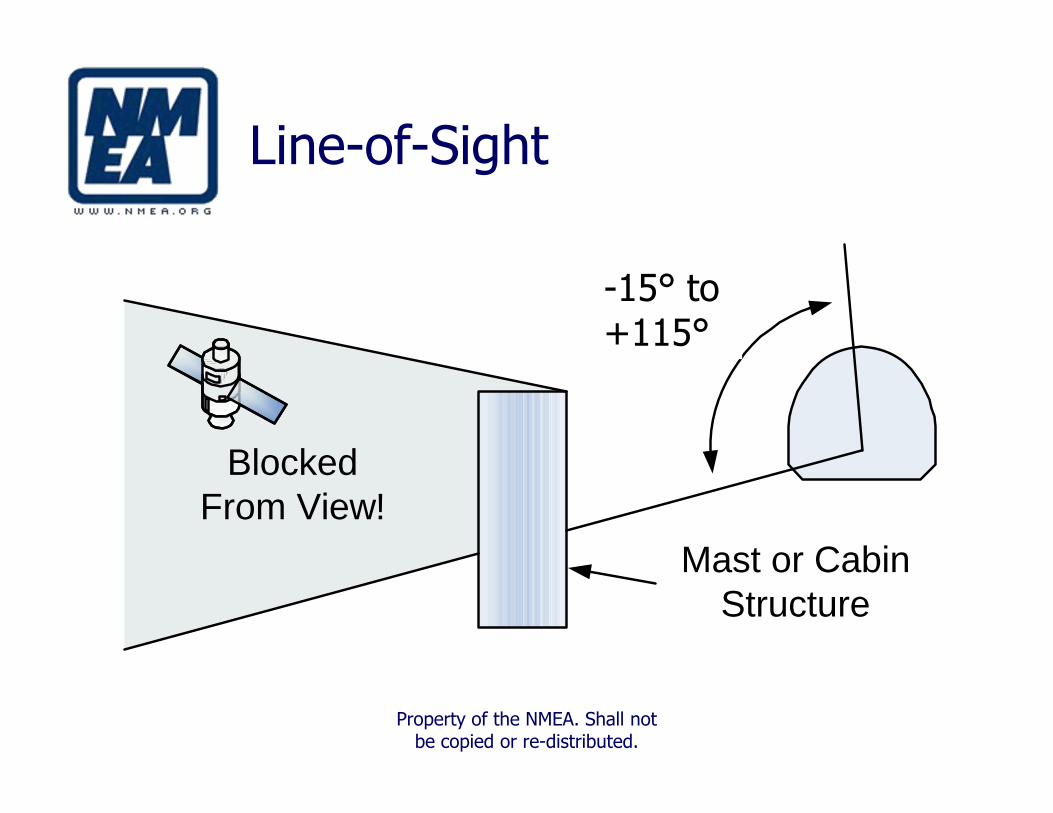
Line-of-Sight
-15° to+85°
BlockedFrom View!
Mast or CabinStructure
-15° to +115°
Property of the NMEA. Shall not be copied or re-distributed.

Satellite DomeRadar Clearance
±15°
• Average Radar Antenna has a vertical beamwidth of ±20°
±10°

System Grounding
• 10 AWG or larger Ground wire
• Connect dome and Control Unit to RF Ground
• Run wire to Local RF Ground Bus
Property of the NMEA. Shall not be copied or re-distributed.

Summary
• Antenna characteristics are determined by physical construction
• Practical Considerations Drive Mounting Locations
• Mounting options vary from vessel to vessel• Poor location can affect antenna performance
Property of the NMEA. Shall not be copied or re-distributed.