Annual Report of the Association EURATOM/CEA 2000
33
Annual Report of the Association EURATOM/CEA 2000 Compiled by : Ph. MAGAUD and F. Le VAGUERES ASSOCIATION CEA/EURATOM DSM/DRFC CEA/CADARACHE 13108 Saint-Paul-Lez-Durance (France)
Transcript of Annual Report of the Association EURATOM/CEA 2000

Annual Report of the Association EURATOM/CEA
2000
Compiled by : Ph. MAGAUD and F. Le VAGUERES
ASSOCIATION CEA/EURATOM DSM/DRFC
CEA/CADARACHE 13108 Saint-Paul-Lez-Durance (France)
- I -
CONTENTS
INTRODUCTION ................................................................................................................................. 1
EFDA TECHNOLOGY PROGRAMME ........................................................................ 3
Physics Integration
Diagnostics TW0-DIAG-DEV ITER diagnostic window development ........................................................................ 5
Heating and Current Drive TW0-ICRF/ANT ICRF Antenna and vacuum transmission line development - ICRH Antenna coupling: Near field computations....................................................... 7 CEFDA 00-519 Neutral beam heating design for EDA extension ......................................................... 11 TW0-NB.DEV.1 Neutral beam development for EDA extension - EU-JA collaborative experiment on KAMABOKO source.......................................... 15 TW0-NB.DEV.3 Neutral beam development for EDA extension - 1 MeV SINGAP accelerator ......................................................................................... 19 TW0-NB.DEV.4 Neutral beam development for EDA extension - Manufacture and testing of a prototype 1 MeV bushing for SINGAP ......................... 23
Vessel/In Vessel
Plasma Facing Components CEFDA 99-501 Critical heat flux and thermal fatigue testing of CFC monoblocks - 200 kW electron beam gun test .................................................................................... 27 CNET 98-480 Thermal fatigue testing of divertor full scale prototype - 200 kW electron beam gun test .................................................................................... 29 CNET 98-485 Thermal fatigue testing of baffle full scale prototype - 200 kW electron beam gun test .................................................................................... 35 DV4.3 Optimisation and manufacture of HHF components - Study of flat tile cascade failure possibility for high heat flux components ................. 37 TW0-DV4/01 Optimisation of manufacture of HHF components ...................................................... 41 TW0-DV4/02 Optimisation of Cu-SS-Tube Joints.............................................................................. 43 TW0-T438-01 Development and testing of time resolved erosion detecting techniques ..................... 45

- II -
Vessel/Mechanical structure T216-GB8 Small scale testing of FW/BS modules ........................................................................ 49 TW0-LASER/CUT VV intersector maintenance - Further development of high power Nd YAG - Improvement of YAG laser back-plate cutting using powder injection ....................... 51 TW0-LASER/HYD YAG laser process for cutting and welding of the hydraulic module blanket - CW YAG laser process for cutting and welding of the hydraulic connections ............ 53 TW0-LASER/REWELD VV intersector maintenance - Further development of high power Nd YAG - Laser rewelding after cutting........................................................................................ 55 TW0-LASER/WELD VV intersector joining - Further development of high power Nd YAG - Laser welding with multipass filler wire ...................................................................... 59 TW0-T301/01 Ultrasonic inspection for vessel inter-sector weld - Completion of ultrasonic inspection process development - Optimisation of the ultrasonic inspection method : effect of the wave polarity and frequency on the signal to noise ratio .................................................................... 61 TW0-T420/06 Fabrication of a first wall panel with HIP’ed beryllium armor .................................... 65 TW0-T420/08 Development of HIP fabrication technique - Faisability of using HIP for the manufacturing of Primary First Wall Panel (PFWP) ........................................ 69 TW0-T427/03 Development and characterization of one-step SS/SS and CuCrZr/SS HIP joints including mock-up fabrication............................................................................ 73 TW0-T508/04 Development of Be/CuCrZr HIPping technique .......................................................... 75 TW0-T508/05 Development of Be/CuCrZr brazing techniques .......................................................... 77 TW0-T519/01 Low temperature water radiolysis ................................................................................ 79 V63 Detailed investigation of CuAl25 (IG1) - Its joints with 316LN stainless steel and joints testing procedure.......................................................................................... 81
Assembly & Maintenance T252 Radiation tolerance assessment of standard components for remote handling and process instrumentation .......................................................................... 85 T329-5 In vessel RH dexterous operations - Task extension 2 ................................................. 91 TW0-DTP/1.1 Carrier and bore tools for 4" bend pipes....................................................................... 95 T329-4 TW0-DTP/1.2 Prototypical manipulator for access through IVVS...................................................... 99 TW0-DTP/1.4
Magnet Structure CEFDA 00-517 Design of cryogenic transfer lines and ring manifolds for ITER-FEAT ...................... 103 CEFDA 00-541 PF correction coils : conceptual design and analysis, CS cooling inlets, conductor analysis tools ............................................................................................... 105 M40 Design work on magnet R&D ...................................................................................... 109
- III -
M50 Conductor R&D - Development of NbTi conductors for ITER PF coils ..................... 111 TW0-T400-1 CSMC and TFMC installation and test ........................................................................ 113
Tritium Breeding and Materials
Breeding Blanket Water Cooled Lithium Lead (WCLL) Blanket TTBA-1.1 TBM Adaptation to Next Step...................................................................................... 117 TTBA-2.1 Blanket Manufacturing Techniques - Definition of specifications for demonstrators ............................................................. 121 TTBA-2.2 Blanket Manufacturing Techniques - Solid HIP demonstrator for fabrication and coating, fabrication of double wall tubes ................................................................................... 125 TTBA-2.4 Blanket Manufacturing Techniques - Feasibility of powder HIP fabrication for TBM or TBM components ......................... 129 TTBA-2.5 Blanket Manufacturing Techniques - Double-wall tube out-of-pile testing (DIADEMO experimental program) .................. 133 TTBA-3.1 Coating qualification and irradiation tests - Permeation barrier qualification - Fabrication and characterization of CVD specimens ................................................... 137 TTBA-3.5 Coating qualification and irradiation tests - Permeation out-of-pile testing ................. 141 WPA4.2.3 TTBA-4.1 Processes and components - Tritium extraction from Pb-17Li .................................... 143 TTBA-5.3 Safety and Licensing - Modelling of the lithium/lead water interaction ...................... 147 TTBA-5.4 Safety and Licensing - Development of minor components & instrumentation........... 149 TTBA-6.2 MHD Effects - Test and modeling of natural convection MHD .................................. 153 Helium Cooled Pebble Bed (HCPB) Blanket TTBB-2.3 Blanket Manufacturing Techniques - First wall manufacturing by HIP forming technique .................................................... 157 TTBB-5.D3 Development of ceramic breeder pebble beds - Characterization of Li2TiO3 pebble beds...................................................................... 159 TTBB-5.D4 Development of ceramic breeder pebble beds - Validation of Li2TiO3 fabrication with pre-industrial means of the lab fabrication steps - Mastering/Optimizing ..................................................... 163
Structural Materials development Advanced materials TTMA-1.2 SiC/SiC ceramic composites - SiC/SiC composite development and characterization................................................. 167 TTMA-1.4 SiC/SiC ceramic composites - Compatibility of SiC/SiC composite with liquid Pb-17Li alloy................................... 169

- IV -
TTMA-1.6 SiC/SiC ceramic composites - Brazing of SiC/SiC composites with thermo-mechanical testing................................. 173 Reduced Activation Ferritic Martensitic (RAFM) Steels SM-2-3-1 Mechanical properties of F82H weldments .................................................................. 177 SM-3-3 Corrosion in water conditions - Corrosion water with additives .................................. 181 SM-3-5.1 Compatibility with hydrogen and liquid - SCC behaviour of Eurofer in aqueous environments ................................................... 185 SM-4-3 F82H weldability with filler metal ............................................................................... 187 SM-5-7 Small size specimen technology................................................................................... 191 SM-6-1 Development of high dose high temperature - Low temperature, high dose irradiation test with ISTC................................................ 193 TTMS-1.1 RAFM steels - Irradiation performance - Neutron irradiation of RAFM steels to 30-35 dpa at 325°C......................................... 197 TTMS-2.1 RAFM steels - Metallurgical and mechanical characterization - SM-2-1 Metallurgical characterization of EUROFER 97 steel ................................................. 199 TTMS-2.2 RAFM steels - Metallurgical and mechanical characterization - Mechanical characterization of Eurofer 97 : tensile and impact properties.................. 203 TTMS-2.3.1 RAFM steels - Metallurgical and mechanical characterization - Mechanical properties of diffusion bonded welds (RAFM/RAFM HIP joint) ............. 207 TTMS-2.3.2 RAFM steels - Metallurgical and mechanical characterization - Mechanical properties of weldments ............................................................................ 211 TTMS-2.4 RAFM steels - Metallurgical and mechanical characterization - Mechanical properties of powder HIP Eurofer............................................................. 215 TTMS-4.1 RAFM steels - Qualification fabrication processes - Eurofer powder HIP development and characterization............................................... 217 TTMS-4.2 RAFM steels - Qualification fabrication processes - Mechanical alloying including ODS ............................................................................ 221 TTMS-4.3 RAFM steels - Qualification fabrication processes - RAFM weldability..................... 225 TTMS-4.4 RAFM steels - Qualification fabrication processes - Dissimilar welding RAFM/316LN............................................................................... 229 TTMS-4.5 RAFM steels - Qualification fabrication processes - Solid HIP process and qualification ............................................................................. 231 TTMS-5.1 RAFM steels - Rules for design and inspection - Design code assessment and development ................................................................... 235 TTMS-5.4 RAFM steels - Rules for design and inspection - Data collection and data base maintenance .................................................................. 239 TTMS-6.3.1 RAFM steels - Qualification of high performance steels - Development of RAFM-ODS steels............................................................................. 243 Neutron Source TTMI-001 IFMIF - Accelerator facility ......................................................................................... 245

- V -
Safety and Environment CEFDA 00-539 French contribution to ITER licensing working group................................................. 249 SEA1-14 Assist JCT on safety documentation ............................................................................ 251 SEA4-4 Plant safety assessment - ITER-FEAT design CAT V accident analysis : H2 production via delayed plasma shutdown................................................ 253 SEA5-2 Validation of computer codes and models - ISAS maintenance................................... 255 SEA5-3 Validation of computer codes and models - Thermohydraulical code validate experiments ............................................................. 257 TSW-2.1 Waste and Decommissioning Strategy - Detritiation of structural material and management of tritiated waste.......................... 259 TSW-2.6 Waste and Decommissioning Strategy - Development and assessment of overall strategies....................................................... 263 TW0-SEA3.5 Hydrogen deflagration/detonation analysis .................................................................. 265 TW0-SEA4 Plant safety assessment................................................................................................. 267
System Studies
Power Plant Conceptual Studies (PPCS) TW0-TRP-1.1 Safety and environmental requirements ....................................................................... 271 TW0-TRP-2.4 Economic and operational requirements ...................................................................... 273 TW0-TRP-2.5 Supply requirements..................................................................................................... 277 TW0-TRP-3D4 Reactor integration ....................................................................................................... 279 TW0-TRP-4D5 High heat flux components........................................................................................... 283 TW0-TRP-4D7 Economics and operational analyses - Maintenance schemes...................................... 285
Socio-Economics Studies SERF2 Externalities of fusion - Accident external costs and sensitivity analysis on the site location............................ 289
UNDERLYING TECHNOLOGY PROGRAMME ................................................ 293
Vessel/In Vessel
Plasma Facing Components UT-PFC&C-HFW Transparent polycrystalline ceramics ........................................................................... 295 UT-PFC&C-HIP Mechanical behaviour of HIP joints ............................................................................. 299

- VI -
UT-PFC&C-SiC C-SiC and boron doped graphite .................................................................................. 303 UT-PFC&C-SiC/MJ Development of SiC/metal joining technology ............................................................ 307 UT-SM&C-VVI Design and analysis of vacuum vessel and internals .................................................... 309
Vessel/ Mechanical Structure UT-SM&C-BIM Dissimilar diffusion-bonded joints mechanical testing ................................................ 313
Assembly and Maintenance UT-RH1 Remote Handling Techniques - Technology and control for remote handling systems.................................................. 317 UT-RH2 Remote Handling Techniques - Graphical programming for remote handling ............................................................... 319 UT-RH3 Remote Handling Techniques - Advanced technologies for high performances actuators ............................................. 323 UT-RH4 Remote Handling Techniques - Radiation tolerance assessment of electronic components from specific industrial technologies for remote handling and process instrumentation.................... 327
Tritium Breeding and Materials
Breeding Blanket UT-SM&C-BLK Development of breeding blankets ............................................................................... 333 UT-SM&C-COAT Development of an oxide layer on Fe-Al coatings ....................................................... 337 UT-SM&C-LM/DC Diffusion coefficient measurements in liquid metals ................................................... 341 UT-SM&C-LM/MAG Liquid metal corrosion under magnetic field................................................................ 345 UT-SM&C-LM/Refrac Compatibility of refractory materials with liquid alloys .............................................. 349 UT-SM&C-LM/WET Wetting of materials by liquid metals........................................................................... 353
Materials Development Structural Materials UT-SM&C-LAM/Mic Influence of the martensite morphology on the plasticity behaviour of the Eurofer steel ....................................................................................................... 357 UT-SM&C-LAM/Weld Laser weldability of LAM steels (Eurofer97) .............................................................. 361 UT-SM&C-LAM2 Irradiated behaviour of Reduced Activation (RA) martensitic steels after neutron irradiation at 325°C................................................................................. 363 UT-SM&C-LAM3 Microstructural investigation of Reduced Activation Ferritic-Martensitic (RAFM) steels by Small Angle Neutron Scattering (SANS) ....................................... 367 UT-SM&C-ODS Development of forming and joining technologies for ODS steels .............................. 371

- VII -
Nuclear Data UT-N-NDA Nuclear data assessment ............................................................................................... 375
Fuel Cycle UT-T1 Separation of the D/T mixture from helium in fusion reactors using superpermeable membranes - Development of superpermeable membranes suitable to operate under ion bombardment .............................................. 379
Safety and Environment UT-S-BLK Blanket Safety .............................................................................................................. 383 UT-S-MITIG Evaluation and mitigation of the risk connected with air or water ingress................... 385
System Studies UT-SM&C-REL Reliability modeling & assessment .............................................................................. 389 UT-SM&C-TDC Innovative Thermo-Dynamic Cycles studies (TDC) .................................................... 393 UT-SM&C-TMNC Thermal-hydraulic models for nuclear components ..................................................... 397
INERTIAL CONFINEMENT FUSION PROGRAMME .............................. 399
ICF01 Intense laser and particle beams dynamics for ICF applications .................................. 401 ICF02 Civil applications of inertial confinement fusion - Cryogenic targets production using magnetic levitation .............................................. 405 ICF03 Laser-matter interaction at relativistic intensities and fast igniter studies .................... 411 ICF-KiT-PRC Overview on power reactor concepts ........................................................................... 415
APPENDIX 1 : Directions contribution to the fusion programme ........................ 419
APPENDIX 2 : Allocations of tasks .......................................................................................... 423
APPENDIX 3 : Reports and publications .............................................................................. 429
APPENDIX 4 : CEA tasks in alphabetical order .............................................................. 441
APPENDIX 5 : CEA sites ................................................................................................................. 445
- 5 - EFDA technology / Physics Integration / Diagnostics
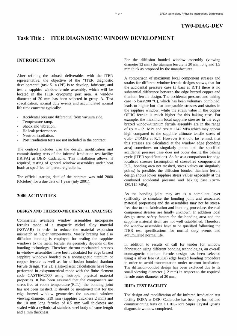
TW0-DIAG-DEV Task Title : ITER DIAGNOSTIC WINDOW DEVELOPMENT INTRODUCTION After refining the subtask deliverables with the ITER representative, the objective of the “ITER diagnostic development” (task 5.1a (PE) is to develop, fabricate, and test a sapphire window-ferrule assembly, which will be located in the ITER cryopump port area. A window diameter of 20 mm has been selected in group A. Test specification, normal duty events and accumulated normal life time concerns typically: - Accidental pressure differential from vacuum side. - Temperature ramp. - Shock and vibration. - He leak performance. - Neutron irradiation. - Post irradiation tests are not included in the contract. The contract includes also the design, modification and commissioning tests of the infrared irradiation test-facility (IRIFA) at DER- Cadarache. This installation allows, if required, testing of general window assemblies under heat loads at specified temperature gradients. The official starting date of the contract was mid 2000 (October) for a due date of 1 year (july 2001). 2000 ACTIVITIES DESIGN AND THERMO-MECHANICAL ANALYSES Commercial available window assemblies incorporate ferrules made of a magnetic nickel alloy material (KOVAR) in order to reduce the material expansion mismatch at higher temperatures. Mostly brazing but also diffusion bonding is employed for sealing the sapphire windows to the metal ferrule; its geometry depends of the bonding technology. Therefore thermo-mechanical stresses in window assemblies have been calculated for edge brazed sapphire windows bonded to a nonmagnetic titanium or copper ferrule as well as for diffusion bonded titanium ferrule design. The 2D elasto-plastic calculations have been performed in axisymmetrical mode with the finite element code CASTEM2000 using isotropic physical material properties. It has been assumed that the components are stress-free at room temperature (R.T.); the bonding joint has not been meshed. It should be mentioned that for the edge brazed window geometries the assumed window viewing diameter is19 mm (sapphire thickness 2 mm) and the 10 mm long ferrules of 0.5 mm wall thickness are sealed with a cylindrical stainless steel body of same length and 1 mm thickness.
For the diffusion bonded window assembly (viewing diameter 12 mm) the titanium ferrule is 20 mm long and 1.5 mm thick as proposed by the manufacturer. A comparison of maximum local component stresses and strains for different window-ferrule designs shows, that for the accidental pressure case (5 bars at R.T.) there is no substantial difference between the edge brazed copper and titanium ferrule design. The accidental pressure and baking case (5 bars/200 °C), which has been voluntary combined, leads to higher but also comparable stresses and strains in the sapphire window, while the strain value in the copper OFHC ferrule is much higher for this baking case. For example, the maximum local sapphire stresses in the edge brazed window/titanium ferrule assembly are in the range of τrz = –121 MPa and σzz = +242 MPa which may appear high compared to the sapphire ultimate tensile stress of σult= 240MPa at R.T. However it should be remind, that this stresses are calculated at the window edge (bonding area) sometimes on singularly points and the specified accidental pressure case does not occur during the baking cycle (ITER specification). As far as a comparison for edge localised stresses (assumption of stress-free component at R.T., bonding area not meshed, stress values on singularly points) is possible, the diffusion bonded titanium ferrule design shows lower sapphire stress values especially at the combined accidental pressure and baking case (σrr=-139/114 MPa). As the bonding joint may act as a compliant layer (difficulty to simulate the bonding joint and associated material properties) and the assemblies may not be stress-free due to the fabrication and bonding procedure, the real component stresses are finally unknown. In addition local design stress safety factors for the bonding area and the sapphire material itself are not well established. Therefore the window assemblies have to be qualified following the ITER test specifications for normal duty events and accumulated normal life. In addition to results of call for tender for window fabrication using different bonding technologies, an overall nonmagnetic titanium ferrule design has been selected using a silver free (AuCu) edge brazed bonding procedure in order to avoid transmutation under neutron irradiation. The diffusion-bonded design has been excluded due to its small viewing diameter (12 mm) in respect to the required ferrule outer diameter of 20 mm. IRIFA TEST FACILITY The design and modification of the infrared irradiation test facility IRIFA at DER- Cadarache has been performed and commissioning tests on a CIEL-Tore Supra Crystal Quartz diagnostic window completed.

- 6 - EFDA technology / Physics Integration / Diagnostics
In this installation an electrical graphite heater allows a continuous or cycled heat flux deposition (0- 50 W/cm²) on window surfaces under vacuum, which have however to be provided with a large band absorbent layer. Therefore general window assemblies can be tested, if required, under well-defined temperature gradients (e.g. windows of group C) and it permits to validate the calculation code. CONCLUSIONS Thermal and thermo-mechanical analyses have been performed under specified temperature and pressure loads for different sapphire window-ferrule assemblies. In addition to results of call for tender for window fabrication, an overall nonmagnetic titanium ferrule design has been selected using a silver free edge brazed bonding procedure in order to avoid transmutation under neutron irradiation. Fabrication of 5 sapphire window- ferrule assemblies (instead of 3 required) has started and ITER required tests will follow until July 2001. The design and modification of the infrared irradiation test facility IRIFA at DER- Cadarache has been performed and commissioning tests on a CIEL-Tore Supra Crystal Quartz diagnostic window completed. The failure (crack) which appeared on the tested crystal quartz window assembly during the first slow cool down cycle confirms, that thermo-mechanical analysis alone are not sufficient and so thermal tests are mandatory in order to qualify such assemblies.
TASK LEADER Manfred LIPA DRFC/SIPP CEA Cadarache 13108 St Paul Lez Durance Cedex Tél. : 33 4 42 25 46 58 Fax : 33 4 42 25 49 90 E-mail : [email protected]

- 7 - EFDA technology / Physics Integration / Heating and Current Drive
TW0-ICRF/ANT Task Title : ICRF ANTENNA AND VACUUM TRANSMISSION LINE
DEVELOPMENT ICRH Antenna coupling: Near field computations INTRODUCTION This work is devoted to the modelling of ICRH ITER antenna. The model description should be realistic as possible while taking also into account the computation time for finding the current distribution in the antenna structure. The first step of this study is to look for a compromise between the exactness of the model description and the above computation time. We have received the plan of the antenna structure with the quotations at the end of September. An adequate modelling of this antenna can not carry out without simplifications. At first, we have searched the ways in which the number of the current elements can be reduced. The modelling starts with the construction of a mesh that brings out a higher order of symmetries. These symmetries lead to the reduction of the number of the coupling coefficients computed. The assumptions made on the current distribution in different parts of the antenna have been then tested. During this work, a numerical problem has appeared and the expensive computation time for each run has hindered to solve it. We have also developed tools in order to draw the electric field maps (3D vector field plots or contours). The first part of the progress report deals with ITER antenna modelling. The rules used in the building up of the antenna model is then described and finally the first results obtained on the near field computations are presented.
2000 ACTIVITIES PART ONE : ITER ANTENNA MODELLING The plan (in fig 1) shows the complex feature of the antenna structure. The currents are distributed in each part of the antenna such that these distributions can be computed self-consistently. We have tested the physical exactness of such current distributions. In the first step, the procedure seeks whether or not to apply the magnetic shielding to the different parts of the antenna. The mesh size for the different components of the antenna structure is then chosen and the intersections between differently oriented planes are determined so as to ensure the continuity of the current distribution. a) On the choice of the current basis : First, the ITER antenna is embedded in a box surrounding the straps. This situation can be correctly described by considering all the current components on the surface of the surrounding box. This is the same situation as in the cases of the septa. The magnetic shielding should be considered in all parts so as to isolate one part of the antenna from other parts.
Figure 1 : a) View of the ITER antenna from the plasma and b) modelling

- 8 - EFDA technology / Physics Integration / Heating and Current Drive
We have shown that thick screen blades can change the radiated power and the shape of the k-spectrum [1]. But another important parameter is the difference in distance between the inner blade surface-plasma and the outer blade surface-plasma. Then, for the given ITER parameters, the effects of the thick screen blades are small enough such that they can be assimilated to thin screen blades. This approximation leads to an underestimation of the radiated power but on the other hand, the computation is accelerated as the number of elements used to describe the Faraday screen (20 blades) is reduced by factor of 8. The strap is treated as a thin tape without magnetic shielding. The assumption of the unidirectional current is well-justified in the previous works [2-3]. However, one can query the thick strap choice, which remains an open question. The thin strap approximation is also imposed because, if thick straps are considered, the number of current elements associated with the 16 straps is multiplied by 8 leading to unrealistic computation times. b) On the optimisation of the computation time : The reduction of the computation time is absolutely necessary to test a large number of cases. The mesh size results from a compromise between the required accuracy and the computation time. The need to follow the dimensions of the antenna structure destroys generally the possibility of building a mesh with a high level of symmetries and consequently leads to very high computation times. Under these conditions, the only way to reduce the computation time is to limit as possible the number of the current elements on each component of the antenna structure while satisfying the required accuracy.This method is advantageous as the size of the current element gets larger and, in the Fourier space, the k-spectrum becomes smaller. The components of the coupling matrix are thus quickly computed. However, the k-boundaries are fixed by the smallest element built to describe the antenna structure. We have tested various configurations of the strap and thus deduced that around 10 elements are required to obtain a good current profile on the strap. For the screen blades, the current can change its profile on a strap width. The lowest value of the number of current elements is 16 and the dimension found on the ITER antenna plan fixes the width of the grid. The septa are described otherwise. Here, we have preferred to extend the symmetries by using the surrounding box. The main reason for this choice is related to the geometrical constraints and to the full current description of these elements. That is the reason why the basic mesh element corresponds to a square for the septa and boxes. The model of the ITER antenna structure has more than 1500 current elements. The effective number of computed coupling matrix components is only 400000/2250000 matrix coefficients.
This computation requires approximately 1 Go of RAM and one week of computation time. A new computer with enough memory has been bought to speed up the computations. PART TWO : FIRST RESULTS a) Vacuum : The beginning of the work is devoted to convince us that our choices are justified. The main part of the tests has been made in vacuum at the frequency ν = 50 MHz or 55 Mhz (isotropic medium). On the figure 2a, the current intensities associated to each element of the mesh are shown. From this result, it is easy to see that the determination of the mesh is important. Asymmetries on the septum can be observed and depend on the relative position of a septum element from the straps. However, the integrated value of the current in front of a strap does not depend on the positions of elements connected to the strap. We have verified that the current distribution agrees with the expected one. In the case presented on the figure 2b, the z-component of the electric field corresponds to a normalised radiated power to 1 MW. Here one can see the important role of the Jx current distribution on the E// generation. b) Plasma : The ITER-FEAT plasma parameters are used to compute the electric field (magnetic field Bo = 5 T, plasma density no
= 1 1020 m-3 and frequency ν = 55 MHz). The computations show the significant role of the septa to reduce the parallel component of the electric field. However the z-component is significant at the edge of the box and can create asymmetric RF sheaths at the corners of the antenna. This kind of asymmetries has been seen at lower level in the cases of Q1 antenna Tore Supra simulations (α =7°) and permits to explain the asymmetry in the hot spots distribution by using a model of the convective cells [4]. In these simulations, the radiated power or resistance is in good agreement with the experimental data and shows the good dependencies. The computed resistance for the ITER antenna without screen is ~ 12 W/A per strap. The introduction of a tilted Faraday screen (α =16°) brakes the symmetries in the current distribution and the electromagnetic fields. However, the computed values seem to be too asymmetric in z direction. We have begun to test this configuration to know the reason why we have asymmetry in z-direction. At this time, we have not found something wrong in the code and we have planned to test configurations with smaller values of the tilted angle to understand if there is a physical explanation to this effect. An other possible way to solve this problem is to modify the description of the Faraday screen by connecting each blade to the septa surrounding each strap but that increases too munch the number of the needed elements, the required memory goes thus beyond the computer memory. The code has to be modified to reduce the size and the number of the arrays but that reduces the possibilities of the code to compute several quantities at the same time.

- 9 - EFDA technology / Physics Integration / Heating and Current Drive
00.10.20.3X
- 1
- 0.5
0
0.5
1
Y
- 0.5 0 0.5
Z00.10.20.3
X
- 0.5 0 0.5
Z
−0.
0
0.z
−1
−0.5
0
0. 5
1
y
−200000−100000
0100000
200000
Im E
− 5
0.5z
Figure 2 : a) View of the current distribution on the sixteen straps with a septum b) Parallel electric field (V/m) at x=3 cm in front of the antenna on a grid 51x51
The data file of the electric field components (imaginary and real parts) takes on the disk around 500 Ko per plane with a grid 51x51. The space step is ~4 cm in this case and can become lower. With our k-boundaries the space resolution is around 1.5 cm. To have more space accuracy, the k-range has to be increased, however more memory is required (if it is possible) and the computation takes more time. REFERENCES [1] S. Pécoul, S. Heuraux, R. Koch*, G. Leclert, M.
Bécoulet and L. Colas, "ICANT code: a tool to compute the characteristics of ICRH antennae with realistic structures and their near fields" EPS 2000 27th EPS Conf. controlled fusion and plasma physics 12-16 June 2000 Budapest.
S. Pecoul, Heuraux S, Koch R Leclert G, A Bécoulet
and L. Colas, "Self-consistent computations of electric field near ICRH antennae: Application to the Tore Supra antenna", 13th Topical Conference on applications of Radio frequency Power in plasmas, Annapolis, AIP Conf. Proc. 485, 361 (1999).
[2] S. Pécoul, S. Heuraux, R. Koch and G. Leclert, "On
the computation of the self-consistent currents on ICRH antenna taking into account magnetic shielding", 2nd Euro-physics Top Conf on RF Heating and Current drive of fusion devices Brussels January 20-23 1998 Vol 22A 45 (1998).
[3] S. Pécoul, S. Heuraux, R. Koch and G. Leclert, "Self-
consistent currents on ICRH antenna and screen parts taking into account magnetic shielding", Praha June
29-July 3 1998 ICPP and 25th EPS Conf. controlled fusion and plasma physics, 22C, 1402 (1998).
[4] L. Colas, M. Bécoulet, L. Costanzo, S. Pécoul, S. Heuraux, S. Brémond, C. Desgranges, A. Bécoulet, Ph. Ghendrih, "Heat Load Patterns on Tore Supra ICRH Antennas", EPS 2000 27th EPS Conf. controlled fusion and plasma physics 12-16 June 2000 Budapest.
TASK LEADER Stéphane HEURAUX S. PECOUL LPMIA Faculté des Sciences UHP Boîte Postale 239 54506 Vandoeuvre Cedex Tél. : 33 3 83 91 25 72 Fax : 33 3 83 27 34 98 E-mail : [email protected]

- 10 - EFDA technology / Physics Integration / Heating and Current Drive
- 11 - EFDA technology / Physics Integration / Heating and Current Drive
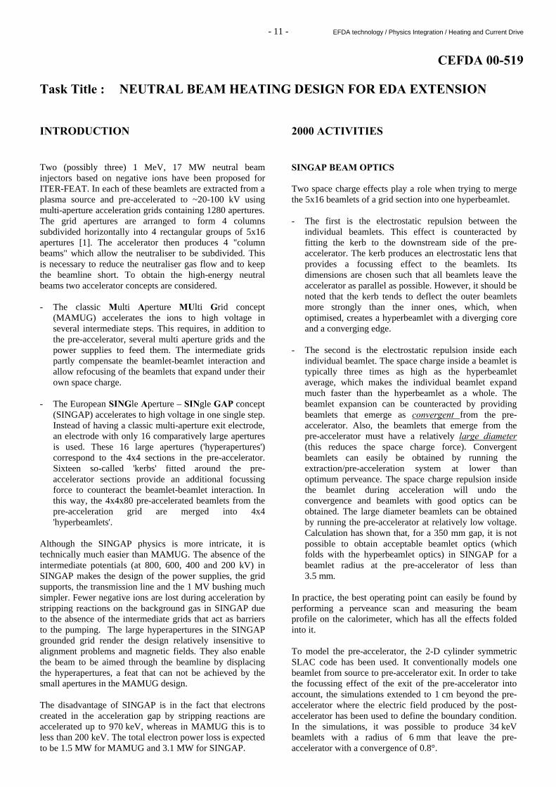
CEFDA 00-519 Task Title : NEUTRAL BEAM HEATING DESIGN FOR EDA EXTENSION INTRODUCTION Two (possibly three) 1 MeV, 17 MW neutral beam injectors based on negative ions have been proposed for ITER-FEAT. In each of these beamlets are extracted from a plasma source and pre-accelerated to ~20-100 kV using multi-aperture acceleration grids containing 1280 apertures. The grid apertures are arranged to form 4 columns subdivided horizontally into 4 rectangular groups of 5x16 apertures [1]. The accelerator then produces 4 "column beams" which allow the neutraliser to be subdivided. This is necessary to reduce the neutraliser gas flow and to keep the beamline short. To obtain the high-energy neutral beams two accelerator concepts are considered. - The classic Multi Aperture MUlti Grid concept
(MAMUG) accelerates the ions to high voltage in several intermediate steps. This requires, in addition to the pre-accelerator, several multi aperture grids and the power supplies to feed them. The intermediate grids partly compensate the beamlet-beamlet interaction and allow refocusing of the beamlets that expand under their own space charge.
- The European SINGle Aperture – SINgle GAP concept
(SINGAP) accelerates to high voltage in one single step. Instead of having a classic multi-aperture exit electrode, an electrode with only 16 comparatively large apertures is used. These 16 large apertures ('hyperapertures') correspond to the 4x4 sections in the pre-accelerator. Sixteen so-called 'kerbs' fitted around the pre-accelerator sections provide an additional focussing force to counteract the beamlet-beamlet interaction. In this way, the 4x4x80 pre-accelerated beamlets from the pre-acceleration grid are merged into 4x4 'hyperbeamlets'.
Although the SINGAP physics is more intricate, it is technically much easier than MAMUG. The absence of the intermediate potentials (at 800, 600, 400 and 200 kV) in SINGAP makes the design of the power supplies, the grid supports, the transmission line and the 1 MV bushing much simpler. Fewer negative ions are lost during acceleration by stripping reactions on the background gas in SINGAP due to the absence of the intermediate grids that act as barriers to the pumping. The large hyperapertures in the SINGAP grounded grid render the design relatively insensitive to alignment problems and magnetic fields. They also enable the beam to be aimed through the beamline by displacing the hyperapertures, a feat that can not be achieved by the small apertures in the MAMUG design. The disadvantage of SINGAP is in the fact that electrons created in the acceleration gap by stripping reactions are accelerated up to 970 keV, whereas in MAMUG this is to less than 200 keV. The total electron power loss is expected to be 1.5 MW for MAMUG and 3.1 MW for SINGAP.
2000 ACTIVITIES SINGAP BEAM OPTICS Two space charge effects play a role when trying to merge the 5x16 beamlets of a grid section into one hyperbeamlet. - The first is the electrostatic repulsion between the
individual beamlets. This effect is counteracted by fitting the kerb to the downstream side of the pre-accelerator. The kerb produces an electrostatic lens that provides a focussing effect to the beamlets. Its dimensions are chosen such that all beamlets leave the accelerator as parallel as possible. However, it should be noted that the kerb tends to deflect the outer beamlets more strongly than the inner ones, which, when optimised, creates a hyperbeamlet with a diverging core and a converging edge.
- The second is the electrostatic repulsion inside each
individual beamlet. The space charge inside a beamlet is typically three times as high as the hyperbeamlet average, which makes the individual beamlet expand much faster than the hyperbeamlet as a whole. The beamlet expansion can be counteracted by providing beamlets that emerge as convergent from the pre-accelerator. Also, the beamlets that emerge from the pre-accelerator must have a relatively large diameter (this reduces the space charge force). Convergent beamlets can easily be obtained by running the extraction/pre-acceleration system at lower than optimum perveance. The space charge repulsion inside the beamlet during acceleration will undo the convergence and beamlets with good optics can be obtained. The large diameter beamlets can be obtained by running the pre-accelerator at relatively low voltage. Calculation has shown that, for a 350 mm gap, it is not possible to obtain acceptable beamlet optics (which folds with the hyperbeamlet optics) in SINGAP for a beamlet radius at the pre-accelerator of less than 3.5 mm.
In practice, the best operating point can easily be found by performing a perveance scan and measuring the beam profile on the calorimeter, which has all the effects folded into it. To model the pre-accelerator, the 2-D cylinder symmetric SLAC code has been used. It conventionally models one beamlet from source to pre-accelerator exit. In order to take the focussing effect of the exit of the pre-accelerator into account, the simulations extended to 1 cm beyond the pre-accelerator where the electric field produced by the post-accelerator has been used to define the boundary condition. In the simulations, it was possible to produce 34 keV beamlets with a radius of 6 mm that leave the pre-accelerator with a convergence of 0.8°.
- 12 - EFDA technology / Physics Integration / Heating and Current Drive
The SINGAP starting condition is determined by the ITER type segmented pre-accelerator. Thus one has to start with a 5x16 array of pre-accelerated beamlets, spaced 20 mm apart. Beamlet energy (34 keV), radius (6 mm) and convergence angle (0.8o) are as found for the pre-accelerator mentioned above. Due to symmetry it is sufficient to model a 1/4 section of the problem. The modelling was done with the space charge module SCALA from the 3D VectorFields electromagnetic software suite OPERA-3D. Computing limitations meant that the typical size of a finite element cell in the simulation could not be reduced to less than 2x2x10 mm. The ITER beamline features a neutraliser that extents to 4.6 m beyond the accelerator exit. The reason why very parallel charged particle beams that are metres long can exist at all, is in the space charge neutralisation in regions where the electric field is zero. Ionisation of background gas particles by the beam produces ions that neutralise the space charge of the beam. Because the exit apertures of the SINGAP exit grid are very wide, the electric field from the accelerator penetrates beyond the exit grid and it is not clear where exactly the space charge neutralisation starts. Typically, one expects of the order of the aperture width. This modelling uncertainty can only be resolved by experimentation. Pending such an experiment, it has been assumed that space charge neutralisation starts at a distance L beyond the exit grid given by: 1/L2=1/Lx
2+1/Ly2, where Lx and Ly represent the
horizontal and the vertical width of the SINGAP aperture. For a multi-aperture exit grid, L is negligible due to the small size of the apertures.
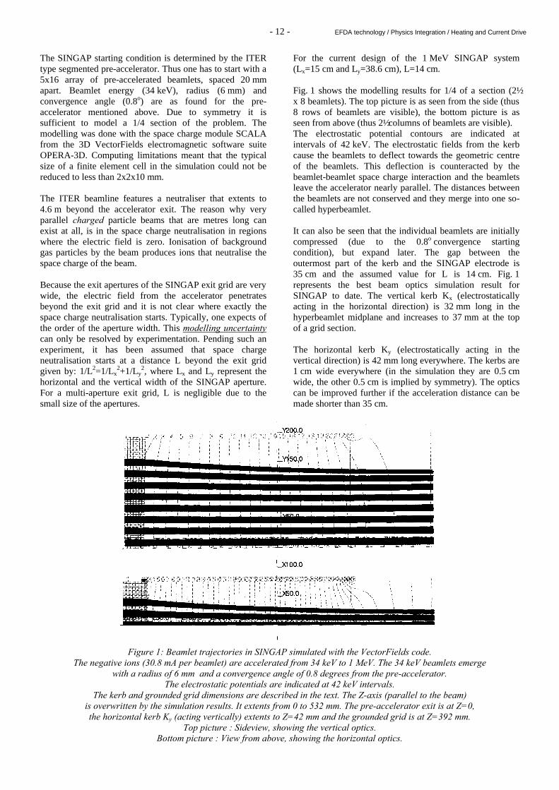
For the current design of the 1 MeV SINGAP system (Lx=15 cm and Ly=38.6 cm), L=14 cm. Fig. 1 shows the modelling results for 1/4 of a section (2½ x 8 beamlets). The top picture is as seen from the side (thus 8 rows of beamlets are visible), the bottom picture is as seen from above (thus 2½ columns of beamlets are visible). The electrostatic potential contours are indicated at intervals of 42 keV. The electrostatic fields from the kerb cause the beamlets to deflect towards the geometric centre of the beamlets. This deflection is counteracted by the beamlet-beamlet space charge interaction and the beamlets leave the accelerator nearly parallel. The distances between the beamlets are not conserved and they merge into one so-called hyperbeamlet. It can also be seen that the individual beamlets are initially compressed (due to the 0.8o convergence starting condition), but expand later. The gap between the outermost part of the kerb and the SINGAP electrode is 35 cm and the assumed value for L is 14 cm. Fig. 1 represents the best beam optics simulation result for SINGAP to date. The vertical kerb Kx (electrostatically acting in the horizontal direction) is 32 mm long in the hyperbeamlet midplane and increases to 37 mm at the top of a grid section. The horizontal kerb Ky (electrostatically acting in the vertical direction) is 42 mm long everywhere. The kerbs are 1 cm wide everywhere (in the simulation they are 0.5 cm wide, the other 0.5 cm is implied by symmetry). The optics can be improved further if the acceleration distance can be made shorter than 35 cm.
Figure 1: Beamlet trajectories in SINGAP simulated with the VectorFields code. The negative ions (30.8 mA per beamlet) are accelerated from 34 keV to 1 MeV. The 34 keV beamlets emerge
with a radius of 6 mm and a convergence angle of 0.8 degrees from the pre-accelerator. The electrostatic potentials are indicated at 42 keV intervals.
The kerb and grounded grid dimensions are described in the text. The Z-axis (parallel to the beam) is overwritten by the simulation results. It extents from 0 to 532 mm. The pre-accelerator exit is at Z=0, the horizontal kerb Ky (acting vertically) extents to Z=42 mm and the grounded grid is at Z=392 mm.
Top picture : Sideview, showing the vertical optics. Bottom picture : View from above, showing the horizontal optics.

- 13 - EFDA technology / Physics Integration / Heating and Current Drive
Figure 2 : Emittance diagrams θ=V⊥/Vz for the trajectories shown in Fig. 1. The core of the hyperbeamlet is expanding, whereas the edge of the hyperbeamlet is converging.
On the left : Vertical emittance diagram: θy=Vy/Vz. On the right : Horizontal emittance diagram: θx=Vx/Vz.
The acceptance angle for passing the ITER Residual Ion Dump (RID) is indicated. Fig. 2 shows the emittance diagram obtained for the 34 keV pre-accelerated beams described above. The emittance diagram in Fig. 2 shows the good optics obtained. The limiting angles formed by the segmented RID in particular are indicated. The individual beamlets that make up the hyperbeamlet can still be identified. It can be seen that the outer parts of the hyperbeamlet tend to move inwards. This is a general feature of SINGAP systems equipped with a kerb. It obviously helps to increase the beam transmission of such systems, although it might lead to localised areas of high power density inside the beamline which require attention in the design of ion dumps and the calorimeter. The transmission through the neutraliser and RID has been calculated using a code that models the beam as the sum of the individual beamlets. Each beamlet is modelled as a Gaussian with a starting position, starting angle and divergence as results from the VectorFields calculations. A random number between 0 and 1 mrad is added to the divergence of each beamlet. A random number between -1 and +1 mrad is added to the starting angle of each beamlet. This is done to make the results more 'realistic'. For the SINGAP beam optics case presented here, the transmission is 96.7%. Because a code calculation is always idealised in some way (think of source uniformity, ion temperature, magnetic field deflections, grid distortions, etc.), the calculations have been repeated with a divergence 2 mrad greater than calculated. For MAMUG, which has a calculated divergence of 3 mrad, the calculation was performed with 5 mrad beamlets that are steered to overlap at the exit of the RID. For SINGAP, the calculated divergences were increased by 2 mrad and the angles from the emittance diagram have been used. The resulting beamlet divergences are also of the order of 5 mrad. The calculated transmission is: - for MAMUG : 88.9 % - for SINGAP : 86.4 % Using identical assumptions, SINGAP has a beam transmission that is 2.5% less than MAMUG.
It should be noted, however, that the power from a SINGAP accelerator could be larger than for a MAMUG accelerator due to fewer grid losses (which is its "raison d'être"). BEAM STEERING Experiments and an analytical expression based on thin lens electrostatic theory have been presented by [2]. Their expression can be used to calculate the hyperbeamlet steering produced by a possible aperture offset displacement of the SINGAP grounded grid. Because the hyperapertures in this grid are so large, a significant displacement can be afforded without affecting the beam quality. Their analytical expression yields a steering of -0.7 mrad/mm for a beam being accelerated to 1 MeV over a 35 cm gap width. It should be noted that the analytical expression refers to circular apertures, whereas the SINGAP hyperapertures are rectangular. Simulations have been performed using the 3-D VectorFields code. Symmetry can not be used any longer and consequently the finite element grid had to be quite crude, not much smaller than the beamlet radius. Although the exact solution obtained is rather crude, the calculated steering is likely to be correct because fine beamlet detail is not relevant for the steering (it is for the beam optics). The steering results are: - Horizontal : -1.0 mrad/mm - Vertical : -0.65 mrad/mm where the circular formula gave -0.7 mrad/mm. Horizontally, the hyperbeamlets must crossover at the plasma boundary at 23.4 ms from the grounded grid. Vertically they must crossover at the tangency point 29.9 m from the grounded grid. In MAMUG it is not possible to displace the small apertures sufficiently without hitting the grid(s) and therefore each grid has to be inclined in two dimensions, each of the grids is different.
- 14 - EFDA technology / Physics Integration / Heating and Current Drive
In SINGAP the large hyperapertures can be displaced significantly. The required steering and offsets are: - Horizontal : Middle columns : 80 mm/23.4 m = 3.4 mrad → 3.4 mm Outer columns : 240 mm/23.4 m = 10.3 mrad → 0.3 mm - Vertical : Middle rows : 198 mm/29.9 m = 6.6 mrad → 10.2 mm Outer rows : 594 mm/29.9 m = 19.9 mrad → 30.5 mm A crude simulation of a 30 mm offset in the vertical direction did not degrade the beam quality significantly. Therefore, using straight grids are an economic possibility in SINGAP. A simulation with a 60 mm displacement did degrade the beam quality. In any case, tolerances in the vertical direction are quite good. EXPERIMENTS Experiments in a SINGAP geometry have been carried out by J. Bucalossi et al. [3,4]. They compared experimental data from the Cadarache SINGAP experiment with model calculations (VectorFields OPERA-3D). The beam-optics calculations did indeed predict (and precede!) the experimental results. Although his experiments provide an excellent confirmation of the effect of all the electrostatic lenses in a SINGAP system, this can not be regarded as a full validation of the SINGAP concept because space charge effects on the beam optics were negligible due to the low beam current density of ~2 mA/cm2. Two computational runs with and without space charge effects included would result in profiles that are indistinguishable within the experimental resolution. Hence, further experimentation is necessary. REFERENCES [1] T. Inoue et al., Design of Neutral Beam System for
ITER-FEAT, Fusion Technology, SOFT conference (Madrid 2000).
[2] Y. Okumura, Y Mizutani and Y. Ohara, Experimental
study of ion beamlet steering by aperture displacement in two-stage accelerator, Rev. Sci. Instrum. 51(1980)471.
[3] J. Bucalossi, Etude de l'accélération électrostatique de
faisceaux d'ions négatifs H-/D- de haute puissance. Application à l'accélérateur SINGAP de 1 MeV, Thesis of the Paris University 5-11-1997.
[4] J. Bucalossi, C. Desgranges, M. Fumelli, P.
Massmann, A. Simonin: Beam optics of the SINGAP 1 MeV 100mA D- direct current accelerator for thermonuclear fusion, Review of Scientific Instruments, vol.70, n°4 (1999) p.1991-1993.
TASK LEADER P. MASSMANN DSM/DRFC/SCCP/GIDN CEA Cadarache 13108 St Paul Lez Durance Cedex Tél. : 33 4 42 25 62 74 Fax : 33 4 42 25 62 33 E-mail : [email protected]

- 15 - EFDA technology / Physics Integration / Heating and Current Drive
TW0-NB.DEV.1 Task Title : NEUTRAL BEAM DEVELOPMENT FOR EDA EXTENSION EU-JA collaborative experiment on KAMABOKO source INTRODUCTION The R&D task description states the objectives of this task as:
i. To demonstrate the high performance H-/D- ion production for long pulses, using the plasma grids developed for long pulse.
ii. To aim at higher current density (~300 A/m2), at lower source filling pressure (~0.1 Pa).
iii. To develop long life cathodes for stable, reliable operation, and less frequent maintenance.
The difficulties encountered in obtaining reliable long pulse operation and the expected current densities at the anticipated power levels have meant that essentially all the work so far has been directed at objective i. At the end of 1998 MANTIS successfully tested the first long pulse grid (the “frame cooled grid”, provided by JAERI) and achieved the required level of performance in H- at the expected parameters of arc power, grid temperature etc. As the frame cooled grid support had been damaged in transport from Japan, the second long pulse grid (the “actively cooled” grid, also from JAERI was installed shortly thereafter. The high arc efficiency achieved with the frame cooled grid was found for relatively few pulses and it is not yet reproduced with the actively cooled grid. After several months of investigations the reason for the reduced arc efficiency is still undetermined. Current investigations are concentrating on the effect of the change in grid material and the strength of the magnetic filter. 2000 ACTIVITIES The essential preparatory work and system modifications have been carried out for the long pulse operation, either at the expected parameters or with an arc power 50% above that initially foreseen. Several diagnostics have been put in place which should allow a better understanding of the negative ion production to be reached. They are a laser cavity ringdown system to measure the negative ion density a few millimetres in front of the plasma grid, a beam scanner to measure the beam profile (hence the accelerated H-/D- uniformity) immediately downstream of the accelerator, and the scanning Langmuir probe has been refurbished with updated software.
- Long pulses at the foreseen arc discharge power (≈50 kW) and filling pressure (0.3 Pa) can be regularly obtained.
- Extraction and acceleration for 1000 s has been
demonstrated in hydrogen operation, although at <280 A/m2.
- D- extraction for pulses of 10 s throughout a 1000 s
discharge has been demonstrated. - The plasma grid temperature is at, or close to, the
"optimum" operating temperature, 250 – 300°C at the anticipated required power levels.
- The D- current density is <100 A/m2. LONG PULSE D- OPERATION Obtaining long pulse D- operation has required substantial work on the KAMABOKO III source, the MANTIS test bed and its associated power supplies and data acquisition system. Arc series resistances : The 1 Ω air cooled resistance in series with each of the 12 filaments, have been replaced with 0.3 Ω water cooled resistances (coiled stainless steel tube embedded in epoxy). Source cooling water : The water cooling of the source and filaments has been increased. Source flanges : Uncooled diagnostic flanges on the ion source have been removed/replaced. HV protection system : The protection systems has been improved to increase reliability. Protection is now provided by a simple series resistances in each HV circuit, which normally ensures that breakdowns self extinguish. This is backed up by computer surveillance of the HV currents: if a threshold value is exceeded for >20 ms, the computer commands the system off. Extraction grid supports and feedthroughs : The grid 2 support has been completely rebuilt so that it is supported from grid 3 and the HV and water cooling come through a ceramic feedthrough located on the vacuum tank, which is capable of withstanding more than the acceleration voltage. Remote operation : As MANTIS is not a shielded test bed, the radiation dose to the operators from the neutron production during deuterium operation limits the total D- beam on time, and remote operation of the test bed is required for the foreseen long pulse operation. The system developed allows operation from a distant PC.

- 16 - EFDA technology / Physics Integration / Heating and Current Drive
0 . 0
0 . 2
0 . 4
0 . 6
0 . 8
1 . 0
1 . 2
1 . 4
1 . 6
2 0 6 0 1 0 0 1 4 0 1 8 0 2 2 0 2 6 0 3 0 0
P la s m a g r id t e m p e r a t u r e ( ° C )
Idra
in (
A)
0 . 0
0 . 5
1 . 0
1 . 5
2 . 0
0 2 0 4 0 6 0 8 0 1 0 0
A r c P o w e r ( k W )
Idra
in (
A)
Figure 1 : Accelerated D- current versus arc power, assuming the accelerated D- current to be equal
to the drain current. H2, P = 0.3 Pa
Figure 2 : Comparison of the Idrain rise with an arc power of 48 kW as a function of the plasma grid temperature
with that previously reported. Open square = 1998, filed circles = August 2000
# 5 3 4 4 - A r g o n a d d it io n t e s t
H 2 p r e s s u r e = 3 µ b , A r p r e s s u r e = 0 . 2 µ b
0
2 0 0
4 0 0
6 0 0
8 0 0
1 0 0 0
1 2 0 0
0 1 0 0 2 0 0 3 0 0 4 0 0
T im e ( s )
Ar
c c
ur
re
nt
(A)
0
1
2
3
4
So
urc
e p
res
su
re (
µb
)
I a r c
A r f lo w s t a r t
P s o u r c e
P s o u r c eI a r c
# 5 3 4 4 - A r g o n a d d i t i o n t e s t
H 2 p r e s s u r e = 3 µ b , A r p r e s s u r e = 0 . 2 µ b
0
0 .2
0 .4
0 .6
0 .8
1
1 .2
1 .4
0 1 0 0 2 0 0 3 0 0 4 0 0
T im e ( s )
Cu
rre
nt
(A)
I G 2
I d r a i n
A r f lo w s t a r t
I G 2
I d r a i n
Figure 3 : Effect of a small air leak on the negative ion and extracted electron currents
Figure 4 : Effect of adding argon on the negative ion and extracted electron currents
#5339 - air leak testH2 pressure = 3 µb, Air pressure = 0.05 µb
0
200
400
600
800
1000
1200
0 100 200 300 400
Time
Arc
cu
rren
t (A
)
0
1
2
3
4
So
urc
e p
ress
ure
(µ
b)
Air leak start
Psource
Iarc
#5339 - air leak testH2 pressure = 3 µb, Air pressure = 0.05 µb
0
0.1
0.2
0.3
0.4
0.5
0.6
0.7
0.8
0.9
1
0 100 200 300 400
Time
Cu
rren
t (A
)
Air leak start
IG2
Idrain
IG2
IG2
Idrain
- 17 - EFDA technology / Physics Integration / Heating and Current Drive
NEGATIVE ION CURRENT DENSITY The ITER design value of accelerated D- current density was obtained for 5 s pulses on the MANTIS test bed in 1996 with an arc power of 90 kW and an uncooled plasma grid. It had been previously demonstrated by JAERI that operating with the plasma grid at 250 – 300°C significantly enhanced J(D-), so to take advantage of this long pulse plasma grids were designed by JAERI for operation at these temperatures. However the grid temperature only stabilises in the desired range for a limited range of arc power as this defines the power arriving on the grid. As a factor 2 enhancement of the J(D-) was expected from operating with the plasma grid at 250 – 300°C, the design arc power was ≈45 kW. Two grids of different designs, the “frame cooled” and “actively cooled” grids, were built by JAERI and tested on MANTIS and found to operate as required, and the actively cooled grid has been used on MANTIS throughout the long pulse operation campaign. However, in spite of having a hot plasma grid, the J(D-) obtained on MANTIS seems to fall well below the required 200 A/m2. The following have been examined in an attempt to identify the difference between the present performance and that previously obtained. - J(D-) is approximately proportional to the arc power as
previously reported, see Fig. 1. - The “temperature effect” is less than a factor two, see
Fig. 2. - J(D-) at optimum beam optics is very similar to that
previously found with uncooled grids. - The effect of small air leaks on the negative ion
production. The effect of small air leak has been found to reduce the negative ion current and increase the extracted electron current (IG2), see Fig. 3. A leak sufficient to explain the reduced performance does not exist on MANTIS.
EFFECT OF ARGON SEEDING IPP Garching have found that the introduction of Argon into the RF driven negative ion source significantly enhances the H- production in that source. Argon seeding of the KAMABOKO III source has been previously tested on MANTIS, and it was concluded that the H- enhancement caused by adding argon was less than 30%. However, the effect is very attractive, so this has again been tried on MANTIS. Fig. 4 shows that the effects observed: the negative ion current is reduced and the extracted electron current (IG2) is increased. A side effect is that the arc current reduces as the argon is added, which could be due to a reduction in the filament heating via ion bombardment due to the change in the ionic mass. No enhancement of H- production by seeding the discharge with argon.
CONCLUSIONS Work on MANTIS throughout this year has been concentrated on obtaining 1000 s pulses of D- extraction with J(D-) of 200 A/m2 at a source pressure of <0.3 Pa. This has involved a considerable effort in modification of the MANTIS test bed and the ion source and accelerator. Unfortunately the performance of the KAMABOKO III source has fallen below expectations. A campaign to understand this has been carried out which has led to the following tentative conclusions: - The present performance of the KAMABOKO III
source on MANTIS is quite similar to that previously reported with uncooled grids.
- The negative ion yield is reasonably proportional to arc
power. - A temperature effect is seen at arc power levels >50 kW
and plasma grid temperatures of 250 –350°C. The negative ion yield is enhanced by less than a factor two.
- Air leaks reduce the negative ion yield. - No enhancement of the negative ion yield is seen with
argon seeding of the discharge. The previous high performance was obtained with a different plasma grid and a slightly different (weaker) magnetic filter. The effect of these changes on the negative ion yield are now being examined. REFERENCES [1] Long Pulse Extraction of Deuterium Negative Ion
Beams from the Kamaboko Ion Source, R Trainham, C Jacquot, Y Fujiwara and Y Okumura, SOFT, Marseilles, France, 1998.
TASK LEADER R. TRAINHAM DSM/DRFC/SCCP/GIDN CEA Cadarache 13108 St Paul Lez Durance Cedex Tél. : 33 4 42 25 62 74 Fax : 33 4 42 25 62 33 E-mail : [email protected]

- 18 - EFDA technology / Physics Integration / Heating and Current Drive

- 19 - EFDA technology / Physics Integration / Heating and Current Drive
TW0-NB.DEV.3 Task Title : NEUTRAL BEAM DEVELOPMENT FOR EDA EXTENSION 1 MeV SINGAP accelerator INTRODUCTION Work with the 1 MV test bed restarted at the end of 1999 after nearly 2 years “in mothballs”. The leak which had appeared with high pressure (>0.2 MPa) outside the 1 MV bushing was found and corrected and experiments restarted with voltage holding tests on the bushing: - The 94 mm high porcelain insulator (part of the 1 MV
bushing) was conditioned up to 300 kV and breakdown free voltage holding was demonstrated for 10 consecutive twenty second long pulses at 205 kV.
- 3 insulating rings of the 1 MV bushing were tested in
series, and no “total voltage effect” was observed, i.e. the “dark” current was 3 times that of one insulator, and the 3 insulators withstood 420 kV, 3 times the voltage to which each single insulator had been conditioned.
- The whole bushing was conditioned to 1.04 MV. Unfortunately a fault occurred in the 1 MV power supply during this work, at the end of April 2000. Subsequent detailed tests showed this to be a broken diode chain. The SINGAP pre-accelerator has been rebuilt and installed along with the negative ion source and the test bed reconverted for operation with negative ions and recommissioned. Replacement diodes for the 1 MV power supply were delivered at the end of December 2000 and the supply repaired during January 2001. Work has been suspended until June 2001 due to lack of resources. 2000 ACTIVITIES TEST OF CERALEP C 120 PORCELAIN INSULATOR The nominal voltage over the whole bushing is 1 MV and each of the 9 rings has to hold off 111 kV (see Fig. 1). The smallest insulator ring is made up of a 94 mm high C120 porcelain with epoxy glued titanium inserts. Resistors, used to equalise the potential over the bushing, are inserted into a groove along the periphery of the ring. Each resistor has a value of 2.5 MΩ and the total resistance for one ring is 100 MΩ.
A test was performed in March 2000 in order to test the maximum voltage hold off for the porcelain ring. The results can be seen in Fig. 2. 300 kV was achieved after 870 s of high voltage. At the shot 260 a breakdown occurred, the reason for which has not been found, but after only a few more pulses, reliable voltage holding at 200 kV could be obtained. No outgassing, nor breakdown could be seen at a voltage of 200 kV after the conditioning. CONDITIONING OF THE BUSHING The insulator rings made of epoxy were tested one by one with air in outside the bushing up to 70 kV. The transmission line was then filled with SF6 and the rings individually conditioned to 140 kV. The time to condition each ring varied between 400 s and 800 s of applied high voltage. The three largest rings were then conditioned as one group up to a voltage of 420 kV. Both outgassing and also some breakdowns could be seen during this conditioning, but there was no obvious “total voltage” effect. The total dark current was equal to the sum of those measured for each of the 3 rings. The whole bushing was then conditioned as one unit, and 1 MV was achieved after 128 min of high voltage, see Fig. 3. The conditioning was done with and without introducing hydrogen into the vacuum tank to raise the pressure. The voltage holding obtained without additional gas was 640 kV with a dark current of 30 mA. With an H2 pressure of 10-4 mbar, voltage holding of 1 MV with a dark current of 10 mA was achieved almost immediately. This is almost 10 times lower than has been previously achieved. To reduce the dark-current further requires higher energy, which is not available from the present power supply. Unfortunately the 1MV power supply broke down just when the record 1.04 MV was achieved. The fault was traced to a broken diode chain. Unfortunately as the power supply was built in 1973 (by Haefely, Switzerland), spare parts are now not longer available. The status now is that new diode chains (of a different type), have been installed and the power supply is operational. “DARK CURRENT” AND OUTGASSING DURING CONDITIONING OF THE BUSHING When voltage is first applied to any of the insulator rings making up the bushing a “dark current” several orders of magnitude larger than anticipated is observed, which is accompanied by significant outgassing, which isalso much larger than anticipated.

- 20 - EFDA technology / Physics Integration / Heating and Current Drive
Figure 1 : The bushing configuration
2nd Conditioning of CERALEP Insulator - Obtained Voltage
0
50
100
150
200
250
300
350
400
450
500
0 20 40 60 80 100 120 140 160 180 200 220 240 260 280 300
SHOT NUMBER
Ob
tain
ed V
olt
age
[kV
]
0
5
10
15
20
25
30
35
40
45
50
Pre
ssu
res
[ 10
-6 m
b],
No
of
BD
's p
er S
ho
t,P
uls
e L
eng
th [s
]
VOLTAGE p1 p2 M28 BD pulse length
Figure 2 : 2nd conditioning of CERALEP Insulator – Obtained voltage

- 21 - EFDA technology / Physics Integration / Heating and Current Drive
The dark current is found to decrease as the pressure in the system increases, and the pressure increase is higher with higher dark currents. This causes significant variations of the current and pressure with voltage on-time as an initial, high, dark current causes a pressure increase, which diminishes the current, which reduces the outgassing and so on. The out gassing and dark current also diminish with voltage on-time (the system “conditions”). During the series of conditioning experiments described above the composition of the gas desorbed was monitored with a
mass-spectrometer. The composition of the gas desorbed when conditioning the porcelain insulator was found to be was found to be almost identical to that desorbed when conditioning the epoxy insulators. We conclude that the gas desorbs from the stainless steel electrostatic screens and/or from the walls of the vacuum-tank and not from the insulator. The high value of dark current is assumed to be related to the condition of the surfaces that “see” significant electric fields.
Conditioning of 9 Stage Epoxy Bushing to 1 MV - Progress(w/o beam, after conditioning of individual rings to 140 kV, April 2000)
0
200
400
600
800
1000
1200
0 20 40 60 80 100 120 140
HT on time (min)
HT
(kV
)
Figure 3 : Conditioning of 9 stage epoxy bushing to 1 MV – Progress CONCLUSIONS The voltage holding for the CERALEP 120 porcelain insulator was tested : - 300 kV could be withstood across only 94 mm of
height. - 200 seconds of 200 kV without any breakdowns or out
gassing was demonstrated. The insulator rings made of epoxy were conditioned and tested to 130 % of their nominal voltage of 111kV. By over conditioning the individual insulator rings we obtained a factor ten lower dark current than had been done before. The bushing has been conditioned to >1 MV. Analysis of the gas desorbed during the conditioning of the insulator rings leads to the conclusion that the gas is desorbed from the electrostatic screens and the walls of the vacuum tank and not from the insulator.
TASK LEADER P. MASSMANN DSM/DRFC/SCCP/GIDN CEA Cadarache 13108 St Paul Lez Durance Cedex Tél. : 33 4 42 25 62 74 Fax : 33 4 42 25 62 33 E-mail : [email protected]

- 22 - EFDA technology / Physics Integration / Heating and Current Drive
- 23 - EFDA technology / Physics Integration / Heating and Current Drive
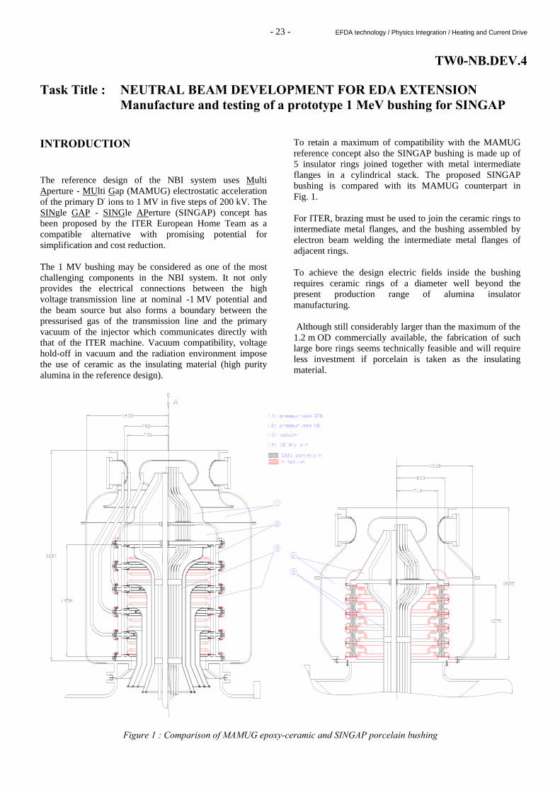
TW0-NB.DEV.4 Task Title : NEUTRAL BEAM DEVELOPMENT FOR EDA EXTENSION Manufacture and testing of a prototype 1 MeV bushing for SINGAP INTRODUCTION The reference design of the NBI system uses Multi Aperture - MUlti Gap (MAMUG) electrostatic acceleration of the primary D- ions to 1 MV in five steps of 200 kV. The SINgle GAP - SINGle APerture (SINGAP) concept has been proposed by the ITER European Home Team as a compatible alternative with promising potential for simplification and cost reduction. The 1 MV bushing may be considered as one of the most challenging components in the NBI system. It not only provides the electrical connections between the high voltage transmission line at nominal -1 MV potential and the beam source but also forms a boundary between the pressurised gas of the transmission line and the primary vacuum of the injector which communicates directly with that of the ITER machine. Vacuum compatibility, voltage hold-off in vacuum and the radiation environment impose the use of ceramic as the insulating material (high purity alumina in the reference design).
To retain a maximum of compatibility with the MAMUG reference concept also the SINGAP bushing is made up of 5 insulator rings joined together with metal intermediate flanges in a cylindrical stack. The proposed SINGAP bushing is compared with its MAMUG counterpart in Fig. 1. For ITER, brazing must be used to join the ceramic rings to intermediate metal flanges, and the bushing assembled by electron beam welding the intermediate metal flanges of adjacent rings. To achieve the design electric fields inside the bushing requires ceramic rings of a diameter well beyond the present production range of alumina insulator manufacturing. Although still considerably larger than the maximum of the 1.2 m OD commercially available, the fabrication of such large bore rings seems technically feasible and will require less investment if porcelain is taken as the insulating material.
Figure 1 : Comparison of MAMUG epoxy-ceramic and SINGAP porcelain bushing

- 24 - EFDA technology / Physics Integration / Heating and Current Drive
Radiation Induced Conductivity (RIC) experiments have shown that industrial IEC C221 porcelain is an alternative to the high purity alumina envisaged in the reference design. Also C221 has a thermal expansion coefficient very close to that of titanium, which should facilitate the porcelain to metal (Ti) brazing. The "physics" design has resulted in a relatively compact bushing incorporating electrostatic screens which prevent the porcelain from being hit by charged particles on the vacuum side and simultaneously produce low electric stresses at the junctions between porcelain, metal and vacuum (the triple points). RIC generated by radiation from the ITER plasma and the beams themselves has also an important impact on the choice of the pressurised gas in the transmission line and outside the bushing. For SF6, usually applied for its good voltage hold-off characteristics, a RIC value of 75 (±25) mA/Gy/s/bar/m3 has been predicted. For an estimated dose rate of 0.1 Gy/s, a volume of about 5 m3 and a pressure of 4 bar this would mean a (maximum) power loss of about 150 kW. Furthermore, SF6 is not compatible with the tritium re-processing and there could be adverse reactions with first wall materials. Thus using SF6 as the insulating gas demands a pressurised “guard gas” in an intermediate compartment between the vacuum and the SF6, which adds substantially to the complexity of the system.
An alternative to SF6 is dry air which has quite good properties in terms of radiation enhanced breakdown, quenching and RIC (1/5 of SF6 at the same pressure). However, from the measured Paschen curves, about a factor 3 higher pressure is required to obtain the same voltage hold-off as in SF6 at 1 MV. Based on the original design pressure of 4 bar SF6 one would require 12 bar in dry air. For this case the maximum RIC loss power is estimated at 90 kW. 2000 ACTIVITIES THE PROTOTYPE This ITER task is to design and fabricate a near to full scale SINGAP bushing mock-up and test it in the Cadarache 1 MV accelerator facility. The test bed imposes space restrictions, within which the design must fit, and the prototype bushing must yield conclusive results regarding the ITER bushing. A drawing of the proposed prototype bushing is shown in Fig. 2, and some details of the insulator and screen configuration are shown in Fig. 3. The prototype is only slightly smaller than the ITER bushing and the calculated electrostatic fields are slightly higher than those of the ITER bushing.
Figure 2 : Assembly of Cadarache 1 MV Porcelain SINGAP Bushing (1) concrete slab ceiling, (2) bushing tank lid, (3) HV transmission line centre conductor, (4) HV transmission line outer conductor, (5) top module cover flange, (6) bushing tank 4 bar SF6, (7) adapter flange, (8) reinforcement ribs, (9) beam vessel, vacuum, (10) bushing centre conductor)
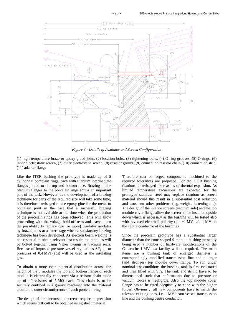
- 25 - EFDA technology / Physics Integration / Heating and Current Drive
Figure 3 : Details of Insulator and Screen Configuration (1) high temperature braze or epoxy glued joint, (2) location bolts, (3) tightening bolts, (4) O-ring grooves, (5) O-rings, (6) inner electrostatic screen, (7) outer electrostatic screen, (8) resistor groove, (9) connection resistor chain, (10) connection strip, (11) adapter flange Like the ITER bushing the prototype is made up of 5 cylindrical porcelain rings, each with titanium intermediate flanges joined to the top and bottom face. Brazing of the titanium flanges to the porcelain rings forms an important part of the task. However, as the development of a brazing technique for parts of the required size will take some time, it is therefore envisaged to use epoxy glue for the metal to porcelain joint in the case that a successful brazing technique is not available at the time when the production of the porcelain rings has been achieved. This will allow proceeding with the voltage hold-off tests and leaves open the possibility to replace one (or more) insulator modules by brazed ones at a later stage when a satisfactory brazing technique has been developed. As electron beam welding is not essential to obtain relevant test results the modules will be bolted together using Viton O-rings as vacuum seals. Because of imposed pressure vessel regulations SF6 up to pressures of 0.4 MPa (abs) will be used as the insulating gas. To obtain a more even potential distribution across the height of the 5 modules the top and bottom flange of each module is electrically connected via a resistor chain made up of 40 resistors of 5 MΩ each. This chain is to be securely confined in a groove machined into the material around the outer circumference of each porcelain ring. The design of the electrostatic screens requires a precision which seems difficult to be obtained using sheet material.
Therefore cast or forged components machined to the required tolerances are proposed. For the ITER bushing titanium is envisaged for reasons of thermal expansion. As limited temperature excursions are expected for the prototype stainless steel may replace titanium as screen material should this result in a substantial cost reduction and cause no other problems (e.g. weight, fastening etc.). The design of the interior screens (vacuum side) and the top module cover flange allow the screens to be installed upside down which is necessary as the bushing will be tested also with reversed electrical polarity (i.e. +1 MV c.f. -1 MV on the centre conductor of the bushing). Since the porcelain prototype has a substantial larger diameter than the cone shaped 9 module bushing presently being used a number of hardware modifications of the Cadarache 1 MV test facility will be required. The main items are a bushing tank of enlarged diameter, a correspondingly modified transmission line and a larger (and stronger) top module cover flange. To run under nominal test conditions the bushing tank is first evacuated and then filled with SF6. The tank and its lid have to be dimensioned such that deformation due to pressure or vacuum forces is negligible. Also the top module cover flange has to be rated adequately to cope with the higher forces. Obviously, all new components have to match the relevant existing ones, i.e. 1 MV beam vessel, transmission line and the bushing centre conductor.

- 26 - EFDA technology / Physics Integration / Heating and Current Drive
ELECTROSTATIC MODELLING Since the initial 1998 design the electrostatic modelling has been refined and the diameter of the centre conductor has reduced from 800 mm to 478 mm. As a consequence a welcome reduction in the size of the bushing has become possible. A desirable side effect of the reduction in size is that all radial dimensions of the SINGAP bushing could be made identical to those of the Cadarache prototype which will make the tests more relevant and conclusive. The majority of the of the electrostatic optimisation (screen curvatures and overall dimensioning) has been carried out with the SIMION 6 3D electrostatic field and particle code. Although this code does not treat dielectrics (nor space charge) it has proven a very useful tool as it allows rapid changes of geometry. The resulting design was then verified (especially in areas close to the insulator) against the OPERA 3D code from Vector Fields which allows a full but substantially more tedious treatment of electro-magnetic fields in the presence of dielectrics. With the SINGAP concept 2D cylindrical symmetry could be applied to give the highest possible spatial resolution in the areas of highest field stresses, i.e. the bottom part at the vacuum side and the top part at the pressurised gas side. The electrostatic design was guided by the following criteria. Electrostatic field stresses have been minimised (upper limit: 50 kV/cm at vacuum cathode areas, 60 – 100 kV/cm at pressurised gas cathode areas) by employing the maximum radii of curvature possible in each considered space envelope. Overlap of the electrostatic screens at the vacuum side prevents direct hits of electrons emitted from the surface of the centre conductor on any insulator. Furthermore, the screen and insulator shapes and geometries have been optimised to avoid or minimise electric field components perpendicular to the insulator surface. The refined shapes of the insulator and the electrostatic screens produce a slight field increase at the triple points which is partially be compensated for by reducing the insulator thickness from 130 to 120 mm. This brings the innner and outer screens closer together, but, the calculated fields of 1.9 kV/cm at the negative and 2.9 kV/cm at the positive triple points of the prototype bushing are still rather low values. STATUS The physics design of the prototype bushing has continued in parallel with the design of the SINGAP bushing for ITER and is essentially complete. From the design parameters it is expected that it will work satisfactorily and that the intended R&D programme will yield most of the results required. After the recent reduction of the centre conductor diameter in the ITER injector design the relevant dimensions of the two SINGAP bushings have become almost identical. In fact, the only item of any significance is the relative small difference in height, the ITER bushing is 220 mm higher than the prototype, which should result in the ITER bushing having a higher voltage withstand capability than the prototype. The voltage hold-off test results are therefore expected to be conclusive.
Due to the similarity of the two designs, know how and skills acquired during design and fabrication of the prototype can be directly applied to the subsequent production of the ITER bushing. The development of a brazing technique is considered to be a key point. A specification for the manufacture of the prototype including the development of an adequate brazing technique (porcelain to titanium) has been produced. This specification is to be completed by the engineering drawings and other accompanying documents necessary to start the European tender action under an EFDA article 7 contract (100% funding). The manufacture of 5 plus 1 spare 6th insulator module with epoxy glued intermediate flanges is estimated to take about 9 months from receipt of order. During this period the various parts necessary to produce a 7th brazed insulator module will be delivered with priority. The braze development itself should be limited to <12 months. TASK LEADER P. MASSMANN DSM/DRFC/SCCP/GIDN CEA Cadarache 13108 St Paul Lez Durance Cedex Tél. : 33 4 42 25 62 74 Fax : 33 4 42 25 62 33 E-mail : [email protected]

- 295 - Underlying technology / Vessel/In Vessel / Plasma facing components
UT-PFC&C-HFW Task Title : TRANSPARENT POLYCRISTALLINE CERAMICS INTRODUCTION The objective of this task is to develop transparent polycristalline ceramics for applications as diagnostic windows in a fusion reactor. Since environment of the window may vary, and the wave length of the signal analysed for diagnostic ranges from hundreds of nanometers to centimeter, different material may be used to optimize the performances for each application. Previous investigation enabled to successfully work out a process to obtain polycrystalline magnesium spinel MgAl2O4 exhibiting a wide range of optical transmission as well as good mechanical properties [1-2-3]. An alternative candidate that is now investigated is polycrystalline yttrium oxide (Y2O3) because it shows the potential of a large optical transmission from UV up to IR (cut off 9.5 µm) along with good mechanical properties. The process used for Y2O3 is the same than for MgAl2O4. It is based on powder technology that produces isotropic material and that is particularly well adapted to produce parts like windows or more complicated shapes. Literature shows good transmission properties for pure Y2O3 [4], but high temperature required to sinter pure yttrium oxide makes it very difficult to obtain transparent single crystal material with regular sintering. It is necessary to use a doping element. Previous results obtained with dilatometer [5] showed that addition of TiO2 as sintering aid gives rise to a decrease of about 200°C for the beginning of the sintering. Based on these results, TiO2 will be added to Y2O3 powder to decrease sintering temperature and have better chance to reduce grain size and structural defects in the sintered material. Also, for the same heating rate, the shrinkage rate is much higher and for the same dwell time and temperature, the remaining porosity is much lower when using the doped powder. One sample was post sintered in non optimized conditions to evaluate the optical performances of the doped material. Transmission spectrum was encouraging, but still needed to be improved compared to data in literature. 2000 ACTIVITIES Work performed at CE2M/LECMA aimed at optimizing the fabrication process to improve the transparency of polycrystalline Y2O3 specimens. Therefore, we started to study the introduction of doping element, then we optimized the doping content, and followed with the study of the influence of sintering and post sintering parameters on optical transmission.
FABRICATION PROCESSES OF TRANSPARENT POLYCRISTALLINE Y2O3 MATERIAL The key points to obtain transparent material by powder technology process is to keep in mind two objectives : homogeneity and defect free at any step. The main steps are the introduction of the doping element, where we aimed at mixing powders with the best homogeneity, avoiding pollution. Shaping the sample is the next step, where we paid particular attention to avoid pollution and to obtain homogeneous density across the sample without residual mechanical stress. Samples were sintered by heat treatment in air to close the porosity. During the sintering, grain size grows and we aimed at controlling this growth to obtain homogeneous grain size and homogeneous scattering of pore size across the sample with interganular position. Post densification was performed to eliminate the residual porosity down to sizes as far below micrometer scale as possible, and attention was paid to minimize stresses in the final sample. Doping powder and shaping samples TiO2 and Y2O3 powders are mixed in liquid medium, using ball mill. The liquid is then removed by heating under vacuum. The powder was crushed manually in a mortar and sieved. Characteristics of the new powder were measured. We noticed a slight increase of the specific surface area and a wider grain size distribution with average size two times lower than the raw powder. The reduction of the grain size should induce a higher reactivity to sintering. After drying and sieving, the powder was poured in latex bag to be compacted by cold isostatic pressing in a vessel filled with oil. The resulting cylinder shape had a total porosity around 55 vol%. Sintering Sintering started with low heating rate to gently eliminate volatile species from the surface of the powder and avoid crumbling of the sample. The heating rate and dwell temperature were then optimised to control the grain growth in acceptable length of time. The higher the temperature, the faster is the sintering, but the easier is the diffusion and the mobility of grain boundaries. Over sintering gives rise to heterogeneous grain growth with more emphasis when the grain size distribution of the starting powder is wide. Some samples, remaining from the batch fabricated for sintering optimisation, have been post sintered and their optical performances have been measured to study the influence of sintering parameters on optical properties.

- 296 - Underlying technology / Vessel/In Vessel / Plasma facing components
Post sintering Sintering aimed at closing the porosity to make the sample gas tight towards argon that is used in the HIP to apply isostatic pressure during heat treatment. If sintering parameters have been optimised to keep the structure homogeneous, HIP parameters must be optimised to eliminate remaining porosity while keeping homogeneous structure and without any residual stress in the material. During this work, we investigated the influence of HIP parameters like temperature and pressure on the optical performances of Y2O3 samples [6]. RESULTS Some samples containing different amount of TiO2 and sintered under different conditions, are observed with SEM. Their porosity was measured by immersion in alcohol, and by helium pycnometer for more accuracy on closed porosity results. Influence of TiO2 content The influence of TiO2 content in the range 0 – 5 wt% on sintering, was studied using dilatometer. Results showed that increasing the TiO2 content accelerates the shrinkage for a given sintering cycle. Porosity measurements and micrographs showed that for a given final density, part of closed porosity over total porosity changes with doping content. Increasing the doping content decreases the porosity at grain boundary and increases the grain size with lower homogeneity, and is likely to lead to a bimodal size distribution. Influence of sintering parameters On microstructure A study was made on the influence of the heating rate and of the dwell time on the microstructure of Y2O3. Micrographs showed a significant decrease of porosity for a given sintering temperature, with dwell time up to 5 hours, and almost no influence for longer dwell time. The fraction of small grains decreases with increasing dwell time (Figure 1). Very little effect was observed for the influence of the heating rate on the porosity and the grain size.
On optical properties Influence of parameters are studied while keeping the other sintering parameters constant. All the results showed higher sensitivity of transmission in the UV/Visible range, and almost no effect in IR range. Increasing dwell time for a given optimised sintering temperature, improves optical properties. For identical sintering cycles, increasing the TiO2 content under a limit of secondary phase formation, significantly increases optical transmission. For the highest TiO2 content we studied, results showed higher sensitivity of the transmission towards heating rate. Influence of post sintering parameters When HIP dwell temperature was increased, optical spectra of light transmission from UV to Visible showed a decreasing transmission level over the whole wavelength range (Figure 2). This result is related to significant grain growth observed by SEM.
Figure 2 : Influence of dwell HIP temperature on transmission in UV/visible range [6]
When HIP dwell pressure is increased, transparency is decreased with higher sensitivity in UV/Visible range. Increasing pressure by 200 b, lowers the transmission by 3 to 14%. The IR range is less sensitive to the pressure (Figure 3).
Dwell time of 1/4 hour Dwell time of 3 hours
Figure 1 : Influence of dwell time of natural sintering on the material microstructure [5]

- 297 - Underlying technology / Vessel/In Vessel / Plasma facing components
Figure 3 : Influence of the HIP pressure on transmission in UV/visible range [6]
CONCLUSION Transparent samples of Y2O3 can be produced using powder technology. The optical quality of the material can be improved by controlling homogeneity and purity of the powder and also by restraining the sample structure all along the process. This work aimed at studying the influence of main parameters at different steps of the process to maximise optical properties. Those parameters have been optimised. Results corroborate the potential of Y2O3 in terms of optical material to be used as window for diagnosis in fusion reactor. Evolution of optical properties under irradiation should be investigated. Part of the job in 2001 will be to deliver samples to DFRC for specific tests. REFERENCES [1] Potentialités de MgAl2O4 dans les machines de fusion,
F.Valin. 97-DT-048, 4/07/1997. [2] TG Spinel « M3 » Fabrication and characteristics of
MgAl2O4 disks supplied to DRFC, F.Valin. 98-DT-074, 24/04/1998.
[3] Transparent polycrystalline ceramic windows,
S.Fontaine 99-DT-133, 6/12/1999. [4] Transparent polycrystalline ceramic windows,
S.Fontaine 99-DT-120, 30/06/1999. [5] Study of sintering as a function of dopant content,
S.Fontaine, DTA/CEREM/CE2M/LECMA 00-DT-150, 19/06/2000.
[6] Optimization of the HIP cycle and measurement of
UV, visible, IR optical transmission of specimens, S.Fontaine, DTA/CEREM/CE2M/LECMA 00-DT-158, 31/10/2000.
TASK LEADER Nathalie LE BARS DRT/LIST/DECS/SE2M/DIR CEA Saclay 91191 Gif-sur-Yvette Cedex Tél. : 33 1 69 08 29 62 Fax : 33 1 69 08 91 75 E-mail : [email protected]