Annex A Bibliography
112
IEEE P3004.8 ™ /D1. 1 2 3 5 , June, 2010 October, 2011 June September November 2012 February 2013 IEEE P3004.8™/D1. 1 2 3 4 5 Draft Recommended Practice for Motor Protection in Industrial and Commercial Power Systems Sponsor Technical Book Coordinating Committee of the IEEE Industry Applications Society Approved <XX MONTH 20XX> IEEE-SA Standards Board Copyright © 2010 2 3 by the Institute of Electrical and Electronics Engineers, Inc. Three Park Avenue New York, New York 10016-5997, USA All rights reserved. This document is an unapproved draft of a proposed IEEE Standard. As such, this document is subject to change. USE AT YOUR OWN RISK! Because this is an unapproved draft, this document must not be utilized for any conformance/compliance purposes. Permission is hereby granted for IEEE Standards Committee participants to reproduce this document for purposes of international standardization consideration. Prior to adoption of this document, in whole or in part, by another standards development organization, permission must first be obtained from the IEEE Standards Activities Department ([email protected]). Other entities seeking Copyright © 2010 2011 2012 2013 IEEE. All rights reserved. This is an unapproved IEEE Standards Draft, subject to change. DCN 8-13-0010-00-CMTS Comments by Dan Ransom 02/28/2013 1 2 1 2 3 4 5 6 7 8 9 10 11 12 13 14 15 16 17 18 19 20 21 22 23 24 25 3 4
Transcript of Annex A Bibliography
IEEE P3004.8™/D1.1235, June, 2010October, 2011June September November2012February 2013
IEEE P3004.8™/D1.12345Draft Recommended Practice for Motor Protection in Industrial and Commercial Power Systems
Sponsor
Technical Book Coordinating Committeeof theIEEE Industry Applications Society
Approved <XX MONTH 20XX>
IEEE-SA Standards Board
Copyright © 201023 by the Institute of Electrical and Electronics Engineers, Inc.Three Park AvenueNew York, New York 10016-5997, USA
All rights reserved.
This document is an unapproved draft of a proposed IEEE Standard. As such, this document is subject to change. USE AT YOUR OWN RISK! Because this is an unapproved draft, this document must not be utilized for any conformance/compliance purposes. Permission is hereby granted for IEEE Standards Committee participants to reproduce this document for purposes of international standardization consideration. Prior to adoption of this document, in whole or in part, by another standards development organization, permission must first be obtained from the IEEE Standards Activities Department ([email protected]). Other entities seeking permission to reproduce this document, in whole or in part, must also obtain permission from the IEEE Standards Activities Department.
IEEE Standards Activities Department445 Hoes LanePiscataway, NJ 08854, USA
Copyright © 2010 201120122013IEEE. All rights reserved.This is an unapproved IEEE Standards Draft, subject to change.
DCN 8-13-0010-00-CMTS Comments by Dan Ransom02/28/2013
12
1
2
3
4
5
678
9
1011
121314
15
1617181920212223
242526
34

IEEE P3004.8™/D1.1235, June, 2010October, 2011June September November2012February 2013
Abstract: This recommended practice covers the protection of motors used in industrial and commercial power systems. It is likely to be of greatest value to the power-oriented engineer with limited experience in the area of protection and control. It can also be an aid to all engineers responsible for the electrical design of industrial and commercial power systems.
Keywords: <Select this text and type or paste keywords>
The Institute of Electrical and Electronics Engineers, Inc. 3 Park Avenue, New York, NY 10016-5997, USA Copyright © 20XX by the Institute of Electrical and Electronics Engineers, Inc. All rights reserved. Published <XX MONTH 20XX>. Printed in the United States of America.
IEEE is a registered trademark in the U.S. Patent & Trademark Office, owned by the Institute of Electrical and Electronics Engineers, Incorporated.
PDF: ISBN 978-0-XXXX-XXXX-X STDXXXXXPrint: ISBN 978-0-XXXX-XXXX-X STDPDXXXXX
IEEE prohibits discrimination, harassment and bullying. For more information, visit http://www.ieee.org/web/aboutus/whatis/policies/p9-26.html.No part of this publication may be reproduced in any form, in an electronic retrieval system or otherwise, without the prior written permission of the publisher.
Copyright © 2010 201120122013IEEE. All rights reserved.This is an unapproved IEEE Standards Draft, subject to change.
12
1234567
8
3456789
10111213141516
1718

IEEE P3004.8™/D1.1235, June, 2010October, 2011June September November2012February 2013
IEEE Standards documents are developed within the IEEE Societies and the Standards Coordinating Committees of the IEEE Standards Association (IEEE-SA) Standards Board. The IEEE develops its standards through a consensus development process, approved by the American National Standards Institute, which brings together volunteers representing varied viewpoints and interests to achieve the final product. Volunteers are not necessarily members of the Institute and serve without compensation. While the IEEE administers the process and establishes rules to promote fairness in the consensus development process, the IEEE does not independently evaluate, test, or verify the accuracy of any of the information or the soundness of any judgments contained in its standards.
Use of an IEEE Standard is wholly voluntary. The IEEE disclaims liability for any personal injury, property or other damage, of any nature whatsoever, whether special, indirect, consequential, or compensatory, directly or indirectly resulting from the publication, use of, or reliance upon this, or any other IEEE Standard document.
The IEEE does not warrant or represent the accuracy or content of the material contained herein, and expressly disclaims any express or implied warranty, including any implied warranty of merchantability or fitness for a specific purpose, or that the use of the material contained herein is free from patent infringement. IEEE Standards documents are supplied “AS IS.”
The existence of an IEEE Standard does not imply that there are no other ways to produce, test, measure, purchase, market, or provide other goods and services related to the scope of the IEEE Standard. Furthermore, the viewpoint expressed at the time a standard is approved and issued is subject to change brought about through developments in the state of the art and comments received from users of the standard. Every IEEE Standard is subjected to review at least every five years for revision or reaffirmation, or every ten years for stabilization. When a document is more than five years old and has not been reaffirmed, or more than ten years old and has not been stabilized, it is reasonable to conclude that its contents, although still of some value, do not wholly reflect the present state of the art. Users are cautioned to check to determine that they have the latest edition of any IEEE Standard.
In publishing and making this document available, the IEEE is not suggesting or rendering professional or other services for, or on behalf of, any person or entity. Nor is the IEEE undertaking to perform any duty owed by any other person or entity to another. Any person utilizing this, and any other IEEE Standards document, should rely upon his or her independent judgment in the exercise of reasonable care in any given circumstances or, as appropriate, seek the advice of a competent professional in determining the appropriateness of a given IEEE standard.
Interpretations: Occasionally questions may arise regarding the meaning of portions of standards as they relate to specific applications. When the need for interpretations is brought to the attention of IEEE, the Institute will initiate action to prepare appropriate responses. Since IEEE Standards represent a consensus of concerned interests, it is important to ensure that any interpretation has also received the concurrence of a balance of interests. For this reason, IEEE and the members of its societies and Standards Coordinating Committees are not able to provide an instant response to interpretation requests except in those cases where the matter has previously received formal consideration. A statement, written or oral, that is not processed in accordance with the IEEE-SA Standards Board Operations Manual shall not be considered the official position of IEEE or any of its committees and shall not be considered to be, nor be relied upon as, a formal interpretation of the IEEE. At lectures, symposia, seminars, or educational courses, an individual presenting information on IEEE standards shall make it clear that his or her views should be considered the personal views of that individual rather than the formal position, explanation, or interpretation of the IEEE.
Comments for revision of IEEE Standards are welcome from any interested party, regardless of membership affiliation with IEEE. Suggestions for changes in documents should be in the form of a proposed change of text, together with appropriate supporting comments. Recommendations to change the status of a stabilized standard should include a rationale as to why a revision or withdrawal is required. Comments and recommendations on standards, and requests for interpretations should be addressed to:
Secretary, IEEE-SA Standards Board445 Hoes LanePiscataway, NJ 08854USA
Authorization to photocopy portions of any individual standard for internal or personal use is granted by The Institute of Electrical and Electronics Engineers, Inc., provided that the appropriate fee is paid to Copyright Clearance Center. To arrange for payment of licensing fee, please contact Copyright Clearance Center, Customer Service, 222 Rosewood Drive, Danvers, MA 01923 USA; +1 978 750 8400. Permission to photocopy portions of any individual standard for educational classroom use can also be obtained through the Copyright Clearance Center.
Copyright © 2010 201120122013IEEE. All rights reserved.This is an unapproved IEEE Standards Draft, subject to change.
12
1234567
89
10
11121314
1516171819202122
2324252627
2829303132333435363738
3940414243
44
45
46
47
4849505152
34

IEEE P3004.8™/D1.1235, June, 2010October, 2011June September November2012February 2013
Introduction
This introduction is not part of IEEE P3004.8/D1.125, Draft Recommended Practice for Motor Protection in Industrial and Commercial Power Systems.
<Select this text and type or paste introduction text>
Notice to users
Laws and regulations
Users of these documents should consult all applicable laws and regulations. Compliance with the provisions of this standard does not imply compliance to any applicable regulatory requirements. Implementers of the standard are responsible for observing or referring to the applicable regulatory requirements. IEEE does not, by the publication of its standards, intend to urge action that is not in compliance with applicable laws, and these documents may not be construed as doing so.
Copyrights
This document is copyrighted by the IEEE. It is made available for a wide variety of both public and private uses. These include both use, by reference, in laws and regulations, and use in private self-regulation, standardization, and the promotion of engineering practices and methods. By making this document available for use and adoption by public authorities and private users, the IEEE does not waive any rights in copyright to this document.
Updating of IEEE documents
Users of IEEE standards should be aware that these documents may be superseded at any time by the issuance of new editions or may be amended from time to time through the issuance of amendments, corrigenda, or errata. An official IEEE document at any point in time consists of the current edition of the document together with any amendments, corrigenda, or errata then in effect. In order to determine whether a given document is the current edition and whether it has been amended through the issuance of amendments, corrigenda, or errata, visit the IEEE Standards Association web site at http://ieeexplore.ieee.org/xpl/standards.jsp, or contact the IEEE at the address listed previously.
For more information about the IEEE Standards Association or the IEEE standards development process, visit the IEEE-SA web site at http://standards.ieee.org.
Errata
Errata, if any, for this and all other standards can be accessed at the following URL: http://standards.ieee.org/reading/ieee/updates/errata/index.html. Users are encouraged to check this URL for errata periodically.
ivCopyright © 2010 20112013 IEEE. All rights reserved.
This is an unapproved IEEE Standards Draft, subject to change.
12
1
23
4
5
6
789
1011
12
1314151617
18
19202122232425
2627
28
293031
345
IEEE P3004.8™/D1.1235, June, 2010October, 2011June September November2012February 2013
Interpretations
Current interpretations can be accessed at the following URL: http://standards.ieee.org/reading/ieee/interp/index.html.
Patents
[If the IEEE has not received letters of assurance prior to the time of publication, the following notice shall appear:]
Attention is called to the possibility that implementation of this recommended practice may require use of subject matter covered by patent rights. By publication of this recommended practice, no position is taken with respect to the existence or validity of any patent rights in connection therewith. The IEEE is not responsible for identifying Essential Patent Claims for which a license may be required, for conducting inquiries into the legal validity or scope of Patents Claims or determining whether any licensing terms or conditions provided in connection with submission of a Letter of Assurance, if any, or in any licensing agreements are reasonable or non-discriminatory. Users of this recommended practice are expressly advised that determination of the validity of any patent rights, and the risk of infringement of such rights, is entirely their own responsibility. Further information may be obtained from the IEEE Standards Association.
[The following notice shall appear when the IEEE receives assurance from a known patent holder or patent applicant prior to the time of publication that a license will be made available to all applicants either without compensation or under reasonable rates, terms, and conditions that are demonstrably free of any unfair discrimination.]
Attention is called to the possibility that implementation of this recommended practice may require use of subject matter covered by patent rights. By publication of this recommended practice, no position is taken with respect to the existence or validity of any patent rights in connection therewith. A patent holder or patent applicant has filed a statement of assurance that it will grant licenses under these rights without compensation or under reasonable rates, with reasonable terms and conditions that are demonstrably free of any unfair discrimination to applicants desiring to obtain such licenses. Other Essential Patent Claims may exist for which a statement of assurance has not been received. The IEEE is not responsible for identifying Essential Patent Claims for which a license may be required, for conducting inquiries into the legal validity or scope of Patents Claims, or determining whether any licensing terms or conditions provided in connection with submission of a Letter of Assurance, if any, or in any licensing agreements are reasonable or non-discriminatory. Users of this recommended practice are expressly advised that determination of the validity of any patent rights, and the risk of infringement of such rights, is entirely their own responsibility. Further information may be obtained from the IEEE Standards Association.
vCopyright © 2010 20112013 IEEE. All rights reserved.
This is an unapproved IEEE Standards Draft, subject to change.
12
1
23
4
56
789
10111213141516
17181920
21222324252627282930313233
345

IEEE P3004.8™/D1.1235, June, 2010October, 2011June September November2012February 2013
Participants
At the time this draft recommended practice was submitted to the IEEE-SA Standards Board for approval, the Protection and Coordination Working Group of the technical Books Coordinating Committee of the Industrial and Commercial Power Systems Department of the Industry Applications Society had the following membership:
varWkGrpChair, ChairvarWkGrpViceChair, Vice Chair
Participant1Participant2Participant3
Participant4Participant5Participant6
Participant7Participant8Participant9
The following members of the <individual/entity> balloting committee voted on thistxtTrialUsetxtGorRPorSTD. Balloters may have voted for approval, disapproval, or abstention.
(to be supplied by IEEE)
Balloter1Balloter2Balloter3
Balloter4Balloter5Balloter6
Balloter7Balloter8Balloter9
When the IEEE-SA Standards Board approved this recommended practice on <XX MONTH 20XX>, it had the following membership:
(to be supplied by IEEE)<Name>, Chair
<Name>, Vice Chair<Name>, Past President
<Name>, Secretary
SBMember1SBMember2SBMember3
SBMember4SBMember5SBMember6
SBMember7SBMember8SBMember9
*Member Emeritus
Also included are the following nonvoting IEEE-SA Standards Board liaisons:
<Name>, NRC Representative<Name>, DOE Representative<Name>, NIST Representative
<Name>IEEE Standards Program Manager, Document Development
<Name>IEEE Standards Program Manager, Technical Program Development
viCopyright © 2010 20112013 IEEE. All rights reserved.
This is an unapproved IEEE Standards Draft, subject to change.
12
1
2345
6789
1011
121314
151617
18192021222324252627
282930
313233
34353637
383940414243444546
474849
505152
53
545556
57585960616263646566
345

IEEE P3004.8™/D1.1235, June, 2010October, 2011June September November2012February 2013
Contents
1. Scope............................................................................................................................................................1
2. Normative references....................................................................................................................................1
3. Definitions, abbreviations, and acronyms....................................................................................................21.1 Definitions.............................................................................................................................................21.1 Acronyms and abbreviations.................................................................................................................2
4. General discussion........................................................................................................................................24.1 Low-voltage systems.............................................................................................................................34.2 Medium-voltage systems.......................................................................................................................3
5. Factors to consider in protection of motors..................................................................................................35.1 Motor characteristics.............................................................................................................................35.2 Motor-starting conditions......................................................................................................................55.3 Ambient conditions................................................................................................................................55.4 Driven equipment..................................................................................................................................55.5 Power system quality.............................................................................................................................65.6 Motor importance..................................................................................................................................65.7 Load-side faults for motor controllers...................................................................................................65.8 Ground faults.........................................................................................................................................75.9 Maintenance capability and schedule....................................................................................................75.10 Service factor.......................................................................................................................................7
6. Types of protection.......................................................................................................................................86.1 Purpose of motor protection..................................................................................................................86.2 Abnormal power supply conditions (undervoltage protection).............................................................8
6.2.1 Undervoltage (Device 27)...................................................................................86.2.2 Instantaneous or time delaydelay........................................................................96.2.3 With latching contactor or circuit breaker..........................................................96.2.4 With ac magnetically held main contactor.......................................................106.2.5 With dc magnetically held main contactor.......................................................106.2.6 Voltage-sensing relays......................................................................................10
6.3 Phase unbalance protection (Device 46, current) (Device 47, voltage) )(Device 60).........................116.3.1 Purpose.............................................................................................................116.3.2 Single phasing...................................................................................................116.3.3 Instantaneous or time delaydelay......................................................................126.3.4 Relays...............................................................................................................12
6.4 Overcurrent protection (Device 51, inverse time) (Device 50, instantaneous)...................................126.5 Multifunction relay (Device 11)..........................................................................................................13
7. Low-voltage motor protection....................................................................................................................137.1 Low-voltage motor overcurrent protection..........................................................................................14
7.1.1 Thermal and electronic overload relays............................................................147.1.2 Time-delay (or dual-element) fuses..................................................................157.1.3 Inverse-time circuit breakers............................................................................157.1.4 Instantaneous trip circuit breakers (or motor circuit protectors)......................15
7.2 Low-voltage motor ground-fault protection........................................................................................17
viiCopyright © 2010 20112013 IEEE. All rights reserved.
This is an unapproved IEEE Standards Draft, subject to change.
12
1
2
3
456
789
1011121314151617181920
21222324252627282930313233343536
37383940414243
345

IEEE P3004.8™/D1.1235, June, 2010October, 2011June September November2012February 2013
7.2.1 Solidly grounded systems.................................................................................187.2.2 Low-resistance-grounded systems....................................................................187.2.3 High-resistance-grounded systems...................................................................18
7.3 Low-voltage motor stator winding over temperature..........................................................................187.3.1 Thermostat winding over-temperature devices................................................197.3.2 Thermistor winding over-temperature devices.................................................197.3.3 Resistance temperature detector (RTD) winding over-temperature devices....19
7.4 Low-voltage motor undervoltage protection.......................................................................................197.4.1 Undervoltage relays..........................................................................................207.4.2 Undervoltage sensors for circuit breakers........................................................20
8. Medium-voltage motor protection..............................................................................................................208.1 Medium-voltage motor overcurrent protection...................................................................................208.2 Fault protection....................................................................................................................................25
8.2.1 Motor overcurrent differential relay (Device 87).............................................258.2.1.1 Conventional phase differential overcurrent relay...............................................25
8.2.1.2 Self-balancing differential using window CTs........................................................26
8.2.2 Split winding current unbalance (Device 87)...................................................278.2.2.1 Purpose.................................................................................................................27
8.2.2.2 Arrangement of CTs and relays.............................................................................27
8.2.2.3 Evaluation of split windingsplit-winding current unbalance protection................27
8.2.2.4 Application of split windingsplit-winding protection............................................28
8.2.3 Ground-fault protection....................................................................................288.2.3.1 Purpose.................................................................................................................28
8.2.3.2 Instantaneous ground-fault protection.................................................................28
8.2.3.3 Time-overcurrent ground-fault protection...........................................................29
8.2.3.4 Installation of cable for ground-fault protection...................................................29
8.2.3.5 Residually connected CTs and ground-fault relay.................................................29
8.2.3.6 Selection of resistor for low-resistance system grounding...................................30
8.3 Monitors...............................................................................................................................................308.3.1 Stator winding over temperature......................................................................308.3.2 RTDs.................................................................................................................30
8.3.2.1 Thermocouples.....................................................................................................31
8.3.2.2 Thermistors...........................................................................................................31
8.3.2.3 Thermostats and temperature bulbs....................................................................31
8.3.2.4 Application of stator winding temperature protection.........................................31
8.3.3 Rotor over temperature.....................................................................................328.3.3.1 Synchronous motors.............................................................................................32
8.3.3.2 Wound-rotor induction motor-starting resistors..................................................32
viiiCopyright © 2010 20112013 IEEE. All rights reserved.
This is an unapproved IEEE Standards Draft, subject to change.
12
123456789
10
1112131415
16
1718
19
20
21
2223
24
25
26
27
2829303132
33
34
35
3637
38
345
IEEE P3004.8™/D1.1235, June, 2010October, 2011June September November2012February 2013
8.3.4 Mechanical and other protection......................................................................328.3.4.1 Motor bearing and lubricating systems................................................................32
8.3.4.2 Ventilation and cooling systems...........................................................................33
8.3.4.3 Liquid detectors....................................................................................................33
8.3.4.4 Fire detection and protection...............................................................................33
8.3.4.5 Partial discharge detectors...................................................................................33
8.3.5 Vibration monitors and sensors........................................................................348.3.5.1 Purpose of vibration monitoring...........................................................................34
8.3.5.2 Transducers...........................................................................................................34
8.3.5.3 Proximity transducers...........................................................................................34
8.3.5.4 Monitors...............................................................................................................37
8.3.5.5 Diagnostic systems................................................................................................38
8.4 Synchronous motor protection.............................................................................................................398.4.1 Damper winding protection..............................................................................398.4.2 Field-current failure protection.........................................................................398.4.3 Excitation voltage availability..........................................................................408.4.4 Pullout protection (Device 55)..........................................................................408.4.5 Incomplete starting sequence (Device 48)........................................................40
8.4.5.1 Operation indicator for protection devices...........................................................41
8.4.5.2 Induction motor protection..................................................................................41
8.5 Protection against excessive starting...................................................................................................418.6 Rotor winding protection.....................................................................................................................41
8.6.1 Synchronous motors.........................................................................................418.6.2 Wound-rotor induction motors.........................................................................42
8.7 Lightning and surge protection............................................................................................................428.7.1 Types of protection...........................................................................................428.7.2 Locations of surge protection...........................................................................448.7.3 Application of surge protection........................................................................44
8.8 Protection against overexcitation from shunt capacitance..................................................................448.8.1 Nature of problem.............................................................................................448.8.2 Protection..........................................................................................................45
8.9 Protection against automatic reclosing or automatic transfer..............................................................468.9.1 Nature of problem.............................................................................................468.9.2 Protection..........................................................................................................46
8.10 Protection against excessive shaft torques.........................................................................................478.11 Protection against excessive shaft torques developed during transfer of motors between out-of-phase sources.............................................................................................................................................478.12 Protection against failure to rotate.....................................................................................................48
8.12.1 Failure to rotate...............................................................................................488.12.2 Reverse rotation..............................................................................................49
9. Application considerations.........................................................................................................................499.1 Motor protection for ASD applications...............................................................................................49
ixCopyright © 2010 20112013 IEEE. All rights reserved.
This is an unapproved IEEE Standards Draft, subject to change.
12
12
3
4
5
6
78
9
10
11
1213141516171819
202122232425262728293031323334353637383940
4142
345

IEEE P3004.8™/D1.1235, June, 2010October, 2011June September November2012February 2013
9.1.1 Terminology.....................................................................................................499.1.2 Low Voltage AC Drive Motor Protection........................................................49
9.1.2.1 Protection.............................................................................................................50
9.1.2.2 Included in ASD.....................................................................................................50
9.1.2.3 Bypass Circuits......................................................................................................51
9.1.2.4 Multiple Motor Applications.................................................................................51
9.1.2.5 Overtemperature Protection................................................................................51
9.1.3 Medium Voltage AC Drive Motor Protection..................................................529.1.4 DC Drive Motor Protection..............................................................................529.1.5 Other Considerations........................................................................................52
9.1.5.1 Shaft Voltage and Bearing Currents and Common Mode Voltages.......................52
9.1.5.2 Partial Discharge...................................................................................................52
9.1.5.3 ASD Output filters and reactors............................................................................52
9.1.5.4 NEMA MG-1 Part 30 and 31 Inverter Duty............................................................53
9.1.6 Selecting Drives................................................................................................539.1.6.1 Selection Considerations.......................................................................................53
9.1.6.2 Regeneration and Dynamic Braking......................................................................54
9.1.7 Drive Protection................................................................................................549.2 Motor protection for hazardous (classified) locations.........................................................................559.3 DC Motor protection...........................................................................................................................55
Annex A Bibliography..................................................................................................................................56
Annex B Protection setting considerations.....................................................................................................57B.1 Typical motor protection settings.......................................................................................................57B.2 Current unbalance and ground fault protection in HRG system.........................................................57B.3 Overcurrent protection in fixed capacitor applications.......................................................................57
xCopyright © 2010 20112013 IEEE. All rights reserved.
This is an unapproved IEEE Standards Draft, subject to change.
12
123
4
5
6
7
89
1011
12
13
14
1516
17
181920
21
2223242526
345

IEEE P3004.8/D1.12, June, 2010October 2011June 2012February 2013
Draft Recommended Practice for Motor Protection in Industrial and Commercial Power Systems
IMPORTANT NOTICE: This standard is not intended to ensure safety, security, health, or environmental protection in all circumstances. Implementers of the standard are responsible for determining appropriate safety, security, environmental, and health practices or regulatory requirements.
This IEEE document is made available for use subject to important notices and legal disclaimers. These notices and disclaimers appear in all publications containing this document and may be found under the heading “Important Notice” or “Important Notices and Disclaimers Concerning IEEE Documents.” They can also be obtained on request from IEEE or viewed at http://standards.ieee.org/IPR/disclaimers.html.
1. Scope
This recommended practice covers the protection of motors used in industrial and commercial power systems. It is likely to be of greatest value to the power-oriented engineer with limited experience in the area of protection and control. It can also be an aid to all engineers responsible for the electrical design of industrial and commercial power systems.
2. Normative references
<Lorraine Padden (lead), Paul Cardinal . Review dated/non-dated references. Date in text where quotes or references are used. > The following referenced documents are indispensable for the application of this document (i.e., they must be understood and used, so each referenced document is cited in text and its relationship to this document is explained). For dated references, only the edition cited applies. For undated references, the latest edition of the referenced document (including any amendments or corrigenda) applies.
API Std 541-1995, Form-Wound Squirrel Cage Induction Motors—250 Horsepower and Larger.
API Std 546-1997, Brushless Synchronous Machines—500 kVA and Larger.
IEC 60947-4-1-2000, Low-Voltage Switchgear and Controlgear, Part 4: Contactors and Motor Starters, Section One—Electromechanical Contactors and Motor-Starters.
1
1
2
3
4567
89
101112
13
14151617
18
1920212223
24
25
2627
2

IEEE P3004.8/D1.12, June, 2010October 2011June 2012February 2013
IEEE Std 141-1993 (Reaff 1999), IEEE Recommended Practice for Electric Power Distribution for Industrial Plants (IEEE Red Book).
IEEE Std 241-1990 (Reaff 1997), IEEE Recommended Practice for Electric Power Systems in Commercial Buildings (IEEE Gray Book).
IEEE Std 1015-1997, IEEE Recommended Practice for Applying Low-Voltage Circuit Breakers Used in Industrial and Commercial Power Systems (IEEE Blue Book).
IEEE Std. 1349-2011, IEEE Guide for the Application of Electric Motors in Class I, Division 2 and Class I, Zone 2 Hazardous (Classified) Locations
IEEE Std C37.2-1996, IEEE Standard Electrical Power System Device Function Numbers.
IEEE Std C37.17-1997, Trip Devices for AC and General Purpose DC Low-Voltage Power Circuit Breakers.
IEEE Std C37.96-2000, IEEE Guide for AC Motor Protection.
NEMA ICS 2-2000, Industrial Control and Systems Controllers, Contactors and Overload Relays Rated 600 Volts.
NEMA MG 1-1998 (Revision 1, 2000), Motors and Generators.
NFPA 20-1999, Standard for the Installation of Centrifugal Fire Pumps.
NFPA 70-1999, National Electrical Code® (NEC®).
3. Definitions , abbreviations, and acronyms
For the purposes of this document, the following terms and definitions apply. The IEEE Standards Dictionary: Glossary of Terms & Definitions should be referenced for terms not defined in this clause.1
[BB46] <check IEEE 100 as reference document>
3.1 Definitions
abnormal operating condition: As applied to motors, including, but not limited to, starting, locked rotor, voltage unbalance, overload, and short-circuit. As applied to equipment in classified locations, equipment failure is considered to be an abnormal operating condition.
adjustable speed drive: an electric drive designed to provide easily operable means for speed adjustment of the motor, within a specified speed range. (See IEEE 100)
ambient temperature: Ambient temperature is the temperature of the surrounding cooling medium, such as gas or liquid, which comes into contact with the heated parts of the apparatus (See NEMA MG-1)
1 The IEEE Standards Dictionary: Glossary of Terms & Definitions is available at http://shop.ieee.org/.
1
12
34
56
78
9
1011
12
1314
15
16
17
18
192021
22
23242526
2728
293031
2
3
IEEE P3004.8/D1.12, June, 2010October 2011June 2012February 2013
approved: Acceptable to the authority having jurisdiction.2
autoignition temperature (AIT): The minimum temperature required to initiate or cause self-sustained combustion of a solid, liquid, or gas independently of the heating or heated element.3
Class B rise: Based on a maximum 40C ambient, a motor stator temperature rise at 1.0 service factor of 80C (measured by resistance) or 80C, 85C, or 90C (measured by embedded detectors) in accordance with NEMA MG-1-2009 (Revision 1-2010),4
depending on the motor size, motor type, enclosure type, and voltage rating. The rise at 1.0 service factor corresponds to Class B type of insulation system in the NEMA MG-1-2009 (Revision 1-2010) temperature rise tables.
Common Mode Voltage: In the context of Adjustable Speed Drives, Common Mode Voltage (CMV) is the displacement of the neutral point (and each phase voltage) of the ASD output from ground due to the switching of the solid state devices in the drive. It is an alternating voltage whose magnitude and frequency components are dependent on the drive topology. All present drive topologies create CMV to some extent. CMV can also be created at the motor if phase circuit conductors, unsymmetrical with respect to the equipment grounding conductor(s) or grounded sheaths or raceways, are used between the ASD output and the motor.
continuous duty: operation at a substantially constant load for an indefinitely long time. This is also known as continuous rating in NEMA MG-1.
corona: A type of localized discharge resulting from transient gaseous ionization on an insulation system when the voltage stress exceeds a critical value. The ionization is usually localized over a portion of the distance between the electrodes of the system. (Corona activity can result in surface discharges and surface tracking on motor windings.) Corona is visible partial discharges in gases adjacent to a conductor. (See IEEE 1434 [B51])
explosionproof equipment: Equipment enclosed in a case that is capable of withstanding an explosion of a specified gas or vapor that may occur within it and of preventing the ignition of a specified gas or vapor surrounding the enclosure by sparks, flashes, or explosion of the gas or vapor within, and that operates at such an external temperature that a surrounding flammable atmosphere will not be ignited thereby.5
exposed surface: A surface that is internal to an enclosure or an external surface of an enclosure which could be exposed to the surrounding flammable atmosphere, without the benefit of an enclosure that would contain an explosion or exclude the hazardous gas. (An exposed internal surface may be the rotor, stator, or space heater surfaces of open
2 See footnote 3.
3 Reprinted with permission from NFPA 497, Recommended Practice for the Classification of Flammable Liquids, Gases or Vapors and of Hazardous (Classified) Locations for Electrical Installations in Chemical Process Areas Copyright © 2008, National Fire Protection Association, Quincy, MA. This reprinted material is not the complete and official position of the NFPA on the reference subject which is represented only by the standard in its entirety.
4 Information on references can be found in Clause 2.
5 See Footnote 3.
1
1
234
56789
10
1112131415161718
1920
212223242526
2728293031
32333435
2
3456
7
8
9
IEEE P3004.8/D1.12, June, 2010October 2011June 2012February 2013
and TEFC motors. An exposed external surface is the exterior surface, which could be exposed to the surrounding flammable atmosphere such as the exterior surface of explosionproof, pressurized, or force ventilated enclosures.)
identified: (as applied to equipment). Recognizable as suitable for the specific purpose, function, use, environment, application, and so forth, where described in a particular Code requirement.6
IC Code: The IC Code designates the method of electrical machine cooling as described in NEMA MG-1, Part 6.
IP Code: The IP Code designates the degree of protection provided by the enclosure of a rotating machine as described in NEMA MG-1, Part 5.
listed: Equipment, materials, or services included in a list published by an organization that is acceptable to the authority having jurisdiction and concerned with evaluation of products or services, that maintains periodic inspection of production of listed equipment or materials or periodic evaluation of services, and whose listing states that either the equipment, material, or service meets appropriate designated standards or has been tested and found suitable for a specified purpose.7
multisection motor: A motor whose construction utilizes a component block approach in the assembly of the enclosure, that is, the enclosure has a number of bolted joints which could connect together the stator frame, the ventilation hood, the motor base, the bearing supports, and enclosure covers.
NEMA frame: This refers to the NEMA MG-1 system of a standardized frame designation for AC machines including 449 frame size and smaller. NEMA MG-1-2009 (Revision 1-2010), Part 4 provides critical mounting dimensions for each frame size.
normal operating condition: As applied to motors, a normal operating condition is operating at rated full-load steady state conditions.11 Locked-rotor, starting, single-phasing, and operating above base nameplate kilowatt or horsepower are not normal operating conditions.
overload: Loading in excess of normal rating of equipment. For a motor, it is considered overloaded when operated above its base nameplate kilowatt or horsepower.
partial discharge: A localized electric discharge resulting from ionization in an insulation system when the voltage stress exceeds the critical value. This discharge partially bridges the insulation in the voids internal to the motor winding insulation.
per unit torque (as applied in Annex H): Per unit torque is the test value of load torque divided by the motor rated torque at nameplate rated conditions, such as rated voltage and rated frequency.
service factor: A multiplier that, when applied to the rated power, indicates a permissible power loading that may be carried under the conditions specified for the service factor.
6 See Footnote 3.
7 See Footnote 3.
1
123
456
78
910
111213141516
17181920
212223
24252627
2829
303132
333435
3637
2
3
4
IEEE P3004.8/D1.12, June, 2010October 2011June 2012February 2013
spark: A sudden and irreversible transition from a stable corona discharge to a stable arc discharge. It is a luminous electrical discharge of short duration between two electrodes in an insulating medium. It is generally brighter and carries more current than corona, and its color is mainly determined by the type of insulating medium. It generates radio noise of wider frequency spectrum (extending into hundreds of megahertz) and wider magnitude range than corona. A spark is not classified as corona. Sparking can also include static discharge, sparking due to mechanical contact, and capacitive discharges (ie. across bearing oil film and separating switch contacts).
3.2 Acronyms and abbreviations
AFD adjustable frequency drive (ASD is the IEEE preferred term)AHJ authority having jurisdictionAIT autoignition temperatureAPI American Petroleum InstituteASD adjustable speed driveASTM American Society for Testing and MaterialsCEC Canadian Electrical CodeCENELEC European Committee for Electrotechnical StandardizationCMV Common Mode VoltageCSA Canadian Standards Association InternationalDPFV Drip-Proof Forced VentilatedFLC full-load currentFLT full-load torqueFPN Fine Print Note (formerly used in the National Electrical Code®)HRG High Resistance GroundIC IC CodeIEC International Electrotechnical CommissionIP IP CodeLCI Load Commutated Inverter LFL lower flammable limitLRC locked rotor currentLVPCB low-voltage power circuit breakerMCCB molded-case circuit breakerMESG maximum experimental safe gapMIC minimum igniting currentMIE minimum ignition energyMOV metal oxide varistorNEC National Electrical CodeNEMA National Electrical Manufacturers AssociationNFPA National Fire Protection AssociationNRTL Nationally Recognized Testing LaboratoryODE opposite drive endODP open dripproofOEM original equipment manufacturerPWM pulse-width modulation
1
12345678
9
1011121314151617181920212223242526272829303132333435363738394041424344
2

IEEE P3004.8/D1.12, June, 2010October 2011June 2012February 2013
RP recommended practiceRPM revolutions per minuteRTD resistance temperature detectorSCR silicon controlled rectifierSF service factorT Code Temperature Code or Identification Number per 2011 NEC Table
500.8(C)TEAAC totally enclosed air-to-air cooledTEFC totally enclosed fan cooledTEFV totally enclosed force-ventilatedTENV totally enclosed nonventilatedTEPV totally enclosed pipe-ventilatedTEWAC totally enclosed water-to-air cooledTFE tetrafluoroethyleneUFL upper flammable limitUL Underwriters Laboratories Inc.VFD Variable Frequency Drive (ASD is the IEEE preferred term)VSD Variable Speed Drive (ASD is the IEEE preferred term)WPI weather protected Type IWPII weather protected Type II
4. General discussion
This recommended practice applies specifically to three-phase integral horsepower motors. Many factors should be considered in choosing motor protection: motor importance, motor rating (from one to several thousand horsepower), thermal limit of rotor or stator, environment, power system source and its neutral grounding method, type of motor controller, etc. Protection for each specific motor installation should meet the requirements of the application. Power quality of the plant distribution system should be given appropriate attention, especially with regard to voltage sags and surges, harmonics, service interruptions, and operation of distribution line reclosers. Items in 10.2Clause 5 and 10.3 Clause 6 should be considered as checklists when deciding upon protection for a given motor installation. After the types of protection have been selected, manufacturers’ bulletins should be studied to ensure proper application of the specific protection chosen.
4.1 Low-voltage systems
Low-voltage systems are nominally 1000 V or less. Table 3-11 of the IEEE Std 141-1993 NEMA MG-1 lists the standard motor nameplate ratings along with the preferred horsepower size limits for the several standard motor voltages. At present, a maximum of 575 V and 750 kW exists for motor nameplate ratings. <check on the size and voltage with NEMA reference>
4.2 Medium-voltage systems
Medium-voltage systems range from above 1000 V and up to 69 kV. Industrial and commercial power systems operate with distribution voltages of 2.4 kV, 4.16 kV, 6.9 kV, and 13.8 kV and above. The
1
123456789
101112131415161718192021
22
23242526272829303132
33
34353637
38
3940
2
IEEE P3004.8/D1.12, June, 2010October 2011June 2012February 2013
selection of the motor voltages is described in Chapter 3 of IEEE Std 141-1993. <check, include or remove>
5. Factors to consider in protection of motors
The factors in 10.25.1 through 10.25.10 should be considered when selecting motor protection.
5.1 Motor characteristics
Motor characteristics include type, speed, voltage, horsepower rating, service factor, NEMA design (i.e., A, B, C, or D, or E, which are the torque and speed characteristics for low- and medium-voltage motors as described in NEMA MG 1-1998), application, power factor rating, type of motor enclosure, bearing lubrication types, arrangement of windings and their temperature limits, thermal capabilities of rotor and stator during starting, running, and stall conditions. See Table 1.
1
12
3
4
5
6789
10
2

IEEE P3004.8/D1.12, June, 2010October 2011June 2012February 2013
Table 1—Typical characteristics and applications offixed frequency medium ac squirrel-cage motors <Ed Larsen, get permission from NEMA,
update table.>
Polyphase characteristics
Locked- rotor
torque (percent
rated load torque)
Pull-up torque
(percent rated load
torque)
Breakdown torque
(percent rated load
torque)
Locked- rotor
current (percent
rated load current)
Slip Typical applications
Relative efficiency
Design ANormal locked rotor torque and high locked rotor current
70–275a 65–190a 175–300 Not defined 0.5–5%
Fans, blowers, centrifugal pumps and compressors, motor-generator sets, etc., where starting torque requirements are relatively low
Medium or high
Design BNormal locked-rotor torque and normal locked-rotor current
70–275a 65–190a 175–300a 600–800 0.5–5%
Fans, blowers, centrifugal pumps and compressors, motor-generator sets, etc., where starting torque requirements are relatively low
Medium or high
Design C High locked-rotor torque and normal locked-rotor current
200–285a 140–195a 190–225a 600–800 1–5%
Conveyors, crushers, stirring machines, agitators, reciprocating pumps and compressors, etc., where starting under load is required
Medium
Design DHigh locked-rotor torque and high slip
275 Not defined 275 600–800 Š5%
High peak loads with or without flywheels such as punch presses, shears, elevators, extractors, winches, hoists, oil-well pumping and wire-drawing machines
Medium
IEC Design HHigh locked rotor torque and high locked rotor current
200–285a 140–195a 190–225a 800–1000 1–5% Conveyors, crushers, stirring machines, agitators, reciprocating pumps and compressors, etc., where starting under load is required
Medium
IEC Design NNormal locked-rotor torque and high locked rotor current
70–190a 60–140a 160–200a 800–1000 0.5–3% Fans, blowers, centrifugal pumps and compressors, motor-generator sets, etc., where starting torque requirements are relatively low
Medium or high
NOTE—These typical characteristics represent common usage of the motors—for further details consult the specific performance standards for the complete requirements.Reprinted from NEMA MG10-2001 by permission of the National Electrical Manufacturers Association.aHigher values are for motors having lower horsepower ratings.
1
1
234
5
2

IEEE P3004.8/D1.12, June, 2010October 2011June 2012February 2013
5.2 Motor-starting conditions
Motor-starting conditions include full voltage or reduced voltage, adjustable speed drive (ASD), voltage drop and degree of inrush current during starting, repetitive starts, and frequency and total number of starts. See Figure 1 and Padden and Pillai [B10].
Figure 1— Typical motor-starting and capability curves(specific motor terminal voltage and for cold start)
5.3 Ambient conditions
Ambient conditions include maximum and minimum temperatures, altitude, adjacent heat sources, and ventilation arrangement.
5.4 Driven equipment
Load characteristics are important in the selection of the motor; otherwise, the driven equipment may lead to locked rotor, failure to reach normal speed, excessive heating during acceleration, overloading, and stalling. See Figure 2, which illustrates the relationship between the accelerating current of a motor versus the thermal damage limits of the motor during accelerating and running conditions. Present practice is to add an electronic reduced-voltage starter for motors that may have accelerating problems or to add an ASD for motors that could be operated at a reduced speed for some reasonable period of the duty cycle. The protection of ASDs is not discussed in this recommended practice. For a detailed study of reduced-voltage starting, read Chapter 7 of IEEE Std 241-1990. <check with motor manufacturer; add ASD reference>
1
1
234
567
8
910
11
1213141516171819
2
IEEE P3004.8/D1.12, June, 2010October 2011June 2012February 2013
Figure 2— Typical time-current and thermal limit characteristic curves
5.5 Power system quality
Power system quality issues include types of system grounding, exposure to lightning and switching surges, capacitors and their controls for power factor correction, fault capacity, exposure to automatic reclosing or transfer, possibilities of single-phase supply (e.g., broken conductor, open disconnect switch or circuit breaker pole, blown fuse), and other loads that can cause voltage unbalance. Another factor is harmonics, which may cause motor overheating and affect the performance of electronic protective devices. <maybe add reference>
5.6 Motor importance
Factors that determine motor importance include motor cost, forced outage costs, amount of maintenance and operating supervision to be provided, and ease and cost of repair or replacement. A motor that is important to a plant’s operating continuity or process safety should include a pre-trip alarm for operator intervention as a first step. An example is to initiate an alarm when a ground fault is detected on high-resistance-grounded neutral low-voltage systems. This scheme can also be applied to medium-voltage systems below 13.8 kV; but at the 13.8 kV voltage level, use of a trip, rather than alarm, is preferred.
5.7 Load-side faults for motor controllers
Although most of this subclause concerns low-voltage applications, the principles apply to medium-voltage applications of motor controllers, as well. Calculation of available fault current in a circuit is described in
1
12
3
456789
10
111213141516
17
1819
2

IEEE P3004.8/D1.12, June, 2010October 2011June 2012February 2013
Chapter 2. Fuse and circuit breaker protection for conductors in feeder and branch circuits are described in Chapter 5, Chapter 6, and Chapter 7.
NOTE—Fuses and circuit breakers are rated for connection to available fault current sources on the basis of protecting the conductors on the load side of the circuit breaker or fuse.
In a motor controller, the above philosophy does not necessarily extend to protect the motor controller or its compartment. For proper protection of the motor controller, the fuse or circuit breaker (or motor circuit protector) that the controller manufacturer has had tested by a nationally recognized testing laboratory (NRTL) for the rated fault current available at its line terminals should be used. A motor circuit protector has an instantaneous-only trip element, similar in construction to a molded-case circuit breaker (MCCB), and is defined in 10.47.1.4.
Such motor controllers for best results should bear an NRTL listing for connection to available currents higher than the currents found in the power supply of the plant system under consideration or projected plant expansion fault duty. The NRTL-listed controller may still be substantially damaged by a load-side fault downstream of the controller. If protection is necessary to minimize damage to the controller itself, the controller manufacturer should be consulted, or Type 2 protection should be specified in accordance with IEC 60947-4-1-2000. Type 1 protection will prevent major damage but replacement of some motor control center components may be necessary after fault occurs.
Controllers should be protected with fuses or circuit breakers rated for the available fault current.,. This subject is covered more thoroughly under protection of low-voltage motors in 7.1.
Controllers connected to available currents above 10 000 A symmetrical should be provided with fuses or circuit breakers rated to interrupt a fault at least equal to the line terminal fault current, with provisions to prevent substitution of underrated fuses or circuit breakers. This subject is covered more thoroughly under protection of low-voltage motors in 10.47.1.
Ground faults
Ground faults often start at a low current level and, if allowed to continue, lead to more extensive damage. Whether an arcing or bolted fault, the initial damage is to motor windings, but, if allowed to continue, could cause serious damage to the motor core. The cost to repair or replace would then be more expensive. This subject is treated in more depth in Chapter 8.
5.8 Maintenance capability and schedule
Maintenance capability and schedule are important factors. Selection of complex protection that cannot or will not be appropriately maintained can lead to inadequate protection. Likewise, the selection and setting of overload protection do not prevent inadvertent setting changes due to normal vibration or ambient conditions. Backup protection should be coordinated to operate if primary protection fails to operate. Maintenance is covered in Chapter 16. <delete, or find reference>
5.9 Service factor
The service factor of an ac motor is a multiplier which, when applied to the rated horsepower, indicates a permissible horsepower loading that may be carried under the conditions specified for the service factor (see NEMA MG 1-1998). <-2011 Section 1, 1.42; 14.37 for standard conditions.>
1
12
34
56789
10
11121314151617
1819
20212223
24
25262728
29
3031323334
35
363738
2

IEEE P3004.8/D1.12, June, 2010October 2011June 2012February 2013
6. Types of protection
6.1 Purpose of motor protection
In a power system, the basic premise is that the delivered power is of acceptable quality to satisfy the needs of the facility. However, an abnormal condition can exist due to plant conditions or the external power supply. Depending upon the plant size and location, conditions such as voltage transients, surges or sags, over-frequency or under-frequency, harmonics, or discontinuity may develop that require corrective action. For large facilities, the incoming power is likely monitored, and means have probably been taken to protect the facility from abnormal conditions. This practice is important, because this recommended practice focuses upon only motor protection. For smaller installations or unusual locations, plant protection may be more integrated with motor protection.
The motor protective devices permit the motor to start and run, but initiate tripping and removal of the motor circuit from the power system when the motor stalls, does not accelerate, draws excessive current, overheats, vibrates excessively, or shows other symptoms of improper motor conditions. Detection is through measurement of voltage, current, temperature, frequency, harmonics, vibration, and speed, where appropriate. However, for the majority of small motors (i.e., less than 220 kW), overcurrent is the most prevalent means.
In the discussion of protective devices in this recommended practice, reference is made to device numbers, which are described in IEEE Std C37.2-1996. In general, medium-voltage protection resorts to device numbers because of their convenience in lieu of using repetitive descriptions. The subject of device numbers is adequately described in Chapter 4.
The motor protection selection is typically based on its horsepower/kW rating and voltage level (low and medium voltage). They are:
Motor ≤ 1000 HP (746 kW) – 48, 49, 49R, 27, 50BF, 51M & 86
1000 HP (746 kW) ≤ Motor ≤ 2500 HP (1.9 MW) – 48. 49, 49R, 27, 50BF, 51M & 86
Motor ≥ 2500 HP (1.9 MW) – 48.49, 49R, 32, 27/59, 51V, 60, 67 & 81U/O
Synchronous motor ≤ 2000 HP (1.49 MW) – 48, 49, 49R, 32, 27/59, 51V, 60, 67 &81U/O, 25
Synchronous motor ≥ 2000 HP (1.49 MW) – 48, 49, 49R, 24, 27/59, 32, 40, 50BF, 51V, 67, 81R, 81U/O & 87, 25
6.2 Abnormal power supply conditions (undervoltage protection)
6.2.1 Undervoltage (Device 27)
Although overvoltage conditions should have some consideration, that phenomenon draws less attention because of protection by surge arresters for momentary conditions and relays for the less common sustained overvoltage. This subclause concentrates on undervoltage conditions. Further discussions concerning large motors can be found in 10.5.108.9. Undervoltage protection is used as follows:
1
1
2
3456789
10
111213141516
17181920
2122
23
24
25
26
2728
29
30
31
32333435
2
Jim Bryan, 02/01/13,
Grammar edits

IEEE P3004.8/D1.12, June, 2010October 2011June 2012February 2013
a) To prevent a motor from automatically restarting when voltage returns following an interruption, as may happen with single-service arrangements or automatic transfer operations. This protection can be accomplished either by controls or by an undervoltage relay (Device 27). Consideration should also be given as to the importance of the motor and whether conditions warrant that the motor ride through voltage sags or drop out at some specific voltage, not to be energized until other conditions may have been met.
b) To avoid excessive inrush to the total motor load on the power system with a corresponding voltage sag, following a voltage dip, or when voltage returns following an interruption.
c) To avoid reaccelerating motors before their fields collapse. Fast asynchronous reclosing has been damaging and can occur if cooperation is lacking between the industrial plant and its power supplier. The power supplier should be consulted to learn whether it follows the practice of adding time delaydelay before reclosing circuit breakers following an automatic trip. This delay is not a panacea, and some other form of protection may be required, such as under-frequency relaying (Device 81).
6.2.2 Instantaneous or time delaydelay
Undervoltage protection is either instantaneous (i.e., no intentional delay) or time-delay. Time-delay undervoltage protection should be used with motors important to continuity of service, providing it is satisfactory in all respects, to avoid unnecessary tripping on voltage sags that accompany external short circuits. Examples follow of non-latching starters where time-delay undervoltage protection is not satisfactory and instantaneous undervoltage should be used:
NOTE—The limitations in Item a) and Item b) could be overcome by using either a separate ac power source for control or battery control on the contactor to prevent its instantaneous dropout. In other words, the time-delay undervoltage feature can be applied directly to the main contactor.
a) Fusible switch or circuit breaker combination motor starters having ac magnetically held contactors used on systems of low three-phase fault capacity. With the usual time-delay undervoltage scheme, the contactor could drop out due to the low voltage accompanying a fault on the load side of the contactor before the supply fuse or circuit breaker opens to remove the fault. Unless provided with blocking for automatic restart, the contactor could then reclose into the fault. This problem does not exist if the available fault capacity is high enough to open the external fuse or circuit breaker before the contactor interrupts the fault current.
b) Synchronous motors used with starters having ac magnetically held contactors. With the usual time-delay undervoltage scheme, the contactor could drop out on an externally caused system voltage dip, then reclose, and reapply the system voltage to an out-of-phase internal voltage in the motor. The high initial inrush could damage the motor winding, shaft, or foundation. This problem could also occur for large, two-pole squirrel-cage induction motors. If asynchronous reclosing represents a risk to the motor, undervoltage protection alone may not suffice; and an under-frequency relay may be required. Asynchronous reclosing usually is not a problem with the 150 kW and smaller induction motors with which magnetically held contactor starters are used because the internal voltages of these motors decay quite rapidly.
c) Motors used on systems having fast automatic transfer or reclosing where the motor must be tripped to protect it before the transfer or reclosure takes place. See Item b) regarding asynchronous reclosing needing an under-frequency relay.
d) When the total motor load having time-delay undervoltage protection results in excessive inrush current and voltage drop after an interruption. A problem could arise of having insufficient system capacity to restart the motors. Options include designing for a larger power capacity than needed for normal operations or removing some of the motor loads from automatic restarting. Least important motors should use instantaneous undervoltage protection. Time-delay undervoltage protection of selectively chosen delays could be used on the motors whose inrush the system can handle. Sequencers are available for selecting the order of motor restarts, thus reducing the need for oversized transformers or lower transformer impedances. Caution should be observed
1
12345
67
89
101112
13
14
1516171819
202122
23242526272829
303132333435363738
394041
4243444546474849
2

IEEE P3004.8/D1.12, June, 2010October 2011June 2012February 2013
when placing numerous controls within one device where common mode failure could negate the benefits.
6.2.3 With latching contactor or circuit breaker
Motor switching devices, such as latching contactors or circuit breakers, inherently remain closed during periods of low or zero ac voltage. The following methods are used to trip open the devices:
a) Energize shunt trip coil from a battery.
b) Energize shunt trip coil from a separate reliable source of ac. This ac source should be electrically isolated from the motor ac source in order to enhance reliability.
c) Energize shunt trip coil from a capacitor charged through a rectifier from the ac system. This method is commonly referred to as capacitor trip.
d) De-energize a solenoid and allow a spring release to trip the contactor or circuit breaker. Item a) through Item c) are usually used in conjunction with voltage-sensing relays (see 10.36.2.6). Item d) could have the solenoid operating directly either on the ac system voltage or from a battery, where a relay would sense loss of ac voltage and de-energize the solenoid. The solenoid could be either instantaneous or time-delay.
6.2.4 With ac magnetically held main contactor
Because the ac magnetically held main contactor (which supplies the motor) drops out on loss of ac, it provides an instantaneous undervoltage function. If automatic restart is required because of the process, two common approaches achieve time-delay undervoltage protection:
a) Permit the main contactor to drop out instantaneously, but provide a timing scheme (which starts timing when ac voltage is low or zero) to reclose the main contactor when normal ac voltage returns within some preset timing interval. Some of the timing schemes in use are as follows:
1) Capacitor charged through a rectifier from the ac system. The charge keeps an instantaneous dropout auxiliary relay energized for an adjustable interval, which is commonly 2 s or 4 s.
2) Standard timer that times when de-energized (e.g., pneumatic or inverse time-undervoltage relay).
b) Use a two-wire control. This control utilizes a maintained closed start button or operates from an external contact responsive to some condition such as process pressure, temperature, or level. The main contactor drops out with loss of ac, but recloses when ac voltage returns.
Neither arrangement provides perfect undervoltage protection and should not be used if automatic restarting could endanger personnel or equipment.
6.2.5 With dc magnetically held main contactor
With a dc magnetically held main contactor, the contactor remains closed during low or zero ac voltage. Time-delay undervoltage protection is achieved using voltage-sensing relays (see 10.36.2.6). For this scheme, the dc voltage should be monitored as well.
1
12
3
45
6
78
910
1112131415
16
171819
20212223
2425
2627
2829303132
33
343536
2

IEEE P3004.8/D1.12, June, 2010October 2011June 2012February 2013
6.2.6 Voltage-sensing relays
A commonly used type of voltage-sensing relay is the single-phase inverse time-undervoltage relay. Because a blown control fuse could cause tripping, two or three such time-undervoltage relays are sometimes used, connected to different phases, and wired so that all must operate before tripping occurs or re-energization can be permitted.
Three-phase undervoltage relays are available. Many operate in response to the area of the voltage triangle formed by the phasors of the three-phase voltages. Alternatively, a voltage balance relay (Device 60) could be used for blown fuse protection.
When applying undervoltage protection with time delaydelay, the time-delay setting should be chosen so that time-delay undervoltage tripping does not occur before all external fault-detecting relays have had an opportunity to clear faults from the system. This practice recognizes that the most frequent causes of low voltage are system faults; and when these faults are cleared, most induction motors can continue normal operation. For inverse time-undervoltage relays, their trip time versus system short-circuit current should be plotted to ensure that they trip only after the system overcurrent protective relays. This procedure should be done for the most critical coordination condition, which exists when the system short-circuit capacity is minimum. This study should be included with normal systems studies concerning voltage drop, short circuits, etc. Typical time delaydelay at zero voltage is 2 s to 5 s.
For motors extremely important to continuity of service, such as some auxiliaries in electric generating plants, the undervoltage relays are used only to alarm. The motors providing fire pump service should be protected in accordance with NFPA 20-1999.
6.3 Phase unbalance protection (Device 46, current) (Device 47, voltage) )(Device 60)
6.3.1 Purpose
The purpose of phase unbalance protection is to prevent motor overheating damage. Motor overheating occurs when the phase voltages are unbalanced. A small voltage unbalance produces a large negative-sequence current flow in both synchronous and induction motors. The per-unit negative-sequence impedance of either motor is approximately equal to the reciprocal of the rated voltage per-unit locked-rotor current. When, for example, a motor has a locked-rotor current equal to six times rated current, the motor has a negative-sequence impedance of approximately 0.167 per unit (16.7%) on the motor rated input kilovoltampere base. When voltages having a 0.05 per-unit negative-sequence component are applied to the motor, negative-sequence currents of 0.30 per unit flow in the windings. Thus, a 5% percent voltage unbalance produces a stator negative-sequence current equal to 30% percent of full-load current. This situation can lead to a 40% percent to 50% percent increase in temperature rise.
6.3.2 Single phasing
<Jim Bryan, Lead; prepare information on 173% for Working Group review.>
The extreme form of unbalance is the complete loss of voltage in one phase. Under these conditions, a three-phase motor is unable to start. If the single phasing occurs during full-load running conditions, the current in the two energized phases increases above full-load current for a wye-connected motor (see Figure 1). If the motor is delta connected, the current in the motor phase coils that are connected to the energized phases will see greater than full load amps and the two phase coils that are bisected by the lost
1
1
2345
678
91011121314151617
181920
2122
23
24252627282930313233
34
35
3637383940
2
Jim Bryan, 02/01/13,
This is the edited version of the unbalance statement as assigned

IEEE P3004.8/D1.12, June, 2010October 2011June 2012February 2013
phase will see less than full load current (see Figure 2). In each case, adequate phase over current protection is required.
Figure 1 Wye-connected Figure 2 Delta connected
<Paul Cardinal – review literature & theory to determine PU current value probable. Failures are showing up in the shop where 2 coils of wye are burned and 1 coil of delta are burned. Seeing values that aren’t tripping overload devices. On constant torque load, probably trip. On the centrifugal load, what is the likely current. Dan Neeser will forward information on single-phase condition. Jim Bryan research papers.>
Many motors, especially in the higher horsepower ratings, can be seriously damaged by negative-sequence current heating, even though the stator currents are low enough to go undetected by overload (over current) protection. (The standard service factor for large motors is 1.00.) Therefore, phase unbalance protection is desirable for all motors where its cost can be justified relative to the cost and criticality of the motor. Phase unbalance protection should be provided in all applications where single phasing is a strong possibility due to factors such as the presence of fuses, overhead distribution lines subject to conductor breakage, or disconnect switches (which may not close properly on all three phases). For large facilities, a bus phase-balance (negative-sequence) overvoltage relay (Device 47) could be installed to alarm in a sensitive manner. This alarm would be set in conjunction with individual large motor (phase-balance) negative-sequence over current relays (Device 46). For small installations, a single phase-balance (negative-sequence) over current relay may suffice for a large, critical motor; or alternatively one phase-balance (negative-sequence) bus overvoltage relay could be set to protect several motors, by alarming and/or tripping.
A general recommendation is to apply phase unbalance protection to all motors 750 kW and above. For motors below 750 kW, the specific requirements should be investigated. Phase unbalance protection should also be considered for certain critical motors such as hermetic refrigeration chiller motors and similar motors.
A special form of unbalance is the complete loss of one phase at the same voltage level as the motor. Under starting conditions, a three-phase motor is unable to start. If the single phasing occurs during full-load running conditions, the current in the other two phases increases to approximately 173% of normal full-load current for a wye-connected motor. In each case, adequate protection is required. For large facilities, a bus phase-balance (negative-sequence) overvoltage relay (Device 47) could be installed to alarm in a sensitive manner. This alarm would be set in conjunction with individual large motor (phase-balance) negative-sequence overcurrent relays (Device 46). For small installations, a single phase-balance (negative-sequence) overcurrent relay may suffice for a large, important motor; or alternatively one phase-balance (negative-sequence) bus overvoltage relay could be set to protect several motors, by alarming and/or tripping.
1
12
3
4
5678
9101112131415161718192021
22232425
26272829303132333435
2

IEEE P3004.8/D1.12, June, 2010October 2011June 2012February 2013
When a motor is supplied from a delta-wye or wye-delta transformer, single phasing on the supply voltage (primary) side of the transformer results in currents to the motor in the ratio of 115%, 115%, and 230% of normal. In two phases, the current is only slightly greater than prior to single phasing, while it is approximately doubled in the third phase. This situation requires a properly sized overload relay or time-delay fuse in each phase if the motor does not have suitable phase unbalance protection.
Many motors, especially in the higher horsepower ratings, can be seriously damaged by negative-sequence current heating, even though the stator currents are low enough to go undetected by overload (overcurrent) protection. (The standard service factor for large motors is 1.00.)
Therefore, phase unbalance protection is desirable for all motors where its cost can be justified relative to the cost and importance of the motor. Phase unbalance protection should be provided in all applications where single phasing is a strong possibility due to factors such as the presence of fuses, overhead distribution lines subject to conductor breakage, or disconnect switches (which may not close properly on all three phases).
A general recommendation is to apply phase unbalance protection to all motors 750 kW and above. For motors below 750 kW, the specific requirements should be investigated. Phase unbalance protection should also be considered for certain important motors such as hermetic refrigeration chiller motors and similar motors having a service factor less than 1.25.
Instantaneous or time delaydelay
Unbalanced voltages accompany unbalanced system faults. Therefore, phase unbalance protection should include sufficient delay to permit the system overcurrent protection to clear external faults without unnecessary tripping of the motor or motors.
Delay is also necessary to avoid the possibility of tripping on motor starting inrush. Therefore, unbalance protection having an inherent delay should be chosen. Another (high-risk) scheme is to use an auxiliary timer (Device 62). Its selection is important because the timer probably has a higher failure rate than the protective relay. If a time delaydelay of more than 2 s or 3 s is used, the motor designer should be consulted.
6.3.3 Relays
Several types of relays are available to provide phase unbalance protection, including single phasing. Most of these relays are described in Chapter 4 and in IEEE Std C37.96-2000. Further information about specific relays should be obtained from the various manufacturers. Most of the commonly used relays can be classified as follows:
c) Phase current balance (Device 46). Phase current balance relays are induction disk devices that detect unbalance in the currents in the three phases. As such they have an inherent time delaydelay. Occasionally, a timer may be required to obtain additional delay. Because this relay cannot protect for unbalances less than 25% percent, its selection is questionable except for complete loss of one phase. Unfortunately, this device shares the same device number as the negative-sequence overcurrent relay (Device 46) in Item c).
d) Negative-sequence voltage (Device 47). Because negative-sequence voltage relays may operate instantaneously on negative-sequence overvoltage, some external time delaydelay may be necessary.
e) Negative-sequence overcurrent (Device 46). A negative-sequence overcurrent relay is a time-overcurrent relay with extremely inverse characteristics that operates at very low levels of negative-sequence current. Settings are available to alarm before trip and to trip upon a limit of I2
2t.
1
12345
678
910111213
14151617
18
192021
2223242526
27
28293031
323334353637
383940
41424344
2
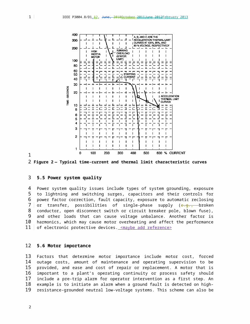
IEEE P3004.8/D1.12, June, 2010October 2011June 2012February 2013
6.4 Overcurrent protection (Device 51, inverse time) (Device 50, instantaneous)
Overcurrent sensing is the most frequently used method to monitor and protect the many power circuits in a facility. If a short circuit occurs, the action must be initiated without delay, whereas an overload within the service factor rating may not require any action. Under Chapter 15 guidelines, no delay should occur in the operation of the protection for circuit components (e.g., motors) upon sensing a fault, with backup protection coordinated by being delayed in time or overcurrent magnitude, or both.
Motor branch circuit protection is to operate whenever a motor fails to accelerate, when the motor-running current exceeds normal limits, and when a short circuit is detected. Time-overcurrent devices are normally used to protect against overloads and failure to accelerate, whereas instantaneous devices operate without any intentional delay for short-circuit protection.
Depending upon the motor rating and voltage, the devices for performing these functions are of different construction. For medium-voltage or large motors, the protection may be in the form of three phase-overcurrent protective relays or one multifunction relay (Device 11), which would include such other protective functions as accelerating characteristics, current unbalance, differential overcurrent, ground-fault current, and loss of load. Such complex protection would normally not be provided for unimportant low-voltage motors, although capable multifunction devices are available for low-voltage motor protection. In addition, some motors may be supplied directly from low-voltage switchgear and use the protective characteristics described in IEEE Std C37.17-1997 and shown in Chapter 7. The decision on whether to use low-voltage switchgear is usually influenced by the frequency of motor starts because motor controllers are rated for a considerably greater number of operations.
6.5 Multifunction relay (Device 11)
An important development has been the multifunction motor protection relay. Recognized as a powerful tool, the multifunction relay incorporates many protective functions that would normally be applied through the use of individual protective relays, but are all incorporated into one enclosure. For example, the relay incorporates short-circuit and overcurrent protection in each phase- and ground-fault protection. Depending upon the options selected, the relay could include protection against stalls, locked rotor, over-temperature alarm or trip, current unbalance, metering, and communications. No detailed discussion of the relay is included in this subclause because the possible functions are described under other protective relays, such as Device 50 and Device 51.
6.5.1 Medium-voltage multifunction relay applications <David Bredhold, lead; Ashvin Bapat; Pero Ostojic; Tim O’Hearn; Dan Ransom
Medium-voltage motor starters consist of a vacuum contactor protected by an intelligent relay. While a bimetallic thermal overload relay could be used, as is done for low-voltage motors, a greater measure of protection is usually desired for medium-voltage motors due to their cost and critical role in many applications. <expand fuses>
For some users, a medium-voltage circuit breaker is the preferred device for starting and stopping motors. As with a medium-voltage starter, a medium-voltage circuit breaker consist of a contactor (vacuum, SF6, or oil-filled) protected by an intelligent relay. <expand discussion of breakers vs. contactors; frequent starts>
<is contactors vs. breakers a topic of coverage for “protection”; device used for both types of switching; contactor rating is lower interrupt rating than breaker, transfer trip, ><Dan Neeser, consider moving first 3 paragraphs to section 8.1>
1
1
23456
789
10
11121314151617181920
21
2223242526272829
3031
32333435
363738
394041
2

IEEE P3004.8/D1.12, June, 2010October 2011June 2012February 2013
Formerly, individual devices may have been used for various protective functions. Several of them are noted earlier in this document: Instantaneous Device 50, Overload Device 51, Time Delay Device 62. While offering adequate protection, those devices occupied significant space, required significant labor to mount and wire, and required individual calibration and maintenance. Whether medium-voltage starters or medium-voltage breakers are used for motor starting, the same multifunction relay may often be used with either device to effect motor protection.
Modern multifunction relays offer protective and monitoring features impossible in older electro-mechanical devices. Waveform capture, starts-per-hour protection, fault data logs, broken rotor-bar detection, trending, motor load profiling are some of the diagnostic and monitoring functions available. <add thermal capability discussion; discuss frequent starts>
Multifunction relays usually provide operator interface panels, consisting of touch-screens or soft function keys with LCD screens, used for setup and for scrolling among the parameters. Many multifunction relays offer programming software. By using software a user can program the setup from a computer, upload new setups, download and save files, and monitor the relay locally. Some also have logic capability (AND, OR, NAND, NOR gates) programmable via the software.
Additional input/output capacity may be standard or optional for starter auxiliaries. Motor and bearing RTD inputs, formerly requiring a separate relay, may be available. <elaborate about functions>
<Dan Ransom, paper, photo, description – will check for release for use by this standard>
<photos – Eaton, David Bredhold; modern; other companies>
<add Multi-function definition – (device 11); include list of features & device numbers;>< IAS magazine has motor protection, page 10 History, Nov 2012>
Many users wish to have communications capability incorporated into protective relays. Communications-capabilities allow interfacing with the software package for setup, troubleshooting, and monitoring. Communications also allow remote monitoring of motors for operating status, operating current, fault history, and others. Older separate relays did not generally include communications. Communications may be accomplished via RS-232 or USB or fiber ports or RS-485. Protocols may be Modbus RTU, Modbus TCP, IEC-61850, and others. <discuss capabilities may vary with the type of protocol; expand protocols or get permission to use “trademark” names> .<add wired & fiber; industrial wireless>
<consider reference to drive section>
[this new section needs to include current application technology for protection and communications]
6.5.2 Low-voltage multifunction relay applications<David Bredhold, lead; Ashvin Bapat; Pero Ostojic; Tim O’Hearn; Dan Ransom
<consider smart starters, smart overloads, solid state devices>
<consider reference to drive section; consider drive as protection>
While protection for low-voltage motors was traditionally provided through use of heaters in bimetallic overload relays or from later solid-state overload relays, many users now desire greater protection. Multifunction relays are now offered for that purpose.
In addition to overload protection, multifunction relays are available for low-current (or low-power) protection for pumps to prevent cavitation, jam and stall protection, frequency-of-start, ground fault protection, and others. Arc flash sensing is now being incorporated into some multifunction relays.
1
123456
789
10
1112131415
1617
18
19
2021
22232425262728
29
30
3132
33
34
353637
383940
2

IEEE P3004.8/D1.12, June, 2010October 2011June 2012February 2013
Multifunction relays typically provide an human-machine interface (HMI) panel through which setup and monitoring may be accomplished. Fault-type, cause of fault, run/stop status, running Amperes, and other parameters may be read from the display. Remote HMI ports may be offered for mounting in motor control centers and enclosed starter enclosures.
Multifunction relays may also include as standard or optionally RTD inputs and additional input/output points. Input/output points may be used to interface with external control, reversing, multi-speed, and reduced-voltage starting systems.
Communications is now desired by some users. Where traditional overload relays have not included communications, many multifunction relays either include communications in the standard feature-set or offer it optionally. Communications available include RS-232, RS-485, Modbus RTU, Modbus TCP, IEC-61850, a Ethernet, and others.<add wired & fiber; industrial wireless>
[this new section needs to include current application technology for protection and communications]
6.6 Ground Fault Relay (Device 64)
This is a classic relay for ground fault detection. It is typically used for medium voltage motors, large motors > 750 kW or motors with a neutral. Various methods of ground protection are available such as ground sensing, zero sequence sensing and residual sensing.
6.7 Underexcitation (loss of field) Protection (Device 40)
This type of protection is only applicable to synchronous motors. It is applied to the rotor field winding.
6.8 Over Excitation (volts/hertz) Protection (Device 24)
This type of protection is only applicable to synchronous motors. It is applied to the rotor field winding.
6.9 Bearing Protection Relay (Device 38)
This relay monitors the bearing temperature and trips the motor when the operating temperature reaches the trip setpoint.
6.10 Mechanical Condition Protection Relay (Device 39)
This protection relates to occurrence of abnormal mechanical condition such as vibration, eccentricity, expansion, shock, tilting or seal failure. It uses various sensor to send signals to protection relays.
7. Low-voltage motor protection
<Dan Neeser, Lead; Al Wolf, David Bredhold, Ed Larsen, Ashvin Bapat.>
<Expand discussion of figures a, b, c, d; add figures that show CT protection; >
Conventionally, low-voltage motors drive small process equipment and auxiliary equipment. These motors, usually 220 kW and below, may operate continuously or may be in cyclical services. These applications
1
1234
567
89
1011
12
13
141516
171819202122232425262728293031323334
35
36
37
3839
4041
2
Jim Bryan, 02/01/13,
Grammar edits

IEEE P3004.8/D1.12, June, 2010October 2011June 2012February 2013
use motor contactors in motor control centers (MCCs) or combination starters. <align low-voltage motor sizes with 4.1 or delete>
One-line diagrams of typical low-voltage starters for industrial applications using MCCs or combination starters are shown in View (a), View (b), View (c), and View (d) and View (e) of Figure 3.
(e)
a) Typical starter with fuses b) Typical starter with a circuit breaker
c) Typical location for power factor correction capacitors d) Typical location for control power transformer
e) Typical starter with molded-case switch and fuses
Figure 3— Typical low-voltage starter one-line diagrams for industrialapplications using MCCs or combination starters
7.1 Low-voltage motor overcurrent protection
Overload protection for low-voltage motors is usually provided by thermal overcurrent relays or electronic overcurrent devices. In some cases, dual-element fuses or a thermal-magnetic circuit breaker may serve as the primary overload devices, but are normally backup protection for overload relays. Short-circuit protection for low-voltage motors is usually provided by fuses, a thermal-magnetic circuit breaker, or an instantaneous trip device (or motor circuit protection) in combination with an overload relay. Ground-fault protection for low-voltage motors is usually provided by the short-circuit protection device, but ground-fault relays may be installed. (See Bradfield and Heath [B1]; Nailen [B8]; Gregory and Padden [B4] and [B3]; Smith [B12].)
M
1
12
34
5
6
7
8
9
1011
12
1314151617181920
2
Jim Bryan, 02/01/13,
Do we really use fuses and breakers?

IEEE P3004.8/D1.12, June, 2010October 2011June 2012February 2013
7.1.1 Thermal and electronic overload relays
Thermal overload relays are constructed as either melting alloy or bimetallic. Although single-phase elements are the most common, they are also furnished in a three-phase construction block design. The relays are designed to operate within a current range, as follows:
a) Selection of the heater element should be based upon the relay manufacturer’s tables relating motor characteristics and ambient temperature conditions and based on the location of the motor relative to the relay. This method is employed because only minor adjustments need be made in the relay itself to set a trip value to match the motor current.
b) After the selection of the heater, the melting alloy unit is considered nontamperable.
c) Older bimetallic types may have limited adjustment of trip setting intended to compensate for ambient temperature. Newer relays have a wider range of adjustment.
d) The thermal memory of bimetallic overload relays provides satisfactory protection for cyclic overloading and closely repeated motor starts.
e) A manual reset feature is available and is normally trip free (i.e., manual override is not possible).
f) Some relays are available as ambient-temperature-compensated or as noncompensated. Noncompensated is an advantage when the relay and motor are in the same ambient because the relay opening time changes with temperature in a similar manner as the motor overload capability changes with temperature.
g) NEMA ICS 2-2000 has standardized motor overload relays into three classes denoting time delaydelay to trip on locked-rotor current: Class 10 for fast trip, 10 s at six times the overload rating; Class 20, for intermediate trip, for 20 s at six times the overload rating; and Class 30 for long-time trip, 30 s at six times the overload rating. In most applications, the Class 10 relay is applied for hermetic and other motors with a service factor of 1.00 or 1.05. The Class 20 relay is commonly used for higher service factor motors, such as NEMA Design T frame motors. A Class 30 relay is used in applications where high-inertia loads cause the motor to have a long starting time, such as conveyor belt motors. Electronic devices, sometimes integral with the contactor, sense the current in all three phases. They can be adjusted for Class 10, Class 20, or Class 30.
Overload relays are sized in accordance with the National Electrical Code® (NEC®) (NFPA 70-19992011). Article 430-32, Article 430-33, and Article 430-34 reference the motor nameplate rating. Power factor correction capacitors installed for individual motors may be connected as shown in View (c) of Figure 3, and no current adjustment need be made to the overload devices. However, this connection is not the only method of providing individual power factor correction and has been known to cause contactor failures due to resonance with other motor capacitors (see Nailen [B8]). When capacitors are installed between the overload device and the motor, the overload relay provides circuit impedance, which generally dampens the resonance problem. However, the overload relay current rating should be adjusted to account for the reduced current flowing to the motor-capacitor combination. Part 14.43.3 of NEMA MG 1-1998 recommends a bus connection when several motors are connected to the bus in order to minimize the potential harmonic resonance.
Overload relays and other devices for motor overload protection that are not capable of opening short circuits shall be protected by fuses or circuit breakers with ratings or settings in accordance with NEC Article 430-52 or by a motor short-circuit protector in accordance with NEC Article 430-52.
1
1
234
5678
9
1011
1213
1415
16171819
202122232425262728
293031323334353637383940
414243
2

IEEE P3004.8/D1.12, June, 2010October 2011June 2012February 2013
7.1.2 Time-delay (or dual-element) fuses
Time-delay fuses are available from 0.1 A through 600 A. Fuses for short-circuit and ground-fault protection shall be sized in accordance with NEC Article 430-52 and Table 430-152. The full-load current values used for that table are in Table 430-148, Table 430-149, and Table 430-150. The rating of a time-delay fuse shall be permitted to be increased, but in no case exceed 225% percent (400% percent for Class CC fuses) of full-load current. A one-line diagram of a typical starter with fuses is shown in View (a) of Figure 3. Also available are fuses without time delaydelay, which can provide short-circuit and ground-fault protection, but may not provide any backup protection.
7.1.3 Inverse-time circuit breakers
These circuit breakers (i.e., molded case) are available from 10 A through 3000 A when constructed with thermal-magnetic trip elements, and up to 5000 A when constructed with solid state trip elements. Both types of trip devices are referred to in the NEC as inverse-time circuit breakers and shall be sized in accordance with NEC Article 430-52 and Table 430-152. The full-load current values used for that table are in Table 430-148, Table 430-149, and Table 430-150. The rating of an inverse-time circuit breaker shall be permitted to be increased, but in no case exceed,
400% percent for full-load currents of 100 A or less,
300% percent for full-load currents greater than 100 A.
A one-line diagram of a typical starter with a circuit breaker is shown in View (b) of Figure 3.
7.1.4 Instantaneous trip circuit breakers (or motor circuit protectors)
<some breakers on the market with delay trip for ½ cycle; electronic time delaydelay may be available>
Instantaneous trip circuit breakers (i.e., molded-case), commonly called motor circuit protectors, are available from 3 A through 1200 A. The instantaneous setting can typically be adjusted in fixed steps to between 3 to 13 or 3 to 10 times the continuous-current rating. Instantaneous trip circuit breakers are tested under UL 489 [B13]. The trip range of the breaker should be within +30% percent or –20% percent of the set point. On the coordination plot, these devices have a broad bandwidth corresponding to these tolerances.
These breakers are referenced as instantaneous trip breakers and shall be sized in accordance with NEC Article 430-52 and Table 430-152. The full-load current values used for that table are in Table 430-148, Table 430-149, and Table 430-150. Trip settings above 800% percent for other than Design E motors and above 1100% percent for Design E motors shall be permitted where the need has been demonstrated by engineering evaluation. In such cases, it shall not be necessary to first apply an instantaneous trip circuit breaker at 800% percent or 1100% percent. Either an adjustable instantaneous trip circuit breaker or a motor short-circuit protector shall be used when it is part of a listed combination controller having coordinated motor overload, short-circuit, and ground-fault protection in each conductor and if it operates at not more than 1300% percent of full-load motor current for other than NEMA Design E motors and no more than 1700% percent of motor full-load current for Design E motors. A one-line diagram of a typical starter with a circuit breaker is shown in View (b) of Figure 3.<update the NEC references, to current Code>
Two points should be reviewed by the engineer. First, the overload device is normally the only line of protection from overloads and high-impedance faults when using instantaneous trip circuit breakers. A failure of the overload device, the overload wiring, or the contactor can prevent the circuit from being
1
1
2345678
9
101112131415
16
17
1819
20
21
222324252627
282930313233343536373839
404142
2

IEEE P3004.8/D1.12, June, 2010October 2011June 2012February 2013
isolated due to overload or high-impedance fault conditions. Where backup protection is desired for these abnormal conditions, an inverse-time circuit breaker or dual-element fuses should be selected.
Second, the selection of the contactor and conductor sizes depends on the setting of the instantaneous trip function. NEMA-rated magnetic contactors are tested to break up to 10 times the full-load current values given in NEC Table 430-148, Table 430-149, and Table 430-150 for the corresponding horsepower rating of the contactor. When an overload device trips, the contactor is called upon to open the circuit. Therefore, the contactor should be rated to break the circuit. Under high-impedance fault conditions, the current may be in the range of 10 to 17 times the motor full-load current. The instantaneous trip breaker may be set above the 10 times full-load current break test value of the contactor. Refer to Figure 4 for the time-current curves of a 480 V, 75 kW motor application with a 175 A instantaneous trip breaker, a Class 20 overload, and a NEMA size 4 magnetic contactor (i.e., 1350 A break rating). This figure illustrates a case where the instantaneous trip is set about 12 times the full-load current of 124 A (see NEC Table 430-150). The #2/0 AWG XHHW conductor is rated for 175 A at 75 C. The contactor is not protected using the setting of about 1500 A. A lower instantaneous setting would protect the contactor, but some motors may trip the breaker on starting. Contactors for NEMA Design E motors shall have a horsepower rating not less than 1.4 times the rating of a motor rated 3 kW through 75 kW, have a rating not less than 1.3 times the rating of the motor rated over 75 kW, or be marked for use with a Design E motor (see NEC Article 430-83, Exception No. 1).
Figure 4— Time-current curve for a 480 V, 75 kW motor with size 4contactor, Class 20 overloads, and an instantaneous trip circuit breaker with
a setting of 12 times full-load current
In a recently published book, the authors reveal that some high-efficiency motors draw up to 2.83 times locked-rotor current during starting, and they recommended a 19.2 times full-load current on the instantaneous breaker setting, approximately 3 times locked-rotor current in one case (see Prabhakara, et al.
1
12
3456789
101112131415161718
19202122
23
242526
2

IEEE P3004.8/D1.12, June, 2010October 2011June 2012February 2013
[B11]). A typical value used in the industrial applications is 1.76 times locked-rotor current for estimating asymmetrical inrush current. To prevent false tripping of the instantaneous trip breaker on starting, several options are available:
a) Use an autotransformer or other means for reduced voltage starting to limit the inrush current.
b) Specify a contactor with a higher break rating and set the instantaneous breaker at a higher setting within the NEC limits.
c) Use an inverse-time circuit breaker in place of the instantaneous trip breaker so that the instantaneous setting, if available, can be set above the motor inrush current.
7.2 Low-voltage motor ground-fault protection
Many low-voltage motor applications utilize fuses or MCCBs for ground-fault protection. However, the type of protection selected is dependent upon the type of system grounding.
7.2.1 Solidly grounded systems
Fuses and circuit breakers normally provide adequate ground-fault protection for motors on solidly grounded systems. However, for larger motors applications, such as the 75 kW motor shown in Figure 4, miscoordination occurs. For example, this motor is protected by an instantaneous only circuit breaker set at 1500 A trip. The main breaker ground trip is set at 1200 A, the maximum allowed by NEC Article 230-95, where a shutdown does not introduce additional hazards. Miscoordination can occur in the region between the ground trip device on the main low-voltage power circuit breaker (LVPCB) and the instantaneous trip circuit breaker protecting the motor. LVPCBs, specified with long-time and short-time functions only ( i.e., no instantaneous element), can usually be coordinated selectively. <add figure for this miscoordination, Dan Neeser resource>
If selectivity between the individual motor protective device and the main breaker is desired for ground faults, additional protective devices should be installed for the larger motors or interlocking ground-fault devices should be installed. For solidly grounded systems, the protective devices should be wired to open the breaker, not the contactor, unless the contactors are rated high enough to interrupt the available fault current. Some breakers have integral solid-state devices that sense ground faults and open the breaker. Contactors may also have integral solid-state devices that sense ground faults, but these may open the contactor. Also, zero-sequence current transformers (CTs) and trip units can be installed to shunt-trip the circuit breakers or switch, provided that the circuit breaker or switch has a shunt trip, which is not necessarily included on the circuit breaker or switch unless ordered that way.
7.2.2 Low-resistance-grounded systems
Low-resistance-grounded systems are not normally used on low-voltage applications. For low-resistance-grounded systems (e.g., between 200 A to 400 A), ground-fault currents may not be high enough to trip the MCCBs or to open fuses in a timely fashion, particularly for larger motors. <maybe reword or clarify why not>
1
123
45
67
89
10
11
1213
14
151617181920212223
242526272829303132
33
34
35363738
2

IEEE P3004.8/D1.12, June, 2010October 2011June 2012February 2013
7.2.3 High-resistance-grounded systems
For high-resistance-grounded systems, where the fault current is usually 5 A to 10 A range, no individual motor ground-fault protection is generally provided. Instead, an alarm at the grounding resistor signals that a ground fault has occurred. A ground pulsed signal is used to locate the fault. The faulted circuit is then manually cleared. Caution should be used when selecting conductor insulation materials and ratings for use on high-resistance-grounded systems, particularly on smaller conductors (e.g., size 10 AWG and below). Zone selective interlock (ZSI) tripping is another type of ground-fault protection that permits the first ground fault to be alarmed only, with rapid tripping following a ground fault on a different phase. This trip rating illustrates the advantage of high-resistance grounding when operation may continue during the presence of the first ground fault. Removal of the first ground fault is important, however, in order to prevent escalated damage from a second ground fault on a different phase. The MCCBs used in high-resistance-grounded systems should be rated for line-to-line voltage (e.g., 480 V not 480/277 V for a 480 nominal system voltage). (Also the single-pole interrupting rating should be checked to clear the second fault on a different phase: ground as well as line-to-ground faults on two separate phases, one on each side of the breaker. See Gregory [B2].) <clarify or delete ZSI discussion. See if there is a reference for smaller cables having problems high resistance grounded systems/ratings. ><Sensitive ground fault protection may be included in multifunction devices>
7.3 Low-voltage motor stator winding over temperature
The purpose of stator winding over-temperature protection is to detect excessive stator winding temperature prior to the occurrence of motor damage. In low-voltage motors in non-critical services, the temperature sensors are normally wired to trip the motor control circuit and open the contactor. . <consider philosophy to move from 7.3.3 to here>
7.3.1 Thermostat winding over-temperature devices
Thermostats are the most common type of stator temperature sensors installed in three-phase industrial service 460 V motors from 11 kW through 150 kW. Many manufacturers wind the stators with the devices installed and cut off the leads if a customer does not specify the protection. Thermostat devices are bimetallic, normally closed devices (or normally open devices) that operate at one fixed temperature. They are normally wired in series with the control circuit at 120 V. These devices are normally sealed from the atmosphere, but are not rated as hermetically sealed for hazardous NEC Class 1 Division 2 areas.
7.3.2 Thermistor winding over-temperature devices
Thermistors are used to operate relays for either alarm or trip functions, or both. They have resistance characteristics that are nonlinear with respect to temperature and thus are not used to indicate temperature. Two types of thermistors exist: <thermistor must match the control device>
d) Positive temperature coefficient. The resistance of a positive temperature coefficient thermistor increases with temperature. An open circuit in this thermistor appears as a high-temperature condition and operates the relay. This arrangement is fail-safe.
e) Negative temperature coefficient. The resistance of a negative temperature coefficient thermistor decreases as temperature increases. An open circuit in this thermistor appears as a low-temperature condition and does not cause relay operation.
1
1
23456789
1011121314151617
18
19202122
23
242526272829
30
313233
343536
373839
40
2
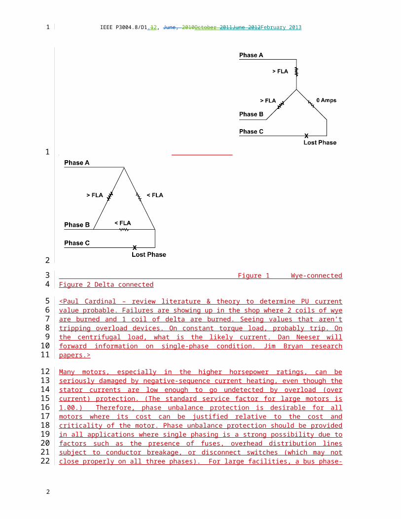
IEEE P3004.8/D1.12, June, 2010October 2011June 2012February 2013
7.3.3 Resistance temperature detector (RTD) winding over-temperature devices
RTDs may be considered in larger or critical service low-voltage motors. In those cases, the RTDs are usually connected into a device that provides an alarm and/or trip functions. The most common practice is to install six RTDs, two per phase, of the 100 Ω platinum elements class B to IEC 60751 for small motors and 100Ω platinum element class A to IEC 60751 for large or important motor. More information on RTDs is contained in 10.5.3.1.1. <may not refer to IEC, consider references to NEC>
RTDs are not normally installed in low-voltage motors unless the service is critical. In those cases, the RTDs are usually connected into a device that provides an alarm-only function. The most common practice is to install six RTDs, two per phase, of the 120 100 Ω platinum elements. More information on RTDs is contained in 10.5.3.1.1.
Low-voltage motor undervoltage protection
Undervoltage protection is used to protect motors from several damaging conditions: low voltage due to a voltage sag, automatic reclosing or automatic transfer, and power restoration. In a voltage sag, the motor draws more current than normal and has unusually high heating. Excessive heating can be a serious problem in hazardous areas where the motor must stay within its T marking.
When the supply voltage is switched off during automatic reclosing and transfers, the motors initially continue to rotate and retain an internal voltage. This voltage decays with motor speed and internal flux. If the system voltage is restored out of phase with a significant motor internal voltage, high inrush can occur. Such current can damage the motor windings or produce torques damaging to the shaft, foundation, drive coupling, or gears. IEEE Std C37.96-2000 discusses considerations for the probability of damage occurring for various motor and system parameters.
When power is restored after an outage, the starting sequence should be programmed so that all motors on the system are not starting simultaneously. This step is important for the generating equipment, as well as for transformers and conductors. Undervoltage devices are not normally installed on essential loads such as motors for fire pumps.
7.3.4 Undervoltage relays
Low-voltage undervoltage relays are typically electronic devices that monitor all three phases. These devices can be furnished with a time delaydelay to trip, a time delaydelay to restart, or instantaneous for trip and restart. Usually, the designer sets the device at 85% percent of line voltage with a time delaydelay off and a time delaydelay for restart. Normally, the undervoltage relays are wired into the motor control circuit to open the contactor.
7.3.5 Undervoltage sensors for circuit breakers
Some MCCBs have an undervoltage sensor adapter that trips the circuit breaker on a low-voltage condition. The circuit breakers are reset manually. Where automatic restart is necessary, this method should not be used. These sensors may not be as reliable as separate undervoltage relays, and this factor should be considered when designing the circuit.
8. Medium-voltage motor protection
< Dan Ransom lead, Jeff Hensley, David Bredhold, Ted Kloba>
1
1
23456
789
10
11
12131415
161718192021
22232425
26
2728293031
32
33343536
37
38
2
Jim Bryan, 02/01/13,
This is not clear?? What is the point?

IEEE P3004.8/D1.12, June, 2010October 2011June 2012February 2013
<add figures showing Mmedium- voltage 3-lines/1-lines>
< lead, >
Conventionally, large motors drive the main process equipment and would operate continuously for the length of the batch process. However, to accomodateBecause of this infrequentstopping and starting, medium-voltage circuit breakers are often used to apply the power to the motors. Medium-voltage motor voltage ratings are 2300 V, 4000 V, 4600 V, 6600 V, and 13 200 V per Part 20.12 of NEMA MG 1-1998. When a motor must be started frequently, it may might be necessary (even economical) to use motor contactors in a combination controller with a current-limiting fuse or circuit breaker because of the greater life of the contactors. Use cCare should be exercised when applying fused contactors on solidly grounded neutral systems because the contactor is incapable of interrupting high fault currents, especially ground faults. As a result, ground-fault relays and differential relays maymight not be applied safely applied. The risks could be minimized by having the manufacturer perform short-circuit tests on the combination controller to confirm its safe performance to in interrupting the fault on the system to which it is applied. In tThis subclause, the text refers to the usinge of circuit breakers for the main device to both close and open the motor circuit. The Ttext describing combination controllers for medium-voltage motors is generally similar to low-voltage combination controllers discussed previously.
In principle, the protection of medium-voltage motors is similar to low-voltage motors, but the requirements are more demanding. Being closer to the utility source, medium-voltage motors are more susceptible to voltage sags and surges, reclosing, and higher available fault levels. Because of the higher bus voltage and load currents, instrument transformers are used to reduce these currents to lower values, which can be used with protective relays, described in Chapter 4. The most common instrument transformer secondary ratings are 120 V (line-to-line) for voltage transformers (VTs), and 5 A for CTs, described in Chapter 3. The circuit breakers [i.e., air, sulfur hexafluoride (SF6), vacuum], instrument transformers, and protective relays are mounted in switchgear.
8.1 Medium-voltage motor thermal overload protection
Motors and synchronous machines develop heat while running. Monitoring heating, air and water flow, ambient air conditions, temporary overloads, intake air plenum damper positions is important. Also using an accurate model of the motor heating (using equivalent motor current) yields benefits in using the motor to maximum effect without damage.
Thermal protection of a motor is vital to motor longevity. Older motor protection methods used overcurrent 50 and 51 elements instead of the 49 thermal model (Device 49TC) and had no backup resistance temperature detector (RTD) temperature devices (49). Comparing these two methods of motor protection (Device 50/51 and Device 49TC), demonstrates the benefits of the Device 49TC thermal model for motor protection versus using an overcurrent method. Note that compromises must be made when employing overcurrent protection because typical 50/51 element curves do not match motor damage curves and do not take negative-sequence current effects into account.
A motor thermal model uses an “equivalent current,” Ieq, calculation that best represents the actual motor flux dynamics. This equivalent motor current accounts for the heating effects of negative-sequence and other currents present in induction motor applications.
The result of using thermal overload protection is extended motor life, and more efficient usage of motor capabilities. Figure 5 shows a set of typical motor operational curves for starting (accelerating) and for running (see IEEE Guide for the Presentation of Thermal Limit Curves for Squirrel Cage Induction Machines, IEEE Standard 620-1996, for an explanation of the construction of this chart). With Device 49TC protection, an engineer can place the motor-protection curve directly underneath the starting and running damage curves; replicating the exact shape of the damage curve without compromise and overlaps.
1
1
2
3456789
10111213141516
1718192021222324
25
26272829
30313233343536
373839
404142434445
2

IEEE P3004.8/D1.12, June, 2010October 2011June 2012February 2013
Thermal overload protection using the Device 49TC element is a better method for protecting medium-voltage motors than is simple overcurrent protection.
Figure 5 – Typical Motor CurvesHigh-inertia motors take a much longer time to accelerate, and without proper protection, this long acceleration time could lead to nuisance tripping. In addition, a low-voltage condition can also lead to a longer accelerating time, thus requiring careful selection of the type of protection relays and settings. A good practice for these motors is to request motor acceleration curves that are plotted for the cases of 100 percent and 80 percent of actual motor-starting voltage. At section 8.2.1, other techniques are shown on methods for high-inertia protection. In some cases, protective relaying might not adequately solve the problem, and a turning gear motor has been applied to start the large inertia motor in at least one case. This latter concept is expensive and is not a recommendation.
High-inertia motors (pumps and large fans) require modifications of the thermal overload protection curve. Newer motor protection relays offer this capability. An engineer can configure the overload protection curve to include extended starting times and currents, thus preventing false trips upon starting these devices.
8.2 Medium-voltage motor overcurrent protection
<Dan Neeser, add fused starter text and figures for motor protection, based on Buff Book Ch 6; coordinate with Carey Cook.>
In Figure 6 , Figure 7, and Figure 8, illustrate some additional techniques for illustrate differentother approaches applied forto large- motors protection. The accelerating curve has isbeen shown slightly
1
12
3
4
56789
101112
13141516
17
1819
2021
2
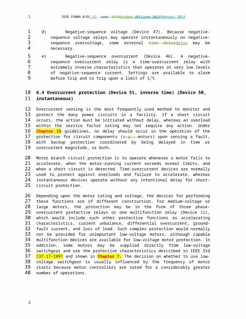
IEEE P3004.8/D1.12, June, 2010October 2011June 2012February 2013
differently in each case to demonstrate that no one single curve is accepted as a standard. T, and the motor accelerating curve should be provided by the motor or equipment supplier before setting the relays. High-inertia motors often take a much longer time to accelerate and, without proper protection, could lead to nuisance tripping. In addition, a low-voltage condition can also lead to a longer accelerating time, thus necessitating careful selection of the type of overcurrent relays and their settings. A good practice for these motors is to request motor acceleration curves that are plotted for the cases of 100% and 80% actual motor starting voltages. Under 10.58.2.1, some techniques are shown on how to resolve this protection. In some cases, relaying may not adequately solve the problem, and a turning gear motor has been applied to start the large inertia motor in at least one case. This latter concept is expensive and is not a recommendation.
In Figure 65, a NEMA Design- A or Design- B motor curve is shown with protection for starting and running easily made using a Device 51, a time-overcurrent relay element with inverse or very inverse characteristics. Within the overcurrent relay is a second element, a Device 50, which operates without delay to protect against a short circuit. Normally three overcurrent relays elements are used, each phase relayelement supplied from its owna separate CT. Some designers use only two of the three relays for overcurrent protection, and set Device 51 of the third relay relatively low (i.e., 110% percent to 120% percent of the full-load current) to alarm on an overload overcurent condition. Codes may not permit this practice in some cases, and redundancy is lost during relay testing. In this latter scheme, the two protective phase relays could be set for extreme overcurrent conditions at 125% percent to 140% percent of the full-load current.
Figure 6— Conventional overcurrent motor protection of motor
In Figure 67, protection for a high-inertiahigh-inertia motor allows for the longer accelerating time. Whereas Aa conventional motor reaches rated speed within 10 s to 15 s; , a high-inertiahigh-inertia motor maymight take 30 s to 40 sor longer (Ffor example, centrifuges maycan take about 40 minutes to reach rated speed; when starting wye/delta). As a result, little time difference exists between the accelerating current curve and the motor thermal limits. Several approaches are available, as shown in Figure 6 7 and Figure 78, and an impedance (Device 21) method is shown in Figure 8 9. In Figure 6 , Device 51 has long-time inverse or very- inverse characteristics, set above the accelerating current. (Definite- time delaydelay is another term to describe this element.) Device 50 (HDO) is a high- dropout (HDO) element that rapidly
1
123456789
10111213141516171819
2021
22
2324252627282930
2
IEEE P3004.8/D1.12, June, 2010October 2011June 2012February 2013
resets rapidly when the starting current drops to a magnitude of 85% percent to 90% percent of the set current without delay. For starting, a time delay of less than 1 s occurs is neededin order to permit the Device 50 (HDO) to be set atsetting at 1.15 p.u. of locked-rotor current (LRC or LRA). This delay prevents false trips due tocaused by the asymmetrical starting currents, yet provides short-circuit protection after the time delay. A second Device 50 element is set at approximately two times the locked-rotor current to protect against short circuits during starting.
Figure 7— Protection of high-inertia motor
Figure 7 illustrates a second method for protecting a high-inertia motor. This approach also uses two Device 50 elements per phase. The conventional Device 50 is set in the normal way to protect against short circuits. The second Device 50 is used in conjunction with the a Device 51 overcurrent element to block tripping by the Device 51 for overcurrent conditionss below the Device 50 setting. This scheme offers an overload overcurrent alarm, while allowing the motor to continue operating unless the actual overcurrent exceeds a high setting. The use of this scheme is dependent upon the operating philosophy of the facility. Large motors should be specified with thermistors or RTDs buried in their windings for high-temperature backup detection. Note that, although temperature changes are generally slower to develop than overcurrent and thermal overload increases. Actual faults within the windings would be detected faster by thermal overload (Device 49TC), overcurrent differential relay protection (Device 87), andor a sensitive ground-fault current (Device 51N) relay protection schemes.
1
123456
78
9
1011121314151617181920
2
IEEE P3004.8/D1.12, June, 2010October 2011June 2012February 2013
A — ALLOWABLE HEATING CURVE
B — STARTING CURRENT
C — 51 — LONG TIME OC
D — DEFINITE TIME SET 120% percent FL
E — INVERSE INST 50
Figure 8— Alternate method of protecting a high-inertia motor
Figure 8 9 represents shows a scheme that relies upon the characteristics of an Device 21 (i.e., impedance distance (Device 21) relay) to permit tripping if the high-inertia motor does not accelerate to a certain speed within a fixed period. Upon energization of the motor circuit energization, the locked-rotor current is primarily inductive, as because a blocked motor could easily be considered a transformer with shorted secondary windings. As the motor accelerates,, the current decreases from a subtransient to a transient value, and the power factor and measured impedance increase. Used in conjunctionAlso used with the Device 21 is are either an overcurrent relay (Device 51), or an overvoltage relay (Device 59) that, which operates as a timing device in this case. This scheme guards against a stalled motor. O although other schemes exist, such as zero-speed devices used with timers (Device 48). Figure 9 10 illustrates how the locked-rotor protection functions below the safe stall time.
1
1
23
4
5
6
7
8
9
10
11121314151617181920
2

IEEE P3004.8/D1.12, June, 2010October 2011June 2012February 2013
Figure 9— Protection of high-inertia motor using an impedance relay
Figure 10 — Schematic of locked-rotor protection of Figure 8
Device 21
1
12
3
45
6
2

IEEE P3004.8/D1.12, June, 2010October 2011June 2012February 2013
8.3 Fault protection
8.3.1 Motor overcurrent differential relay (Device 87)
Motor overcurrent differential protection measures the current flow into a load and compares it to the current measured on the neutral side of the motor; for normal operation the current going in and the current going out match and cancel. A current difference is detected as a fault. These schemes can be technically applied to any motor load, but often are applied only to large or critical motors only where damage could be costly or replacement difficult. By detecting faults at a low level, damage maycan be confined solely to the windings solely. Three general recommendations forGenerally, applyying differential overcurrent protection are as follows:
a) With all motors 750 kW (1000 hp) and above larger used on ungrounded systems.
b) With all motors 750 kW (1000 hp) and above larger used on grounded systems where the ground-fault protection applied is not considered sufficient without differential protection to protect against phase-to-phase faults.
c) With smaller motors, especially at voltages above larger than 2400 V
d) , although justifying differential protection for large motors (i.e., 1900 kW (2500 hp) and abovelarger); justification is easier.
8.3.1.1 Conventional phase differential overcurrent relay
A conventional phase- differential overcurrent relay is used to senses low-level phase faults and to quickly removes the motorelectric circuit power quickly before extensive motor damage develops. This scheme uses six identical CTs (i.e., one pair for each phase) and three relays (i.e., one per phase). The CTs should be sized to carry full-load current continuously and to not saturate during an external or internal fault (see Figure 10). The currents from each pair of CTs circulate through the relay-restraining windings under normal (i.e., no-fault) conditions. For a fault in the motor windings or in the cable, the CT secondary currents have different magnitudes and/or polarities, and the differential current from each CT adds to the other and operates the Device 87 to trip the motor circuit breaker. While sometimes applied toThis scheme is employed for both delta-connected motors, this scheme is usually used with and for wye-connected motors. (W. ye-connected motors are much more common than delta-connected ones in the larger horsepower ratings.) With the wye-connected motor, three of the CTs are normally located at the starter (or motor switchgear) and the other three in the three phases at the motor winding neutral.
1
1
2
3456789
10
111213
14
1516
17
18
192021222324252627282930
2
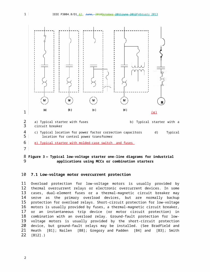
IEEE P3004.8/D1.12, June, 2010October 2011June 2012February 2013
Figure 11 — Conventional phase differential protection using three (3)percentage differential relays
8.3.1.2 Self-balancing differential using window CTs
Three window (or toroidal) CTs are normally installed at the motor. One CT per phase is used, with the motor line, and neutral leads of one phase are passed through the CTit so that the flux from the two currents normally cancels each other in the CT. A winding phase-to-phase or phase-to-ground fault results in an output from the CTs of the associated phases. That current operates the associated relays elements (see Figure 1112).
Figure 12 — Self-balancing differential protection (one relay element shown)
Normally in one relay package, The the Device 87 CTs and relayelements would normally be the same as the CTs and relays used for zero-sequence instantaneous ground overcurrent protection (see 10.5.2.3.2) with the relay set between 0.25 A and 1.0 A pickup. Therefore, this differential scheme usually has a lower primary pickup in amperes than the conventional differential scheme because the CT ratio is usually greater with the conventional scheme. This differential scheme has a slight advantage over the scheme in Figure 10 in detecting ground faults. For motors installed on grounded systems this difference is significant because most faults begin as ground faults. The usual objective of motor-fault protection is to remove the fault before the stator iron is significantly damaged significantly.
1
123
4
56789
1011
12
1314151617181920
2

IEEE P3004.8/D1.12, June, 2010October 2011June 2012February 2013
Application problems have occurred with this scheme when the available fault current is very high and when high-speed, balanced-core differential protection signals to tripping the motor starter before the current-limiting fuses clear the fault (and thus protecting the starter). Because the starter has such a low fault rating, some engineers have slowed down the operation of the relay, by delay or a different relay type, in order to distinguish between a developing low-level fault and a direct short.
With the CTs located at the motor, this scheme does not detect a fault in the cables supplying power to the motor. Normally, a fault in these cables would normally be detected by the overcurrent protection. For large motors, coordinating the supply phase-overcurrent protection with the motor thermal overcurrent overload and overcurrent protection is often a problem. The presence of motor differential protection is sometimes considered to make this coordination less essential. In this regard, the conventional current differential is better than the self-balancingself-balancing flux flux differential because the motor cables are also included in the differential protection zone. Hence coordination between the motor differential and supply phase-overcurrent relays is complete.
As with zero-sequence ground-fault overcurrent protection, testing the overall CT and relay combinations is important during commissioning. Current in a test conductor should be passed through the window of each CT. Because normally the relays do not carry current, an open circuit in a CT secondary or wiring to a relay can be discovered by this overall testing.
8.3.2 Split winding current unbalance (Device 87)
8.3.2.1 Purpose
The purpose of the split- winding current unbalance device is to quickly detect quickly a low-magnitude fault conditions. This protection also serves as backup to instantaneous phase-overcurrent and ground-fault overcurrent protection. Normally, tThis protection is normally only applied only to motors having two (or three) winding paths in parallel per phase (see Figure 12). <(Ddo not useconfuse this arrangement with partial- on part-winding starting, discussed elsewhere.) applications>
Figure 13 — Split-phase winding motor overcurrent protection used withtwo paths windings per phase (one relay shown)
1
12345
6789
10111213
14151617
18
19
2021222324
252627
2

IEEE P3004.8/D1.12, June, 2010October 2011June 2012February 2013
8.3.2.2 Arrangement of CTs and relays
<check for proper term, split winding or split phase>
The usual application is with a motor having two or more winding paths in parallel per phase. The six line leads (i.e., two per phase) of the motor are brought out, and one CT is connected in each of the six leads. Choose tThe primary current rating of the CTs should be chosen to carry full-load current (FLC or FLA).
The CTs may can be installed at the motor. It maymight be convenient, however, to use six cables to connect the motor to its the starter (or switchgear), and in this case the CTs can be located in the starter.
The currents from each pair of CTs, associated with the same phase, are subtracted, and their difference is fed to a short-time inverse-e time -overcurrent relay. Three of these relays are required (i.e., one per phase), and each is set at 1.0 time dial and between 0.5 A and 2.5 A. The relay should be set above the maximum current unbalance that can occur between the two parallel windings for any motor-loading condition.
8.3.2.3 Evaluation of split windingsplit-winding current unbalance protection
The following factors should be considered when evaluating split- winding current unbalance protection:
a) Total cost would be somewhat less than conventional phase current differential and more than self-balancingself-balancing flux differential.
b) The primary pickup current for this protection would be about half of the primary pickup current of conventional phase differential because both schemes require the CT primaries to be rated to carry normal load currents. Self-balancing differential would usually have a lower primary pickup (in amperes).
c) This protection has a slight time delaydelay compared to the phase current differential schemes.
d) When the CTs are located in the motor starter, split- winding protection has the same advantage over self-balancingself-balancing flux differential as does conventional phasecurrent differential, namely, it detects a fault in the motor cables and may facilitates coordination with the supply feeder overcurrent relays (see 10.5.2.1.2).
e) The salientA feature that of this protection provides, and no other motor protection has, is the ability to sense short-circuited winding turns. The number of turns that must be short-circuited before detection occurs depends upon the motor winding arrangement, the relay pickup, and CT ratio. An analysis of the specific motor winding would be required to determine the worthiness of this feature. Short-circuited turns could cause a ground fault, which could be detected by the self-balancingself-balancing flux differential scheme before this split- winding protection would sense the short-circuited turns condition.
f) This protection could be applied to a motor with four winding paths in parallel per phase by grouping them these as two pairs as if only two paths in parallel existed (i.e., six CTs and three relays are used).
g) Often, aA split differential scheme is can be often effective ly used where one CT is in one of the parallel paths and the other CT sees the total phase current.
8.3.2.4 Application of split- winding protection
Split winding protection is rarely used rarely, but is feasible to apply tofor important motors rated above greater than 3700 kW that have two or four winding paths in parallel per phase.
1
1
2
345
67
89
1011
12
13
1415
16171819
2021
22232425
26272829303132
333435
3637
38
39
4041
2

IEEE P3004.8/D1.12, June, 2010October 2011June 2012February 2013
8.3.3 Ground-fault protection
8.3.3.1 Purpose
The purpose of ground-fault protection is to protect motors by detecting ground-fault conditions with no intentional delay and to be certain that the unbalance current represents a true ground fault ( i.e., not current fromdue to asymmetry in the primary current, or and currents fromto CT saturation). Following this detectionUpon detecting a ground fault, the protection maymight trip the motor circuit or only alarm, depending upon the voltage and facility operating practice.
8.3.3.2 Instantaneous ground-fault protection
Using a zero-sequence (or window) flux CT that has been designed for instantaneous ground-fault protection and tested with a specific ground-fault relay is recommended (see Figure 1314). For medium-voltage applications, the power system should be resistance-groundedhigh-impedance grounded, or hybrid grounded. , and tThe Device 50G element should be set to operate for a primary ground-fault current in the range of 10 A to 30 A. A suitable time delaydelay should be added when the installation has surge protection on the motors.
Figure 14 — Ground fault overcurrent protection using a window (flux) CT
8.3.3.3 Time-overcurrent ground-fault protection
Many installations have surge protection at the motor terminals, and a surge discharge through an arrester could cause an instantaneous relay element to have a false trip. To avoid this event, a Device 51G should be applied, in place of the Device 50G in Figure 13, and set to trip within a few cycles to seconds of the fault-sensing pickup.
8.3.3.4 Installation of cable for ground-fault protection
The following precautions should be observed in applying the relay and zero-sequence CT and in installing the cables through the CT:
1
1
2
34567
8
91011121314
1516
17
18192021
22
2324
2

IEEE P3004.8/D1.12, June, 2010October 2011June 2012February 2013
h) If the cable passes through the CT window and terminates in a pothead on the source side of the CT, the pothead should be mounted on a bracket insulated from ground. Then the pothead should be grounded by passing a ground conductor through the CT window and connecting it to the pothead.
i) If metal-covered cable passes through the CT window, the metal covering should be kept on the source side of the CT, insulated from ground. The terminator for the metal covering maymight be grounded by passing a ground conductor through the CT window and then connecting it to the terminator.
j) Cable shields should be grounded by passing a ground conductor through the CT window and then connecting it to the shields.
k) The overall CT and ground relay scheme should be tested by passing current in a test conductor through the CT window. Because normally no current exists in the relay, an open circuit in the CT secondary or wiring to the relay can be discovered by this overall test.
8.3.3.5 Residually connected CTs and ground-fault relay
Applications have been made using the residual connection from three CTs (i.e., one per phase) to supply the relay. This arrangement is not ideal because high large phase currents (e.g., due tofrom motor starting inrush or phase faults) maymight cause unequal saturation of the CTs and produce a false residual current. As a result, undesired tripping of the ground relay maycan occur, and the production or process may could be jeopardized. For this reason, a Device 50N is not recommended in the residual connection. A Device 51N installed in the residual connection would be more appropriate for these installations.
<add figure like Figure 13 for zero sequence>
8.3.3.6 Selection of resistor for low-resistance system grounding
The purpose of resistance grounding is to provide current sufficient for protective relays to operate upon detection of a ground fault, but low sufficiently smallenough to limit the magnitude and resulting damage to the motor. (In mine distribution systems, the objective is to limit equipment-frame-to-earth voltages for safety reasons.) However, the ground-fault current should not be so limited small that the windings near the neutral end are unprotected. In the past, protection within 5% percent to 10% percent of the neutral has often been considered adequate. Selection of the ground resistor should also consider the number of steps in ground-fault overcurrent protection coordination (see Love [B5] and [B6]). On this basis, the ground resistor chosen for the system neutral grounding normally limits the ground-fault current within the range of 400 A to 2000 A. However, some companies prefer neutral ground-fault current limited to 200 A to 800 A; this difference emphasizes the need to coordinate the protection of a system. A 10- s time rating is usually chosen for the resistor.
To avoid excessive transient overvoltages, the resistor should be chosen so that the following zero-sequence impedance ratio is achieved:
R0 / X0 should be equal to or greater than 2.
A more detailed discussion of the selection of the resistor can be found in Chapter 8.
1
1234
5678
910
111213
14
15
161718192021
22
23
2425262728293031323334
3536
37
38
2

IEEE P3004.8/D1.12, June, 2010October 2011June 2012February 2013
8.4 Monitors
In addition to protection against failures due tocaused by electrical causesabnormalities, advances in instrumentation and techniques have enabled protective methods that monitor machinery characteristics and, as a result, can detect trends of equipment failures during the incipient stage. This development has manifested into monitors, sensors, and detectors that use inputs not related directly to measured electrical quantities of voltage and current.
8.4.1 Stator winding over temperature
The purpose of stator winding over-temperature protection is to detect excessive stator winding temperatures prior to the occurrence of motor damage. Often, tThis protection is often arranged just to alarm on motors operated with competent supervision. Sometimes two temperature settings are used, the lower setting for alarm, the higher setting to trip. The trip setting will depends on the type of winding insulation used for its winding and on the user operating requirements of the user.
8.4.2 RTDs
Six RTDs (two per phase) should be specified in motors rated 370 kW (500 hp) and above. These devicesy are installed in the winding slots when the motor is being wound. The six RTDs are spaced around the circumference of the motor core to monitor all phases. The most commonly used type is three-lead, 120 100- Ω platinum for Class B to IEC 60751 for small motors, and 10-0Ω platinum element Class A to IEC 60751 for large orand critical motors with three leads. A four- lead RTD is used shouldfor applications that require higher accuracy. The RTD element device resistance increases with temperature, and a Wheatstone bridge devices or similar circuitry isare used to provide temperature indication or and contact output operation, or both. . The value of the temperature trip will depends on the type of winding insulation used (see Table 1) and the operating requirements of the user.. <discuss this value>
<consider removing IEC, use NEC>
For safety, RTDs should be grounded, and that ground in turn places a ground on the Wheatstone bridge control module. Therefore, the Wheatstone bridge control module should not be operated directly from a switchgear dc battery because these dc control schemes should normally operate ungrounded in order to achieve maximum reliability. However, loss of ac control voltage due tocaused by a blown fuse could remove protection, unless the null point is near the trip setting at which time it could cause tripping.
An open RTD or its an open RTD circuit appears as an infinite resistance and causes a false trip because this corresponds to a very high temperature. Newer motor protection relays use RTD voting to prevent the threat of a false temperature reading (and subsequent false alarms and false tripping). To indicate an excess-temperature condition, the relay must receive sufficient high-temperature indications from multiple RTDs (the number of RTD votes is configurable). In this way damaged and open-circuit RTD inputs are ignored.
The following arrangements of RTDs are frequently used frequently:
a) Monitor all six leads continuously with alarm points and time-delayed, higher elevated trip points using one monitor or a programmable logic controller.
b) Monitor six leads with alarm points and have a manual trip.
1
1
23456
7
89
101112
13
14
151617181920212223
24
2526272829
303132333435
36
3738
39
2
Jim Bryan, 02/01/13,
The user may require a trip setting lower than the maximum allowed by the insulation class.

IEEE P3004.8/D1.12, June, 2010October 2011June 2012February 2013
c) Configure alarm points and trip points for selected sectors of the motor section. Determine which detector normally runs hottest and permanently connect a trip relay to it. Use one temperature indicator and a selector switch to manually monitor the other five detectors.
d) Use a selector switch and combination indicator and alarm relayelements. (Precaution: An open circuit in the switch contact will cause a false trip. Bridging contacts are required.)
e) Use a selector switch and an indicator only.
f) Use one, two, or three (i.e., one per phase) alarm relays; and use one, two, or three (i.e., one per phase) trip relays set at a higher temperature.
<discuss damaged RTDs, voting, >
8.4.2.1 Thermocouples
Thermocouples are used to indicate temperatures for alarm and trip functions, in a similar manner to RTDs. However, an open circuit in the thermocouple leads does not cause a trip because the output appears as a low-temperature condition. It is advisable to use thermocouple of Tolerance Class 1 for high accuracy in a large motor. ShouldIf the transmitter/transducer for the temperature is not head mounted or located < 0.5m from the thermocouple terminal lead, then it should be connected with a suitable thermocouple extension cable to the transmitter/transducer. For safety, similar to the As per RTDs, for safety the thermocouple must be ofhave a grounded junction. In usual caseUsually, the grounding of the thermocouple grounding is done on the sheath at the terminal box. Thermocouple outputs from thermocouples isare compatible with conventional temperature-monitoring and data-logging schemes, and newer relays have (4–20 mA and 0–10 V) analog inputs for inputting thermocouple data via the proper interface..
Limit or Errors ASTM E230- ANSI MC 96.1
Table 1 –Temperature classifications for wire insulation
1
123
45
6
78
9
10
11
12131415161718192021
2223
24
2
Jim Bryan, 02/01/13,
The grammar is not clear here but I do not get the point to try to correct it.
Jim Bryan, 02/01/13,
I disagree with this change, it should be restored to the original verbiage.

IEEE P3004.8/D1.12, June, 2010October 2011June 2012February 2013
8.4.2.2 Thermistors
Thermistors are used to operate relays for alarm or trip functions, or both. They These devices are not used to provide temperature indication. However, they thermistors are often combined with thermocouples, which provide indication, while the thermistor operates a relatively inexpensive relay. See 10.4.3.2 for further details.
8.4.2.3 Thermostats and temperature bulbs
Thermostats and temperature bulbs are used on some motors. For instance, thermostats are bimetallic elements and are used on random- wound motors (460- V class, not medium-voltage motors) to detect failure to start. They These are embedded in the end windings and provide a contact opening to trip the motor. Bulb temperature devices are used to provide measurement and trip contacts for bearing oil temperature in oil-lubricated bearings. See 10.4.3.1 for further details.
1
1
2345
6
789
1011
2
IEEE P3004.8/D1.12, June, 2010October 2011June 2012February 2013
8.4.2.4 Application of stator winding temperature protection
Stator winding temperature protection is commonly specified on for all motors rated 190 kW (250 hp) and abovegreater. RTDs are commonly specified in for all motors rated 370 kW (500 hp) and abovegreater. In the following situations, the application ofapplying stator winding temperature protection should be considered:
a) Motors in high ambient temperatures or at high altitudes
b) Motors whose with ventilation systems that tend to become dirty and lose cooling effectiveness
c) Motors subject to periodic overloading due tocaused by load characteristics of the drive or the process
d) Motors likely to be subjected to continuous overloading (within their service- factor range) in order to increase production
e) Motors for whichused in critical continuity of service applications is critical
f) Motors supplied from ASDs (adjustable speed drives)
g) Motors in hazardous (classified) locations
8.4.3 Rotor over temperature
8.4.3.1 Synchronous motors
<Dan Ransom; lead, Chris Heron. Update, operating outside the V-curve too long>
Rotor winding over-temperature protection is available for brush synchronous motors, but although, normally, this protection is not normally used. One well-known approach is to use a Kelvin bridge chart recorder with contacts adjustable to the temperature settings desired. The Kelvin bridge uses field voltage and field current (from a shunt) as inputs and measures the field resistance in order to determine the field winding temperature.
8.4.3.2 Wound-rotor induction motor-starting resistors
<Chris Heron. Update>
Some form of temperature protection should be applied for wound-rotor induction motor-starting resistors on motors having severe starting requirements, such as long acceleration intervals or frequent starting. RTDs and other types of temperature sensors have can been used, placed in proximity to the resistors.
1
1
2
3456
7
89
1011
1213
14
15
16
17
18
19
20
2122232425
26
27
282930
2
IEEE P3004.8/D1.12, June, 2010October 2011June 2012February 2013
8.4.4 Mechanical and other protection
8.4.4.1 Motor bearing and lubricating systems
Various types of temperature sensors are used on sleeve bearings to detect overheating: , such as RTDs, thermocouples, thermistors, thermostats, and temperature bulbs. Excessive bearing temperature maymight not be detected soon enoughin time to prevent bearing damage. More serious mechanical damage to the rotor and stator may can be prevented by tripping the motor before complete bearing failure. Thus, for maximum effectiveness, the following steps are recommended:
a) Use a fast-responding temperature sensor (not an RTD).
b) Locate the temperature sensor in contact with the bearing metal where it is close to the source of overheating.
c) Use the temperature sensor for tripping instead of alarm; for some installations, use both alarm and trip sensors, the former having a lower temperature setting.
d) Provide alarm and trip devices on bearing lubricating systems to monitor the following:
1) Lubricating oil temperature, preferably from each bearing
2) Bearing cooling water temperature, both temperature in and out
3) Bearing lubricating oil flow and cooling water flow
In lieu of the flow-monitoring recommended in Item d) 3), often a suitable arrangement of pressure switches is often used. However, flow monitoring is strongly recommended for important or high-speed machines.
Temperature sensors generally cannot detect impending failure of ball bearings andor roller bearings soon in timeenough to be effective. Vibration monitors and detectors should be considered (see 10.5.3.4).
Protection to that detects currents that maymight cause bearing damage should be considered for motors having insulated bearings. Recent research in vibration rotor-bar heating has discovered that these conditions exhibit discernible signatures (usually in the frequency domain). Specialized equipment detects this effect, and is used on large and critical-application motors. <clarify, Dan Ransom, Jim Bryan, provide references>
8.4.4.2 Ventilation and cooling systems
Alarm and trip devices should be considered, as follows:
a) In motor ventilation systems
1) To detect high differential pressure drop across air filters
2) To detect loss of air flow from external blowers (In lieu of air flow monitoring, a suitable arrangement of pressure switches is often used; however, flow monitoring is preferable.)
b) With water-cooled motors, to monitor water temperature, flow, or and pressure
c) With inert-gas-cooled motors, to sense pressure and temperature
d) For motors in hazardous areas, to detect flammable gasses and vapors gas
1
1
2
34567
8
910
1112
13
14
15
16
17181920
2122
2324252627
28
29
30
31
3233
34
35
36
37
2

IEEE P3004.8/D1.12, June, 2010October 2011June 2012February 2013
8.4.4.3 Liquid detectors
On large machines, liquid detectors are sometimes provided to detect liquid (usually water) inside the stator frame, e.g., because of a leak in the air cooler of a totally enclosed water- and air-cooled motor.
8.4.4.4 Fire detection and protection
For fire detection and protection, the following items should be considered:
a) Installation of suitable smoke and flame detectors to alert operators to use suitable portable fire extinguishers.
b) Installation of suitable smoke and flame detectors and an automatic system to apply carbon dioxide or other suppressant into the motor. Some old, large motors have internal piping to apply water for fire extinguishing. Possible false release of the water is a serious disadvantage.
c) Use of synthetic lubricating oil that does not burn, particularly for drives having large lubricating systems and reservoirs and for systems in hazardous atmospheres. Lubricating systems of gas compressors or hydrocarbon pumps should be kept separate from the motor to preclude combustibles and flammables from entering the motor through the oil system.
8.4.4.5 Partial discharge detectors
Partial discharge detectors are embedded in the windings. They These detectors show a pattern of frequencies that are normal for a motor. Abnormal patterns of corona indicate insulation damage. These detectors are normallyshould be considered for installed on large motors (>7500 kW) 4000 V and above, particularly used for motors in critical service.
[<Chris Heron, lead; expand this section, picture(s), releases]>
8.4.5 Vibration monitors and sensors
8.4.5.1 Purpose of vibration monitoring
[update this section, get copyright releases; add NEMA tables]
Vibration monitoring has advanced from an important startup function to an effective tool during operation of the process. It increases safety and reliability and maymight reduce costs over the life of the plant. The three components of a vibration monitoring system are transducers, monitors, and machine diagnostic equipment, although many installations maymight not have permanent monitors and diagnostic systems (see Figure 1415).
1
1
23
4
5
67
89
10
11121314
15
16
17181920
21
22
23
24
2526272829
2

IEEE P3004.8/D1.12, June, 2010October 2011June 2012February 2013
Figure 15 — Vibration monitoring system
8.4.5.2 Transducers
Transducers are a critical part of a vibration monitoring system. Accurate machinery diagnostics depend upon reliable transducer signals. Two orthogonal, or XY, transducers should be installed at or near each bearing; and a phase reference probe, such as a once-per-turn event probe, should be installed on each shaft. This configuration provides diagnostic equipment with the information necessary to accurately indicate accurately the vibratory motion. Transducers should be of rugged construction to better withstand the motor’s environment. In general, if rotor-related malfunctions are anticipated (e.g., unbalance, misalignment, rubbings), vibration transducers that observe the rotor should are be preferred. If housing-related malfunctions are anticipated (e.g., piping strains, structural resonances), transducers mounted on the machine housing should are be preferred.
8.4.5.3 Proximity transducers
On motors with fluid-film bearings, such as sleeve bearings, non-contacting proximity transducers (see Figure 1516) provide the best information data and should be preferredare preferred. Often on these motors, much of the rotor motion is not transmitted to the housing. Non-contacting proximity transducers accurately indicate accurately the displacement of the rotor displacement relative to the housing. They These transducers have a broad frequency response, down to dc (i.e., 0 Hz) at the low end. The upper- end frequency response is also high great (up to 10 kHz), but useful application at high frequencies is limited because little measurable displacement occurs at these high frequencies. This Proximity transducers can measure slow-roll and the shaft’s average position within the bearing. For motors with rolling-element bearings, a special transducer can be applied to provide an earlier warning of bearing malfunctions than provided by velocity transducers or accelerometers provide. Such motors have a high-gain, low-noise eddy-current proximity transducer that is installed in the bearing housing to observe the bearing outer race. Such These transducers maymight be difficult to install in motors with tight clearances. See Figure 16 17 for a vibration- limit curve.
1
12
3
456789
101112
13
14151617181920212223242526
2

IEEE P3004.8/D1.12, June, 2010October 2011June 2012February 2013
Figure 16 — Typical proximity transducers
Reprinted with permission API. . .
NOTES:
1) [INSERT]
2) [INSERT]
3) [INSERT]
Figure 17 — Shaft vibration limits (relative to bearing housing usingnon-contact vibration probes): for all hydrodynamic sleeve-bearing motors;
with the motor securely fastened to a massive foundation
1
12
3
45
6
7
8
9
101112
2
IEEE P3004.8/D1.12, June, 2010October 2011June 2012February 2013
8.4.5.3.1 Velocity transducers
Velocity transducers may can be used on motors with rolling-element bearings where virtually all of the shaft motion is faithfully transmitted to the bearing housing. Velocity transducers are seismic devices that measure motion relative to free space; these transducers, are useful for overall vibration measurement, and provide good frequency response in the mid-frequency range (i.e., 4.5 Hz to 1 kHz). This transducer is self-generating; no power source is required. Traditional velocity transducers are mechanical devices that suffer from a limited life span. Some modern velocity transducers use a piezoelectric sensing element; these tranducers, do not suffer fromhave a limited life span this limitation, and are thus preferred. See Figure 17 for a vibration- limit curve.
Reprinted with permission . . .
NOTES:
1) [INSERT]
2) [INSERT]
3) [INSERT]
Figure 18 — Bearing housing vibration limits: for sleeve and antifrictionbearing motors; with the motor securely fastened to a massive foundation
8.4.5.3.2 Accelerometers
Accelerometers are generally used on motors with rolling-element bearings where virtually all of the shaft motion is transmitted to the bearing housing. Accelerometers are useful for overall vibration measurements and have a broad frequency response. They These devices are particularly useful particularly for high-
1
1
23456789
1011
12
13
14
15
1617
18
19
202122
2

IEEE P3004.8/D1.12, June, 2010October 2011June 2012February 2013
frequency measurements. An accelerometer is almost the only viable transducer at high frequencies (usually above greater than 5 kHz). Motor vibration acceleration increases with frequency. Therefore, the acceleration unit of measurement is favoredpreferred. However, at low frequencies, its the accelerometer usefulness is limited. Accelerometers are sensitive to the method of attachment and the quality of the mounting surface.
8.4.5.3.3 Vibration limits
API Std 541-1995 recommends limits for shaft and bearing vibrations, using non-contact vibration probes on hydrodynamic bearing motors operating at speeds equal to or greater than 1200 r/min. Examples of these limits are shown in Figure 16 17 and Figure 17 18 from API Std 541-1995. <NEMA recommends limits…..section 7, Figure 7-5, >
8.4.5.4 Monitors
8.4.5.4.1 Monitors process and display transducer signals
Monitors should detect malfunctions in the transducer system and the transducer power supply. These devicesy should provide two levels of alarms, and protect against false alarms. They Monitors should be constructed so that both the unprocessed and processed information is available to online and portable diagnostic equipment. Monitors designed to work with accelerometers or velocity transducers should be able to integrate the signal. Modern motor relays have incorporated many of the monitoring functions. See Figure 198 for sample monitoring system panels.
Reprinted with permission . . .
1
12345
6
789
10
11
12
131415161718
1920
2

IEEE P3004.8/D1.12, June, 2010October 2011June 2012February 2013
Figure 19 — Monitoring system panels
8.4.5.4.2 Continuous monitors
Motors that are critical to a process should be instrumented with continuous monitors, in which each monitor channel is dedicated to a single transducer. These monitors have the fastest response time and provide the highest level of motor protection.
8.4.5.4.3 Periodic monitors
General- purpose motors can be instrumented with periodic monitors, in which each monitor channel is time-shared among many transducers. Consequently, the response time is slower than the continuous monitor.
8.4.5.4.4 Portable monitors
These Portable monitors are widely used widely, primarily when a permanent monitoring system has not been justified. Often, tThese devicesy are often used with infrared scanners, which to determine whether bearings are overheating. The results are suitable for trending in condition-based maintenance programs. Other types of portable monitors include ultrasonic probes as a part of their a maintenance programs.
8.4.5.5 Diagnostic systems
8.4.5.5.1 Purpose of diagnostic systems
A diagnostic system is essential to effective machinery management. Being computerizedUsing computing technology, the system processes the data provided by the transducers and monitors into information that can be used to make decisions regarding motor operation. A diagnostic system should be capable of simultaneously processing the data from two orthogonal transducers simultaneously, along withand a once-per-turn reference probe. It should display data in several plot formats, including orbit, time base, Bode, polar, shaft centerline, trend, spectrum, and full spectrum. It should minimize operator involvement in motor configuration and data acquisition. It should display alarms for each monitored channel, trend its data over time, and archive its data to a storage medium (e.g., computer disk). It should integrate with computer networks and control systems.
8.4.5.5.2 Continuous online diagnostic systems
Motors that are critical to a process should be managed by a continuous online diagnostic system. Each channel in a continuous online diagnostic system is dedicated to the data from a single transducer and monitor channel. The diagnostic system processes machinery information online, and the data are continuously sampled continuously, and are available to the host computer. A diagnostic system that processes steady-state information, during normal operation, is a minimum requirement; and the diagnostic system should be capable of processing data both during startups and shutdowns. It should be capable of displaying information in real time. The continuous online diagnostic system is expensive and should be evaluated as with any protection to determine its economic feasibility.
1
1
2
3
456
7
89
10
11
12131415
16
17
181920212223242526
27
2829303132333435
2

IEEE P3004.8/D1.12, June, 2010October 2011June 2012February 2013
8.4.5.5.3 Periodic online diagnostic systems
General -purpose motors can be managed by an online periodic diagnostic system. Each channel in a periodic system can be shared among many transducers. The data are periodically sampled periodically and are continuously available continuously to the host computer.
8.4.5.5.4 Vibration limits
The vibration limits for motor shafts and bearing housings depend mainly on the operating speed. Typical limits are described in API Std 541-1995 and API Std 546-1997. The limits for filtered and unfiltered measurements are also described. <add NEMA information>
8.5 Synchronous motor protection
8.5.1 Damper winding protection
<Chris Heron; Lead for synchronous>
When a synchronous motor is starting, high currents are induced in its rotor damper winding. If the motor-accelerating time exceeds specifications, the damper winding maymight overheat and be damaged.
Several different electromechanical and electronic protective protection schemes are available. None of these schemes directly senses directly damper winding temperature. Instead, they these schemes try to simulate the temperature by evaluating two or more of the following quantities:
a) Magnitude of induced field current that flows through the a field- discharge resistor. This value is a measure of the relative magnitude of induced damper-winding current.
b) Frequency of induced field current that flows through the discharge resistor. This value is a measure of rotor speed and provides an indicator, therefore, of the increase in damper-winding thermal capability resulting from the ventilation effect and the decrease of induced current.
c) Time interval after starting.
8.5.2 Field-current failure protection
Field current maymight drop to zero or to a low value when a synchronous motor is operating for several reasons:
Tripping of the remote exciter, either motor-generator set or electronic. (Controls for these should be arranged so that the remote exciter will not drop out on an ac voltage dip.)
Burnout of the field contactor coil. (The control should be arranged so that the field contactor does not drop out on an ac voltage dip.)
Accidental tripping of the field. (Field-circuit overcurrent protection is usually omitted from field breakers and contactors in order to avoid unnecessary tripping.) The field circuit is usually ungrounded and should have ground detection lights or a relay element applied to it to detect the first ground fault before a short circuit occurs (see 10.5.7.1).
High-resistance contact or an open circuit between slip ring and brushes due tofrom excessive wear or and misalignment.
1
1
234
5
678
9
10
11
1213
141516
1718
192021
22
23
24
2526
2728
2930
31323334
3536
2
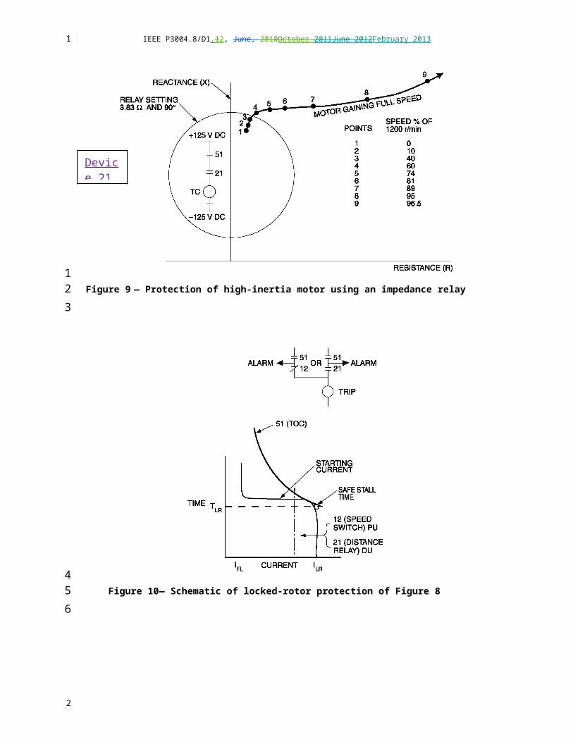
IEEE P3004.8/D1.12, June, 2010October 2011June 2012February 2013
Failure of diode bridge on rotating diodes on a brushless exciter (detected by pullout relays or a power-factor Device 55 element).
Reduced field-current conditions should be detected for the following reasons:
Overloaded motors pull out of step and stall.
Lightly loaded motors are not capable of accepting load when required.
Normally loaded motors, which do not pull out of step, are likely to do so on an ac voltage sag through which they might otherwise rideride through would be usual.
The excitation drawn from the power system by large motors maymight cause a serious system voltage drop and endanger servic continuity of service to other motors.
A common approach to field-current failure protection is to use an instantaneous dc undercurrent relay to monitor field current. This application should be investigated to ensure that no transient conditions would reduce the field current and cause unnecessary tripping of this instantaneous relay. A timer could be used to obtain a delay of one or more seconds. Connect, or the relay could be connected to alarm only where competent supervising personnel are available. Another approach is to use a constant-current source to monitor field resistance; a sudden lower reading indicates a ground fault. Some protection schemes inject a square wave into the field circuit, and monitor the returned signal for rounded edges that indicate a change in field coil conditions.
Field-current failure protection is also obtained by the generator loss-of-excitation relay that operates from the VTs and CTs that monitor motor stator voltages and current (VAR-import Device 40 and power-factor Device 55 protection). This approach has been done on some large motors (i.e., 3000 kW and above). This relay maymight also provide pullout protection (see 10.5.4.4)
8.5.3 Excitation voltage availability
Device 56 is a relay that automatically has automatic control ofs the application of the field excitation to an ac motor at some point in the trip cycle, probably more related to permissive control function. This device is a frequency relay, but others apply a simple voltage relay as a permissive start to ensure that voltage is available from the remote exciter. This approach avoids starting and then having to trip because excitation was not available. Loss of excitation voltage is not normally used as a trip; the field-current failure protection is used for this function.
8.5.4 Pullout protection (Device 55)
Pulling out of step is usually detected usually by one of the following relay schemes:
a) A power- factor relay (Device 55) responding to motor stator voltage and current VTs and CTs. See 10.5.4.5 about the need to delay actuation of the pullout relay until the machine has a chance to pull into synchronism during a calculated period.
b) An instantaneous relay connected in the secondary of a transformer whose with the primary carries carrying the dc field current. The normal dc field current is not transformed. When the motor pulls out of step, alternating currents are induced in the field circuit and transformed to operate the pullout relay. This relay, while inexpensive, is sometimes subject to false tripping on ac transients accompanying external system fault conditions, and also ac transients caused by pulsations in reciprocating compressor drive applications. Device 95 has sometimes been used to designate this relay.
1
12
34
5
6
78
910
111213141516171819
20212223
24
252627282930
31
32
333435
36373839404142
2
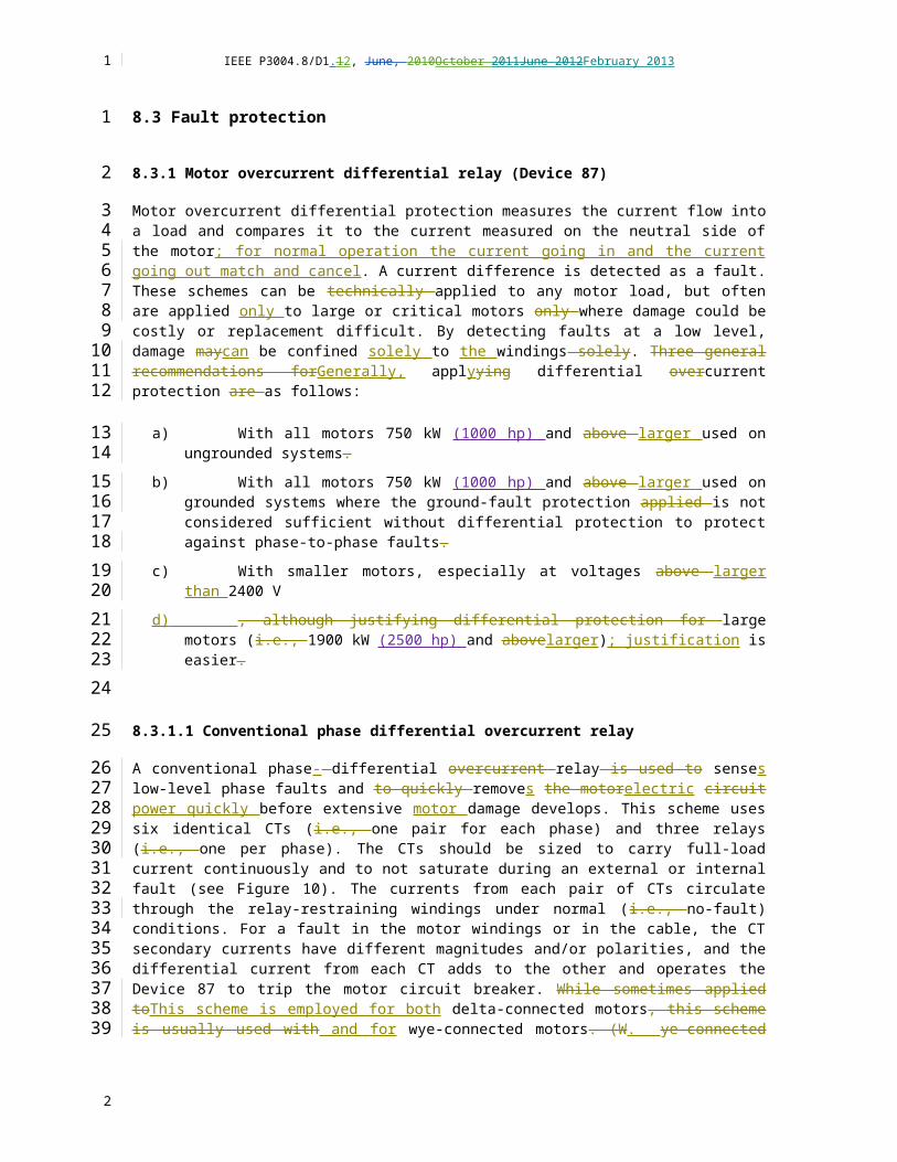
IEEE P3004.8/D1.12, June, 2010October 2011June 2012February 2013
c) The generator loss-of-excitation relay (Device 40).
8.5.5 Incomplete starting sequence (Device 48)
Incomplete starting sequence protection is normally a timer that blocks tripping of the field-current failure protection and the pullout protection during the normal starting interval. The timer is started by an auxiliary contact on the motor starter, and it times for a preset interval that has been determined during test starting to be slightly greater than the normal interval from start to reaching full field current. The timer puts the field-current failure and pullout protection in service at the end of its timing interval. This timer is often a de-energize-to-time device so that it is fail-safe with regard to applying the field-current failure and pullout protection.
8.5.5.1 Operation indicator for protection devices
Many types of the protective devices discussed in 10.5.4.1 through 10.5.4.5 do not have operation indicators. Separate operation indicators should be used with these protective devices.
8.5.5.2 Induction motor protection
<maymight need to reorganize to put in induction/general section>
For induction motor incomplete starting sequence protection (Device 48), wound-rotor induction motors and reduced-voltage starting motors should have a timer applied to protect against failure to reach normal running conditions within the normal starting time. Such a de-energized-to-time device is started by an auxiliary contact on the motor starter and times for a preset interval, which has been determined during test starting to be slightly greater than the normal starting interval. The timer trip contact is blocked by an auxiliary contact of the final device that operates to complete the starting sequence. This device would be the final secondary contactor in the case of a wound-rotor motor, or it would be the device that applies full voltage to the motor stator. Incomplete sequence protection should also be applied to partsplit-winding and wye-delta motor-starting control, and to pony motor and other reduced-voltage sequential start schemes.
8.6 Protection against excessive starting
The following protections against excessive starting are available:
a) A timer element, started by an auxiliary contact on the motor starter, with contact arranged to block a second start until the preset timing interval has elapsed.
b) Stator thermal overcurrent overload elementsrelays (Device 49TC). , which provide some protection, with the degree ofThis protection dependsing upon the following:
1) The Normal duration and magnitude of motor inrush
2) Running thermal capacity previously developed
3) The relay-operating time at motor inrush and the cool-down time of the relay
4) The Thermal damper-winding protection on synchronous motors
5) Rotor over-temperature protection
1
1
2
3
456789
10
11
1213
14
15
161718192021222324
25
26
2728
2930
31
32
33
34
35
2
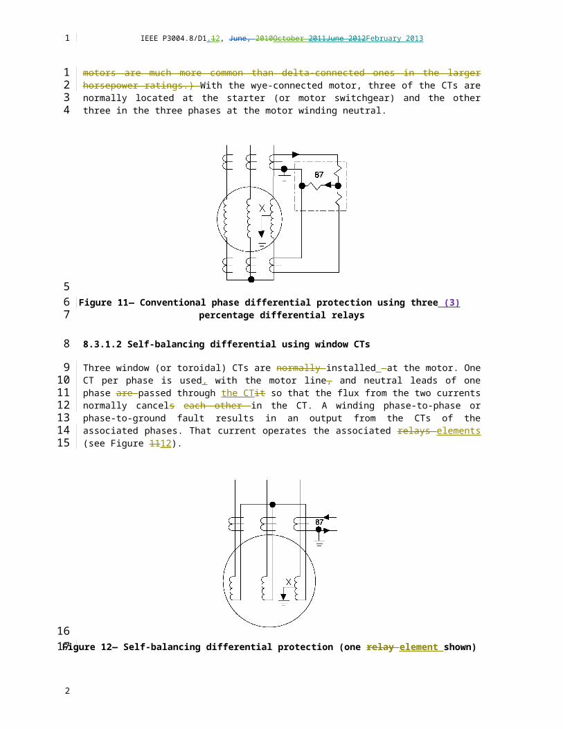
IEEE P3004.8/D1.12, June, 2010October 2011June 2012February 2013
c) Multifunction motor protection relays that have the capability to be programmed to limit the number of starts during a specific period (jogging protection). Large motors are often provided with nameplates giving their permissible start frequency of starting.
8.7 Rotor winding protection
8.7.1 Synchronous motors
The field and field supply should not be intentionally grounded intentionally. While the first ground connection does not cause damage, a second ground connection probably will cause damage. Therefore, detecting the first ground is important. The following methods are used:
a) Connect two lamps in series between field positive and negative with the midpoint between the lamps connected to ground. A ground condition shows by unequal brilliancy brilliance of the two lamps.
b) Connect two resistors in series between field positive and negative with the midpoint between the resistors connected through a suitable instantaneous relay to ground. The maximum resistance to ground that can be detected depends upon the relay sensitivity and the resistance in the two resistors. This scheme does not detect a ground fault at midpoint in the field winding. If a varistor is used instead of one of the resistors, then the point in the field winding at which a ground fault cannot be detected changes with the magnitude of the excitation voltage. This approach is used to overcome the limitation of not being able to detect a field midpoint ground fault.
c) Apply a small low ac voltage signal between the field circuit and ground, and monitor the ac flow to determine when a field-circuit ground fault occurs. (Note: bBefore using one of these schemes, a determination should be made that a damaging ac current will not flow through the field capacitance to the rotor iron and then through the bearings to ground and thus cause damage to the bearings).
If a portion of the field becomes faulted, damaging vibrations may can result. Vibration monitors and sensors should be considered.
8.7.2 Wound-rotor induction motors
The protection for wound-rotor induction motors is similar to the protection described for synchronous motors, except the field is three-phase ac instead of a dc field (see Figure 19). Yuen, et al. [B14], describe some operating experience which confirms the effectiveness of this protection. Wound-rotor motor damage can result due tofrom high-resonant torques from during operation with unbalanced impedances in the external rotor circuit on speed-controlled motors. Protection to detect this fault is available, although it has is seldom been used.
1
123
4
5
6
789
101112
13141516171819
2021222324
252627
28
293031323334
2

IEEE P3004.8/D1.12, June, 2010October 2011June 2012February 2013
Figure 20 — Rotor ground protection of wound-rotor motor
8.8 Lightning and surge protection
8.8.1 Types of protection
Surge arresters are often used often, one per phase connected between phase and ground, to limit the voltage to ground impressed upon the motor stator winding due tofrom lightning and switching surges. The need for this type of protection depends upon the exposure of the motor and its the related power supply to surges. Medium-voltage cables have capacitance in their shields that can attenuate a surge. Like many protective applications, the engineer should evaluate importance and replacement costs, as well. A study is recommended.
The insulation of the stator winding of ac rotating machines has a relatively smalllow impulse strength. Stator winding insulation systems of ac machines are exposed to stresses due tofrom the steady-state operating voltages and to from steep-wave-front voltage surges at large of high amplitudes. Both types of voltages stress the ground insulation. The steep-wave-front surges also stress the turn insulation. If the rise time of the surge is sufficiently steep enough (i.e., 0.1 µs to 0.2 µs), then most of the surge can appear across the first coil, the line-end coil; and its distribution in the coil can be nonlinear. This phenomenon can damage the turn insulation even though the magnitude of the surge is limited to a value that can be safely withstood by the ground wall insulation.
The surge arrester should be selected to limit the magnitude of the surge voltage to a value less than the motor insulation surge withstand [(or basic impulse insulation level ([BIL)].]). See Table 2.
The steepness of the surge wave front at the motor terminals is influenced by two time constants:
At the supply end, by the effect of system inductance, grounding resistance, and motor cable impedance
At the motor end, by cable impedance and motor capacitanceSurge capacitors are used, also connected between each phase and ground, to decrease the slope of the wavefront of lightning and switching surge voltages. As the surge voltage wavefront travels through the motor winding, the surge voltage between adjacent turns and adjacent coils of the same phase are lower for
1
12
3
4
56789
10
1112131415161718
1920
21
2223
24252627
2

IEEE P3004.8/D1.12, June, 2010October 2011June 2012February 2013
a wavefront having a decreased slope. (A less steep wavefront is another way of designating a wavefront having a decreased slope.) The recommended practice is to install a surge surge-protection package consisting of a three-phase capacitor and three surge arrestors.
Table 2— The equivalent BILs by present standard test for commerciallyused motor voltages
Rated voltage(V)
NEMA BIL(kV)
IEC BIL(kV)
2400 9 15
4160 15 22
13 800 51 60
The steep-wave-fronted surges appearing across the motor terminals are caused by lightning strikes, normal circuit breaker operation, motor starting, aborted starts, bus transfers, switching windings (or speeds) in two-speed motors, or switching of power- factor correcting capacitors. Turn insulation testing also imposes a high stress on the insulation system.
The crest value and rise time of the surge at the motor depend on the transient event taking place, on the electrical system design, and on the number and characteristics of all other devices in the system. These factors include, but are not limited to, the motor, the cables connecting the motor to the switching device, the conduit and conduit grounding, the type of switching device, the length of the switchgear bus, and the number of other circuits connected to the bus.
See IEEE Std C37.96-2000 for additional information on recommendations of the IEEE Surge Protection Committee.
8.8.2 Locations of surge protection
The surge protection should be located as close to the motor terminals (in circuit length) as feasible, preferably with leads of 1 m or less. The supply circuit should connect directly to the surge equipment first and then go to the motor.
Specifying that the surge protection be supplied in an oversized terminal box on the motor or in a terminal box adjacent to the motor is becoming more common. When surge protection is supplied in a motor terminal box, it must be disconnected before high-voltage dielectric testing of the motor is begunbegins. This step is a recognized inconvenience of this arrangement. A separate surge disconnecting device maymight be required.
If the motors are within 30 m of their starters or the supply bus, locating the surge arresters, but not capacitors, in the starters or supply bus switchgear is economical (but not as effective). In the latter case, one set of surge protection can be used for all the motors within that 30 m of the bus. Alternatively, this approach may can be used for the smaller motors, and individual separate surge protection installed at each larger motor. Neither of these remote methods is recommended, and neither nor is locating the surge protection at the line side of the motor disconnect recommended, because as the disconnect can also be located too distant to be effective.
1
123
45
6
789
10
1112131415
1617
18
192021
2223242526
27282930313233
2

IEEE P3004.8/D1.12, June, 2010October 2011June 2012February 2013
8.8.3 Application of surge protection
The following factors should be considered when applying surge protection:
a) When a medium-voltage motor is rated above greater than 370 kW (500 hp), surge arresters and capacitors should be considered.
b) When a 150 kW (200 hp) or larger motor or when a critical motor is connected to open overhead lines at the same voltage level as the motor, surge arrestors and capacitors should be considered.
c) Even when a transformer is connecting the motors to open overhead lines, surge protection is still required at times to protect against lightning or switching surges. Techniques are available to analyze this situation. If doubt exists, surge protection should be provided. Refer to 10.5.8.2 for surge protection on the supply bus for motors located remote from the bus. In addition, refer to Chapter 13 and Chapter 14, which recommend protection for switchgear and incoming lines.
d) Where certain vacuum or SF6 circuit breakers or vacuum contactors are used, surge protection maymight be necessary due tobecause of the possibility of restrikes, which can result in voltage spikes.
e) For application in Class I, Division 2 or Class I, Zone 2, nonsparking surge arresters, such as metal oxide varistor (MOV), sealed type, and specific- duty surge protective capacitors can be installed in general-purpose type enclosures. Surge protection types other than those described above require enclosures approved for Class I, Division 1 locations or Zone 1 locations. (See 2011 NEC Article 501.35(B) and 505.20(C)). Refer to IEEE 1349-2011
NOTE – For a motor application, using three single-phase, specific- duty surge capacitors avoids phase-phase short-circuit faults within the capacitor.
8.9 Protection against overexcitation from shunt capacitance
8.9.1 Nature of problem
When the supply voltage is switched offremoved, an induction motor initially continues to rotate and retains its the internal voltage. If a capacitor bank is left connected to the motor or if a long distribution line having significant shunt capacitance is left connected to the motor, the possibility of overexcitation exists. Overexcitation results when the voltage versus current curves of the shunt capacitance and the motor no-load excitation characteristic intersect at a voltage above the rated motor voltage.
The maximum voltage that can occur is the maximum voltage on the motor no-load excitation characteristic (sometimes called magnetization or saturation characteristic). This voltage, which decays with motor speed, can be damaging to a motor (see Figure 20 21 as an example).
1
1
2
34
567
89
10111213
141516
1718192021
2223
24
25
26
2728293031
323334
2

IEEE P3004.8/D1.12, June, 2010October 2011June 2012February 2013
Figure 21 — Excess shunt capacitance from utility line, which is likely tooverexcite a large, high-speed motpor
Damaging inrush can occur if automatic reclosing or transfer takes place on a motor that has a significant internal voltage due tofrom overexcitation.
8.9.2 Protection
When overexcitation is expected, protection can be applied in several ways. B, beginning with the simplest protection, which is of a separate contactor to drop out the capacitors when the motor power source is lost. The contactor could also be dropped outoperated by instantaneous overvoltage relay elements. An alternative is to use a high-speed underfrequency relay, which, however, maymight not be sufficiently fast enough on high-inertia or lightly loaded motors.
The underfrequency relay is not suitable for motors whose when frequency maymight not decrease following loss of the supply overcurrent protective disconnecting device. With these applications, a loss-of-power relay could be used. Examples of these applications are the following:
a) Mine hoist with overhauling load characteristic at time of loss of supply overcurrent device
f) Motor operating as induction generator on shaft with process gas expander
g) Induction motor with forced commutation from an ASD
1
123
4
56
7
89
101112
131415
16
17
18
19
2

IEEE P3004.8/D1.12, June, 2010October 2011June 2012February 2013
8.10 Protection against automatic reclosing or automatic transfer
8.10.1 Nature of problem
<Dan Ransom; lead; reference Dr. Murt?; compare to C37.96) When the supply voltage is removedswitched off, initially, motors initially continue to rotate and retain an internal voltage. This voltage decays with motor speed and internal flux. If system voltage is restored out-of-phase with a significant motor internal voltage, then high large inrush current can damage the motor windings or produce torques damaging to the shaft, foundation or drive coupling, or gears (see 10.3.2).
Fast reclosing on a motor bus is possible if the motor volts-per-hertz excitation level remains below 1.33. Any system that restores power must do so in less than 100 ms to prevent major damage . These systems must be studied to determine efficacy even when using fast, permissive synchronizing and fast-closing circuit breakers. The benefit of fast reclosing is continued process operation without long, costly downtime, which balances the risk and effort involved. IEEE Std C37.96-2000 discusses considerations for the probability of damage occurring for various motor and system parameters.
If fast reclosing cannot be obtained then closing must occur when motors on a bus have completed spinning and are nearly stopped. This is the residual closing range (time greater than 3 s or facility safe practice).One of the best methods to prevent fast reclosing is to consult with the power supplier to determine whether they can delay reclosing (e.g., 2 s or more or whatever becomes a standard practice).
8.10.2 Protection
The following protection alternatives should be considered:
a) Delay restoration of system voltage, using a timer (Device 62) for a preset interval sufficient for adequate decay of the motor internal voltage. This method maymight not be as necessary if the power supplier cooperates on the reclosing, but could be a backup device
b) , provided that the timer’s reliability is acceptable.
c) Delay restoration ofing system voltage until the internal voltage fed back from the motor(s) has dropped to a low enough value. Commonly, tThis residual closing value is commonly considered to be 25% percent of rated voltage. The frequency also decreases as the voltage decays due tobecause of motor deceleration. The undervoltage relay element (Device 27) and its setting should be chosen accordingly to include a full-wave rectifier and a dc coil and to make the relay element dropout independent of frequency. If an ac frequency-sensitive relay is used, it should be set (based on motor and system tests) to actually drop out at 25% of rated voltage and at the frequency that will exist when 25% of rated voltage is reached.
h) Use a high-speed under-frequency relay element (Device 81) to detect the supply outage and trip the motors before supply voltage is restored. A limitation exists if the motor operates at the same voltage level as the supply lines on which faults may occur followed by an automatic reclosing or transfer operation. The problem is that the under-frequency relay requires some voltage in order to have operating torque. If no impedance (e.g., a transformer) exists between the motor and the system fault location, then the voltage may not be sufficient to permit the under-frequency relay to operate. Digital frequency relays are not as voltage limited as electromechanical relays.
i)
j) Use single-phase (Device 27) or three-phase undervoltage relays elements as follows:
1
1
2
34567
89
10111213
14151617
18
19
202122
23
2425262728293031
3233343536373839
40
41
2

IEEE P3004.8/D1.12, June, 2010October 2011June 2012February 2013
1) One relay element with a sufficiently fast time setting can be connected to the same VT as the under-frequency relay [see Item c)] and sense the fault condition that results in insufficient voltage to operate the under-frequency relayelement.
2) One, two, or three relay elements (i.e., each connected to a different phase) can be used to detect the supply outage and trip the motors when sufficient time delaydelay exists before the supply is restored.
k) Use a loss-of-power (undercurrent) relay element (Device 37). This under-power relayelement should be sufficiently fast and sensitive. A high-speed three-phase relay has been used frequently, butThis element should be active only in the motor running state (blocked at startup) until when sufficient load is obtained on the circuit or motor with which it is applied.
l) Use a reverse-power relay element (Device 32). This relay element detects a separation between motors and their source. While this approach is suitable in some circumstances, generally the loss-of-power relay element application is generally more suitable than the reverse-power relay element application due tobecause of the following limitations:
1) During the fault, when the source is still connected to the motors, net power flow continues into the motors for low-level faults. Although not true for three-phase bolted faults, low-level faults have a very low impedance, into which reverse power flows.
2)
3) Usually, tTripping by reverse power can usually be reliedis effective upon only if a definite load remains to absorb power from high-inertia motor drives after the source -fault-detecting relays elements isolate the source from the motors.
4) Reverse-power relays responsive to reactive power (i.e., vars) instead of real power (i.e., watts) usually do not provide a suitable means of isolating motors prior to automatic reclosing or automatic transfer operations.
8.11 Protection against excessive shaft torques
< Dan Ransom; lead >A phase-to-phase or three-phase short circuit at or near the synchronous motor terminals produces high shaft torques that may can be damageing to the motor or driven machine. Computer programs have been developed for calculationng of these torques. Refer to IEEE Std C37.96-2000 for information on this potential problem.
To minimize exposure to damaging torques, a three-phase, high-speed undervoltage relay element (Device 27) can be applied to detect severe phase-to-phase or three-phase short-circuit conditions for which the motors should be tripped. This relay is often the type whose torque is proportional to the area of the triangle formed by the three voltage phasors. A severe reduction in phase-to-phase or three-phase voltage causes tripping. Addn additional tripping delay of 1 cycle to 8 cycles (15 ms to 500 ms) may be satisfactory from a protection point of view and desirable to avoid unnecessary shutdowns. This protection can be achieved using a suitable timer. Selection of protection and settings for this application should be done in cConsultation with the suppliers of the motors, driven machines, and protection devices when creating protection settings.
8.12 Protection against excessive shaft torques developed during transfer of motors between out-of-phase sources
< Dan Ransom; lead >A rapid transfer of large motors from one energized power system to another energized power system could cause very high motor inrush currents and severe mechanical shock to the motor. The abnormal inrush currents maymust be sufficient be high enough to trip circuit breakers or blow
1
123
456
789
10
11121314
151617
18
192021
222324
25
26
27282930
313233343536373839
4041
424344
2

IEEE P3004.8/D1.12, June, 2010October 2011June 2012February 2013
fuses, and these currents could damage motor system components. The mechanical jolt could physically damage the motor, shaft, and couplings.
These effects can occur in emergency or standby power systems when a motor is de-energized and then rapidly reconnected to another source of power that is out-of-phase with the motor’s regenerated voltage. Motors above 37 kW driving high-inertia loads (e.g., centrifugal pumps, fans) may require special consideration.
The problem can be eliminated if the motor circuits can be de-energized long enoughfor sufficient time to permit the residual voltage to decay before power is again applied to the motor. This step can be done in two ways. In one available method, auxiliary contacts or a relay on the automatic transfer switch can open the motor holding coil circuits, while the transfer is delayed about 3 s. This method is sometimes effective, but requires interwiring between the transfer switch and the motor starters and depends upon the reliability of a timing device. Another method utilizes a transfer switch with a timed center-off position. The switch opens, goes to the neutral or off position, is timed to stay there about 3 s to 10 s, and then completes the transfer. This approach eliminates any interwiring to the motors. The required time delaydelay should be set carefully set and may can vary as the system conditions change. A third position (neutral) creates the danger that the transfer switch maymight remain indefinitely in a neutral position in the event of a control circuit or contactor malfunction.
Another solution is to momentarily parallel momentarily the two power sources on transfer, connecting both sources together and then dropping one out. This approach is completely effective because power to the motors is never interrupted. However, it can require new equipment and can be costly. If one source is utility power, a problem may can exist occur in becausethat some utilities do not permit paralleling another source with their systems. In obtaining permission for the paralleling from the utility, a design review may can lead to additional protective relaying. An additional factor is that the combined available fault current maymight exceed the ratings of the connected electrical switching equipment.
In-phase transfer is another solution to the problem. An accessory on the transfer switch, known as a fast n in-phase monitor or synch-check element (Device 25), measures the phase-angle difference between the two power sources. An on-site generator set would be controlled by an automatic synchronizer, which recognizes that the two sources continually go in and out of phase. At the proper window or acceptable phase-angle difference between the sources, the synchronizer synch-check element initiates transfer. The design allows for the operating time of the transfer switch so that the oncoming source is connected to the motors in phase or at a phase difference small enough to eliminate excessive inrush currents and mechanical shock. No special field adjustments or interwiring to the motors are required. For typical transfer switches with transfer times of 10 cycles (166 ms) or less and for frequency differences between the sources of up toas much as 2 Hz, the fast synchro-check relay element provides a safe transfer of motors.
8.13 Protection against failure to rotate
8.13.1 Failure to rotate
A failure to rotate occurs when the supply is single phased or if the motor or driven machine is jammed. The following protection is available:
a) Relays may can be used to detect single phasing (see 10.3.3.2).
m) The direct means to detect failure to rotate is to use a shaft-speed sensor and timer to check whether a preset speed has been reached by the end of a short preset interval after energizing the motor. This protection is necessary for induction and brushless synchronous motors that have a permissible locked-rotor time less than normal acceleration time.
1
12
3456
789
1011121314151617
18192021222324
2526272829303132333435
36
37
3839
40
41424344
2

IEEE P3004.8/D1.12, June, 2010October 2011June 2012February 2013
n) For induction and brushless synchronous motors having a permissible locked-rotor time greater than normal acceleration time, relying upon the element 49TC thermal overload element is preferred. Using an inverse-time phase-overcurrent relays (Device 51) as a backup is normal (see 10.3.4 and 10.3.5).
o) For brush synchronous motors having a permissible locked-rotor time less than normal acceleration time, one method of protection is to use a frequency-sensitive relay connected to the field discharge resistor and a timer because the frequency of the induced field current flowing through the discharge resistor is related to the motor speed. A frequency-sensitive adjustable time-delay voltage relay is also available to provide this protection.
p) For brush synchronous motors having a permissible locked-rotor time greater than normal acceleration time, relying upon the damper-winding protection and incomplete starting sequence protection is normal.
q) For a large induction motor protection to start, an impedance relay element (Device 21) may can be applied (see 10.5.1, Figure 8, and Figure 9).
8.13.2 Reverse rotation; loss of phase
A directional speed switch mounted on the shaft and a timer can be used to detect starting with reverse rotation. Some motor loads are equipped with a ratchet arrangement to prevent reverse rotation.
A reversal in the phase rotation, or a phase loss, can be detected by a reverse-phase voltage relay element (Device 47) [see 10.3.3.4 b)] if the reversal or loss occurs in the system on the supply side of the relay. This relay element cannot detect a reversal or loss that occurs between the motor and the point at which the relay element is connected to the system. Set this element for no more than 5 percent voltage imbalance. Unbalanced voltages create large unbalanced currents (approximately five times the percent voltage unbalance); these negative-sequence currents can damage motor stator windings. A backup method for preventing unbalanced power system damage is using a current-imbalance element (Device 46). Set this element to 0.2 pu negative-sequence current.
A directional speed switch mounted on the shaft and a timer can be used to detect starting with reverse rotation. Some motor loads are equipped with a ratchet arrangement to prevent reverse rotation.
9. Application considerations
9.1 Motor protection for ASD applications
<[Ed Larsen, Lead; Jeff Hensley; Dan Neeser, Tim O’Hearn; add ASD application information for medium-voltage and low-voltage applications; eg high speed fuses, shaft currents CMV, resonant frequency, partial discharge, long lead length NEMA Part 30 & 31 (inverter duty); things that are different because of ASD (no surge arrestors) (no Power Factor correction capacitors) see also C37.96-2012 draft]>
<Comments and questions are shown in italics.>
<Blue text extracted or based on the NEC is shown in blue and maymight need to be rewritten>
<Brown text: note from Dec 10, 2012 WG meeting>
1
1234
56789
101112
1314
15
1617
1819202122232425
2627
28
29
30
31323334
35
36
37
2

IEEE P3004.8/D1.12, June, 2010October 2011June 2012February 2013
9.1.1 Terminology
Adjustable speed drives (ASD) are known by many names, such as:
Adjustable Frequency Controller (AFC) – refers to ac drives
Adjustable Frequency Drive (AFD) – refers to ac drives
Adjustable Speed Drive (ASD) – refers to ac or dc drives
Inverter – refers to ac drives
Power converter – refers to ac drives
Variable Frequency Drive (VFD) – refers to ac drives
Variable Speed Drive (VSD) – refers to ac or dc drivesThere is no single industry recognized name. In this section they will be referred to as ASDs, as does the IEEE and the National Electrical Code® (NEC®).
9.1.2 Low Voltage AC Drive Motor Protection
9.1.2.1 Protection
Use some of the content in: Electric Motors and Variable Frequency Drives Handbook Vol. 4, The Electricity Forum, pages 47-48, 59-60? http://www.meisterintl.com/PDFs/Electric-Motors-Drives-Vol-4.pdf
Use some of the content in: Adjustable Speed Drive Motor Protection Applications and Issues, Jon Gardell, Chairman Prem Kumar, Vice Chairman, Rotating Machinery Protection Subcommittee of the IEEE Power System Relaying Committee Working Group?
How does what we are writing fit in with this paper?
Use some of the content in: Draft Guide for AC Motor Protection, Power System Relaying Committee of the IEEE Power Engineering Society, IEEE Std PC37.96/D10? Possible topics might be:
5.1 Pullout and stall protection
5.2 Stator winding protection
5.3 Rotor thermal protection
5.4 Stator fault protection
5.5 Rotor fault protection
5.6 Bearing protection
5.7 Abnormal power supply conditions WG: need to cover here or elsewhere, but drive may automatically protect against these conditions, delete
5.8 Surge protection LP: need, but coordinate with coverage elsewhere in docHow does what we are writing fit in with this standard? LP: our doc needs to stand alone
1
1
2
3
4
5
6
7
8
91011
12
13
14
15
161718
192021
22
2324
25
26
27
28
29
30
3132
3334
2

IEEE P3004.8/D1.12, June, 2010October 2011June 2012February 2013
LP: Need to show drive topology?
Use some of the content in: NEMA Application Guide for AC Adjustable Speed Drive Systems, Bezesky and Kreitzer, PCIC 2001-7? Bredhold: get 2007 edition
Use some of the content in: Application issues for PWM adjustable speed AC motor drives, von Jouanne et al, Industry Applications Magazine Sept/Oct 1996?
9.1.2.2 Included in ASD
Where the ASD is marked to indicate that motor overload protection is included, additional overload protection is not required.
WG: can’t assume that the drive provides OL protection, need to look for marking
9.1.2.3 Bypass Circuits
For ASD systems that utilize a bypass device to allow motor operation at rated full-load speed, motor overload protection must be provided in the bypass circuit.
WG: Must be provided when in bypass mode, does not necessarily need to be in the bypass ckt itself
9.1.2.4 Multiple Motor Applications
For multiple motor applications, individual motor overload protection shall be provided in accordance with NEC® Article 430, Part III.
Use some of the content in: Application Guide for AC Adjustable Speed Drive Systems, NEMA, 5.2.12 pg. 49-50?
DN: yes, multiple motors & group motor applications (contact John McKensie & Mike Liptak from SE)
9.1.2.5 Overtemperature Protection
Overheating of motors can occur even at current levels less than a motor’s rated full-load current. Overheating can be the result of the shaft-mounted fan operating at less than rated nameplate RPM. For motors that utilize external forced air or liquid cooling systems, overtemperature can occur if the cooling system is not operating. In these instances, overtemperature protection using direct temperature sensing is recommended, or additional means should be provided to ensure that the cooling system is operating (flow or pressure sensing, interlocking of ASD system and cooling system, etc.)
1
1
23
45
6
7
89
10
11
12
1314
15
16
17
1819
2021
22
23
24
252627282930
2

IEEE P3004.8/D1.12, June, 2010October 2011June 2012February 2013
ASD systems must protect against motor overtemperature conditions where the motor is not rated to operate at the nameplate rated current over the speed range required by the application. Such protection may be provided by:
Motor thermal protector in accordance with 430.32
Adjustable speed drive system with load and speed-sensitive overload protection and thermal memory retention upon shutdown or power loss, except that thermal memory retention upon shutdown or power loss is not required for continuous duty loads.
Overtemperature protection relay utilizing thermal sensors embedded in the motor and meeting the requirements of 430.32(A)(2) or (B)(2).
Thermal sensor embedded in the motor whose communications are received and acted upon by an ASD system.
For multiple motor applications, individual motor overtemperature protection shall be provided as required in 430.126(A).
Use some of the content in: Application Guide for AC Adjustable Speed Drive Systems, NEMA, 5.2.1.3 pg. 29, 5.2.1.5 pg. 30?
9.1.3 Medium Voltage AC Drive Motor Protection
Use some of the content in: The protection technology of high voltage variable frequency drive system, Qing Xion et al, IEEE paper?
WG: refer to IEEE 1566. Currently being updated. Ballot next year. LP will get me in contact with that WG, Rick Paes.
9.1.4 DC Drive Motor Protection
Use some of the content in: Electric Motors and Variable Frequency Drives Handbook Vol. 4, The Electricity Forum, pages 41-46? http://www.meisterintl.com/PDFs/Electric-Motors-Drives-Vol-4.pdf
LP: Chris Heron can help
9.1.5 Other Considerations
9.1.5.1 Shaft Voltage and Bearing Currents and Common Mode Voltages
Use some of the content in: Application Guide for AC Adjustable Speed Drive Systems, NEMA, 5.2.10 pg. 44-49?
LP: IEEE 1349 has new section on CMV calculations
1
123
4
567
89
10111213
1415
16
17
1819
2021
22
23
2425
26
27
28
29
30
3132
33
2
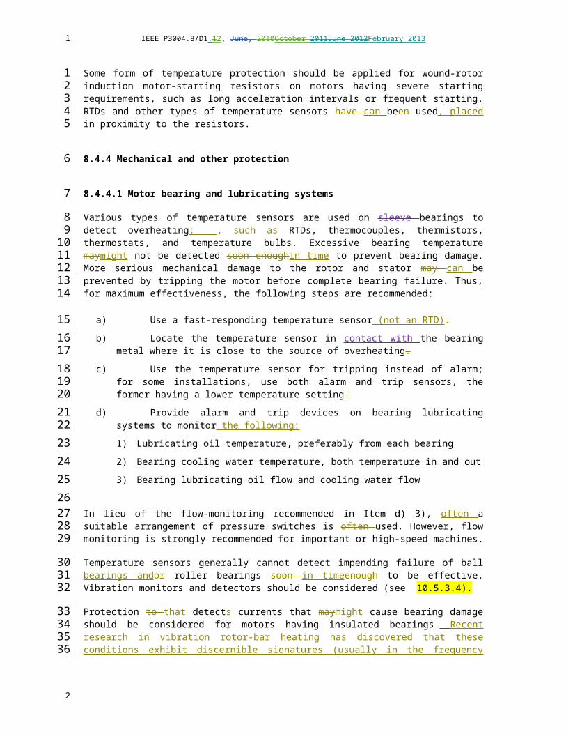
IEEE P3004.8/D1.12, June, 2010October 2011June 2012February 2013
9.1.5.2 Partial Discharge
WG: Chris Heron met with others (Malcolm Seltzer-Grant) on this topic for section 8. Usually an issue at 5kV and above, but inverters can lower that level, seen as low as 2.3kV and even down to 480V. Need to describe phenomenon or protection? Need to cover. Have seen 4kV in other stds. Can happen if drive is closely coupled to machine. IEC stds. Write paragraph that phenomenon & protection not the same when a drive is used, refer to section 8. Protection is in way motor is wound. PD monitor (negative seq.). Motor mfgrs may use higher insulation level if they know motor will be on a drive.
9.1.5.3 ASD Output filters and reactors
Use some of the content in: Electric Motors and Variable Frequency Drives Handbook Vol. 4, The Electricity Forum, pages 47-52? http://www.meisterintl.com/PDFs/Electric-Motors-Drives-Vol-4.pdf
Use some of the content in: Application Guide for AC Adjustable Speed Drive Systems, NEMA, 5.2.9 pg. 38-44?
WG: Need to cover? Yes. Reflected wave issue, inverter duty withstands better. Consider dV/dt filters.
WG: Need to cover (dV/dt filters). Can also be addressed in drive topology. Related to long lead length issue. Get David Shipp to help. Move this topic to long lead length section. Call the section “ASD Output Filters and Reactors” rather than “Long Lead Length”.
9.1.5.4 NEMA MG-1 Part 30 and 31 Inverter Duty
Use some of the content in: Application Guide for AC Adjustable Speed Drive Systems, NEMA, 5.2.9.1 pg. 38?
Part 30 covers general purpose motors
Part 31 covers inverter duty motors
WG: Need to cover? Yes, because protection needs vary depending on type of motor.
WG: Need to cover duty cycle, re motor heating. Maybe in a separate section? Under thermal protection?
9.1.6 Selecting Drives
Since the scope of this dot standard, and this specific section, is motor protection, do we/should we cover selection of the drive itself? I think not, but if the answer is yes, subtopics might be:
9.1.6.1 Selection Considerations
1) Load characteristics
2) Motor nameplate data
3) Motor speed control range, heating and performance considerations
4) Breakaway torque requirements
1
1
234567
8
9
1011
1213
14
151617
18
1920
21
22
23
24
25
2627
28
29
30
31
32
2

IEEE P3004.8/D1.12, June, 2010October 2011June 2012February 2013
5) Load acceleration/deceleration requirements
6) Environment (temperature, altitude, humidity)
7) Multimotor or single motor
8) AC line
9) Code requirements
10) Application considerationsWG: Need to cover? Not for drive per se, but need to cover protection options that might be needed in the drive. Reference earlier sections. Break down into LV & MV. In MV multifunction relay will provide necessary options.
Write introductory paragraph. Assuming the drive selected is adequate, then need to provide protection considerations…(punch list). Reference IEEE 1566 data sheet.
9.1.6.2 Regeneration and Dynamic Braking
Use some of the content in: Application Guide for AC Adjustable Speed Drive Systems, NEMA, 5.2.5 pg. 36-37?
WG: Need to cover? Deals with drive protection, not motor protection? What about dc injection braking? What about mechanical braking? Yes, we need, but unsure what to say. Leave in for now.
Need separate subsection: if compressor or pump sled provides protection function/monitoring (RTD, vibration) need coordination between sled and drive. David Rains will write.
9.1.6.3 Protection Device Monitoring by Auxiliary Control Equipment
In some applications vibration and temperature monitoring devices may be monitored by an auxiliary control panel; e.g. compressor or pump unit control panel, DCS or station control panel. In these applications; permissive to start, alarm and shutdown signals shall be coordinated with the drive to ensure the protection of the motor and the driven equipment.
9.1.7 Drive Protection
Since the scope of this dot standard, and this specific section, is motor protection, do we/should we cover protection of the drive itself? I think not, but if the answer is yes, subtopics might be:
WG: Need to cover? Yes, to the extend that the motor branch circuit overcurrent protection also protects the motor. Will touch on it somehow.
1
1
2
3
4
5
6789
1011
12
13
1415
1617
1819
20
21222324
25
26
2728
2930
31
32
2

IEEE P3004.8/D1.12, June, 2010October 2011June 2012February 2013
9.2 Motors protection for hazardous (classified) locations
[<Lorraine Padden, lead; Tim O’Hearn; add application information for hazardous (classified) location applications]
9.3 DC Motor protection
<Chris Heron, lead. Jim Bryan;. Add application information.>
1
1
2
3
45
6
7
8
9
2

IEEE P3004.8/D1.12, June, 2010October 2011June 2012February 2013
Annex A Bibliography
[B1] Bradfield, H. L., and Heath, D. W., “Short-Circuit Protection of Energy-Efficient Motors,” IEEE Industry Applications Magazine, vol. 3, no. 1, pp. 41–44, Jan./Feb. 1997.
[B2] Gregory, G. D., “Single-Pole Short-Circuit Interruption of Molded-Case Circuit Breakers,” IEEE I&CPS Conference Record, Section 5, Paper 1, pp. 1–8, May 1999.
[B3] Gregory, G. D., and Padden, L. K., “Application Guidelines for Instantaneous Trip Circuit Breakers in Combination Starters” (a working group report), IEEE Transactions on Industry Applications, vol. 34, no. 4, pp. 697–704, July/Aug. 1998.
[B4] Gregory, G. D., and Padden, L. K., “Testing and Applying Instantaneous Trip Circuit Breakers in Combination Motor Starters,” IEEE PCIC Conference Record, pp. 41–49, 1998.
[B5] Love, D. J., “Ground Fault Protection of Electric Utility Generating Station Medium-Voltage Auxiliary Power System,” IEEE Transactions on Power Apparatus and Systems, vol. PAS-97, No. 2, March/April 1978, pp. 583–586.
[B6] Love, D. J. and Hashemi, N., “Considerations for Ground Fault Protection, Medium-Voltage Industrial and Co-Generating Systems,” IEEE Transactions on Industry Applications, vol. IA-24, July/August 1988, pp. 548–553.
[B7] Nailen, R. L., Managing Motors, 1st ed. Chicago: Barks Publications, Inc., 1991, pp. 4-61 and 4-62.
[B8] Nailen, R. L., “Motor Inrush Current: What Does It Really Mean?” Electrical Apparatus Magazine, pp. 56–60, June 1986.
[B9] NEMA MG 10-1994, Energy Management Guide for Selection and Use of Fixed Frequency Medium AC Squirrel-Cage Polyphase Induction Motors.
[B10] Padden, L. K., and Pillai, P., “Simplifying Motor Coordination Studies,” IEEE Industry Applications Magazine, vol. 5, no. 2, pp. 38–52, Mar./Apr. 1999.
[B11] Prabhakara, F. S., Smith Jr., R.L., and Stratford, R. P., Industrial and Commercial Power Systems Handbook, 1st ed. Mcgraw-Hill, 1995, pp. 8–46.
[B12] Smith III, A. J., “Short Circuit Ratings, Labels and Fault Withstandability of Molded-Case and Insulated-Case Circuit Breakers and Combination Motor Starters,” IEEE PCIC Conference Record, pp. 9–18, 1991.
[B13] UL 489, Standard for Molded Case Circuit Breaker and Circuit Breaker Enclosure.
[B14] Yuen, M. H., Rittenhouse J. D., and Fox F. K., “Large Wound-Rotor Motor with Liquid Rheostat for Refinery Compressor Drive,” IEEE Transactions on Industry and General Applications, vol. IGA-1, pp.140–149, Mar./Apr. 1965.
<add new reference [BB#]..>
1
1
23
45
678
910
111213
141516
17
1819
2021
2223
2425
262728
29
303132
33
2

IEEE P3004.8/D1.12, June, 2010October 2011June 2012February 2013
Annex B Protection setting considerations
<Table and Annex B material added from comments submitted November 2012>
B.1 Typical motor protection settings
Typical recommended protection settings for motor protection devices are shown below:
Table B.1 Typical motor protection device settings
Descriptions Alarm TripThermal overload 105% (110% = SF 1.0), (125% = SF 1.15)Unbalance (voltage, current) ±10% ±15% - 20%Ground fault 0.1 ground CT 0.15 ground CTUnder/Over Voltage ±10% ±15% – 20%Stator winding temperature -15oC insulation max -10oC insulation macBearing temperature 15 oC before damage 10 oC before damageShort circuit 600% - 720%
B.2 Current unbalance and ground fault protection in HRG system
<If users set current unbalance protection relay to trip under High Resistance Ground (HRG) system and there is a ground fault on the system, current unbalance relay will initiate an undesired trip against ground fault. Therefore, I would like to recommend alarm only for current unbalance relay in the HRG system. Of course, some protection relay for LV application may have some blocking function to avoid this situation.>
B.3 Overcurrent protection in fixed capacitor applications
<Although it is not popular PF correction application in industry for new plants, a fixed motor capacitor will still be a viable option for existing plants.
1. Dependent upon the capacitor location, overload or overcurrent setpoint should be adjusted.
2. Fixed capacitor will modify motor open circuit time constant. We may add some equations to calculate a revised motor open circuit time constant to help engineers to determine the minimum time for blocking motor starting until motor residual voltage reaches to an acceptable level.
3. Many process plants tends to implement motor re-acceleration scheme. Therefore, motor capacitor application may not be recommended for re-acceleration motors in the process plants unless there will be sufficient time to decay motor residual voltages. This should be discussed with plant process engineers.>
1
1
2
3
4
5
6
7
8
9101112
13
1415
16
171819
202122
23
2