ang 2010-09-01 Manuel Caneco HT-ENG V2.5 RevMKT11-2011...To the maximum extent permitted by...
128
REFERENCE MANUAL Calculation and diagrams for High Voltage electrical installations
Transcript of ang 2010-09-01 Manuel Caneco HT-ENG V2.5 RevMKT11-2011...To the maximum extent permitted by...
REFERENCE MANUAL
Calculation and diagrams
for High Voltage electrical installations
Ca
nec
o H
T
1, bd Charles de Gaulle
F-92700 COLOMBES - FRANCE
Tel: +33 (0)1 47 52 97 27
Fax: +33 (0)1 47 52 95 60
E-mail : [email protected] - web : www.caneco.eu
Refe
renc
e m
anua
l
Reference Manual
CANECO HT
Version 2.5
Calculations and diagrams of electrical installations
www.caneco.eu September 2010


ALPI - 2010 Caneco HT ©
Reference Manual Table of Contents - 3
Table of Contents 1 Licence Agreement 5 2 Installation 7
2.1 Purpose of this manual 7 2.2 Required knowledge 7 2.3 Minimum system requirements 7 2.4 Recommended system 7 2.5 Caneco HT protection 7 2.6 Installing Caneco HT 8 2.7 Uninstalling Caneco HT 8 2.8 Updating Caneco High Voltage 8 2.9 Contents of Caneco HT 9 2.10 Database Directory 9 2.11 Annotations 10
3 Purpose of the Software - Definitions 11 3.1 Purpose 11 3.2 Description of Caneco HT software 11 3.3 Definitions 12 3.4 Standards and reference documents 12
4 Caneco HT interface 13 4.1 Caneco HT interface overview 13 4.2 Menu bar 14 4.3 Menu commands 15 4.4 Buttons 15
5 The library area menus 21 5.1 Library area: File menu 21 5.2 Library area: Edit menu 22 5.3 Library area: Symbol menu 23 5.4 Library area: Display menu 24 5.5 Library area: Option menu 25 5.6 Library area: Window menu 32 5.7 Library area: Help menu 32
6 Workspace menus 33 6.1 Workspace: File menu 33 6.2 Workspace: Edit menu 42 6.3 Workspace: Modify menu 46 6.4 Workspace: Display menu 48 6.5 Workspace: Project menu 52 6.6 Workspace: Options menu 77 6.7 Workspace: Window menu 77 6.8 Workspace: Help menu 78
7 Symbols 79 7.1 General 79 7.2 Library overview 79 7.3 Create a symbol 81
8 Electrical symbols 83 8.1 Incoming Supply 83 8.2 Supply Generator 88 8.3 Earthing by zero sequence generator 94 8.4 Board 94 8.5 Two-winding transformer 95 8.6 Three-winding transformer 99 8.7 Asynchronous motor 100 8.8 Synchronous motor 104 8.9 Static load 105
Caneco HT © ALPI - 2010
4 - Table of Contents Reference Manual
8.10 Protections 106 9 Printing calculations 107
9.1 General 107 9.2 Report preview 107
10 Glossary of the comprehensive folder 109 10.1 Network data 109 10.2 Calculation results 109
11 Warnings and remarks 111 11.1 General information about alerts and remarks 111
ALPI - 2010 Caneco HT ©
Reference Manual Licence Agreement - 5
1 Licence Agreement
End-User Licence Agreement for Caneco HT® software.
1. IMPORTANT – TO BE READ CAREFULLY Please read this summary of License Agreement, as well as the full version of the “LICENCE AGREEMENT” presented in the SOFWARE, before installing or using this software. Only the full version, as shown when installing the software constitutes the entire agreement concluded between the LICENSEE and ALPI and replace any other agreement or communication made prior the present one concerning this SOFTWARE. By installing or using this SOFTWARE, you agree to be bound by the terms of this license. If you did not obtain this copy of the software legally, please immediately destroy the copy. If you do not accept these terms, promptly cease all further installation or use of the software. It is understood that certain restrictions included in this Agreement apply only to Caneco HT® software.
2. DEFINITIONS In this Agreement: -"ALPI" means Applications Logiciels Pour l’Ingénierie S.A. -"LICENSE AGREEMENT" means this Agreement and any other document which is included hereunder. -"LICENSEE" means you, the user of the SOFTWARE. - "SOFTWARE" means the Caneco HT software used by the LICENSEE, named Caneco HT® and/or CANECO HT for the purpose of this Licence contract, including any technology and utility software used by CANECO HT under a license granted to ALPI by developers and owners of this technology or utility, and any attached documentation.
3. LIMITED WARRANTY AND LIABILITY ALPI does not guarantee nor claims that the SOFTWARE functions described in the Manual comply with the requirements of the LICENSEE or that the operation of the SOFTWARE will be uninterrupted or error-free. All software and other devices provided with the SOFTWARE or attached to it are not guaranteed by ALPI. The SOFTWARE and the Manual furnished herewith, are provided "AS IS" without warranty of any kind, either expressed or implied, including, but not limited to, the implied warranties of merchantability and fitness for a particular purpose, or of any other type, whether expressed or implied, and to any remedy against ALPI and/or its licensors, whether in contract, tort, delict, quasi-delict or otherwise. Some jurisdictions do not allow the exclusion of certain implied warranties, so the preceding exclusions may not apply. To the maximum extent permitted by applicable law, in no event, shall ALPI and/or its licensors be liable for any special, consequential, incidental or direct or indirect damages (including without limitation loss of profit) arising out of the LICENSEE’s use or inability to use the SOFTWARE or printed information accompanying it, whether or not ALPI and/or any of its licensors have been advised of the possibility of such loss, however caused and on any theory of liability. This exclusion also includes any liability that may arise out of third party claims against the licensee.
4. COPYRIGHT - LICENCE Caneco HT® is protected by the laws concerning copyright and by the provisions of laws and international treaties on intellectual property. Caneco HT® is not sold but granted under license In return of the LICENSEE's agreement to comply with the terms and conditions of this License Agreement, ALPI grants to the LICENSEE a non-exclusive and non-transferable license to use the SOFTWARE and consult the documentation on a single computer system. It is also agreed that the License granted to the LICENSEE, concerning Caneco HT®, is non-transferable. The LICENSEE may not use the SOFTWARE on a network server or on more than one computer terminal at the same time, except in case of a commercial agreement previously provided by ALPI. This Agreement does not grant the LICENSEE any rights to patents, copyrights, trade secrets, trade names, trademarks (whether registered or unregistered), or any other rights, functions or licenses in respect of the SOFTWARE.
5. COPYRIGHT AND RESTRICTIONS ON THE USE The SOFTWARE and its Manual contain copyrighted material and, in their humanly readable form, contain trade secrets and proprietary information owned by, or licensed to, ALPI. Title to, and ownership of, the SOFTWARE and the documentation that accompanies the SOFTWARE and all intellectual property rights in the SOFTWARE and said documentation are, and shall remain, the sole property of ALPI and/or its licensors. The LICENSEE may not decompile, reverse engineer, disassemble or otherwise reduce the SOFTWARE to humanly readable form. The LICENSEE may not modify, rent, lease, lend the SOFTWARE or distribute copies of it. The LICENSEE may not electronically transfer the SOFTWARE over a network, a telephone circuit or the Internet. The LICENSEE may make one copy of the SOFTWARE for backup or archival purposes, provided that the LICENSEE duplicates the copyright notice and other identifying information on the disk's label, and affixes such notice to the backup copy. The LICENSEE may print a copy of the documentation from the disk only for the LICENSEE's use for the sole purpose of operating the SOFTWARE.

Caneco HT © ALPI - 2010
6 - Licence Agreement Reference Manual
Any rights not expressly granted by this Agreement are reserved by ALPI and its suppliers.
6. TERMINATION This License shall remain in full force until terminated. It terminates immediately, automatically and without notice if the LICENSEE fails to comply with any provision of this Agreement. Upon termination, the LICENSEE must immediately stop using the SOFTWARE, erase or destroy all copies of the SOFTWARE, and destroy all printed information provided with the SOFTWARE.
7. GOVERNING LAW This Agreement shall be governed and be construed in accordance with the laws of France. ALPI® S.A. Applications Logiciels Pour l’Electricité 1, Bd Charles de Gaulle F-92707 Colombes Cedex France
ALPI - 2010 Caneco HT ©
Reference Manual Installation - 7
2 Installation
2.1 Purpose of this manual This manual introduces the main functionalities of Caneco HT version 2.5, detailing all the new features and its appended programs. It allows learning Caneco HT. However, to achieve a good control of this software, it is advisable to follow a training course. Menus and commands are dealt with in the order of their display on the screen (from left to right on the menu and icon bars). It explains the operation and how to use each command. The index at the end of this manual provides quick access to desired information.
2.2 Required knowledge This manual is, like the software, intended for senior electricians. It also requires a good knowledge of all the basics of the Windows environment.
2.3 Minimum system requirements Caneco HT under Windows requires the following minimum system configuration: Processor: Pentium III RAM: 128 Mb Monitor: 17" Display resolution: 1024x768 System: Windows NT SP6 / 2000 / XP and Vista Required disk space: approx. 400 Mb
The Windows environment requires a significant amount of disk space to storetemporary files. We recommend that you optimize your disk space to permanently retainan adequate spare space (about 30% of the total space)
2.4 Recommended system Processor: Pentium IV or equivalent RAM: 256 Mb Monitor: 19" Display resolution: 1280x1024 Windows 2000, XP or Vista
2.5 Caneco HT protection The program is protected by a key. The key checks that you are authorized to use the software and its attached files installed on your computer, according to the terms of your license.
Caneco HT © ALPI - 2010
8 - Installation Reference Manual
2.6 Installing Caneco HT Follow the instructions on the attached document "Installing Caneco-HV, (readme.pdf) which comes with the software.
2.7 Uninstalling Caneco HT Use the "Add/Remove Program" function available in the Control Panel on your computer.
To uninstall Caneco HT, do not consecutively delete files and folders. You may forget todelete some files that are stored in the Windows system directory.
2.8 Updating Caneco High Voltage When Caneco HT is already installed on your hard drive and if you want to perform an update (e.g., to install a new version of Caneco HT), uninstalling the product is not required. The installation of the update files will replace the current version files and will retain some customised files (symbol library)
ALPI - 2010 Caneco HT ©
Reference Manual Installation - 9
2.9 Contents of Caneco HT The default application directory when installing is: "C:\ Program Files\ALPI\Caneco HT\<Version number>" Example: C:\ Program Files\ALPI\Caneco HT\2.5 Once installed, the application directory contains 3 subdirectories, which are necessary for the proper operation of the software. A 4th subdirectory (Backup) can be added when an update is made: it contains a backup of personal files (user files)
2.10 Database Directory It contains two sub-directories according to the language set for use of the product: FRA for France ENG for English version. In the directory of a language (e.g. ENG), there are 4 subdirectories:
2.10.1 Base Directory
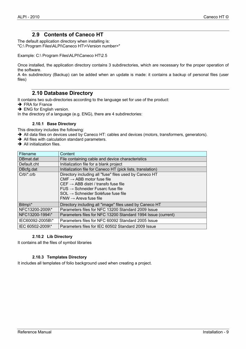
This directory includes the following: All data files on devices used by Caneco HT: cables and devices (motors, transformers, generators). All files with calculation standard parameters. All initialization files. Filename Content DBmat.dat File containing cable and device characteristics Default.cht Initialization file for a blank project DBcfg.dat Initialization file for Caneco HT (pick lists, translation) Crb\*.crb Directory including all "fuse" files used by Caneco HT
CMF → ABB motor fuse file CEF → ABB distri / transfo fuse file FUS → Schneider Fusarc fuse file SOL → Schneider Soléfuse fuse file FNW → Areva fuse file
Bitmp\* Directory including all "image" files used by Caneco HT NFC13200-2009\* Parameters files for NFC 13200 Standard 2009 Issue NFC13200-1994\* Parameters files for NFC 13200 Standard 1994 Issue (current)
IEC60092-2005B\* Parameters files for NFC 60092 Standard 2005 Issue
IEC 60502-2009\* Parameters files for IEC 60502 Standard 2009 Issue
2.10.2 Lib Directory
It contains all the files of symbol libraries
2.10.3 Templates Directory
It includes all templates of folio background used when creating a project.
Caneco HT © ALPI - 2010
10 - Installation Reference Manual
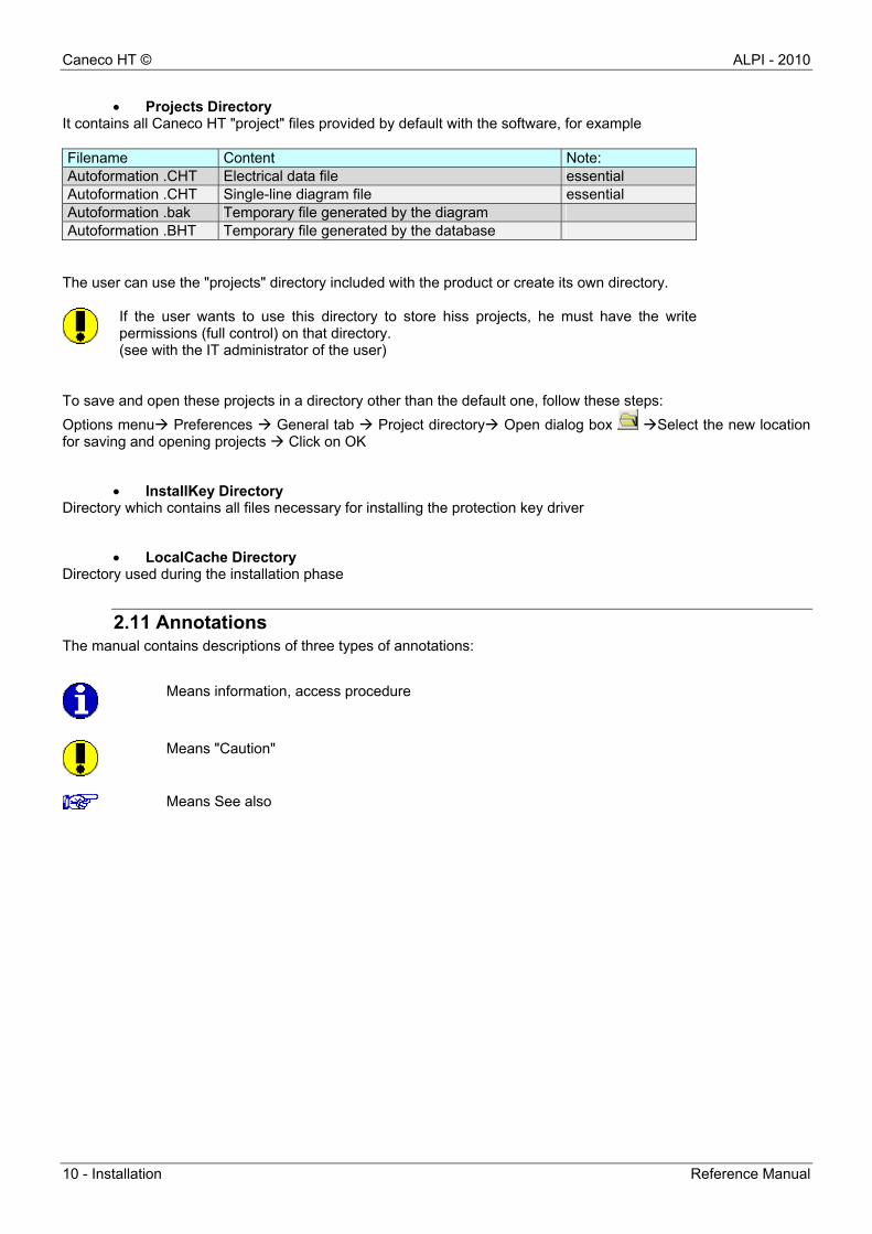
Projects Directory It contains all Caneco HT "project" files provided by default with the software, for example Filename Content Note: Autoformation .CHT Electrical data file essential Autoformation .CHT Single-line diagram file essential Autoformation .bak Temporary file generated by the diagram Autoformation .BHT Temporary file generated by the database
The user can use the "projects" directory included with the product or create its own directory.
If the user wants to use this directory to store hiss projects, he must have the writepermissions (full control) on that directory. (see with the IT administrator of the user)
To save and open these projects in a directory other than the default one, follow these steps:
Options menu Preferences General tab Project directory Open dialog box Select the new location for saving and opening projects Click on OK
InstallKey Directory Directory which contains all files necessary for installing the protection key driver
LocalCache Directory Directory used during the installation phase
2.11 Annotations The manual contains descriptions of three types of annotations:
Means "Caution"
Means See also
Means information, access procedure
ALPI - 2010 Caneco HT ©
Reference Manual Purpose of the Software - Definitions - 11
3 Purpose of the Software - Definitions
3.1 Purpose Caneco HT is a software intended for calculations and diagrams of High Voltage private electrical installation It enables to design an electrical network, i.e.,: Positioning and identifying electrical devices and electric boards Wiring devices by defining links: connections and cables with structural and installation characteristics that can
be selected by the user Determining the network in different operating configurations possible. Caneco HT summarises cable sizing
criteria Determining electrodynamic and thermal constraints for the devices Generating the comprehensive report, conclusion Generate a discrimination report which provides superimposed curves for triggering of protective devices for the
protection area examined (TCC module)
3.2 Description of Caneco HT software The Caneco HT base module consists of two inseparable modules named HV1 and HV2 The HV1 module includes the following: A graphical editor: single-line diagram, with display of devices, data entry and intermediate calculations, display
of results. Libraries of electrical device characteristics: cables, generators, transformers, asynchronous motors, pre-arc
curves of line protection fuses, transformers and motors A cable sizing program according to the standard An single-line diagram export tool under DXF, DWG, WMF formats
The HV2 module includes the following: The algorithm of short-circuit current calculation by partial implementation of the European Standard EN 60909-
0: August 2002 and of Schedule Part 4 of the Standard. It is used to calculate the maximum and minimum short circuit currents in three-phase symmetrical and
asymmetrical three-phase AC networks applicable to meshed systems, non meshed systems, and production groups.
The HV3 module includes the following: Additional drawing features around the modelling diagram of electrical distribution to be calculated: creation of
electrical symbols not present in the base library, graphical construction of a protection plan. The HV4 module enables: To calculate the voltage drops in wiring systems in the following three cases: in steady state, in no-load state, at
motor starting, taking account of the operation or simultaneous or not start-up of other motors. To calculate the operating voltage across the equipment terminals and equipment voltage as a percentage (%) To determine currents required in each link and equipments of the electrical installation, which is prior to
calculation of voltage drops. Calculations are performed regardless of the installation configuration. The HV5 module (Marine Standard) is applicable to electrical installations of ships and mobile and fixed offshore units. This module enables: To calculate the AC short-circuit current anywhere in the system according to IEC 61-363-1 To determine the cable cross-section according to IEC 92-201, IEC 92-202: Installations in ships: System
design and IEC 60092-353: Electrical installation in ships: Choice and installation of electrical cables. The HV6 module which is a foreign languages module, enables: To enter a project by selecting a working language (user interface options: French, English, or German) To generate the calculation report in French, English or German, without changing the language of the user
interface
Caneco HT © ALPI - 2010
12 - Purpose of the Software - Definitions Reference Manual
3.3 Definitions The following definitions are approved:
Links: the term link refers to a set of three-phase overhead lines and underground lines, inductances (resistance neglected) and impedances (values in R and X). The links are regarded as passive elements. Links may be: A connection between two devices: impedance of the link with null length has a zero value An isolated cable An isolated overhead line A transmission overhead line
Devices: a device is an electrical component used in the network to be studied In Caneco HT, they are grouped into several categories according to their function (production, transformation, consumption, limitation or connection) Supplies Incoming feeder of public energy provider (EDF, ...): supply network Synchronous generator Earthing system Zero-sequence generator Transformers Three-phase two-winding transformer Three-phase three-winding transformer Motors Asynchronous motor Synchronous motor Loads Power consumption static load Limiting impedance Boards HV Board: a table is defined as a point (or node), to which one or more links are connected, which can connect producers and users. Boards are typically installed in substations.
3.4 Standards and reference documents NF EN 60909-0: August 2002 Standard for calculating short-circuit currents in three-phase AC systems NFC 13-200: Schedule Part 4: practical calculation of short-circuit currents Gives the values of Iz withstand currents for cables from the IB design current Specifies the design rules
Practical guide UTE 13-205: Resumes NFC 13-200 for the calculation elements

ALPI - 2010 Caneco HT ©
Reference Manual Caneco HT interface - 13
4 Caneco HT interface
4.1 Caneco HT interface overview The Caneco HT user interface is similar to that of most programs running under Windows environment. The menu bar located at the top of the screen provides 7 to 8 menus. The menu commands enable you to directly trigger an action or to display a sub-menu or dialog box The tool bar under this menu bar enables direct access to a command in one of the menus.
Symbols library
Workspace
Menu bar

Caneco HT © ALPI - 2010
14 - Caneco HT interface Reference Manual
4.2 Menu bar Caneco HT has two types of menu bar. It differs depending on whether the user selects within the area of symbols library, or within the area of the workspace
4.2.1 Menu bar of the symbols library area
The menus are:
File The commands which are accessible relate to the creation, recovery, recording and printing of a drawing. Edit Circuit editing commands: cut - copy - paste - insert Modify The commands are used to make changes to objects and text that are in the drawing. Symbol Editing and configuring of the library symbols Display Display mode of the graphical space Options Caneco-HV environment and layer manager configurations Window Standard menu of Windows on drawing window layout Help Help command
4.2.2 Menu bar of the workspace
It includes some menus of the library area with in addition:
Modify The commands are used to make changes to objects and text that are in the drawing. Project: Menu which includes all the modelling tools and calculation options
To view a menu, click on its label on the menu bar. Different commands are displayed
ALPI - 2010 Caneco HT ©
Reference Manual Caneco HT interface - 15
4.3 Menu commands
4.3.1 Pop-up menus
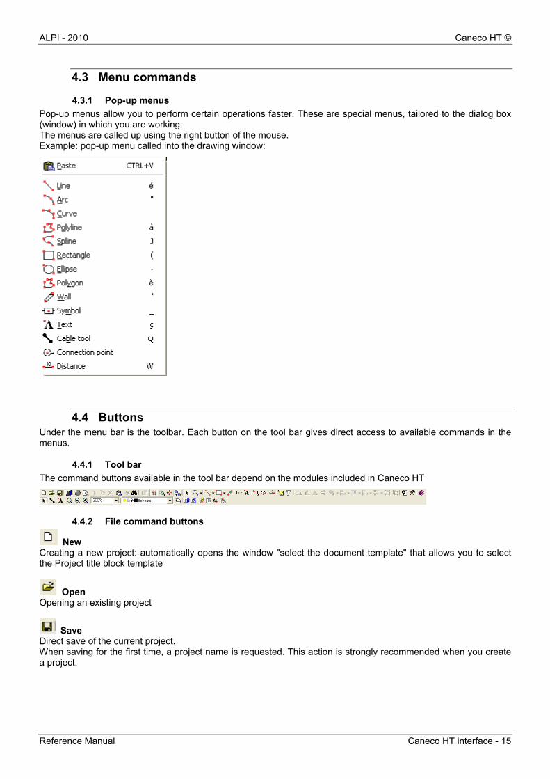
Pop-up menus allow you to perform certain operations faster. These are special menus, tailored to the dialog box (window) in which you are working. The menus are called up using the right button of the mouse. Example: pop-up menu called into the drawing window:
4.4 Buttons Under the menu bar is the toolbar. Each button on the tool bar gives direct access to available commands in the menus.
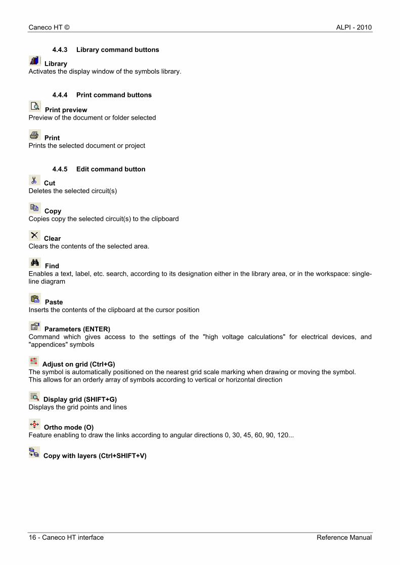
4.4.1 Tool bar
The command buttons available in the tool bar depend on the modules included in Caneco HT
4.4.2 File command buttons
New Creating a new project: automatically opens the window "select the document template" that allows you to select the Project title block template
Open Opening an existing project
Save Direct save of the current project. When saving for the first time, a project name is requested. This action is strongly recommended when you create a project.
Caneco HT © ALPI - 2010
16 - Caneco HT interface Reference Manual
4.4.3 Library command buttons
Library Activates the display window of the symbols library.
4.4.4 Print command buttons
Print preview Preview of the document or folder selected
Print Prints the selected document or project
4.4.5 Edit command button
Cut Deletes the selected circuit(s)
Copy Copies copy the selected circuit(s) to the clipboard
Clear Clears the contents of the selected area.
Find Enables a text, label, etc. search, according to its designation either in the library area, or in the workspace: single-line diagram
Paste Inserts the contents of the clipboard at the cursor position
Parameters (ENTER) Command which gives access to the settings of the "high voltage calculations" for electrical devices, and "appendices" symbols
Adjust on grid (Ctrl+G) The symbol is automatically positioned on the nearest grid scale marking when drawing or moving the symbol. This allows for an orderly array of symbols according to vertical or horizontal direction
Display grid (SHIFT+G) Displays the grid points and lines
Ortho mode (O) Feature enabling to draw the links according to angular directions 0, 30, 45, 60, 90, 120...
Copy with layers (Ctrl+SHIFT+V)
ALPI - 2010 Caneco HT ©
Reference Manual Caneco HT interface - 17
4.4.6 Rotation command buttons
Electrical symbols must be selected beforehand. These features are available with the drawing module.
Rotate right Rotates the selected object 90° clockwise
Rotate left Rotates the selected object 90° anticlockwise
Flip horizontally Flips the selected object horizontally
Flip vertically Flips the selected object vertically
4.4.7 Drawing tools command buttons
Cursor The cursor is used to select or modify an existing graphic object.
Dynamic zoom It allows you to zoom in the workspace. Set the required area by surrounding it with a bounding box.
Zoom factor This factor shall be entered by the user.
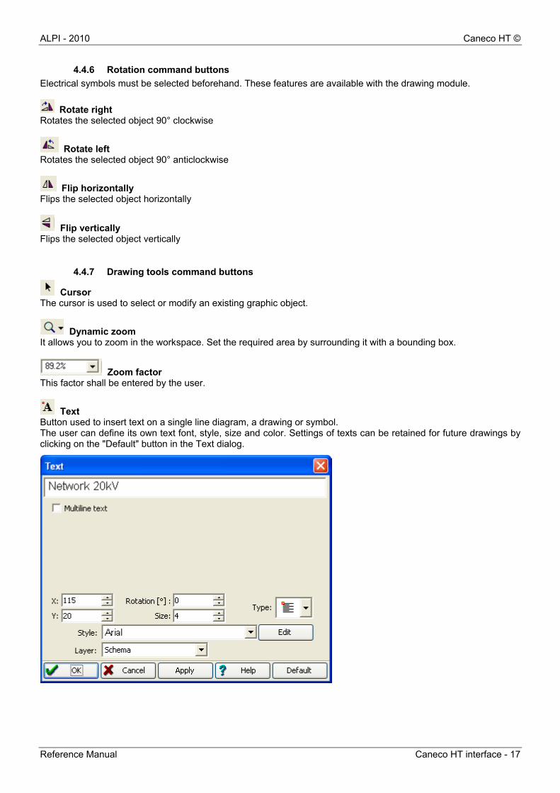
Text Button used to insert text on a single line diagram, a drawing or symbol. The user can define its own text font, style, size and color. Settings of texts can be retained for future drawings by clicking on the "Default" button in the Text dialog.
Caneco HT © ALPI - 2010
18 - Caneco HT interface Reference Manual
Line The Line tool is used to draw a line
Arc The Arc tool is used to draw an arc of a circle.
Polyline Tool used to draw a sequence of straight line segments connected together to create a single object.
Polyline Tool used to draw shapes of the spline type.
Rectangle The Rectangle tool is used to draw a rectangle with or without fill (patterns, colors).
Polygon Closed symbol which consists of straight lines, such as a square, a triangle or a hexagon.
Ellipse The Ellipse tool is used to draw an ellipse with or without fill (patterns, colors).
Layers Open the Layer properties dialog box.
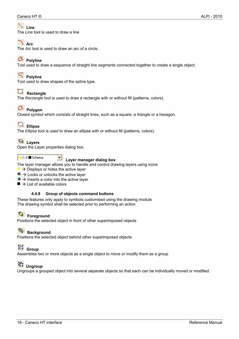
Layer manager dialog box The layer manager allows you to handle and control drawing layers using icons
Displays or hides the active layer Locks or unlocks the active layer Inserts a color into the active layer List of available colors
4.4.8 Group of objects command buttons
These features only apply to symbols customised using the drawing module The drawing symbol shall be selected prior to performing an action
Foreground Positions the selected object in front of other superimposed objects
Background Positions the selected object behind other superimposed objects
Group Assembles two or more objects as a single object to move or modify them as a group
Ungroup Ungroups a grouped object into several separate objects so that each can be individually moved or modified.
ALPI - 2010 Caneco HT ©
Reference Manual Caneco HT interface - 19
4.4.9 Electrical link tool command button
Link This tool allows you to create an electrical link between an electrical symbol and another one: Either a "connection" (zero impedance) or a link (cable and its track) The ALPI site contains an initiation example: Item Caneco HT software
4.4.10 Calculation command button
List of devices Lists by type all devices used in the project.
List of links Lists all simple links (cables) and connections used in the project.
Starting short-circuit current calculations This button starts the calculations of short-circuit currents: per board or on all boards in the system, and according to only 1 operating configuration. It also provides impedances of short-circuit equivalent to boards In addition, it is used to know the individual short-circuit current within each branch which is connected to it
Starting the comprehensive calculation folder It calculates the system at any point and for different patterns of operations selected: short-circuit current calculations, link sizing... The calculation note which is issued, includes detailed network data (list of devices), the patterns of operation and the report on calculations performed
Voltage drop calculation The HV4 module is used to calculate voltage drops at boards or on a point of the system (device terminals) and according to the different types of state: steady, start or no load.

ALPI - 2010 Caneco HT ©
Reference Manual The library area menus - 21
5 The library area menus
5.1 Library area: File menu
5.1.1 General
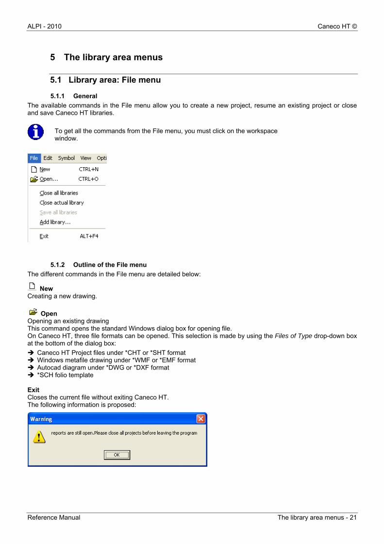
The available commands in the File menu allow you to create a new project, resume an existing project or close and save Caneco HT libraries.
To get all the commands from the File menu, you must click on the workspace window.
5.1.2 Outline of the File menu
The different commands in the File menu are detailed below:
New Creating a new drawing.
Open Opening an existing drawing This command opens the standard Windows dialog box for opening file. On Caneco HT, three file formats can be opened. This selection is made by using the Files of Type drop-down box at the bottom of the dialog box:
Caneco HT Project files under *CHT or *SHT format Windows metafile drawing under *WMF or *EMF format Autocad diagram under *DWG or *DXF format *SCH folio template Exit Closes the current file without exiting Caneco HT. The following information is proposed:

Caneco HT © ALPI - 2010
22 - The library area menus Reference Manual
5.2 Library area: Edit menu
5.2.1 Foreword
Caneco High Voltage uses the general concepts of the Windows environment. The editing commands generally apply to "selected" objects. The objects we can select from High Voltage Caneco are symbols, links or graphic objects. Selecting an object is by left-clicking on the object. Multiple objects can be selected by holding down the Shift key and left-clicking on objects.
Copy Copies the selected area onto the clipboard
Cut Cuts the selected area and places it on the clipboard.
Delete Deletes the contents of the selected area.
Find Searches the symbol in the libraries
ALPI - 2010 Caneco HT ©
Reference Manual The library area menus - 23
5.3 Library area: Symbol menu
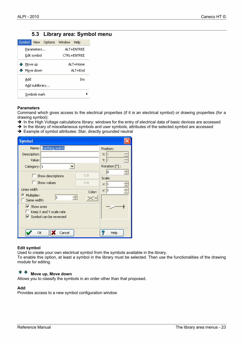
Parameters Command which gives access to the electrical properties (if it is an electrical symbol) or drawing properties (for a drawing symbol): In the High Voltage calculations library: windows for the entry of electrical data of basic devices are accessed In the library of miscellaneous symbols and user symbols, attributes of the selected symbol are accessed Example of symbol attributes: Star, directly grounded neutral
Edit symbol Used to create your own electrical symbol from the symbols available in the library. To enable this option, at least a symbol in the library must be selected. Then use the functionalities of the drawing module for editing.
Move up, Move down Allows you to classify the symbols in an order other than that proposed. Add Provides access to a new symbol configuration window

Caneco HT © ALPI - 2010
24 - The library area menus Reference Manual
Add a sub-library Creates a sub-library in the library already open Example: add a sub-library named "electric pictograms" to the "miscellaneous symbols" library.
1. Select the "miscellaneous symbols" to which you want to add a "sub-library". 2. From the Symbol menu, select add to the sub-library 3. Enter a name such as below: example: "New group"
4. the "sub-library" is displayed as shown below
5.4 Library area: Display menu
Add view Displays the symbol library tree on the workspace area.
ALPI - 2010 Caneco HT ©
Reference Manual The library area menus - 25
5.5 Library area: Option menu
5.5.1 Preferences…
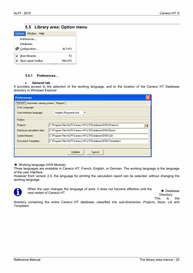
General tab It provides access to the selection of the working language, and to the location of the Caneco HT Database directory in Windows Explorer
Working language (HV6 Module) Three languages are available in Caneco HT: French, English, or German. The working language is the language of the user interface However from version 2.5, the language for printing the calculation report can be selected, without changing the working language.
Database
Directory This is the
directory containing the entire Caneco HT database, classified into sub-directories: Projects, Base, Lib and Templates
When the user changes the language of work, it does not become effective until the next restart of Caneco HT
Caneco HT © ALPI - 2010
26 - The library area menus Reference Manual
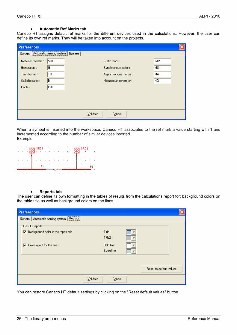
Automatic Ref Marks tab Caneco HT assigns default ref marks for the different devices used in the calculations. However, the user can define its own ref marks. They will be taken into account on the projects.
When a symbol is inserted into the workspace, Caneco HT associates to the ref mark a value starting with 1 and incremented according to the number of similar devices inserted. Example:
Reports tab The user can define its own formatting in the tables of results from the calculations report for: background colors on the table title as well as background colors on the lines.
You can restore Caneco HT default settings by clicking on the "Reset default values" button

ALPI - 2010 Caneco HT ©
Reference Manual The library area menus - 27
5.5.2 Option menu: Database
It provides access to the electrical cables database classified by manufacturer file or UTE file. Each file contains cable families and for each of them we have the electrical characteristics.
Catalog file: Cable families Caneco HT contains a multi-manufacturer cable database: Pirelli, Prysmian, Sagem. It also incorporates in its base cables standard and cables 60092 Marine
Families file: Cable characteristics Cables are classified according to their operating voltage and depending on their type: ALU or CU; unipolar, tripolar or Stranded, PR, PVC or EPR insulant, manufacturing standards
Manufacturer sort option
Sort by family according to manufacturer
Characteristics per cable family

Caneco HT © ALPI - 2010
28 - The library area menus Reference Manual
5.5.3 Option menu: Configuration…
This dialog box has 6 tabs to configure different parameters of the Caneco HT drawing module. Configuration is general and independent of the active drawing
Configuration: Display tab This tab allows you to change the layout of the Caneco HT environment (Interface, Library and Workspace)
Show page breaks: Page breaks can be displayed or hidden on the drawing page to check the framing of this drawing based on the print media. Page breaks are symbolized by red dashes that do not appear on print.
ALPI - 2010 Caneco HT ©
Reference Manual The library area menus - 29
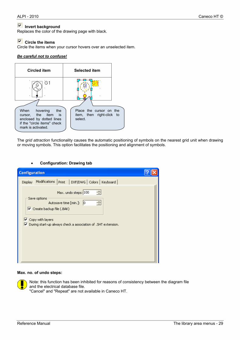
Invert background Replaces the color of the drawing page with black.
Circle the items Circle the items when your cursor hovers over an unselected item. Be careful not to confuse!
Circled item
Selected item
The grid attraction functionality causes the automatic positioning of symbols on the nearest grid unit when drawing or moving symbols. This option facilitates the positioning and alignment of symbols.
Configuration: Drawing tab
Max. no. of undo steps:
Note: this function has been inhibited for reasons of consistency between the diagram fileand the electrical database file. "Cancel" and "Repeat" are not available in Caneco HT.
When hovering the cursor, the item is enclosed by dotted lines if the "circle items" check mark is activated.
Place the cursor on the item, then right-click to select.
Caneco HT © ALPI - 2010
30 - The library area menus Reference Manual
Creating backup file This is a temporary .BAK file which is automatically generated by the diagram
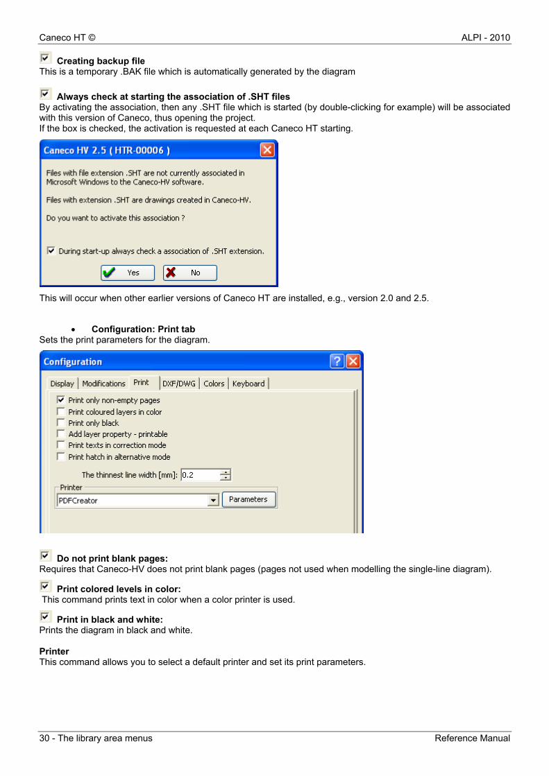
Always check at starting the association of .SHT files By activating the association, then any .SHT file which is started (by double-clicking for example) will be associated with this version of Caneco, thus opening the project. If the box is checked, the activation is requested at each Caneco HT starting.
This will occur when other earlier versions of Caneco HT are installed, e.g., version 2.0 and 2.5.
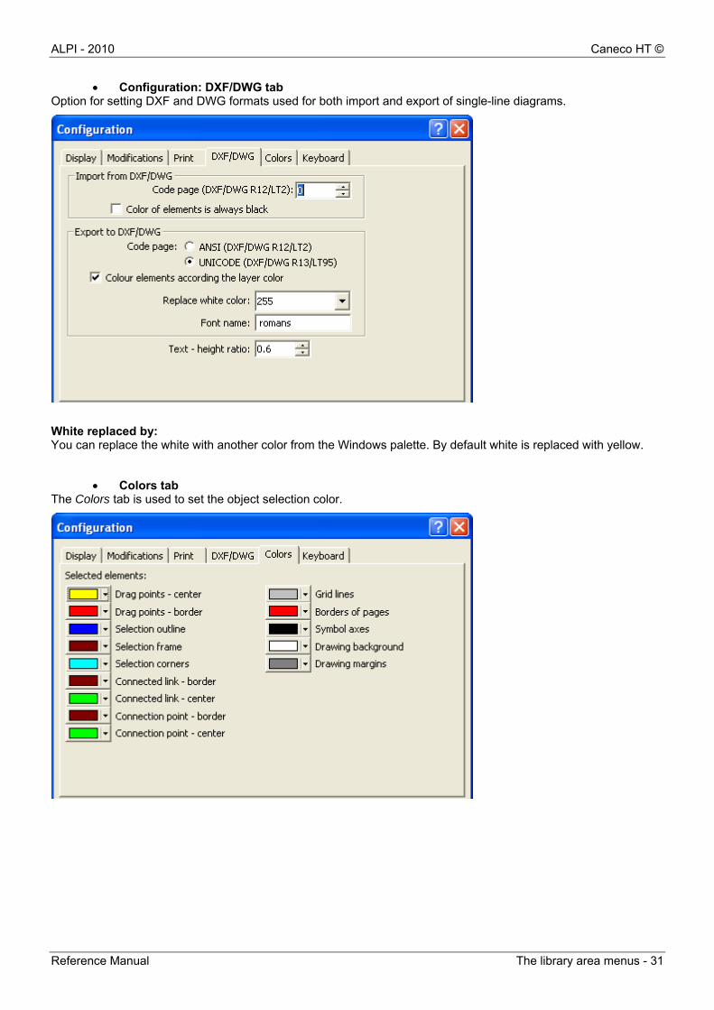
Configuration: Print tab Sets the print parameters for the diagram.
Do not print blank pages: Requires that Caneco-HV does not print blank pages (pages not used when modelling the single-line diagram).
Print colored levels in color: This command prints text in color when a color printer is used.
Print in black and white: Prints the diagram in black and white. Printer This command allows you to select a default printer and set its print parameters.
ALPI - 2010 Caneco HT ©
Reference Manual The library area menus - 31
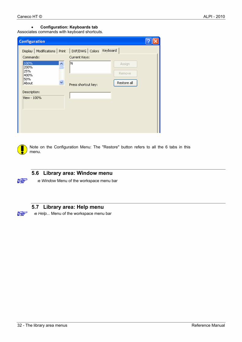
Configuration: DXF/DWG tab Option for setting DXF and DWG formats used for both import and export of single-line diagrams.
White replaced by: You can replace the white with another color from the Windows palette. By default white is replaced with yellow.
Colors tab The Colors tab is used to set the object selection color.
Caneco HT © ALPI - 2010
32 - The library area menus Reference Manual
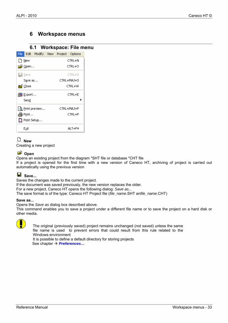
Configuration: Keyboards tab Associates commands with keyboard shortcuts.
Note on the Configuration Menu: The "Restore" button refers to all the 6 tabs in thismenu.
5.6 Library area: Window menu
5.7 Library area: Help menu he Help... Menu of the workspace menu bar
he Window Menu of the workspace menu bar
ALPI - 2010 Caneco HT ©
Reference Manual Workspace menus - 33
6 Workspace menus
6.1 Workspace: File menu
New Creating a new project
Open Opens an existing project from the diagram *SHT file or database *CHT file If a project is opened for the first time with a new version of Caneco HT, archiving of project is carried out automatically using the previous version
Save... Saves the changes made to the current project. If the document was saved previously, the new version replaces the older. For a new project, Caneco HT opens the following dialog: Save as... The save format is of the type: Caneco HT Project file (file_name.SHT anfile_name.CHT)
Save as... Opens the Save as dialog box described above. This command enables you to save a project under a different file name or to save the project on a hard disk or other media.
The original (previously saved) project remains unchanged (not saved) unless the samefile name is used to prevent errors that could result from this rule related to theWindows environment It is possible to define a default directory for storing projects
See chapter Preferences…
Caneco HT © ALPI - 2010
34 - Workspace menus Reference Manual
Close … You cannot exit Caneco HT without closing the documents. Use either the "Close" button from the File menu or the
"Close" command from the toolbar
Once the documents are closed, you can exit Caneco HT using the main button or Exit from the File menu
Export… Exports the current diagram under an image format (wmf, emf, dwg, dxf or bmp) Send … Sends the open project via email
Print preview … The Print Preview feature allows you to preview the diagram to be printed: the page size, orientation (portrait or landscape) and also its margins
Print Setup … Sets the parameters of the Caneco HT diagram: Layers, Type, Attributes, Format, Grid, Print, ...
See below: Diagram parameters
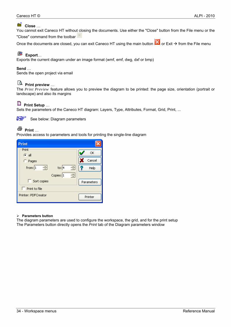
Print … Provides access to parameters and tools for printing the single-line diagram
Parameters button The diagram parameters are used to configure the workspace, the grid, and for the print setup The Parameters button directly opens the Print tab of the Diagram parameters window
ALPI - 2010 Caneco HT ©
Reference Manual Workspace menus - 35
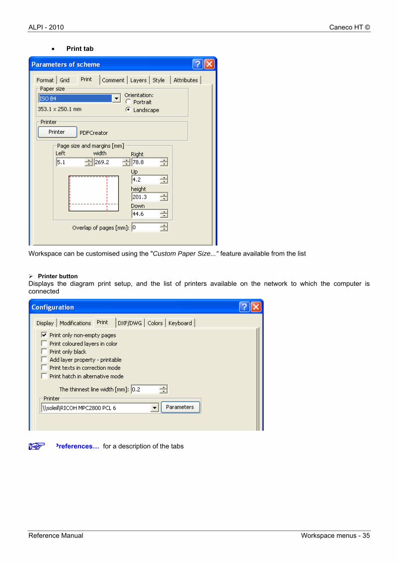
Print tab
Workspace can be customised using the "Custom Paper Size..." feature available from the list
Printer button Displays the diagram print setup, and the list of printers available on the network to which the computer is connected
Preferences… for a description of the tabs

Caneco HT © ALPI - 2010
36 - Workspace menus Reference Manual
Page size and margins Features used to adjust the worksheet based on graphical content and to adapt it to the size of the printer used. Page overlapping (mm) When the drawing page exceeds the size of the printer, this parameter will define the page overlapping value (to help pasting the diagram) The page overlapping is represented by red dashes which show the drawing page breaks based on the size (printer or user) of the print media that the user himself has selected on this tab.
If the marks of page overlapping do not appear on the drawing sheet, go to Option Setup Display menu and check the Show page breaks case.
Format tab Configuration tab of the workspace
Workspace size (Format): 23 sheet formats -A0, A1, A2, A3, A4, A5, BO, B1, B2, B3, B4, B5 with an additional function to customize the size of the workspace. It is in the list of formats named User format. Size of the sheet is entered using the width and height in mm fields. The origin of the drawing can be defined on the X and Y axis: X min and X max, Y min and Y max. The print scale of the diagram is set as a percentage (%).
ALPI - 2010 Caneco HT ©
Reference Manual Workspace menus - 37
Grid tab
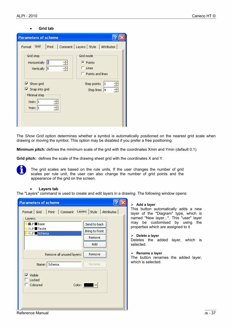
The Show Grid option determines whether a symbol is automatically positioned on the nearest grid scale when drawing or moving the symbol. This option may be disabled if you prefer a free positioning. Minimum pitch: defines the minimum scale of the grid with the coordinates Xmin and Ymin (default 0.1) Grid pitch: defines the scale of the drawing sheet grid with the coordinates X and Y.
The grid scales are based on the rule units. If the user changes the number of gridscales per rule unit, the user can also change the number of grid points and theappearance of the grid on the screen.
Layers tab The "Layers" command is used to create and edit layers in a drawing. The following window opens:
Add a layer This button automatically adds a new layer of the "Diagram" type, which is named "New layer...". This "user" layer may be customised by using the properties which are assigned to it Delete a layer Deletes the added layer, which is selected. Rename a layer The button renames the added layer, which is selected.
Caneco HT © ALPI - 2010
38 - Workspace menus Reference Manual
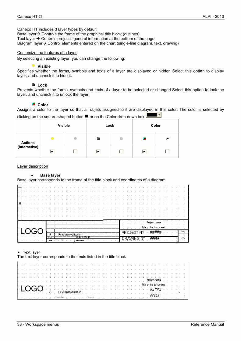
Caneco HT includes 3 layer types by default: Base layer Controls the frame of the graphical title block (outlines) Text layer Controls project's general information at the bottom of the page Diagram layer Control elements entered on the chart (single-line diagram, text, drawing) Customize the features of a layer:
By selecting an existing layer, you can change the following:
Visible Specifies whether the forms, symbols and texts of a layer are displayed or hidden Select this option to display layer, and uncheck it to hide it.
Lock Prevents whether the forms, symbols and texts of a layer to be selected or changed Select this option to lock the layer, and uncheck it to unlock the layer.
Color Assigns a color to the layer so that all objets assigned to it are displayed in this color. The color is selected by
clicking on the square-shaped button or on the Color drop-down box
Visible
Lock Color
Actions
(interactive)
Layer description
Base layer Base layer corresponds to the frame of the title block and coordinates of a diagram
Text layer The text layer corresponds to the texts listed in the title block
ALPI - 2010 Caneco HT ©
Reference Manual Workspace menus - 39
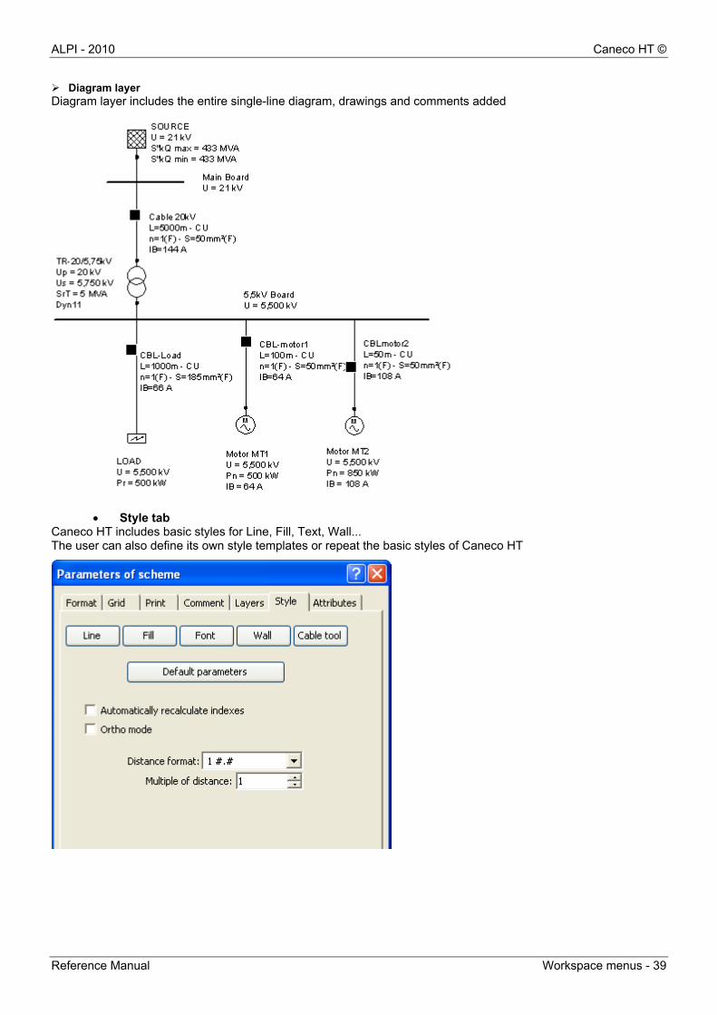
Diagram layer Diagram layer includes the entire single-line diagram, drawings and comments added
Style tab Caneco HT includes basic styles for Line, Fill, Text, Wall... The user can also define its own style templates or repeat the basic styles of Caneco HT
Caneco HT © ALPI - 2010
40 - Workspace menus Reference Manual
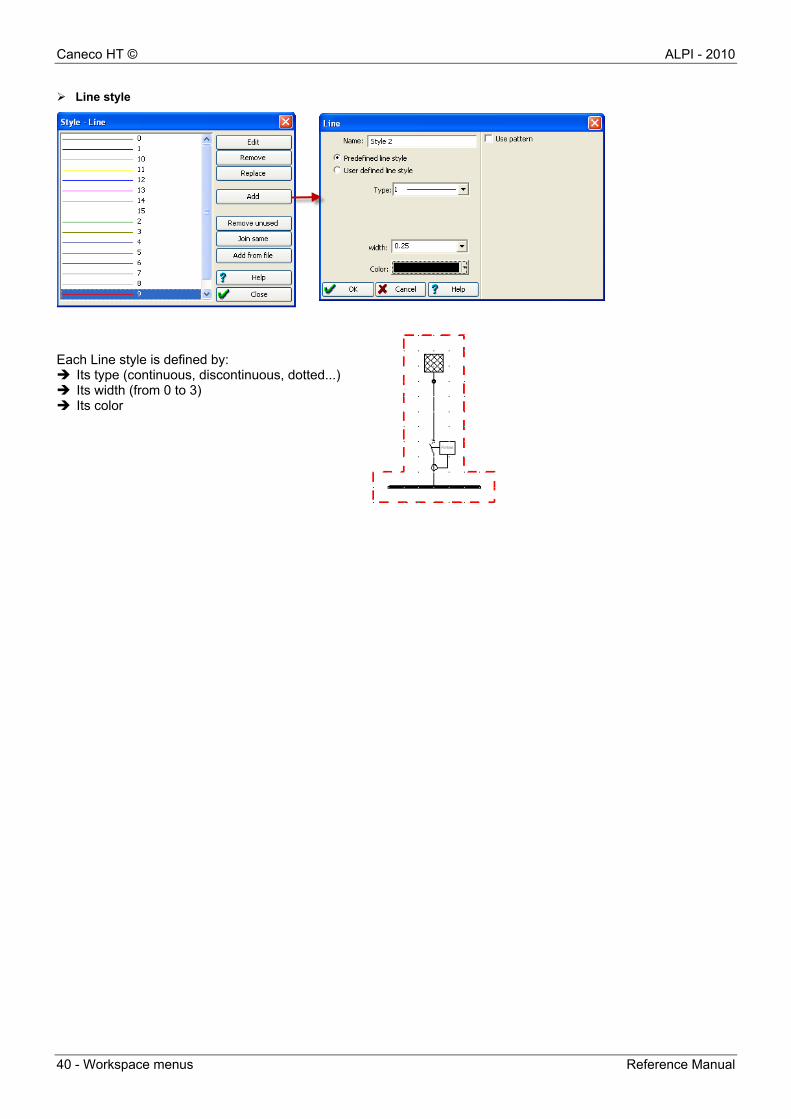
Line style
Each Line style is defined by: Its type (continuous, discontinuous, dotted...) Its width (from 0 to 3) Its color

ALPI - 2010 Caneco HT ©
Reference Manual Workspace menus - 41
Fill style
The Fill style is defined by: Its fill color (background) Its hatching styles (21 styles) Its hatching color Text style (Font) These are styles of text and comment that can be inserted into the diagram
The Text style is defined by: Its font Its size Its color Its effects
Note: When defining a protection plan, it is recommended not to use the fill background (or otherwise use a white background) in order to identify devices and protections for the discrimination study.
Caneco HT © ALPI - 2010
42 - Workspace menus Reference Manual
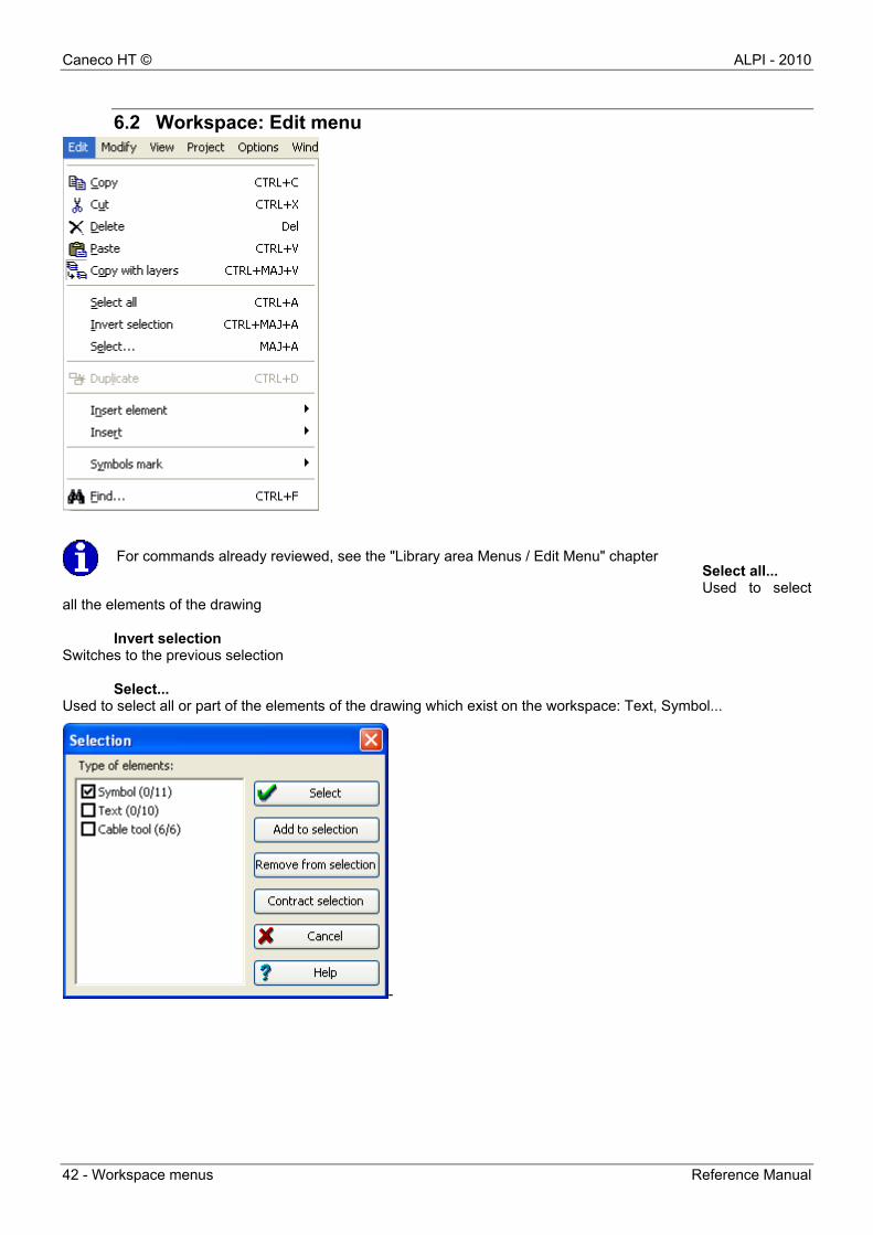
6.2 Workspace: Edit menu
Select all... Used to select
all the elements of the drawing
Invert selection Switches to the previous selection
Select... Used to select all or part of the elements of the drawing which exist on the workspace: Text, Symbol...
-
For commands already reviewed, see the "Library area Menus / Edit Menu" chapter
ALPI - 2010 Caneco HT ©
Reference Manual Workspace menus - 43
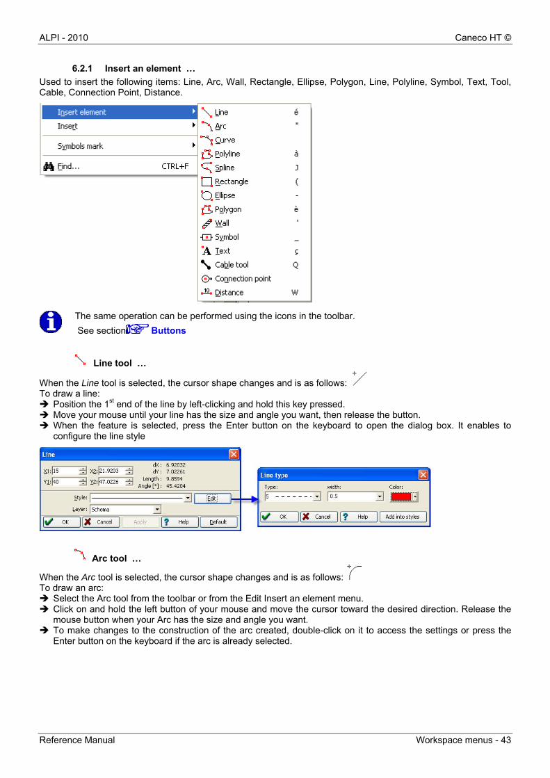
6.2.1 Insert an element …
Used to insert the following items: Line, Arc, Wall, Rectangle, Ellipse, Polygon, Line, Polyline, Symbol, Text, Tool, Cable, Connection Point, Distance.
The same operation can be performed using the icons in the toolbar.
See section Buttons
Line tool …
When the Line tool is selected, the cursor shape changes and is as follows: To draw a line: Position the 1st end of the line by left-clicking and hold this key pressed. Move your mouse until your line has the size and angle you want, then release the button. When the feature is selected, press the Enter button on the keyboard to open the dialog box. It enables to
configure the line style
Arc tool …
When the Arc tool is selected, the cursor shape changes and is as follows: To draw an arc: Select the Arc tool from the toolbar or from the Edit Insert an element menu. Click on and hold the left button of your mouse and move the cursor toward the desired direction. Release the
mouse button when your Arc has the size and angle you want. To make changes to the construction of the arc created, double-click on it to access the settings or press the
Enter button on the keyboard if the arc is already selected.
Caneco HT © ALPI - 2010
44 - Workspace menus Reference Manual
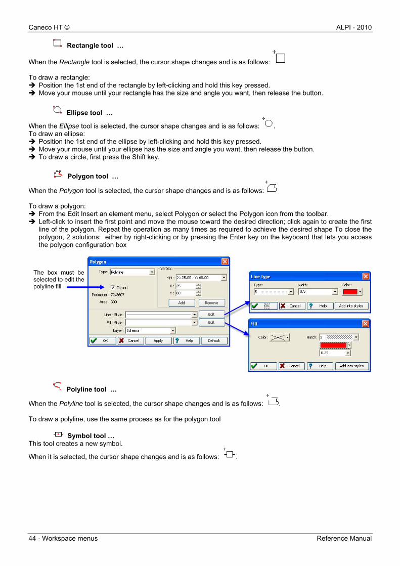
Rectangle tool …
When the Rectangle tool is selected, the cursor shape changes and is as follows: To draw a rectangle: Position the 1st end of the rectangle by left-clicking and hold this key pressed. Move your mouse until your rectangle has the size and angle you want, then release the button.
Ellipse tool …
When the Ellipse tool is selected, the cursor shape changes and is as follows: . To draw an ellipse: Position the 1st end of the ellipse by left-clicking and hold this key pressed. Move your mouse until your ellipse has the size and angle you want, then release the button. To draw a circle, first press the Shift key.
Polygon tool …
When the Polygon tool is selected, the cursor shape changes and is as follows: To draw a polygon: From the Edit Insert an element menu, select Polygon or select the Polygon icon from the toolbar. Left-click to insert the first point and move the mouse toward the desired direction; click again to create the first
line of the polygon. Repeat the operation as many times as required to achieve the desired shape To close the polygon, 2 solutions: either by right-clicking or by pressing the Enter key on the keyboard that lets you access the polygon configuration box
Polyline tool …
When the Polyline tool is selected, the cursor shape changes and is as follows: . To draw a polyline, use the same process as for the polygon tool
Symbol tool … This tool creates a new symbol.
When it is selected, the cursor shape changes and is as follows: .
The box must be selected to edit the polyline fill
ALPI - 2010 Caneco HT ©
Reference Manual Workspace menus - 45
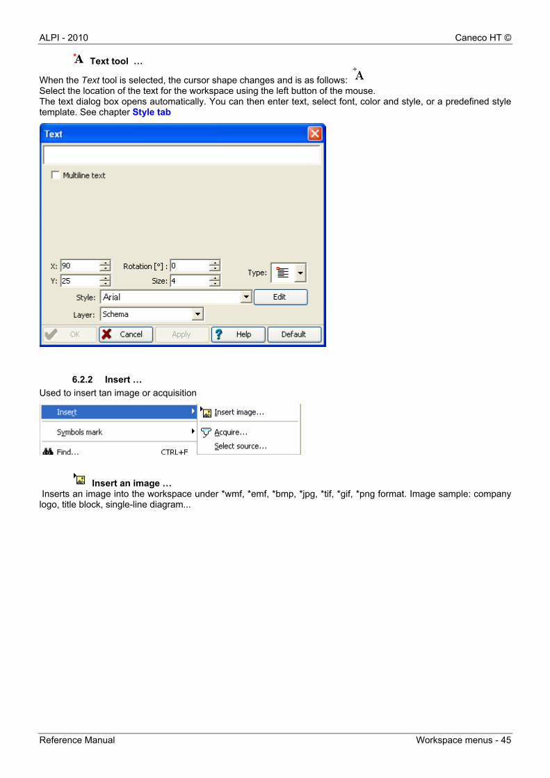
Text tool …
When the Text tool is selected, the cursor shape changes and is as follows: Select the location of the text for the workspace using the left button of the mouse. The text dialog box opens automatically. You can then enter text, select font, color and style, or a predefined style template. See chapter Style tab
6.2.2 Insert …
Used to insert tan image or acquisition
Insert an image … Inserts an image into the workspace under *wmf, *emf, *bmp, *jpg, *tif, *gif, *png format. Image sample: company logo, title block, single-line diagram...
Caneco HT © ALPI - 2010
46 - Workspace menus Reference Manual
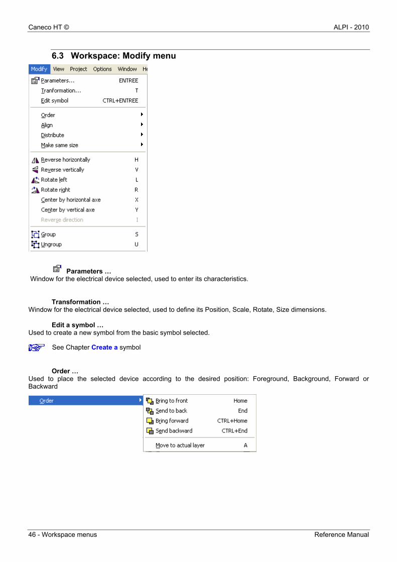
6.3 Workspace: Modify menu
Parameters … Window for the electrical device selected, used to enter its characteristics.
Transformation … Window for the electrical device selected, used to define its Position, Scale, Rotate, Size dimensions.
Edit a symbol … Used to create a new symbol from the basic symbol selected.
Order … Used to place the selected device according to the desired position: Foreground, Background, Forward or Backward
See Chapter Create a symbol
ALPI - 2010 Caneco HT ©
Reference Manual Workspace menus - 47
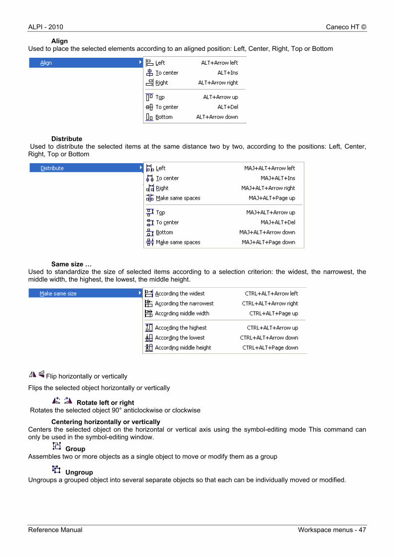
Align Used to place the selected elements according to an aligned position: Left, Center, Right, Top or Bottom
Distribute
Used to distribute the selected items at the same distance two by two, according to the positions: Left, Center, Right, Top or Bottom
Same size …
Used to standardize the size of selected items according to a selection criterion: the widest, the narrowest, the middle width, the highest, the lowest, the middle height.
Flip horizontally or vertically
Flips the selected object horizontally or vertically
Rotate left or right Rotates the selected object 90° anticlockwise or clockwise
Centering horizontally or vertically Centers the selected object on the horizontal or vertical axis using the symbol-editing mode This command can only be used in the symbol-editing window.
Group Assembles two or more objects as a single object to move or modify them as a group
Ungroup Ungroups a grouped object into several separate objects so that each can be individually moved or modified.
Caneco HT © ALPI - 2010
48 - Workspace menus Reference Manual
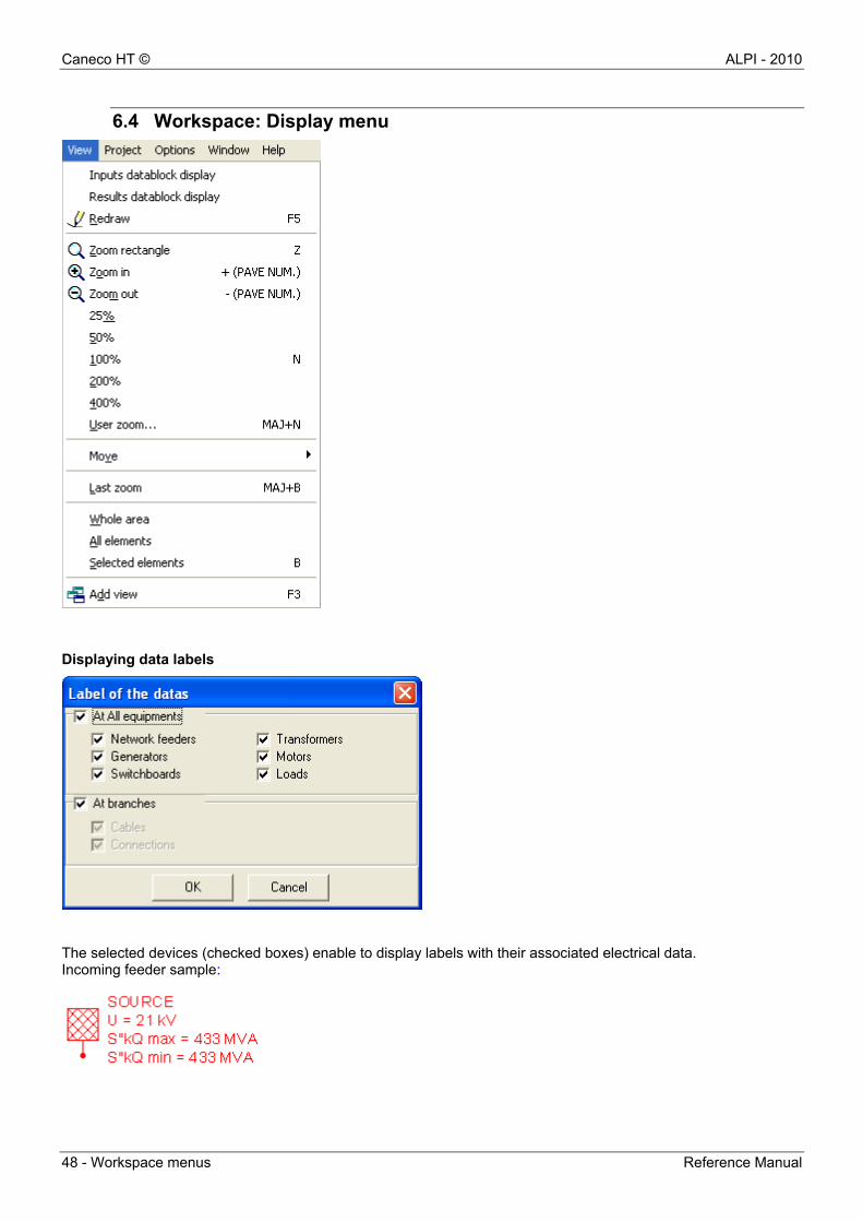
6.4 Workspace: Display menu
Displaying data labels
The selected devices (checked boxes) enable to display labels with their associated electrical data. Incoming feeder sample:
ALPI - 2010 Caneco HT ©
Reference Manual Workspace menus - 49
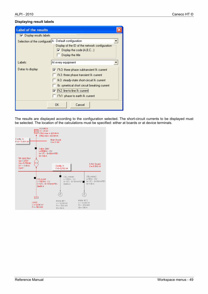
Displaying result labels
The results are displayed according to the configuration selected. The short-circuit currents to be displayed must be selected. The location of the calculations must be specified: either at boards or at device terminals.
Caneco HT © ALPI - 2010
50 - Workspace menus Reference Manual
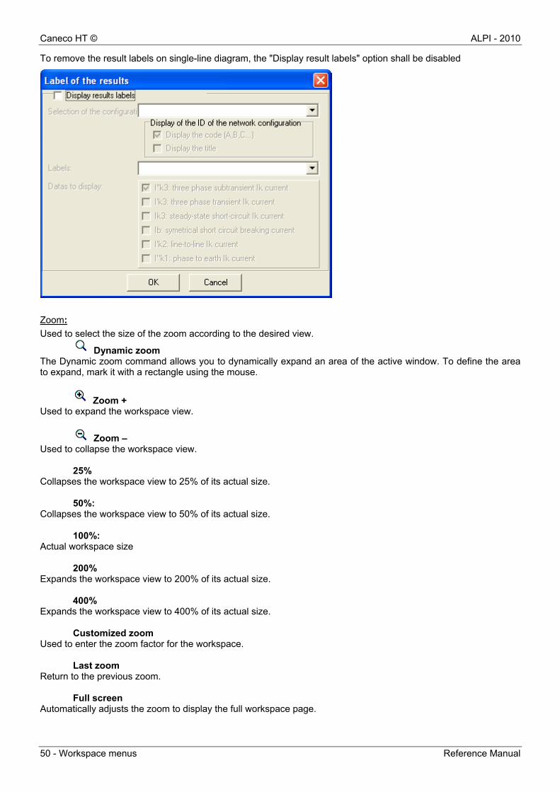
To remove the result labels on single-line diagram, the "Display result labels" option shall be disabled
Zoom:
Used to select the size of the zoom according to the desired view.
Dynamic zoom The Dynamic zoom command allows you to dynamically expand an area of the active window. To define the area to expand, mark it with a rectangle using the mouse.
Zoom + Used to expand the workspace view.
Zoom – Used to collapse the workspace view.
25% Collapses the workspace view to 25% of its actual size.
50%: Collapses the workspace view to 50% of its actual size.
100%: Actual workspace size
200% Expands the workspace view to 200% of its actual size.
400% Expands the workspace view to 400% of its actual size.
Customized zoom Used to enter the zoom factor for the workspace.
Last zoom Return to the previous zoom.
Full screen Automatically adjusts the zoom to display the full workspace page.
ALPI - 2010 Caneco HT ©
Reference Manual Workspace menus - 51
All elements Automatically adjusts the zoom to display all the elements on the workspace.
Selected elements Automatically adjusts the zoom according to selected items in the workspace. Keyboard shortcuts for using the zoom
Zoom + Press the < + > key on the numeric keypad to zoom out.
Zoom –
Press the < - > key on the numeric keypad to zoom in.
Zoom 100% Simultaneously press the Ctrl and N keys to get the actual size.
Zooming selected elements
Simultaneously press the Ctrl and B keys to zoom selected items.
Caneco HT © ALPI - 2010
52 - Workspace menus Reference Manual
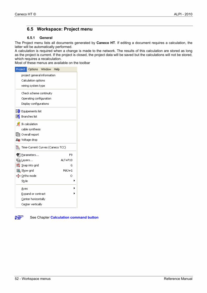
6.5 Workspace: Project menu
6.5.1 General
The Project menu lists all documents generated by Caneco HT. If editing a document requires a calculation, the latter will be automatically performed. A calculation is required when a change is made to the network. The results of this calculation are stored as long as the project is current. If the project is closed, the project data will be saved but the calculations will not be stored, which requires a recalculation. Most of these menus are available on the toolbar
See Chapter Calculation command button
ALPI - 2010 Caneco HT ©
Reference Manual Workspace menus - 53
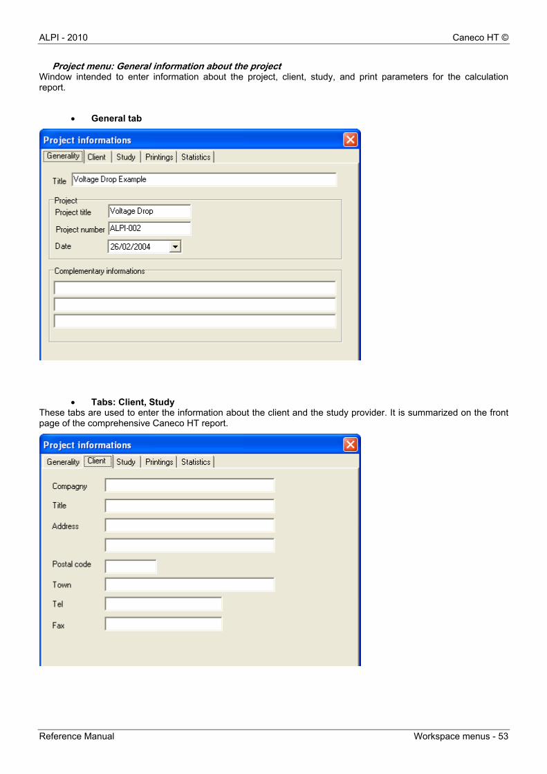
Project menu: General information about the project Window intended to enter information about the project, client, study, and print parameters for the calculation report.
General tab
Tabs: Client, Study These tabs are used to enter the information about the client and the study provider. It is summarized on the front page of the comprehensive Caneco HT report.
Caneco HT © ALPI - 2010
54 - Workspace menus Reference Manual
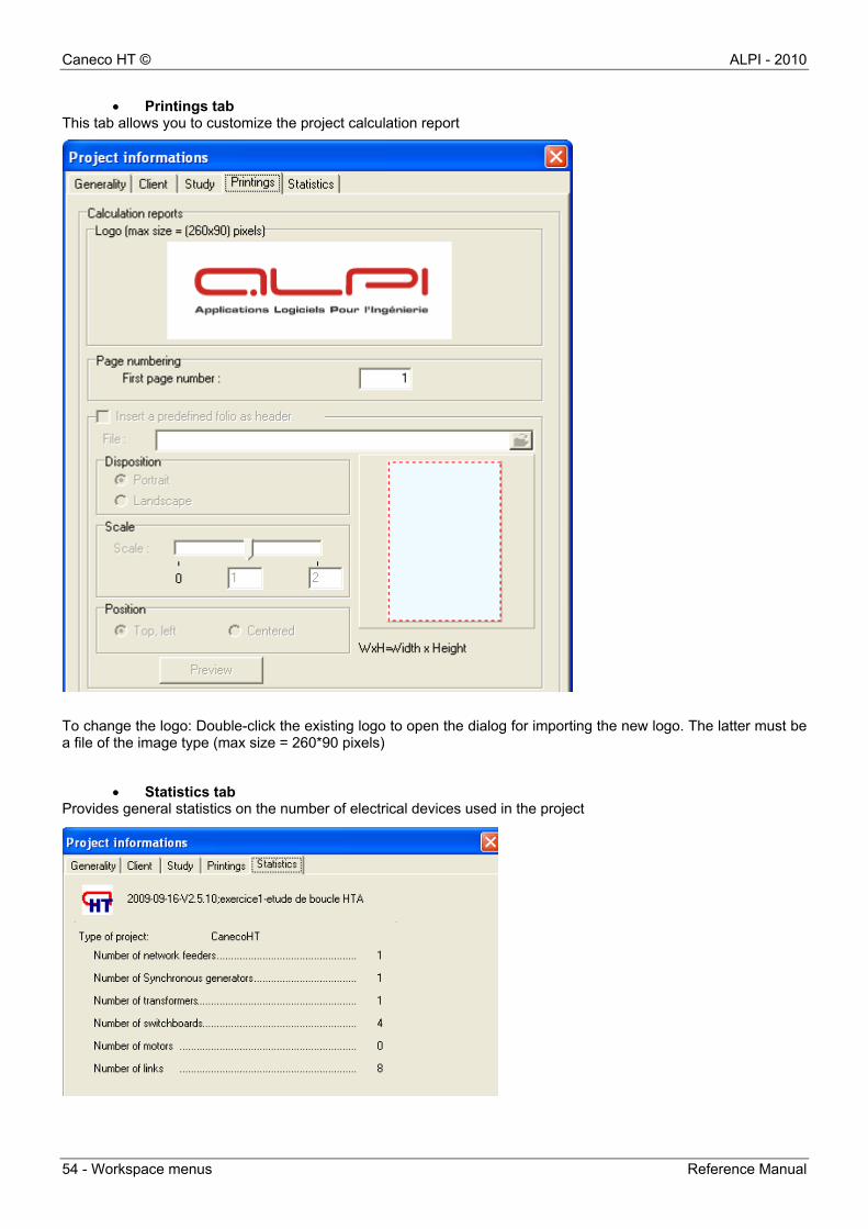
Printings tab This tab allows you to customize the project calculation report
To change the logo: Double-click the existing logo to open the dialog for importing the new logo. The latter must be a file of the image type (max size = 260*90 pixels)
Statistics tab Provides general statistics on the number of electrical devices used in the project
ALPI - 2010 Caneco HT ©
Reference Manual Workspace menus - 55
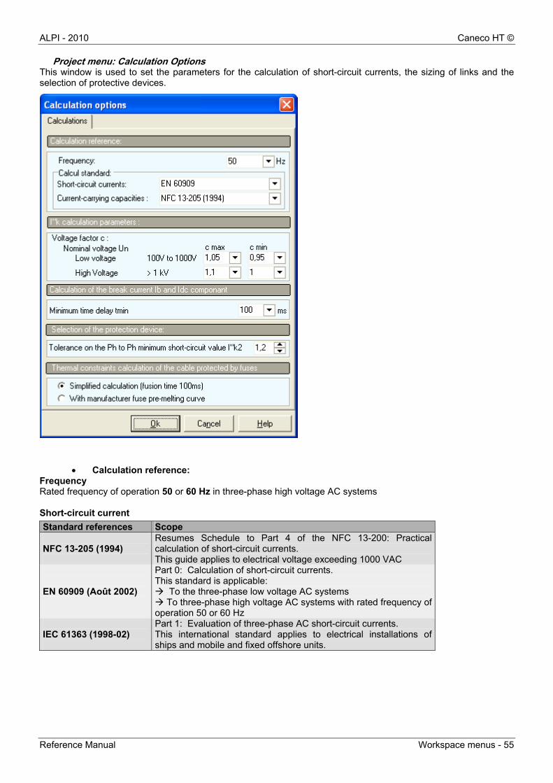
Project menu: Calculation Options This window is used to set the parameters for the calculation of short-circuit currents, the sizing of links and the selection of protective devices.
Calculation reference: Frequency Rated frequency of operation 50 or 60 Hz in three-phase high voltage AC systems Short-circuit current
Standard references Scope NFC 13-205 (1994)
Resumes Schedule to Part 4 of the NFC 13-200: Practical calculation of short-circuit currents. This guide applies to electrical voltage exceeding 1000 VAC
EN 60909 (Août 2002)
Part 0: Calculation of short-circuit currents. This standard is applicable: To the three-phase low voltage AC systems To three-phase high voltage AC systems with rated frequency of operation 50 or 60 Hz
IEC 61363 (1998-02)
Part 1: Evaluation of three-phase AC short-circuit currents. This international standard applies to electrical installations of ships and mobile and fixed offshore units.
Caneco HT © ALPI - 2010
56 - Workspace menus Reference Manual
Withstand current
Standard references Scope NFC 13-200 (1987)
This standard applies to installations powered by alternating current at a rated voltage no less than 1000 V and up to 63 kV, with frequency not greater than 100 Hz .
NFC 13-200 (2009)
This standard applies to installations powered by alternating current at a rated voltage no less than 1000 V and up to 245 kV, the preferred frequency being 50 Hz and 60 Hz (current).
IEC 60092-352
Electrical installations in ships - Part 352: Choice and installation of electrical cables
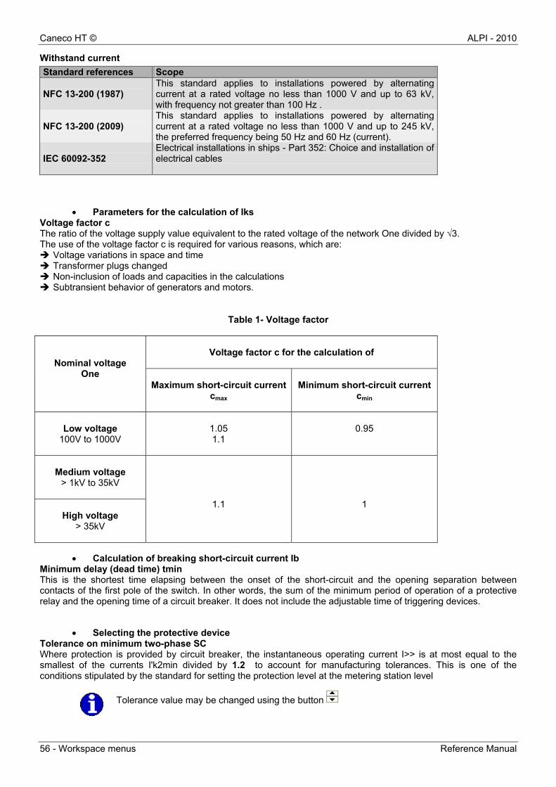
Parameters for the calculation of Iks Voltage factor c The ratio of the voltage supply value equivalent to the rated voltage of the network One divided by √3. The use of the voltage factor c is required for various reasons, which are: Voltage variations in space and time Transformer plugs changed Non-inclusion of loads and capacities in the calculations Subtransient behavior of generators and motors.
Table 1- Voltage factor
Voltage factor c for the calculation of
Nominal voltage One
Maximum short-circuit currentcmax
Minimum short-circuit current
cmin
Low voltage
100V to 1000V
1.05 1.1
0.95
Medium voltage
> 1kV to 35kV
High voltage > 35kV
1.1
1
Calculation of breaking short-circuit current Ib Minimum delay (dead time) tmin This is the shortest time elapsing between the onset of the short-circuit and the opening separation between contacts of the first pole of the switch. In other words, the sum of the minimum period of operation of a protective relay and the opening time of a circuit breaker. It does not include the adjustable time of triggering devices.
Selecting the protective device Tolerance on minimum two-phase SC Where protection is provided by circuit breaker, the instantaneous operating current I>> is at most equal to the smallest of the currents I'k2min divided by 1.2 to account for manufacturing tolerances. This is one of the conditions stipulated by the standard for setting the protection level at the metering station level
Tolerance value may be changed using the button
ALPI - 2010 Caneco HT ©
Reference Manual Workspace menus - 57
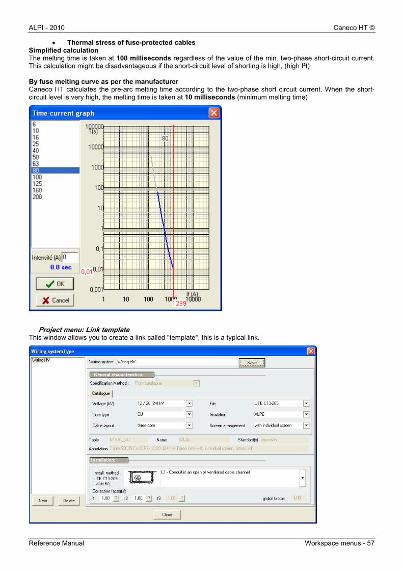
Thermal stress of fuse-protected cables Simplified calculation The melting time is taken at 100 milliseconds regardless of the value of the min. two-phase short-circuit current. This calculation might be disadvantageous if the short-circuit level of shorting is high, (high I²t) By fuse melting curve as per the manufacturer Caneco HT calculates the pre-arc melting time according to the two-phase short circuit current. When the short-circuit level is very high, the melting time is taken at 10 milliseconds (minimum melting time)
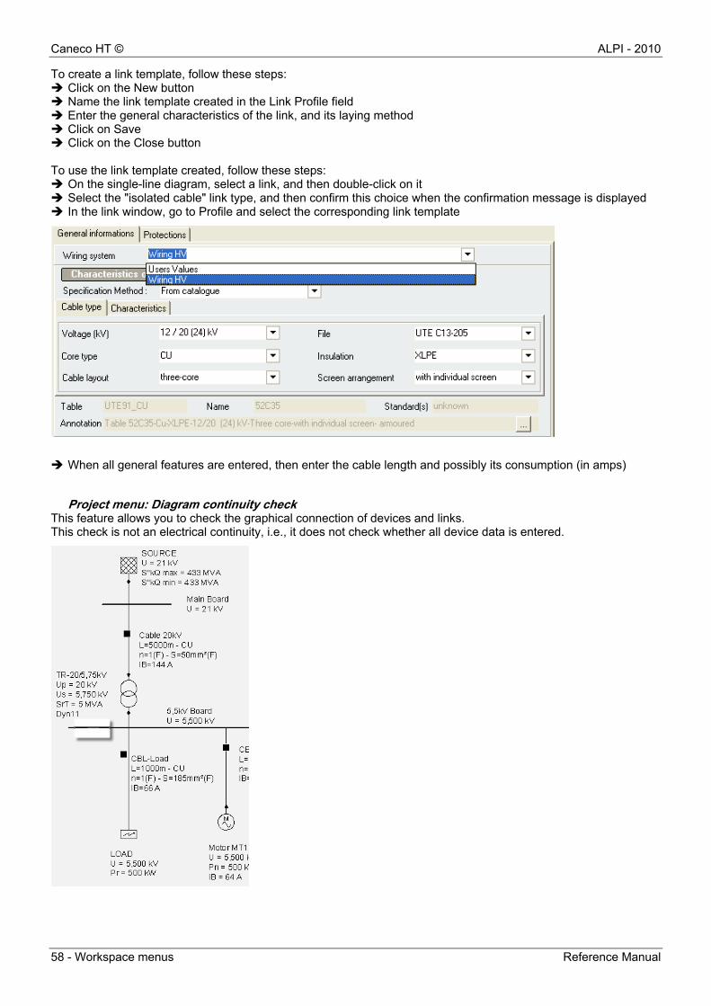
Project menu: Link template This window allows you to create a link called "template", this is a typical link.
Caneco HT © ALPI - 2010
58 - Workspace menus Reference Manual
To create a link template, follow these steps: Click on the New button Name the link template created in the Link Profile field Enter the general characteristics of the link, and its laying method Click on Save Click on the Close button To use the link template created, follow these steps: On the single-line diagram, select a link, and then double-click on it Select the "isolated cable" link type, and then confirm this choice when the confirmation message is displayed In the link window, go to Profile and select the corresponding link template
When all general features are entered, then enter the cable length and possibly its consumption (in amps)
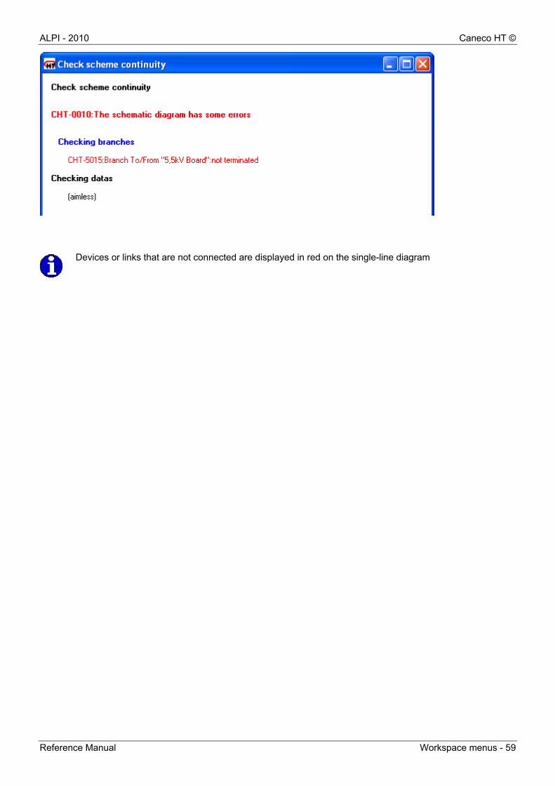
Project menu: Diagram continuity check This feature allows you to check the graphical connection of devices and links. This check is not an electrical continuity, i.e., it does not check whether all device data is entered.
ALPI - 2010 Caneco HT ©
Reference Manual Workspace menus - 59
Devices or links that are not connected are displayed in red on the single-line diagram

Caneco HT © ALPI - 2010
60 - Workspace menus Reference Manual
Project menu: Operating configuration This feature allows you to define the different operating modes for an electrical installation: normal, degraded, cogeneration, open loop, closed loop...
A link called Ref mark includes a beginning Ref mark and an ending Ref mark. For a given configuration, that link is either enabled or disabled.
When the box corresponding to the link is checked , this means that the link is enabled for this given configuration.
When the box corresponding to the link is unchecked , this means that the link is disabled for this given configuration. To enable or disable a link, there are 3 options From the Operating configuration window: Double-click on the box to enable or disable the link Or select the checkbox, and then right-click to display the pop-up menu and select or deselect
From the Link window: On the single-line diagram, double-click on the link to display its window. Caneco HT specifies on this window
the various configurations created which enable or disable this link by simply clicking on the corresponding box
ALPI - 2010 Caneco HT ©
Reference Manual Workspace menus - 61
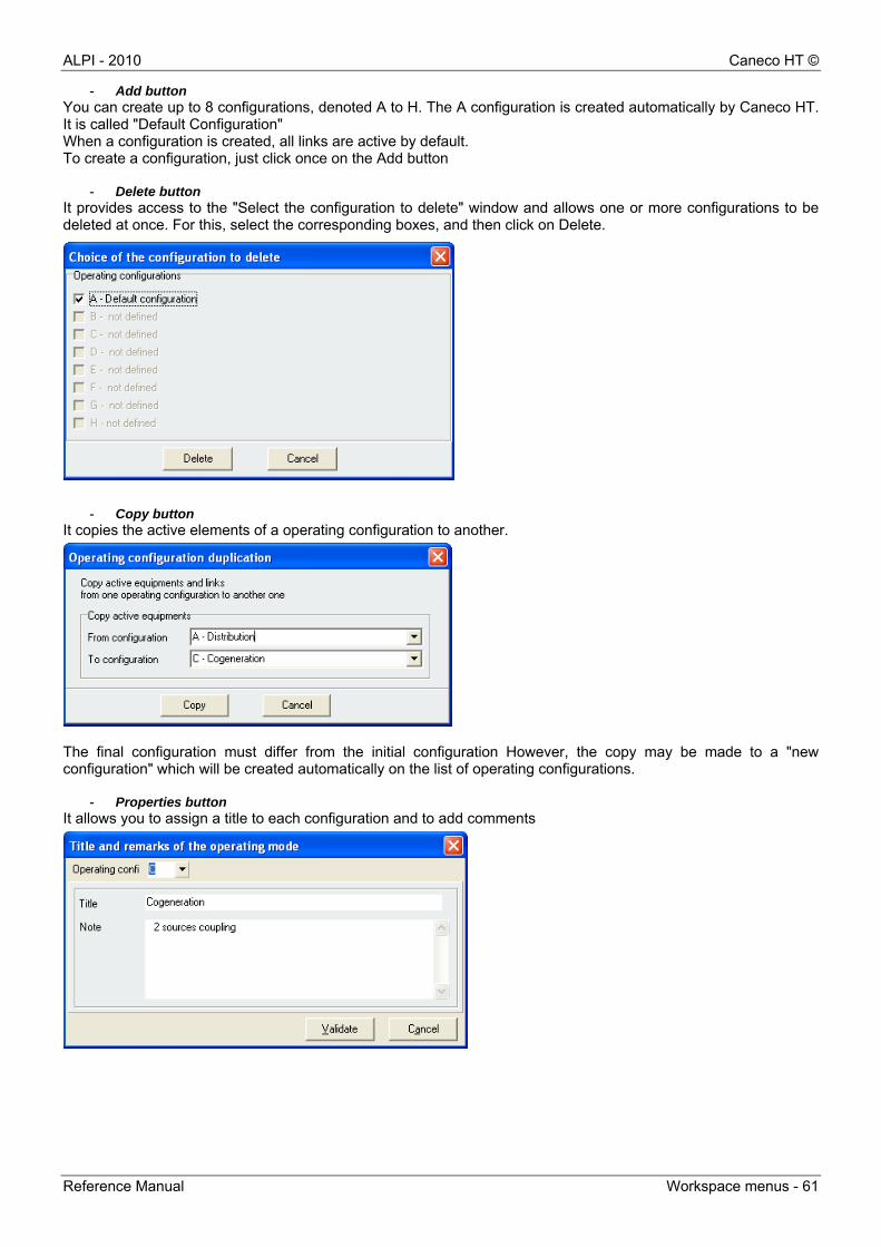
- Add button You can create up to 8 configurations, denoted A to H. The A configuration is created automatically by Caneco HT. It is called "Default Configuration" When a configuration is created, all links are active by default. To create a configuration, just click once on the Add button
- Delete button It provides access to the "Select the configuration to delete" window and allows one or more configurations to be deleted at once. For this, select the corresponding boxes, and then click on Delete.
- Copy button
It copies the active elements of a operating configuration to another.
The final configuration must differ from the initial configuration However, the copy may be made to a "new configuration" which will be created automatically on the list of operating configurations.
- Properties button It allows you to assign a title to each configuration and to add comments
Caneco HT © ALPI - 2010
62 - Workspace menus Reference Manual
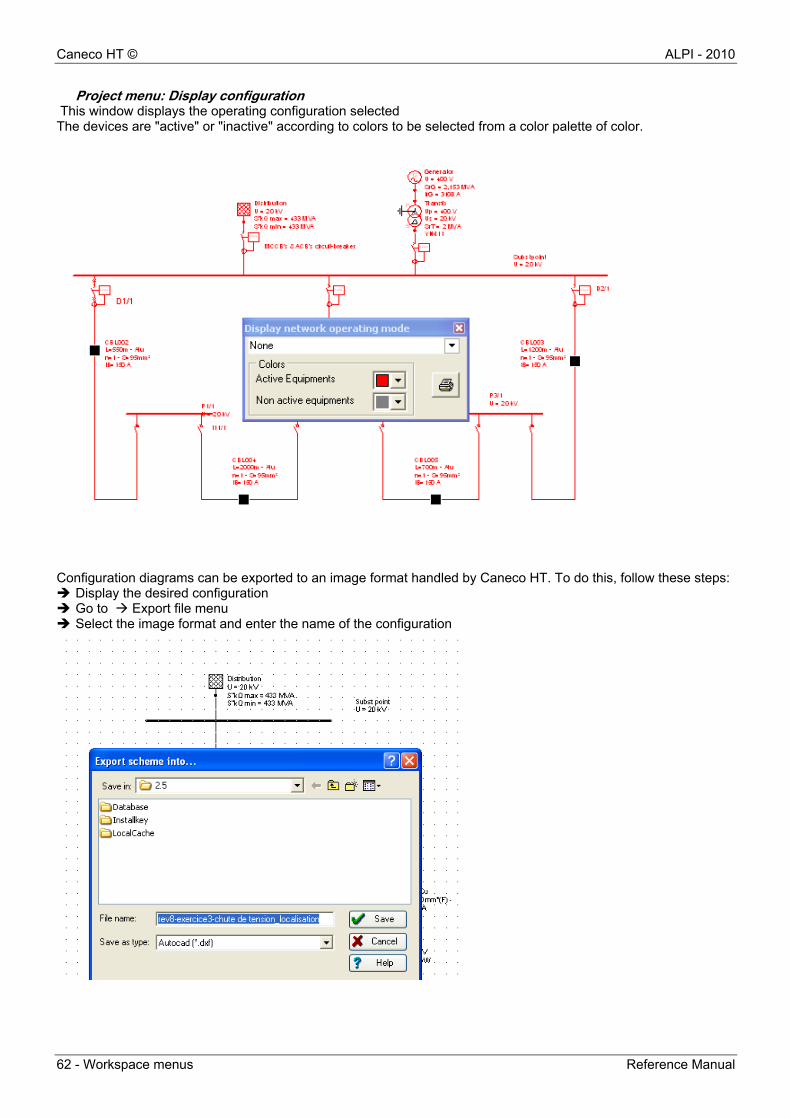
Project menu: Display configuration This window displays the operating configuration selected The devices are "active" or "inactive" according to colors to be selected from a color palette of color.
Configuration diagrams can be exported to an image format handled by Caneco HT. To do this, follow these steps: Display the desired configuration Go to Export file menu Select the image format and enter the name of the configuration
ALPI - 2010 Caneco HT ©
Reference Manual Workspace menus - 63
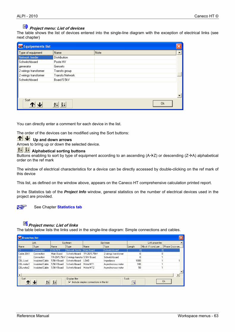
Project menu: List of devices The table shows the list of devices entered into the single-line diagram with the exception of electrical links (see next chapter)
You can directly enter a comment for each device in the list. The order of the devices can be modified using the Sort buttons:
Up and down arrows Arrows to bring up or down the selected device.
Alphabetical sorting buttons Buttons enabling to sort by type of equipment according to an ascending (AZ) or descending (ZA) alphabetical order on the ref mark The window of electrical characteristics for a device can be directly accessed by double-clicking on the ref mark of this device This list, as defined on the window above, appears on the Caneco HT comprehensive calculation printed report. In the Statistics tab of the Project Info window, general statistics on the number of electrical devices used in the project are provided.
Project menu: List of links The table below lists the links used in the single-line diagram: Simple connections and cables.
See Chapter Statistics tab
Caneco HT © ALPI - 2010
64 - Workspace menus Reference Manual
The order of the links can be modified using the Sort buttons:
Up and down arrows Arrows to bring up or down the selected link.
Alphabetical sorting buttons Buttons enabling to sort by type of link according to an ascending (AZ) or descending (ZA) alphabetical order on the ref mark The display filter allows you to include or not the simple connections in the list. The Tools feature allows you to export the list of links and these electrical characteristics to an Excel file. To display from the window above, the window of an electrical link with its electrical characteristics, just double-click on the row for that link. The Statistics tab of the Project Info window, provides general statistics on the number of electrical links used in the project.
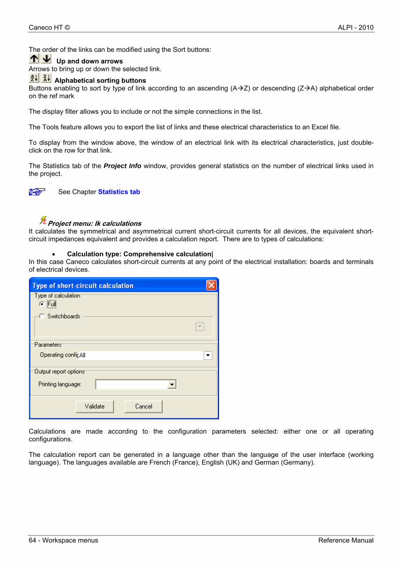
Project menu: Ik calculations It calculates the symmetrical and asymmetrical current short-circuit currents for all devices, the equivalent short-circuit impedances equivalent and provides a calculation report. There are to types of calculations:
Calculation type: Comprehensive calculation| In this case Caneco calculates short-circuit currents at any point of the electrical installation: boards and terminals of electrical devices.
Calculations are made according to the configuration parameters selected: either one or all operating configurations. The calculation report can be generated in a language other than the language of the user interface (working language). The languages available are French (France), English (UK) and German (Germany).
See Chapter Statistics tab
ALPI - 2010 Caneco HT ©
Reference Manual Workspace menus - 65
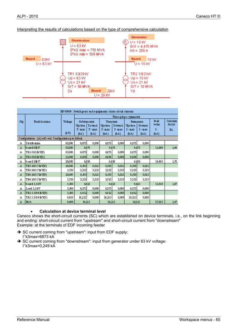
Interpreting the results of calculations based on the type of comprehensive calculation
Calculation at device terminal level Caneco shows the short-circuit currents (SC) which are established on device terminals, i.e., on the link beginning and ending: short-circuit current from "upstream" and short-circuit current from "downstream" Example: at the terminals of EDF incoming feeder
SC current coming from "upstream": input from EDF supply: I’’k3max=6873 kA
SC current coming from "downstream": input from generator under 63 kV voltage: I’’k3max=0,249 kA
Board
DistributionGenerator
Board
Board
Caneco HT © ALPI - 2010
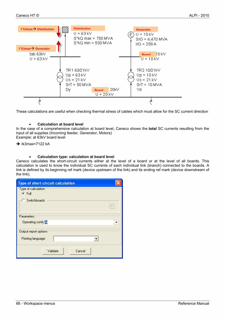
66 - Workspace menus Reference Manual
These calculations are useful when checking thermal stress of cables which must allow for the SC current direction
Calculation at board level In the case of a comprehensive calculation at board level, Caneco shows the total SC currents resulting from the input of all supplies (Incoming feeder, Generator, Motors) Example: at 63kV board level
Ik3max=7122 kA
Calculation type: calculation at board level Caneco calculates the short-circuit currents either at the level of a board or at the level of all boards. This calculation is used to know the individual SC currents of each individual link (branch) connected to the boards. A link is defined by its beginning ref mark (device upstream of the link) and its ending ref mark (device downstream of the link).
Distribution GeneratorI‘’k3max Distribution
I‘’k3max Generator
Board
Board

ALPI - 2010 Caneco HT ©
Reference Manual Workspace menus - 67
Interpreting the results of calculations based on the type of calculation at board level Exemple: at 63 kV board level
Project menu: Summary of cables It allows summarising cables according to two sizing criteria: withstand current and thermal stress.
Caneco HT calculates or checks the cable cross-section according to the selected configurations and provides a comprehensive cable list based on the worst cases. Example: calculation according to the normative practical guide.
I’k3max (Distribution- Board 63 kV) = 6873 kA
I’k3max (Board 63 kV – TR1) = 0,249 kA
Board
Board
Distribution Generator

Caneco HT © ALPI - 2010
68 - Workspace menus Reference Manual
Caneco HT checks link conformity according to both normative criteria. If the number of parallel conductors and the cross-section are forced, Caneco specifies it by associating the letter F.
Example Link CBL13 [Board 5.5kV - 5.5kV load]: SPH (mm²) = 120 F
Cross-section calculation for a cable according to the withstand current criterion This is the first sizing criterion for cables. The current which is used to determine the cross-section depends on the design current in the conduit and on the laying requirements
The reduction factor depends on the laying method standard. Example: Laying method F: Laying on cable tray → fr = 1 Laying method H: Enclosed trunkings →fr = 0,9
Ambiant temperature
Design current
Cable grouping
Ground resistivity
Reduction factor
Number of parallel Cross-section derived
from boards 52C Practical guide standard
ALPI - 2010 Caneco HT ©
Reference Manual Workspace menus - 69
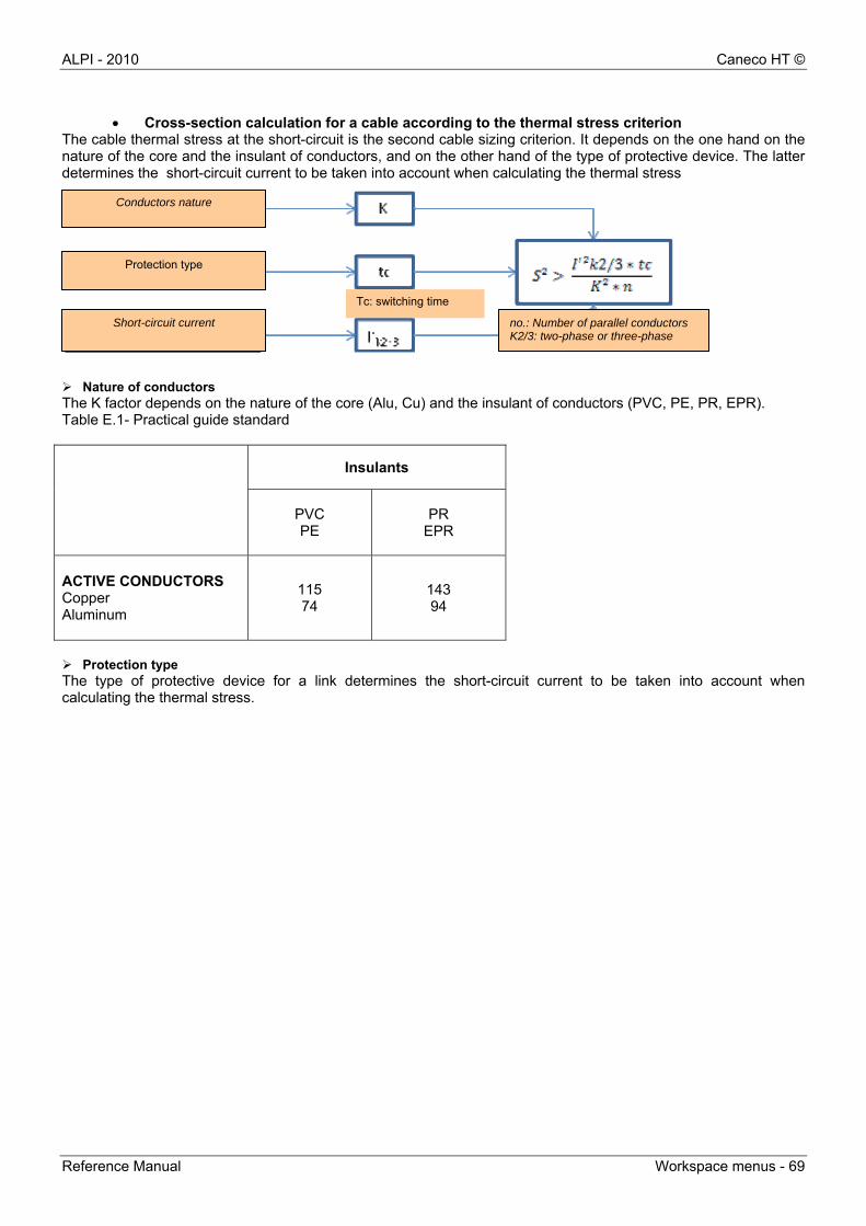
Cross-section calculation for a cable according to the thermal stress criterion The cable thermal stress at the short-circuit is the second cable sizing criterion. It depends on the one hand on the nature of the core and the insulant of conductors, and on the other hand of the type of protective device. The latter determines the short-circuit current to be taken into account when calculating the thermal stress
Nature of conductors The K factor depends on the nature of the core (Alu, Cu) and the insulant of conductors (PVC, PE, PR, EPR). Table E.1- Practical guide standard
Insulants
PVC PE
PR EPR
ACTIVE CONDUCTORS Copper Aluminum
115 74
143 94
Protection type The type of protective device for a link determines the short-circuit current to be taken into account when calculating the thermal stress.
Conductors nature
Protection type
Short-circuit current
Tc: switching time
no.: Number of parallel conductors K2/3: two-phase or three-phase
Caneco HT © ALPI - 2010
70 - Workspace menus Reference Manual
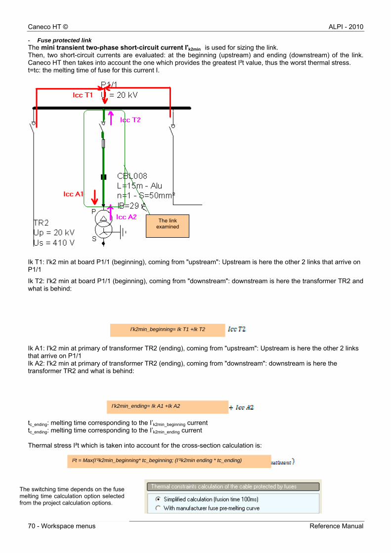
- Fuse protected link The mini transient two-phase short-circuit current I'k2min is used for sizing the link. Then, two short-circuit currents are evaluated: at the beginning (upstream) and ending (downstream) of the link. Caneco HT then takes into account the one which provides the greatest I²t value, thus the worst thermal stress. t=tc: the melting time of fuse for this current I.
Ik T1: I'k2 min at board P1/1 (beginning), coming from "upstream": Upstream is here the other 2 links that arrive on P1/1
Ik T2: I'k2 min at board P1/1 (beginning), coming from "downstream": downstream is here the transformer TR2 and what is behind:
Ik A1: I'k2 min at primary of transformer TR2 (ending), coming from "upstream": Upstream is here the other 2 links that arrive on P1/1 Ik A2: I'k2 min at primary of transformer TR2 (ending), coming from "downstream": downstream is here the transformer TR2 and what is behind:
tc_ending: melting time corresponding to the I’k2min_beginning current tc_ending: melting time corresponding to the I’k2min_ending current Thermal stress I²t which is taken into account for the cross-section calculation is:
The switching time depends on the fuse melting time calculation option selected from the project calculation options.
The link examined
I’k2min_beginniI’k2min_beginning= Ik T1 +Ik T2
I’k2min_ending= Ik A1 +Ik A2
I²t = Max(I’²k2min_beginning* tc_beginning; (I’²k2min ending * tc_ending)
ALPI - 2010 Caneco HT ©
Reference Manual Workspace menus - 71
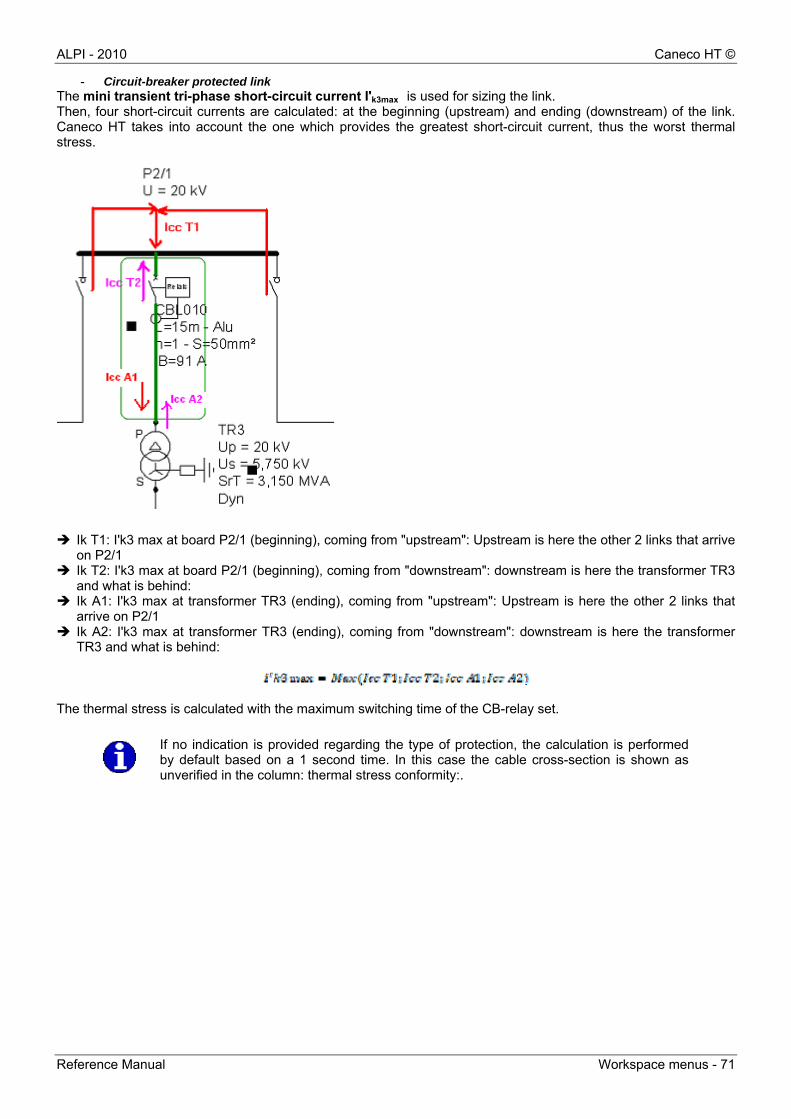
- Circuit-breaker protected link The mini transient tri-phase short-circuit current I'k3max is used for sizing the link. Then, four short-circuit currents are calculated: at the beginning (upstream) and ending (downstream) of the link. Caneco HT takes into account the one which provides the greatest short-circuit current, thus the worst thermal stress.
Ik T1: I'k3 max at board P2/1 (beginning), coming from "upstream": Upstream is here the other 2 links that arrive
on P2/1 Ik T2: I'k3 max at board P2/1 (beginning), coming from "downstream": downstream is here the transformer TR3
and what is behind: Ik A1: I'k3 max at transformer TR3 (ending), coming from "upstream": Upstream is here the other 2 links that
arrive on P2/1 Ik A2: I'k3 max at transformer TR3 (ending), coming from "downstream": downstream is here the transformer
TR3 and what is behind:
The thermal stress is calculated with the maximum switching time of the CB-relay set.
If no indication is provided regarding the type of protection, the calculation is performedby default based on a 1 second time. In this case the cable cross-section is shown as unverified in the column: thermal stress conformity:.
Caneco HT © ALPI - 2010
72 - Workspace menus Reference Manual
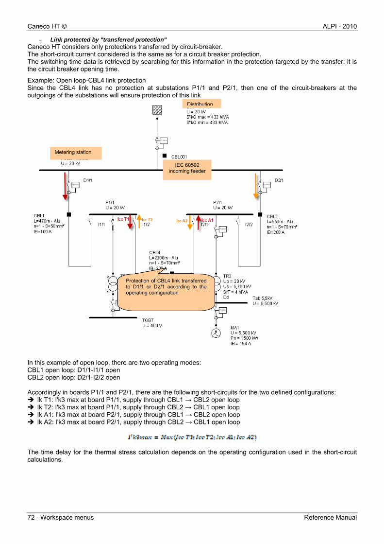
- Link protected by "transferred protection" Caneco HT considers only protections transferred by circuit-breaker. The short-circuit current considered is the same as for a circuit breaker protection. The switching time data is retrieved by searching for this information in the protection targeted by the transfer: it is the circuit breaker opening time.
Example: Open loop-CBL4 link protection Since the CBL4 link has no protection at substations P1/1 and P2/1, then one of the circuit-breakers at the outgoings of the substations will ensure protection of this link
In this example of open loop, there are two operating modes: CBL1 open loop: D1/1-I1/1 open CBL2 open loop: D2/1-I2/2 open Accordingly in boards P1/1 and P2/1, there are the following short-circuits for the two defined configurations: Ik T1: I'k3 max at board P1/1, supply through CBL1 → CBL2 open loop Ik T2: I'k3 max at board P1/1, supply through CBL2 → CBL1 open loop Ik A1: I'k3 max at board P2/1, supply through CBL1 → CBL2 open loop Ik A2: I'k3 max at board P2/1, supply through CBL2 → CBL1 open loop
The time delay for the thermal stress calculation depends on the operating configuration used in the short-circuit calculations.
Metering station
IEC 60502 incoming feeder
Distribution
Protection of CBL4 link transferred to D1/1 or D2/1 according to the operating configuration
ALPI - 2010 Caneco HT ©
Reference Manual Workspace menus - 73
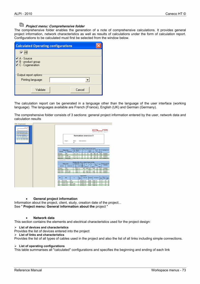
Project menu: Comprehensive folder The comprehensive folder enables the generation of a note of comprehensive calculations. It provides general project information, network characteristics as well as results of calculations under the form of calculation report. Configurations to be calculated must first be selected from the window below.
The calculation report can be generated in a language other than the language of the user interface (working language). The languages available are French (France), English (UK) and German (Germany). The comprehensive folder consists of 3 sections: general project information entered by the user, network data and calculation results
General project information Information about the project, client, study, creation date of the project... See " Project menu: General information about the project "
Network data This section contains the elements and electrical characteristics used for the project design:
List of devices and characteristics Provides the list of devices entered into the project List of links and characteristics Provides the list of all types of cables used in the project and also the list of all links including simple connections. List of operating configurations This table summarises all "calculated" configurations and specifies the beginning and ending of each link
Caneco HT © ALPI - 2010
74 - Workspace menus Reference Manual
Calculation results Calculation results include short-circuit calculation and cable summary according to the different sizing criteria.
Tables of short-circuit currents Two types of SC currents are calculated by Caneco HT: symmetrical SC currents (three-phase calculations) and asymmetrical SC currents (zero-sequence calculations according to symmetrical components). These "comprehensive" calculations are made at all boards and for all the configurations selected
Summary of cables Caneco HT sizes links according to two normative criteria: withstand current and thermal stress. Caneco then provides a list of cables and the cross-sections selected for the criterion and the worst configurations.
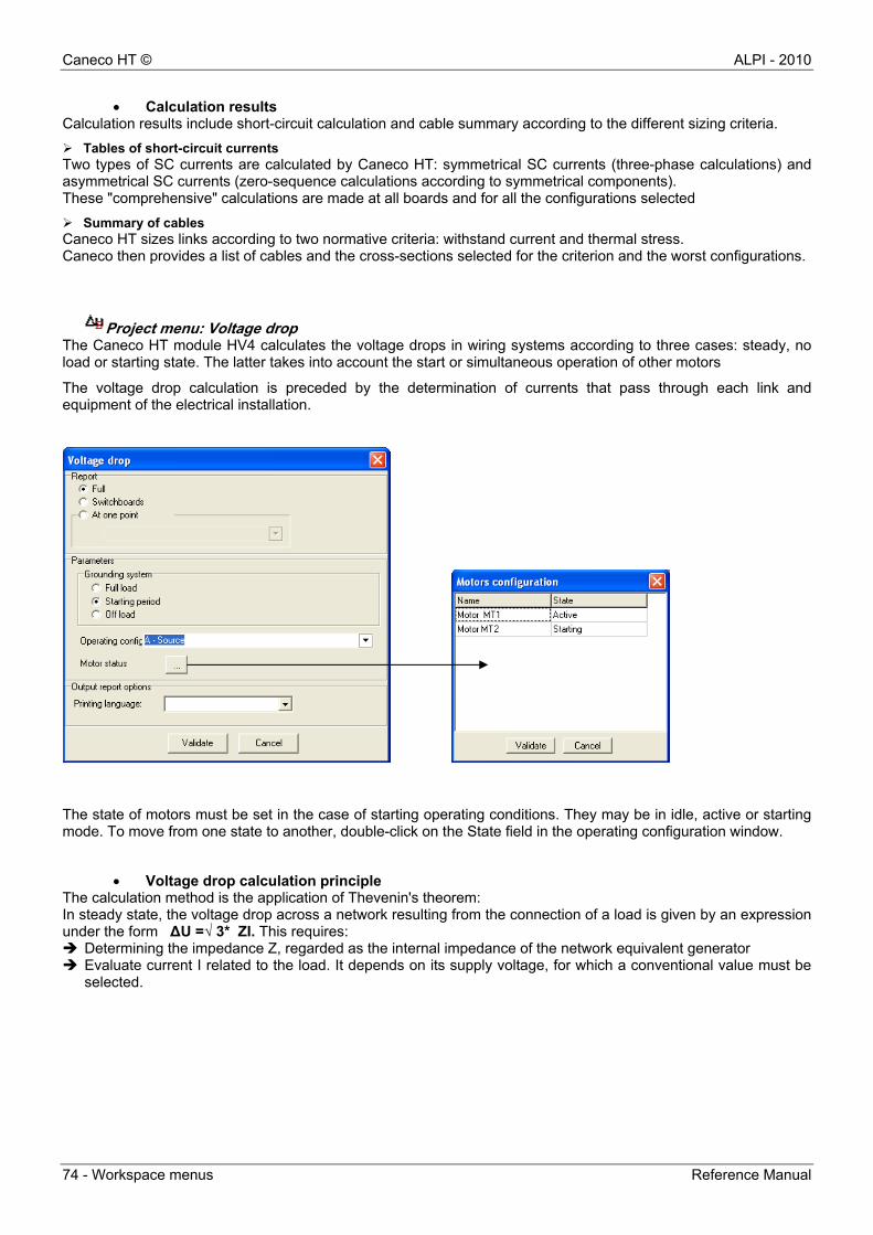
Project menu: Voltage drop The Caneco HT module HV4 calculates the voltage drops in wiring systems according to three cases: steady, no load or starting state. The latter takes into account the start or simultaneous operation of other motors
The voltage drop calculation is preceded by the determination of currents that pass through each link and equipment of the electrical installation.
The state of motors must be set in the case of starting operating conditions. They may be in idle, active or starting mode. To move from one state to another, double-click on the State field in the operating configuration window.
Voltage drop calculation principle The calculation method is the application of Thevenin's theorem: In steady state, the voltage drop across a network resulting from the connection of a load is given by an expression under the form ΔU =√ 3* ZI. This requires: Determining the impedance Z, regarded as the internal impedance of the network equivalent generator Evaluate current I related to the load. It depends on its supply voltage, for which a conventional value must be
selected.
ALPI - 2010 Caneco HT ©
Reference Manual Workspace menus - 75
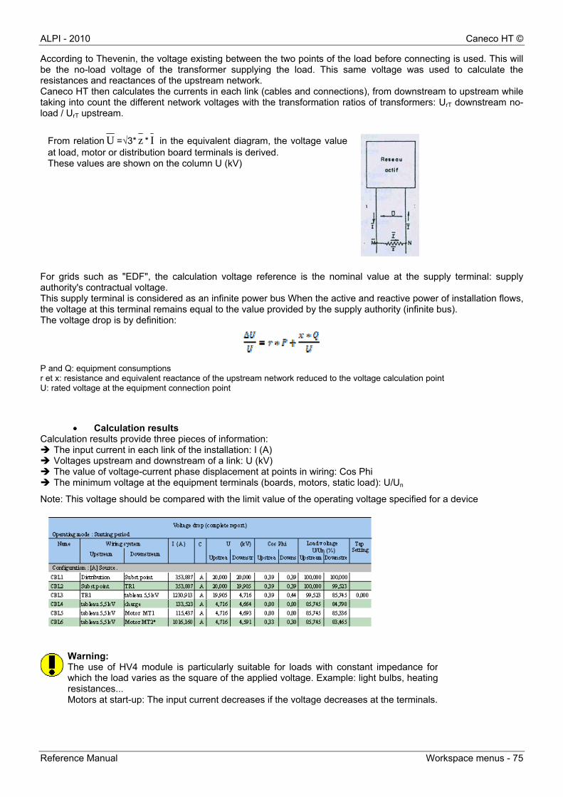
According to Thevenin, the voltage existing between the two points of the load before connecting is used. This will be the no-load voltage of the transformer supplying the load. This same voltage was used to calculate the resistances and reactances of the upstream network. Caneco HT then calculates the currents in each link (cables and connections), from downstream to upstream while taking into count the different network voltages with the transformation ratios of transformers: UrT downstream no-load / UrT upstream. For grids such as "EDF", the calculation voltage reference is the nominal value at the supply terminal: supply authority's contractual voltage. This supply terminal is considered as an infinite power bus When the active and reactive power of installation flows, the voltage at this terminal remains equal to the value provided by the supply authority (infinite bus). The voltage drop is by definition:
P and Q: equipment consumptions r et x: resistance and equivalent reactance of the upstream network reduced to the voltage calculation point U: rated voltage at the equipment connection point
Calculation results Calculation results provide three pieces of information: The input current in each link of the installation: I (A) Voltages upstream and downstream of a link: U (kV) The value of voltage-current phase displacement at points in wiring: Cos Phi The minimum voltage at the equipment terminals (boards, motors, static load): U/Un
Note: This voltage should be compared with the limit value of the operating voltage specified for a device
Warning: The use of HV4 module is particularly suitable for loads with constant impedance forwhich the load varies as the square of the applied voltage. Example: light bulbs, heatingresistances... Motors at start-up: The input current decreases if the voltage decreases at the terminals.
From relation U =√3* z * I in the equivalent diagram, the voltage value at load, motor or distribution board terminals is derived. These values are shown on the column U (kV)
Caneco HT © ALPI - 2010
76 - Workspace menus Reference Manual
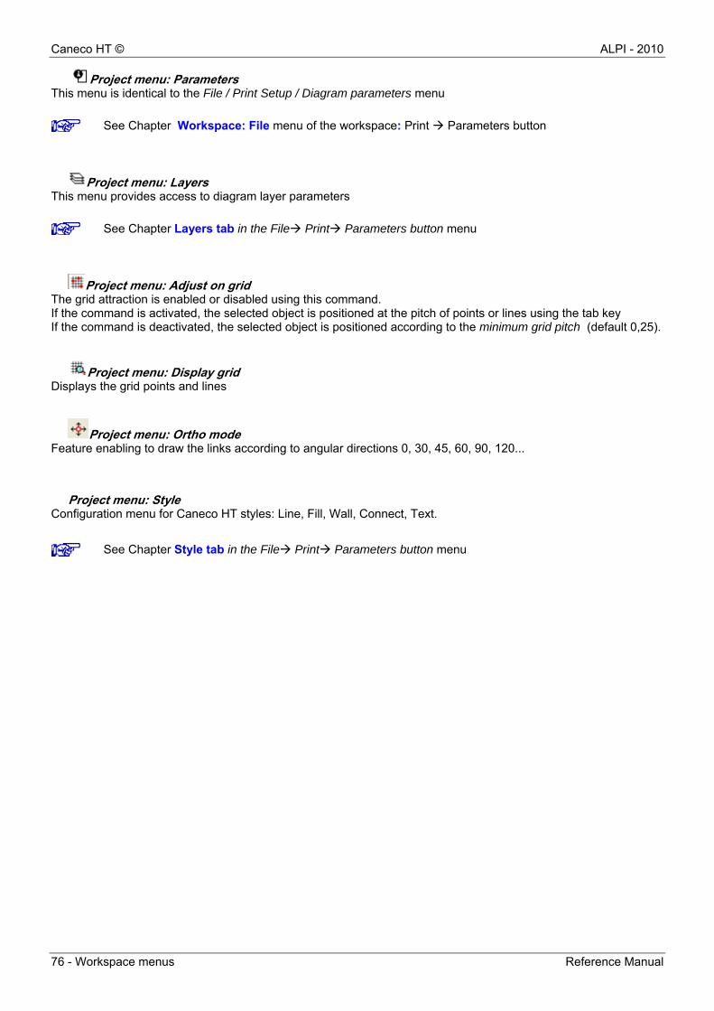
Project menu: Parameters This menu is identical to the File / Print Setup / Diagram parameters menu
Project menu: Layers This menu provides access to diagram layer parameters
Project menu: Adjust on grid The grid attraction is enabled or disabled using this command. If the command is activated, the selected object is positioned at the pitch of points or lines using the tab key If the command is deactivated, the selected object is positioned according to the minimum grid pitch (default 0,25).
Project menu: Display grid Displays the grid points and lines
Project menu: Ortho mode Feature enabling to draw the links according to angular directions 0, 30, 45, 60, 90, 120...
Project menu: Style Configuration menu for Caneco HT styles: Line, Fill, Wall, Connect, Text.
See Chapter Workspace: File menu of the workspace: Print Parameters button
See Chapter Layers tab in the File Print Parameters button menu
See Chapter Style tab in the File Print Parameters button menu
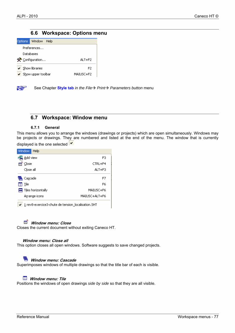
ALPI - 2010 Caneco HT ©
Reference Manual Workspace menus - 77
6.6 Workspace: Options menu
6.7 Workspace: Window menu
6.7.1 General
This menu allows you to arrange the windows (drawings or projects) which are open simultaneously. Windows may be projects or drawings. They are numbered and listed at the end of the menu. The window that is currently
displayed is the one selected
Window menu: Close Closes the current document without exiting Caneco HT.
Window menu: Close all This option closes all open windows. Software suggests to save changed projects.
Window menu: Cascade Superimposes windows of multiple drawings so that the title bar of each is visible.
Window menu: Tile Positions the windows of open drawings side by side so that they are all visible.
See Chapter Style tab in the File Print Parameters button menu
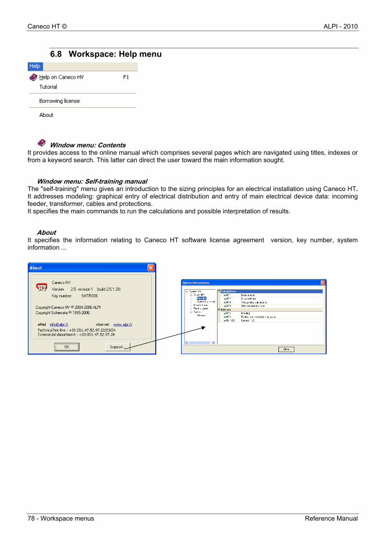
Caneco HT © ALPI - 2010
78 - Workspace menus Reference Manual
6.8 Workspace: Help menu
Window menu: Contents It provides access to the online manual which comprises several pages which are navigated using titles, indexes or from a keyword search. This latter can direct the user toward the main information sought.
Window menu: Self-training manual The "self-training" menu gives an introduction to the sizing principles for an electrical installation using Caneco HT. It addresses modeling: graphical entry of electrical distribution and entry of main electrical device data: incoming feeder, transformer, cables and protections. It specifies the main commands to run the calculations and possible interpretation of results.
About It specifies the information relating to Caneco HT software license agreement version, key number, system information ...
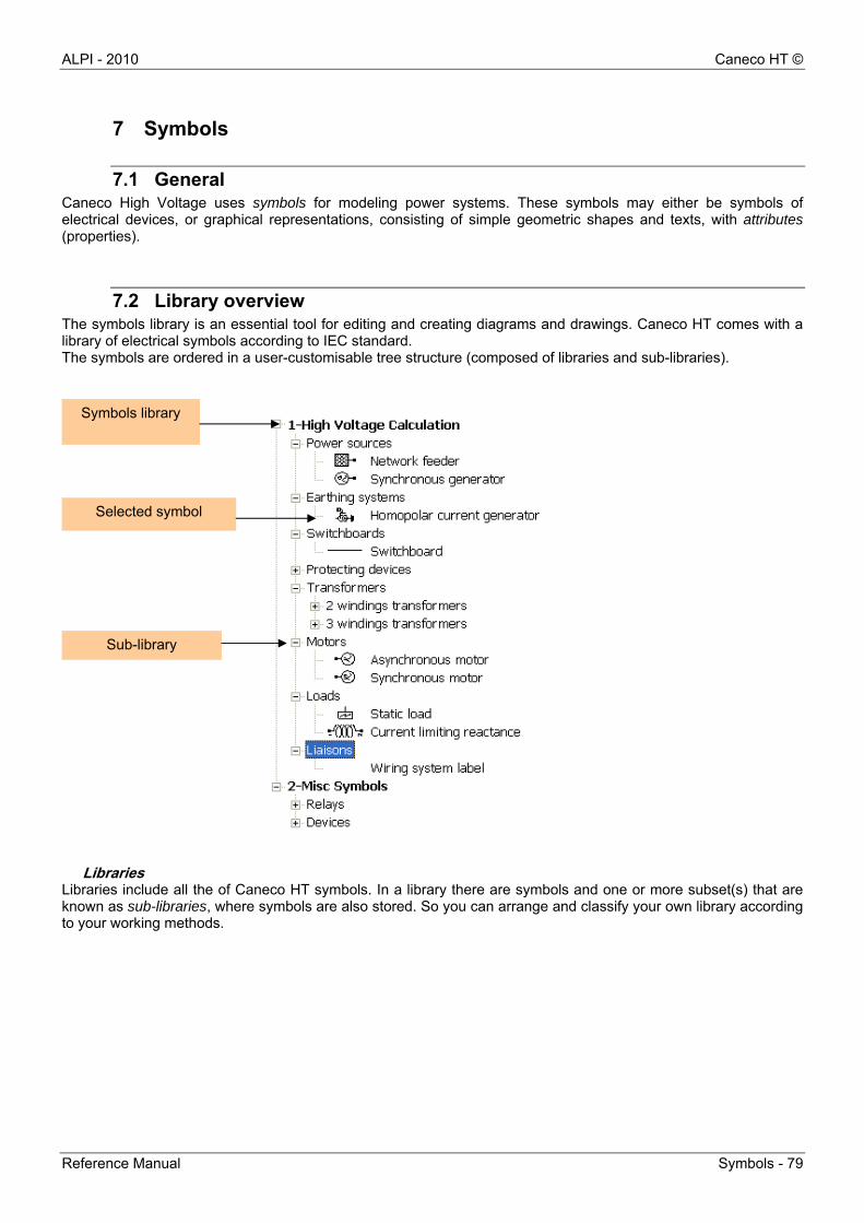
ALPI - 2010 Caneco HT ©
Reference Manual Symbols - 79
7 Symbols
7.1 General Caneco High Voltage uses symbols for modeling power systems. These symbols may either be symbols of electrical devices, or graphical representations, consisting of simple geometric shapes and texts, with attributes (properties).
7.2 Library overview The symbols library is an essential tool for editing and creating diagrams and drawings. Caneco HT comes with a library of electrical symbols according to IEC standard. The symbols are ordered in a user-customisable tree structure (composed of libraries and sub-libraries).
Libraries Libraries include all the of Caneco HT symbols. In a library there are symbols and one or more subset(s) that are known as sub-libraries, where symbols are also stored. So you can arrange and classify your own library according to your working methods.
Symbols library
Selected symbol
Sub-library
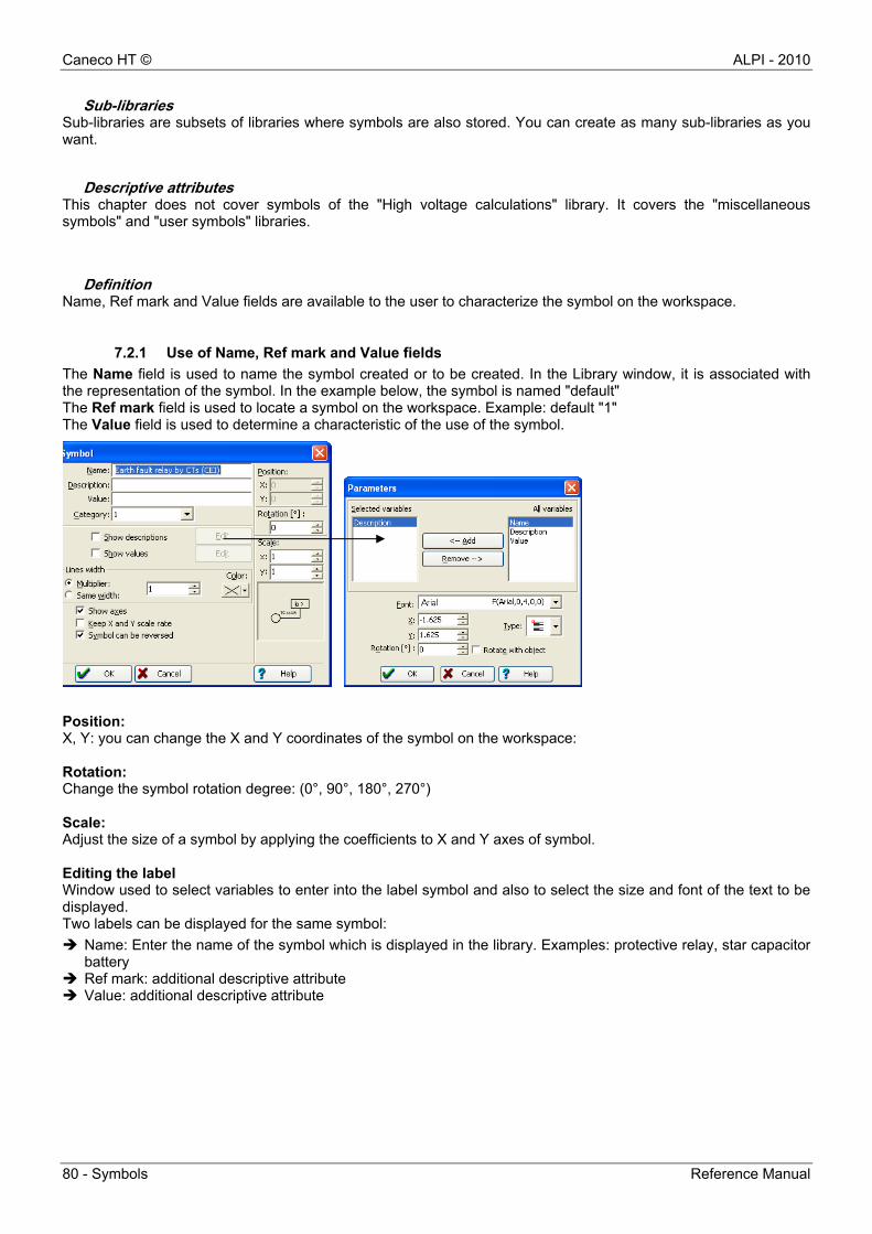
Caneco HT © ALPI - 2010
80 - Symbols Reference Manual
Sub-libraries Sub-libraries are subsets of libraries where symbols are also stored. You can create as many sub-libraries as you want.
Descriptive attributes This chapter does not cover symbols of the "High voltage calculations" library. It covers the "miscellaneous symbols" and "user symbols" libraries.
Definition Name, Ref mark and Value fields are available to the user to characterize the symbol on the workspace.
7.2.1 Use of Name, Ref mark and Value fields
The Name field is used to name the symbol created or to be created. In the Library window, it is associated with the representation of the symbol. In the example below, the symbol is named "default" The Ref mark field is used to locate a symbol on the workspace. Example: default "1" The Value field is used to determine a characteristic of the use of the symbol.
Position: X, Y: you can change the X and Y coordinates of the symbol on the workspace: Rotation: Change the symbol rotation degree: (0°, 90°, 180°, 270°) Scale: Adjust the size of a symbol by applying the coefficients to X and Y axes of symbol. Editing the label Window used to select variables to enter into the label symbol and also to select the size and font of the text to be displayed. Two labels can be displayed for the same symbol:
Name: Enter the name of the symbol which is displayed in the library. Examples: protective relay, star capacitor battery
Ref mark: additional descriptive attribute Value: additional descriptive attribute
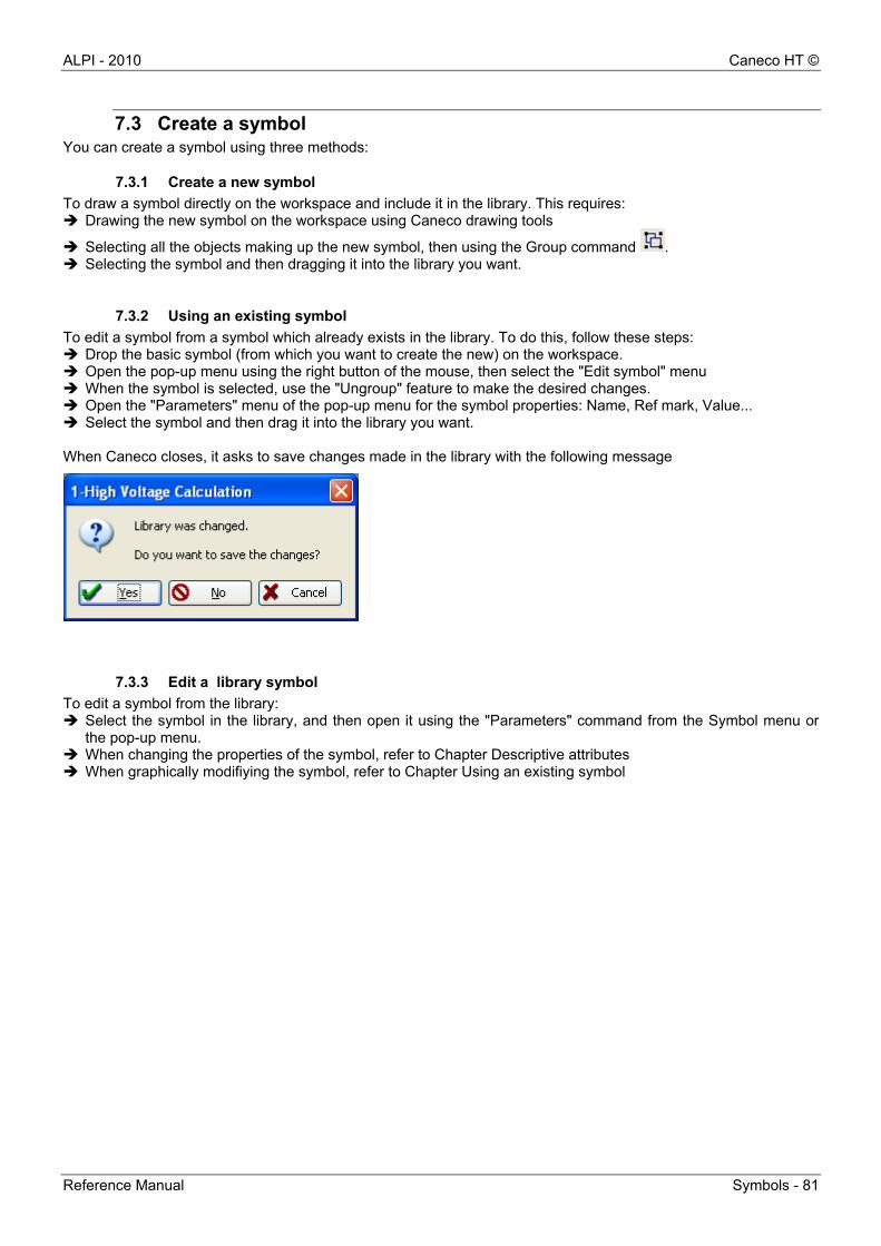
ALPI - 2010 Caneco HT ©
Reference Manual Symbols - 81
7.3 Create a symbol You can create a symbol using three methods:
7.3.1 Create a new symbol
To draw a symbol directly on the workspace and include it in the library. This requires: Drawing the new symbol on the workspace using Caneco drawing tools
Selecting all the objects making up the new symbol, then using the Group command . Selecting the symbol and then dragging it into the library you want.
7.3.2 Using an existing symbol
To edit a symbol from a symbol which already exists in the library. To do this, follow these steps: Drop the basic symbol (from which you want to create the new) on the workspace. Open the pop-up menu using the right button of the mouse, then select the "Edit symbol" menu When the symbol is selected, use the "Ungroup" feature to make the desired changes. Open the "Parameters" menu of the pop-up menu for the symbol properties: Name, Ref mark, Value... Select the symbol and then drag it into the library you want. When Caneco closes, it asks to save changes made in the library with the following message
7.3.3 Edit a library symbol
To edit a symbol from the library: Select the symbol in the library, and then open it using the "Parameters" command from the Symbol menu or
the pop-up menu. When changing the properties of the symbol, refer to Chapter Descriptive attributes When graphically modifiying the symbol, refer to Chapter Using an existing symbol

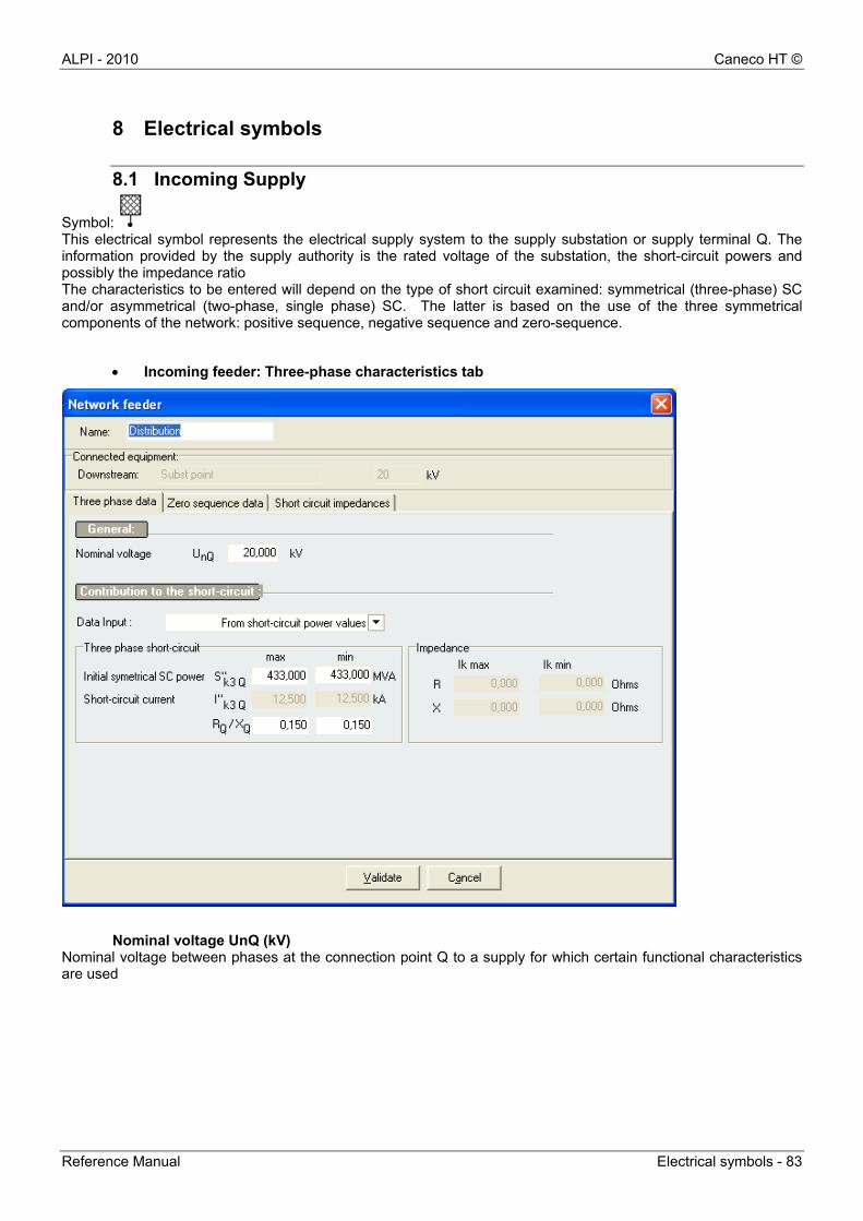
ALPI - 2010 Caneco HT ©
Reference Manual Electrical symbols - 83
8 Electrical symbols
8.1 Incoming Supply
Symbol: This electrical symbol represents the electrical supply system to the supply substation or supply terminal Q. The information provided by the supply authority is the rated voltage of the substation, the short-circuit powers and possibly the impedance ratio The characteristics to be entered will depend on the type of short circuit examined: symmetrical (three-phase) SC and/or asymmetrical (two-phase, single phase) SC. The latter is based on the use of the three symmetrical components of the network: positive sequence, negative sequence and zero-sequence.
Incoming feeder: Three-phase characteristics tab
Nominal voltage UnQ (kV)
Nominal voltage between phases at the connection point Q to a supply for which certain functional characteristics are used
Caneco HT © ALPI - 2010
84 - Electrical symbols Reference Manual
Data entry Specifications provided by the supply authority that can be specified as short-circuit power, short-circuit current, or short-circuit impedances
Short-circuit power S’’k3Q (MVA)
Notional value defined as the product of the initial symmetrical short-circuit current I''k3, the nominal voltage UnQ at the connection point Q and the factor √3: S’’k3Q=√3 * UnQ* I’’k3 Two short-circuit powers are entered: Short-circuit power S’’k3Qmax It corresponds to the maximum current input from the three-phase short-circuit current of the public distribution network Min short-circuit power S’’k3Qmin It corresponds to the minimum current input from the three-phase short-circuit current of the public distribution network
Short-circuit current I’’k3Q (kA) Rms value of the AC symmetrical component of an initial three-phase short-circuit current at connection point Q. Max short-circuit current I’’k3Qmax It corresponds to the maximum current input from the three-phase short-circuit current of the public distribution network Min short-circuit current I’’k3Qmin It corresponds to the minimum current input from the three-phase short-circuit current of the public distribution network
RQ/XQ Impedance ratio of the supply system at the connection point Q. Knowing the impedance ZQ calculated from the short-circuit power or current, this ratio will determine the network R and X components at the connection point: Impedance ratio RQ/XQmax This ratio calculates the reactance XQmax used for the calculation of maximum short-circuit currents. Impedance ratio RQ/XQmin This ratio calculates the reactance XQmin used for the calculation of minimum short-circuit currents
If the min characteristics are not specified, Caneco HT considers that: S’’k3Qmax =S’’k3Qmin and RQ/XQmax= RQ/XQmin
Short-circuit impedance (ohms) Short-circuit impedance of supply system at the connection point Q. It is calculated from the short-circuit power or current of the upstream network:
Equivalent reactance XQ of upstream network
Equivalent resistance R Q of upstream network
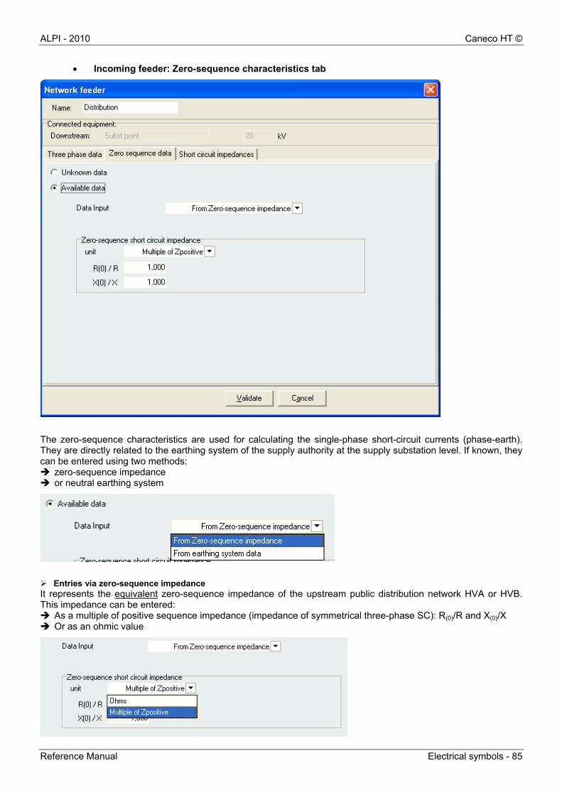
ALPI - 2010 Caneco HT ©
Reference Manual Electrical symbols - 85
Incoming feeder: Zero-sequence characteristics tab
The zero-sequence characteristics are used for calculating the single-phase short-circuit currents (phase-earth). They are directly related to the earthing system of the supply authority at the supply substation level. If known, they can be entered using two methods: zero-sequence impedance or neutral earthing system
Entries via zero-sequence impedance It represents the equivalent zero-sequence impedance of the upstream public distribution network HVA or HVB. This impedance can be entered: As a multiple of positive sequence impedance (impedance of symmetrical three-phase SC): R(0)/R and X(0)/X Or as an ohmic value
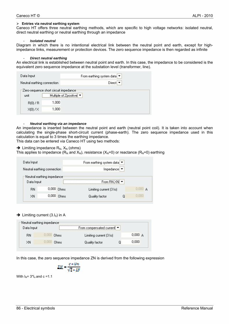
Caneco HT © ALPI - 2010
86 - Electrical symbols Reference Manual
Entries via neutral earthing system Caneco HT offers three neutral earthing methods, which are specific to high voltage networks: isolated neutral, direct neutral earthing or neutral earthing through an impedance
- Isolated neutral Diagram in which there is no intentional electrical link between the neutral point and earth, except for high-impedance links, measurement or protection devices. The zero sequence impedance is then regarded as infinite
- Direct neutral earthing An electrical link is established between neutral point and earth. In this case, the impedance to be considered is the equivalent zero sequence impedance at the substation level (transformer, line).
- Neutral earthing via an impedance
An impedance is inserted between the neutral point and earth (neutral point coil). It is taken into account when calculating the single-phase short-circuit current (phase-earth). The zero sequence impedance used in this calculation is equal to 3 times the earthing impedance. This data can be entered via Caneco HT using two methods:
Limiting impedance RN, XN (ohms) This applies to impedance (RN and XN), resistance (XN=0) or reactance (RN=0) earthing
Limiting current (3.I0) in A
In this case, the zero sequence impedance ZN is derived from the following expression
With IN= 3*Io and c =1.1
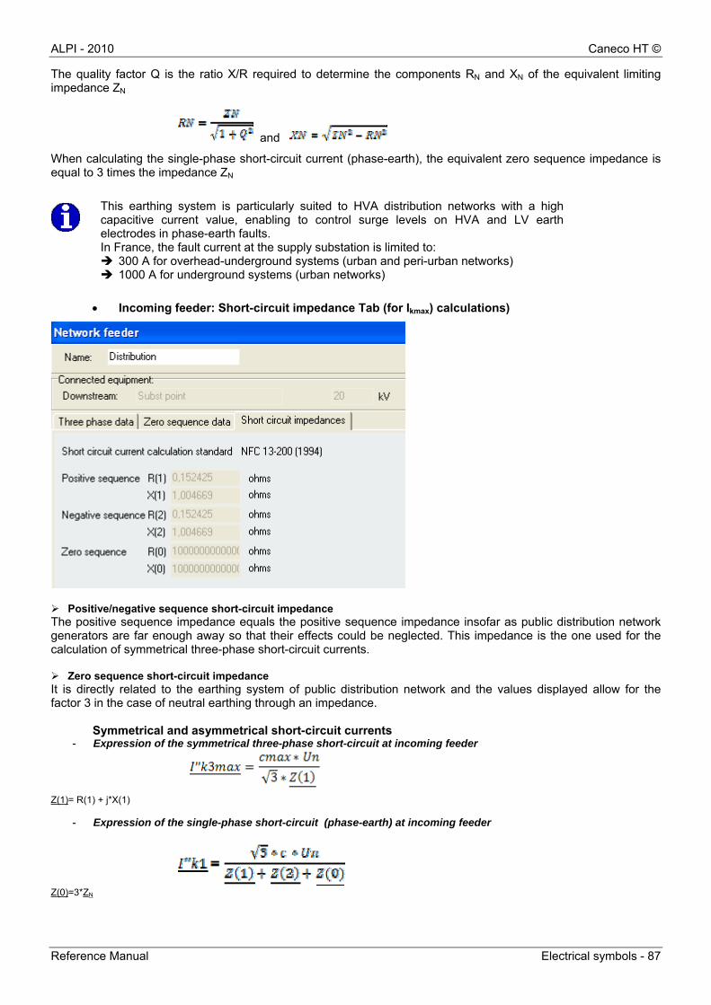
ALPI - 2010 Caneco HT ©
Reference Manual Electrical symbols - 87
The quality factor Q is the ratio X/R required to determine the components RN and XN of the equivalent limiting impedance ZN
and
When calculating the single-phase short-circuit current (phase-earth), the equivalent zero sequence impedance is equal to 3 times the impedance ZN
Incoming feeder: Short-circuit impedance Tab (for Ikmax) calculations)
Positive/negative sequence short-circuit impedance The positive sequence impedance equals the positive sequence impedance insofar as public distribution network generators are far enough away so that their effects could be neglected. This impedance is the one used for the calculation of symmetrical three-phase short-circuit currents. Zero sequence short-circuit impedance It is directly related to the earthing system of public distribution network and the values displayed allow for the factor 3 in the case of neutral earthing through an impedance.
Symmetrical and asymmetrical short-circuit currents - Expression of the symmetrical three-phase short-circuit at incoming feeder
Z(1)= R(1) + j*X(1)
- Expression of the single-phase short-circuit (phase-earth) at incoming feeder
Z(0)=3*ZN
This earthing system is particularly suited to HVA distribution networks with a highcapacitive current value, enabling to control surge levels on HVA and LV earthelectrodes in phase-earth faults. In France, the fault current at the supply substation is limited to: 300 A for overhead-underground systems (urban and peri-urban networks) 1000 A for underground systems (urban networks)
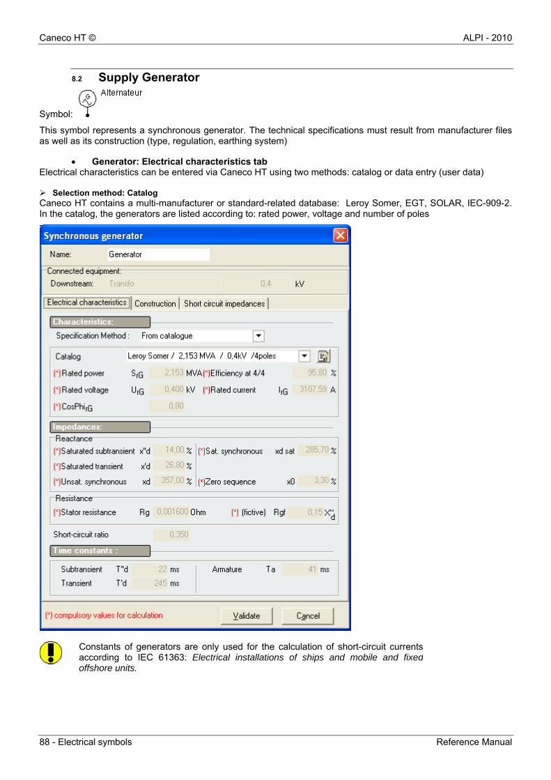
Caneco HT © ALPI - 2010
88 - Electrical symbols Reference Manual
8.2 Supply Generator
Symbol:
This symbol represents a synchronous generator. The technical specifications must result from manufacturer files as well as its construction (type, regulation, earthing system)
Generator: Electrical characteristics tab Electrical characteristics can be entered via Caneco HT using two methods: catalog or data entry (user data) Selection method: Catalog Caneco HT contains a multi-manufacturer or standard-related database: Leroy Somer, EGT, SOLAR, IEC-909-2. In the catalog, the generators are listed according to: rated power, voltage and number of poles
Constants of generators are only used for the calculation of short-circuit currentsaccording to IEC 61363: Electrical installations of ships and mobile and fixedoffshore units.
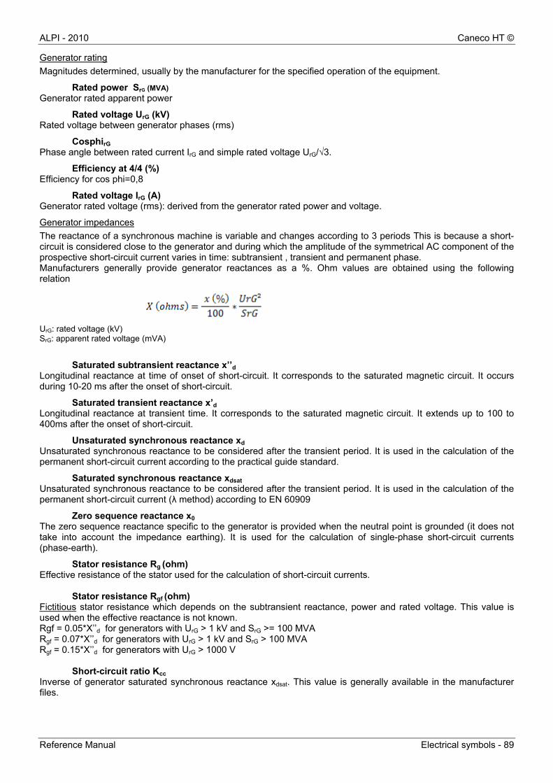
ALPI - 2010 Caneco HT ©
Reference Manual Electrical symbols - 89
Generator rating
Magnitudes determined, usually by the manufacturer for the specified operation of the equipment.
Rated power SrG (MVA)
Generator rated apparent power
Rated voltage UrG (kV) Rated voltage between generator phases (rms)
CosphirG Phase angle between rated current IrG and simple rated voltage UrG/√3.
Efficiency at 4/4 (%) Efficiency for cos phi=0,8
Rated voltage IrG (A) Generator rated voltage (rms): derived from the generator rated power and voltage.
Generator impedances
The reactance of a synchronous machine is variable and changes according to 3 periods This is because a short-circuit is considered close to the generator and during which the amplitude of the symmetrical AC component of the prospective short-circuit current varies in time: subtransient , transient and permanent phase. Manufacturers generally provide generator reactances as a %. Ohm values are obtained using the following relation
UrG: rated voltage (kV) SrG: apparent rated voltage (mVA)
Saturated subtransient reactance x’’d Longitudinal reactance at time of onset of short-circuit. It corresponds to the saturated magnetic circuit. It occurs during 10-20 ms after the onset of short-circuit.
Saturated transient reactance x’d Longitudinal reactance at transient time. It corresponds to the saturated magnetic circuit. It extends up to 100 to 400ms after the onset of short-circuit.
Unsaturated synchronous reactance xd Unsaturated synchronous reactance to be considered after the transient period. It is used in the calculation of the permanent short-circuit current according to the practical guide standard.
Saturated synchronous reactance xdsat Unsaturated synchronous reactance to be considered after the transient period. It is used in the calculation of the permanent short-circuit current (λ method) according to EN 60909
Zero sequence reactance x0 The zero sequence reactance specific to the generator is provided when the neutral point is grounded (it does not take into account the impedance earthing). It is used for the calculation of single-phase short-circuit currents (phase-earth).
Stator resistance Rg (ohm) Effective resistance of the stator used for the calculation of short-circuit currents.
Stator resistance Rgf (ohm) Fictitious stator resistance which depends on the subtransient reactance, power and rated voltage. This value is used when the effective reactance is not known. Rgf = 0.05*X’’d for generators with UrG > 1 kV and SrG >= 100 MVA Rgf = 0.07*X’’d for generators with UrG > 1 kV and SrG > 100 MVA Rgf = 0.15*X’’d for generators with UrG > 1000 V
Short-circuit ratio Kcc Inverse of generator saturated synchronous reactance xdsat. This value is generally available in the manufacturer files.
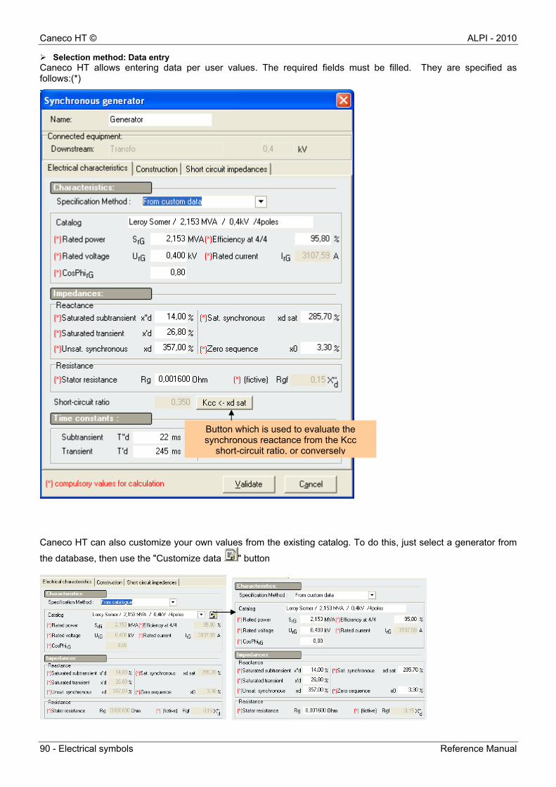
Caneco HT © ALPI - 2010
90 - Electrical symbols Reference Manual
Selection method: Data entry Caneco HT allows entering data per user values. The required fields must be filled. They are specified as follows:(*)
Caneco HT can also customize your own values from the existing catalog. To do this, just select a generator from
the database, then use the "Customize data " button
Button which is used to evaluate the synchronous reactance from the Kcc
short-circuit ratio, or conversely
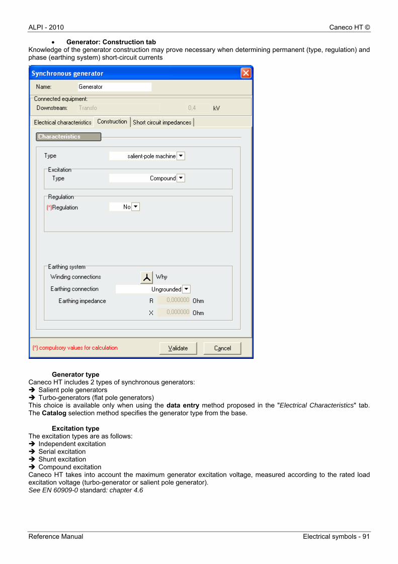
ALPI - 2010 Caneco HT ©
Reference Manual Electrical symbols - 91
Generator: Construction tab Knowledge of the generator construction may prove necessary when determining permanent (type, regulation) and phase (earthing system) short-circuit currents
Generator type
Caneco HT includes 2 types of synchronous generators: Salient pole generators Turbo-generators (flat pole generators) This choice is available only when using the data entry method proposed in the "Electrical Characteristics" tab. The Catalog selection method specifies the generator type from the base.
Excitation type The excitation types are as follows: Independent excitation Serial excitation Shunt excitation Compound excitation Caneco HT takes into account the maximum generator excitation voltage, measured according to the rated load excitation voltage (turbo-generator or salient pole generator). See EN 60909-0 standard: chapter 4.6
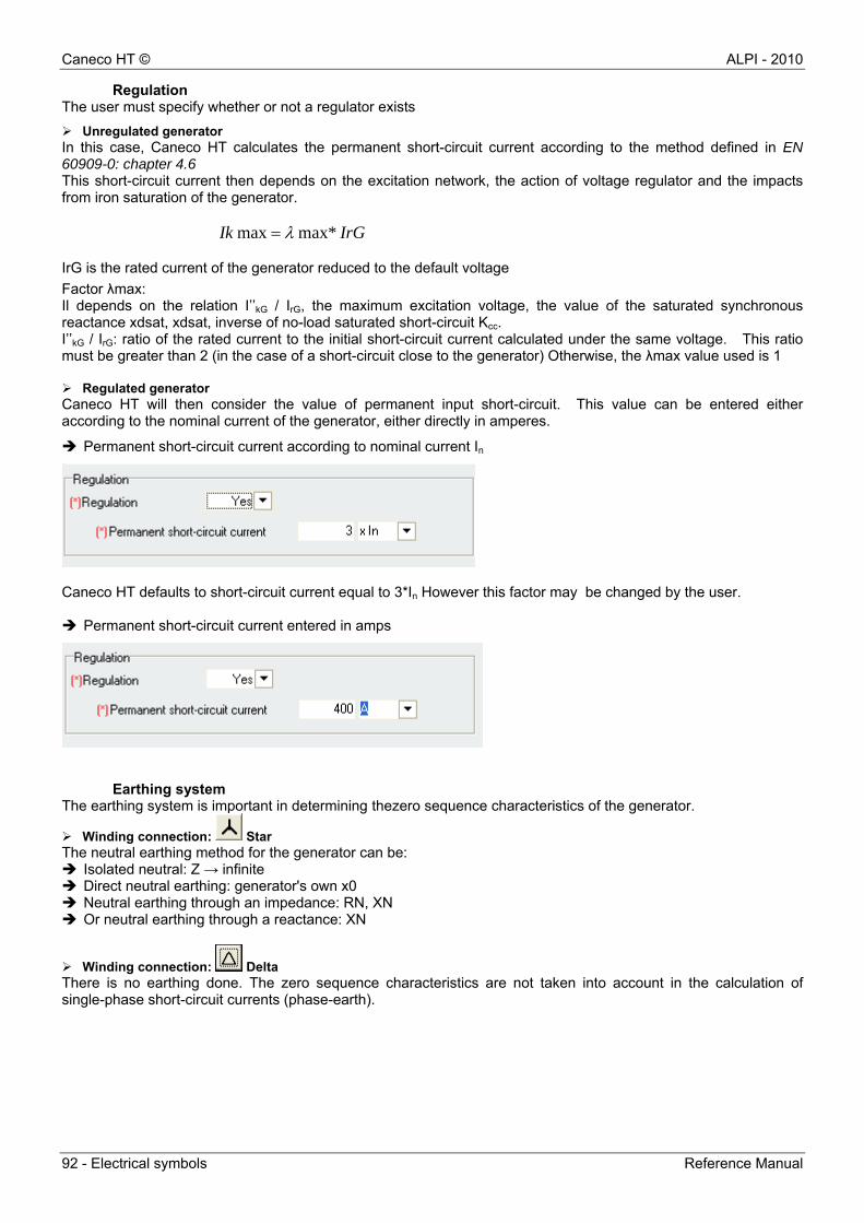
Caneco HT © ALPI - 2010
92 - Electrical symbols Reference Manual
Regulation The user must specify whether or not a regulator exists
Unregulated generator In this case, Caneco HT calculates the permanent short-circuit current according to the method defined in EN 60909-0: chapter 4.6 This short-circuit current then depends on the excitation network, the action of voltage regulator and the impacts from iron saturation of the generator.
IrGIk max*max IrG is the rated current of the generator reduced to the default voltage
Factor λmax: Il depends on the relation I’’kG / IrG, the maximum excitation voltage, the value of the saturated synchronous reactance xdsat, xdsat, inverse of no-load saturated short-circuit Kcc. I’’kG / IrG: ratio of the rated current to the initial short-circuit current calculated under the same voltage. This ratio must be greater than 2 (in the case of a short-circuit close to the generator) Otherwise, the λmax value used is 1 Regulated generator Caneco HT will then consider the value of permanent input short-circuit. This value can be entered either according to the nominal current of the generator, either directly in amperes.
Permanent short-circuit current according to nominal current In
Caneco HT defaults to short-circuit current equal to 3*In However this factor may be changed by the user. Permanent short-circuit current entered in amps
Earthing system The earthing system is important in determining thezero sequence characteristics of the generator.
Winding connection: Star The neutral earthing method for the generator can be: Isolated neutral: Z → infinite Direct neutral earthing: generator's own x0 Neutral earthing through an impedance: RN, XN Or neutral earthing through a reactance: XN
Winding connection: Delta There is no earthing done. The zero sequence characteristics are not taken into account in the calculation of single-phase short-circuit currents (phase-earth).
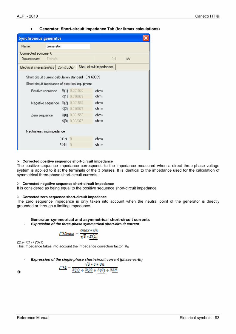
ALPI - 2010 Caneco HT ©
Reference Manual Electrical symbols - 93
Generator: Short-circuit impedance Tab (for Ikmax calculations)
Corrected positive sequence short-circuit impedance The positive sequence impedance corresponds to the impedance measured when a direct three-phase voltage system is applied to it at the terminals of the 3 phases. It is identical to the impedance used for the calculation of symmetrical three-phase short-circuit currents. Corrected negative sequence short-circuit impedance It is considered as being equal to the positive sequence short-circuit impedance. Corrected zero sequence short-circuit impedance The zero sequence impedance is only taken into account when the neutral point of the generator is directly grounded or through a limiting impedance.
Generator symmetrical and asymmetrical short-circuit currents - Expression of the three-phase symmetrical short-circuit current
Z(1)= R(1) + j*X(1) This impedance takes into account the impedance correction factor KG
- Expression of the single-phase short-circuit current (phase-earth)

Caneco HT © ALPI - 2010
94 - Electrical symbols Reference Manual
8.3 Earthing by zero sequence generator
Symbol: The zero sequence generator or artificial neutral is used when the neutral is not accessible (delta winding ) or when there are several independent supplies that can operate in parallel.
The ratio R0/X0 is required to determine the components R0 et X0 of the equivalent limiting impedance Limiting impedance calculation
Limiting resistance calculation
Limiting reactance calculation
8.4 Board Symbol: The board device represents an allocation or distribution busbar. Other electrical devices are connected to the board via links The board voltage must be in the order of magnitude of the link voltage(+/- 8%)
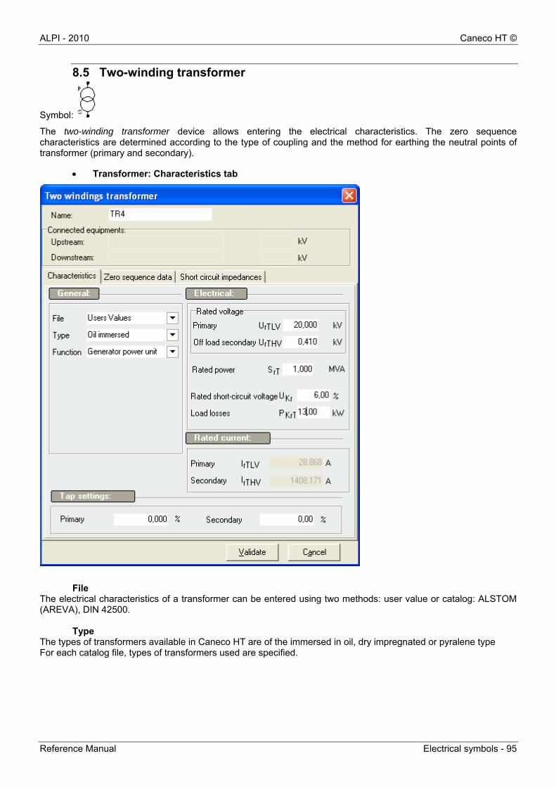
ALPI - 2010 Caneco HT ©
Reference Manual Electrical symbols - 95
8.5 Two-winding transformer
Symbol:
The two-winding transformer device allows entering the electrical characteristics. The zero sequence characteristics are determined according to the type of coupling and the method for earthing the neutral points of transformer (primary and secondary).
Transformer: Characteristics tab
File
The electrical characteristics of a transformer can be entered using two methods: user value or catalog: ALSTOM (AREVA), DIN 42500.
Type The types of transformers available in Caneco HT are of the immersed in oil, dry impregnated or pyralene type For each catalog file, types of transformers used are specified.
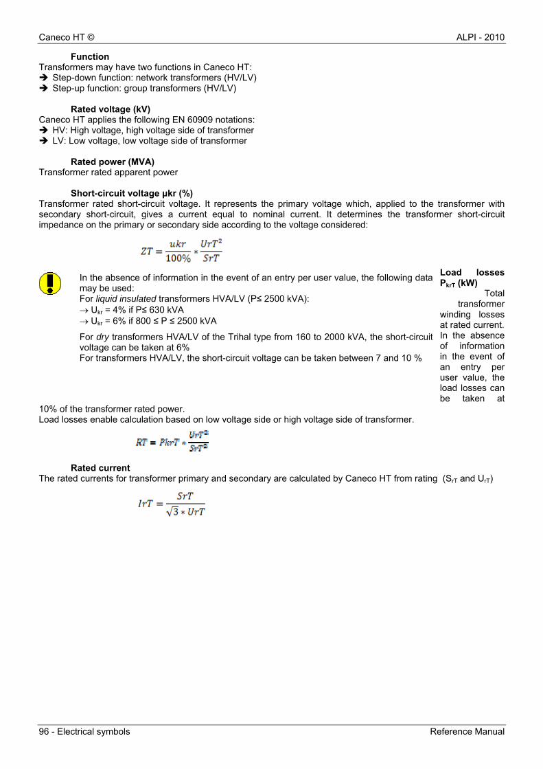
Caneco HT © ALPI - 2010
96 - Electrical symbols Reference Manual
Function Transformers may have two functions in Caneco HT: Step-down function: network transformers (HV/LV) Step-up function: group transformers (HV/LV)
Rated voltage (kV)
Caneco HT applies the following EN 60909 notations: HV: High voltage, high voltage side of transformer LV: Low voltage, low voltage side of transformer
Rated power (MVA) Transformer rated apparent power
Short-circuit voltage μkr (%) Transformer rated short-circuit voltage. It represents the primary voltage which, applied to the transformer with secondary short-circuit, gives a current equal to nominal current. It determines the transformer short-circuit impedance on the primary or secondary side according to the voltage considered:
Load losses PkrT (kW)
Total transformer
winding losses at rated current. In the absence of information in the event of an entry per user value, the load losses can be taken at
10% of the transformer rated power. Load losses enable calculation based on low voltage side or high voltage side of transformer.
Rated current The rated currents for transformer primary and secondary are calculated by Caneco HT from rating (SrT and UrT)
In the absence of information in the event of an entry per user value, the following datamay be used: For liquid insulated transformers HVA/LV (P≤ 2500 kVA): Ukr = 4% if P≤ 630 kVA Ukr = 6% if 800 ≤ P ≤ 2500 kVA
For dry transformers HVA/LV of the Trihal type from 160 to 2000 kVA, the short-circuit voltage can be taken at 6% For transformers HVA/LV, the short-circuit voltage can be taken between 7 and 10 %
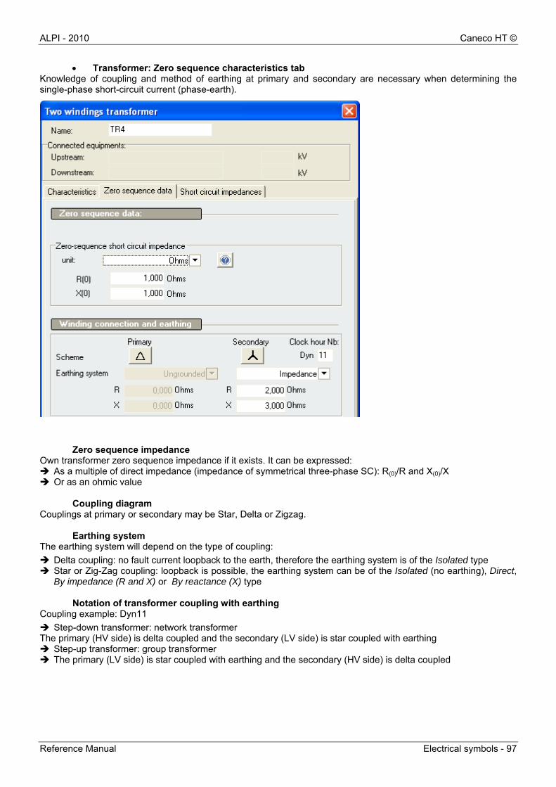
ALPI - 2010 Caneco HT ©
Reference Manual Electrical symbols - 97
Transformer: Zero sequence characteristics tab Knowledge of coupling and method of earthing at primary and secondary are necessary when determining the single-phase short-circuit current (phase-earth).
Zero sequence impedance Own transformer zero sequence impedance if it exists. It can be expressed: As a multiple of direct impedance (impedance of symmetrical three-phase SC): R(0)/R and X(0)/X Or as an ohmic value
Coupling diagram Couplings at primary or secondary may be Star, Delta or Zigzag.
Earthing system
The earthing system will depend on the type of coupling:
Delta coupling: no fault current loopback to the earth, therefore the earthing system is of the Isolated type Star or Zig-Zag coupling: loopback is possible, the earthing system can be of the Isolated (no earthing), Direct,
By impedance (R and X) or By reactance (X) type
Notation of transformer coupling with earthing Coupling example: Dyn11
Step-down transformer: network transformer The primary (HV side) is delta coupled and the secondary (LV side) is star coupled with earthing Step-up transformer: group transformer The primary (LV side) is star coupled with earthing and the secondary (HV side) is delta coupled
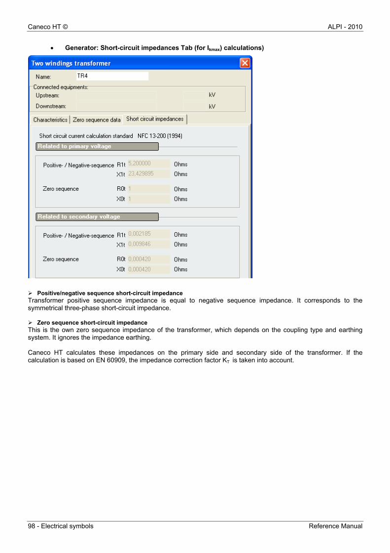
Caneco HT © ALPI - 2010
98 - Electrical symbols Reference Manual
Generator: Short-circuit impedances Tab (for Ikmax) calculations)
Positive/negative sequence short-circuit impedance Transformer positive sequence impedance is equal to negative sequence impedance. It corresponds to the symmetrical three-phase short-circuit impedance. Zero sequence short-circuit impedance This is the own zero sequence impedance of the transformer, which depends on the coupling type and earthing system. It ignores the impedance earthing. Caneco HT calculates these impedances on the primary side and secondary side of the transformer. If the calculation is based on EN 60909, the impedance correction factor KT is taken into account.
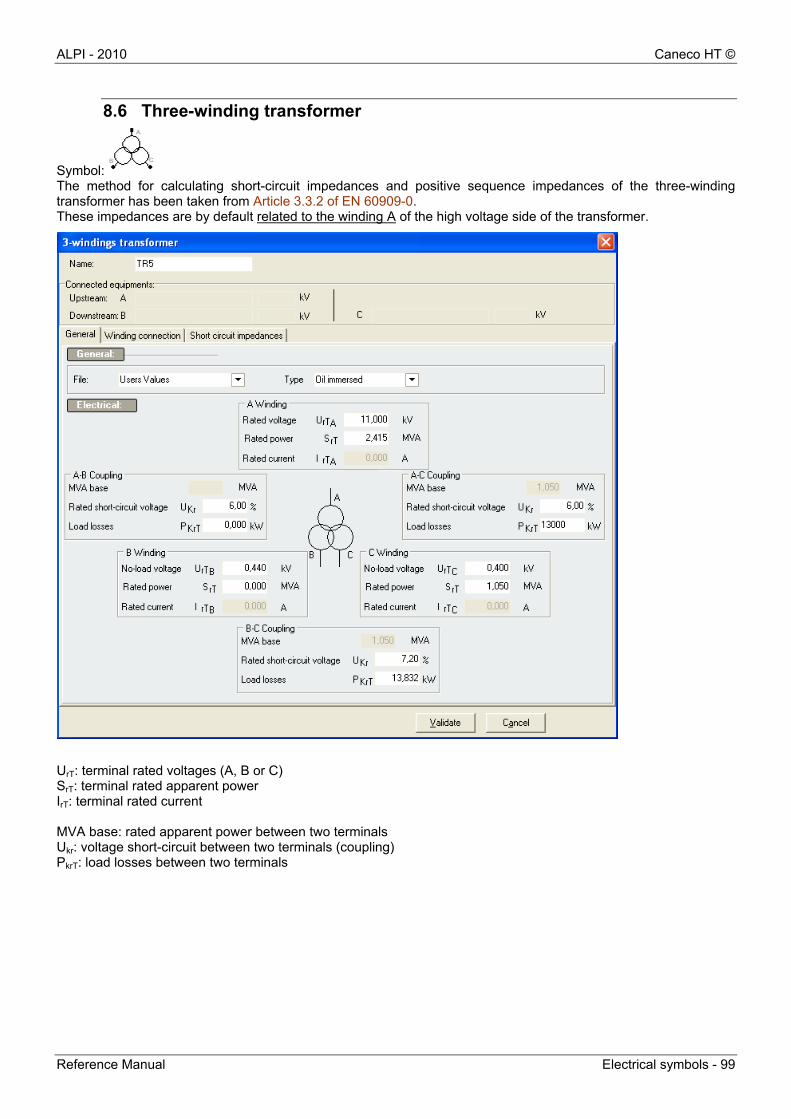
ALPI - 2010 Caneco HT ©
Reference Manual Electrical symbols - 99
8.6 Three-winding transformer
Symbol: The method for calculating short-circuit impedances and positive sequence impedances of the three-winding transformer has been taken from Article 3.3.2 of EN 60909-0. These impedances are by default related to the winding A of the high voltage side of the transformer.
UrT: terminal rated voltages (A, B or C) SrT: terminal rated apparent power IrT: terminal rated current MVA base: rated apparent power between two terminals Ukr: voltage short-circuit between two terminals (coupling) PkrT: load losses between two terminals
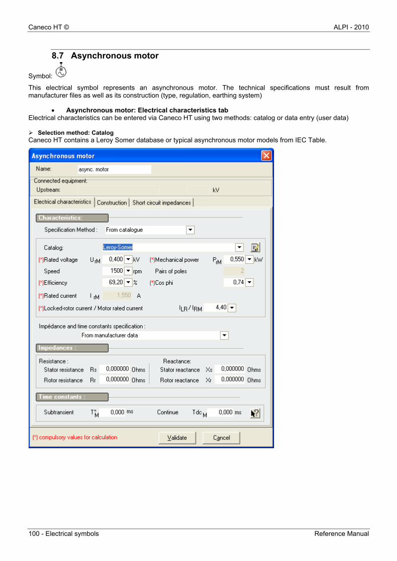
Caneco HT © ALPI - 2010
100 - Electrical symbols Reference Manual
8.7 Asynchronous motor
Symbol:
This electrical symbol represents an asynchronous motor. The technical specifications must result from manufacturer files as well as its construction (type, regulation, earthing system)
Asynchronous motor: Electrical characteristics tab Electrical characteristics can be entered via Caneco HT using two methods: catalog or data entry (user data) Selection method: Catalog Caneco HT contains a Leroy Somer database or typical asynchronous motor models from IEC Table.
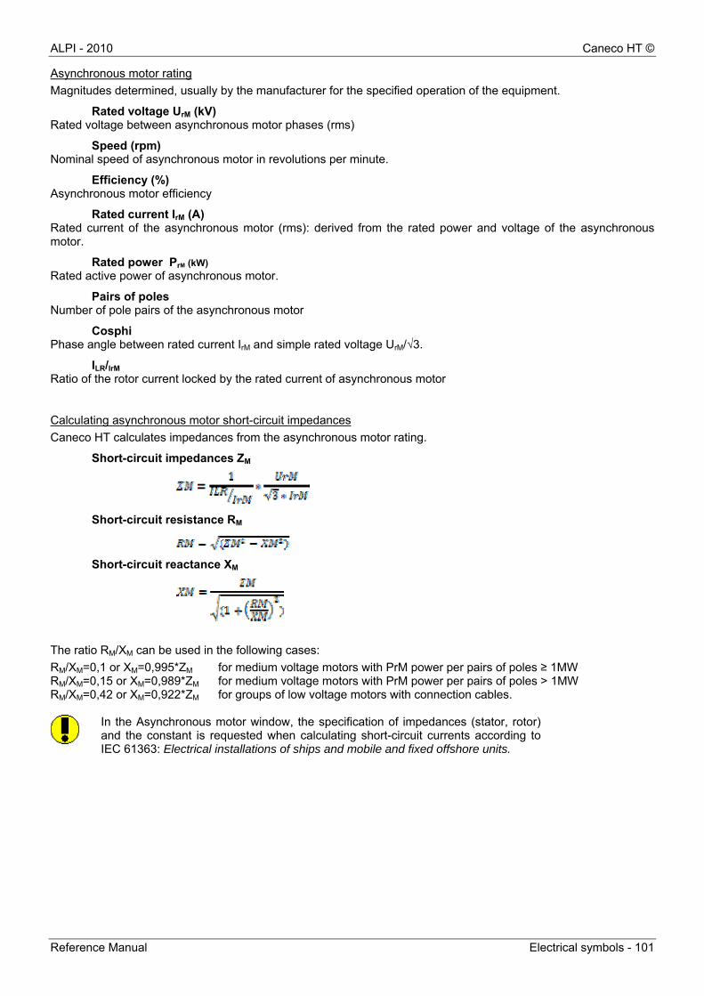
ALPI - 2010 Caneco HT ©
Reference Manual Electrical symbols - 101
Asynchronous motor rating
Magnitudes determined, usually by the manufacturer for the specified operation of the equipment.
Rated voltage UrM (kV) Rated voltage between asynchronous motor phases (rms)
Speed (rpm) Nominal speed of asynchronous motor in revolutions per minute.
Efficiency (%) Asynchronous motor efficiency
Rated current IrM (A) Rated current of the asynchronous motor (rms): derived from the rated power and voltage of the asynchronous motor.
Rated power PrM (kW)
Rated active power of asynchronous motor.
Pairs of poles Number of pole pairs of the asynchronous motor
Cosphi Phase angle between rated current IrM and simple rated voltage UrM/√3.
ILR/IrM Ratio of the rotor current locked by the rated current of asynchronous motor
Calculating asynchronous motor short-circuit impedances
Caneco HT calculates impedances from the asynchronous motor rating.
Short-circuit impedances ZM
Short-circuit resistance RM
Short-circuit reactance XM
The ratio RM/XM can be used in the following cases:
RM/XM=0,1 or XM=0,995*ZM for medium voltage motors with PrM power per pairs of poles ≥ 1MW RM/XM=0,15 or XM=0,989*ZM for medium voltage motors with PrM power per pairs of poles > 1MW RM/XM=0,42 or XM=0,922*ZM for groups of low voltage motors with connection cables.
In the Asynchronous motor window, the specification of impedances (stator, rotor)and the constant is requested when calculating short-circuit currents according toIEC 61363: Electrical installations of ships and mobile and fixed offshore units.
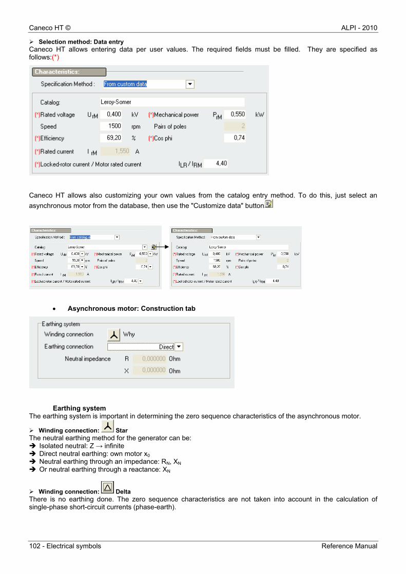
Caneco HT © ALPI - 2010
102 - Electrical symbols Reference Manual
Selection method: Data entry Caneco HT allows entering data per user values. The required fields must be filled. They are specified as follows:(*)
Caneco HT allows also customizing your own values from the catalog entry method. To do this, just select an
asynchronous motor from the database, then use the "Customize data" button
Asynchronous motor: Construction tab
Earthing system The earthing system is important in determining the zero sequence characteristics of the asynchronous motor.
Winding connection: Star The neutral earthing method for the generator can be: Isolated neutral: Z → infinite Direct neutral earthing: own motor x0 Neutral earthing through an impedance: RN, XN Or neutral earthing through a reactance: XN
Winding connection: Delta There is no earthing done. The zero sequence characteristics are not taken into account in the calculation of single-phase short-circuit currents (phase-earth).
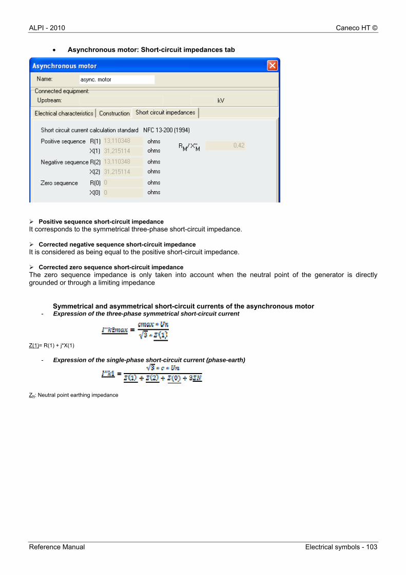
ALPI - 2010 Caneco HT ©
Reference Manual Electrical symbols - 103
Asynchronous motor: Short-circuit impedances tab
Positive sequence short-circuit impedance It corresponds to the symmetrical three-phase short-circuit impedance. Corrected negative sequence short-circuit impedance It is considered as being equal to the positive short-circuit impedance. Corrected zero sequence short-circuit impedance The zero sequence impedance is only taken into account when the neutral point of the generator is directly grounded or through a limiting impedance
Symmetrical and asymmetrical short-circuit currents of the asynchronous motor - Expression of the three-phase symmetrical short-circuit current
Z(1)= R(1) + j*X(1)
- Expression of the single-phase short-circuit current (phase-earth)
ZN: Neutral point earthing impedance
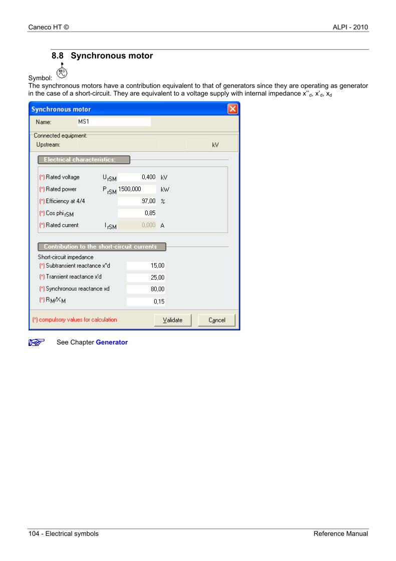
Caneco HT © ALPI - 2010
104 - Electrical symbols Reference Manual
8.8 Synchronous motor
Symbol: The synchronous motors have a contribution equivalent to that of generators since they are operating as generator in the case of a short-circuit. They are equivalent to a voltage supply with internal impedance x’’d, x’d, xd
See Chapter Generator
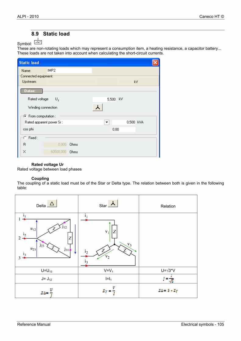
ALPI - 2010 Caneco HT ©
Reference Manual Electrical symbols - 105
8.9 Static load
Symbol: These are non-rotating loads which may represent a consumption item, a heating resistance, a capacitor battery... These loads are not taken into account when calculating the short-circuit currents.
Rated voltage Ur Rated voltage between load phases
Coupling The coupling of a static load must be of the Star or Delta type. The relation between both is given in the following table:
Delta
Star
Relation
U=U12 V=V1 U=√3*V
J= J12 I=I1
Caneco HT © ALPI - 2010
106 - Electrical symbols Reference Manual
Data associated with a static charge can be entered by way of calculation or equivalent impedance R and X (required):
Data entered by way of calculation The load rating as well as its cos phi (Pr/Sr ou R/Z) are entered. Data may be: Rated apparent power Sr (kVA) Rated active power Pr (kW) Rated reactive power Qr (kVAR) or rated current Ir (kA)
Required data The data to be entered are then equivalent impedance R and X under load rated voltage, which depends on the coupling.
8.10 Protections
Symbol: In Caneco HT, symbols of protection are only graphics and no characteristics can be entered in their window. They can be entered in the Link window, "Protection" tab
There are three types of loads 1) Constant impedance loads: the load varies as the square of the applied voltage.
E.g.: light bulbs, heating resistances, motor at start-up... The input current decreases if the terminal voltage decreases.
2) Constant power loads: steady-state motor, ballast lighting. The input currentincreases if the terminal voltage decreases.
3) Constant current loads: If the terminal voltage decreases, the apparent powerdecreases.
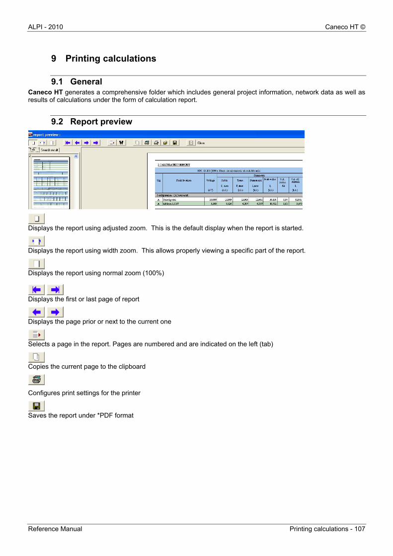
ALPI - 2010 Caneco HT ©
Reference Manual Printing calculations - 107
9 Printing calculations
9.1 General Caneco HT generates a comprehensive folder which includes general project information, network data as well as results of calculations under the form of calculation report.
9.2 Report preview
Displays the report using adjusted zoom. This is the default display when the report is started.
Displays the report using width zoom. This allows properly viewing a specific part of the report.
Displays the report using normal zoom (100%)
Displays the first or last page of report
Displays the page prior or next to the current one
Selects a page in the report. Pages are numbered and are indicated on the left (tab)
Copies the current page to the clipboard
Configures print settings for the printer
Saves the report under *PDF format

ALPI - 2010 Caneco HT ©
Reference Manual Glossary of the comprehensive folder - 109
10 Glossary of the comprehensive folder
10.1 Network data
10.1.1 Supply network
UnQ (kV) Nominal voltage between phases at the connection point Q to a supply by a network is specified and to which certain functional characteristics are related
S"kQmax (MVA) Initial short-circuit power at the connection point to supply Q It corresponds to the maximum current input from the three-phase short-circuit current of the public distribution network
S"kQmin (MVA) Initial short-circuit power at the connection point to supply Q min It corresponds to the minimum current input from the three-phase short-circuit current of the public distribution network
RQ/XQ Ratio between absolute resistance RQ and absolute reactance XQ of the supply system at the connection point Q
10.1.2 Synchronous generator
UrG (kV) Rated voltage between generator phases SrG (MVA) Rated apparent power of the synchronous generator x"d (%) Subtransient reactance relative to the rated impedance of a phased
synchronous machine (value at saturation) X"d (ohm) Absolute value of the rated subtransient reactance Cosφ rG Phase angle cosine between IrG and UrG/√3 RGf (ohm) Fictitious resistance of the generator used to calculate the peak value of
short-circuit current IrG (A) Rated current of the synchronous generator
10.1.3 Transformer
UrTHV (kV) Rated voltage of transformer on the high voltage side UrTLV (kV) Rated voltage of transformer on the low voltage side SrT (MVA) Rated apparent power of transformer Ukr (%) Short-circuit voltage for the rated current PkrT (kW) Total losses of the transformer windings related to the rated current IrTHV (A) Rated current of transformer on the high voltage side IrTLV (A) Rated current of transformer on the low voltage side
10.1.4 Static loads
Ur (kV) Rated voltage of static load Rc (ohm) Rated resistance of load Xc (ohm) Rated reactance of load
10.2 Calculation results
10.2.1 Short-circuit currents at boards
I"k3 subtransient (kA) Three-phase subtransient short-circuit current It corresponds to the rms value of the initial three-phase symmetrical component of a prospective short-circuit current
I'k3 subtransient (kA) Three-phase transient short-circuit current It corresponds to the rms value of the transient short-circuit current
I’k3 permanent (kA) Permanent three-phase short-circuit current

Caneco HT © ALPI - 2010
110 - Glossary of the comprehensive folder Reference Manual
It corresponds to the rms value of the short-circuit current that appears after the transient phenomenon
I"k1 subtransient (kA) Subtransient single-phase short-circuit current (phase-earth) It corresponds to the rms value of the initial three-phase symmetrical component of a prospective short-circuit current
I"k1 subtransient (kA) Subtransient short-circuit current Rms value of the initial short-circuit current which appears when a short-circuit between phase and earth occurs
îp subtransient (kA) Peak value of short-circuit current It corresponds to the maximum possible instantaneous value of the prospective short-circuit current
Ki Peak factor used to calculate the peak value of short-circuit current îp. Ib subtransient (kA) RMS value of the breaking symmetrical short-circuit current I'k2 subtransient (kA) RMS value of the symmetrical two-phase transient component Summary of calculations of cables according to withstand currents File File of available cable catalogs: Normative catalog, Pirelli, Prysmian,
Sagem catalog Cu /Alu Selecting the nature of the core: Copper or aluminum IB (A) Design intensity directly derived from the rated current of a powered
device, or a power requirement (loops) Iz Withstand current value determined according to the design current IB
while taking into account correction factors Laying method The laying method corresponds to the standard f1 Temperature correction factor
standard f2 Grouping of cables correction factor
standard f3 Ground resistivity correction factor
standard fc Overall resulting correction factor f1*f2*f3 fr Reduction factor which depends on the laying method. It is provided
according to Table BA - Practical guide standard
No. of cond. // Number of cables per phase SPH (mm²) Normalized cross-section of the phase conductor compliance Specifies whether the cable cross-section complies with the withstand
current criterion of standard, the possible letter F refers to the forcing of the cross-section If the forcing is too weak, Caneco indicates a "non-compliance" of the cable
Summary of calculations of cables according to thermal stress I’k2/3 transient Two-phase or three-phase transient short-circuit current depending on
the type of protection used: I’k3 for circuit-breaker protection, I’k2 for fuse protection,
Conf Calculated operating configuration Max switching time (ms)
Maximum working time of protection device or fuse melting time: pre-arc curve
I²t (kA²*s) Permissible thermal stress in conductors k Factor whose value is given in the standard Scalculated (mm²) Value of the calculated theoretical cross-section of conductors no. of cond. // Phase number of conductors SPH (mm²) Normalized cross-section of the phase conductor compliance Specifies whether the cable cross-section complies with the thermal
stress criterion of standard, the possible letter F refers to the forcing of the cross-section If the forcing is too weak, Caneco indicates a "non-compliance" of the cable If the "not checked" information is specified, this means that no protection is provided (link not "protected"), the section is then calculated for an arbitrary 1-second switching time
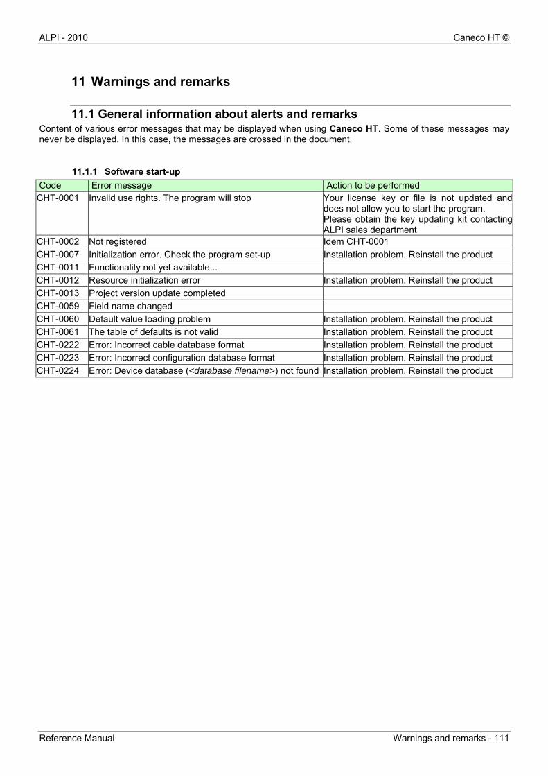
ALPI - 2010 Caneco HT ©
Reference Manual Warnings and remarks - 111
11 Warnings and remarks
11.1 General information about alerts and remarks Content of various error messages that may be displayed when using Caneco HT. Some of these messages may never be displayed. In this case, the messages are crossed in the document.
11.1.1 Software start-up
Code Error message Action to be performed CHT-0001 Invalid use rights. The program will stop Your license key or file is not updated and
does not allow you to start the program. Please obtain the key updating kit contacting ALPI sales department
CHT-0002 Not registered Idem CHT-0001
CHT-0007 Initialization error. Check the program set-up Installation problem. Reinstall the product
CHT-0011 Functionality not yet available...
CHT-0012 Resource initialization error Installation problem. Reinstall the product
CHT-0013 Project version update completed
CHT-0059 Field name changed
CHT-0060 Default value loading problem Installation problem. Reinstall the product
CHT-0061 The table of defaults is not valid Installation problem. Reinstall the product
CHT-0222 Error: Incorrect cable database format Installation problem. Reinstall the product
CHT-0223 Error: Incorrect configuration database format Installation problem. Reinstall the product
CHT-0224 Error: Device database (<database filename>) not found Installation problem. Reinstall the product
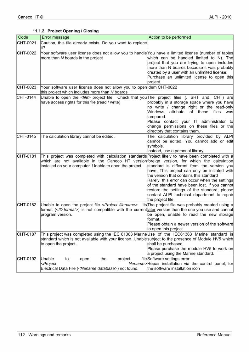
Caneco HT © ALPI - 2010
112 - Warnings and remarks Reference Manual
11.1.2 Project Opening / Closing
Code Error message Action to be performed CHT-0021 Caution, this file already exists. Do you want to replace
it?
CHT-0022 Your software user license does not allow you to handle more than N boards in the project
You have a limited license (number of tables which can be handled limited to N). The project that you are trying to open includes more than N boards because it was probably created by a user with an unlimited license. Purchase an unlimited license to open this project.
CHT-0023 Your software user license does not allow you to open this project which includes more than N boards
Idem CHT-0022
CHT-0144 Unable to open the <file> project file. Check that you have access rights for this file (read / write)
The project files (. SHT and. CHT) are probably in a storage space where you have no write / change right or the read-only Windows attribute of these files was tampered. Please contact your IT administrator to change permissions on these files or the directory that contains them.
CHT-0145 The calculation library cannot be edited. The calculation library provided by ALPI cannot be edited. You cannot add or edit symbols. Instead, use a personal library.
CHT-0181 This project was completed with calculation standards which are not available in the Caneco HT version installed on your computer. Unable to open the project.
Project likely to have been completed with a foreign version, for which the calculation standard is different from the version you have. This project can only be initiated with the version that contains this standard Rarely, this error can occur when the settings of the standard have been lost. If you cannot restore the settings of the standard, please contact ALPI technical department to repair the project file.
CHT-0182 Unable to open the project file <Project filename>. Its format (<ID format>) is not compatible with the current program version.
The project file was probably created using a later version than the one you use and cannot be open, unable to read the new storage format. Please obtain a newer version of the software to open this project.
CHT-0187 This project was completed using the IEC 61363 Marine standard which is not available with your license. Unable to open the project.
Use of the IEC61363 Marine standard is subject to the presence of Module HV5 which shall be purchased. Please purchase the module HV5 to work on a project using the Marine standard.
CHT-0192 Unable to open the project file <Project filename>Electrical Data File (<filename database>) not found.
Software settings error Repair installation via the control panel, for the software installation icon
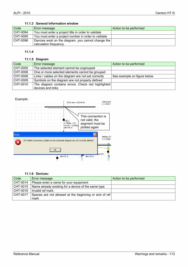
ALPI - 2010 Caneco HT ©
Reference Manual Warnings and remarks - 113
11.1.3 General Information window
Code Error message Action to be performed CHT-0094 You must enter a project title in order to validate CHT-0095 You must enter a project number in order to validate CHT-0096 Devices exist on the diagram, you cannot change the
calculation frequency.
11.1.4
11.1.5 Diagram
Code Error message Action to be performed CHT-0005 The selected element cannot be ungrouped CHT-0006 One or more selected elements cannot be grouped CHT-0008 Links / cables on the diagram are not set correctly See example on figure below CHT-0009 Symbols on the diagram are not properly defined CHT-0010 The diagram contains errors. Check red highlighted
devices and links
Example:
11.1.6 Devices:
Code Error message Action to be performed CHT-0014 Please enter a name for your equipment CHT-0015 Name already existing for a device of the same type CHT-0016 Invalid ref mark CHT-0017 Spaces are not allowed at the beginning or end of ref
mark
This connection is not valid, the segment must be plotted again
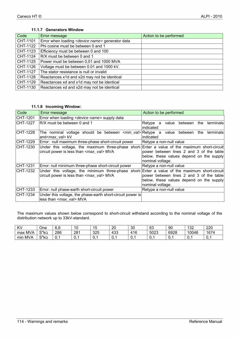
Caneco HT © ALPI - 2010
114 - Warnings and remarks Reference Manual
11.1.7 Generators Window
Code Error message Action to be performed CHT-1101 Error when loading <device name> generator data CHT-1122 Phi cosine must be between 0 and 1 CHT-1123 Efficiency must be between 0 and 100 CHT-1124 R/X must be between 0 and 1 CHT-1125 Power must be between 0,01 and 1000 MVA CHT-1126 Voltage must be between 0.01 and 1000 kV. CHT-1127 The stator resistance is null or invalid CHT-1128 Reactances x1d and x2d may not be identical CHT-1129 Reactances xd and x1d may not be identical CHT-1130 Reactances xd and x2d may not be identical
11.1.8 Incoming Window:
Code Error message Action to be performed CHT-1201 Error when loading <device name> supply data CHT-1227 R/X must be between 0 and 1 Retype a value between the terminals
indicated CHT-1228 The nominal voltage should be between <min_val>
and<max_val> kV Retype a value between the terminals indicated
CHT-1229 Error: null maximum three-phase short-circuit power Retype a non-null value CHT-1230 Under this voltage, the maximum three-phase short-
circuit power is less than <max_val> MVA Enter a value of the maximum short-circuit power between lines 2 and 3 of the table below, these values depend on the supply nominal voltage.
CHT-1231 Error: null minimum three-phase short-circuit power Retype a non-null value CHT-1232 Under this voltage, the minimum three-phase short-
circuit power is less than <max_val> MVA Enter a value of the maximum short-circuit power between lines 2 and 3 of the table below, these values depend on the supply nominal voltage.
CHT-1233 Error: null phase-earth short-circuit power Retype a non-null value CHT-1234 Under this voltage, the phase-earth short-circuit power is
less than <max_val> MVA
The maximum values shown below correspond to short-circuit withstand according to the nominal voltage of the distribution network up to 33kV-standard.
KV One 6,6 10 15 20 30 63 90 132 220 max MVA S"kQ 286 281 325 433 416 5023 6928 10046 1674 min MVA S"kQ 0,1 0,1 0,1 0,1 0,1 0,1 0,1 0,1 0,1
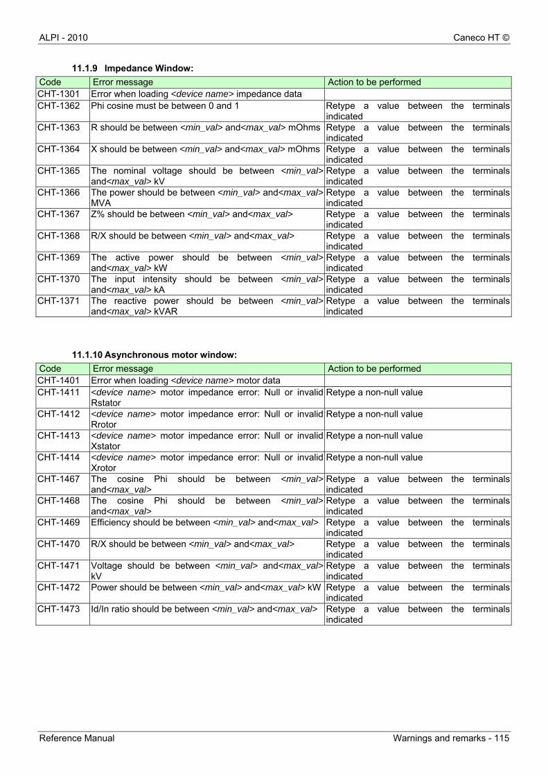
ALPI - 2010 Caneco HT ©
Reference Manual Warnings and remarks - 115
11.1.9 Impedance Window:
Code Error message Action to be performed CHT-1301 Error when loading <device name> impedance data CHT-1362 Phi cosine must be between 0 and 1 Retype a value between the terminals
indicated CHT-1363 R should be between <min_val> and<max_val> mOhms Retype a value between the terminals
indicated CHT-1364 X should be between <min_val> and<max_val> mOhms Retype a value between the terminals
indicated CHT-1365 The nominal voltage should be between <min_val>
and<max_val> kV Retype a value between the terminals indicated
CHT-1366 The power should be between <min_val> and<max_val>MVA
Retype a value between the terminals indicated
CHT-1367 Z% should be between <min_val> and<max_val> Retype a value between the terminals indicated
CHT-1368 R/X should be between <min_val> and<max_val> Retype a value between the terminals indicated
CHT-1369 The active power should be between <min_val>and<max_val> kW
Retype a value between the terminals indicated
CHT-1370 The input intensity should be between <min_val>and<max_val> kA
Retype a value between the terminals indicated
CHT-1371 The reactive power should be between <min_val>and<max_val> kVAR
Retype a value between the terminals indicated
11.1.10 Asynchronous motor window:
Code Error message Action to be performed CHT-1401 Error when loading <device name> motor data CHT-1411 <device name> motor impedance error: Null or invalid
Rstator Retype a non-null value
CHT-1412 <device name> motor impedance error: Null or invalid Rrotor
Retype a non-null value
CHT-1413 <device name> motor impedance error: Null or invalid Xstator
Retype a non-null value
CHT-1414 <device name> motor impedance error: Null or invalid Xrotor
Retype a non-null value
CHT-1467 The cosine Phi should be between <min_val>and<max_val>
Retype a value between the terminalsindicated
CHT-1468 The cosine Phi should be between <min_val>and<max_val>
Retype a value between the terminals indicated
CHT-1469 Efficiency should be between <min_val> and<max_val> Retype a value between the terminals indicated
CHT-1470 R/X should be between <min_val> and<max_val> Retype a value between the terminals indicated
CHT-1471 Voltage should be between <min_val> and<max_val>kV
Retype a value between the terminals indicated
CHT-1472 Power should be between <min_val> and<max_val> kW Retype a value between the terminals indicated
CHT-1473 Id/In ratio should be between <min_val> and<max_val> Retype a value between the terminals indicated
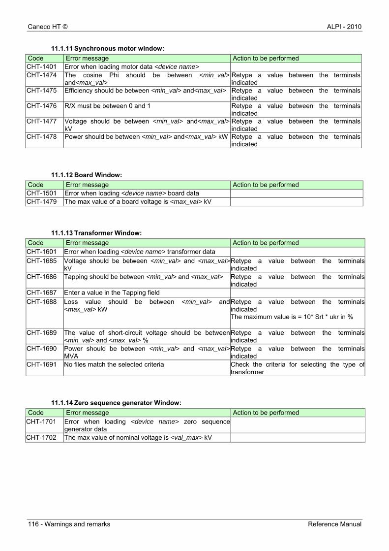
Caneco HT © ALPI - 2010
116 - Warnings and remarks Reference Manual
11.1.11 Synchronous motor window:
Code Error message Action to be performed CHT-1401 Error when loading motor data <device name> CHT-1474 The cosine Phi should be between <min_val>
and<max_val> Retype a value between the terminals indicated
CHT-1475 Efficiency should be between <min_val> and<max_val> Retype a value between the terminals indicated
CHT-1476 R/X must be between 0 and 1 Retype a value between the terminals indicated
CHT-1477 Voltage should be between <min_val> and<max_val>kV
Retype a value between the terminals indicated
CHT-1478 Power should be between <min_val> and<max_val> kW Retype a value between the terminals indicated
11.1.12 Board Window:
Code Error message Action to be performed CHT-1501 Error when loading <device name> board data CHT-1479 The max value of a board voltage is <max_val> kV
11.1.13 Transformer Window:
Code Error message Action to be performed CHT-1601 Error when loading <device name> transformer data
CHT-1685 Voltage should be between <min_val> and <max_val>kV
Retype a value between the terminals indicated
CHT-1686 Tapping should be between <min_val> and <max_val> Retype a value between the terminals indicated
CHT-1687 Enter a value in the Tapping field
CHT-1688 Loss value should be between <min_val> and <max_val> kW
Retype a value between the terminals indicated The maximum value is = 10* Srt * ukr in %
CHT-1689 The value of short-circuit voltage should be between <min_val> and <max_val> %
Retype a value between the terminals indicated
CHT-1690 Power should be between <min_val> and <max_val>MVA
Retype a value between the terminals indicated
CHT-1691 No files match the selected criteria Check the criteria for selecting the type of transformer
11.1.14 Zero sequence generator Window:
Code Error message Action to be performed CHT-1701 Error when loading <device name> zero sequence
generator data
CHT-1702 The max value of nominal voltage is <val_max> kV
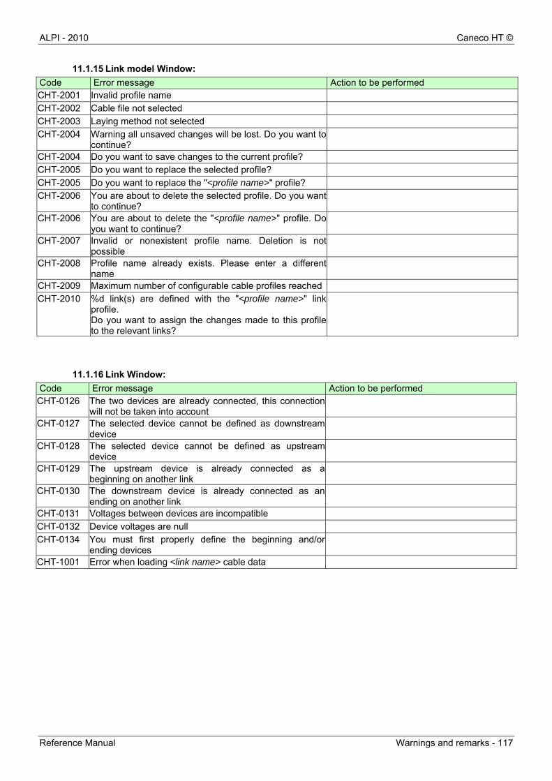
ALPI - 2010 Caneco HT ©
Reference Manual Warnings and remarks - 117
11.1.15 Link model Window:
Code Error message Action to be performed CHT-2001 Invalid profile name
CHT-2002 Cable file not selected
CHT-2003 Laying method not selected
CHT-2004 Warning all unsaved changes will be lost. Do you want to continue?
CHT-2004 Do you want to save changes to the current profile?
CHT-2005 Do you want to replace the selected profile?
CHT-2005 Do you want to replace the "<profile name>" profile?
CHT-2006 You are about to delete the selected profile. Do you want to continue?
CHT-2006 You are about to delete the "<profile name>" profile. Do you want to continue?
CHT-2007 Invalid or nonexistent profile name. Deletion is not possible
CHT-2008 Profile name already exists. Please enter a different name
CHT-2009 Maximum number of configurable cable profiles reached
CHT-2010 %d link(s) are defined with the "<profile name>" link profile. Do you want to assign the changes made to this profile to the relevant links?
11.1.16 Link Window:
Code Error message Action to be performed CHT-0126 The two devices are already connected, this connection
will not be taken into account
CHT-0127 The selected device cannot be defined as downstream device
CHT-0128 The selected device cannot be defined as upstream device
CHT-0129 The upstream device is already connected as a beginning on another link
CHT-0130 The downstream device is already connected as an ending on another link
CHT-0131 Voltages between devices are incompatible
CHT-0132 Device voltages are null
CHT-0134 You must first properly define the beginning and/or ending devices
CHT-1001 Error when loading <link name> cable data
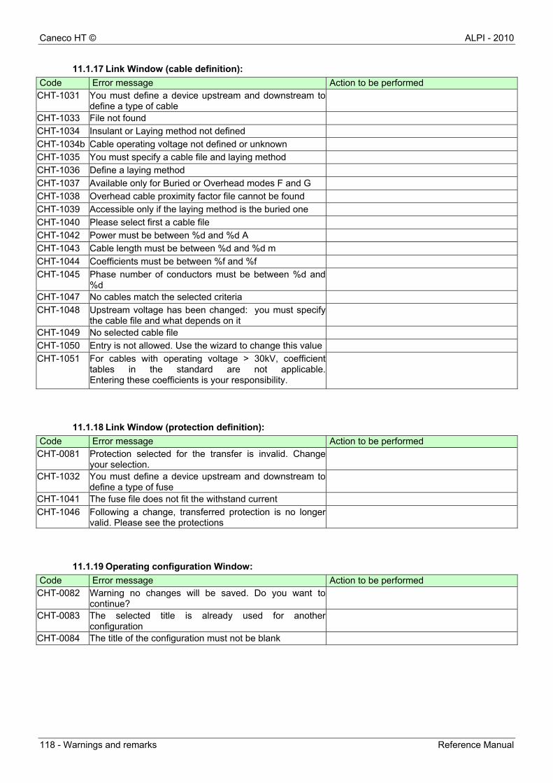
Caneco HT © ALPI - 2010
118 - Warnings and remarks Reference Manual
11.1.17 Link Window (cable definition):
Code Error message Action to be performed CHT-1031 You must define a device upstream and downstream to
define a type of cable
CHT-1033 File not found
CHT-1034 Insulant or Laying method not defined
CHT-1034b Cable operating voltage not defined or unknown
CHT-1035 You must specify a cable file and laying method
CHT-1036 Define a laying method
CHT-1037 Available only for Buried or Overhead modes F and G
CHT-1038 Overhead cable proximity factor file cannot be found
CHT-1039 Accessible only if the laying method is the buried one
CHT-1040 Please select first a cable file
CHT-1042 Power must be between %d and %d A
CHT-1043 Cable length must be between %d and %d m
CHT-1044 Coefficients must be between %f and %f
CHT-1045 Phase number of conductors must be between %d and %d
CHT-1047 No cables match the selected criteria
CHT-1048 Upstream voltage has been changed: you must specify the cable file and what depends on it
CHT-1049 No selected cable file
CHT-1050 Entry is not allowed. Use the wizard to change this value
CHT-1051 For cables with operating voltage > 30kV, coefficient tables in the standard are not applicable. Entering these coefficients is your responsibility.
11.1.18 Link Window (protection definition):
Code Error message Action to be performed CHT-0081 Protection selected for the transfer is invalid. Change
your selection.
CHT-1032 You must define a device upstream and downstream to define a type of fuse
CHT-1041 The fuse file does not fit the withstand current
CHT-1046 Following a change, transferred protection is no longer valid. Please see the protections
11.1.19 Operating configuration Window:
Code Error message Action to be performed CHT-0082 Warning no changes will be saved. Do you want to
continue?
CHT-0083 The selected title is already used for another configuration
CHT-0084 The title of the configuration must not be blank

ALPI - 2010 Caneco HT ©
Reference Manual Warnings and remarks - 119
11.1.20 Calculation procedure:
Code Error message Action to be performed CHT-0003 Calculation error. Check the links and devices
CHT-0003 Error when calculating "<calculation type>".
CHT-0004 Error in the calculation procedure.
CHT-0018 calculation error (see the log)
CHT-0019 Calculation of intensity not done: one of your parameters is null
CHT-0020 See the log
CHT-0051 Calculation not possible! The network must include at least one incoming feeder Check the connections between the production device and the network
Check that at least one link wich connects an incoming feeder or a production device to the network is active in the operating configuration being calculated
CHT-0052 Required "upstream" and "downstream" devices of the <link name> link
CHT-0053 <link name>, <filename> cable file cannot be found Calculation not possible.
CHT-0054 <name> cannot be found
CHT-0055 Link between "<device name>" and "<device name>" (<link name>): operating voltages of devices aer different. Calculation not possible
CHT-0056 Ddifferent voltages: <link name>
CHT-0057 Error in the composition of the operating configuration <configuration code>
See explanations “Error in the composition ofthe operating configuration”, after this table
CHT-0058 You must select at least one operating configuration
CHT-0062 Error in the composition of the calculation matrix (size NxM)
CHT-0080 The cable file must be changed
CHT-0100 Error in the calculation model construction.
CHT-0101 Calculation not possible in the operating configuration "<configuration code>". Check for a closed loop (not calculable with IEC 61363) and delete it from the operating configuration
CHT-0104 A calculation is already running. Please close the results window to continue.
CHT-0105 Searching max nominal current
CHT-0106 Error when calculating nominal current: <device name>
CHT-0107 Error when calculating impedances: <device name>
CHT-0108 Error when calculating cable cross-section and number of conductors: <link name>
CHT-0109 Error when calculating static load impedances: <device name>
CHT-0110 Error when searching next cable
CHT-0111 Error when calculating fuse rating
CHT-0112 The beginning or ending was not specified
CHT-0113 Cable file has not been allocated or does not exist
CHT-0114 The result is not significant: the cross-section shown is the most general
CHT-0115 The result is not significant: phase cross-section cannot be calculated
CHT-0116 the required cross-section is smaller than the calculated cross-section
CHT-0117 Voltage is null
CHT-0118 Power is null
CHT-0119 Losses should not exceed: <max_val>
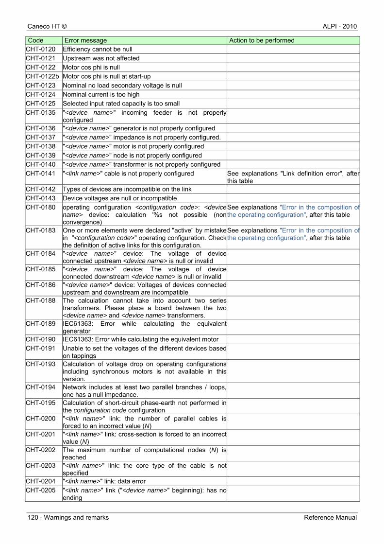
Caneco HT © ALPI - 2010
120 - Warnings and remarks Reference Manual
Code Error message Action to be performed CHT-0120 Efficiency cannot be null
CHT-0121 Upstream was not affected
CHT-0122 Motor cos phi is null
CHT-0122b Motor cos phi is null at start-up
CHT-0123 Nominal no load secondary voltage is null
CHT-0124 Nominal current is too high
CHT-0125 Selected input rated capacity is too small
CHT-0135 "<device name>" incoming feeder is not properly configured
CHT-0136 "<device name>" generator is not properly configured
CHT-0137 "<device name>" impedance is not properly configured.
CHT-0138 "<device name>" motor is not properly configured
CHT-0139 "<device name>" node is not properly configured
CHT-0140 "<device name>" transformer is not properly configured
CHT-0141 "<link name>" cable is not properly configured See explanations "Link definition error", after this table
CHT-0142 Types of devices are incompatible on the link
CHT-0143 Device voltages are null or incompatible
CHT-0180 operating configuration <configuration code>: <device name> device: calculation '%s not possible (non convergence)
See explanations "Error in the composition ofthe operating configuration", after this table
CHT-0183 One or more elements were declared "active" by mistake in "<configuration code>" operating configuration. Check the definition of active links for this configuration.
See explanations "Error in the composition ofthe operating configuration", after this table
CHT-0184 "<device name>" device: The voltage of device connected upstream <device name> is null or invalid
CHT-0185 "<device name>" device: The voltage of device connected downstream <device name> is null or invalid
CHT-0186 "<device name>" device: Voltages of devices connected upstream and downstream are incompatible
CHT-0188 The calculation cannot take into account two series transformers. Please place a board between the two <device name> and <device name> transformers.
CHT-0189 IEC61363: Error while calculating the equivalent generator
CHT-0190 IEC61363: Error while calculating the equivalent motor
CHT-0191 Unable to set the voltages of the different devices based on tappings
CHT-0193 Calculation of voltage drop on operating configurations including synchronous motors is not available in this version.
CHT-0194 Network includes at least two parallel branches / loops, one has a null impedance.
CHT-0195 Calculation of short-circuit phase-earth not performed in the configuration code configuration
CHT-0200 "<link name>" link: the number of parallel cables is forced to an incorrect value (N)
CHT-0201 "<link name>" link: cross-section is forced to an incorrect value (N)
CHT-0202 The maximum number of computational nodes (N) is reached
CHT-0203 "<link name>" link: the core type of the cable is not specified
CHT-0204 "<link name>" link: data error
CHT-0205 "<link name>" link ("<device name>" beginning): has no ending
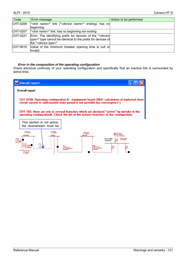
ALPI - 2010 Caneco HT ©
Reference Manual Warnings and remarks - 121
Code Error message Action to be performed CHT-0206 "<link name>" link ("<device name>" ending): has no
beginning
CHT-0207 "<link name>" link: has no beginning nor ending
CHT-0221 Error: The identifying prefix for devices of the "<device type>" type cannot be identical to the prefix for devices of the "<device type>"
CHT-9010 Value of the minimum breaker opening time is null or invalid.
Error in the composition of the operating configuration Check electrical continuity of your operating configuration and specifically that an inactive link is surrounded by active links.
This section is not active, the downstream must be

Caneco HT © ALPI - 2010
122 - Warnings and remarks Reference Manual
Link definition error
Check that the cable characteristics are properly entered: General information and protections entry fields
Example below: window not completed.
Check that the cable ref mark on which protection is "transferred" is properly identified
Example:
Identify the protection on which this link is protected by activating the button
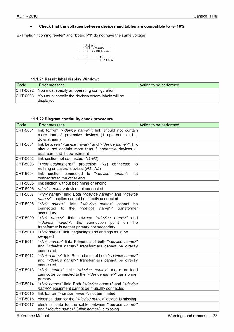
ALPI - 2010 Caneco HT ©
Reference Manual Warnings and remarks - 123
Check that the voltages between devices and tables are compatible to +/- 10% Example: "incoming feeder" and "board P1" do not have the same voltage.
11.1.21 Result label display Window:
Code Error message Action to be performed CHT-0092 You must specify an operating configuration
CHT-0093 You must specify the devices where labels will be displayed
11.1.22 Diagram continuity check procedure
Code Error message Action to be performed CHT-5001 link to/from "<device name>": link should not contain
more than 2 protective devices (1 upstream and 1 downstream)
CHT-5001 link between "<device name>" and "<device name>": link should not contain more than 2 protective devices (1 upstream and 1 downstream)
CHT-5002 link section not connected (N1-N2)
CHT-5003 "<nom équipement>" protection (N1) connected to nothing or several devices (N1 –N2)
CHT-5004 link section connected to "<device name>": not connected to the other end
CHT-5005 link section without beginning or ending
CHT-5006 <device name> device not connected
CHT-5007 "<link name>" link: Both "<device name>" and "<device name>" supplies cannot be directly connected
CHT-5008 "<link name>" link: "<device name>" cannot be connected to the "<device name>" transformer secondary
CHT-5009 "<link name>" link between "<device name>" and "<device name>": the connection point on the transformer is neither primary nor secondary
CHT-5010 "<link name>" link: beginnings and endings must be swapped
CHT-5011 "<link name>" link: Primaries of both "<device name>" and "<device name>" transformers cannot be directly connected
CHT-5012 "<link name>" link: Secondaries of both "<device name>" and "<device name>" transformers cannot be directly connected
CHT-5013 "<link name>" link: "<device name>" motor or load cannot be connected to the "<device name>" transformer primary
CHT-5014 "<link name>" link: Both "<device name>" and "<device name>" equipment cannot be mutually connected
CHT-5015 link to/from "<device name>": not terminated
CHT-5016 electrical data for the "<device name>" device is missing
CHT-5017 electrical data for the cable between "<device name>" and "<device name>" (<link name>) is missing
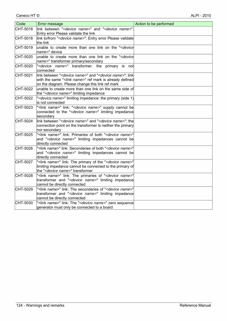
Caneco HT © ALPI - 2010
124 - Warnings and remarks Reference Manual
Code Error message Action to be performed CHT-5018 link between "<device name>" and "<device name>":
Entry error Please validate the link
CHT-5018 link to/from "<device name>": Entry error Please validate the link
CHT-5019 unable to create more than one link on the "<device name>" device
CHT-5020 unable to create more than one link on the "<device name>" transformer primary/secondary
CHT-5020 "<device name>" transformer: the primary is not connected
CHT-5021 link between "<device name>" and "<device name>": link with the same "<link name>" ref mark is already defined on the diagram. Please change this link ref mark
CHT-5022 unable to create more than one link on the same side of the "<device name>" limiting impedance
CHT-5022 "<device name>" limiting impedance: the primary (side 1) is not connected
CHT-5023 "<link name>" link: "<device name>" supply cannot be connected to the "<device name>" limiting impedance secondary
CHT-5024 link between "<device name>" and "<device name>": the connection point on the transformer is neither the primary nor secondary
CHT-5025 "<link name>" link: Primaries of both "<device name>" and "<device name>" limiting impedances cannot be directly connected
CHT-5026 "<link name>" link: Secondaries of both "<device name>" and "<device name>" limiting impedances cannot be directly connected
CHT-5027 "<link name>" link: The primary of the "<device name>" limiting impedance cannot be connected to the primary of the "<device name>" transformer
CHT-5028 "<link name>" link: The primaries of "<device name>" transformer and "<device name>" limiting impedance cannot be directly connected
CHT-5029 "<link name>" link: The secondaries of "<device name>" transformer and "<device name>" limiting impedance cannot be directly connected
CHT-5030 "<link name>" link: The "<device name>" zero sequence generator must only be connected to a board

ALPI - 2010 Caneco HT ©
Reference Manual Index - 125
Index
C
Calculation repository EN 60909-0.................................................................. 14 NFC 13-200 ................................................................. 14 Practical guide UTE 13-200 ......................................... 14
Calculation tools command Comprehensive calculation.......................................... 21 List of devices .............................................................. 21 List of links ................................................................... 21 Short-circuit current calculation.................................... 21 Voltage drop calculation............................................... 21
D
Database Directory Base............................................................................. 11 InstallKey ..................................................................... 12 Lib ................................................................................ 11 LocalCache.................................................................. 12 Projects........................................................................ 12 Templates .................................................................... 11
Definition Device.......................................................................... 14 Link .............................................................................. 14
Display menu Data label..................................................................... 50 Result label .................................................................. 51 Zoom............................................................................ 52
Drawing tools command Arc ............................................................................... 20 Cursor .......................................................................... 19 Dynamic zoom ............................................................. 19 Ellipse .......................................................................... 20 Layer manager............................................................. 20 Layers .......................................................................... 20 Line.............................................................................. 20 Polygon........................................................................ 20 Polyline ........................................................................ 20 Rectangle..................................................................... 20 Text.............................................................................. 19 Zoom factor.................................................................. 19
E
Edit command Adjust on grid ........................................... 18 Edit command Clear ........................................................ 18 Edit command Copy ........................................................ 18 Edit command Copy with layers....................................... 18 Edit command Cut ........................................................... 18 Edit command Display grid .............................................. 18 Edit command Find.......................................................... 18 Edit command Ortho mode .............................................. 18 Edit command Parameters .............................................. 18 Edit command Paste........................................................ 18 Edit menu
Arc tool......................................................................... 45 Clear ............................................................................ 24 Copy ............................................................................ 24 Cut ............................................................................... 24 Ellipse tool ................................................................... 46 Find.............................................................................. 24
Insert an image.............................................................47 Insert element...............................................................45 Insert tool......................................................................47 Line tool........................................................................45 Polygon tool..................................................................46 Polyline tool ..................................................................46 Rectangle tool ..............................................................46 Select ...........................................................................44 Symbol tool...................................................................46 Text tool........................................................................47
Electrical link tool command Link...............................................................................21
Electrical symbols Asynchronous motor...................................................102 Board............................................................................96 Generator .....................................................................90 Incoming feeder............................................................85 Protections .................................................................108 Static loads.................................................................107 Synchronous motor ....................................................106 Three-winding transformers........................................101 Two-winding transformer ..............................................97 Zero sequence generator .............................................96
F
File command New ..............................................................................17 Open.............................................................................17 Save .............................................................................17
File menu Close ............................................................................36 Exit ...............................................................................23 Export ...........................................................................36 New ..............................................................................23 Open.............................................................................23 Print ..............................................................................36 Print preview.................................................................36 Print Setup....................................................................36 Save .............................................................................35 Send .............................................................................36
G
Group of objects command Background ..................................................................20 Foreground...................................................................20 Group ...........................................................................20 Ungroup........................................................................20
H
Help menu About ............................................................................80 Contents .......................................................................80 Self-training manual......................................................80
L
Library command Library ..........................................................................18
Caneco HT © ALPI - 2010
126 - Index Reference Manual
M
Menu bar Symbols library area .................................................... 16 Workspace................................................................... 16
Menu commands Pop-up menus ............................................................. 17
Modify menu Align............................................................................. 49 Center .......................................................................... 49 Distribute...................................................................... 49 Edit symbol .................................................................. 48 Flip ............................................................................... 49 Group........................................................................... 49 Order............................................................................ 48 Parameters .................................................................. 48 Rotate .......................................................................... 49 Size.............................................................................. 49 Transformation............................................................. 48 Ungroup ....................................................................... 49
O
Option menu Configuration ............................................................... 30 Database ..................................................................... 29 Preferences ................................................................. 27
P
Print command Print ............................................................................. 18 Print preview ................................................................ 18
Printing calculations Report preview........................................................... 109
Project menu Adjust on grid............................................................... 78 Calculation Options...................................................... 57 Comprehensive folder.................................................. 75 Diagram continuity check............................................. 60 Display configuration.................................................... 64 Display grid .................................................................. 78 General information about the project.......................... 55 Ik calculations .............................................................. 66 Layers .......................................................................... 78 Link template ............................................................... 59
List of devices...............................................................65 List of links....................................................................65 Operating configurations ..............................................62 Ortho mode ..................................................................78 Parameters...................................................................77 Style .............................................................................78 Summary of cables.......................................................69 Voltage drop .................................................................76
Purpose of the software Designing an installation...............................................13
R
Rotation command Flip horizontally ............................................................19 Flip vertically.................................................................19 Rotate left .....................................................................19 Rotate right...................................................................19
S
Software description HV1 module:.................................................................13 HV2 module..................................................................13 HV3 module..................................................................13 HV4 module..................................................................13 HV5 Module..................................................................13 HV6 Module..................................................................13
Symbol menu Add...............................................................................25 Edit ...............................................................................25 Move up, Move down ...................................................25 Parameters...................................................................25
Symbols library Attributes and descriptions ...........................................82 Create a symbol ...........................................................83 Overview ......................................................................81
W
Window menu Cascade .......................................................................79 Close ............................................................................79 Tile................................................................................79

REFERENCE MANUAL
Calculation and diagrams
for High Voltage electrical installations
Ca
nec
o H
T
1, bd Charles de Gaulle
F-92700 COLOMBES - FRANCE
Tel: +33 (0)1 47 52 97 27
Fax: +33 (0)1 47 52 95 60
E-mail : [email protected] - web : www.caneco.eu
Refe
renc
e m
anua
l