Aluminium Slab Formwork
12
// Table of content Features Benefits Solutions Basic components 2 5 8 11 CC-4 Aluminium Slab Formwork // Light, safe, highly efficient and excellent concrete finish
Transcript of Aluminium Slab Formwork

// Table of content FeaturesBenefitsSolutions Basic components
258
11
CC-4 Aluminium Slab Formwork
// Light, safe, highly efficient and excellent concrete finish

2
CC-4 Aluminium Slab Formwork
// Features
Recoverable formwork system for solid and lightened slabs ensuring high quality finish.
Quick erection and dismantling due to aluminium structure and fast striking system and complying with highest safety standards for the worker.
Safe stripping due to drop-down system to lower the formwork (drop distance 15 cm).
Different assembly types: with panel (aluminium frame with incorporated board) or with standard plywood.
Sequence of drophead for striking
Pouring position Striking position
Hitting the wedge Turn of the wedge Drop of the wedge Drop of the formwork

3
1
2
1,5
m
2,17 m
Viga CC 1,57
1,57 m
Viga CC 2,32
Panel CC 1,5 x 0,75
Panel CC 0,75 x 0,75
Transversal CC TE 0,75
Cabezal CC
0,75
m
0,75
m
2,44 m
1,74 m
1,57 m
Transversal CC TE 1,5
Transversal CC TE 0,75Viga CC 1,57
CC-4 Aluminium Slab Formwork
Maximum slab thickness
Grid (m)Maximum slab thickness (cm)
2.32 x 1.5 40
1.57 x 1.5 60
2.32 x 0.75 90
1.57 x 0.75 90
Perfect for large slabs in building construction, with regular geometry and spans between columns, and high demands for finishing quality.
Consisting of Dropheads CC, Beams CC, Transversals CC TE and Panels CC; panels make up the biggest part of the form face. 1 Transversal CC TE
2 Panels
With the basic grid 2.32 m x 1.5 m, a prop rate of 0.29 props/m2 can be achieved.
Excellent concrete finishing: watertight joints between panels that inhibit concrete leaking.
CC-4 Panel system properties:
Customised grid sizes can be configured by combining beams and transversals .
CC-4 Panel system basic grid
Panel CC
Drophead CC
Transversal CC TE
Beam CC
CC-4 PANEL SYSTEM

4
CC-4 Aluminium Slab Formwork
Designed for any slab geometry and high demands on finishing quality.
Form face: grid of Dropheads CCT, Beams CC, Transversals CC TR and plywood.
The dropheads allow recovering beams, transversals and plywood.
Great flexibility.
CC-4 PLY SYSTEM
Board
Drophead CCT
Transversal CC TR
Beam CC

5
CC-4 Aluminium Slab Formwork
Lightness: High assembly efficiency.
The form face provides superior concrete finishing.
Stripping and material retrieval without the risk of falls: highest worker’s protection.
Formwork recoverable in 3 days, only the props with Dropheads CC remain as load-bearing items.
It allows the assembly of the grid previously to the placing of panels or plywood.
Great versatility: it allows a change in beam direction, 90° assembly possible.
Slabs of up to 90 cm thickness, depending on grid size in use.
Efficient solutions for infills at columns and walls, perimeter protection and safety.
Safe panel assembly from below, from a single position, several grids are completed by sliding the panels into place.
There are pallets for shipping and transport on site of beams and panels available.
// Benefits
Recoverable structure
Remaining structure

6
CC-4 Aluminium Slab Formwork
Grid structure erection
Striking with drophead Change of beam direction
High assembly efficiency for large slabs
Several teams for the assembly of grids and panels can work at once

7
CC-4 Aluminium Slab Formwork
Safe panel assembly from below
Safe dismantling
Pallets for panels
Pallet for beams easing their transport
Shuttering face with phenolic plywood or composite board
8
CC-4 Aluminium Slab Formwork
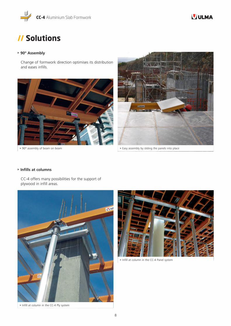
// Solutions
90º Assembly
Change of formwork direction optimises its distribution and eases infills.
Infills at columns
CC-4 offers many possibilities for the support of plywood in infill areas.
Easy assembly by sliding the panels into place 90º assembly of beam on beam
Infill at column in the CC-4 Panel system
Infill at column in the CC-4 Ply system

9
CC-4 Aluminium Slab Formwork
Infill at wall in the CC-4 Ply system
Beams VM on props that provide support for the infill plywood
Solutions between walls
Wide variety starting-from-a-wall and infills at walls solutions in both formwork directions.
Starting-from-a-wall with panel at the edge Infills at walls with edge beam as infill plywood support

10
CC-4 Aluminium Slab Formwork
Perimeter formwork
It eases the lateral forming of the slab, the placing of the stop-end and provides a perimeter working area.
Perimeter protection
Complete safety with handrails easily installed at the perimeter and at voids.
Column heads Lightened slab

11
CC-4 Aluminium Slab Formwork
Drophead CC 1870060 4.9
Universal head CC 1870500 3.7
Drophead CCT 1870155 4.6
Panel CC 1.5x0.75 1870090 15.4
Panel CC 1.5x0.375 1870165 9.1
Panel CC 0.75x0.75 1870096 8.3
Panel CC 0.75x0.375 1870265 4.7
Panel CC 1.5x0.75 EVERMAX 1870290 15.4
Panel CC 0.75x0.75 EVERMAX 1870296 8.3
Panel CC 1.5x0.375 EVERMAX 1870365 9.1
Panel CC 0.75x0.375 EVERMAX 1870565 4.7
Edge beam 2.32 1870464 8.9
Edge beam 1.57 1870465 5.7
Edge beam 0.82 1870466 2.7
Beam CC W 2.075 1870230 12.4
Beam CC W 1.5 1870105 8.9
Beam CC W 0.75 1870150 4.4
Beam CC W 0.375 1870375 2.1
Maxi pallet CC panels 1870300 95
Beam CC 2.32 1870029 16
Beam CC 1.57 1870031 10.6
Transversal CC TE 1.5 ALU 1870400 5.3
Transversal CC TE 0.75 ALU 1870405 2.7
Transversal CC TE 0.375 ALU 1870407 1.4
Transversal CC TR 2.075 1870225 8.7
Transversal CC TR 1.5 1870045 6.3
Transversal CC TR 0.75 1870050 3.2
kg kgkg
Basic components

www.ulmaconstruction.com
ULMA C y E, S. Coop.Ps. Otadui, 3 - P.O. 1320560 Oñati, SpainT. +34 943 034 900F. +34 943 034 920
Any safety provisions as directed by the appropriate governing agencies must be observed when using our products. The pictures in this document are snapshots of situations at different stages of assembly, and therefore are not complete images. For the purpose of safety, they should not be deemed as definitive. All of the indications regarding safety and operations contained in this document, and the data on stress and loads should be respected. ULMA’s Technical Department must be consulted anytime that field changes alter our equipment installation drawings. The loads featured in this document, related to the basic elements of the product, are approximate. Our equipment is designed to work with accessories and elements made by our company only. Combining such equipment with other systems is not only dangerous but also voids any or all our warrantees. The company
reserves the right to introduce any modifications deemed necessary for the technical development of the product. All rights reserved. Neither all nor part of this document may be reproduced or transmitted in any way by any electronic or mechanical procedure, including photocopy, magnetic recording or any other form of information storage or retrieval system without the written permission.
© Copyright by ULMA C y E, S. Coop
IMPORTANT:
02B172ENM