
MULTIPROP System Instructions for Assembly and Use -...
54
MULTIPROP System Instructions for Assembly and Use – Standard Configuration - Issue 04/2018 UK Edition 04|2019
Transcript of MULTIPROP System Instructions for Assembly and Use -...
MULTIPROPSystem
Instructions for Assembly and Use – Standard Configuration - Issue 04/2018 UK Edition 04|2019
1
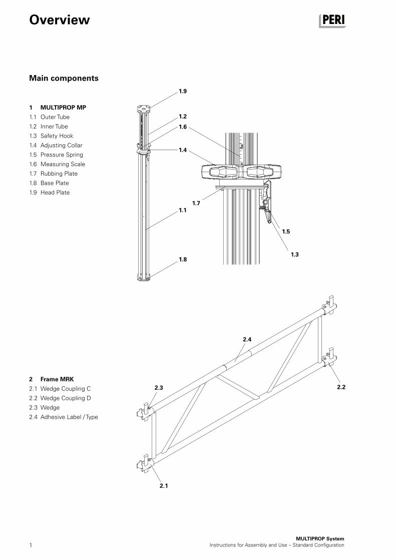
Main components
MULTIPROP SystemInstructions for Assembly and Use – Standard Configuration
Overview
1 MULTIPROP MP
1.1 Outer Tube
1.2 Inner Tube
1.3 Safety Hook
1.4 Adjusting Collar
1.5 Pressure Spring
1.6 Measuring Scale
1.7 Rubbing Plate
1.8 Base Plate
1.9 Head Plate
2 Frame MRK
2.1 Wedge Coupling C
2.2 Wedge Coupling D
2.3 Wedge
2.4 Adhesive Label / Type
1.9
1.2
1.6
1.4
1.71.1
1.8
1.5
1.3
2.22.3
2.4
2.1
ApplicationB1 Structural Scaffold Tube Bracings Scaffold Tube Coupling MG 35
B2 Frames Use as scaffold girder 36
B3 Tables and towers Lowering 37 Moving with the Trolley with Winch 37 Moving along with pole 38
Tables 38
Components Components 40
Overview Main components 1 Accessories 2 Key 3Introduction Target groups 4 Additional technical documentation 4 Intended use 5 Cleaning and maintenance instructions 6Safety instructions Cross-system 7 System-specific 8 Storage and transportation 8Foreseeable misapplications 9
Assembly and dismantlingA1 MULTIPROP Individual Prop Adjusting the extension length 10
A2 MULTIPROP System Connecting the props 11 Frame MRK 12 Compression Brace Head MP/SRU 14 Tilting Base MKF 15 Tilting Forkhead MKK 16 Base MP 50 17 A3 Horizontal assembly With 4 legs 18 With multiple number of legs 21 Erecting the tower 22
A4 Vertical assembly First level 24 Additional levels 25
A5 Bracing MULTIPROP Towers Installing the Brace Connector MPR 26 Support with Push-Pull Props 28 Supporting in units 29
A6 Accessories MULTIPROP Strap U100 – U140 30 Connecting MULTIPROP with MPB 24 30 Compression Brace Head MP/SRU with Connector MP/SRU 31
A7 Dismantling Vertical dismantling 32 Horizontal dismantling 33
A8 Storage and transportation 34
MULTIPROP SystemInstructions for Assembly and Use – Standard Configuration
Content
2MULTIPROP System
Instructions for Assembly and Use – Standard Configuration
Overview
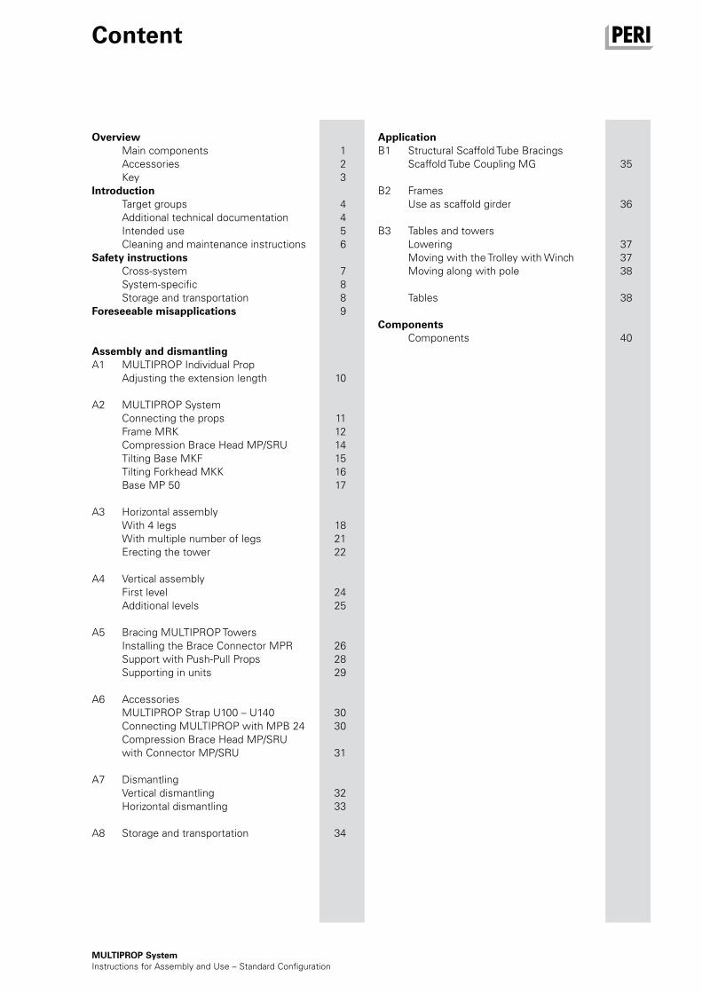
Accessories
3 Base MP 50
3.1 Head Plate
3.2 Clamping Claw
3.3 Centering Pin
4 Tilting Base MKF
4.1 Head Plate
4.2 Clamping Claw
4.3 Centering Pin
4.4 Wing Bolt
5 Tilting Forkhead MKK
5.1 Base Plate
5.2 Clamping Claw
5.3 Centering Pin
5.4 Wing Bolt
6 MULTIPROP Strap U100 - U140
6.1 Mounting Plate
6.2 Plate
6.3 Hex. Bolt M16
6.4 Hex. Nut M16, SW 24
7 Connector MPV-2
7.1 Connection Handle
7.2 Clamping Jaw
7.3 Centering Pin
8 MULTIPROP Bolt with Nut
8.1 Bolt M12
8.2 Nut M12
9 Compression Brace Head MP/SRU
9.1 Fitting Pin 21 with Cotter Pin
3.1
3.2
3.3
5.4
5.3
5.1
5.2
7.2
7.3
7.1
4.1 4.2
4.3
4.4
6.3
6.4
6.2
6.1
8.1
9.1
8.2
3MULTIPROP SystemInstructions for Assembly and Use – Standard Configuration
Overview
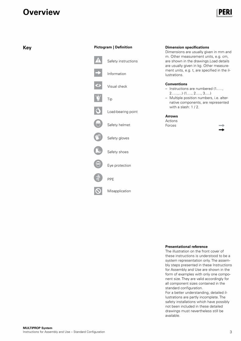
Key Dimension specificationsDimensions are usually given in mm and m. Other measurement units, e.g. cm, are shown in the drawings.Load details are usually given in kg. Other measure-ment units, e.g. t, are specified in the il-lustrations.
Conventions – Instructions are numbered (1......,
2......,...) (1....., 2....., 3.....) – Multiple position numbers, i.e. alter-
native components, are represented with a slash: 1 / 2.
ArrowsActionsForces
Presentational referenceThe illustration on the front cover of these instructions is understood to be a system representation only. The assem-bly steps presented in these Instructions for Assembly and Use are shown in the form of examples with only one compo-nent size. They are valid accordingly for all component sizes contained in the standard configuration.For a better understanding, detailed il-lustrations are partly incomplete. The safety installations which have possibly not been included in these detailed drawings must nevertheless still be available.
Safety instructions
Visual check
Load-bearing point
Safety helmet
Safety gloves
Safety shoes
Eye protection
PPE
Information
Tip
Pictogram | Definition
Misapplication
4MULTIPROP System
Instructions for Assembly and Use – Standard Configuration
Introduction
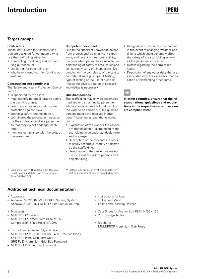
ContractorsThese Instructions for Assembly and Use are designed for contractors who use the scaffolding either for
assembling, modifying and disman-tling purposes, or
use it, e.g. for concreting, or who have it used, e.g. for forming op-erations.
Construction site coordinatorThe Safety and Health Protection Coordi-nator*
is appointed by the client, must identify potential hazards during the planning phase,
determines measures that provide protection against risks,
creates a safety and health plan, coordinates the protective measures for the contractor and site personnel so that they do not endanger each other,
monitors compliance with the protec-tive measures.
Target groups
Approvals: – Approval Z-8.22-802 MULTIPROP Shoring System – Approval Z-8.312-824 MULTIPROP Aluminium Prop
Type tests: – MULTIPROP System – MULTIPROP System with Base MP 50 – Compression Brace Head MP/SRU
Instructions for Assembly and Use: – MULTIPROP MP 120, 250, 350, 480, 625 Slab Props – SKYDECK Panel Slab Formwork – GRIDFLEX Aluminium Grid Slab Formwork – MULTIFLEX Girder Slab Formwork
Instructions for Use: – Trolley with Winch – Pallets and Stacking Devices
Data Sheet for Anchor Bolt PERI 14/20 x 130 PERI Design Tables
Brochure: – MULTIPROP Aluminium Slab Props
Additional technical documentation
* Valid in Germany: Regulations for Occupa-tional Health and Safety on Construction Sites 30 (RAB 30).
** Instructions are given by the contractor him-self or a competent person selected by him.
Competent personnelDue to the specialist knowledge gained from professional training, work experi-ence, and recent professional activity, the competent person has a reliable un-derstanding of safety-related issues and can correctly carry out inspections. De-pending on the complexity of the test to be undertaken, e.g. scope of testing, type of testing or the use of a certain measuring device, a range of specialist knowledge is necessary.
Qualified personsThe scaffolding may only be assembled, modified or dismantled by personnel who are suitably qualified to do so. For the work to be carried out, the qualified persons must have received instruc-tions** covering at least the following points:
Explanation of the plan for the assem-bly, modification or dismantling of the scaffolding in an understandable form and language.
Description of the measures in order to safely assemble, modify or disman-tle the scaffolding.
Designation of the preventive meas-ures to avoid the risk of persons and objects falling.
Designation of the safety precautions in the event of changing weather con-ditions which could adversely affect the safety of the scaffolding as well as the personnel concerned.
Details regarding the permissible loads.
Description of any other risks that are associated with the assembly, modifi-cation or dismantling procedures.
In other countries, ensure that the rel-evant national guidelines and regula-tions in the respective current version are complied with!
5MULTIPROP SystemInstructions for Assembly and Use – Standard Configuration
Introduction
The use in a way not intended, deviating from the standard configuration or the intended use according to the Instruc-tions for Assembly and Use, represents a misapplication with a potential safety risk, e.g. risk of falling.
Only PERI original parts may be used. The use of other products and spare parts is not allowed.
Changes to PERI components are not permitted.
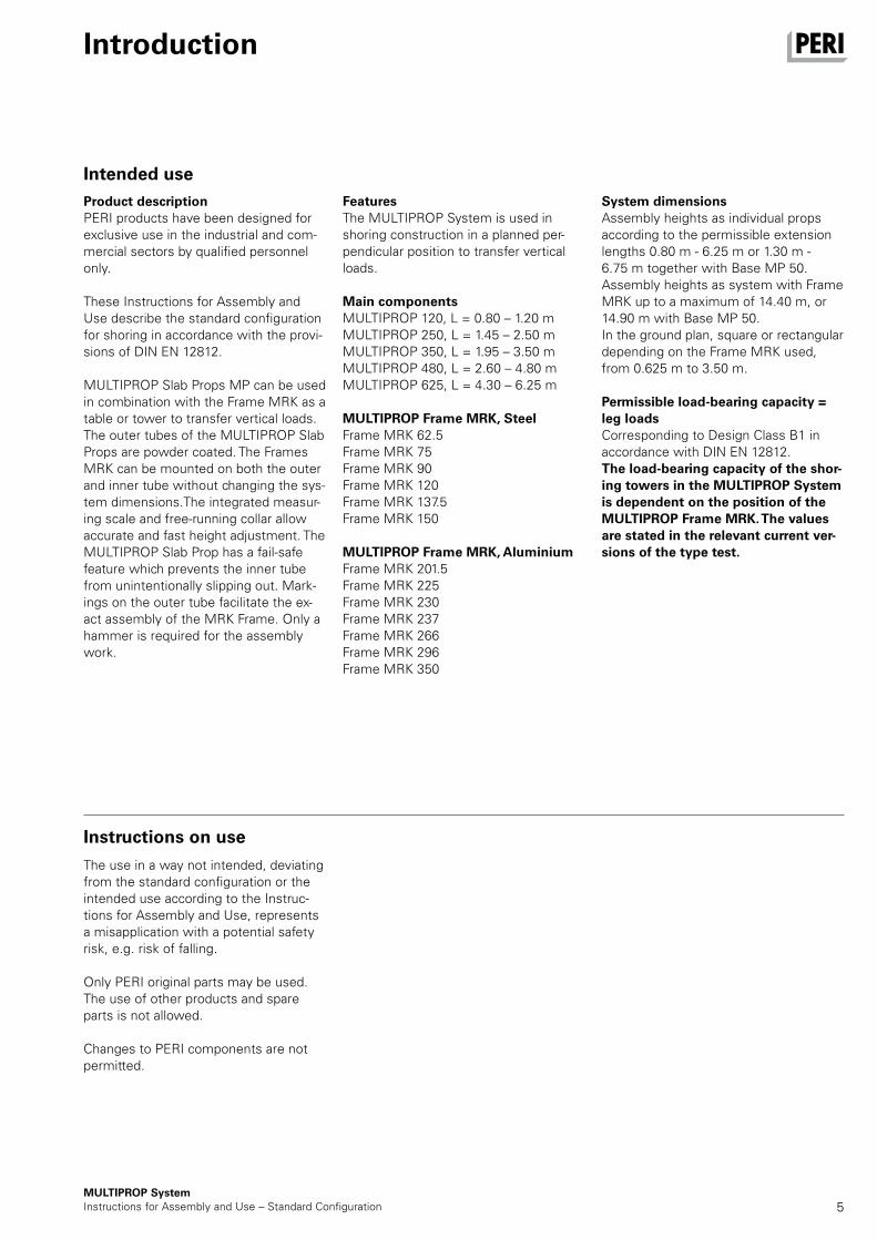
FeaturesThe MULTIPROP System is used in shoring construction in a planned per-pendicular position to transfer vertical loads.
Main componentsMULTIPROP 120, L = 0.80 – 1.20 mMULTIPROP 250, L = 1.45 – 2.50 mMULTIPROP 350, L = 1.95 – 3.50 mMULTIPROP 480, L = 2.60 – 4.80 mMULTIPROP 625, L = 4.30 – 6.25 m
MULTIPROP Frame MRK, SteelFrame MRK 62.5Frame MRK 75Frame MRK 90Frame MRK 120Frame MRK 137.5Frame MRK 150
MULTIPROP Frame MRK, AluminiumFrame MRK 201.5Frame MRK 225Frame MRK 230Frame MRK 237Frame MRK 266Frame MRK 296Frame MRK 350
System dimensionsAssembly heights as individual props according to the permissible extension lengths 0.80 m - 6.25 m or 1.30 m - 6.75 m together with Base MP 50.Assembly heights as system with Frame MRK up to a maximum of 14.40 m, or 14.90 m with Base MP 50.In the ground plan, square or rectangular depending on the Frame MRK used, from 0.625 m to 3.50 m.
Permissible load-bearing capacity = leg loadsCorresponding to Design Class B1 in accordance with DIN EN 12812.The load-bearing capacity of the shor-ing towers in the MULTIPROP System is dependent on the position of the MULTIPROP Frame MRK. The values are stated in the relevant current ver-sions of the type test.
Product descriptionPERI products have been designed for exclusive use in the industrial and com-mercial sectors by qualified personnel only.
These Instructions for Assembly and Use describe the standard configuration for shoring in accordance with the provi-sions of DIN EN 12812.
MULTIPROP Slab Props MP can be used in combination with the Frame MRK as a table or tower to transfer vertical loads. The outer tubes of the MULTIPROP Slab Props are powder coated. The Frames MRK can be mounted on both the outer and inner tube without changing the sys-tem dimensions.The integrated measur-ing scale and free-running collar allow accurate and fast height adjustment. The MULTIPROP Slab Prop has a fail-safe feature which prevents the inner tube from unintentionally slipping out. Mark-ings on the outer tube facilitate the ex-act assembly of the MRK Frame. Only a hammer is required for the assembly work.
Intended use
Instructions on use
6MULTIPROP System
Instructions for Assembly and Use – Standard Configuration
Introduction
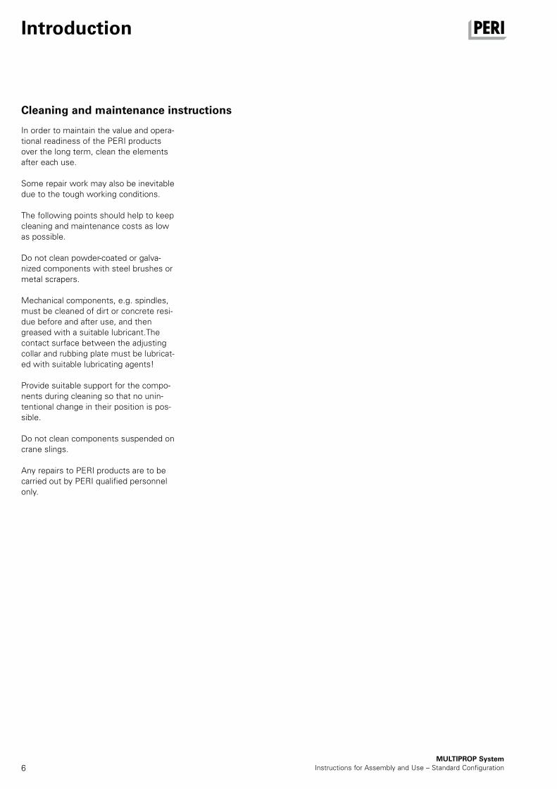
Cleaning and maintenance instructions
In order to maintain the value and opera-tional readiness of the PERI products over the long term, clean the elements after each use.
Some repair work may also be inevitable due to the tough working conditions.
The following points should help to keep cleaning and maintenance costs as low as possible.
Do not clean powder-coated or galva-nized components with steel brushes or metal scrapers.
Mechanical components, e.g. spindles, must be cleaned of dirt or concrete resi-due before and after use, and then greased with a suitable lubricant.The contact surface between the adjusting collar and rubbing plate must be lubricat-ed with suitable lubricating agents!
Provide suitable support for the compo-nents during cleaning so that no unin-tentional change in their position is pos-sible.
Do not clean components suspended on crane slings.
Any repairs to PERI products are to be carried out by PERI qualified personnel only.
7MULTIPROP SystemInstructions for Assembly and Use – Standard Configuration
Safety instructions
Cross-system
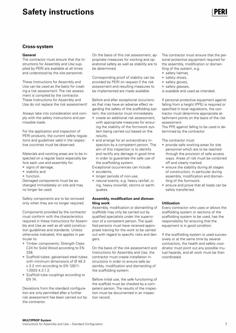
GeneralThe contractor must ensure that the In-structions for Assembly and Use sup-plied by PERI are available at all times and understood by the site personnel.
These Instructions for Assembly and Use can be used as the basis for creat-ing a risk assessment. The risk assess-ment is compiled by the contractor. These Instructions for Assembly and Use do not replace the risk assessment!
Always take into consideration and com-ply with the safety instructions and per-missible loads.
For the application and inspection of PERI products, the current safety regula-tions and guidelines valid in the respec-tive countries must be observed.
Materials and working areas are to be in-spected on a regular basis especially be-fore each use and assembly for:
signs of damage, stability and function.
Damaged components must be ex-changed immediately on site and may no longer be used.
Safety components are to be removed only when they are no longer required.
Components provided by the contractor must conform with the characteristics required in these Instructions for Assem-bly and Use as well as all valid construc-tion guidelines and standards. Unless otherwise indicated, this applies in par-ticular to:
Timber components: Strength Class C24 for Solid Wood according to EN 338.
Scaffold tubes: galvanised steel tubes with minimum dimensions of Ø 48.3 x 3.2 mm according to EN 12811-1:2003 4.2.1.2.
Scaffold tube couplings according to EN 74.
Deviations from the standard configura-tion are only permitted after a further risk assessment has been carried out by the contractor.
On the basis of this risk assessment, ap-propriate measures for working and op-erational safety as well as stability are to be determined.
Corresponding proof of stability can be provided by PERI on request if the risk assessment and resulting measures to be implemented are made available.
Before and after exceptional occurrenc-es that may have an adverse effect re-garding the safety of the scaffolding sys-tem, the contractor must immediately
create an additional risk assessment, with appropriate measures for ensur-ing the stability of the formwork sys-tem being carried out based on the results,
and arrange for an extraordinary in-spection by a competent person. The aim of this inspection is to identify and rectify any damage in good time in order to guarantee the safe use of the scaffolding system.
Exceptional occurrences can include: accidents, longer periods of non-use, natural events, e.g. heavy rainfall, ic-ing, heavy snowfall, storms or earth-quakes.
Assembly, modification and disman-tling workAssembly, modification or dismantling of scaffolds may only be carried out by qualified specialists under the supervi-sion of a competent person. The quali-fied persons must have received appro-priate training for the work to be carried out with regard to specific risks and dan-gers.
On the basis of the risk assessment and Instructions for Assembly and Use, the contractor must create installation in-structions in order to ensure safe as-sembly, modification and dismantling of the scaffolding system.
Before initial use, the safe functioning of the scaffold must be checked by a com-petent person. The results of the inspec-tion must be documented in an inspec-tion record.
The contractor must ensure that the per-sonal protective equipment required for the assembly, modification or disman-tling of the system, e.g.
safety helmet, safety shoes, safety gloves, safety glasses,
is available and used as intended.
If personal protective equipment against falling from a height (PPE) is required or specified in local regulations, the con-tractor must determine appropriate at-tachment points on the basis of the risk assessment.The PPE against falling to be used is de-termined by the contractor.
The contractor must provide safe working areas for site personnel which are to be reached through the provision of safe access ways. Areas of risk must be cordoned off and clearly marked.
ensure the stability during all stages of construction, in particular during assembly, modification and disman-tling of the formwork.
ensure and prove that all loads can be safely transferred.
UtilizationEvery contractor who uses or allows the scaffolding system or sections of the scaffolding system to be used, has the responsibility for ensuring that the equipment is in good condition.
If the scaffolding system is used succes-sively or at the same time by several contractors, the health and safety coor-dinator must point out any possible mu-tual hazards, and all work must be then coordinated.
8MULTIPROP System
Instructions for Assembly and Use – Standard Configuration
Safety instructions
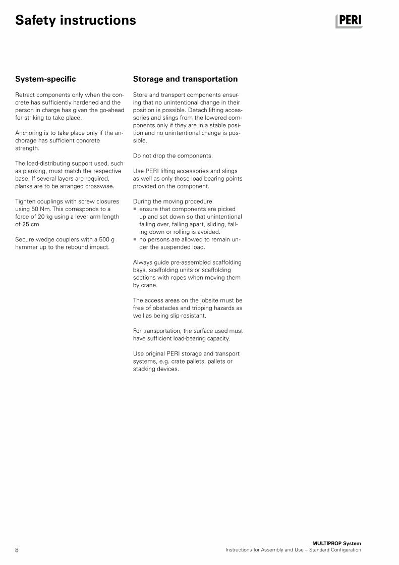
System-specific
Retract components only when the con-crete has sufficiently hardened and the person in charge has given the go-ahead for striking to take place.
Anchoring is to take place only if the an-chorage has sufficient concrete strength.
The load-distributing support used, such as planking, must match the respective base. If several layers are required, planks are to be arranged crosswise.
Tighten couplings with screw closures using 50 Nm. This corresponds to a force of 20 kg using a lever arm length of 25 cm.
Secure wedge couplers with a 500 g hammer up to the rebound impact.
Storage and transportation
Store and transport components ensur-ing that no unintentional change in their position is possible. Detach lifting acces-sories and slings from the lowered com-ponents only if they are in a stable posi-tion and no unintentional change is pos-sible.
Do not drop the components.
Use PERI lifting accessories and slings as well as only those load-bearing points provided on the component.
During the moving procedure ensure that components are picked up and set down so that unintentional falling over, falling apart, sliding, fall-ing down or rolling is avoided.
no persons are allowed to remain un-der the suspended load.
Always guide pre-assembled scaffolding bays, scaffolding units or scaffolding sections with ropes when moving them by crane.
The access areas on the jobsite must be free of obstacles and tripping hazards as well as being slip-resistant.
For transportation, the surface used must have sufficient load-bearing capacity.
Use original PERI storage and transport systems, e.g. crate pallets, pallets or stacking devices.
9MULTIPROP SystemInstructions for Assembly and Use – Standard Configuration
Foreseeable misapplications
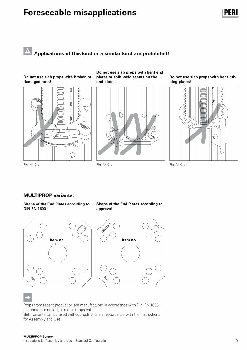
Do not use slab props with broken or damaged nuts!
Fig. A4.01a
Do not use slab props with bent end plates or split weld seams on the end plates!
Do not use slab props with bent rub-bing plates!
Fig. A4.01b Fig. A4.01c
MULTIPROP variants:
Applications of this kind or a similar kind are prohibited!
Props from recent production are manufactured in accordance with DIN EN 16031 and therefore no longer require approval.Both variants can be used without restrictions in accordance with the Instructions for Assembly and Use.
Shape of the End Plates according to DIN EN 16031
Shape of the End Plates according to approval
Item no. Item no.
10
1.4
1.4
1.7
1.7
1.2
1.6
1.3
1.3
1.2
MULTIPROP SystemInstructions for Assembly and Use – Standard Configuration
A1 MULTIPROP Individual Prop
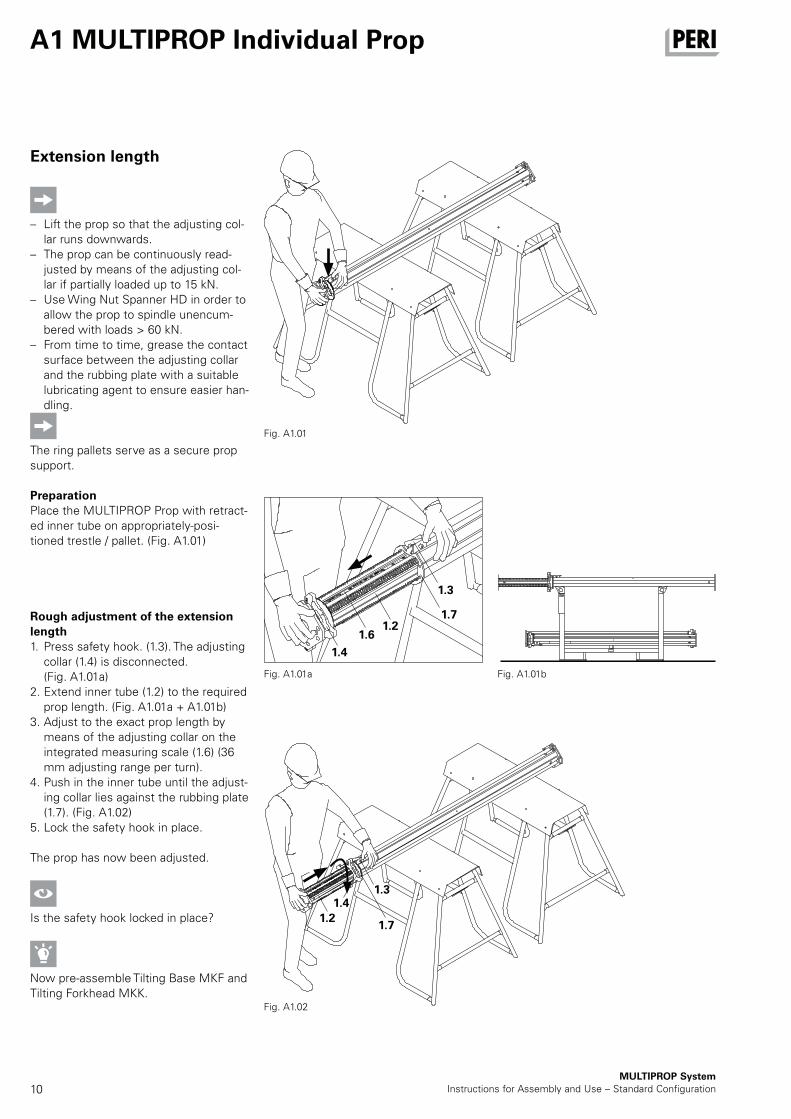
Extension length
– Lift the prop so that the adjusting col-lar runs downwards.
– The prop can be continuously read-justed by means of the adjusting col-lar if partially loaded up to 15 kN.
– Use Wing Nut Spanner HD in order to allow the prop to spindle unencum-bered with loads > 60 kN.
– From time to time, grease the contact surface between the adjusting collar and the rubbing plate with a suitable lubricating agent to ensure easier han-dling.
The ring pallets serve as a secure prop support.
PreparationPlace the MULTIPROP Prop with retract-ed inner tube on appropriately-posi-tioned trestle / pallet. (Fig. A1.01)
Rough adjustment of the extension length1. Press safety hook. (1.3). The adjusting
collar (1.4) is disconnected. (Fig. A1.01a)
2. Extend inner tube (1.2) to the required prop length. (Fig. A1.01a + A1.01b)
3. Adjust to the exact prop length by means of the adjusting collar on the integrated measuring scale (1.6) (36 mm adjusting range per turn).
4. Push in the inner tube until the adjust-ing collar lies against the rubbing plate (1.7). (Fig. A1.02)
5. Lock the safety hook in place.
The prop has now been adjusted.
Is the safety hook locked in place?
Now pre-assemble Tilting Base MKF and Tilting Forkhead MKK.
Fig. A1.01a
Fig. A1.01
Fig. A1.02
Fig. A1.01b
11
8.1
8.2
1.9
25 mm
1.8
1.9
7.3
7.1
7.2
MULTIPROP SystemInstructions for Assembly and Use – Standard Configuration
A2 MULTIPROP System
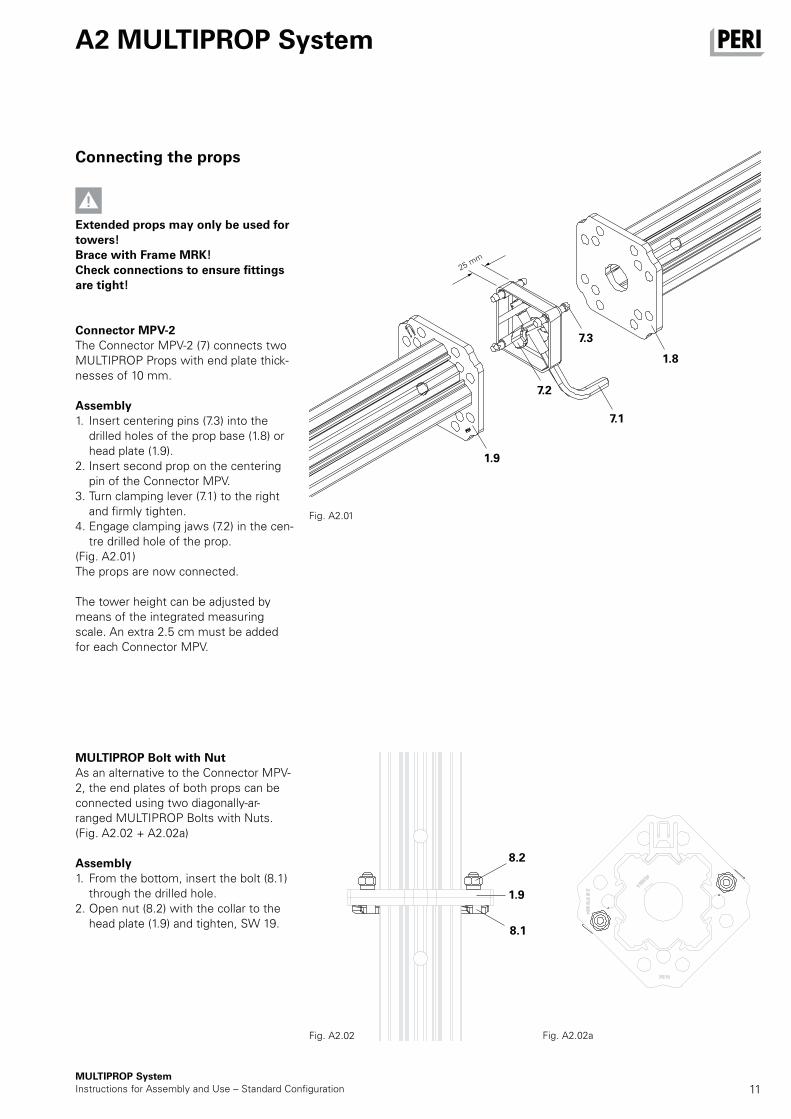
MULTIPROP Bolt with NutAs an alternative to the Connector MPV-2, the end plates of both props can be connected using two diagonally-ar-ranged MULTIPROP Bolts with Nuts. (Fig. A2.02 + A2.02a)
Assembly1. From the bottom, insert the bolt (8.1)
through the drilled hole. 2. Open nut (8.2) with the collar to the
head plate (1.9) and tighten, SW 19.
Connecting the props
Extended props may only be used for towers! Brace with Frame MRK! Check connections to ensure fittings are tight!
Connector MPV-2The Connector MPV-2 (7) connects two MULTIPROP Props with end plate thick-nesses of 10 mm.
Assembly1. Insert centering pins (7.3) into the
drilled holes of the prop base (1.8) or head plate (1.9).
2. Insert second prop on the centering pin of the Connector MPV.
3. Turn clamping lever (7.1) to the right and firmly tighten.
4. Engage clamping jaws (7.2) in the cen-tre drilled hole of the prop.
(Fig. A2.01)The props are now connected.
The tower height can be adjusted by means of the integrated measuring scale. An extra 2.5 cm must be added for each Connector MPV.
Fig. A2.01
Fig. A2.02 Fig. A2.02a
12
MULTIPROP SystemInstructions for Assembly and Use – Standard Configuration
A2 MULTIPROP System
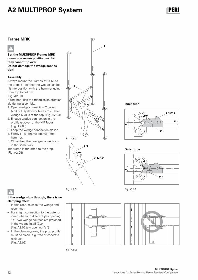
Frame MRK
Set the MULTIPROP Frames MRK down in a secure position so that they cannot tip over! Do not damage the wedge connec-tion!
AssemblyAlways mount the Frames MRK (2) to the props (1) so that the wedge can be hit into position with the hammer going from top to bottom. (Fig. A2.03)If required, use the tripod as an erection aid during assembly. 1. Open wedge connection C (silver)
(2.1) or D (yellow or black) (2.2). The wedge (2.3) is at the top. (Fig. A2.04)
2. Engage wedge connection in the profile grooves of the MP Tubes. (Fig. A2.05)
3. Keep the wedge connection closed. 4. Firmly strike the wedge with the
hammer. 5. Close the other wedge connections
in the same way. The frame is mounted to the prop. (Fig. A2.05)
If the wedge slips through, there is no clamping effect! – In this case, release the wedge and
reconnect. – For a tight connection to the outer or
inner tube with different jaw opening “a” two wedge courses are provided in the wedge itself (2.3). (Fig. A2.05 jaw opening “a”)
– In the clamping area, the prop profile must be clean, e.g. free of concrete residues.
(Fig. A2.06)
Fig. A2.05Fig. A2.04
Fig. A2.03
Fig. A2.06
Inner tube
Outer tube
1
2.1/2.2
2.3
ae
a
2.3
2.1/2.2
2.3
2
13
1.1095
0
95
0
40
0
40
0
MULTIPROP SystemInstructions for Assembly and Use – Standard Configuration
A2 MULTIPROP System
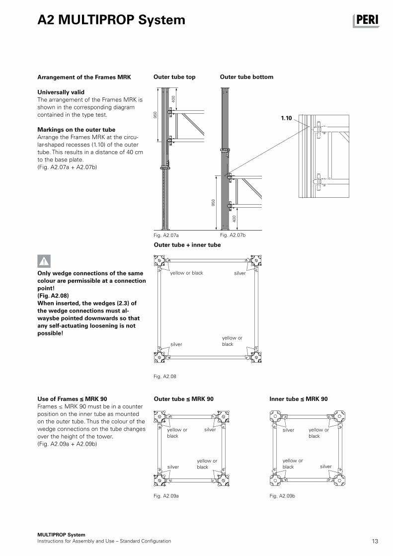
Only wedge connections of the same colour are permissible at a connection point! (Fig. A2.08)When inserted, the wedges (2.3) of the wedge connections must al-waysbe pointed downwards so that any self-actuating loosening is not possible!
Use of Frames ≤ MRK 90Frames ≤ MRK 90 must be in a counter position on the inner tube as mounted on the outer tube. Thus the colour of the wedge connections on the tube changes over the height of the tower. (Fig. A2.09a + A2.09b)
Arrangement of the Frames MRK
Universally validThe arrangement of the Frames MRK is shown in the corresponding diagram contained in the type test.
Markings on the outer tubeArrange the Frames MRK at the circu-lar-shaped recesses (1.10) of the outer tube. This results in a distance of 40 cm to the base plate. (Fig. A2.07a + A2.07b)
Fig. A2.09a
yellow or black
silveryellow or black
yellow or black silver
yellow or black
silver silver
silver silveryellow or black
yellow or black
Fig. A2.08
Outer tube + inner tube
Outer tube top Outer tube bottom
Outer tube ≤ MRK 90 Inner tube ≤ MRK 90
Fig. A2.09b
Fig. A2.07a Fig. A2.07b
14MULTIPROP System
Instructions for Assembly and Use – Standard Configuration
A2 MULTIPROP System
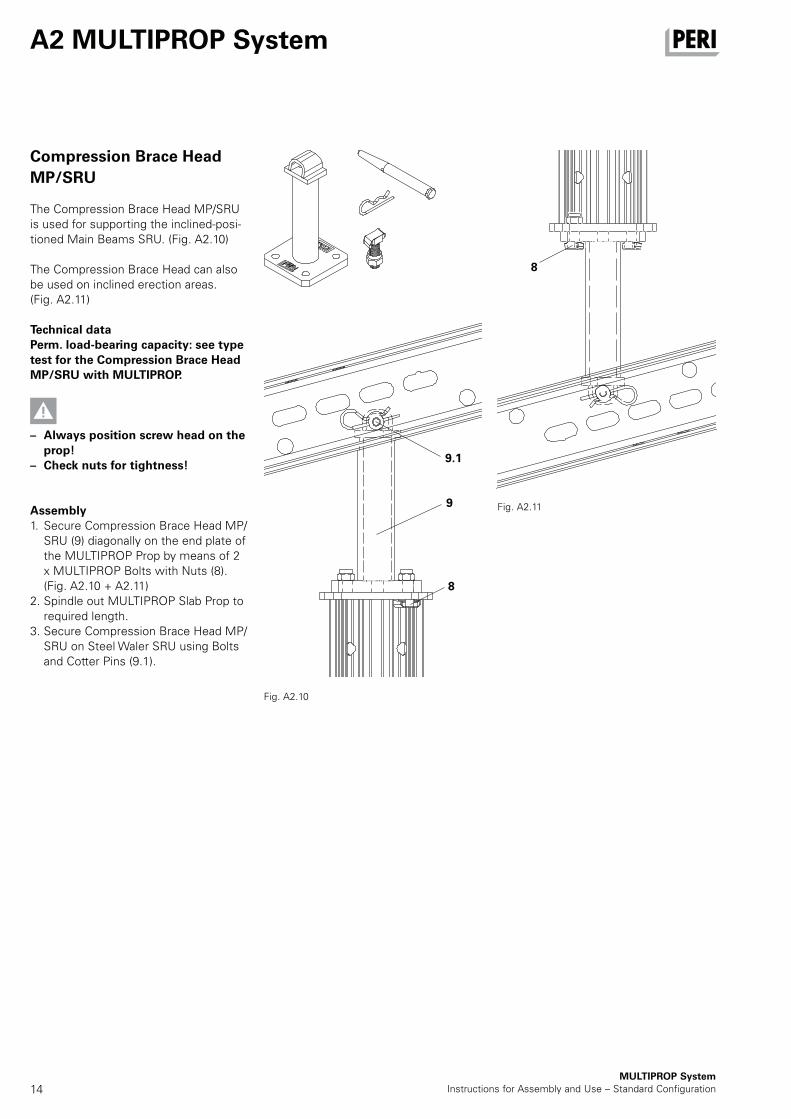
Compression Brace Head
MP/SRU
The Compression Brace Head MP/SRU is used for supporting the inclined-posi-tioned Main Beams SRU. (Fig. A2.10)
The Compression Brace Head can also be used on inclined erection areas. (Fig. A2.11)
Technical dataPerm. load-bearing capacity: see type test for the Compression Brace Head MP/SRU with MULTIPROP.
– Always position screw head on the prop!
– Check nuts for tightness!
Assembly1. Secure Compression Brace Head MP/
SRU (9) diagonally on the end plate of the MULTIPROP Prop by means of 2 x MULTIPROP Bolts with Nuts (8). (Fig. A2.10 + A2.11)
2. Spindle out MULTIPROP Slab Prop to required length.
3. Secure Compression Brace Head MP/SRU on Steel Waler SRU using Bolts and Cotter Pins (9.1).
Fig. A2.10
9
8
8
9.1
Fig. A2.11
15MULTIPROP SystemInstructions for Assembly and Use – Standard Configuration
A2 MULTIPROP System
Tilting Base MKF
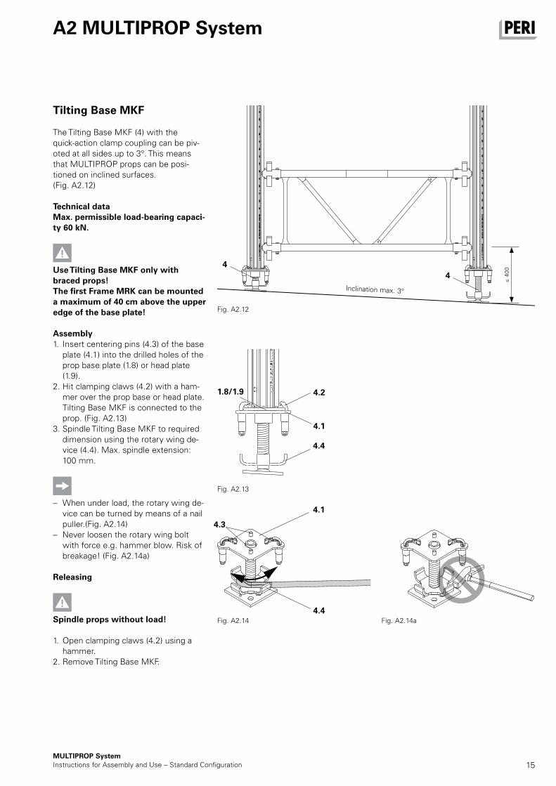
The Tilting Base MKF (4) with the quick-action clamp coupling can be piv-oted at all sides up to 3°. This means that MULTIPROP props can be posi-tioned on inclined surfaces. (Fig. A2.12)
Technical dataMax. permissible load-bearing capaci-ty 60 kN.
Use Tilting Base MKF only with braced props! The first Frame MRK can be mounted a maximum of 40 cm above the upper edge of the base plate!
Assembly1. Insert centering pins (4.3) of the base
plate (4.1) into the drilled holes of the prop base plate (1.8) or head plate (1.9).
2. Hit clamping claws (4.2) with a ham-mer over the prop base or head plate. Tilting Base MKF is connected to the prop. (Fig. A2.13)
3. Spindle Tilting Base MKF to required dimension using the rotary wing de-vice (4.4). Max. spindle extension: 100 mm.
– When under load, the rotary wing de-vice can be turned by means of a nail puller.(Fig. A2.14)
– Never loosen the rotary wing bolt with force e.g. hammer blow. Risk of breakage! (Fig. A2.14a)
Releasing
Spindle props without load!
1. Open clamping claws (4.2) using a hammer.
2. Remove Tilting Base MKF.
Fig. A2.12
Inclination max. 3°
≤ 4
00
Fig. A2.13
Fig. A2.14 Fig. A2.14a
4
4
1.8/1.9
4.4
4.4
4.1
4.3
4.1
4.2
16MULTIPROP System
Instructions for Assembly and Use – Standard Configuration
A2 MULTIPROP System
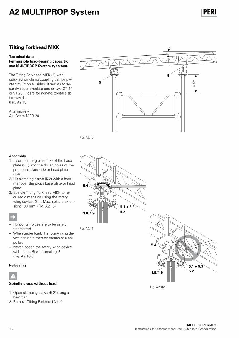
Tilting Forkhead MKK
Technical dataPermissible load-bearing capacity: see MULTIPROP System type test.
The Tilting Forkhead MKK (5) with quick-action clamp coupling can be piv-oted by 3° on all sides. It serves to se-curely accommodate one or two GT 24 or VT 20 Firders for non-horizontal slab formwork. (Fig. A2.15)
AlternativelyAlu Beam MPB 24
Assembly1. Insert centring pins (5.3) of the base
plate (5.1) into the drilled holes of the prop base plate (1.8) or head plate (1.9).
2. Hit clamping claws (5.2) with a ham-mer over the props base plate or head plate.
3. Spindle Tilting Forkhead MKK to re-quired dimension using the rotary wing device (5.4). Max. spindle exten-sion: 100 mm. (Fig. A2.16)
– Horizontal forces are to be safely transferred.
– When under load, the rotary wing de-vice can be turned by means of a nail puller.
– Never loosen the rotary wing device with force. Risk of breakage! (Fig. A2.16a)
Releasing
Spindle props without load!
1. Open clamping claws (5.2) using a hammer.
2. Remove Tilting Forkhead MKK.
Fig. A2.16
Fig. A2.16a
Fig. A2.15
5
5
5.4
5.4
5.2
5.2
5.1 + 5.3
5.1 + 5.3
1.8/1.9
1.8/1.9
≤ 4
00
3°
17MULTIPROP SystemInstructions for Assembly and Use – Standard Configuration
A2 MULTIPROP System
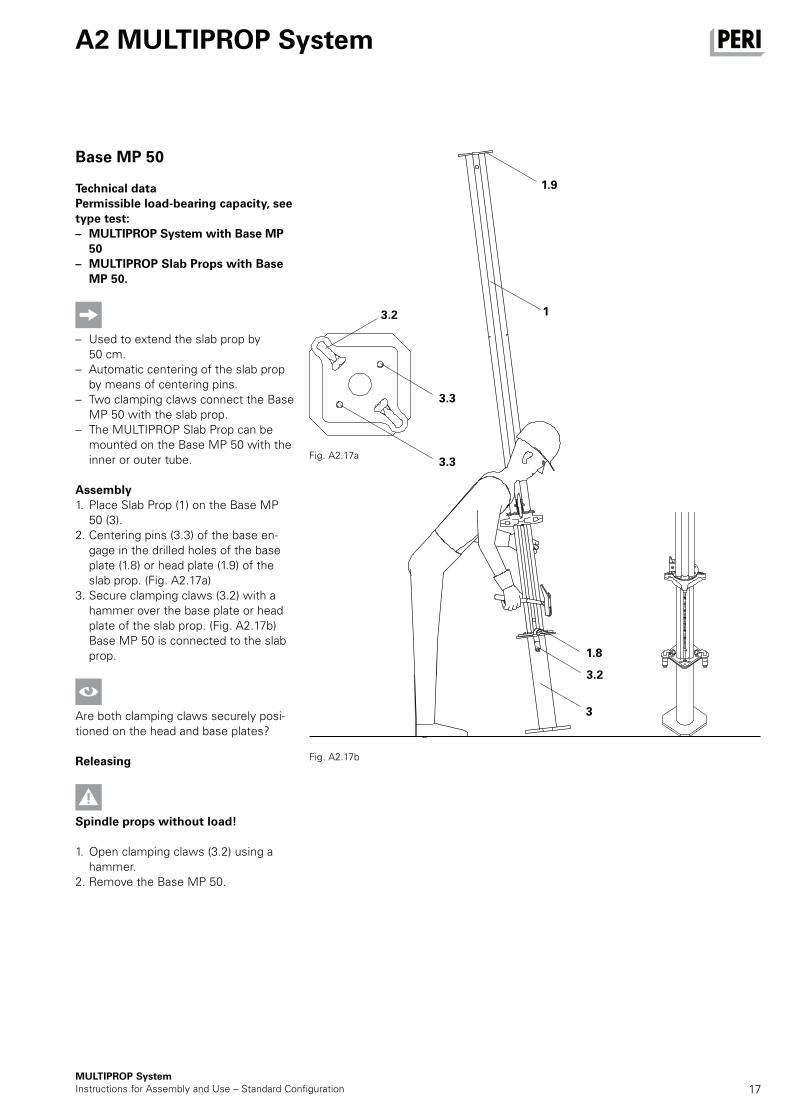
Base MP 50
Technical dataPermissible load-bearing capacity, see type test: – MULTIPROP System with Base MP 50
– MULTIPROP Slab Props with Base MP 50.
– Used to extend the slab prop by 50 cm.
– Automatic centering of the slab prop by means of centering pins.
– Two clamping claws connect the Base MP 50 with the slab prop.
– The MULTIPROP Slab Prop can be mounted on the Base MP 50 with the inner or outer tube.
Assembly1. Place Slab Prop (1) on the Base MP
50 (3). 2. Centering pins (3.3) of the base en-
gage in the drilled holes of the base plate (1.8) or head plate (1.9) of the slab prop. (Fig. A2.17a)
3. Secure clamping claws (3.2) with a hammer over the base plate or head plate of the slab prop. (Fig. A2.17b) Base MP 50 is connected to the slab prop.
Are both clamping claws securely posi-tioned on the head and base plates?
Releasing
Spindle props without load!
1. Open clamping claws (3.2) using a hammer.
2. Remove the Base MP 50.
Fig. A2.17a
Fig. A2.17b
3.2
1.9
1
3.3
3.3
3
3.2
1.8
18MULTIPROP System
Instructions for Assembly and Use – Standard Configuration
A3 Horizontal assembly
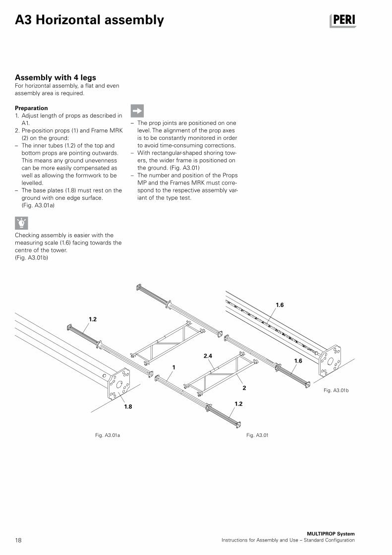
Assembly with 4 legsFor horizontal assembly, a flat and even assembly area is required.
Preparation1. Adjust length of props as described in
A1. 2. Pre-position props (1) and Frame MRK
(2) on the ground: – The inner tubes (1.2) of the top and
bottom props are pointing outwards. This means any ground unevenness can be more easily compensated as well as allowing the formwork to be levelled.
– The base plates (1.8) must rest on the ground with one edge surface. (Fig. A3.01a)
Checking assembly is easier with the measuring scale (1.6) facing towards the centre of the tower.(Fig. A3.01b)
– The prop joints are positioned on one level. The alignment of the prop axes is to be constantly monitored in order to avoid time-consuming corrections.
– With rectangular-shaped shoring tow-ers, the wider frame is positioned on the ground. (Fig. A3.01)
– The number and position of the Props MP and the Frames MRK must corre-spond to the respective assembly var-iant of the type test.
Fig. A3.01a
Fig. A3.01b
Fig. A3.01
1.2
1.21.8
1.6
1.62.4
1
2
19MULTIPROP SystemInstructions for Assembly and Use – Standard Configuration
A3 Horizontal assembly
Assembly with 4 legs
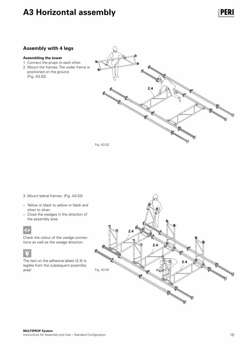
Assembling the tower1. Connect the props to each other. 2. Mount the frames. The wider frame is
positioned on the ground. (Fig. A3.02)
3. Mount lateral frames. (Fig. A3.03)
– Yellow or black to yellow or black and silver to silver.
– Close the wedges in the direction of the assembly area.
Check the colour of the wedge connec-tions as well as the wedge direction.
The text on the adhesive labels (2.4) is legible from the subsequent assembly area!
Fig. A3.02
Fig. A3.03
2.4
2.4
2.4
2.4
20MULTIPROP System
Instructions for Assembly and Use – Standard Configuration
A3 Horizontal assembly
Assembly with 4 legs
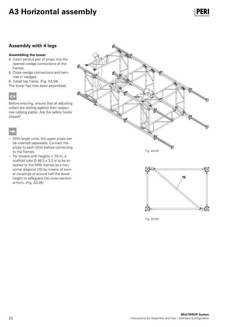
Assembling the tower4. Insert second pair of props into the
opened wedge connections of the frames.
5. Close wedge connections and ham-mer in wedges.
6. Install top frame. (Fig. A3.04)The tower has now been assembled.
Before erecting, ensure that all adjusting collars are resting against their respec-tive rubbing plates. Are the safety hooks closed?
– With larger units, the upper props can be inserted separately. Connect the props to each other before connecting to the frames.
– For towers with heights > 7.0 m, a scaffold tube Ø 48.3 x 3.2 is to be at-tached to the MRK frames as a hori-zontal diagonal (10) by means of swiv-el couplings at around half the tower height to safeguard the cross-section-al form. (Fig. A3.05)
Fig. A3.05
Fig. A3.04
10
21MULTIPROP SystemInstructions for Assembly and Use – Standard Configuration
A3 Horizontal assembly
Assembly with multiple
number of legs - example
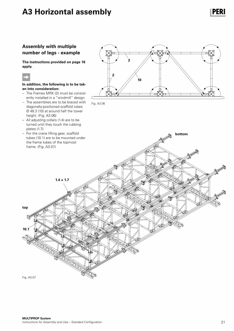
The instructions provided on page 16 apply.
In addition, the following is to be tak-en into consideration: – The Frames MRK (2) must be consist-
ently installed in a “windmill” design. – The assemblies are to be braced with
diagonally-positioned scaffold tubes Ø 48.3 (10) at around half the tower height. (Fig. A3.06)
– All adjusting collars (1.4) are to be turned until they touch the rubbing plates (1.7).
– For the crane lifting gear, scaffold tubes (10.1) are to be mounted under the frame tubes of the topmost frame. (Fig. A3.07)
Fig. A3.06
Fig. A3.07
1.4 + 1.7
bottom
top
10.1
2
2
10
22MULTIPROP System
Instructions for Assembly and Use – Standard Configuration
A3 Horizontal assembly
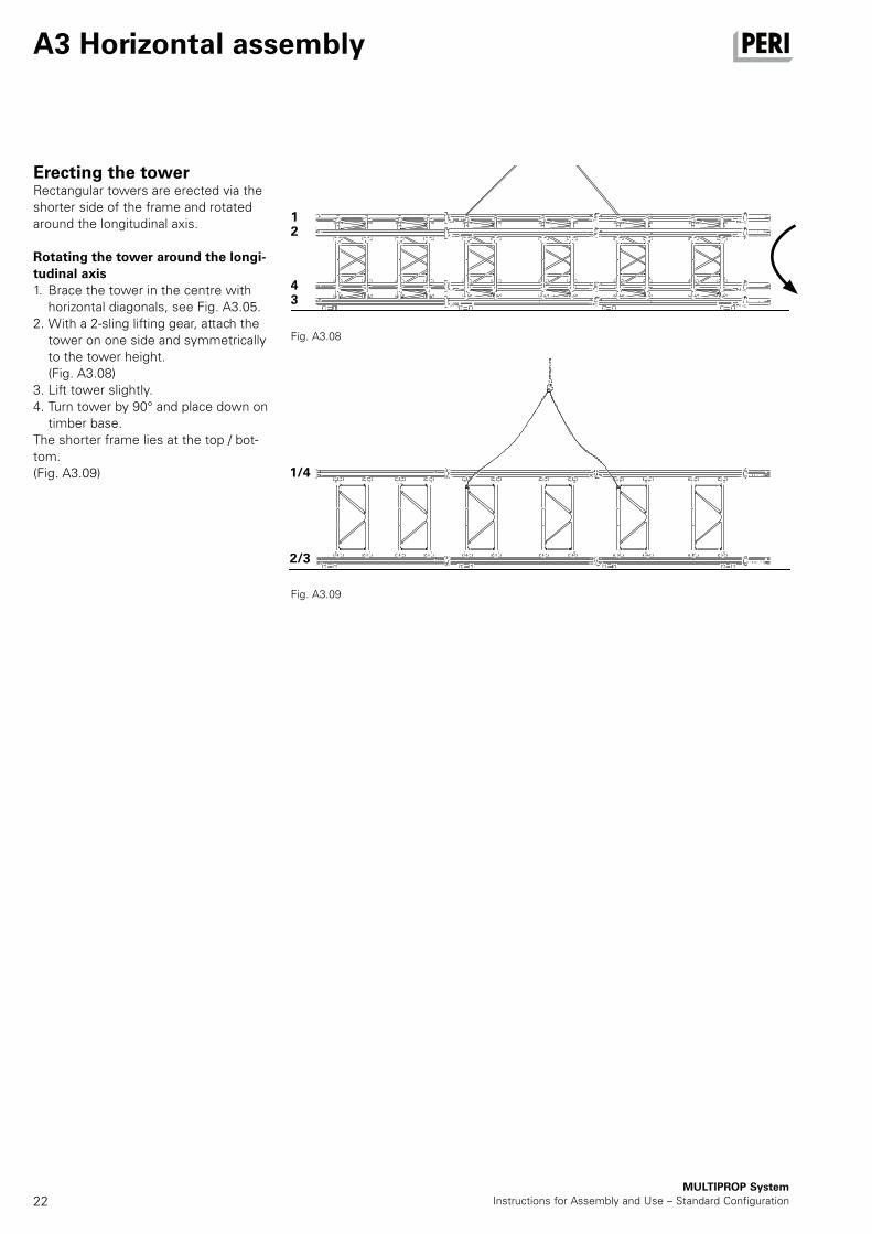
Erecting the towerRectangular towers are erected via the shorter side of the frame and rotated around the longitudinal axis.
Rotating the tower around the longi-tudinal axis1. Brace the tower in the centre with
horizontal diagonals, see Fig. A3.05. 2. With a 2-sling lifting gear, attach the
tower on one side and symmetrically to the tower height.
(Fig. A3.08)3. Lift tower slightly. 4. Turn tower by 90° and place down on
timber base. The shorter frame lies at the top / bot-tom.(Fig. A3.09)
Fig. A3.08
Fig. A3.09
1
1/4
4
2
3
2/3
23MULTIPROP SystemInstructions for Assembly and Use – Standard Configuration
A3 Horizontal assembly
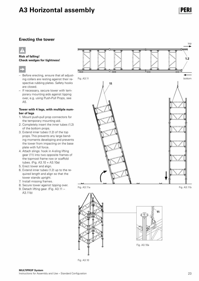
Erecting the tower
Risk of falling!Check wedges for tightness!
– Before erecting, ensure that all adjust-ing collars are resting against their re-spective rubbing plates. Safety hooks are closed.
– If necessary, secure tower with tem-porary mounting aids against tipping over, e.g. using Push-Pull Props, see A5.
Tower with 4 legs, with multiple num-ber of legs1. Mount push-pull prop connectors for
the temporary mounting aid.2. Completely insert the inner tubes (1.2)
of the bottom props. 3. Extend inner tubes (1.2) of the top
props. This prevents any large bend-ing moments developing and prevents the tower from impacting on the base plate with full force.
4. Attach slings: hook in 4-sling lifting gear (11) into two opposite frames of the topmost frame row or scaffold tubes. (Fig. A3.10 + A3.10a)
5. Erect tower and align. 6. Extend inner tubes (1.2) up to the re-
quired length and align so that the tower stands upright.
7. Install missing frames. 8. Secure tower against tipping over. 9. Detach lifting gear. (Fig. A3.11 –
A3.11b)
Fig. A3.10
Fig. A3.10a
Fig. A3.11
Fig. A3.11a Fig. A3.11b
1.2
11
11
bottom
top
24
1.2
2 2.32.4
12
11.61.6
MULTIPROP SystemInstructions for Assembly and Use – Standard Configuration
A4 Vertical assembly
First level
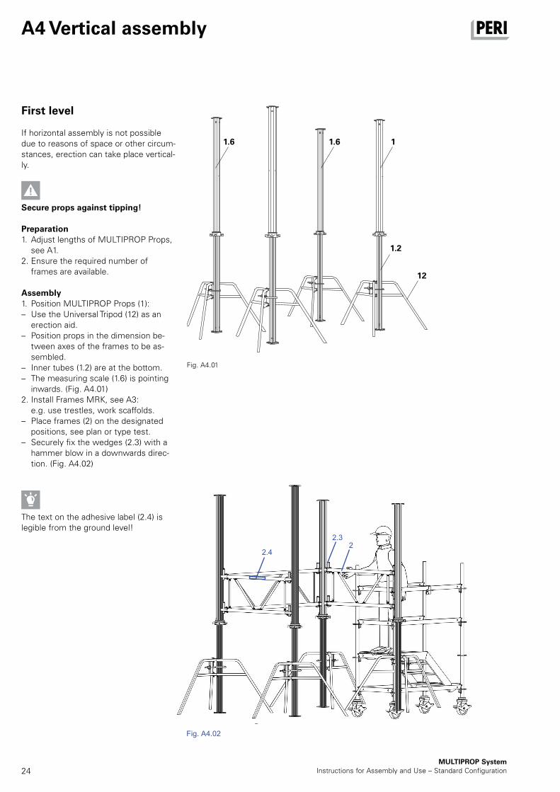
If horizontal assembly is not possible due to reasons of space or other circum-stances, erection can take place vertical-ly.
Secure props against tipping!
Preparation1. Adjust lengths of MULTIPROP Props,
see A1. 2. Ensure the required number of
frames are available.
Assembly1. Position MULTIPROP Props (1): – Use the Universal Tripod (12) as an
erection aid. – Position props in the dimension be-
tween axes of the frames to be as-sembled.
– Inner tubes (1.2) are at the bottom. – The measuring scale (1.6) is pointing
inwards. (Fig. A4.01)2. Install Frames MRK, see A3: e.g. use trestles, work scaffolds. – Place frames (2) on the designated
positions, see plan or type test. – Securely fix the wedges (2.3) with a
hammer blow in a downwards direc-tion. (Fig. A4.02)
–
The text on the adhesive label (2.4) is legible from the ground level!
Fig. A4.01
Fig. A4.02
22.3
2.4
Fig. A4.02
25
16
e
MULTIPROP SystemInstructions for Assembly and Use – Standard Configuration
A4 Vertical assembly
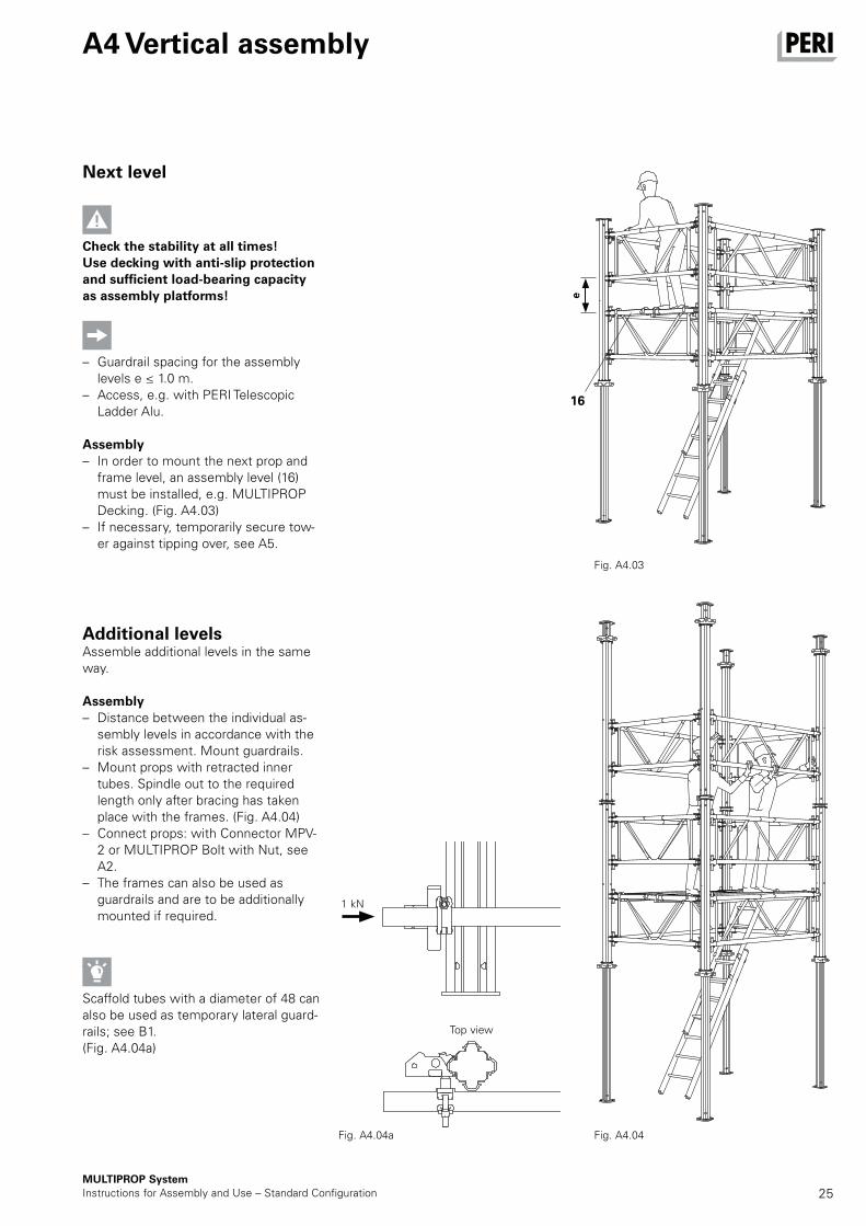
Next level
Check the stability at all times! Use decking with anti-slip protection and sufficient load-bearing capacity as assembly platforms!
– Guardrail spacing for the assembly levels e ≤ 1.0 m.
– Access, e.g. with PERI Telescopic Ladder Alu.
Assembly – In order to mount the next prop and
frame level, an assembly level (16) must be installed, e.g. MULTIPROP Decking. (Fig. A4.03)
– If necessary, temporarily secure tow-er against tipping over, see A5.
Additional levelsAssemble additional levels in the same way.
Assembly – Distance between the individual as-
sembly levels in accordance with the risk assessment. Mount guardrails.
– Mount props with retracted inner tubes. Spindle out to the required length only after bracing has taken place with the frames. (Fig. A4.04)
– Connect props: with Connector MPV-2 or MULTIPROP Bolt with Nut, see A2.
– The frames can also be used as guardrails and are to be additionally mounted if required.
–
Scaffold tubes with a diameter of 48 can also be used as temporary lateral guard-rails; see B1.(Fig. A4.04a)
Fig. A4.03
Fig. A4.04Fig. A4.04a
Top view
1 kN
26
13
13
138 88
7.1
1414
14
14
MULTIPROP SystemInstructions for Assembly and Use – Standard Configuration
A5 Bracing MULTIPROP Towers
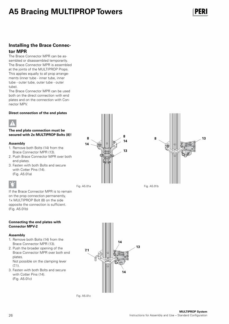
Installing the Brace Connec-
tor MPRThe Brace Connector MPR can be as-sembled or disassembled temporarily.The Brace Connector MPR is assembled at the joints of the MULTIPROP Props. This applies equally to all prop arrange-ments (inner tube - inner tube, inner tube - outer tube, outer tube - outer tube).The Brace Connector MPR can be used both on the direct connection with end plates and on the connection with Con-nector MPV.
Direct connection of the end plates
The end plate connection must be secured with 2x MULTIPROP Bolts (8)!
Assembly1. Remove both Bolts (14) from the
Brace Connector MPR (13).2. Push Brace Connector MPR over both
end plates.3. Fasten with both Bolts and secure
with Cotter Pins (14). (Fig. A5.01a)
If the Brace Connector MPR is to remain on the prop connection permanently, 1x MULTIPROP Bolt (8) on the side opposite the connection is sufficient. (Fig. A5.01b)
Connecting the end plates with Connector MPV-2
Assembly1. Remove both Bolts (14) from the
Brace Connector MPR (13).2. Push the broader opening of the
Brace Connector MPR over both end plates.
Not possible on the clamping lever (7.1).
3. Fasten with both Bolts and secure with Cotter Pins (14).
(Fig. A5.01c)
Fig. A5.01a Fig. A5.01b
Fig. A5.01c
27MULTIPROP SystemInstructions for Assembly and Use – Standard Configuration
A5 Bracing MULTIPROP Towers
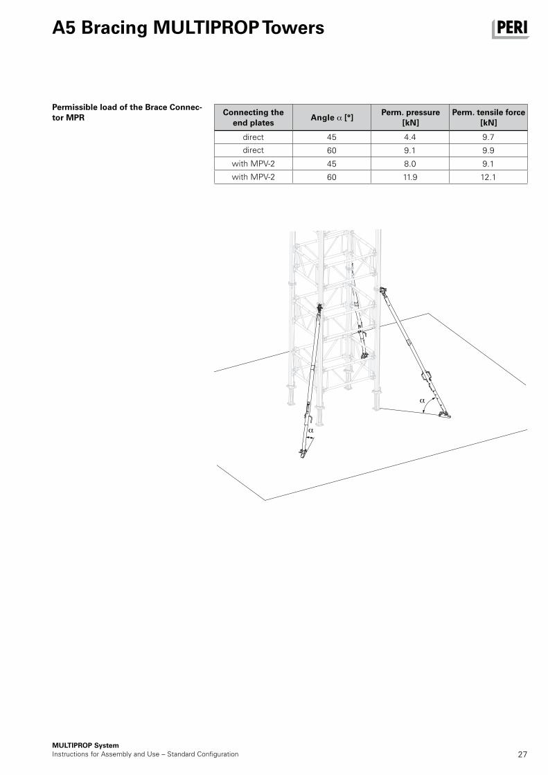
45 4.4 9.7
60 9.1 9.9
45 8.0 9.1
60 11.9 12.1
Permissible load of the Brace Connec-tor MPR
direct
Angle [°]Connecting the
end platesPerm. pressure
[kN]Perm. tensile force
[kN]
with MPV-2
with MPV-2
direct
28
13
MULTIPROP SystemInstructions for Assembly and Use – Standard Configuration
A5 Bracing MULTIPROP Towers
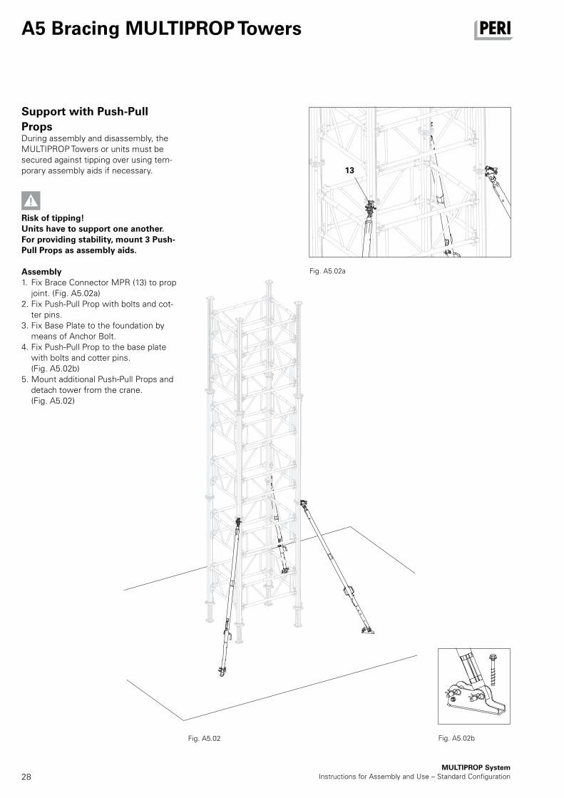
Support with Push-Pull
PropsDuring assembly and disassembly, the MULTIPROP Towers or units must be secured against tipping over using tem-porary assembly aids if necessary.
Risk of tipping!Units have to support one another. For providing stability, mount 3 Push-Pull Props as assembly aids.
Assembly1. Fix Brace Connector MPR (13) to prop
joint. (Fig. A5.02a)2. Fix Push-Pull Prop with bolts and cot-
ter pins.3. Fix Base Plate to the foundation by
means of Anchor Bolt.4. Fix Push-Pull Prop to the base plate
with bolts and cotter pins. (Fig. A5.02b)
5. Mount additional Push-Pull Props and detach tower from the crane.
(Fig. A5.02)
Fig. A5.02a
Fig. A5.02 Fig. A5.02b
29
13
MULTIPROP SystemInstructions for Assembly and Use – Standard Configuration
A5 Bracing MULTIPROP Towers
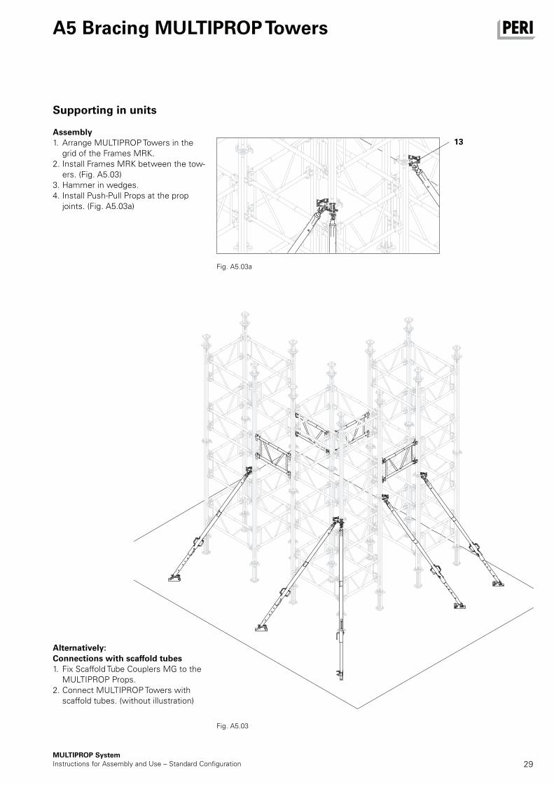
Supporting in units
Assembly1. Arrange MULTIPROP Towers in the
grid of the Frames MRK.2. Install Frames MRK between the tow-
ers. (Fig. A5.03)3. Hammer in wedges.4. Install Push-Pull Props at the prop
joints. (Fig. A5.03a)
Alternatively:Connections with scaffold tubes1. Fix Scaffold Tube Couplers MG to the
MULTIPROP Props.2. Connect MULTIPROP Towers with
scaffold tubes. (without illustration)
Fig. A5.03a
Fig. A5.03
30
1.8/1.9
6,5
8
6.1
U10
0-U
140
6.4
6.2
MULTIPROP SystemInstructions for Assembly and Use – Standard Configuration
A6 Accessories
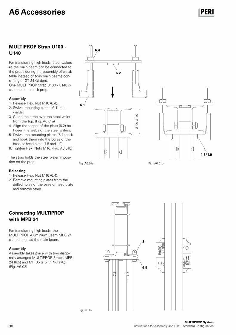
MULTIPROP Strap U100 -
U140
For transferring high loads, steel walers as the main beam can be connected to the props during the assembly of a slab table instead of twin main beams con-sisting of GT 24 Girders. One MULTIPROP Strap U100 - U140 is assembled to each prop.
Assembly1. Release Hex. Nut M16 (6.4). 2. Swivel mounting plates (6.1) out-
wards.3. Guide the strap over the steel waler
from the top. (Fig. A6.01a)4. Align the tappet of the plate (6.2) be-
tween the webs of the steel walers.5. Swivel the mounting plates (6.1) back
and hook them into the bores of the base or head plate (1.8 and 1.9).
6. Tighten Hex. Nuts M16. (Fig. A6.01b)
The strap holds the steel waler in posi-tion on the prop.
Releasing1. Release Hex. Nut M16 (6.4). 2. Remove mounting plates from the
drilled holes of the base or head plate and remove strap.
Connecting MULTIPROP
with MPB 24
For transferring high loads, the MULTIPROP Aluminium Beam MPB 24 can be used as the main beam.
AssemblyAssembly takes place with two diago-nally-arranged MULTIPROP Straps MPB 24 (6.5) and MP Bolts with Nuts (8).(Fig. A6.02)
Fig. A6.02
Fig. A6.01a Fig. A6.01b
31
9
9
17
17
40
0
MULTIPROP SystemInstructions for Assembly and Use – Standard Configuration
A6 Accessories
Compression Brace Head
MP/SRU with Connector
MP/SRU
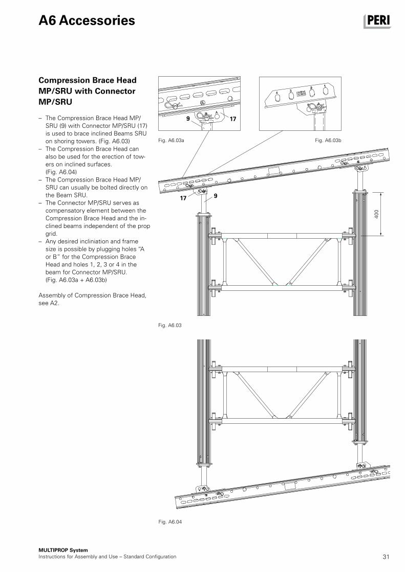
– The Compression Brace Head MP/SRU (9) with Connector MP/SRU (17) is used to brace inclined Beams SRU on shoring towers. (Fig. A6.03)
– The Compression Brace Head can also be used for the erection of tow-ers on inclined surfaces.
(Fig. A6.04) – The Compression Brace Head MP/
SRU can usually be bolted directly on the Beam SRU.
– The Connector MP/SRU serves as compensatory element between the Compression Brace Head and the in-clined beams independent of the prop grid.
– Any desired incliniation and frame size is possible by plugging holes “A or B” for the Compression Brace Head and holes 1, 2, 3 or 4 in the beam for Connector MP/SRU. (Fig. A6.03a + A6.03b)
Assembly of Compression Brace Head, see A2.
Fig. A6.03
Fig. A6.03a Fig. A6.03b
Fig. A6.04
32MULTIPROP System
Instructions for Assembly and Use – Standard Configuration
A7 Dismantling
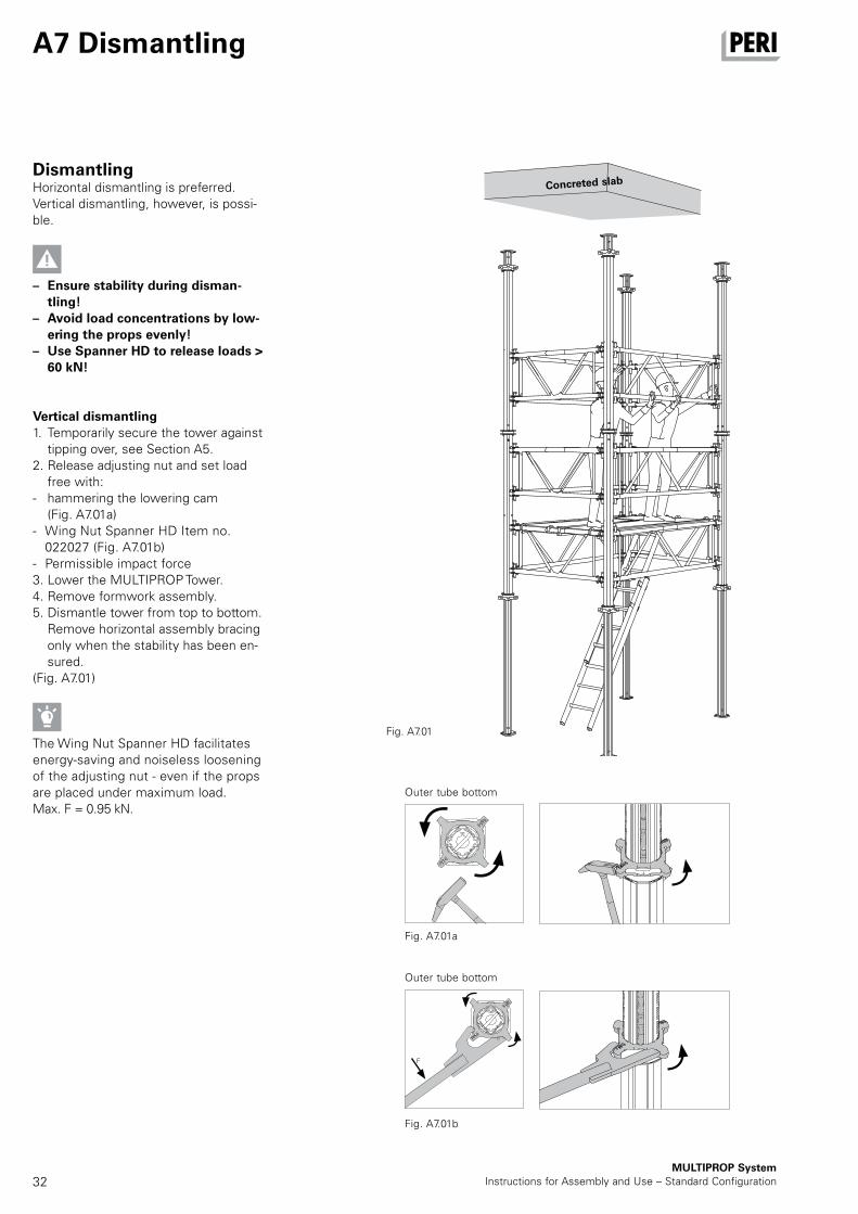
DismantlingHorizontal dismantling is preferred. Vertical dismantling, however, is possi-ble.
– Ensure stability during disman-tling!
– Avoid load concentrations by low-ering the props evenly!
– Use Spanner HD to release loads > 60 kN!
Vertical dismantling1. Temporarily secure the tower against
tipping over, see Section A5.2. Release adjusting nut and set load
free with:- hammering the lowering cam
(Fig. A7.01a)- Wing Nut Spanner HD Item no.
022027 (Fig. A7.01b)- Permissible impact force3. Lower the MULTIPROP Tower. 4. Remove formwork assembly. 5. Dismantle tower from top to bottom.
Remove horizontal assembly bracing only when the stability has been en-sured.
(Fig. A7.01)
The Wing Nut Spanner HD facilitates energy-saving and noiseless loosening of the adjusting nut - even if the props are placed under maximum load.Max. F = 0.95 kN.
Fig. A7.01
Concreted slab
Fig. A7.01a
Fig. A7.01b
Outer tube bottom
Outer tube bottom
F
33MULTIPROP SystemInstructions for Assembly and Use – Standard Configuration
Fig. A7.02
A7 Dismantling
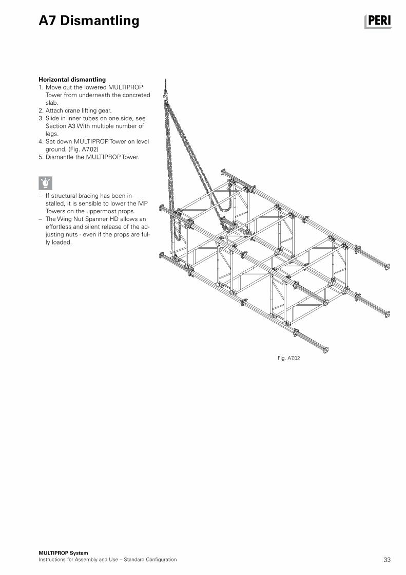
Horizontal dismantling1. Move out the lowered MULTIPROP
Tower from underneath the concreted slab.
2. Attach crane lifting gear. 3. Slide in inner tubes on one side, see
Section A3 With multiple number of legs.
4. Set down MULTIPROP Tower on level ground. (Fig. A7.02)
5. Dismantle the MULTIPROP Tower.
– If structural bracing has been in-stalled, it is sensible to lower the MP Towers on the uppermost props.
– The Wing Nut Spanner HD allows an effortless and silent release of the ad-justing nuts - even if the props are ful-ly loaded.

34
1.2
1.3
MULTIPROP SystemInstructions for Assembly and Use – Standard Configuration
– Instructions for Use for PERI Pallets and Stacking Devices must be fol-lowed at all times!
– Transportation units must be cor-rectly stacked and secured!
The safety hook (1.3) prevents the inner tube (1.2) from slipping out and must be engaged.
TransportationPERI Pallets and Stacking Devices are suitable for lifting by crane or forklift. They can also be moved with the PERI Pallet Lifting Trolley. All Pallets and Stacking Devices can be lifted using both the longitudinal and front sides.
The following are just some examples.MULTIPROP Slab Props with timber and steel strapping. (Fig. A8.02) MULTIPROP Frame MRK with steel strapping. (Fig. A8.04)
Fig. A8.01
Fig. A8.03 Fig. A8.04
Fig. A8.02
A8 Storage and transportation
35MULTIPROP SystemInstructions for Assembly and Use – Standard Configuration
B1 Structural scaffold tube bracings
Scaffold Tube Coupling MG
Check stability against tipping over!
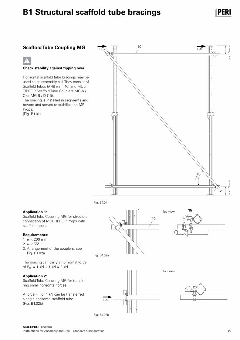
Horizontal scaffold tube bracings may be used as an assembly aid. They consist of Scaffold Tubes Ø 48 mm (10) and MUL-TIPROP Scaffold Tube Couplers MG-A / C or MG-B / D (15). The bracing is installed in segments and towers and serves to stabilize the MP Props. (Fig. B1.01)
Application 1:Scaffold Tube Coupling MG for structural connection of MULTIPROP Props with scaffold tubes.
Requirements:1. < 200 mm2. < 55°3. Arrangement of the couplers, see
Fig. B1.02a.
The bracing can carry a horizontal force of FH = 1 kN + 1 kN = 2 kN.
Application 2:Scaffold Tube Coupling MG for transfer-ring small horizontal forces.
A force FH of 1 kN can be transferred along a horizontal scaffold tube. (Fig. B1.02b)
Top view
Fig. B1.02b
Fig. B1.02a
Fig. B1.01
Top view
10
10
15
< 5
5˚
< 2
00
mm
< 2
00
mm
1 kN1 kN
1 kN
36MULTIPROP System
Instructions for Assembly and Use – Standard Configuration
MRK 350 0.8
MRK 296 1.1
MRK 266 1.4
MRK 237 1.8
MRK 230 1.9
MRK 225 2.0
MRK 201.5 2.6
MRK 150 4.0
MRK 137.5 4.4
MRK 120 5.0
B2 Frames
TablePermissible loads for the Frames MRK as scaffold girders.
Frame size Perm. uniformly distribut-ed linear load Q [kN/m]
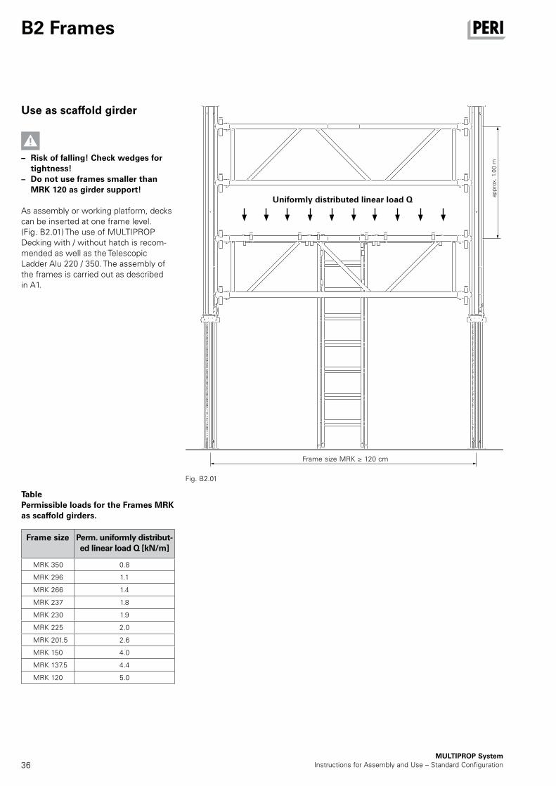
Use as scaffold girder
– Risk of falling! Check wedges for tightness!
– Do not use frames smaller than MRK 120 as girder support!
As assembly or working platform, decks can be inserted at one frame level. (Fig. B2.01) The use of MULTIPROP Decking with / without hatch is recom-mended as well as the Telescopic Ladder Alu 220 / 350. The assembly of the frames is carried out as described in A1.
Fig. B2.01
Uniformly distributed linear load Q
Frame size MRK ≥ 120 cm
app
rox.
1.0
0 m
37MULTIPROP SystemInstructions for Assembly and Use – Standard Configuration
B3 Tables and towers
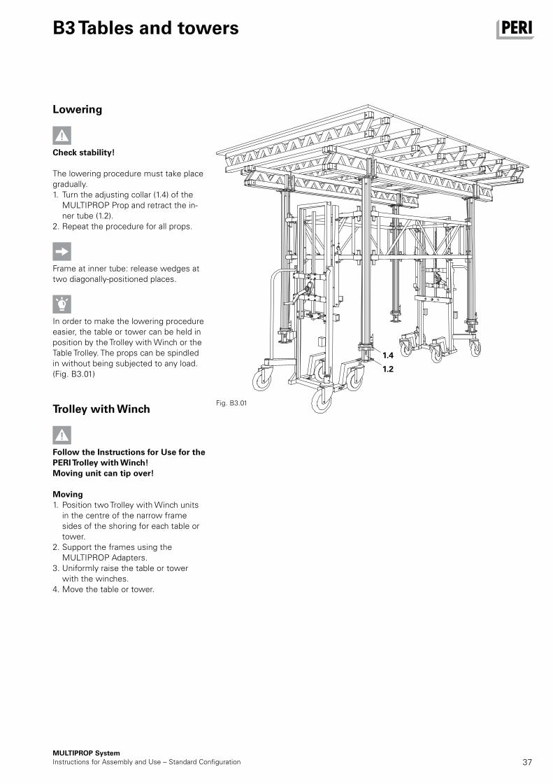
Lowering
Check stability!
The lowering procedure must take place gradually. 1. Turn the adjusting collar (1.4) of the
MULTIPROP Prop and retract the in-ner tube (1.2).
2. Repeat the procedure for all props.
Frame at inner tube: release wedges at two diagonally-positioned places.
In order to make the lowering procedure easier, the table or tower can be held in position by the Trolley with Winch or the Table Trolley. The props can be spindled in without being subjected to any load. (Fig. B3.01)
Trolley with Winch
Follow the Instructions for Use for the PERI Trolley with Winch! Moving unit can tip over!
Moving1. Position two Trolley with Winch units
in the centre of the narrow frame sides of the shoring for each table or tower.
2. Support the frames using the MULTIPROP Adapters.
3. Uniformly raise the table or tower with the winches.
4. Move the table or tower.
Fig. B3.01
1.4
1.2
38
0 – 300 kg 600 cm 600 cm
301 – 400 kg 700 cm 650 cm
401 – 500 kg 800 cm 700 cm
501 – 600 kg 800 cm 700 cm
601 – 800 kg 800 cm 650 cm
801 – 1000 kg 750 cm 600 cm
1001 – 1200 kg 700 cm 550 cm
1201 – 1400 kg 650 cm 550 cm
1401 – 1600 kg 650 cm 500 cm
1601 – 2000 kg 600 cm 500 cm
MRK 350 280
MRK 296 350
MRK 266 – 225 440
MRK 201.5 560
MRK 150 880
MRK 137.5 920
17
16
MULTIPROP SystemInstructions for Assembly and Use – Standard Configuration
B3 Tables and towers
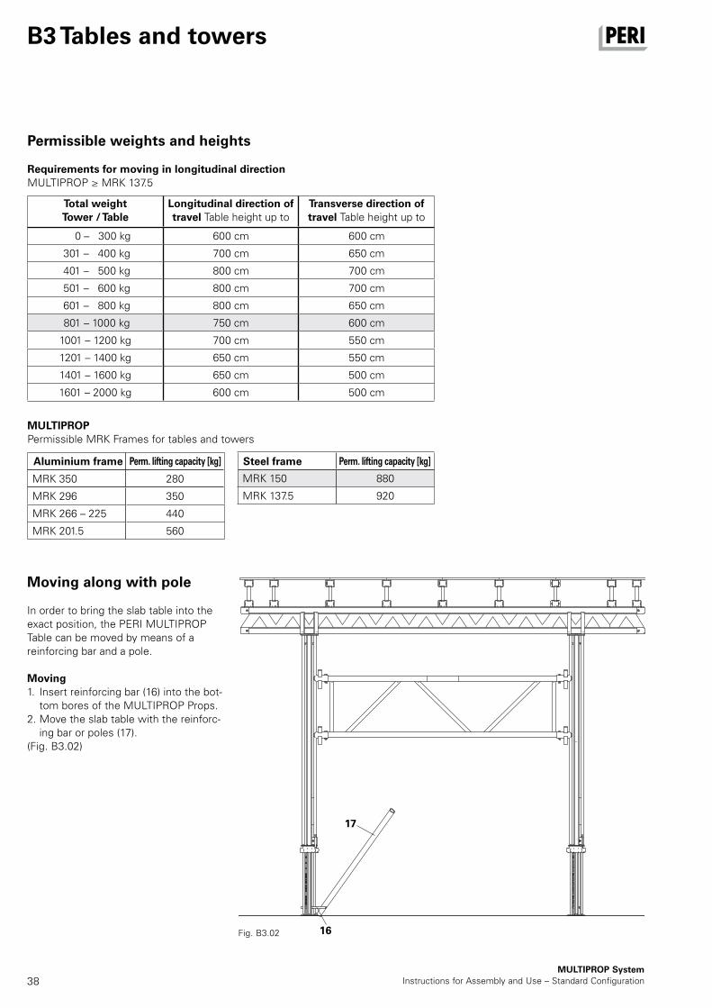
Permissible weights and heights
Requirements for moving in longitudinal directionMULTIPROP ≥ MRK 137.5
Total weightTower / Table
Longitudinal direction of travel Table height up to
Transverse direction of travel Table height up to
MULTIPROPPermissible MRK Frames for tables and towers
Aluminium frame Perm. lifting capacity [kg] Steel frame Perm. lifting capacity [kg]
Moving along with pole
In order to bring the slab table into the exact position, the PERI MULTIPROP Table can be moved by means of a reinforcing bar and a pole.
Moving1. Insert reinforcing bar (16) into the bot-
tom bores of the MULTIPROP Props.2. Move the slab table with the reinforc-
ing bar or poles (17).(Fig. B3.02)
Fig. B3.02
39
MULTIPROP
System
Ausgabe 11 | 2017
Edition 11 | 2017
Typenprüfung | Type Test
MULTIPROP SystemInstructions for Assembly and Use – Standard Configuration
MULTIPROP System
Tables The load-bearing capacity of the shoring towers in the MULTIPROP System is dependent on the position of the MULTIPROP Frames MRK.The values are stated in the relevant current versions of the type test!

MULTIPROP Single Props and System
40
Item no. Weight kg
028390028400028330028340028380028350
9.860 10.100 11.300 14.000 15.400 16.300
MULTIPROP Frames MRK, SteelFrame MRK 62.5Frame MRK 75Frame MRK 90Frame MRK 120Frame MRK 137.5Frame MRK 150Bracing frame for MULTIPROP. For connecting to outer and inner tube. With captive wedge coupling.
L X 545 625 670 750 820 900 1120 1200 1295 1375 1420 1500 NoteL = Loading Length X = Axis Length
L
X
500
027288027289027290027291027305
10.100 15.400 19.400 24.700 34.500
MULTIPROP MPMULTIPROP MP 120MULTIPROP MP 250MULTIPROP MP 350MULTIPROP MP 480MULTIPROP MP 625Slab prop made of aluminium. Used as individual prop as well as in combination with MULTIPROP Frames MRK to form towers.
min. L max. L 800 1200 1450 2500 1950 3500 2600 4800 4300 6250 Technical DataPermissible load: see PERI Design Tables.
1010
minL
maxL
150
64 80 120
Ø40
Ø14
100
87
MULTIPROP Single Props and System
41
Item no. Weight kg
107171107172
12.500 18.500
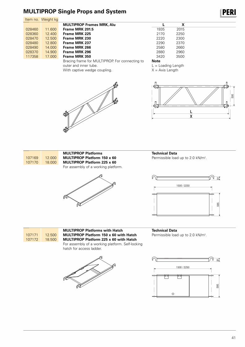
MULTIPROP Platforms with HatchMULTIPROP Platform 150 x 60 with HatchMULTIPROP Platform 225 x 60 with HatchFor assembly of a working platform. Self-locking hatch for access ladder.
Technical DataPermissible load up to 2.0 kN/m2.
1500 / 2250
595
91
107169107170
12.000 18.000
MULTIPROP PlatformsMULTIPROP Platform 150 x 60MULTIPROP Platform 225 x 60For assembly of a working platform.
Technical DataPermissible load up to 2.0 kN/m2.
1500 / 2250
595
91
028460028360028470028480028490028370117358
11.600 12.400 12.500 12.800 14.000 14.900 17.000
MULTIPROP Frames MRK, AluFrame MRK 201.5Frame MRK 225Frame MRK 230Frame MRK 237Frame MRK 266Frame MRK 296Frame MRK 350Bracing frame for MULTIPROP. For connecting to outer and inner tube. With captive wedge coupling.
L X 1935 2015 2170 2250 2220 2300 2290 2370 2580 2660 2880 2960 3420 3500 NoteL = Loading Length X = Axis Length
L
X
500
MULTIPROP Single Props and System
42
Item no. Weight kg
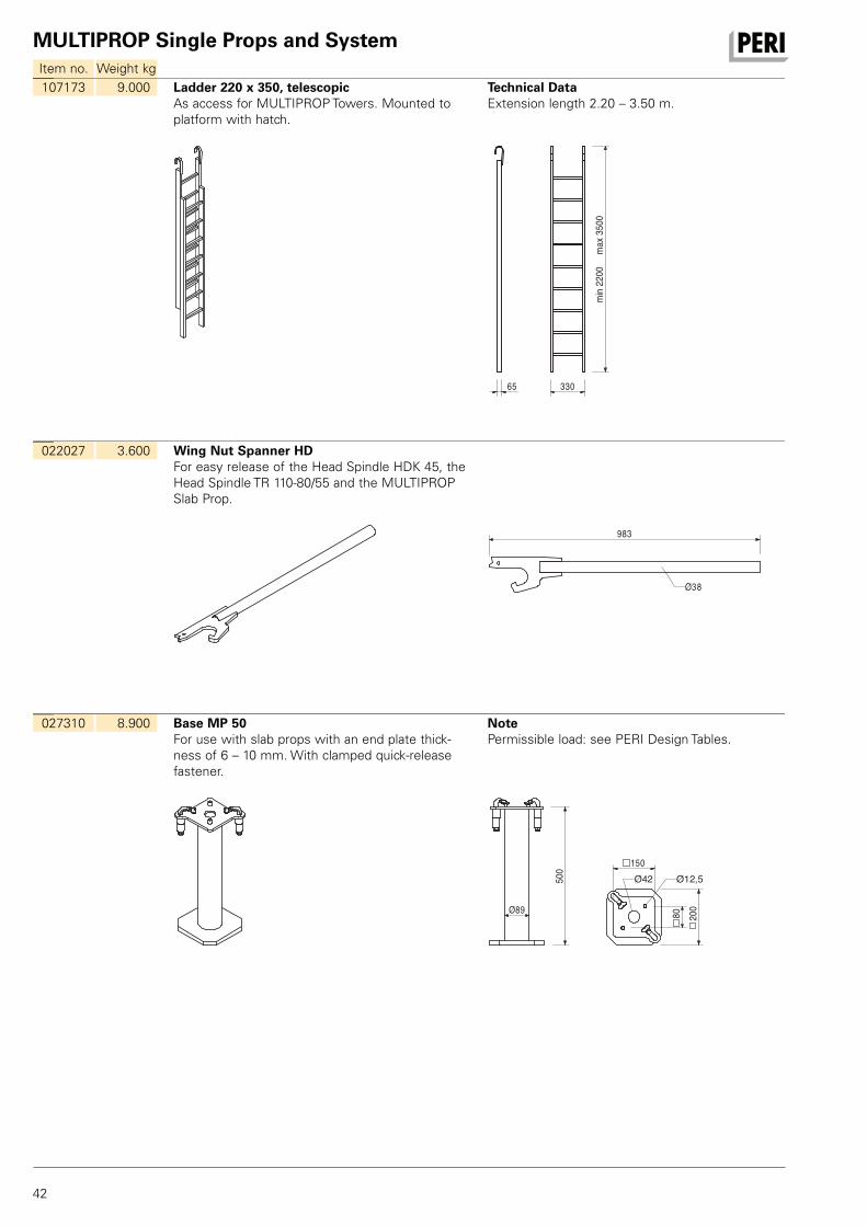
027310 8.900 Base MP 50For use with slab props with an end plate thick-ness of 6 – 10 mm. With clamped quick-release fastener.
NotePermissible load: see PERI Design Tables.
500
89Ø
200
150
80
Ø12,5Ø42
022027 3.600 Wing Nut Spanner HDFor easy release of the Head Spindle HDK 45, the Head Spindle TR 110-80/55 and the MULTIPROP Slab Prop.
983
Ø38
107173 9.000 Ladder 220 x 350, telescopicAs access for MULTIPROP Towers. Mounted to platform with hatch.
Technical DataExtension length 2.20 – 3.50 m.
33065
min
2200
max
3500
MULTIPROP Single Props and System
43
Item no. Weight kg
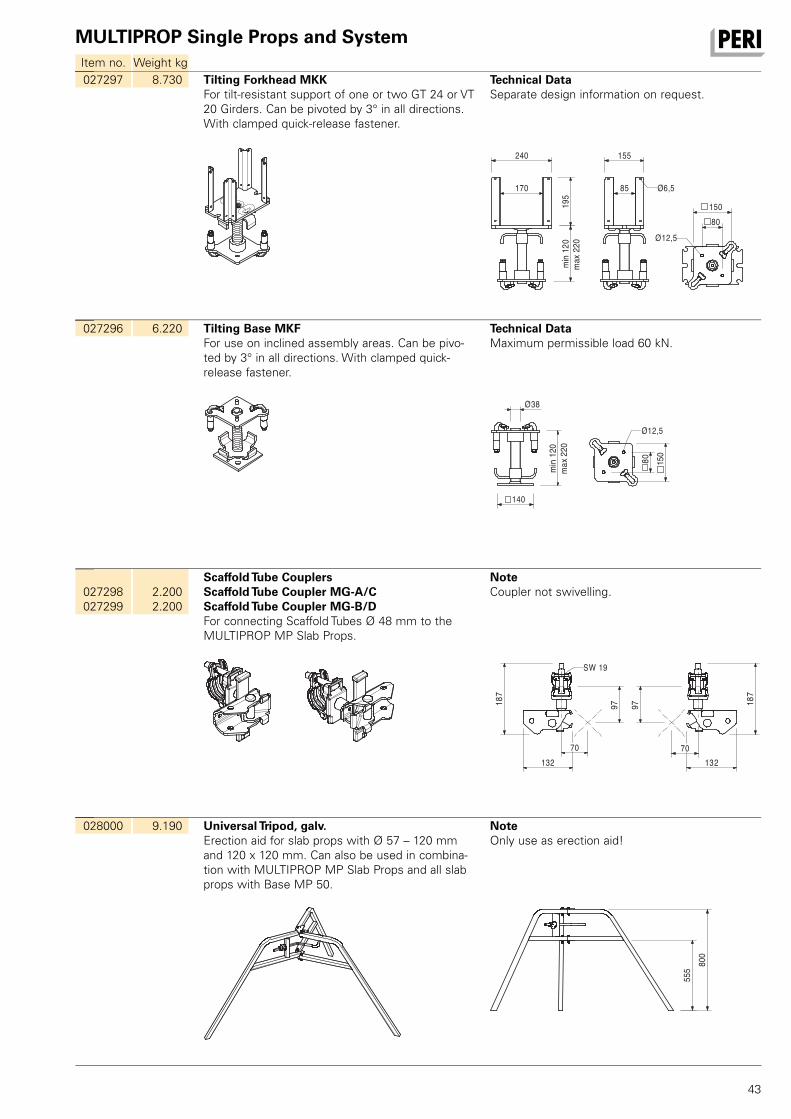
028000 9.190 Universal Tripod, galv.Erection aid for slab props with Ø 57 – 120 mm and 120 x 120 mm. Can also be used in combina-tion with MULTIPROP MP Slab Props and all slab props with Base MP 50.
NoteOnly use as erection aid!
555 80
0
027298027299
2.200 2.200
Scaffold Tube CouplersScaffold Tube Coupler MG-A/CScaffold Tube Coupler MG-B/DFor connecting Scaffold Tubes Ø 48 mm to the MULTIPROP MP Slab Props.
NoteCoupler not swivelling.
132 13270 70
187
187
97 97
SW 19
027296 6.220 Tilting Base MKFFor use on inclined assembly areas. Can be pivo-ted by 3° in all directions. With clamped quick-release fastener.
Technical DataMaximum permissible load 60 kN.
max
220
140
min
120
80 150
38Ø
Ø12,5
027297 8.730 Tilting Forkhead MKKFor tilt-resistant support of one or two GT 24 or VT 20 Girders. Can be pivoted by 3° in all directions. With clamped quick-release fastener.
Technical DataSeparate design information on request.
195
min
120
170
240
85
155
80 150
Ø12,5
Ø6,5
max
220
MULTIPROP Single Props and System
44
Item no. Weight kg
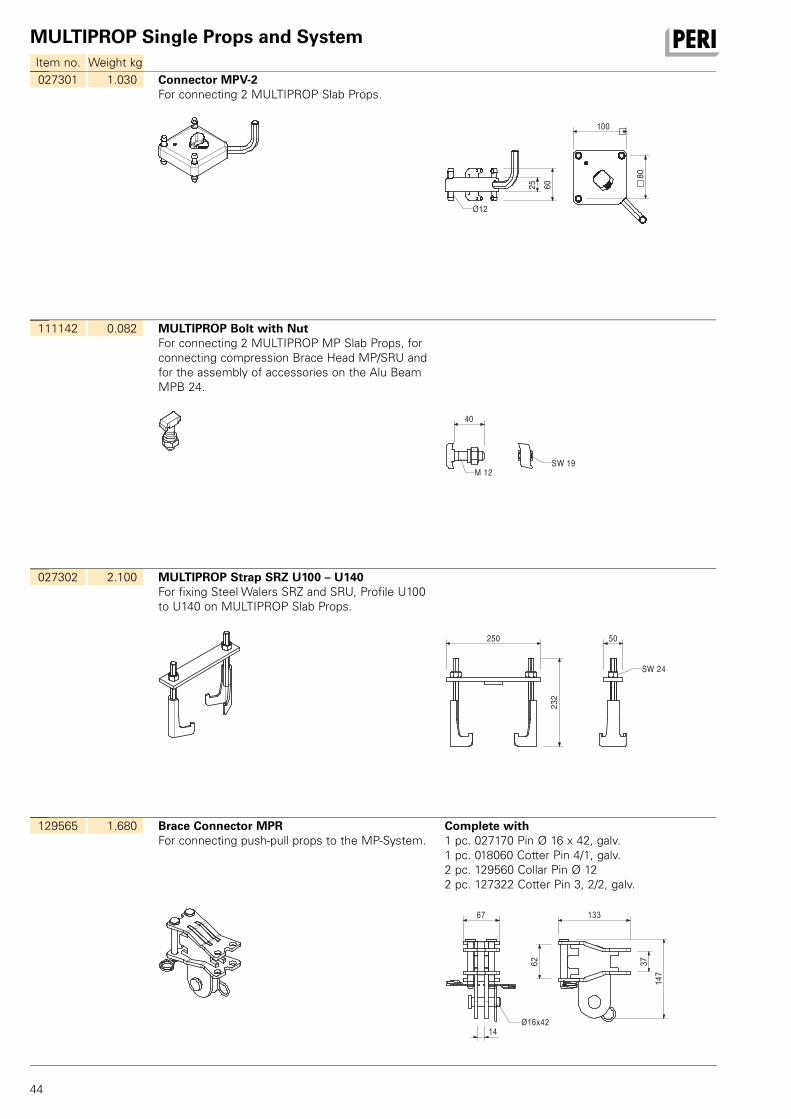
129565 1.680 Brace Connector MPRFor connecting push-pull props to the MP-System.
Complete with1 pc. 027170 Pin Ø 16 x 42, galv.1 pc. 018060 Cotter Pin 4/1, galv.2 pc. 129560 Collar Pin Ø 122 pc. 127322 Cotter Pin 3, 2/2, galv.
147
133
14
67
62
37
Ø16x42
027302 2.100 MULTIPROP Strap SRZ U100 – U140For fixing Steel Walers SRZ and SRU, Profile U100 to U140 on MULTIPROP Slab Props.
232
250 50
SW 24
111142 0.082 MULTIPROP Bolt with NutFor connecting 2 MULTIPROP MP Slab Props, for connecting compression Brace Head MP/SRU and for the assembly of accessories on the Alu Beam MPB 24.
40
M 12SW 19
027301 1.030 Connector MPV-2For connecting 2 MULTIPROP Slab Props.
25 60
100
80
Ø12
MULTIPROP Single Props and System
45
Item no. Weight kg
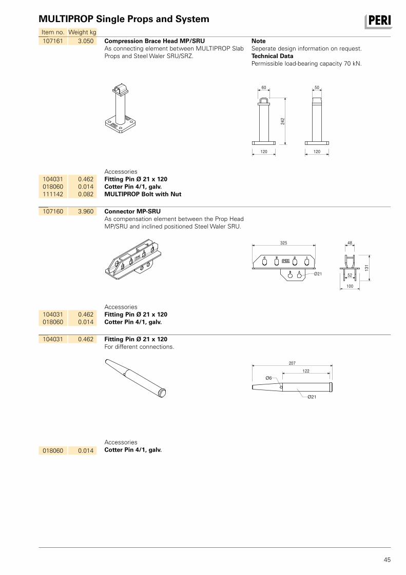
104031 0.462 Fitting Pin Ø 21 x 120For different connections.
207122
Ø6
Ø21
018060 0.014AccessoriesCotter Pin 4/1, galv.
107160 3.960 Connector MP-SRUAs compensation element between the Prop Head MP/SRU and inclined positioned Steel Waler SRU.
325
131
48
52
100
Ø21
104031 018060
0.462 0.014
AccessoriesFitting Pin Ø 21 x 120Cotter Pin 4/1, galv.
107161 3.050 Compression Brace Head MP/SRUAs connecting element between MULTIPROP Slab Props and Steel Waler SRU/SRZ.
NoteSeperate design information on request.Technical DataPermissible load-bearing capacity 70 kN.
120
242
120
5060
104031 018060 111142
0.462 0.014 0.082
AccessoriesFitting Pin Ø 21 x 120Cotter Pin 4/1, galv.MULTIPROP Bolt with Nut
MULTIPROP Single Props and System
46
Item no. Weight kg
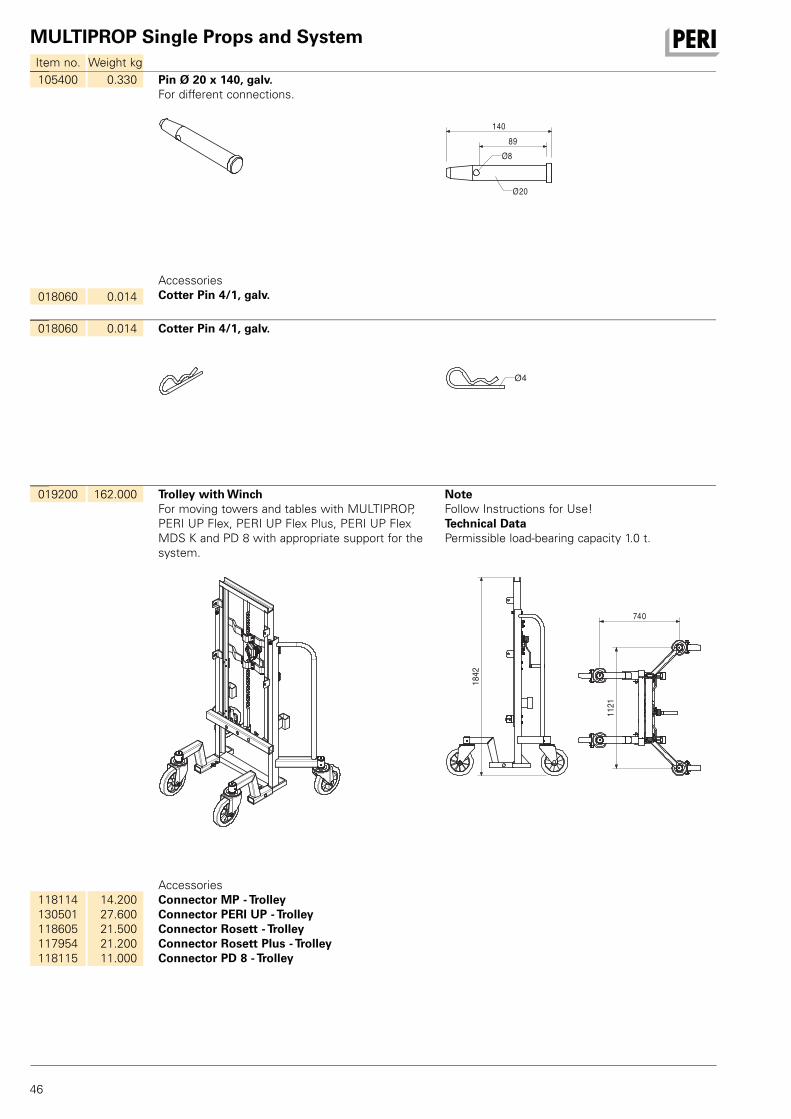
019200 162.000 Trolley with WinchFor moving towers and tables with MULTIPROP, PERI UP Flex, PERI UP Flex Plus, PERI UP Flex MDS K and PD 8 with appropriate support for the system.
NoteFollow Instructions for Use!Technical DataPermissible load-bearing capacity 1.0 t.
1842
1121
740
118114 130501 118605 117954 118115
14.200 27.600 21.500 21.200 11.000
AccessoriesConnector MP - TrolleyConnector PERI UP - TrolleyConnector Rosett - TrolleyConnector Rosett Plus - TrolleyConnector PD 8 - Trolley
018060 0.014 Cotter Pin 4/1, galv.
Ø4
105400 0.330 Pin Ø 20 x 140, galv.For different connections.
89140
Ø8
Ø20
018060 0.014AccessoriesCotter Pin 4/1, galv.
MULTIPROP Single Props and System
47
Item no. Weight kg
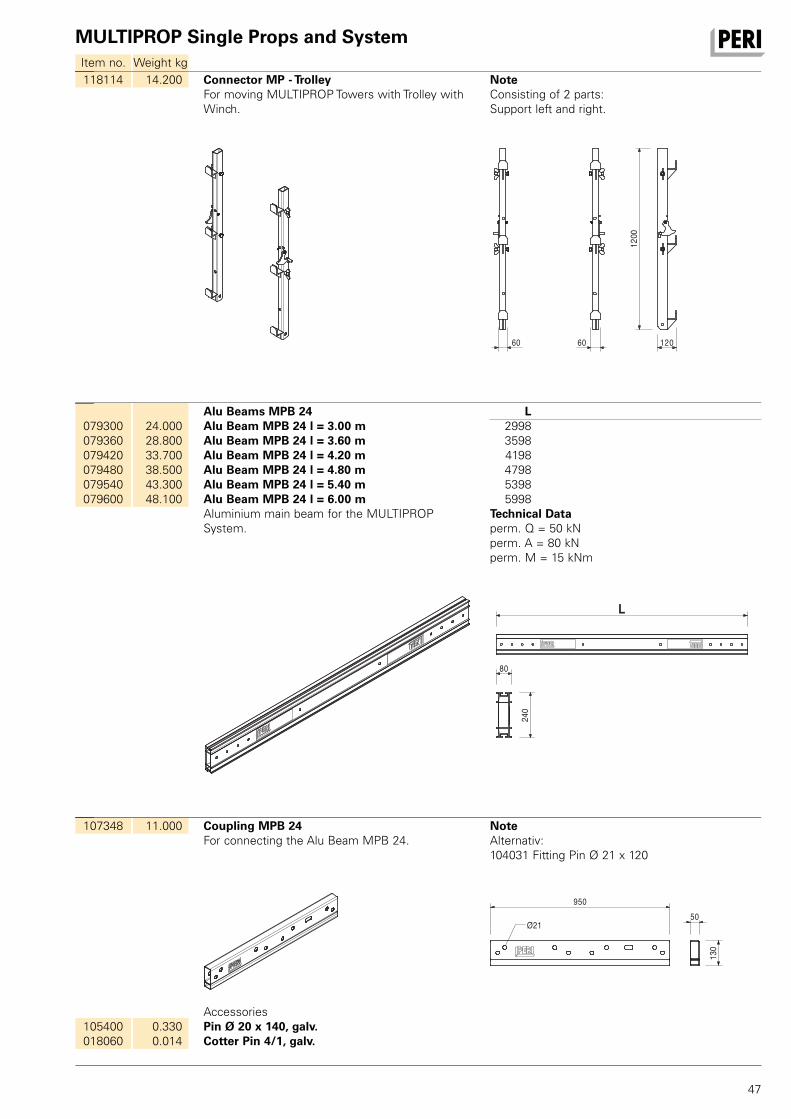
107348 11.000 Coupling MPB 24For connecting the Alu Beam MPB 24.
NoteAlternativ: 104031 Fitting Pin Ø 21 x 120
95050
130
Ø21
105400 018060
0.330 0.014
AccessoriesPin Ø 20 x 140, galv.Cotter Pin 4/1, galv.
079300079360079420079480079540079600
24.000 28.800 33.700 38.500 43.300 48.100
Alu Beams MPB 24Alu Beam MPB 24 l = 3.00 mAlu Beam MPB 24 l = 3.60 mAlu Beam MPB 24 l = 4.20 mAlu Beam MPB 24 l = 4.80 mAlu Beam MPB 24 l = 5.40 mAlu Beam MPB 24 l = 6.00 mAluminium main beam for the MULTIPROP System.
L 2998 3598 4198 4798 5398 5998 Technical Dataperm. Q = 50 kN perm. A = 80 kN perm. M = 15 kNm
L
80
240
118114 14.200 Connector MP - TrolleyFor moving MULTIPROP Towers with Trolley with Winch.
NoteConsisting of 2 parts: Support left and right.
1200
60 60 120
MULTIPROP Single Props and System
48
Item no. Weight kg
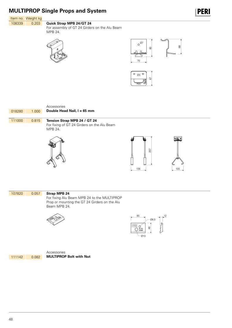
107820 0.057 Strap MPB 24For fixing Alu Beam MPB 24 to the MULTIPROP Prop or mounting the GT 24 Girders on the Alu Beam MPB 24.
65
46
12Ø8,5
Ø13
111142 0.082AccessoriesMULTIPROP Bolt with Nut
111000 0.815 Tension Strap MPB 24 / GT 24For fixing of GT 24 Girders on the Alu Beam MPB 24.
136 105
257
108339 0.203 Quick Strap MPB 24/GT 24For assembly of GT 24 Girders on the Alu Beam MPB 24.
80 68
70
67
Ø7
Ø5
018280 1.000AccessoriesDouble Head Nail, l = 65 mm

MULTIPROP Single Props and System
49
Item no. Weight kg
116292 4.720 Guardrail Post HSGP-2As guardrail for different systems.
35
120
1050
1300
450
65
104131 3.940 Guardrail Holder SRU/SRZFor assembling a guardrail to the Steel Walers SRU and SRZ, Profile U100 to U140.
Complete with2 pc. 105400 Pin Ø 20 x 140, galv.2 pc. 018060 Cotter Pin 4/1, galv.
116292 061260
4.720 6.150
AccessoriesGuardrail Post HSGP-2Guardrail Post SGP
108213 2.590 Brace Connector MPB 24For connecting push-pull props or bracings to Aluminium Beam MPB 24.
267
205
82
Ø22
Ø16,5
14
120
104031 018060
0.462 0.014
AccessoriesFitting Pin Ø 21 x 120Cotter Pin 4/1, galv.

TN
ID
JP
TH
SG
MY
KR
PHVN
AU
AE
LB
TR
MA IL
KZ
RU
ZA
EG
AZ
IN
MZ
TZ
NA
AO
SA
IR
DZJO
NG
OM
US
AR
BR
CO
CL
CA
MX
PE
PA
QAKW
HK
CA PERI Formwork Systems, Inc. www.peri.ca
MX PERI Cimbras y Andamios, S.A. de C.V. www.peri.com.mx
PA PERI Panama Inc. www.peri.com.pa
US PERI Formwork Systems, Inc. www.peri-usa.com
AR PERI S.A. www.peri.com.ar
BR PERI Formas e Escoramentos Ltda. www.peribrasil.com.br
CL PERI Chile Ltda. www.peri.cl
CO PERI S.A.S. www.peri.com.co
PE PERI Peruana S.A.C. www.peri.com.pe
AO Pericofragens, Lda. www.peri.pt
DZ S.A.R.L. PERI www.peri.dz
EG Egypt Branch Office www.peri.com.eg
MA PERI S.A. www.peri.ma
MZ PERI (Pty.) Ltd. www.peri.co.mz
NA PERI (Pty.) Ltd. www.peri.na
NG PERI Nigeria Ltd. www.peri.ng
TN PERI S.A.U. www.peri.es
TZ PERI Formwork and Scaffolding Ltd www.peri.co.tz ZA PERI Formwork Scaffolding (Pty) Ltd www.peri.co.za
AE PERI (L.L.C.) www.peri.ae
AZ PERI Repesentative Office www.peri.com.tr
HK PERI (Hong Kong) Limited www.perihk.com
ID PT Beton Perkasa Wijaksana www.betonperkasa.com
IL PERI F.E. Ltd. www.peri.co.il
IN PERI (India) Pvt Ltd www.peri.in
IR PERI Pars. Ltd. www.peri.ir
JO PERI GmbH – Jordan www.peri.com
JP PERI Japan K.K. www.peri.co.jp
KR PERI (Korea) Ltd. www.perikorea.com
KW PERI Kuwait W.L.L. www.peri.com.kw
KZ TOO PERI Kazakhstan www.peri.kz
LB PERI Lebanon Sarl [email protected]
MY PERI Formwork Malaysia Sdn. Bhd. www.perimalaysia.com
OM PERI (L.L.C.) www.peri.ae
PH PERI-Asia Philippines, INC. www.peri.com.ph
QA PERI Qatar LLC www.peri.qa
SA PERI Saudi Arabia Ltd. www.peri.com.sa
SG PERI Asia Pte Ltd www.periasia.com
TH Peri (Thailand) Co., Ltd. www.peri.co.th
TR PERI Kalıp ve İskeleleri www.peri.com.tr
VN PERI ASIA PTE LTD www.peri.com.vn
North America
Canada
Mexico
Panama
USA
South America
Argentina
Brazil
Chile
Colombia
Peru
Africa
Angola
Algeria
Egypt
Morocco
Mozambique
Namibia
Nigeria
Tunisia
Tanzania
South Africa
Asia
United Arab Emirates
Azerbaijan
Hong Kong
Indonesia
Israel
India
Iran
Jordan
Japan
Korea
Kuwait
Kazakhstan
Lebanon
Malaysia
Oman
Philippines
Qatar
Saudi Arabia
Singapore
Thailand
Turkey
Vietnam
PERI International

FR
DE
CH
ES
BE
NL
IT
GB
LU
IR
TR
HUAT
CZ
DK
FI
NO
SE
PL
PT
ROSI
SK
EE
GR
LV
LT
BG
IS
UA
RS
BY
RU
HR
BA
AL
AU PERI Australia Pty. Ltd. www.periaus.com.au
AL PERI Kalıp ve İskeleleri www.peri.com.tr
AT PERI Ges.mbH www.peri.at
BA PERI oplate i skele d.o.o www.peri.com.hr
BE PERI N.V. www.peri.be
BG PERI Bulgaria EOOD www.peri.bg
BY IOOO PERI www.peri.by
CH PERI AG www.peri.ch
CZ PERI spol. s r.o. www.peri.cz
DE PERI GmbH www.peri.de
DK PERI Danmark A/S www.peri.dk
EE PERI AS www.peri.ee
ES PERI S.A.U. www.peri.es
FI PERI Suomi Ltd. Oy www.perisuomi.fi
FR PERI S.A.S. www.peri.fr
GB PERI Ltd. www.peri.ltd.uk
GR PERI Hellas Ltd. www.perihellas.gr
HR PERI oplate i skele d.o.o. www.peri.com.hr
HU PERI Kft. www.peri.hu
IR Siteserv Access & Formwork www.siteservaccess.ie
IS Armar ehf. www.armar.is
IT PERI S.r.l. www.peri.it
LT PERI UAB www.peri.lt
LU N.V. PERI S.A. www.peri.lu
LV PERI SIA www.peri-latvija.lv
NL PERI b.v. www.peri.nl
NO PERI Norge AS www.peri.no
PL PERI Polska Sp. z o.o. www.peri.com.pl
PT Pericofragens Lda. www.peri.pt
RO PERI România SRL www.peri.ro
RS PERI oplate d.o.o. www.peri.rs
RU OOO PERI www.peri.ru
SE PERI Sverige AB www.peri.se
SI PERI oplate i skele d.o.o www.peri.com.hr
SK PERI spol. s. r.o. www.peri.sk
UA TOW PERI www.peri.ua
Oceania
Australia
Europe
Albania
Austria
Bosnia and Herzegovina
Belgium
Bulgaria
Belorussia
Switzerland
Czech Republic
Germany
Denmark
Estonia
Spain
Finland
France
United Kingdom
Greece
Croatia
Hungary
Ireland
Iceland
Italy
Lithuania
Luxembourg
Latvia
Netherlands
Norway
Poland
Portugal
Romania
Serbia
Russia
Sweden
Slovania
Slovakia
Ukraine
PERI GmbHFormwork Scaffolding EngineeringRudolf-Diesel-Strasse 1989264 WeissenhornGermanyTel. +49 (0)7309.950-0Fax +49 (0)[email protected]
PERI GmbHFormwork Scaffolding EngineeringRudolf-Diesel-Strasse 1989264 WeissenhornGermanyTel. +49 (0)7309.950-0Fax +49 (0)[email protected]
DE
en
05
| 20
18 3
sm 7
917
20
© P
ER
I Gm
bH
The optimal System for every Project and every Requirement
System-Independent Accessories
Column FormworkWall Formwork Slab Formwork
Climbing Systems Bridge Formwork Tunnel Formwork Shoring Systems
Construction Scaffold Industrial ScaffoldFacade Scaffold Access
Protection Scaffold Safety Systems Services


![28728452 Slab Formwork Design[1]](https://static.fdocuments.us/doc/165x107/577d347c1a28ab3a6b8e1dca/28728452-slab-formwork-design1.jpg)