AIR VACUUM GUN - Harbor Freight Toolsimages.harborfreight.com/manuals/66000-66999/66282.pdfAIR...
15
AIR VACUUM GUN 66282 SET UP AND OPERATING INSTRUCTIONS Distributed exclusively by Harbor Freight Tools ® . 3491 Mission Oaks Blvd., Camarillo, CA 93011 Visit our website at: http://www.harborfreight.com Read this material before using this product. Failure to do so can result in serious injury. SAVE THIS MANUAL. Copyright © 2008 by Harbor Freight Tools ® . All rights reserved. No portion of this manual or any artwork contained herein may be reproduced in any shape or form without the express written consent of Harbor Freight Tools. Diagrams within this manual may not be drawn proportionally. Due to continuing improvements, actual product may differ slightly from the product described herein. Tools required for assembly and service may not be included. For technical questions or replacement parts, please call 1-800-444-3353.
Transcript of AIR VACUUM GUN - Harbor Freight Toolsimages.harborfreight.com/manuals/66000-66999/66282.pdfAIR...

AIR VACUUM GUN66282
Set Up ANd OpeRAtING INStRUCtIONS
distributed exclusively by Harbor Freight tools®.3491 Mission Oaks Blvd., Camarillo, CA 93011
Visit our website at: http://www.harborfreight.com
Read this material before using this product. Failure to do so can result in serious injury. SAVe tHIS MANUAl.
Copyright© 2008 by Harbor Freight Tools®. All rights reserved. No portion of this manual or any artwork contained herein may be reproduced in any shape or form without the express written consent of Harbor Freight Tools. Diagrams within this manual may not be drawn proportionally. Due to continuing improvements, actual product may differ slightly from the product described herein. Tools required for assembly and service may not be included.
For technical questions or replacement parts, please call 1-800-444-3353.

SKU 66282 For technical questions, please call 1-800-444-3353. Page 2
CONteNtSSAVe tHIS MANUAl .................... 3
SAFety AleRt SyMbOl ANd SIGNAl WORdS .............................3
IMpORtANt SAFety INStRUCtIONS .......................... 3
GeNeRAl ...........................................3WORk AReA ......................................3peRSONAl SAFety .........................4tOOl USe ANd CARe ......................4SeRVICe ............................................5AIR SOURCe ......................................5
SyMbOlS ANd SpeCIFIC SAFety INStRUCtIONS ........... 5
SyMbOl deFINItIONS .....................5SpeCIFIC SAFety INStRUCtIONS 6
FUNCtIONAl deSCRIptION ....... 7SpeCIFICAtIONS ..............................7COMpONeNtS ANd CONtROlS ....7
INItIAl tOOl Set Up/ASSeMbly .................................. 7
UNpACkING .......................................7AIR SUpply .......................................8
OpeRAtING INStRUCtIONS ...... 9tOOl Set Up ....................................9WORk pIeCe ANd WORk AReA
Set Up ............................................9INStAllING tHe
COlleCtION bAG ..................10GeNeRAl OpeRAtING
INStRUCtIONS ............................10
USeR-MAINteNANCe INStRUCtIONS ........................ 11
CleANING ANd MAINteNANCe ... 11tROUbleSHOOtING ......................12
pARtS lISt ................................. 13
ASSeMbly dIAGRAM ................ 14
lIMIted 90 dAy WARRANty .... 15

SKU 66282 For technical questions, please call 1-800-444-3353. Page 3
SAVe tHIS MANUAlKeep this manual for the safety warn-
ings and precautions, assembly, operat-ing, inspection, maintenance and cleaning procedures. Write the product’s serial number in the back of the manual near the Warranty statement (or month and year of purchase if product has no number). Keep this manual and the receipt in a safe and dry place for future reference.
Safety Alert Symbol and Signal Words
In this manual, on the labeling, and all other information provid-ed with this product:
this is the safety alert symbol. It is used to alert you to potential personal injury hazards. Obey all safety messages that follow this symbol to avoid possible injury or death.
dANGeR indicates a hazardous
situation which, if not avoided, will result in death or serious injury.
WARNING indicates a
hazardous situation which, if not avoided, could result in death or serious injury.
CAUtION, used with the safety
alert symbol, indicates a hazardous situation which, if not avoided, could result in minor or moderate injury.
NOtICe is used to address practices
not related to personal injury.
CAUtION, without the safety alert
symbol, is used to address practices not related to personal injury.
IMpORtANt SAFety INStRUCtIONS
INStRUCtIONS peRtAINING tO A RISk OF FIRe,
eleCtRIC SHOCk, OR INjURy tO peRSONS
WARNING – When using tools, basic pre-cautions should always be followed, including the following:
Generalto reduce the risks of electric a. shock, fire, and injury to persons, read all the instructions before us-ing the tool.
Work areakeep the work area clean and well a. lighted. Cluttered benches and dark areas increase the risks of electric shock, fire, and injury to persons.
do not operate the tool in explo-b. sive atmospheres, such as in the presence of flammable liquids, gases, or dust. The tool is able to create sparks resulting in the ignition of the dust or fumes.
Keep bystanders, children, and c. visitors away while operating the

SKU 66282 For technical questions, please call 1-800-444-3353. Page 4
tool. Distractions are able to result in the loss of control of the tool.
personal safetyStay alert. Watch what you are do-a. ing and use common sense when operating the tool. Do not use the tool while tired or under the influ-ence of drugs, alcohol, or medica-tion. A moment of inattention while operating the tool increases the risk of injury to persons.
dress properly. do not wear loose b. clothing or jewelry. Contain long hair. keep hair, clothing, and gloves away from moving parts. Loose clothes, jewelry, or long hair increases the risk of injury to persons as a result of being caught in moving parts.
Avoid unintentional starting. be c. sure the switch is off before con-necting to the air supply. Do not carry the tool with your finger on the switch or connect the tool to the air supply with the switch on.
Remove adjusting keys and d. wrenches before turning the tool on. A wrench or a key that is left at-tached to a rotating part of the tool increases the risk of personal injury.
do not overreach. keep proper e. footing and balance at all times. Proper footing and balance enables better control of the tool in unexpect-ed situations.
f. Use safety equipment. A dust mask, non-skid safety shoes and a hard hat must be used for the applicable
conditions. Wear heavy-duty work gloves during use.
g. Always wear eye protec-tion. Wear ANSI-ap-proved safety goggles.
h. Always wear hearing protection when using the tool. Prolonged expo-sure to high intensity noise
is able to cause hearing loss.
Risk of electric Shock. this tool i. is not provided with an insulated gripping surface. Contact with a ″live″ wire will also make exposed metal parts of the tool ″live″ and shock the operator.
Avoid body contact with grounded j. surfaces such as pipes, radiators, ranges and refrigerators. There is an increased risk of electric shock if your body is grounded.
tool use and caredo not force the tool. a. Use the correct tool for the application. The correct tool will do the job better and safer at the rate for which the tool is designed.
do not use the tool if the switch b. does not turn the tool on or off. Any tool that cannot be controlled with the switch is dangerous and must be repaired.
disconnect the tool from the air c. source before making any adjust-ments, changing accessories, or storing the tool. Such preventive safety measures reduce the risk of starting the tool unintentionally. Turn off and detach the air supply, safely

SKU 66282 For technical questions, please call 1-800-444-3353. Page 5
discharge any residual air pressure, and release the throttle and/or turn the switch to its off position before leaving the work area.
Store the tool when it is idle out of d. reach of children and other un-trained persons. A tool is dangerous in the hands of untrained users.
Check for misalignment or bind-e. ing of moving parts, breakage of parts, and any other condition that affects the tool’s operation. If dam-aged, have the tool serviced before using. Many accidents are caused by poorly maintained tools. There is a risk of bursting if the tool is damaged.
Use only accessories that are f. identified by the manufacturer for the specific tool model. Use of an accessory not intended for use with the specific tool model, increases the risk of injury to persons.
ServiceTool service must be performed a. only by qualified repair personnel.
When servicing a tool, use only b. identical replacement parts. Use only authorized parts.
Use only the lubricants supplied c. with the tool or specified by the manufacturer.
Air sourcea. Never connect to an air
source that is capable of exceeding 90 psi. Over pressurizing the tool may
cause bursting, abnormal operation, breakage of the tool or serious injury
to persons. Use only clean, dry, regulated compressed air at the rated pressure or within the rated pressure range as marked on the tool. Always verify prior to using the tool that the air source has been adjusted to the rated air pressure or within the rated air-pressure range.
Never use oxygen, carbon dioxide, b. combustible gases or any bottled gas as an air source for the tool. Such gases are capable of explosion and serious injury to persons.
SAVe tHeSe INStRUCtIONS.
SyMbOlS ANd SpeCIFIC SAFety
INStRUCtIONSSymbol Definitions
Symbol property or statement
no No-load speed
.../min Revolutions or reciprocation per minute
pSI Pounds per square inch of pressure
ft-lb Foot-pounds of torque
bpM Blows per minute
CFM Cubic Feet per Minute flow
SCFM Cubic Feet per Minute flow at standard conditions
Npt National pipe thread, tapered
NpS National pipe thread, straight
Chart continued in next column.

SKU 66282 For technical questions, please call 1-800-444-3353. Page 6
Symbol DefinitionsSymbol property or statement
WARNING marking concerning Risk of Eye Injury. Wear ANSI-approved eye protection.WARNING marking concerning Risk of Hearing Loss. Wear hearing protection.WARNING marking concerning Risk of Respiratory Injury. Wear NIOSH-approved dust mask/respirator.
WARNING marking concerning Risk of Explosion.
Specific Safety InstructionsThe warnings and precautions dis-1. cussed in this manual cannot cover all possible conditions and situations that may occur. It must be under-stood by the operator that common sense and caution are factors which cannot be built into this product, but must be supplied by the operator.
WARNING: Some dust created by power sanding, sawing, grinding, drilling, and other construction activities, con-tains chemicals known [to the State of California] to cause cancer, birth defects or other reproductive harm. Some examples of these chemicals are: • Lead from lead-based paints • Crystalline silica from bricks and cement or other masonry products • Arsenic and chromium from chemi-cally treated lumber Your risk from these exposures var-ies, depending on how often you do this type of work. To reduce your exposure to these chemicals: work in a well ventilated area, and work with approved safety equipment, such as
those dust masks that are specially designed to filter out microscopic particles. (California Health & Safety Code § 25249.5, et seq.)
WARNING: The brass components of this product contain lead, a chemical known to the State of California to cause birth defects (or other repro-ductive harm). (California Health & Safety code § 25249.5, et seq.)
Only use with accessories rated to 2. handle the forces exerted by this tool during operation. Other accessories not designed for the forces gener-ated may break and forcefully launch pieces.
Attach all accessories properly to the 3. tool before connecting the air sup-ply. A loose accessory may detach or break during operation.
Obey the manual for the air compres-4. sor used to power this tool.
Install an in-line shutoff valve to allow 5. immediate control over the air supply in an emergency, even if a hose is ruptured.
If the tool requires more force to 6. accomplish the task, verify that the tool receives sufficient, unobstructed airflow (CFM) and increase the pressure (PSI) output of the regulator up to the maximum air pressure rating of this tool.
CAUtION! tO pReVeNt tOOl ANd ACCeSSORy FAIlURe, ReSUlt-ING IN INjURy: do not exceed the tool’s maximum air pressure rating. If the tool still does not have sufficient force at maximum pressure and suf-

SKU 66282 For technical questions, please call 1-800-444-3353. Page 7
ficient airflow, then a larger tool may be required.
To prevent accidents, turn off the 7. tool, detach the air supply, safely discharge any residual air pressure in the tool, and release the throttle and/or turn the switch to its off position after use. Clean external surfaces of the tool with clean, dry cloth, and apply a thin coat of tool oil. Then store the tool indoors out of children’s reach.
SAVe tHeSe INStRUCtIONS.
FUNCtIONAl deSCRIptIONSpecifications
Air Consumption 5 SCFM @90 PSI
Maximum Air Pressure 90 PSI
Air Inlet 1/4" -18 NPT (Female)
Fig. 1
Suction created by high-pressure air rushing out
back of gun - dust & chips drawn in
Button Trigger (9)Releases high-pressure air
INTERNAL AIR FLOW
High-Pressure air inlet
Dust & chips drawn in go to bag through hose.
Output Port
Components and Controls
Fig. 2
Button Trigger (9)
Air Inlet Coupling (10)
Outlet PortVacuum: Direction of air flow
Extension Nozzle (8)
INItIAl tOOl Set Up/ASSeMbly
Read the eNtIRe IMpORtANt SAFety INFORMAtION section at the beginning of this manual including all text under subheadings therein before set up or use of this product.
Note: For additional information regarding the parts listed in the following pages, refer to the Assembly Diagram near the end of this manual.
UnpackingWhen unpacking, make sure that
the item is intact and undamaged. If any parts are missing or broken, please call Harbor Freight Tools at the number shown throughout the manual as soon as pos-sible.
This air tool may be shipped with a • protective plug covering the air inlet. Remove this plug before set up.
SKU 66282 For technical questions, please call 1-800-444-3353. Page 8
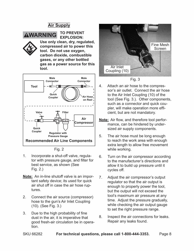
Air Supply tO pReVeNt
explOSION: Use only clean, dry, regulated, compressed air to power this tool. do not use oxygen, carbon dioxide, combustible gases, or any other bottled gas as a power source for this tool.
Fig. 2
1. Incorporate a shut-off valve, regula-tor with pressure gauge, and filter for best service, as shown (See Fig. 2.)
Note: An in-line shutoff valve is an impor-tant safety device; its used for quick air shut off in case the air hose rup-tures.
Connect the air source (compressor) 2. hose to the gun’s Air Inlet Coupling (10). (See Fig. 3.)
Due to the high probability of fine 3. dust in the air, it is imperative that good fresh-air circulation be in opera-tion.
Fig. 3
Air Inlet Coupling (10)
Fine Mesh Screen
4. Attach an air hose to the compres-sor’s air outlet. Connect the air hose to the Air Inlet Coupling (10) of the tool (See Fig. 3.). Other components, such as a connector and quick cou-pler, will make operation more effi-cient, but are not mandatory.
Note: Air flow, and therefore tool perfor-mance, can be hindered by under-sized air supply components.
The air hose must be long enough 5. to reach the work area with enough extra length to allow free movement while working.
Turn on the air compressor according 6. to the manufacturer’s directions and allow it to build up pressure until it cycles off.
Adjust the air compressor’s output 7. regulator so that the air output is enough to properly power the tool, but the output will not exceed the tool’s maximum air pressure at any time. Adjust the pressure gradually, while checking the air output gauge to set the right pressure range.
Inspect the air connections for leaks. 8. Repair any leaks found.

SKU 66282 For technical questions, please call 1-800-444-3353. Page 9
If the tool will not be used at this 9. time, turn off and detach the air sup-ply, safely discharge any residual air pressure, and release the throttle and/or turn the switch to its off posi-tion to prevent accidental operation.
Note: Residual air pressure should not be present after the tool is disconnected from the air supply. However, it is a good safety measure to attempt to discharge the tool in a safe fashion after disconnecting to ensure that the tool is disconnected and unpowered.
OpeRAtING INStRUCtIONS Read the eNtIRe IMpORtANt
SAFety INFORMAtION section at the beginning of this manual including all text under subheadings therein before set up or use of this product.
Inspect tool before use, looking for damaged, loose, and missing parts. If any problems are found, do not use tool until repaired.
tool Set Up tO pReVeNt
SeRIOUS INjURy FROM ACCIdeNtAl OpeRAtION: turn off the tool, detach the air supply, safely discharge any residual air pressure in the tool, and release the throttle and/or turn the switch to its off position before performing any inspection, maintenance, or cleaning procedures.
tO pReVeNt SeRIOUS INjURy: do not adjust or tamper with any control or component in a way not specifically explained within this manual. Improper adjustment can result in tool failure or other serious hazards.
The only adjustment to be made with 1. this tool would be to adjust the PSI level at the air source (compressor).
Work piece and Work Area Set UpRoute the air hose along a safe route 1. to reach the work area without creat-ing a tripping hazard or exposing the air hose to possible damage. The air hose must be long enough to reach the work area with enough extra length to allow free movement while working.
Fig. 4
Large Diameter Output Port
2. Slip the flexible end of the Flexible Hose (6) over the outlet port at the back of the gun. (See Figs. 4, 5.)

SKU 66282 For technical questions, please call 1-800-444-3353. Page 10
Fig. 5
Flexible End of Hose
Screw Clamp (4)
a. Tighten the Screw Clamp (4), secur-ing the hose. (See Fig. 5.)
Installing the Collection bag
The Collection Bag (7) goes on the 3. far end of the Flexible Hose (6).
Fig. 5
Collection Bag Slides on Here
Hard Plastic Fitting
4. The Collection Bag end of the Flex-ible Hose has a hard plastic fitting to hold the Collection Bag. The hook is for hanging the collection bag end.
Fig. 6
Collection Bag (7)
Screw Clamp (4)
5. The open end of the Collection Bag fits over the hard plastic fitting, and like the flexible end of the hose, is secured in place with a Screw Clamp (4). (See Fig. 6.)
General Operating InstructionsWith the Output Hose and Collection 1. Bag and compressor hose connect-ed, put the white plastic nozzle near the material to be vacuumed.
Push the Button Trigger (9) releasing 2. air from the air source.
Rushing air enters the gun chamber 3. through multiple holes in the chamber walls traveling at hight speed back-wards towards the Collection Bag.
A vacuum effect is created at the front 4. nozzle and dust and other particles are drawn in through the nozzle, to the outlet port, through the Flexible Hose and to the Collection Bag.
To clean out bag, loosen the Screw 5. Clamp and remove the bag from the end of the Flexible Hose.Hold the bag, open end pointing into a. a trash can or dust bin, and shake the upper portion of the bag.

SKU 66282 For technical questions, please call 1-800-444-3353. Page 11
Continue until the bag is clear of b. dust and particles.
USeR-MAINteNANCe INStRUCtIONS
Procedures not specifically explained in this manual must be performed only by a qualified technician.
tO pReVeNt SeRIOUS INjURy
FROM ACCIdeNtAl OpeRAtION: turn off the tool, detach the air supply, safely discharge any residual air pressure in the tool, and release the throttle and/or turn the switch to its off position before performing any inspection, maintenance, or cleaning procedures.
tO pReVeNt SeRIOUS INjURy FROM tOOl FAIlURe:do not use damaged equipment. If abnormal noise, vibration, or leaking air occurs, have the problem corrected before further use.
Cleaning and MaintenanceNote: These procedures are in addition to
the regular checks and maintenance explained as part of the regular op-eration of the air-operated tool.
Clean out Collection Bag (7) after 1. every use. (See “General Operating Instructions” Step 5.) A clean bag allows air to move freely with least amount of strain on air source.
daily - Air Supply Maintenance: 2. Every day, perform maintenance on the air supply according to the com-ponent manufacturers’ instructions. The moisture filter must be regularly drained. Performing routine mainte-nance on the air supply will allow the tool to operate more safely and will also reduce wear on the tool.
Quarterly (every 3 months) - tool 3. disassembly, Cleaning, and In-spection: Clean out fine mesh air inlet screen found inside of the Air Inlet Coupling (See Fig. 3.) Check Flexible Hose for splits or tears. Check Collection Bag for worn spots or rips. Check Collec-tion Bag (see Fig. 6) for loose seams and cut or frayed threads.

SKU 66282 For technical questions, please call 1-800-444-3353. Page 12
troubleshootingproblem possible Causes likely Solutions
Decreased output.
Not enough air pressure and/1. or air flow.
Obstructed trigger. 2.
Low air flow entering the gun. 3.
Air leaking from loosely 4. assembled components.
Mechanism contaminated. 5.
Check for loose connections and make sure 1. that air supply is providing enough air flow (CFM) at required pressure (PSI) to the tool’s air inlet. do not exceed maximum air pressure.Clean around trigger to ensure free 2. movement.Clean air inlet screen of buildup. 3.
Make sure housing is properly assembled 4. and tight.Have qualified technician clean and lubricate 5. mechanism. Install in-line filter in air supply as stated in Initial Set Up: Air Supply.
Severe air leakage.(Slight air leakage is normal, especially on older tools.)
Cross-threaded housing 1. components.
Damaged valve or housing.2. Dirty, worn or damaged valve. 3.
Check for incorrect alignment and uneven 1. gaps. If cross-threaded, disassemble and replace damaged parts before use.Replace damaged components.2. Clean or replace valve assembly.3.
Follow all safety precautions whenever diagnosing or servicing the tool. disconnect air supply before service.

SKU 66282 For technical questions, please call 1-800-444-3353. Page 13
pleASe ReAd tHe FOllOWING CAReFUlly
THE MANUFACTURER AND/OR DISTRIBUTOR HAS PROVIDED THE PARTS LIST AND ASSEMBLY DIAGRAM IN THIS MANUAL AS A REFERENCE TOOL ONLY. NEITHER THE MANUFACTURER OR DISTRIBUTOR MAKES ANY REPRESENTATION OR WARRANTY OF ANY KIND TO THE BUYER THAT HE OR SHE IS qUALIFIED TO MAKE ANY REPAIRS TO THE PRODUCT, OR THAT HE OR SHE IS qUALIFIED TO REPLACE ANY PARTS OF THE PRODUCT. IN FACT, THE MANUFACTURER AND/OR DISTRIBUTOR ExPRESSLY STATES THAT ALL REPAIRS AND PARTS REPLACEMENTS SHOULD BE UNDERTAKEN BY CERTIFIED AND LICENSED TECHNICIANS, AND NOT BY THE BUYER. THE BUYER ASSUMES ALL RISK AND LIABILITY ARISING OUT OF HIS OR HER REPAIRS TO THE ORIGINAL PRODUCT OR REPLACEMENT PARTS THERETO, OR ARISING OUT OF HIS OR HER INSTALLATION OF REPLACEMENT PARTS THERETO.
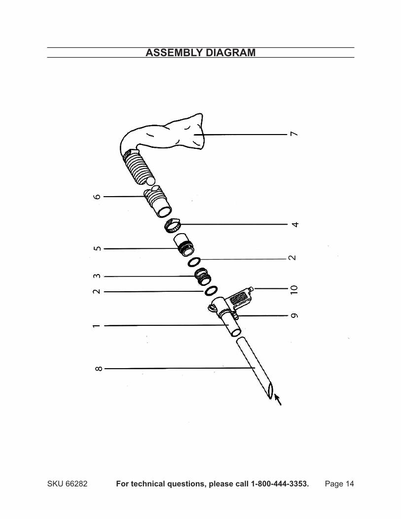
pARtS lIStpart description Qty
1 Main Body 12 O-Ring 23 Valve 14 Screw Clamp 25 Output Port 16 Flexible Hose 17 Collection Bag 18 Extension Nozzle 19 Button Trigger 1
10 Air Inlet Coupling 1
SKU 66282 For technical questions, please call 1-800-444-3353. Page 14
ASSeMbly dIAGRAM
2

SKU 66282 For technical questions, please call 1-800-444-3353. Page 15
Record product’s Serial Number Here: Note: If product has no serial number, record month and year of purchase instead.
Note: Some parts are listed and shown for illustration purposes only, and are not avail-able individually as replacement parts.
lIMIted 90 dAy WARRANtyHarbor Freight Tools Co. makes every effort to assure that its products meet high
quality and durability standards, and warrants to the original purchaser that this prod-uct is free from defects in materials and workmanship for the period of 90 days from the date of purchase. This warranty does not apply to damage due directly or indirectly, to misuse, abuse, negligence or accidents, repairs or alterations outside our facilities, criminal activity, improper installation, normal wear and tear, or to lack of maintenance. We shall in no event be liable for death, injuries to persons or property, or for incidental, contingent, special or consequential damages arising from the use of our product. Some states do not allow the exclusion or limitation of incidental or consequential damages, so the above limitation of exclusion may not apply to you. THIS WARRANTY IS ExPRESS-LY IN LIEU OF ALL OTHER WARRANTIES, ExPRESS OR IMPLIED, INCLUDING THE WARRANTIES OF MERCHANTABILITY AND FITNESS.
To take advantage of this warranty, the product or part must be returned to us with transportation charges prepaid. Proof of purchase date and an explanation of the com-plaint must accompany the merchandise. If our inspection verifies the defect, we will ei-ther repair or replace the product at our election or we may elect to refund the purchase price if we cannot readily and quickly provide you with a replacement. We will return re-paired products at our expense, but if we determine there is no defect, or that the defect resulted from causes not within the scope of our warranty, then you must bear the cost of returning the product.
This warranty gives you specific legal rights and you may also have other rights which vary from state to state.
3491 Mission Oaks Blvd. • PO Box 6009 • Camarillo, CA 93011 • (800) 444-3353


![Ivonne Helena Putong - Universitas Airlanggarepository.unair.ac.id/66282/1/ICONEG004-Ivonne.pdf · return from government in the form of public facilities funded from tax payments[7]](https://static.fdocuments.us/doc/165x107/608d31b76283f33b2e7c4b2b/ivonne-helena-putong-universitas-return-from-government-in-the-form-of-public.jpg)