
Vacuum Science and Technology for Accelerator Vacuum...
44
Yulin Li and Xianghong Liu Cornell University, Ithaca, NY Vacuum Science and Technology for Accelerator Vacuum Systems
Transcript of Vacuum Science and Technology for Accelerator Vacuum...
Yulin Li and Xianghong Liu Cornell University, Ithaca, NY
Vacuum Science and Technology for Accelerator
Vacuum Systems
Vacuum Fundamentals
Sources of Gases
Vacuum Instrumentation
Vacuum Pumps
Vacuum Components/Hardware Vacuum Systems Engineering
Accelerator Vacuum Considerations, etc.
Table of Contents
2
SESSION 5.2: VACUUM JOINTS
• Permanent Joints Welding Brazing and Soldering Bonding Adhesion
• Removable Joints All-metal flanges Elastomer flanges Dynamic joints
3
4
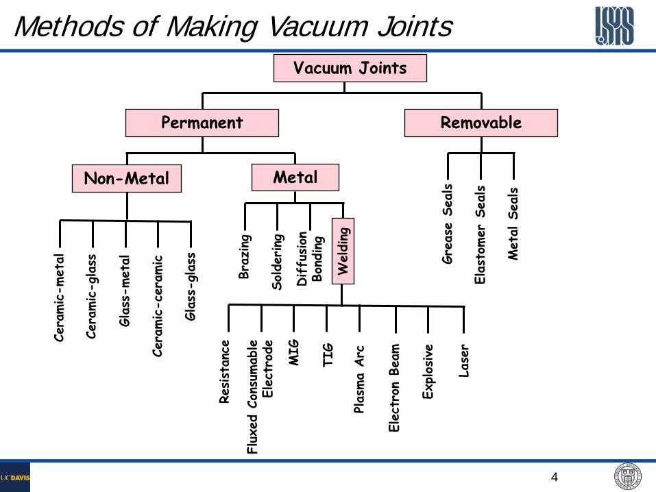
Methods of Making Vacuum Joints
Flux
ed C
onsu
mab
le
Elec
trod
e
Vacuum Joints
Permanent
Non-Metal Ce
ramic-c
eram
ic
Cera
mic-m
etal
Glas
s-glas
s
Glas
s-met
al
Cera
mic-g
lass
Metal
Braz
ing
Diffu
sion
Bo
nding
Solder
ing
Welding
TI
G
Resist
ance
Plas
ma
Arc
MIG
Elec
tron
Bea
m
Explos
ive
Lase
r Gr
ease
Sea
ls
Met
al S
eals
Elas
tomer
Sea
ls
Removable
5
Welding Welding is the process where two materials are joined by fusion
Welding is the most common method for joining metals in vacuum systems.
Inert gas welding is the most common type of welding (TIG, MIG).
Joint design is critical from vacuum, metallurgical and distortion standpoints.
Cleanliness is essential.
Other welding processes to consider are electron beam and laser welding.
6
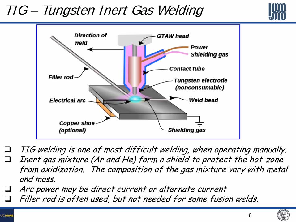
TIG – Tungsten Inert Gas Welding
TIG welding is one of most difficult welding, when operating manually. Inert gas mixture (Ar and He) form a shield to protect the hot-zone
from oxidization. The composition of the gas mixture vary with metal and mass.
Arc power may be direct current or alternate current Filler rod is often used, but not needed for some fusion welds.
7
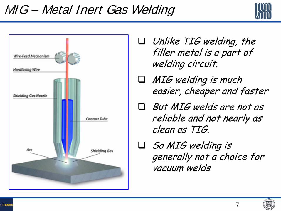
MIG – Metal Inert Gas Welding
Unlike TIG welding, the filler metal is a part of welding circuit.
MIG welding is much easier, cheaper and faster
But MIG welds are not as reliable and not nearly as clean as TIG.
So MIG welding is generally not a choice for vacuum welds
8
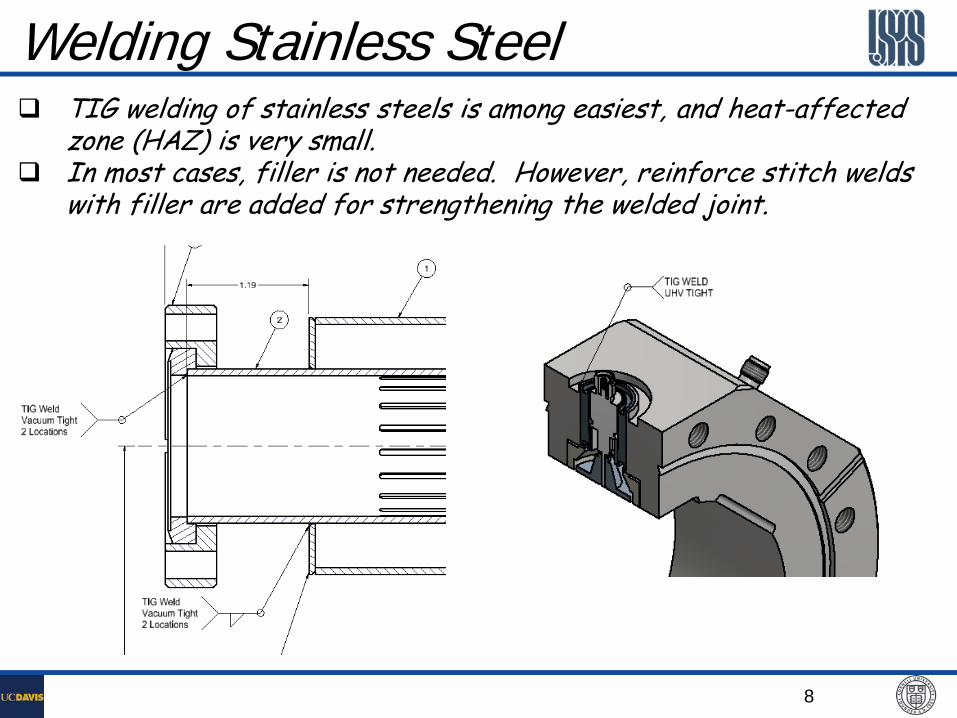
Welding Stainless Steel TIG welding of stainless steels is among easiest, and heat-affected
zone (HAZ) is very small. In most cases, filler is not needed. However, reinforce stitch welds
with filler are added for strengthening the welded joint.
9
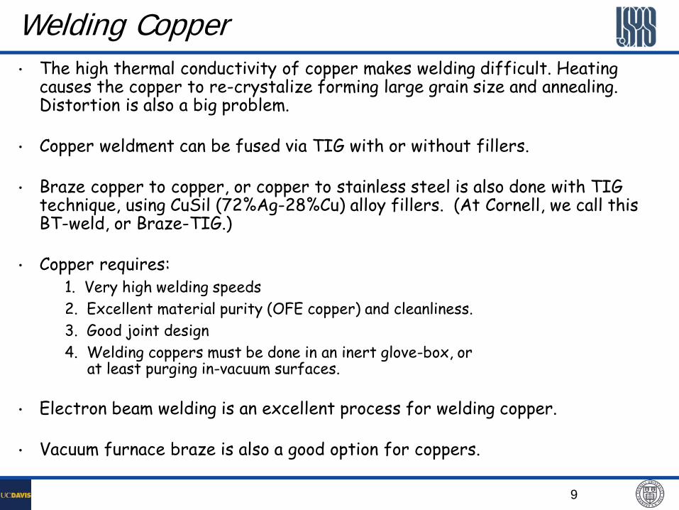
Welding Copper • The high thermal conductivity of copper makes welding difficult. Heating
causes the copper to re-crystalize forming large grain size and annealing. Distortion is also a big problem.
• Copper weldment can be fused via TIG with or without fillers.
• Braze copper to copper, or copper to stainless steel is also done with TIG technique, using CuSil (72%Ag-28%Cu) alloy fillers. (At Cornell, we call this BT-weld, or Braze-TIG.)
• Copper requires: 1. Very high welding speeds 2. Excellent material purity (OFE copper) and cleanliness. 3. Good joint design 4. Welding coppers must be done in an inert glove-box, or
at least purging in-vacuum surfaces.
• Electron beam welding is an excellent process for welding copper.
• Vacuum furnace braze is also a good option for coppers.

10
Welding Aluminum Low melting point, relatively high thermal conductivity, and high rate of
thermal expansion make welding aluminum more problematic than stainless steel.
Aluminum requires: High welding speeds (higher current densities) Good material purity and cleanliness Good joint design
Aluminum welds have a tendency to crack from excessive shrinkage stresses due to their high rate of thermal contraction. Filler rods (usually 4043 or similar alloys) always needed.
Due to relatively large weld-beads, out-side welding seams are very common for aluminum welds
To keep the aluminum weldment clean from oxidization, AC power is usually used during TIG, with characteristic popping noises.
11
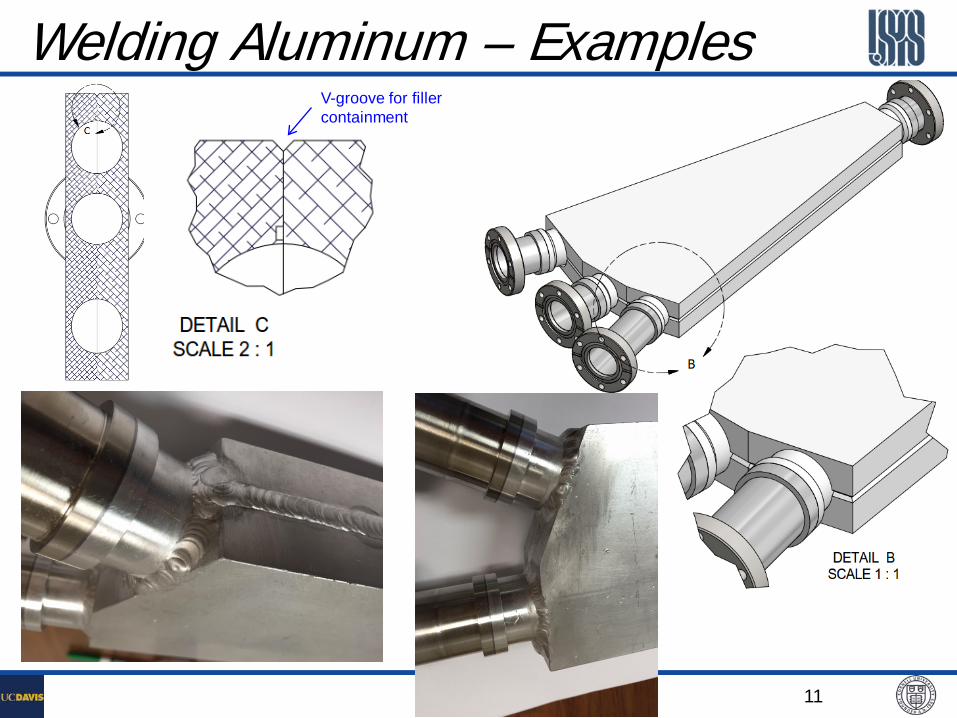
Welding Aluminum – Examples V-groove for filler containment
12
Electron Beam Welding (EBW) • EBW provides extremely high energy density in its focused
beam producing deep, narrow welds.
• This rapid welding process minimizes distortion and the heat affected zone.
• Very good control and reproducibility in weld penetration.
• A disadvantage of EBW is that the process takes place under vacuum (P = 10-5 Torr): — Extensive fixturing required — High initial cost — Weld preps are extremely critical, as no filler used. — Complexity — Welds are not cleanable

13
Copper chambers EBW
RF Cavity
Load into EBW Chamber E- beam welding
Welding 1-mm thick Copper Cover on CesrTA EC Detector Chamber
14
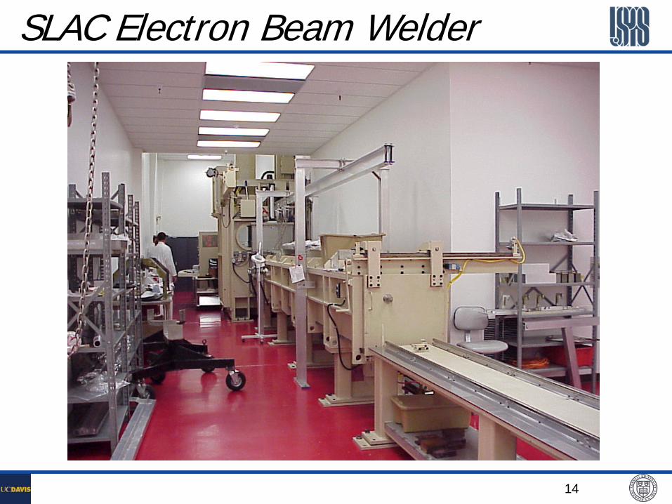
SLAC Electron Beam Welder
15
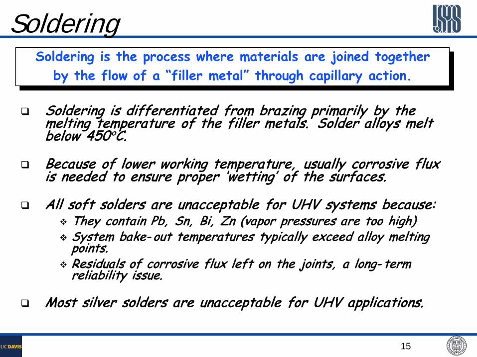
Soldering Soldering is the process where materials are joined together
by the flow of a “filler metal” through capillary action.
Soldering is differentiated from brazing primarily by the melting temperature of the filler metals. Solder alloys melt below 450°C.
Because of lower working temperature, usually corrosive flux is needed to ensure proper ‘wetting’ of the surfaces.
All soft solders are unacceptable for UHV systems because: They contain Pb, Sn, Bi, Zn (vapor pressures are too high) System bake- out temperatures typically exceed alloy melting
points. Residuals of corrosive flux left on the joints, a long- term
reliability issue.
Most silver solders are unacceptable for UHV applications.
16
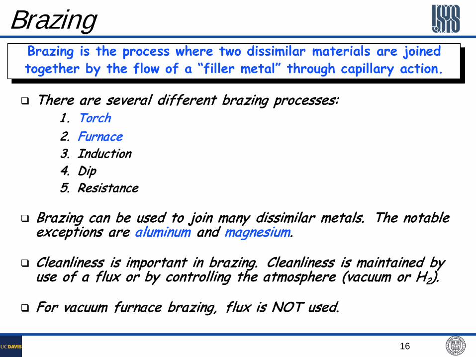
Brazing Brazing is the process where two dissimilar materials are joined together by the flow of a “filler metal” through capillary action.
There are several different brazing processes: 1 . Torch 2. Furnace 3. Induction 4. Dip 5. Resistance
Brazing can be used to join many dissimilar metals. The notable exceptions are aluminum and magnesium.
Cleanliness is important in brazing. Cleanliness is maintained by use of a flux or by controlling the atmosphere (vacuum or H2).
For vacuum furnace brazing, flux is NOT used.
17
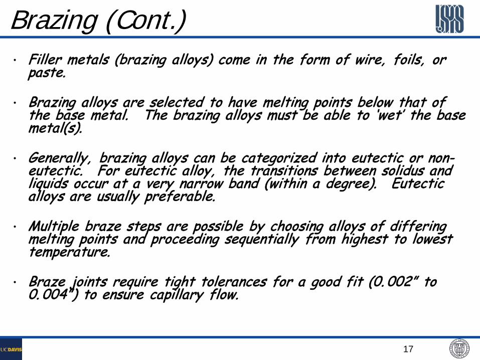
Brazing (Cont.) • Filler metals (brazing alloys) come in the form of wire, foils, or
paste.
• Brazing alloys are selected to have melting points below that of the base metal. The brazing alloys must be able to ‘wet’ the base metal(s).
• Generally, brazing alloys can be categorized into eutectic or non-eutectic. For eutectic alloy, the transitions between solidus and liquids occur at a very narrow band (within a degree). Eutectic alloys are usually preferable.
• Multiple braze steps are possible by choosing alloys of differing melting points and proceeding sequentially from highest to lowest temperature.
• Braze joints require tight tolerances for a good fit (0. 002” to 0. 004”) to ensure capillary flow.

18
Vacuum Braze Joints – Examples
CESR Beryllium Injection Windows
Post-brazing machining
720°C 980°C
19
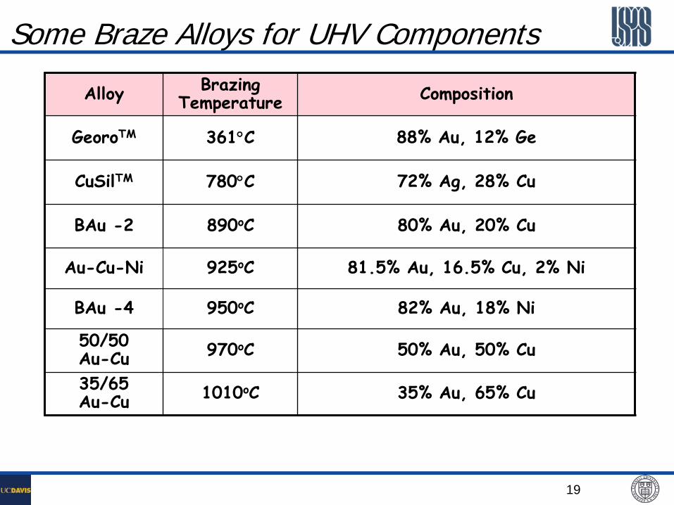
Some Braze Alloys for UHV Components
Alloy Brazing Temperature Composition
GeoroTM 361°C 88% Au, 12% Ge
CuSilTM 780°C 72% Ag, 28% Cu
BAu -2 890oC 80% Au, 20% Cu
Au-Cu-Ni 925oC 81.5% Au, 16.5% Cu, 2% Ni
BAu -4 950oC 82% Au, 18% Ni
50/50 Au-Cu 970oC 50% Au, 50% Cu
35/65 Au-Cu 1010oC 35% Au, 65% Cu

20
Permanent Joint Design Considerations Compatibility between materials to be jointed (welding,
brazing etc.)
Weld (joint) preps – Consult with your welder(s)
Seam accessibility – Consult with your welder(s)
Leak checking procedures and fixtures – Consult with your vacuum technicians
Weld fixability – Any joint may be leaky
All parts MUST be UHV cleaned before any welding
21
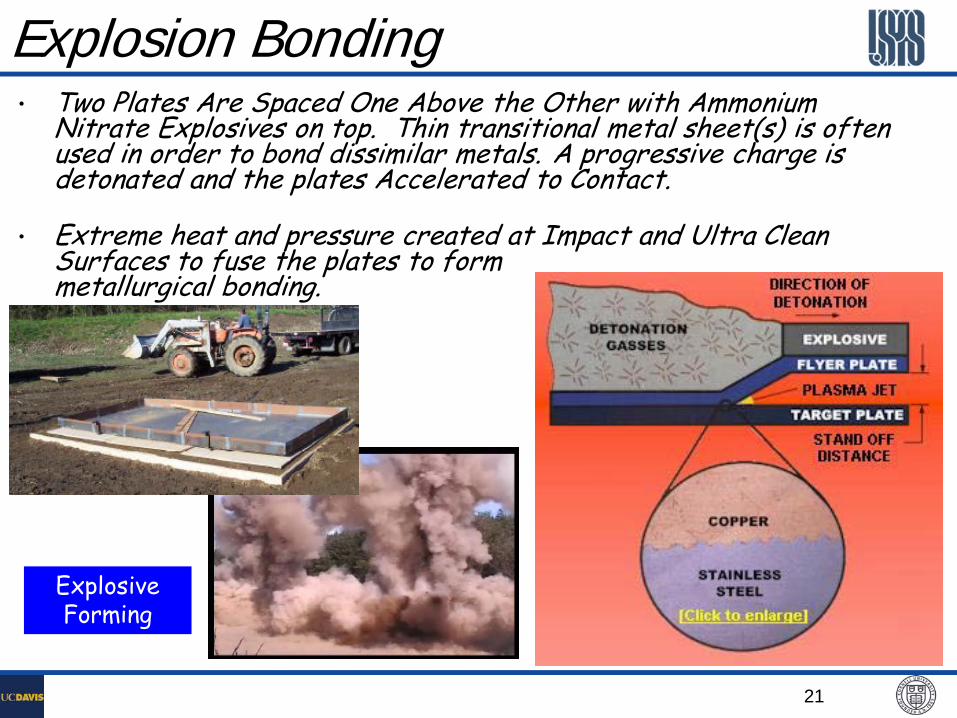
Explosion Bonding • Two Plates Are Spaced One Above the Other with Ammonium
Nitrate Explosives on top. Thin transitional metal sheet(s) is often used in order to bond dissimilar metals. A progressive charge is detonated and the plates Accelerated to Contact.
• Extreme heat and pressure created at Impact and Ultra Clean Surfaces to fuse the plates to form metallurgical bonding.
Explosive Forming
22
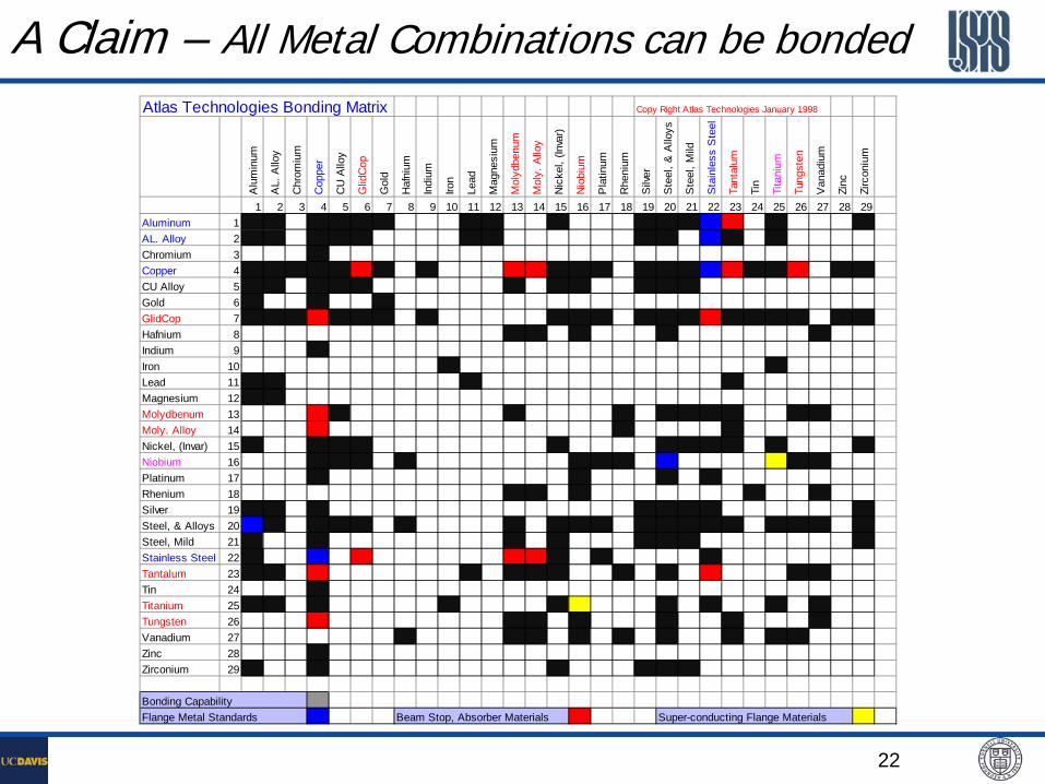
Atlas Technologies Bonding Matrix Copy Right Atlas Technologies January 1998
Alu
min
um
AL.
Allo
y
Chr
omiu
m
Cop
per
CU
Allo
y
Glid
Cop
Gol
d
Haf
nium
Indi
um
Iron
Lead
Mag
nesi
um
Mol
ydbe
num
Mol
y. A
lloy
Nic
kel,
(Inva
r)
Nio
bium
Pla
tinum
Rhe
nium
Silv
er
Ste
el, &
Allo
ys
Ste
el, M
ild
Sta
inle
ss S
teel
Tant
alum
Tin
Tita
nium
Tung
sten
Van
adiu
m
Zinc
Zirc
oniu
m
1 2 3 4 5 6 7 8 9 10 11 12 13 14 15 16 17 18 19 20 21 22 23 24 25 26 27 28 29Aluminum 1AL. Alloy 2Chromium 3Copper 4CU Alloy 5Gold 6GlidCop 7Hafnium 8Indium 9Iron 10Lead 11Magnesium 12Molydbenum 13Moly. Alloy 14Nickel, (Invar) 15Niobium 16Platinum 17Rhenium 18Silver 19Steel, & Alloys 20Steel, Mild 21Stainless Steel 22Tantalum 23Tin 24Titanium 25Tungsten 26Vanadium 27Zinc 28Zirconium 29
Bonding Capability Flange Metal Standards Beam Stop, Absorber Materials Super-conducting Flange Materials
A Claim – All Metal Combinations can be bonded
23
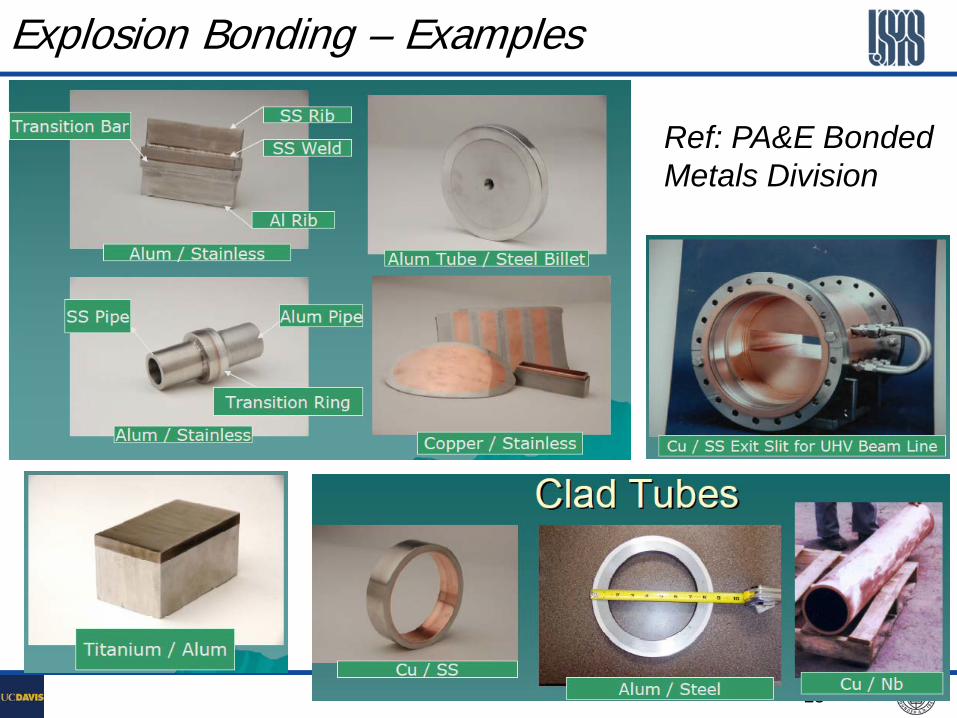
Explosion Bonding – Examples
Ref: PA&E Bonded Metals Division
24
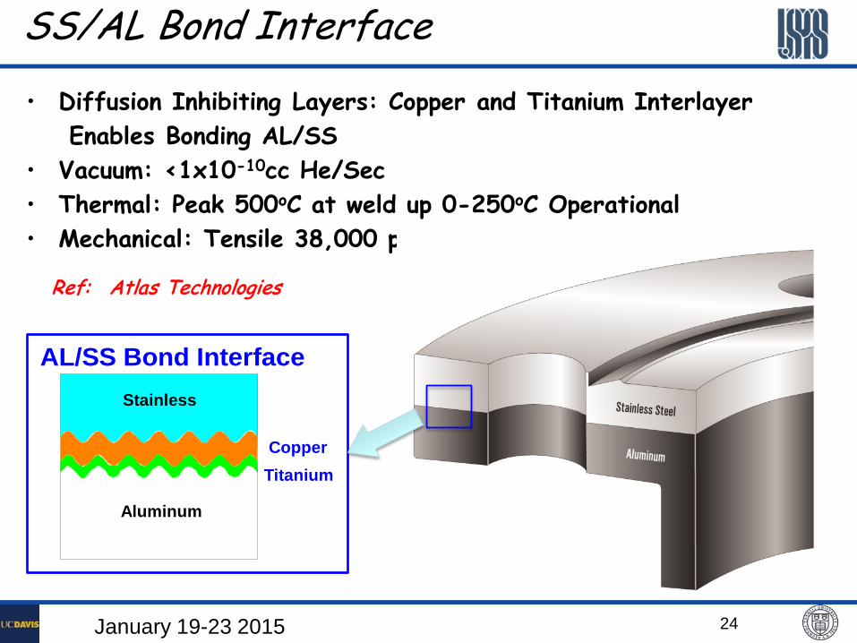
SS/AL Bond Interface
Stainless
Aluminum
Stainless
CopperTitanium
AL/SS Bond Interface
• Diffusion Inhibiting Layers: Copper and Titanium Interlayer Enables Bonding AL/SS
• Vacuum: <1x10⁻¹⁰cc He/Sec • Thermal: Peak 500oC at weld up 0-250oC Operational • Mechanical: Tensile 38,000 psi; Shear 30,000 psi
Ref: Atlas Technologies
January 19-23 2015
25
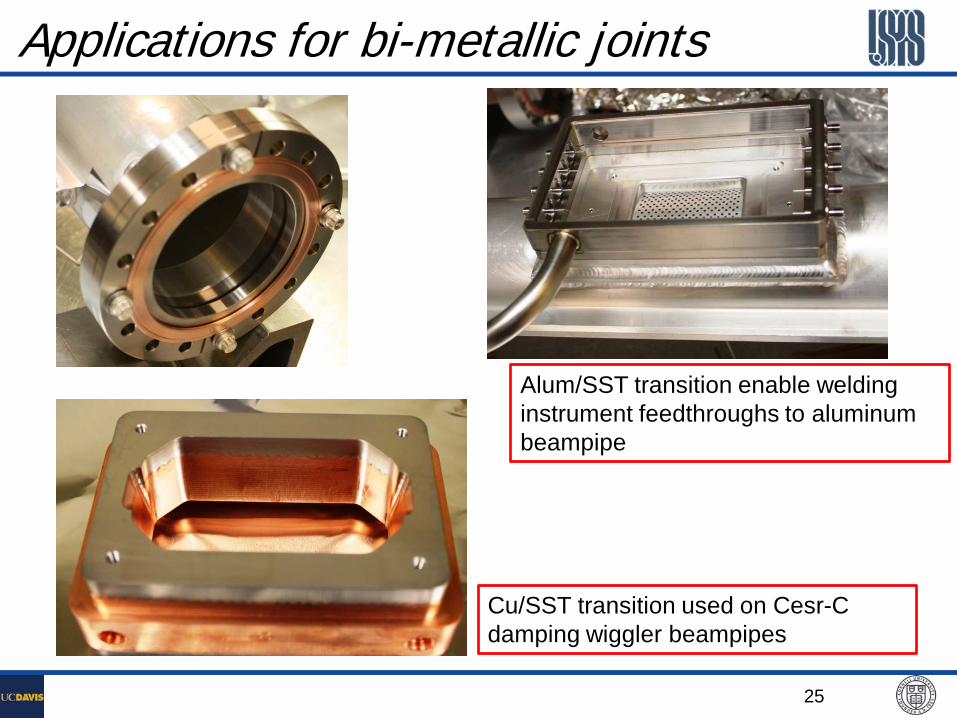
Applications for bi-metallic joints
Alum/SST transition enable welding instrument feedthroughs to aluminum beampipe
Cu/SST transition used on Cesr-C damping wiggler beampipes
26
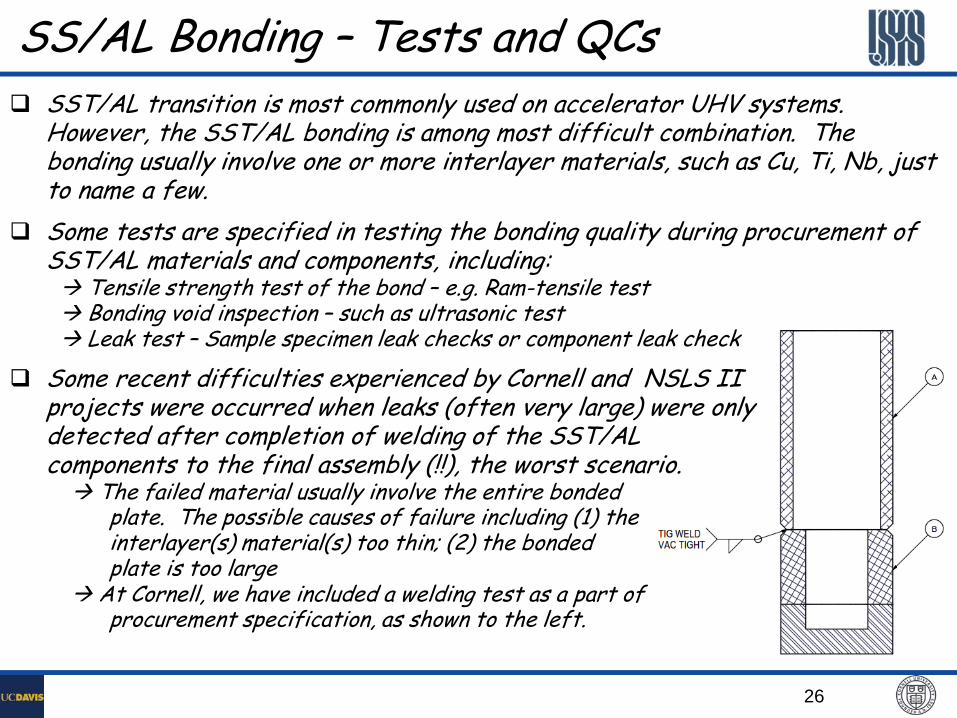
SS/AL Bonding – Tests and QCs SST/AL transition is most commonly used on accelerator UHV systems.
However, the SST/AL bonding is among most difficult combination. The bonding usually involve one or more interlayer materials, such as Cu, Ti, Nb, just to name a few.
Some tests are specified in testing the bonding quality during procurement of SST/AL materials and components, including:
Tensile strength test of the bond – e.g. Ram-tensile test Bonding void inspection – such as ultrasonic test Leak test – Sample specimen leak checks or component leak check
Some recent difficulties experienced by Cornell and NSLS II projects were occurred when leaks (often very large) were only detected after completion of welding of the SST/AL components to the final assembly (!!), the worst scenario. The failed material usually involve the entire bonded plate. The possible causes of failure including (1) the interlayer(s) material(s) too thin; (2) the bonded plate is too large At Cornell, we have included a welding test as a part of procurement specification, as shown to the left.
27
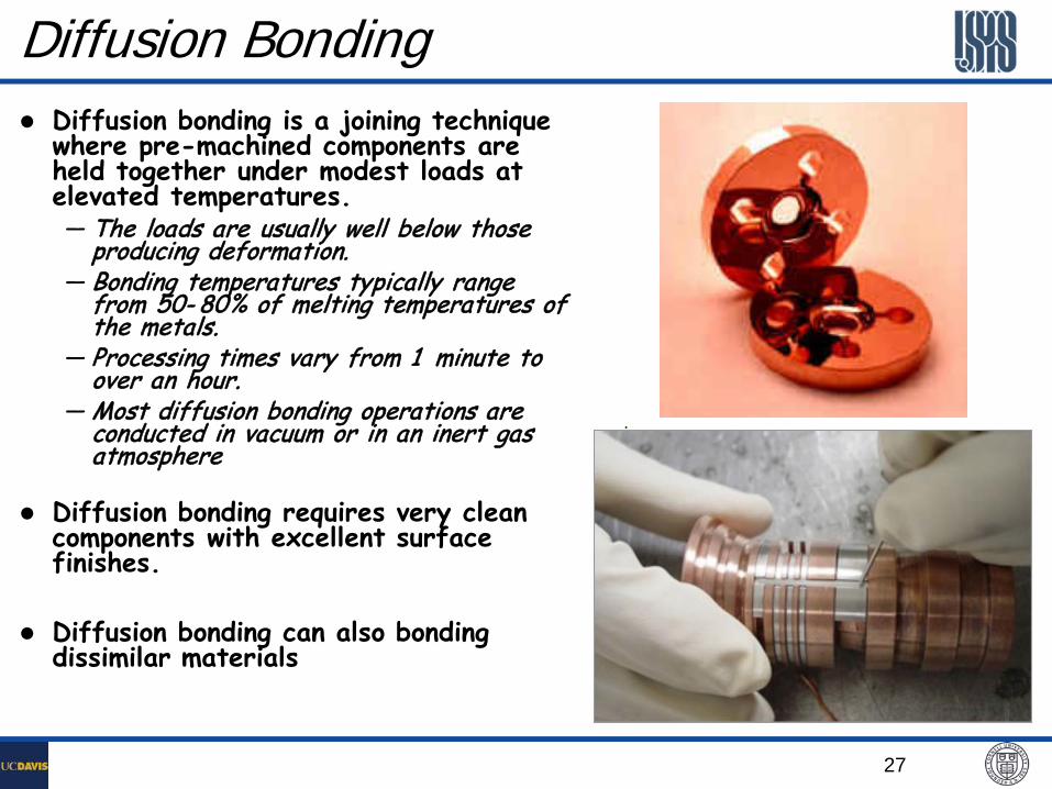
Diffusion bonding is a joining technique where pre-machined components are held together under modest loads at elevated temperatures. — The loads are usually well below those
producing deformation. — Bonding temperatures typically range
from 50- 80% of melting temperatures of the metals.
— Processing times vary from 1 minute to over an hour.
— Most diffusion bonding operations are conducted in vacuum or in an inert gas atmosphere
Diffusion bonding requires very clean components with excellent surface finishes.
Diffusion bonding can also bonding dissimilar materials
Diffusion Bonding
28
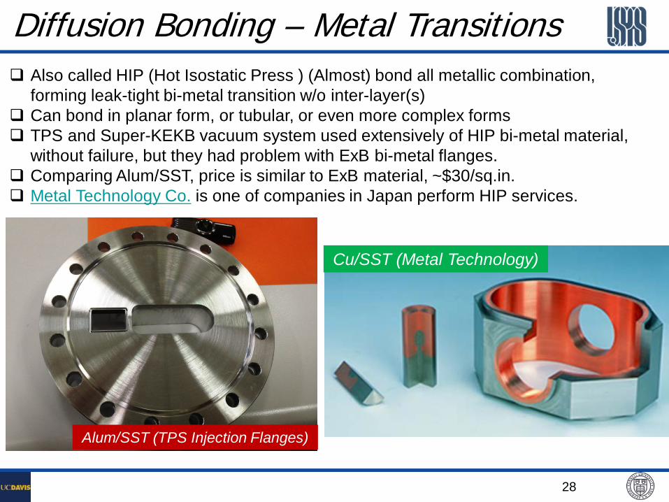
Diffusion Bonding – Metal Transitions Also called HIP (Hot Isostatic Press ) (Almost) bond all metallic combination,
forming leak-tight bi-metal transition w/o inter-layer(s) Can bond in planar form, or tubular, or even more complex forms TPS and Super-KEKB vacuum system used extensively of HIP bi-metal material,
without failure, but they had problem with ExB bi-metal flanges. Comparing Alum/SST, price is similar to ExB material, ~$30/sq.in. Metal Technology Co. is one of companies in Japan perform HIP services.
Alum/SST (TPS Injection Flanges)
Cu/SST (Metal Technology)
29
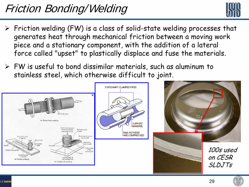
Friction Bonding/Welding
Friction welding (FW) is a class of solid-state welding processes that generates heat through mechanical friction between a moving work piece and a stationary component, with the addition of a lateral force called "upset" to plastically displace and fuse the materials.
FW is useful to bond dissimilar materials, such as aluminum to stainless steel, which otherwise difficult to joint.
100s used on CESR SLDJTs
30
Demountable Metal Sealed Joints
There are a variety of metal seals available for vacuum systems, including:
ConFlat flanges: for flanges OD <26”
Helicoflex seals: for customer designed flanges
Metal wire seal flanges: for large flanges
VATSEAL flanges: good RF properties
Metal seals are used for UHV systems, where permeation, as well as radiation damages, are not acceptable.
31
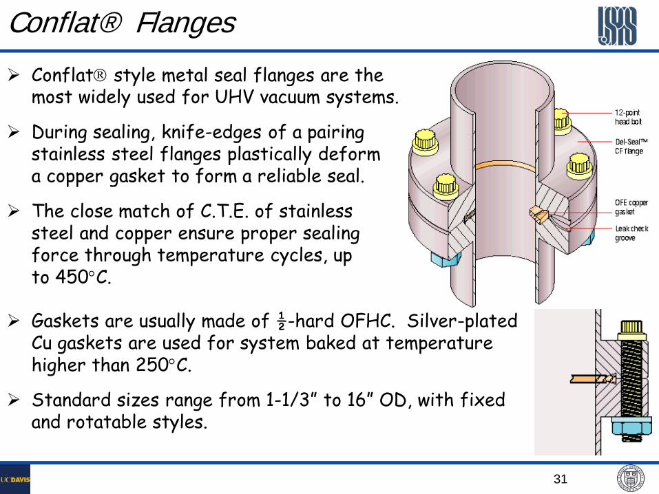
Conflat® Flanges
Conflat style metal seal flanges are the most widely used for UHV vacuum systems.
During sealing, knife-edges of a pairing stainless steel flanges plastically deform a copper gasket to form a reliable seal.
The close match of C.T.E. of stainless steel and copper ensure proper sealing force through temperature cycles, up to 450°C.
Gaskets are usually made of ½-hard OFHC. Silver-plated Cu gaskets are used for system baked at temperature higher than 250°C.
Standard sizes range from 1-1/3” to 16” OD, with fixed and rotatable styles.
32
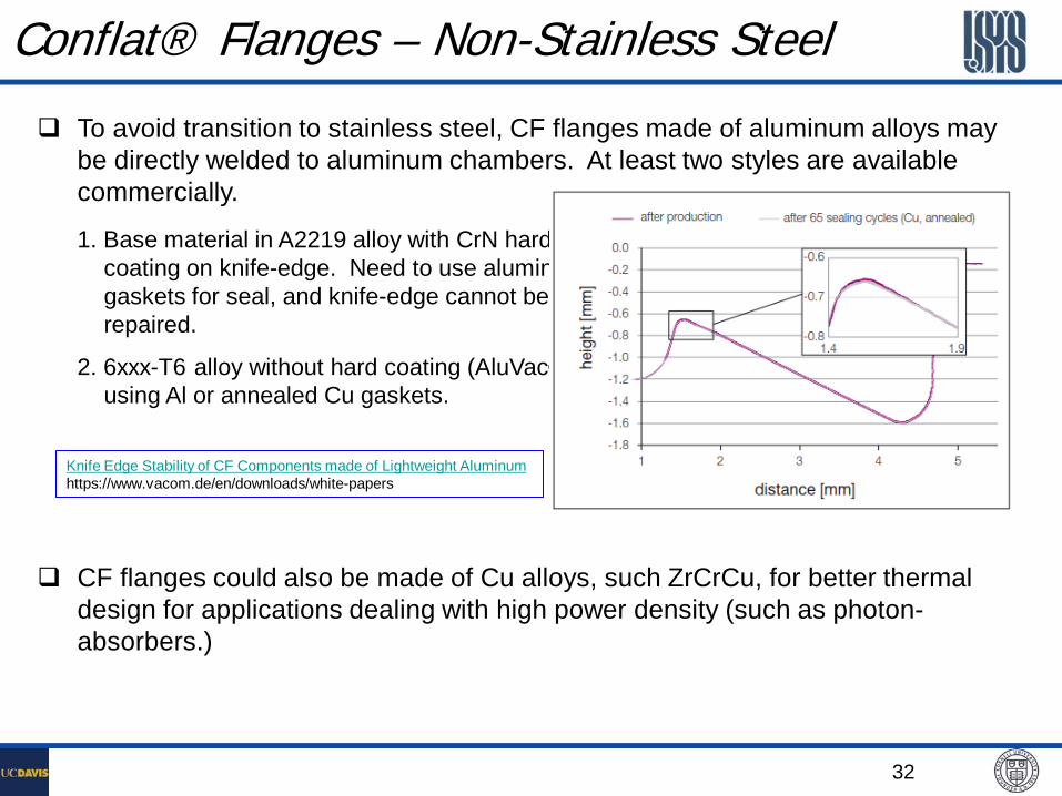
Conflat® Flanges – Non-Stainless Steel
To avoid transition to stainless steel, CF flanges made of aluminum alloys may be directly welded to aluminum chambers. At least two styles are available commercially.
1. Base material in A2219 alloy with CrN hardening coating on knife-edge. Need to use aluminum gaskets for seal, and knife-edge cannot be repaired.
2. 6xxx-T6 alloy without hard coating (AluVac), using Al or annealed Cu gaskets.
CF flanges could also be made of Cu alloys, such ZrCrCu, for better thermal design for applications dealing with high power density (such as photon-absorbers.)
Knife Edge Stability of CF Components made of Lightweight Aluminum https://www.vacom.de/en/downloads/white-papers
33
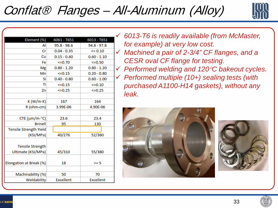
Conflat® Flanges – All-Aluminum (Alloy)
6013-T6 is readily available (from McMaster, for example) at very low cost.
Machined a pair of 2-3/4” CF flanges, and a CESR oval CF flange for testing.
Performed welding and 120°C bakeout cycles. Performed multiple (10+) sealing tests (with
purchased A1100-H14 gaskets), without any leak.

34
Conflat® Flanges Cont.
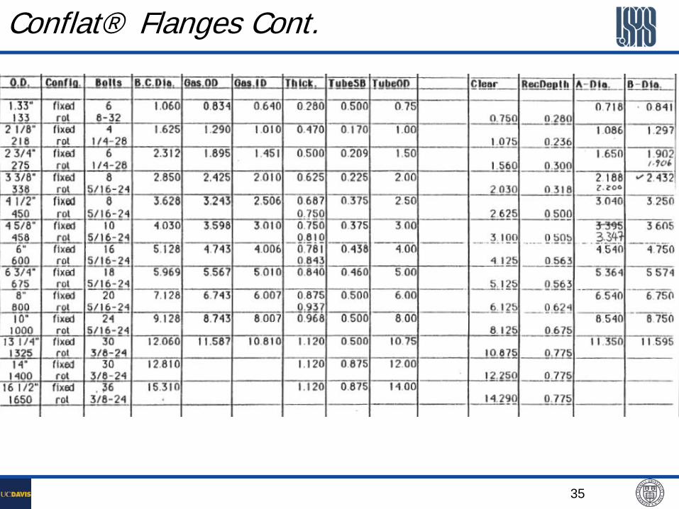
35
Conflat® Flanges Cont.
36
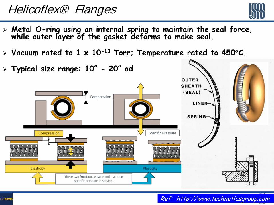
Helicoflex® Flanges Metal O-ring using an internal spring to maintain the seal force,
while outer layer of the gasket deforms to make seal.
Vacuum rated to 1 x 10-13 Torr; Temperature rated to 450°C.
Typical size range: 10” - 20” od
Ref: http://www.techneticsgroup.com
37
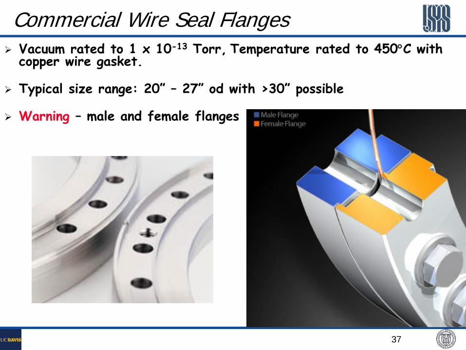
Commercial Wire Seal Flanges Vacuum rated to 1 x 10-13 Torr, Temperature rated to 450°C with
copper wire gasket.
Typical size range: 20” – 27” od with >30” possible
Warning – male and female flanges
38
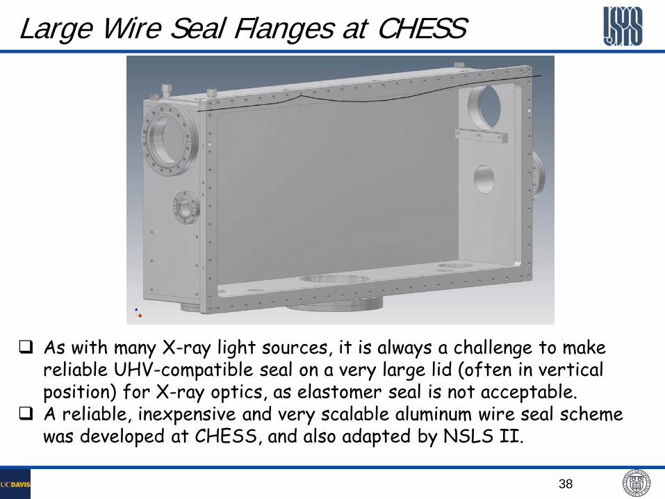
Large Wire Seal Flanges at CHESS
As with many X-ray light sources, it is always a challenge to make reliable UHV-compatible seal on a very large lid (often in vertical position) for X-ray optics, as elastomer seal is not acceptable.
A reliable, inexpensive and very scalable aluminum wire seal scheme was developed at CHESS, and also adapted by NSLS II.
39
1 1
2
2 3
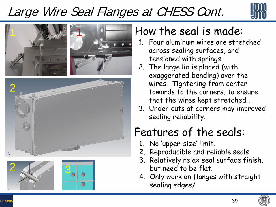
Large Wire Seal Flanges at CHESS Cont. How the seal is made: 1. Four aluminum wires are stretched
across sealing surfaces, and tensioned with springs.
2. The large lid is placed (with exaggerated bending) over the wires. Tightening from center towards to the corners, to ensure that the wires kept stretched .
3. Under cuts at corners may improved sealing reliability.
Features of the seals: 1. No ‘upper-size’ limit. 2. Reproducible and reliable seals 3. Relatively relax seal surface finish,
but need to be flat. 4. Only work on flanges with straight
sealing edges/

40
VATSEAL® Flanges A style of metal seal for vacuum, cryogenics and high
temperature applications.
silver-plated or gold-plated copper gaskets
VATSEAL metal seals make a leak-tight seal and at the same time a reliable, low resistance RF contact
41
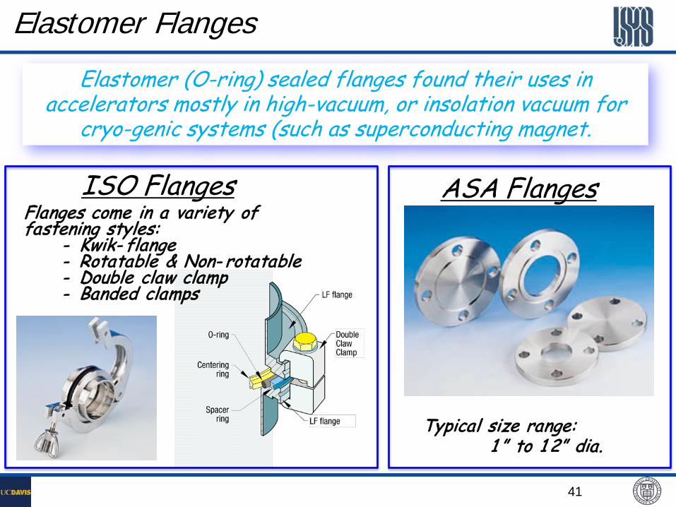
Elastomer Flanges
Elastomer (O-ring) sealed flanges found their uses in accelerators mostly in high-vacuum, or insolation vacuum for
cryo-genic systems (such as superconducting magnet.
ISO Flanges ASA Flanges Flanges come in a variety of fastening styles: - Kwik- flange - Rotatable & Non- rotatable - Double claw clamp - Banded clamps
Typical size range: 1 ” to 1 2” dia.
42
Elastomer Seals for UHV Systems
In general, elastomer seals are not suitable for accelerator UHV systems for the following reasons: Permeation through O-ring seals can be significant in humid environment (‘seasonal-effect’ was very visible at CESR in early days, with our old home-made GVs using O-ring bonnet seals. Radiation hardening of elastomer seals will result in leaks.
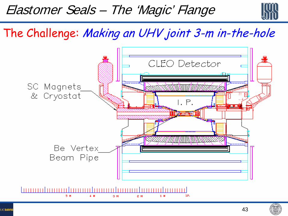
However, elastomer seals have been used with successes, in following CESR examples: Use O-ring as gate through seals for CESR’s RF-shielded gate valves with oval beam apertures. ~30 GVs in use in CESR for more than 20 years, no O-ring leak due to radiation hardening. This resulted in a very significant saving as compared to all-metal special RF-shielded GVs. Differentially pumped O-ring seals for (decommissioned) CLEO beryllium beampipe remote flange joints, aka the ‘magic’ flanges.
43
Elastomer Seals – The ‘Magic’ Flange
The Challenge: Making an UHV joint 3-m in-the-hole
44
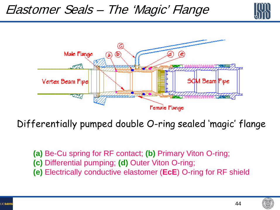
Elastomer Seals – The ‘Magic’ Flange
Differentially pumped double O-ring sealed ‘magic’ flange
(a) Be-Cu spring for RF contact; (b) Primary Viton O-ring; (c) Differential pumping; (d) Outer Viton O-ring; (e) Electrically conductive elastomer (EcE) O-ring for RF shield


