Vacuum Filter for Various Vacuum Piping Vacuum Filter Series · Vacuum Accessories Series Vacuum...
28
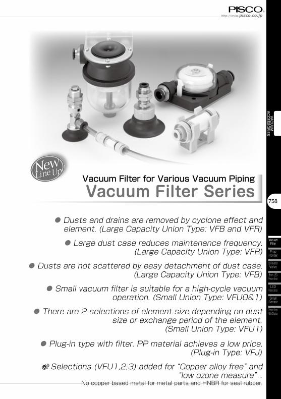
758 Vacuum Filter Free Holder Fall Prevention Valve Small Sensor Pressure Sensor With Display LED Pressure Sensor 8mm LED Pressure Sensor VACUUM ACCESSORIES Vacuum Filter for Various Vacuum Piping Vacuum Filter Series ● Dusts and drains are removed by cyclone effect and element. (Large Capacity Union Type: VFB and VFR) ● Large dust case reduces maintenance frequency. (Large Capacity Union Type: VFR) ● Dusts are not scattered by easy detachment of dust case. (Large Capacity Union Type: VFB) ● Small vacuum filter is suitable for a high-cycle vacuum operation. (Small Union Type: VFU0&1) ● There are 2 selections of element size depending on dust size or exchange period of the element. (Small Union Type: VFU1) ● Plug-in type with filter. PP material achieves a low price. (Plug-in Type: VFJ) Selections (VFU1,2,3) added for “Copper alloy free” and “low ozone measure” . No copper based metal for metal parts and HNBR for seal rubber.
Transcript of Vacuum Filter for Various Vacuum Piping Vacuum Filter Series · Vacuum Accessories Series Vacuum...
758
Vacuum Filter
Free Holder
Fall Prevention Valve
Small Sensor
Pressure Sensor With Display
LED Pressure Sensor
8mm LED Pressure Sensor
VACUUMACCESSO
RIES
Vacuum Filter for Various Vacuum Piping
Vacuum Filter Series● Dusts and drains are removed by cyclone effect and
element. (Large Capacity Union Type: VFB and VFR)● Large dust case reduces maintenance frequency.
(Large Capacity Union Type: VFR)● Dusts are not scattered by easy detachment of dust case.
(Large Capacity Union Type: VFB)● Small vacuum filter is suitable for a high-cycle vacuum
operation. (Small Union Type: VFU0&1)● There are 2 selections of element size depending on dust
size or exchange period of the element. (Small Union Type: VFU1)
● Plug-in type with filter. PP material achieves a low price. (Plug-in Type: VFJ)
Selections (VFU1,2,3) added for “Copper alloy free” and “low ozone measure” .
No copper based metal for metal parts and HNBR for seal rubber.
Vacuum Accessories SeriesVacuum Filter Series
759
Vacuum Filter
Add-on Blow-off Controller
Small Vacuum Regulator
VACU
UMAC
CESS
ORI
ESVA
CU
UM
G
ENER
ATO
REX
TERN
AL VA
CUUM
CO
NTRO
LLER
VAC
UU
MPA
D
BVF 6
① Type
② Filter size
Vacuum Filter
③IN-side tube dia.
①Type
20
②Filter size
6
④OUT-side tube dia.
W
⑤Color
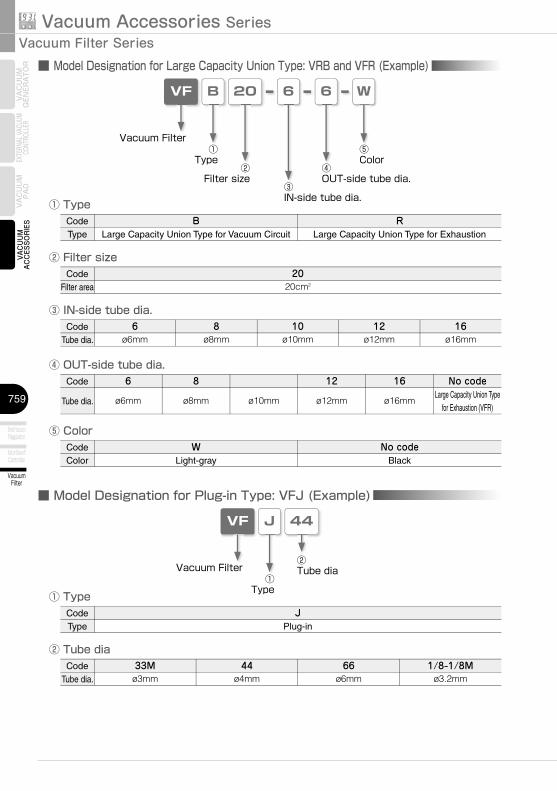
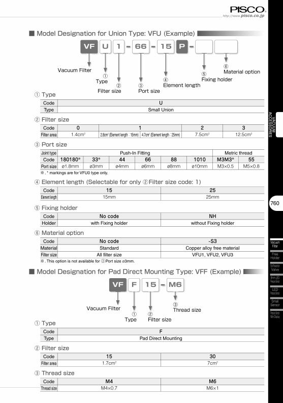
■ Model Designation for Large Capacity Union Type: VRB and VFR (Example)
③ IN-side tube dia.
④ OUT-side tube dia.
⑤ Color
JVF
① Type
Vacuum Filter①
Type
44
②Tube dia
■ Model Designation for Plug-in Type: VFJ (Example)
② Tube dia
CodeType
BLarge Capacity Union Type for Vacuum Circuit
CodeFilter area
2020cm2
RLarge Capacity Union Type for Exhaustion
CodeTube dia.
6ø6mm
8ø8mm
10ø10mm
12ø12mm
16ø16mm
Code
Tube dia.
6
ø6mm
8
ø8mm ø10mm
12
ø12mm
16
ø16mm
No codeLarge Capacity Union Type
for Exhaustion (VFR)
CodeColor
WLight-gray
No codeBlack
CodeType
JPlug-in
CodeTube dia.
33Mø3mm
66ø6mm
44ø4mm
1/8-1/8Mø3.2mm
760
Vacuum Filter
Free Holder
Fall Prevention Valve
Small Sensor
Pressure Sensor With Display
LED Pressure Sensor
8mm LED Pressure Sensor
VACUUMACCESSO
RIES
UVF 66
① Type
② Filter size
Vacuum Filter
③Port size
①Type
1
②Filter size
15
④Element length
P
■ Model Designation for Union Type: VFU (Example)
③ Port size
④ Element length (Selectable for only ②Filter size code: 1)
FVF M6
① Type
② Filter size
Vacuum Filter③Thread size
①Type
15
②Filter size
■ Model Designation for Pad Direct Mounting Type: VFF (Example)
③ Thread size
⑥Material option⑤
Fixing holder
⑤ Fixing holder
CodeType
USmall Union
CodeFilter area
1
Joint typeCode
Port size180180*ø1.8mm
CodeElement length
1515mm
27.5cm2
312.5cm22.8cm2 (Element length:15mm) 4.7cm2 (Element length:25mm)
Push-In Fitting Metric thread
2525mm
CodeType
FPad Direct Mounting
CodeFilter area
CodeThread size
M4M4×0.7
151.7cm2
307cm2
M6M6×1
01.4cm2
⑥ Material optionCode
MaterialFilter size
No code -S3Standard
All filter sizeCopper alloy free material
VFU1, VFU2, VFU3
33*ø3mm
44ø4mm
66ø6mm
88ø8mm
1010ø10mm
M3M3*M3×0.5
55M5×0.8
※ . * markings are for VFU0 type only.
CodeHolder
No codewith Fixing holder
NHwithout Fixing holder
※ . This option is not available for ③Port size ø3mm.
Vacuum Accessories SeriesVacuum Filter Series
761
Vacuum Filter
Add-on Blow-off Controller
Small Vacuum Regulator
VACU
UMAC
CESS
ORI
ESVA
CU
UM
G
ENER
ATO
REX
TERN
AL VA
CUUM
CO
NTRO
LLER
VAC
UU
MPA
D
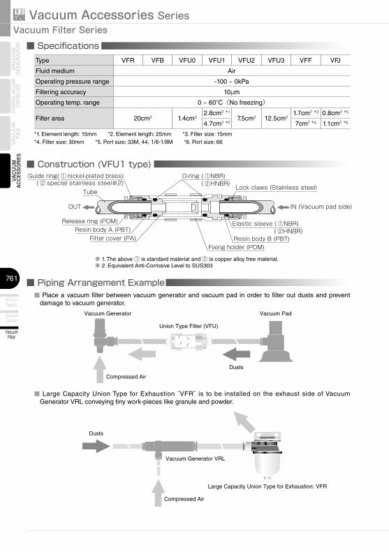
■ Specifications
Union Type Filter (VFU)
Vacuum Pad
Compressed Air
Vacuum Generator
Dusts
■ Piping Arrangement Example
Vacuum Generator VRL
Compressed Air
Large Capacity Union Type for Exhaustion: VFR
Dusts
■ Construction (VFU1 type)
Elastic sleeve ( ①NBR)
Tube
Release ring (POM)
Guide ring( ① nickel-plated brass)( ② special stainless steel※2)
Resin body A (PBT)Resin body B (PBT)Filter cover (PA)
Fixing holder (POM)
O-ring ( ①NBR)
( ②HNBR)
( ②HNBR) Lock claws (Stainless steel)
OUT IN (Vacuum pad side)
※ 1. The above ① is standard material and ② is copper alloy free material.※ 2. Equivalent Anti-Corrosive Level to SUS303
Type VFR VFB VFU0 VFU1 VFU2 VFU3 VFF VFJ
Fluid medium Air
Operating pressure range -100 ~ 0kPa
Filtering accuracy 10µm
Operating temp. range 0 ~ 60ºC(No freezing)
Filter area 20cm² 1.4cm²2.8cm² *¹
7.5cm² 12.5cm²1.7cm² *³ 0.8cm² *5
4.7cm² *² 7cm² *4 1.1cm² *6
■ Place a vacuum filter between vacuum generator and vacuum pad in order to filter out dusts and prevent damage to vacuum generator.
■ Large Capacity Union Type for Exhaustion “VFR” is to be installed on the exhaust side of Vacuum Generator VRL conveying tiny work-pieces like granule and powder.
*1. Element length: 15mm *2. Element length: 25mm *3. Filter size: 15mm*4. Filter size: 30mm *5. Port size: 33M, 44, 1/8-1/8M *6. Port size: 66
762
Vacuum Filter
Free Holder
Fall Prevention Valve
Small Sensor
Pressure Sensor With Display
LED Pressure Sensor
8mm LED Pressure Sensor
VACUUMACCESSO
RIES
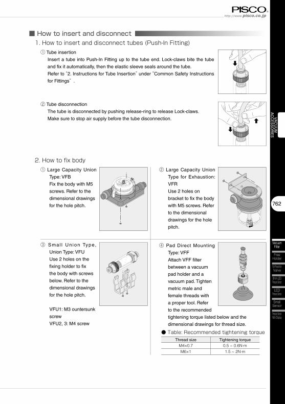
■ How to insert and disconnect1. How to insert and disconnect tubes (Push-In Fitting)
① Tube insertion
Insert a tube into Push-In Fitting up to the tube end. Lock-claws bite the tube
and fix it automatically, then the elastic sleeve seals around the tube.
Refer to “2. Instructions for Tube Insertion” under “Common Safety Instructions
for Fittings” .
② Tube disconnection
The tube is disconnected by pushing release-ring to release Lock-claws.
Make sure to stop air supply before the tube disconnection.
2. How to fix body① Large Capacity Union
Type: VFB
Fix the body with M5
screws. Refer to the
dimensional drawings
for the hole pitch.
② Large Capacity Union
Type for Exhaustion:
VFR
Use 2 holes on
bracket to fix the body
with M5 screws. Refer
to the dimensional
drawings for the hole
pitch.
③ Sma l l Un ion Type,
Union Type: VFU
Use 2 holes on the
fixing holder to fix
the body with screws
below. Refer to the
dimensional drawings
for the hole pitch.
VFU1: M3 ountersunk
screw
VFU2, 3: M4 screw
④ Pad Direct Mounting
Type: VFF
Attach VFF filter
between a vacuum
pad holder and a
vacuum pad. Tighten
metric male and
female threads with
a proper tool. Refer
to the recommended
tightening torque listed below and the
dimensional drawings for thread size.
● Table: Recommended tightening torqueThread size Tightening torque
M4×0.7 0.5 ~ 0.6N·mM6×1 1.5 ~ 2N·m
Vacuum Accessories SeriesVacuum Filter Series
763
Vacuum Filter
Add-on Blow-off Controller
Small Vacuum Regulator
VACU
UMAC
CESS
ORI
ESVA
CU
UM
G
ENER
ATO
REX
TERN
AL VA
CUUM
CO
NTRO
LLER
VAC
UU
MPA
D
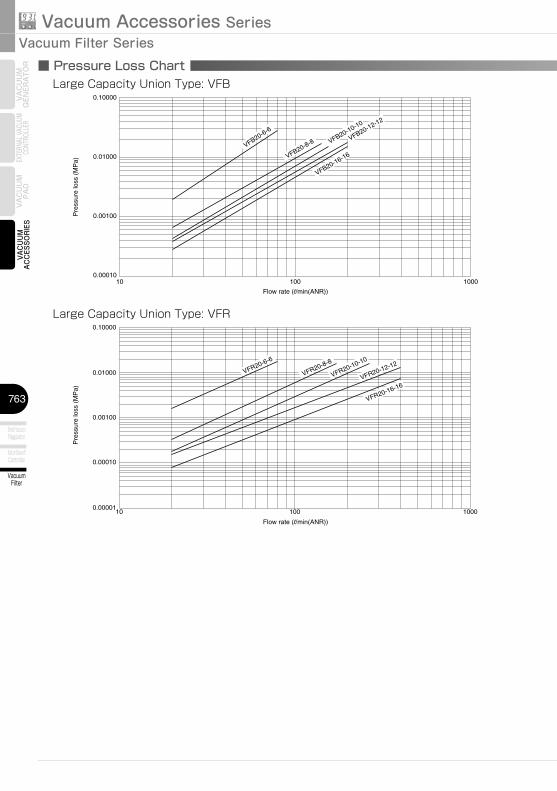
10 100 10000.00010
0.00100
0.01000
0.10000
Pre
ssur
e lo
ss (
MP
a)
Flow rate (l/min(ANR))
VFB20-6-6
VFB20-8-8 VFB20-10-10
VFB20-12-12
VFB20-16-16
■ Pressure Loss Chart
10 100 1000
0.00010
0.00001
0.00100
0.01000
0.10000
Pre
ssur
e lo
ss (
MP
a)
Flow rate (l/min(ANR))
VFR20-6-6
VFR20-8-8
VFR20-10-10
VFR20-12-12
VFR20-16-16
Large Capacity Union Type: VFB
Large Capacity Union Type: VFR
764
Vacuum Filter
Free Holder
Fall Prevention Valve
Small Sensor
Pressure Sensor With Display
LED Pressure Sensor
8mm LED Pressure Sensor
VACUUMACCESSO
RIES
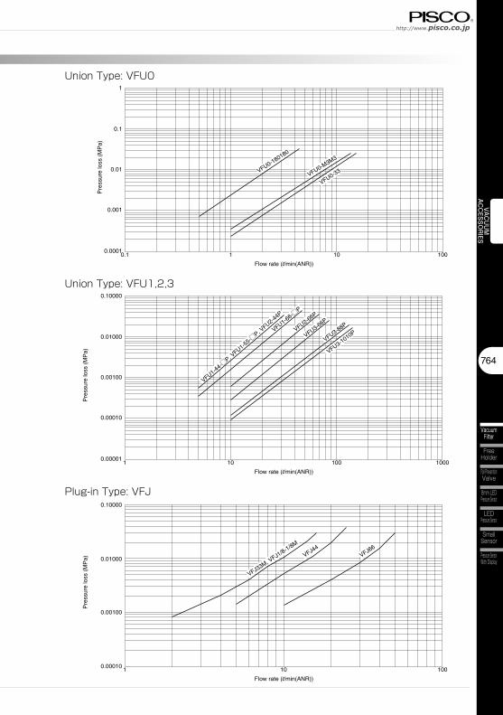
0.1 101 100
0.001
0.0001
0.01
0.1
1
Pre
ssur
e lo
ss (
MP
a)
Flow rate (l/min(ANR))
VFU0-180180
VFU0-M3M3
VFU0-33
1 10 1000.00010
0.00100
0.01000
0.10000
Pre
ssur
e lo
ss (
MP
a)
Flow rate (l/min(ANR))
VFJ44
VFJ33M, V
FJ1/8-1/8M
VFJ66
1 10010 1000
0.00010
0.00001
0.00100
0.01000
0.10000
Pre
ssur
e lo
ss (
MP
a)
Flow rate (l/min(ANR))
VFU1-44-□
P, VFU1-5
5-□P, V
FU2-44P
VFU3-88P
VFU3-66PVFU2-66P
VFU1-66-□P
VFU3-1010P
Union Type: VFU0
Plug-in Type: VFJ
Union Type: VFU1,2,3
Vacuum Accessories SeriesVacuum Filter Series
765
Vacuum Filter
Add-on Blow-off Controller
Small Vacuum Regulator
VACU
UMAC
CESS
ORI
ESVA
CU
UM
G
ENER
ATO
REX
TERN
AL VA
CUUM
CO
NTRO
LLER
VAC
UU
MPA
D
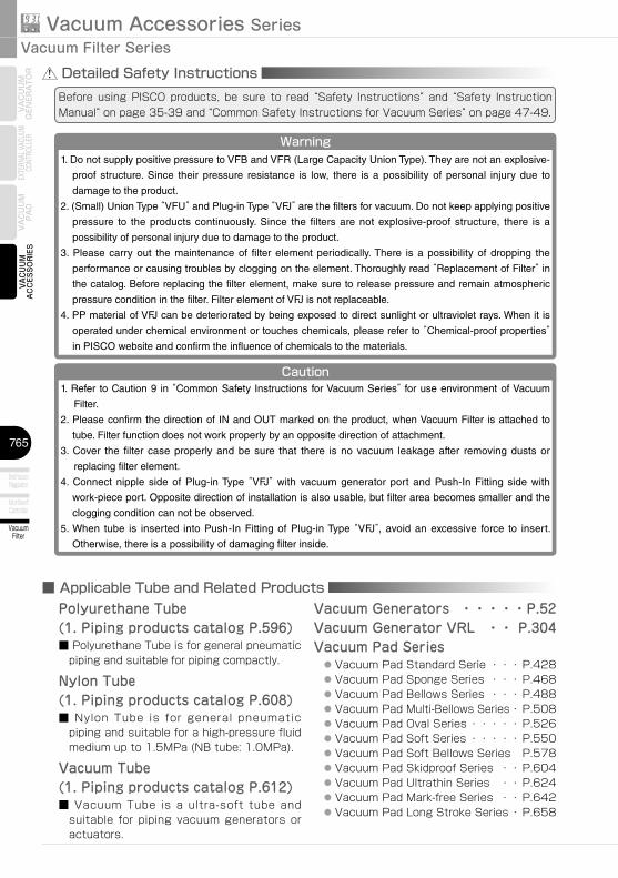
Detailed Safety InstructionsBefore using PISCO products, be sure to read “Safety Instructions” and “Safety Instruction Manual” on page 35-39 and “Common Safety Instructions for Vacuum Series” on page 47-49.
Warning1. Do not supply positive pressure to VFB and VFR (Large Capacity Union Type). They are not an explosive-
proof structure. Since their pressure resistance is low, there is a possibility of personal injury due to
damage to the product.
2. (Small) Union Type “VFU” and Plug-in Type “VFJ” are the filters for vacuum. Do not keep applying positive
pressure to the products continuously. Since the filters are not explosive-proof structure, there is a
possibility of personal injury due to damage to the product.
3. Please carry out the maintenance of filter element periodically. There is a possibility of dropping the
performance or causing troubles by clogging on the element. Thoroughly read “Replacement of Filter” in
the catalog. Before replacing the filter element, make sure to release pressure and remain atmospheric
pressure condition in the filter. Filter element of VFJ is not replaceable.
4. PP material of VFJ can be deteriorated by being exposed to direct sunlight or ultraviolet rays. When it is
operated under chemical environment or touches chemicals, please refer to “Chemical-proof properties” in PISCO website and confirm the influence of chemicals to the materials.
Caution1. Refer to Caution 9 in “Common Safety Instructions for Vacuum Series” for use environment of Vacuum
Filter.
2. Please confirm the direction of IN and OUT marked on the product, when Vacuum Filter is attached to
tube. Filter function does not work properly by an opposite direction of attachment.
3. Cover the filter case properly and be sure that there is no vacuum leakage after removing dusts or
replacing filter element.
4. Connect nipple side of Plug-in Type “VFJ” with vacuum generator port and Push-In Fitting side with
work-piece port. Opposite direction of installation is also usable, but filter area becomes smaller and the
clogging condition can not be observed.
5. When tube is inserted into Push-In Fitting of Plug-in Type “VFJ”, avoid an excessive force to insert.
Otherwise, there is a possibility of damaging filter inside.
■ Applicable Tube and Related ProductsPolyurethane Tube(1. Piping products catalog P.596)■ Polyurethane Tube is for general pneumatic
piping and suitable for piping compactly.
Nylon Tube(1. Piping products catalog P.608)■ Nylon Tube is for general pneumatic
piping and suitable for a high-pressure fluid medium up to 1.5MPa (NB tube: 1.0MPa).
Vacuum Tube(1. Piping products catalog P.612)■ Vacuum Tube is a ultra-soft tube and
suitable for piping vacuum generators or actuators.
Vacuum Generators ・・・・・P.52Vacuum Generator VRL ・・ P.304Vacuum Pad Series ● Vacuum Pad Standard Serie ・・・ P.428 ● Vacuum Pad Sponge Series ・・・ P.468 ● Vacuum Pad Bellows Series ・・・ P.488 ● Vacuum Pad Multi-Bellows Series ・ P.508 ● Vacuum Pad Oval Series ・・・・・ P.526 ● Vacuum Pad Soft Series ・・・・・ P.550 ● Vacuum Pad Soft Bellows Series P.578 ● Vacuum Pad Skidproof Series ・・ P.604 ● Vacuum Pad Ultrathin Series ・・ P.624 ● Vacuum Pad Mark-free Series ・・ P.642 ● Vacuum Pad Long Stroke Series ・ P.658
766
Vacuum Filter
Free Holder
Fall Prevention Valve
Small Sensor
Pressure Sensor With Display
LED Pressure Sensor
8mm LED Pressure Sensor
VACUUMACCESSO
RIES
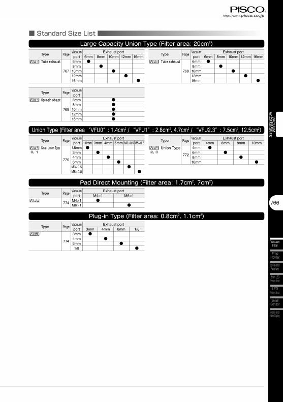
■ Standard Size ListLarge Capacity Union Type (Filter area: 20cm2)
VFB VFR
VFR Open-air exhaust
Tube exhaust Tube exhaust
Union Type (Filter area “VFU0”: 1.4cm2 / “VFU1”: 2.8cm2, 4.7cm2 / “VFU2,3”: 7.5cm2, 12.5cm2)
VFU VFUSmall Union Type Union Type
Pad Direct Mounting (Filter area: 1.7cm2, 7cm2)
VFF
Plug-in Type (Filter area: 0.8cm2, 1.1cm2)
VFJ
0, 1 2, 3
Type PageVacuumport
Exhaust port6mm 8mm 10mm 12mm 16mm
767
6mm8mm10mm12mm16mm
●●
●●
●
Type PageVacuumport
Exhaust port6mm 8mm 10mm 12mm 16mm
768
6mm8mm10mm12mm16mm
●●
●●
●
Type PageVacuumport
768
6mm8mm10mm12mm16mm
●●●●●
Type PageVacuumport
Exhaust port1.8mm
770
1.8mm3mm4mm6mm
M3×0.5M5×0.8
●
Type PageVacuumport
Exhaust port4mm
772
4mm6mm8mm10mm
●M3×0.5 6mm
●
8mm
●
10mm
●
Type PageVacuumport
Exhaust portM4×1
774M4×1M6×1
●M6×1
●
Type PageVacuumport
Exhaust port3mm
774
3mm4mm6mm1/8
●6mm
●
4mm
●
1/8
●
●●
●●
●
M5×0.83mm 4mm 6mm
Vacuum Accessories SeriesVacuum Filter Series
767
Vacuum Filter
Add-on Blow-off Controller
Small Vacuum Regulator
VACU
UMAC
CESS
ORI
ESVA
CU
UM
G
ENER
ATO
REX
TERN
AL VA
CUUM
CO
NTRO
LLER
VAC
UU
MPA
D
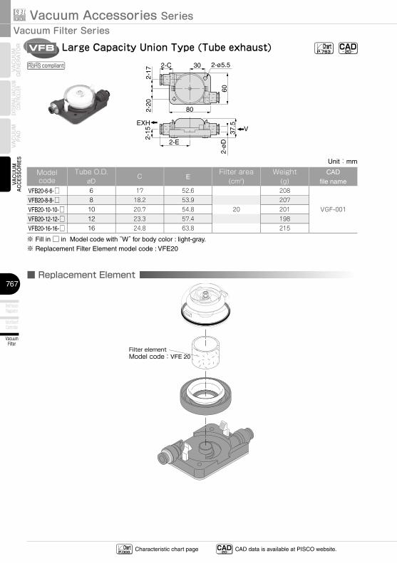
VFB Large Capacity Union Type (Tube exhaust)
2-ø
D
2-15
2-20
2-17
6037
.5
80
2-E
302-C 2-ø5.5
VEXH
CAD-2D-
ChartP.763
■ Replacement Element
Filter elementModel code:VFE 20
compliant
CAD-2D- CAD data is available at PISCO website.Characteristic chart page Chart
P.000
Unit:mm
Model code
Tube O.D.øD
C EFilter area
(cm2)Weight
(g)CAD
file nameVFB20-6-6-□ 6 17 52.6 208
VGF-001VFB20-8-8-□ 8 18.2 53.9 207
VFB20-10-10-□ 10 20.7 54.8 20 201
VFB20-12-12-□ 12 23.3 57.4 198
VFB20-16-16-□ 16 24.8 63.8 215
※ Fill in □ in Model code with “W” for body color : light-gray.※ Replacement Filter Element model code : VFE20
768
Vacuum Filter
Free Holder
Fall Prevention Valve
Small Sensor
Pressure Sensor With Display
LED Pressure Sensor
8mm LED Pressure Sensor
VACUUMACCESSO
RIES
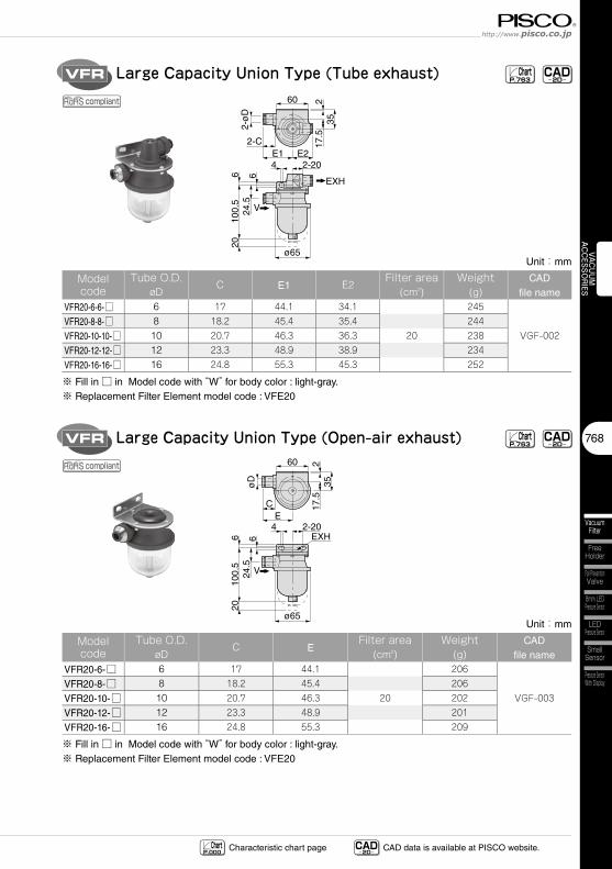
VFR Large Capacity Union Type (Tube exhaust)
2-ø
D24
.510
0.5
206 6
217
.535
60
ø65
2-CE14 2-20
E2
V
EXH
CAD-2D-
ChartP.763
VFR Large Capacity Union Type (Open-air exhaust)
øD
24.5
100.
56 6
217
.535
60
ø65
CE
4 2-20
V
EXH
20
CAD-2D-
ChartP.763
compliant
compliant
CAD-2D- CAD data is available at PISCO website.Characteristic chart page Chart
P.000
Unit:mm
Model code
Tube O.D.øD
C E1 E2Filter area
(cm2)Weight
(g)CAD
file nameVFR20-6-6-□ 6 17 44.1 34.1 245
VGF-002VFR20-8-8-□ 8 18.2 45.4 35.4 244
VFR20-10-10-□ 10 20.7 46.3 36.3 20 238
VFR20-12-12-□ 12 23.3 48.9 38.9 234
VFR20-16-16-□ 16 24.8 55.3 45.3 252
※ Fill in □ in Model code with “W” for body color : light-gray.※ Replacement Filter Element model code : VFE20
Unit:mm
Model code
Tube O.D.øD
C EFilter area
(cm2)Weight
(g)CAD
file nameVFR20-6-□ 6 17 44.1 206
VGF-003VFR20-8-□ 8 18.2 45.4 206
VFR20-10-□ 10 20.7 46.3 20 202
VFR20-12-□ 12 23.3 48.9 201
VFR20-16-□ 16 24.8 55.3 209
※ Fill in □ in Model code with “W” for body color : light-gray.※ Replacement Filter Element model code : VFE20
Vacuum Accessories SeriesVacuum Filter Series
769
Vacuum Filter
Add-on Blow-off Controller
Small Vacuum Regulator
VACU
UMAC
CESS
ORI
ESVA
CU
UM
G
ENER
ATO
REX
TERN
AL VA
CUUM
CO
NTRO
LLER
VAC
UU
MPA
D
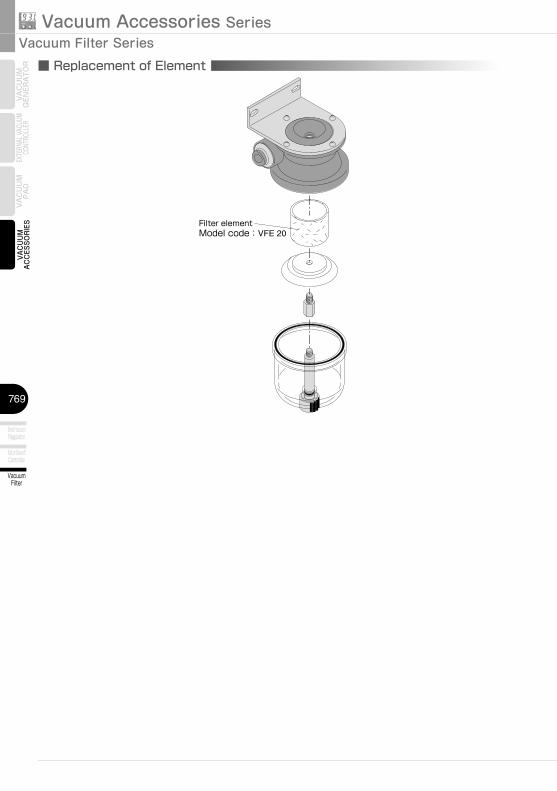
■ Replacement of Element
Filter elementModel code:VFE 20
770
Vacuum Filter
Free Holder
Fall Prevention Valve
Small Sensor
Pressure Sensor With Display
LED Pressure Sensor
8mm LED Pressure Sensor
VACUUMACCESSO
RIES
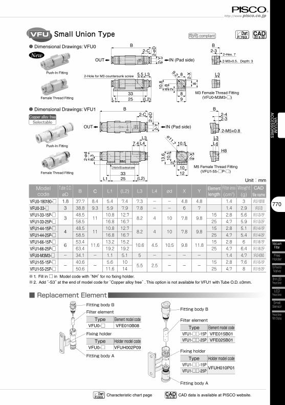
VFU Small Union Type ChartP.763
BB2-3
2-M3×0.5、Depth: 3
L3
2-Hex. 7
M3 Female Thread Fitting(VFU0-M3M3-□)
10.8
6.8
2-X
9.2
98
8
8
2
5.5
2533
(L2)L1
L32-Hole for M3 countersunk screw
2-C
2-ø
D2-
Y IN (Pad side)OUT
■ Replacement Element
Filter elementFitting body B
Fitting body A
TypeVFU0-□
Element model codeVFE010B08
Fixing holder
TypeVFU0-□
Holder model codeVFUH002P09
compliant
B2-C
2-ø
D2-
Y
7.4
25
2-Hole for M3 countersunk screw
33
2-ø
d
(L2)L1
L3L4
8.3
ø11.7
13.6
1210
2
10.5
10.5
B2-4
2-M5×0.8
2-3
L3L4
H8
M5 Female Thread Fitting(VFU1-55-□P-□)
2-X
IN (Pad side)OUT
Filter element
Fitting body B
Fitting body A
TypeVFU1-□□-15PVFU1-□□-25P
Element model codeVFE015B01VFE025B01
Fixing holder
TypeVFU1-□□-15PVFU1-□□-25P
Holder model code
VFUH010P01
Copper alloy freeSelectable
CAD-2D & 3D-
CAD-2D & 3D- CAD data is available at PISCO website.Characteristic chart page Chart
P.000
Unit:mm
Model code
Tube O.D.øD
B C L1 (L2) L3 L4 ød X Y Element length
Filter area(cm2)
Weight(g)
CADfile name
VFU0-180180-□ 1.8 37.7 8.4 5.4 7.4 7.3 - - 4.8 4.8 1.4 3 VFU0-180180
VFU0-33-□ 3 38.8 9.3 5.9 7.9 7.8 - - 6 7 1.4 2.9 VFU0-33
VFU1-33-15P-□3
48.511
10.8 12.78.2 4 10 7.8 9.8
15 2.8 5.6 VFU1-33-15P
VFU1-33-25P-□ 58.5 16.8 16.7 25 4.7 5.9 VFU1-33-25P
VFU1-44-15P-□4
48.511
10.8 12.78.2 4 10 7.8 9.8
15 2.8 5.1 VFU1-44-15P
VFU1-44-25P-□ 58.5 16.8 16.7 25 4.7 5.4 VFU1-44-25P
VFU1-66-15P-□6
53.411.6
13.2 15.210.6 4.5 10.5 9.8 11.8
15 2.8 6 VFU1-66-15P
VFU1-66-25P-□ 63.4 19.2 19.2 25 4.7 6.4 VFU1-66-25P
VFU0-M3M3-□ - 34.1 - 1.1 5.1 5 - - - - 1.4 4.7 VFU0-M3M3
VFU1-55-15P-□-
40.6-
5.6 105.5 2.5 - - -
15 2.8 7.6 VFU1-55-15P
VFU1-55-25P-□ 50.6 11.6 14 25 4.7 8 VFU1-55-25P
※1. Fill in □ in Model code with “NH” for no fixing holder.※2. Add “-S3” at the end of model code for “Copper alloy free” . This option is not available for VFU1 with Tube O.D. ø3mm.
● Dimensional Drawings: VFU0
● Dimensional Drawings: VFU1
Push-In Fitting
Female Thread Fitting
Push-In Fitting
Female Thread Fitting
Vacuum Accessories SeriesVacuum Filter Series
771
Vacuum Filter
Add-on Blow-off Controller
Small Vacuum Regulator
VACU
UMAC
CESS
ORI
ESVA
CU
UM
G
ENER
ATO
REX
TERN
AL VA
CUUM
CO
NTRO
LLER
VAC
UU
MPA
D
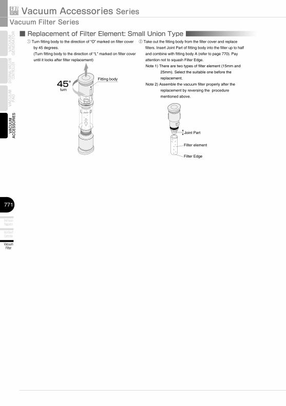
② Take out the fitting body from the filter cover and replace
filters. Insert Joint Part of fitting body into the filter up to half
and combine with fitting body A (refer to page 770). Pay
attention not to squash Filter Edge.
Note 1) There are two types of filter element (15mm and
25mm). Select the suitable one before the
replacement.
Note 2) Assemble the vacuum filter properly after the
replacement by reversing the procedure
mentioned above.
① Turn fitting body to the direction of “O” marked on filter cover
by 45 degrees.
(Turn fitting body to the direction of “L” marked on filter cover
until it locks after filter replacement)
Fitting body
Joint Part
45°turn
Filter element
Filter Edge
■ Replacement of Filter Element: Small Union Type
772
Vacuum Filter
Free Holder
Fall Prevention Valve
Small Sensor
Pressure Sensor With Display
LED Pressure Sensor
8mm LED Pressure Sensor
VACUUMACCESSO
RIES
2-ø4.5
øP
1
øP
3
øP
22-
øD
3
F2
IN (Pad side)
OUT
B3B4 B2
F1
B12-C
L2 L1
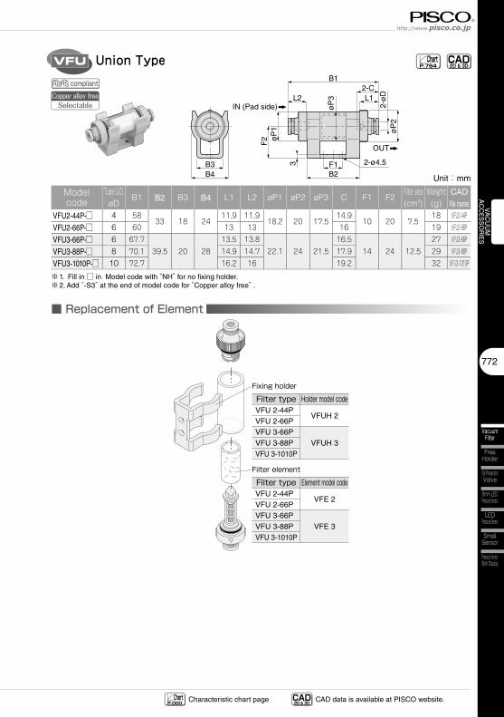
VFU Union Type CAD-2D & 3D- Chart
P.764
■ Replacement of Element
Filter element
Filter typeVFU 2-44PVFU 2-66PVFU 3-66PVFU 3-88PVFU 3-1010P
Element model code
VFE 2
VFE 3
Fixing holder
Filter typeVFU 2-44PVFU 2-66PVFU 3-66PVFU 3-88PVFU 3-1010P
Holder model code
VFUH 2
VFUH 3
compliantCopper alloy free
Selectable
CAD-2D & 3D- CAD data is available at PISCO website.Characteristic chart page Chart
P.000
Unit:mm
Model code
Tube O.D.øD
B1 B2 B3 B4 L1 L2 øP1 øP2 øP3 C F1 F2Filter area(cm2)
Weight(g)
CADfile name
VFU2-44P-□ 4 5833 18 24
11.9 11.918.2 20 17.5
14.910 20 7.5
18 VFU2-44P
VFU2-66P-□ 6 60 13 13 16 19 VFU2-66P
VFU3-66P-□ 6 67.739.5 20 28
13.5 13.822.1 24 21.5
16.514 24 12.5
27 VFU3-66P
VFU3-88P-□ 8 70.1 14.9 14.7 17.9 29 VFU3-88P
VFU3-1010P-□ 10 72.7 16.2 16 19.2 32 VFU3-1010P
※1. Fill in □ in Model code with “NH” for no fixing holder.※2. Add “-S3” at the end of model code for “Copper alloy free” .
Vacuum Accessories SeriesVacuum Filter Series
773
Vacuum Filter
Add-on Blow-off Controller
Small Vacuum Regulator
VACU
UMAC
CESS
ORI
ESVA
CU
UM
G
ENER
ATO
REX
TERN
AL VA
CUUM
CO
NTRO
LLER
VAC
UU
MPA
D
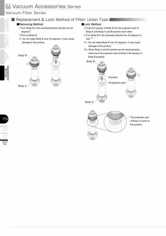
■Removing Method ①Turn Body B in the counterclockwise direction by 45
degrees※.
②Pull out Body B.
※. Do not rotate Body B over 45 degrees. It may cause
damage to the product.
■Lock Method ①Push the keyway of Body B into the projection part of
Body A until Body A and B touches each other.
②Turn Body B in the clockwise direction by 45 degrees to
lock ※1.
※1. Do not rotate Body B over 45 degrees. It may cause
damage to the product.
※2. When Body A and B combine as the drawing below,
make sure the projection part of Body A fits keyway of
Body B properly.
Body A
Body B
Body B
Body A
The projection part
of Body A comes to
this position.
Projection part
Keyway
①
②
②
①
■ Replacement & Lock Method of Filter: Union Type
774
Vacuum Filter
Free Holder
Fall Prevention Valve
Small Sensor
Pressure Sensor With Display
LED Pressure Sensor
8mm LED Pressure Sensor
VACUUMACCESSO
RIES
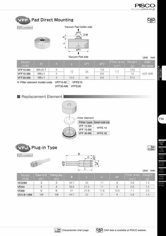
VFF Pad Direct Mounting
øP1
øP22-M
LA
Vaccum Pad holder side
Vacuum Pad side
CAD-2D-
■ Replacement Element
Filter element
Filter typeVFF 15-M4VFF 15-M6VFF 30-M6
Element model code
VFFE 15
VFFE 30
VFJ Plug-in TypeB
C
L
øD
1ø
P
øD
2
ChartP.764
compliant
compliant
CAD-2D- CAD data is available at PISCO website.Characteristic chart page Chart
P.000
Unit:mm
Model code
Tube O.D.øD1
Fitting dia.øD2
B L C øPFilter area
(cm2)Weight
(g)VFJ33M 3 3 34.7 22 11 8 0.8 1.4
VFJ44 4 4 38.6 21.5 11 8 0.8 1.5
VFJ66 6 6 41 21.8 11.6 10.5 1.1 2.5
VFJ1/8-1/8M 1/8 1/8 34.7 22 11 8 0.8 1.4
Unit:mm
Model code M A L øP1 øP2
Filter area(cm2)
Weight(g)
CADfile name
VFF15-M4 M4×0.7 312 25
7.81.7
13.5VGF-006VFF15-M6 M6×1 4 8.8 14
VFF30-M6 M6×1 4 15.5 40 8.8 7 37.5
※ Filter element model code VFF15-M□:VFFE15 VFF30-M6:VFFE30
Vacuum Accessories SeriesVacuum Filter Series
775
Vacuum Filter
Add-on Blow-off Controller
Small Vacuum Regulator
VACU
UMAC
CESS
ORI
ESVA
CU
UM
G
ENER
ATO
REX
TERN
AL VA
CUUM
CO
NTRO
LLER
VAC
UU
MPA
D
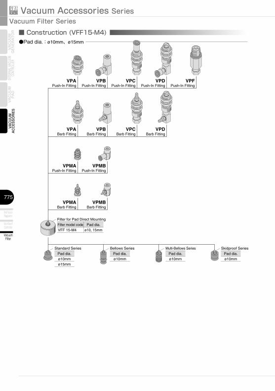
■ Construction (VFF15-M4)●Pad dia.:ø10mm、ø15mm
VPAPush-In Fitting
VPABarb Fitting
VPBBarb Fitting
VPCBarb Fitting
VPDBarb Fitting
VPMAPush-In Fitting
VPMBPush-In Fitting
VPMABarb Fitting
VPMBBarb Fitting
VPBPush-In Fitting
VPCPush-In Fitting
VPDPush-In Fitting
VPFPush-In Fitting
Filter model codeVFF 15-M4
Pad dia.ø10, 15mm
Filter for Pad Direct Mounting
Pad dia.ø10mmø15mm
Standard SeriesPad dia.ø10mm
Bellows SeriesPad dia.ø10mm
Pad dia.ø10mm
Multi-Bellows Series Skidproof Series
776
Vacuum Filter
Free Holder
Fall Prevention Valve
Small Sensor
Pressure Sensor With Display
LED Pressure Sensor
8mm LED Pressure Sensor
VACUUMACCESSO
RIES
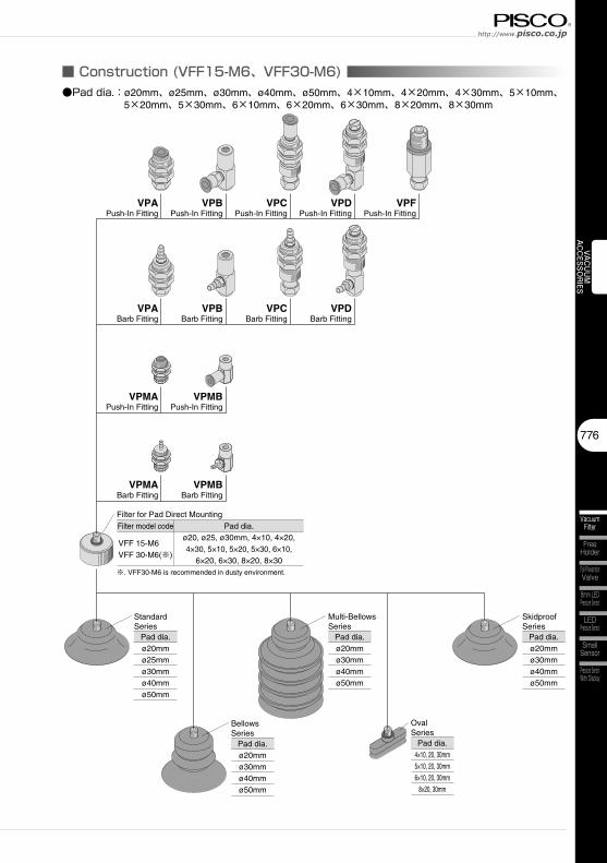
■ Construction (VFF15-M6、VFF30-M6)●Pad dia.:ø20mm、ø25mm、ø30mm、ø40mm、ø50mm、4×10mm、4×20mm、4×30mm、5×10mm、
5×20mm、5×30mm、6×10mm、6×20mm、6×30mm、8×20mm、8×30mm
VPAPush-In Fitting
VPABarb Fitting
VPBBarb Fitting
VPCBarb Fitting
VPDBarb Fitting
VPMAPush-In Fitting
VPMBPush-In Fitting
VPMABarb Fitting
VPMBBarb Fitting
VPBPush-In Fitting
VPCPush-In Fitting
VPDPush-In Fitting
VPFPush-In Fitting
Pad dia.ø20mmø25mmø30mmø40mmø50mm
Standard Series
Pad dia.ø20mmø30mmø40mmø50mm
Skidproof Series
Pad dia.ø20mmø30mmø40mmø50mm
Multi-Bellows Series
Pad dia.ø20mmø30mmø40mmø50mm
Bellows Series
Pad dia.4×10, 20, 30mm5×10, 20, 30mm6×10, 20, 30mm
8×20, 30mm
Oval Series
Filter model code
VFF 15-M6VFF 30-M6(※)
Pad dia.ø20, ø25, ø30mm, 4×10, 4×20,4×30, 5×10, 5×20, 5×30, 6×10,
6×20, 6×30, 8×20, 8×30
Filter for Pad Direct Mounting
※. VFF30-M6 is recommended in dusty environment.
Vacuum Accessories SeriesVacuum Filter Series
777
Vacuum Filter
Add-on Blow-off Controller
Small Vacuum Regulator
VACU
UMAC
CESS
ORI
ESVA
CU
UM
G
ENER
ATO
REX
TERN
AL VA
CUUM
CO
NTRO
LLER
VAC
UU
MPA
D
35
Safety Instructions
SAFETY Instructions
Warning
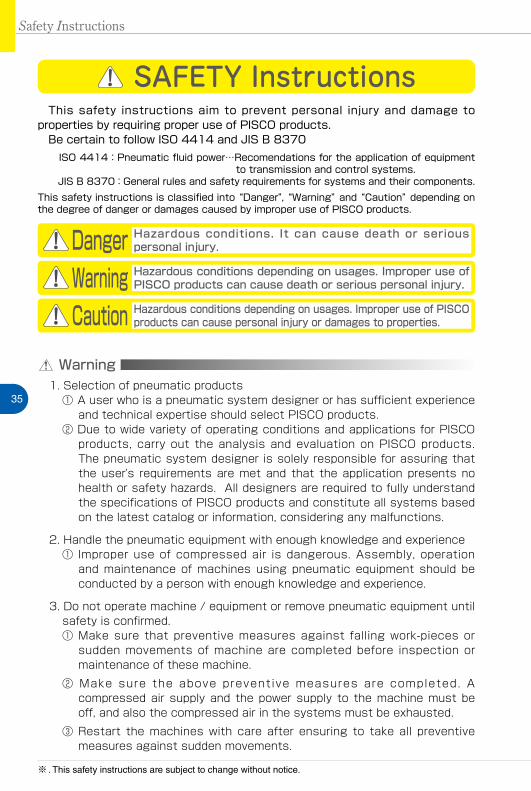
This safety instructions aim to prevent personal injury and damage to properties by requiring proper use of PISCO products. Be certain to follow ISO 4414 and JIS B 8370
ISO 4414:Pneumatic fluid power…Recomendations for the application of equipment to transmission and control systems.
JIS B 8370:General rules and safety requirements for systems and their components.This safety instructions is classified into “Danger”, “Warning” and “Caution” depending on the degree of danger or damages caused by improper use of PISCO products.
1. Selection of pneumatic products① A user who is a pneumatic system designer or has sufficient experience
and technical expertise should select PISCO products.② Due to wide variety of operating conditions and applications for PISCO
products, carry out the analysis and evaluation on PISCO products. The pneumatic system designer is solely responsible for assuring that the user's requirements are met and that the application presents no health or safety hazards. All designers are required to fully understand the specifications of PISCO products and constitute all systems based on the latest catalog or information, considering any malfunctions.
2. Handle the pneumatic equipment with enough knowledge and experience① Improper use of compressed air is dangerous. Assembly, operation
and maintenance of machines using pneumatic equipment should be conducted by a person with enough knowledge and experience.
3. Do not operate machine / equipment or remove pneumatic equipment until safety is confirmed.① Make sure that preventive measures against falling work-pieces or
sudden movements of machine are completed before inspection or maintenance of these machine.
② Make sure the above preventive measures are completed. A compressed air supply and the power supply to the machine must be off, and also the compressed air in the systems must be exhausted.
③ Restart the machines with care after ensuring to take all preventive measures against sudden movements.
Danger Hazardous conditions. It can cause death or serious personal injury.
Warning Hazardous conditions depending on usages. Improper use of PISCO products can cause death or serious personal injury.
Caution Hazardous conditions depending on usages. Improper use of PISCO products can cause personal injury or damages to properties.
※ . This safety instructions are subject to change without notice.
http://www.pisco.co.jphttp://www.pisco.co.jp
36
Disclaimer1. PISCO does not take any responsibility for any incidental or indirect
loss, such as production line stop, interruption of business, loss of benefits, personal injury, etc., caused by any failure on use or application of PISCO products.
2. PISCO does not take any responsibility for any loss caused by natural disasters, fires not related to PISCO products, acts by third parties, and intentional or accidental damages of PISCO products due to incorrect usage.
3. PISCO does not take any responsibility for any loss caused by improper usage of PISCO products such as exceeding the specification limit or not following the usage the published instructions and catalog allow.
4. PISCO does not take any responsibility for any loss caused by remodeling of PISCO products, or by combinational use with non-PISCO products and other software systems.
5. The damages caused by the defect of Pisco products shall be covered but limited to the full amount of the PISCO products paid by the customer.
37
Safety Instructions
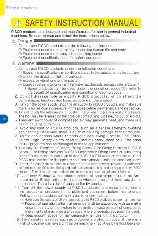
SAFETY INSTRUCTION MANUAL
Danger1. Do not use PISCO products for the following applications.
① Equipment used for maintaining / handling human life and body.② Equipment used for moving / transporting human.③ Equipment specifically used for safety purposes.
Warning1. Do not use PISCO products under the following conditions.
① Beyond the specifications or conditions stated in the catalog, or the instructions.② Under the direct sunlight or outdoors.③ Excessive vibrations and impacts.④ Exposure / adhere to corrosive gas, inflammable gas, chemicals, seawater, water and vapor. *
* Some products can be used under the condition above(④), refer to the details of specification and condition of each product.
2. Do not disassemble or modify PISCO products, which affect the performance, function, and basic structure of the product.
3. Turn off the power supply, stop the air supply to PISCO products, and make sure there is no residual air pressure in the pipes before maintenance and inspection.
4. Do not touch the release-ring of push-in fitting when there is a working pressure. The lock may be released by the physical contact, and tube may fly out or slip out.
5. Frequent switchover of compressed air may generate heat, and there is a risk of causing burn injury.
6. Avoid any load on PISCO products, such as a tensile strength, twisting and bending. Otherwise, there is a risk of causing damage to the products.
7. As for applications where threads or tubes swing / rotate, use Rotary Joints, High Rotary Joints or Multi-Circuit Rotary Block only. The other PISCO products can be damaged in these applications.
8. Use only Die Temperature Control Fitting Series, Tube Fitting Stainless SUS316 Series, Tube Fitting Stainless SUS316 Compression Fitting Series or Tube Fitting Brass Series under the condition of over 60℃ (140°F) water or thermal oil. Other PISCO products can be damaged by heat and hydrolysis under the condition above.
9. As for the condition required to dissipate static electricity or provide an antistatic performance, use EG series fitting and antistatic products only, and do not use other PISCO products. There is a risk that static electricity can cause system defects or failures.
10. Use only Fittings with a characteristic of spatter-proof such as Anti-spatter or Brass series in a place where flame and weld spatter is produced. There is a risk of causing fire by sparks.
11. Turn off the power supply to PISCO products, and make sure there is no residual air pressure in the pipes and equipment before maintenance. Follow the instructions below in order to ensure safety.① Make sure the safety of all systems related to PISCO products before maintenance.② Restart of operation after maintenance shall be proceeded with care after
ensuring safety of the system by preventive measures against unexpected movements of machines and devices where pneumatic equipment is used.
③ Keep enough space for maintenance when designing a circuit.12. Take safety measures such as providing a protection cover if there is a
risk of causing damages or fires on machine / facilities by a fluid leakage.
PISCO products are designed and manufactured for use in general industrial machines. Be sure to read and follow the instructions below.
http://www.pisco.co.jphttp://www.pisco.co.jp
38
Caution1. Remove dusts or drain before piping. They may get into the peripheral
machine / facilities and cause malfunction.2. When inserting an ultra-soft tube into push-in fitting, make sure to place
an Insert Ring into the tube edge. There is a risk of causing the escape of tube and a fluid leakage without using an Insert Ring.
3. The product incorporating NBR as seal rubber material has a risk of malfunction caused by ozone crack. Ozone exists in high concentrations in static elimination air, clean-room, and near the high-voltage motors, etc. As a countermeasure, material change from NBR to HNBR or FKM is necessary. Consult with PISCO for more information.
4. Special option “Oil-free” products may cause a very small amount of a fluid leakage. When a fluid medium is liquid or the products are required to be used in harsh environments, contact us for further information.
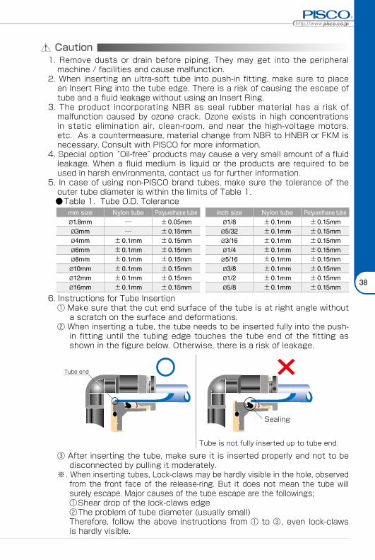
5. In case of using non-PISCO brand tubes, make sure the tolerance of the outer tube diameter is within the limits of Table 1.
●Table 1. Tube O.D. Tolerancemm size Nylon tube Polyurethane tube inch size Nylon tube Polyurethane tubeø1.8mm ─ ±0.05mm ø1/8 ±0.1mm ±0.15mmø3mm ─ ±0.15mm ø5/32 ±0.1mm ±0.15mmø4mm ±0.1mm ±0.15mm ø3/16 ±0.1mm ±0.15mmø6mm ±0.1mm ±0.15mm ø1/4 ±0.1mm ±0.15mmø8mm ±0.1mm ±0.15mm ø5/16 ±0.1mm ±0.15mmø10mm ±0.1mm ±0.15mm ø3/8 ±0.1mm ±0.15mmø12mm ±0.1mm ±0.15mm ø1/2 ±0.1mm ±0.15mmø16mm ±0.1mm ±0.15mm ø5/8 ±0.1mm ±0.15mm
6. Instructions for Tube Insertion① Make sure that the cut end surface of the tube is at right angle without
a scratch on the surface and deformations.② When inserting a tube, the tube needs to be inserted fully into the push-
in fitting until the tubing edge touches the tube end of the fitting as shown in the figure below. Otherwise, there is a risk of leakage.
Tube end
Sealing
Tube is not fully inserted up to tube end.
③ After inserting the tube, make sure it is inserted properly and not to be disconnected by pulling it moderately.
※. When inserting tubes, Lock-claws may be hardly visible in the hole, observed from the front face of the release-ring. But it does not mean the tube will surely escape. Major causes of the tube escape are the followings; ①Shear drop of the lock-claws edge②The problem of tube diameter (usually small)Therefore, follow the above instructions from ① to ③, even lock-claws is hardly visible.
39
7. Instructions for Tube Disconnection① Make sure there is no air pressure inside of the tube, before disconnecting it.② Push the release-ring of the push-in fitting evenly and deeply enough to
pull out the tube toward oneself. By insufficient pushing of the release-ring, the tube may not be pulled out or damaged by scratch, and tube shavings may remain inside of the fitting, which may cause the leakage later.
8. Instructions for Installing a fitting① When installing a fitting, use proper tools to tighten a hexagonal-column
or an inner hexagonal socket. When inserting a hex key into the inner hexagonal socket of the fitting, be careful so that the tool does not touch lock-claws. The deformation of lock-claws may result in a poor performance of systems or an escape of the tube.
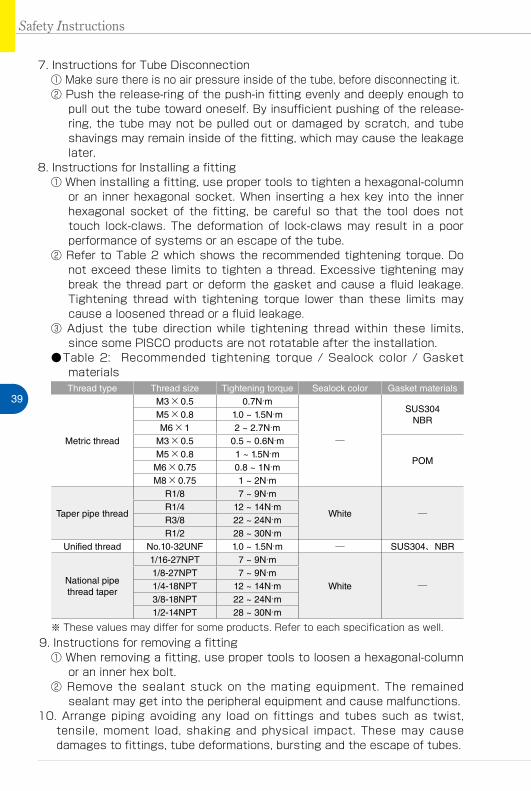
② Refer to Table 2 which shows the recommended tightening torque. Do not exceed these limits to tighten a thread. Excessive tightening may break the thread part or deform the gasket and cause a fluid leakage. Tightening thread with tightening torque lower than these limits may cause a loosened thread or a fluid leakage.
③ Adjust the tube direction while tightening thread within these limits, since some PISCO products are not rotatable after the installation.
●Table 2: Recommended tightening torque / Sealock color / Gasket materialsThread type Thread size Tightening torque Sealock color Gasket materials
Metric thread
M3×0.5 0.7N·m
─
SUS304NBR
M5×0.8 1.0 ~ 1.5N·mM6×1 2 ~ 2.7N·m
M3×0.5 0.5 ~ 0.6N·m
POMM5×0.8 1 ~ 1.5N·mM6×0.75 0.8 ~ 1N·mM8×0.75 1 ~ 2N·m
Taper pipe thread
R1/8 7 ~ 9N·m
White ─R1/4 12 ~ 14N·mR3/8 22 ~ 24N·mR1/2 28 ~ 30N·m
Unified thread No.10-32UNF 1.0 ~ 1.5N·m ─ SUS304、NBR
National pipe thread taper
1/16-27NPT 7 ~ 9N·m
White ─1/8-27NPT 7 ~ 9N·m1/4-18NPT 12 ~ 14N·m3/8-18NPT 22 ~ 24N·m1/2-14NPT 28 ~ 30N·m
※ These values may differ for some products. Refer to each specification as well.9. Instructions for removing a fitting
① When removing a fitting, use proper tools to loosen a hexagonal-column or an inner hex bolt.
② Remove the sealant stuck on the mating equipment. The remained sealant may get into the peripheral equipment and cause malfunctions.
10. Arrange piping avoiding any load on fittings and tubes such as twist, tensile, moment load, shaking and physical impact. These may cause damages to fittings, tube deformations, bursting and the escape of tubes.
Safety Instructions
Vacuum Generator SeriesVacuum Generator
47
VAC
UU
M
GEN
ERA
TOR
Common Safety Instructions for Vacuum Series
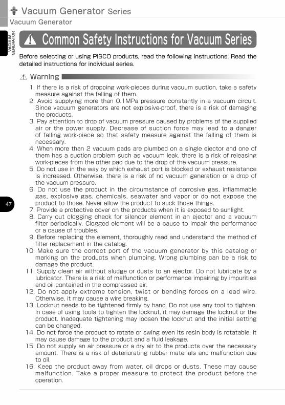
Warning
Before selecting or using PISCO products, read the following instructions. Read the detailed instructions for individual series.
1. If there is a risk of dropping work-pieces during vacuum suction, take a safety measure against the falling of them.
2. Avoid supplying more than 0.1MPa pressure constantly in a vacuum circuit. Since vacuum generators are not explosive-proof, there is a risk of damaging the products.
3. Pay attention to drop of vacuum pressure caused by problems of the supplied air or the power supply. Decrease of suction force may lead to a danger of falling work-piece so that safety measure against the falling of them is necessary.
4. When more than 2 vacuum pads are plumbed on a single ejector and one of them has a suction problem such as vacuum leak, there is a risk of releasing work-pieces from the other pad due to the drop of the vacuum pressure.
5. Do not use in the way by which exhaust port is blocked or exhaust resistance is increased. Otherwise, there is a risk of no vacuum generation or a drop of the vacuum pressure.
6. Do not use the product in the circumstance of corrosive gas, inflammable gas, explosive gas, chemicals, seawater and vapor or do not expose the product to those. Never allow the product to suck those things.
7. Provide a protective cover on the products when it is exposed to sunlight.8. Carry out clogging check for silencer element in an ejector and a vacuum
filter periodically. Clogged element will be a cause to impair the performance or a cause of troubles.
9. Before replacing the element, thoroughly read and understand the method of filter replacement in the catalog.
10. Make sure the correct port of the vacuum generator by this catalog or marking on the products when plumbing. Wrong plumbing can be a risk to damage the product.
11. Supply clean air without sludge or dusts to an ejector. Do not lubricate by a lubricator. There is a risk of malfunction or performance impairing by impurities and oil contained in the compressed air.
12. Do not apply extreme tension, twist or bending forces on a lead wire. Otherwise, it may cause a wire breaking.
13. Locknut needs to be tightened firmly by hand. Do not use any tool to tighten. In case of using tools to tighten the locknut, it may damage the locknut or the product. Inadequate tightening may loosen the locknut and the initial setting can be changed.
14. Do not force the product to rotate or swing even its resin body is rotatable. It may cause damage to the product and a fluid leakage.
15. Do not supply an air pressure or a dry air to the products over the necessary amount. There is a risk of deteriorating rubber materials and malfunction due to oil.
16. Keep the product away from water, oil drops or dusts. These may cause malfunction. Take a proper measure to protect the product before the operation.
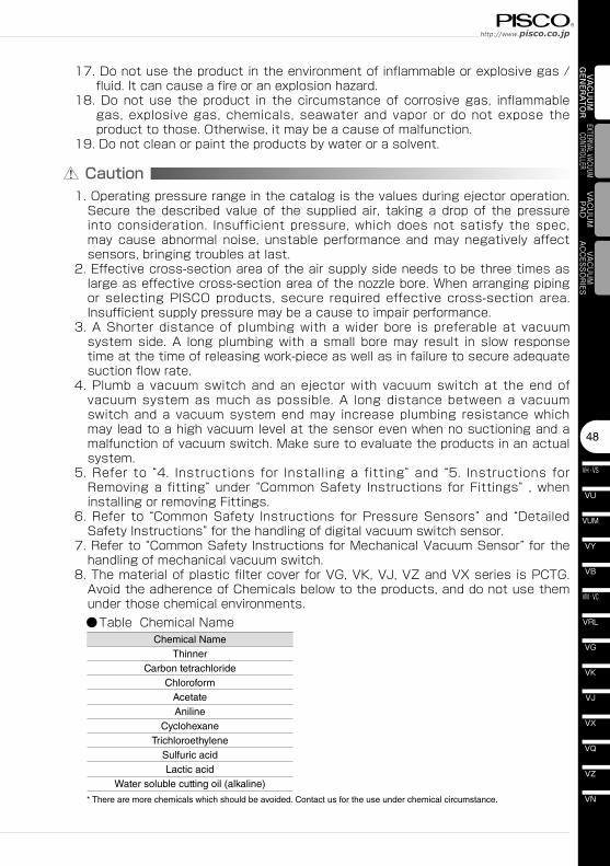
Chemical NameThinner
Carbon tetrachlorideChloroform
AcetateAniline
CyclohexaneTrichloroethylene
Sulfuric acidLactic acid
Water soluble cutting oil (alkaline)
* There are more chemicals which should be avoided. Contact us for the use under chemical circumstance.
48
VN
VZ
VQ
VX
VJ
VK
VG
VM · VC
VB
VU
VH · VS
VY
VUM
VRL
VAC
UU
M
GEN
ERA
TOR
EXTERNAL VACUUM CONTROLLER
VAC
UU
MPA
DVACUUM
ACCESSORIES
Caution1. Operating pressure range in the catalog is the values during ejector operation.
Secure the described value of the supplied air, taking a drop of the pressure into consideration. Insufficient pressure, which does not satisfy the spec, may cause abnormal noise, unstable performance and may negatively affect sensors, bringing troubles at last.
2. Effective cross-section area of the air supply side needs to be three times as large as effective cross-section area of the nozzle bore. When arranging piping or selecting PISCO products, secure required effective cross-section area. Insufficient supply pressure may be a cause to impair performance.
3. A Shorter distance of plumbing with a wider bore is preferable at vacuum system side. A long plumbing with a small bore may result in slow response time at the time of releasing work-piece as well as in failure to secure adequate suction flow rate.
4. Plumb a vacuum switch and an ejector with vacuum switch at the end of vacuum system as much as possible. A long distance between a vacuum switch and a vacuum system end may increase plumbing resistance which may lead to a high vacuum level at the sensor even when no suctioning and a malfunction of vacuum switch. Make sure to evaluate the products in an actual system.
5. Refer to “4. Instructions for Installing a fitting” and “5. Instructions for Removing a fitting” under “Common Safety Instructions for Fittings” , when installing or removing Fittings.
6. Refer to “Common Safety Instructions for Pressure Sensors” and “Detailed Safety Instructions” for the handling of digital vacuum switch sensor.
7. Refer to “Common Safety Instructions for Mechanical Vacuum Sensor” for the handling of mechanical vacuum switch.
8. The material of plastic filter cover for VG, VK, VJ, VZ and VX series is PCTG. Avoid the adherence of Chemicals below to the products, and do not use them under those chemical environments.
●Table Chemical Name
17. Do not use the product in the environment of inflammable or explosive gas / fluid. It can cause a fire or an explosion hazard.
18. Do not use the product in the circumstance of corrosive gas, inflammable gas, explosive gas, chemicals, seawater and vapor or do not expose the product to those. Otherwise, it may be a cause of malfunction.
19. Do not clean or paint the products by water or a solvent.
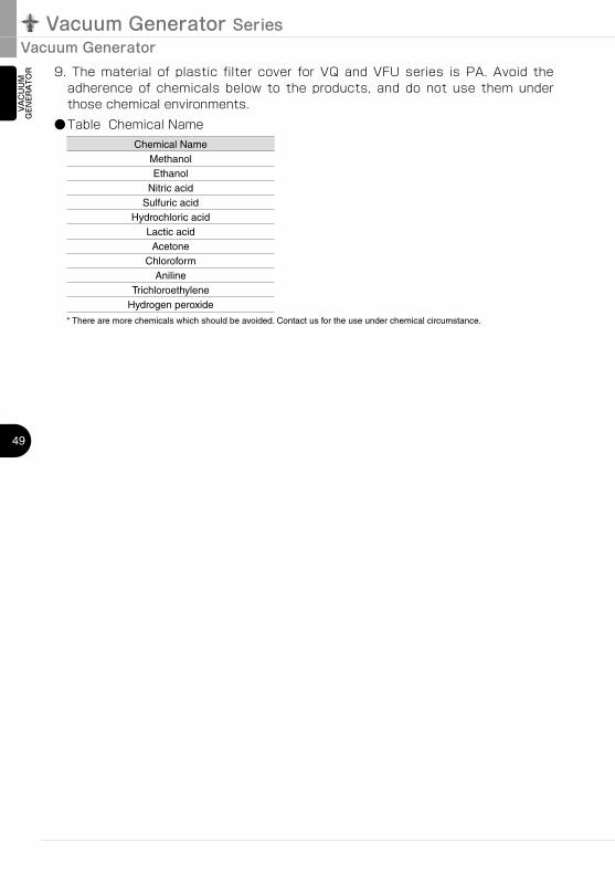
Chemical NameMethanolEthanol
Nitric acidSulfuric acid
Hydrochloric acidLactic acidAcetone
ChloroformAniline
TrichloroethyleneHydrogen peroxide
Vacuum Generator SeriesVacuum Generator
49
VAC
UU
M
GEN
ERA
TOR 9. The material of plastic filter cover for VQ and VFU series is PA. Avoid the
adherence of chemicals below to the products, and do not use them under those chemical environments.
●Table Chemical Name
* There are more chemicals which should be avoided. Contact us for the use under chemical circumstance.