ADDENDUM NUMBER: 7 UNC CHARLOTTE ELM, MAPLE … · 1. Copper, Solder-Joint Fittings: ASME B16.18,...
72
ADDENDUM NUMBER: 7 UNC CHARLOTTE ELM, MAPLE AND PINE RESIDENCE HALLS RENOVATIONS SCO#120994003 - Code: 41226 - Item 307 PROJECT NUMBER 3523-00 February 15, 2016 NOTICE TO CONTRACTORS This Addendum issued prior to receipt of Bid shall and does hereby become a part of the Construction Documents for the above project. All principal Contractors shall be responsible for seeing that their Subcontractors are properly apprised of the contents of this Addendum. All information contained in this Addendum shall supersede and shall take precedence over any conflicting information in the original Bidding Documents dated 12/18/15 and all previous Addendum. All Contractors shall acknowledge receipt of this Addendum in the space provided in the Proposal Form. Failure to do so may subject Bidder to disqualification. A. CHANGES TO PRIOR ADDENDA No changes. B. CHANGES TO BIDDING REQUIREMENTS No changes. C. CHANGES TO CONDITIONS OF THE CONTRACT No changes. D. CHANGES TO SPECIFICATIONS SECTION - 00 00 01 NOTICE TO BIDDERS a. Bid date has been changed to Monday, February 22, 2016 at 2:00 pm in Room 119 of the Facilities Management Building. SECTION - 22 11 13 FACILITY WATER DISTRIBUTION PIPING a. Spec Section reissued in its entirety. b. Remove ISCO as approved polypropylene piping manufacturer. It is not approved by University. SECTION - 23 07 19 HVAC PIPING INSULATION a. Spec Section reissued in its entirety. b. Section Re-issued. Clarified insulation requirements. SECTION - 23 09 00 INSTRUMENTATION AND CONTROL FOR HVAC a. Spec Section reissued in its entirety. b. Remove “Energy Control Solutions” from approved control systems manufacturers list.
Transcript of ADDENDUM NUMBER: 7 UNC CHARLOTTE ELM, MAPLE … · 1. Copper, Solder-Joint Fittings: ASME B16.18,...

ADDENDUM NUMBER: 7
UNC CHARLOTTE ELM, MAPLE AND PINE RESIDENCE HALLS RENOVATIONS SCO#120994003 - Code: 41226 - Item 307 PROJECT NUMBER 3523-00 February 15, 2016
NOTICE TO CONTRACTORS This Addendum issued prior to receipt of Bid shall and does hereby become a part of the Construction Documents for the above project. All principal Contractors shall be responsible for seeing that their Subcontractors are properly apprised of the contents of this Addendum. All information contained in this Addendum shall supersede and shall take precedence over any conflicting information in the original Bidding Documents dated 12/18/15 and all previous Addendum. All Contractors shall acknowledge receipt of this Addendum in the space provided in the Proposal Form. Failure to do so may subject Bidder to disqualification. A. CHANGES TO PRIOR ADDENDA No changes. B. CHANGES TO BIDDING REQUIREMENTS No changes. C. CHANGES TO CONDITIONS OF THE CONTRACT No changes. D. CHANGES TO SPECIFICATIONS
SECTION - 00 00 01 NOTICE TO BIDDERS a. Bid date has been changed to Monday, February 22, 2016 at 2:00 pm in Room 119 of the Facilities Management Building.
SECTION - 22 11 13 FACILITY WATER DISTRIBUTION PIPING a. Spec Section reissued in its entirety.
b. Remove ISCO as approved polypropylene piping manufacturer. It is not approved by University.
SECTION - 23 07 19 HVAC PIPING INSULATION a. Spec Section reissued in its entirety.
b. Section Re-issued. Clarified insulation requirements.
SECTION - 23 09 00 INSTRUMENTATION AND CONTROL FOR HVAC a. Spec Section reissued in its entirety.
b. Remove “Energy Control Solutions” from approved control systems manufacturers list.
ADDENDUM NUMBER: 7
UNC CHARLOTTE ELM, MAPLE AND PINE RESIDENCE HALLS RENOVATIONS
Page 2 of 2
SECTION - 23 21 13 HYDRONIC PIPING a. Spec Section reissued in its entirety.
b. Remove ISCO as approved polypropylene piping manufacturer. It is not approved by University
SECTION - 23 81 01 TERMINAL HEAT TRANSFER UNITS a. Spec Section reissued in its entirety.
b. Added Indeeco as approved manufacturer.
SECTION - 23 81 26 DUCTLESS SPLIT SYSTEM AIR CONDITIONERS a. Spec Section reissued in its entirety.
b. Added LG as approved manufacturer.
E. CHANGES TO DRAWINGS
No changes
ENCLOSURES: SPECIFICATION SECTIONS 22 11 13 FACILITY WATER DISTRIBUTION PIPING 23 07 19 HVAC PIPING INSULATION 23 09 00 INSTRUMENTATION AND CONTROL FOR HVAC 23 21 13 HYDRONIC PIPING 23 81 01 TERMINAL HEAT TRANSFER UNITS 23 81 26 DUCTLESS SPLIT SYSTEM AIR CONDITIONERS
End of Addendum
The University of North Carolina at Charlotte 3523-01 Elm, Maple, Pine Residence Halls Renovations SCO# 12-09940-03A Building Package Code: 41226 Item: 307
FACILITY WATER DISTRIBUTION PIPING 22 11 13-1
SECTION 22 11 13
FACILITY WATER DISTRIBUTION PIPING
PART 1 - GENERAL
1.01 RELATED DOCUMENTS
A. Drawings and general provisions of the Contract, including General and Supplementary Conditions and Division 01 Specification Sections, apply to this Section.
1.02 SUMMARY
A. This Section includes water-distribution piping and related components outside the building for water service and fire-service mains.
B. Utility-furnished products include water meters that will be furnished to the site, ready for installation.
1.03 DEFINITIONS
A. EPDM: Ethylene propylene diene terpolymer rubber.
B. LLDPE: Linear, low-density polyethylene plastic.
C. PA: Polyamide (nylon) plastic.
D. PE: Polyethylene plastic.
E. PP: Polypropylene plastic.
F. PVC: Polyvinyl chloride plastic.
G. RTRF: Reinforced thermosetting resin (fiberglass) fittings.
H. RTRP: Reinforced thermosetting resin (fiberglass) pipe.
1.04 SUBMITTALS
A. Product Data: For each type of product indicated.
B. Shop Drawings: Detail precast concrete vault assemblies and indicate dimensions, method of field assembly, and components. 1. Wiring Diagrams: Power, signal, and control wiring for alarms.
C. Coordination Drawings: For piping and specialties including relation to other services in same area, drawn to scale. Show piping and specialty sizes and valves, meter and specialty locations, and elevations.
D. Field quality-control test reports.
E. Operation and Maintenance Data: For water valves and specialties to include in emergency, operation, and maintenance manuals.
1.05 QUALITY ASSURANCE
A. Regulatory Requirements: 1. Comply with standards of authorities having jurisdiction for potable-water-service piping,
including materials, installation, testing, and disinfection. 2. Comply with standards of authorities having jurisdiction for fire-suppression water-service
piping, including materials, hose threads, installation, and testing.
B. Piping materials shall bear label, stamp, or other markings of specified testing agency.
C. Electrical Components, Devices, and Accessories: Listed and labeled as defined in NFPA
The University of North Carolina at Charlotte 3523-01 Elm, Maple, Pine Residence Halls Renovations SCO# 12-09940-03A Building Package Code: 41226 Item: 307
FACILITY WATER DISTRIBUTION PIPING 22 11 13-2
70, Article 100, by a testing agency acceptable to authorities having jurisdiction, and marked for intended use.
D. Comply with ASTM F 645 for selection, design, and installation of thermoplastic water piping.
E. Comply with FMG's "Approval Guide" or UL's "Fire Protection Equipment Directory" for fire- service-main products.
F. NFPA Compliance: Comply with NFPA 24 for materials, installations, tests, flushing, and valve and hydrant supervision for fire-service-main piping for fire suppression.
G. NSF Compliance: 1. Comply with NSF 61 for materials for water-service piping and specialties for domestic
water.
H. Fusion Welding: Certify training per Manufacturer’s standards for each installer.
I. Manufacture of PP-R pipe must also manufacture same PP-R resin.
J. Special Engineered PP-R products shall be certified by NSF International as complying with NSF 14.
K. Provider of PP-R material shall have an Aquatherm certified master trainer on staff and have at least 8 years of experience in the US with this.
L. Supplier of PP-R material shall have at least 8 years of experience in the US with job names and reference of same ages or greater.
1.06 DELIVERY, STORAGE, AND HANDLING
A. Preparation for Transport: Prepare valves, including fire hydrants, according to the following: 1. Ensure that valves are dry and internally protected against rust and corrosion. 2. Protect valves against damage to threaded ends and flange faces. 3. Set valves in best position for handling. Set valves closed to prevent rattling.
B. During Storage: Use precautions for valves, including fire hydrants, according to the following: 1. Do not remove end protectors unless necessary for inspection; then reinstall for storage. 2. Protect from weather. Store indoors and maintain temperature higher than ambient dew-
point temperature. Support off the ground or pavement in watertight enclosures when outdoor storage is necessary.
C. Handling: Use sling to handle valves and fire hydrants if size requires handling by crane or lift. Rig valves to avoid damage to exposed parts. Do not use handwheels or stems as lifting or rigging points.
D. Deliver piping with factory-applied end caps. Maintain end caps through shipping, storage, and handling to prevent pipe-end damage and to prevent entrance of dirt, debris, and moisture.
E. Protect stored piping from moisture and dirt. Elevate above grade. Do not exceed structural capacity of floor when storing inside.
F. Protect flanges, fittings, and specialties from moisture and dirt.
G. Store plastic piping protected from direct sunlight. Support to prevent sagging and bending.
1.07 PROJECT CONDITIONS
A. Interruption of Existing Water-Distribution Service: Do not interrupt service to facilities occupied by Owner or others unless permitted under the following conditions and then only after arranging to provide temporary water-distribution service according to requirements indicated: 1. Notify General Contractor no fewer than two days in advance of proposed interruption of
service.
The University of North Carolina at Charlotte 3523-01 Elm, Maple, Pine Residence Halls Renovations SCO# 12-09940-03A Building Package Code: 41226 Item: 307
FACILITY WATER DISTRIBUTION PIPING 22 11 13-3
2. Do not proceed with interruption of water-distribution service without General Contractor’s and Owner's written permission.
B. Verify existing utility locations. Contact utility-locating service for area where Project is located.
C. Verify that water system piping may be installed in compliance with original design and referenced standards.
D. Site Information: Reports on subsurface condition investigations made during the design of the Project are available for informational purposes only; data in reports are not intended as representations or warranties of accuracy or continuity of conditions (between soil borings). Owner assumes no responsibility for interpretations or conclusions drawn from this information.
1.08 COORDINATION
A. Coordinate connection to water main with utility company.
PART 2 - PRODUCTS
2.01 COPPER TUBE AND FITTINGS
A. Soft Copper Tube: ASTM B 88, Type K, water tube, annealed temper. 1. Copper, Solder-Joint Fittings: ASME B16.18, cast-copper-alloy or ASME B16.22, wrought-
copper, solder-joint pressure type. Furnish only wrought-copper fittings if indicated. 2. Copper, Pressure-Seal Fittings:
a. Manufacturers: Subject to compliance with requirements, provide products by one of the following: 1) Elkhart Products Corporation; APOLLOXPRESS. 2) NIBCO INC. 3) Viega; Plumbing & Heating Systems.
b. NPS 2 and Smaller: Wrought-copper fitting with EPDM O-ring seal in each end. c. NPS 2-1/2 to NPS 4: Bronze fitting with stainless-steel grip ring and EPDM O-ring seal
in each end.
2.02 POLYPROPYLENE (PP-R) PIPE AND FITTINGS
A. Pipe and Piping Products. 1. Pipe shall be manufactured from a PP-R resin (Fusiolen) meeting the short-term properties
and long-term strength requirements of ASTM F 2389. The pipe shall contain no rework or recycled materials except that generated in the manufacturer's own plant from resin of the same specification from the same raw material. All pipe shall be made in an extrusion process. Domestic hot water shall contain a fiber layer (faser) to restrict thermal expansion. All pipe shall comply with the rated pressure requirements of ASTM F 2389. All pipe shall be certified by NSF International as complying with NSF 14, NSF 61, and ASTM F 2389 or CSA B137.11.
2. Pipe shall be Aquatherm® Green Pipe®, or Green Pipe® MF (Faser®), available from Aquatherm, NA. Piping specifications and ordering information are available at www.aquatherm.com.
B. Fittings. 1. Fittings shall be manufactured from a PP-R resin (Fusiolen) meeting the short-term
properties and long-term strength requirements of ASTM F 2389. The fittings shall contain no rework or recycled materials except that generated in the manufacturer's own plant from resin of the same specification from the same raw material. All fittings shall be certified by NSF International as complying with NSF 14, NSF 61, and ASTM F 2389 or CSA B137.11.
2. Fittings shall be aquatherm® Green pipe® available from Aquatherm, NA. Fittings specifications and ordering information are available at www.aquatherm.com.
The University of North Carolina at Charlotte 3523-01 Elm, Maple, Pine Residence Halls Renovations SCO# 12-09940-03A Building Package Code: 41226 Item: 307
FACILITY WATER DISTRIBUTION PIPING 22 11 13-4
C. Polypropylene Fittings: socket fusion, butt fusion, electrofusion, or fusion outlet fittings shall be used for fusion weld joints between pipe and fittings.
D. Mechanical fittings and transition fittings shall be used where transitions are made to other piping materials or to valves and appurtenances.
E. Polypropylene pipe shall not be threaded. Threaded transition fittings per ASTM F 2389 shall
be used where a threaded connection is required.
F. 1. Plastic, Pipe-Flange Gasket, Bolts, and Nuts: Type and material recommended by piping system manufacturer unless otherwise indicated.
G. Plastic-to-Metal Transition Fittings shall be PP-R one-piece fitting with threaded stainless steel, brass, or copper insert and one PP-R fusion weld joint end.
2.03 GATE VALVES
A. AWWA, Cast-Iron Gate Valves: 1. Available Manufacturers: Subject to compliance with requirements, manufacturers offering
products that may be incorporated into the Work include, but are not limited to, the following:
2. Manufacturers: Subject to compliance with requirements, provide products by one of the following: a. American Cast Iron Pipe Co.; American Flow Control Div. b. American Cast Iron Pipe Co.; Waterous Co. Subsidiary. c. East Jordan Iron Works, Inc. d. Mueller Co.; Water Products Div. e. U.S. Pipe and Foundry Company.
3. Nonrising-Stem, Resilient-Seated Gate Valves: a. Description: Gray- or ductile-iron body and bonnet; with bronze or gray- or ductile- iron
gate, resilient seats, bronze stem, and stem nut. 1) Standard: AWWA C509. 2) Minimum Pressure Rating: 200 psig (1380 kPa). 3) End Connections: Mechanical joint. 4) Interior Coating: Complying with AWWA C550.
2.04 GATE VALVE ACCESSORIES AND SPECIALTIES
A. Tapping-Sleeve Assemblies: 1. Available Manufacturers: Subject to compliance with requirements, manufacturers offering
products that may be incorporated into the Work include, but are not limited to, the following:
2. Manufacturers: Subject to compliance with requirements, provide products by one of the following: a. American Cast Iron Pipe Co.; Waterous Co. Subsidiary. b. East Jordan Iron Works, Inc. c. Mueller Co.; Water Products Div. d. U.S. Pipe and Foundry Company.
3. Description: Sleeve and valve compatible with drilling machine. a. Standard: MSS SP-60. b. Tapping Sleeve: Cast- or ductile-iron or stainless-steel, two-piece bolted sleeve with
flanged outlet for new branch connection. Include sleeve matching size and type of pipe material being tapped and with recessed flange for branch valve.
c. Valve: AWWA, cast-iron, nonrising-stem, resilient-seated gate valve with one raised face flange mating tapping-sleeve flange.
B. Valve Boxes: Comply with AWWA M44 for cast-iron valve boxes. Include top section, adjustable extension of length required for depth of burial of valve, plug with lettering "WATER," and bottom section with base that fits over valve and with a barrel approximately 5 inches (125
The University of North Carolina at Charlotte 3523-01 Elm, Maple, Pine Residence Halls Renovations SCO# 12-09940-03A Building Package Code: 41226 Item: 307
FACILITY WATER DISTRIBUTION PIPING 22 11 13-5
mm) in diameter. 1. Operating Wrenches: Steel, tee-handle with one pointed end, stem of length to operate
deepest buried valve, and socket matching valve operating nut.
C. Indicator Posts: UL 789, FMG-approved, vertical-type, cast-iron body with operating wrench, extension rod, and adjustable cast-iron barrel of length required for depth of burial of valve.
2.05 CHECK VALVES
A. AWWA Check Valves: 1. Available Manufacturers: Subject to compliance with requirements, manufacturers offering
products that may be incorporated into the Work include, but are not limited to, the following:
2. Manufacturers: Subject to compliance with requirements, provide products by one of the following: a. American AVK Co.; Valves & Fittings Div. b. American Cast Iron Pipe Co.; American Flow Control Div. c. Mueller Co.; Water
Products Div. d. Watts Water Technologies, Inc.
3. Description: Swing-check type with resilient seat. Include interior coating according to AWWA C550 and ends to match piping. a. Standard: AWWA C508. b. Pressure Rating: 175 psig (1207 kPa).
2.06 DETECTOR CHECK VALVES
A. Detector Check Valves: 1. Available Manufacturers: Subject to compliance with requirements, manufacturers offering
products that may be incorporated into the Work include, but are not limited to, the following:
2. Manufacturers: Subject to compliance with requirements, provide products by one of the following: a. Ames Fire & Waterworks; a division of Watts Regulator Co. b. Badger Meter, Inc. c. FEBCO; SPX Valves & Controls. d. Mueller Co.; Hersey Meters.
3. Description: Galvanized cast-iron body, bolted cover with air-bleed device for access to internal parts, and flanged ends. Include one-piece bronze disc with bronze bushings,pivot, and replaceable seat. Include threaded bypass taps in inlet and outlet for bypass meter connection. Set valve to allow minimal water flow through bypass meter when major water flow is required. a. Standards: UL 312 and FMG approved. b. Pressure Rating: 175 psig (1207 kPa). c. Water Meter: AWWA C700, disc type, at least one-fourth size of detector check valve.
Include meter, bypass piping, gate valves, check valve, and connections to detector check valve.
4. Description: Iron body, corrosion-resistant clapper ring and seat ring material, flanged ends, with connections for bypass and installation of water meter. a. Standards: UL 312 and FMG approved. b. Pressure Rating: 175 psig (1207 kPa). c. Pressure Rating: 150 psig (1035 kPa).
2.07 CORPORATION VALVES AND CURB VALVES
A. Manufacturers: 1. Available Manufacturers: Subject to compliance with requirements, manufacturers offering
products that may be incorporated into the Work include, but are not limited to, the following:
2. Manufacturers: Subject to compliance with requirements, provide products by one of the
The University of North Carolina at Charlotte 3523-01 Elm, Maple, Pine Residence Halls Renovations SCO# 12-09940-03A Building Package Code: 41226 Item: 307
FACILITY WATER DISTRIBUTION PIPING 22 11 13-6
following: a. Amcast Industrial Corporation; Lee Brass Co. b. Ford Meter Box Company, Inc. (The); Pipe Products Div. c. Jones, James Company. d. Master Meter, Inc. e. McDonald, A. Y. Mfg. Co. f. Mueller Co.; Water Products Div.
B. Service-Saddle Assemblies: Comply with AWWA C800. Include saddle and valve compatible with tapping machine. 1. Service Saddle: Copper alloy with seal and AWWA C800, threaded outlet for corporation
valve. 2. Corporation Valve: Bronze body and ground-key plug, with AWWA C800, threaded inlet
and outlet matching service piping material. 3. Manifold: Copper fitting with two to four inlets as required, with ends matching corporation
valves and outlet matching service piping material.
C. Curb Valves: Comply with AWWA C800. Include bronze body, ground-key plug or ball, and wide tee head, with inlet and outlet matching service piping material.
D. Service Boxes for Curb Valves: Similar to AWWA M44 requirements for cast-iron valve boxes. Include cast-iron telescoping top section of length required for depth of burial of valve, plug with lettering "WATER," and bottom section with base that fits over curb valve and with a barrel approximately 3 inches (75 mm) in diameter. 1. Shutoff Rods: Steel, tee-handle with one pointed end, stem of length to operate deepest
buried valve, and slotted end matching curb valve.
2.08 WATER METERS
A. Meters shall be approved for interface to the Building Automation System (BAS) for real time monitoring and trending.
B. Potable Domestic Water metering shall be by turbine or nutating disk meter with magnetic drive. Meter to be located in mechanical room, easily accessible, read in cubic feet, and provide output to building automation. Verify adequate turn down ration is provided with the meter for measurement at low flow.
C. Non-sewered water (consumed but not returned to the sewer, e.g. irrigation, cooling tower makeup, etc.) should be metered at its source. Meter should be located in mechanical room, easily accessible, read in cubic feet and provide output to building automation. Meters and transmitters must conform to Charlotte Mecklenburg Utilities (CMU) Standards for providing sewer credits.
2.09 BACKFLOW PREVENTERS
A. Reduced-Pressure-Principle Backflow Preventers: 1. Available Manufacturers: Subject to compliance with requirements, manufacturers offering
products that may be incorporated into the Work include, but are not limited to, the following:
2. Manufacturers: Subject to compliance with requirements, provide products by one of the following: a. Ames Fire & Waterworks; a division of Watts Regulator Co. b. Conbraco Industries, Inc. c. FEBCO; SPX Valves & Controls. d. Flomatic Corporation. e. Watts Water Technologies, Inc.
3. Standard: AWWA C511. 4. Operation: Continuous-pressure applications.
The University of North Carolina at Charlotte 3523-01 Elm, Maple, Pine Residence Halls Renovations SCO# 12-09940-03A Building Package Code: 41226 Item: 307
FACILITY WATER DISTRIBUTION PIPING 22 11 13-7
5. Pressure Loss: 12 psig maximum, through middle 1/3 of flow range. 6. Size: See plans. 7. Body: Bronze for NPS 2 (DN 50) and smaller; cast iron with interior lining complying with
AWWA C550 or that is FDA approved for NPS 2-1/2 (DN 65) and larger. 8. End Connections: Threaded for NPS 2 (DN 50) and smaller; flanged for NPS 2-1/2 (DN 65)
and larger. 9. Configuration: Designed for horizontal flow. 10. Accessories:
a. Valves: Ball type with threaded ends on inlet and outlet of NPS 2 (DN 50) and smaller; OS&Y gate type with flanged ends on inlet and outlet of NPS 2-1/2 (DN 65) and larger.
b. Air-Gap Fitting: ASME A112.1.2, matching backflow preventer connection.
B. Reduced-Pressure-Detector, Fire-Protection Backflow Preventer Assemblies: 1. Available Manufacturers: Subject to compliance with requirements, manufacturers offering
products that may be incorporated into the Work include, but are not limited to, the following:
2. Manufacturers: Subject to compliance with requirements, provide products by one of the following: a. Ames Fire & Waterworks; a division of Watts Regulator Co. b. Conbraco Industries, Inc. c. FEBCO; SPX Valves & Controls. d. Watts Water Technologies, Inc.
3. Standards: ASSE 1047 and UL listed or FMG approved. 4. Operation: Continuous-pressure applications. 5. Pressure Loss: 12 psig maximum, through middle 1/3 of flow range. 6. Size: See plans. 7. Body: Cast iron with interior lining complying with AWWA C550 or that is FDA approved. 8. End Connections: Flanged. 9. Configuration: Designed for horizontal flow. 10. Accessories:
a. Valves: UL 262, FMG-approved, OS&Y gate type with flanged ends on inlet and outlet. b. Air-Gap Fitting: ASME A112.1.2, matching backflow preventer connection. c. Bypass: With displacement-type water meter, shutoff valves, and reduced-pressure
backflow preventer.
C. Backflow Preventer Test Kits: 1. Available Manufacturers: Subject to compliance with requirements, manufacturers offering
products that may be incorporated into the Work include, but are not limited to, the following:
2. Manufacturers: Subject to compliance with requirements, provide products by one of the following: a. Conbraco Industries, Inc. b. FEBCO; SPX Valves & Controls. c. Flomatic Corporation. d. Watts Water Technologies, Inc.
3. Description: Factory calibrated, with gages, fittings, hoses, and carrying case with test- procedure instructions.
2.10 CONCRETE VAULTS
A. Description: Precast, reinforced-concrete vault, designed for A-16 load designation according to ASTM C 857 and made according to ASTM C 858. 1. Ladder: ASTM A 36/A 36M, steel or polyethylene-encased steel steps. 2. Manhole: ASTM A 48/A 48M Class No. 35A minimum tensile strength, gray-iron traffic
frame and cover. a. Dimension: 24-inch (610-mm) minimum diameter, unless otherwise indicated.
The University of North Carolina at Charlotte 3523-01 Elm, Maple, Pine Residence Halls Renovations SCO# 12-09940-03A Building Package Code: 41226 Item: 307
FACILITY WATER DISTRIBUTION PIPING 22 11 13-8
3. Manhole: ASTM A 536, Grade 60-40-18, ductile-iron traffic frame and cover. a. Dimension: 24-inch- (610-mm-) minimum diameter, unless otherwise indicated.
4. Drain: ASME A112.6.3, cast-iron floor drain with outlet of size indicated. Include body anchor flange, light-duty cast-iron grate, bottom outlet, and integral or field-installed bronze ball or clapper-type backwater valve.
2.11 PROTECTIVE ENCLOSURES
A. Freeze-Protection Enclosures: 1. Available Manufacturers: Subject to compliance with requirements, manufacturers offering
products that may be incorporated into the Work include, but are not limited to, the following:
2. Manufacturers: Subject to compliance with requirements, provide products by one of the following: a. Aqua Shield. b. BF Products, Inc. c. DekoRRa Products. d. Dunco Manufacturing, Inc. e. G&C Enclosures. f. Hot Box, Inc. g. HydroCowl, Inc. h. Watts Water Technologies, Inc.
3. Description: Insulated enclosure designed to protect aboveground water piping, equipment, or specialties from freezing and damage, with heat source to maintain minimum internal temperature of 40 deg F (4 deg C) when external temperatures reach as low as minus 34 deg F (minus 36 deg C). a. Standard: ASSE 1060. b. Class I: For equipment or devices other than pressure or atmospheric vacuum
breakers.
c. Class I-V: For pressure or atmospheric vacuum breaker equipment or devices. Include
drain opening in housing. Retain subparagraphs and associated subparagraphs below
with either "Class" Subparagraph retained above. Edit to suit Project. 1) Housing: Reinforced-fiberglass construction.
a) Size: Of dimensions indicated, but not less than those required for access and service of protected unit.
b) Drain opening for units with drain connection. c) Access doors with locking devices. d) Insulation inside housing. e) Anchoring devices for attaching housing to concrete base.
2) Electric heating cable or heater with self-limiting temperature control.
B. Weather-Resistant Enclosures: 1. Available Manufacturers: Subject to compliance with requirements, manufacturers offering
products that may be incorporated into the Work include, but are not limited to, the following:
2. Manufacturers: Subject to compliance with requirements, provide products by one of the following:
a. Aqua Shield. b. BF Products, Inc. c. DekoRRa Products. d. Dunco Manufacturing, Inc. e. G&C Enclosures. f. Hot Box, Inc. g. HydroCowl, Inc. h. Watts Water Technologies, Inc.
3. Description: Uninsulated enclosure designed to protect aboveground water piping,
The University of North Carolina at Charlotte 3523-01 Elm, Maple, Pine Residence Halls Renovations SCO# 12-09940-03A Building Package Code: 41226 Item: 307
FACILITY WATER DISTRIBUTION PIPING 22 11 13-9
equipment, or specialties from weather and damage. a. Standard: ASSE 1060. b. Class III: For equipment or devices other than pressure or atmospheric vacuum
breakers. c. Class III-V: For pressure or atmospheric vacuum breaker equipment or devices.
Include drain opening in housing. 1) Housing: Reinforced fiberglass construction.
a) Size: Not less than those required for access and service of protected unit. b) Drain opening for units with drain connection. c) Access doors with locking devices. d) Anchoring devices for attaching housing to concrete base.
2.12 UNDERGROUND TRACER WIRE AND WARNING TAPE
A. All underground piping and utilities (both metallic and non-metallic), except copper pipe, shall have a separate copper tracer wire and non-metallic warning tape installed above the utility line.
B. The tracer wire shall be traced for continuity prior to backfill, immediately upon completion of backfill and compaction and once again during final utility location/as-built at the end of the project. This also will include landscape irrigation mains to the points of the valves. All above ground utility features such as vaults, manholes, valves, handholds, etc to be properly labeled. Contractor shall provide an inventory of all installed outdoor utility features including type and model.
C. Identification Tape: The 1st stage of identification shall be a buried warning tape. This tape shall provide an early warning at shallow depth excavation. The tape shall be 6" wide, and buried approximately 18" to 30" above the service pipe, but a minimum of 10" below finished grade. It shall consist of multiple layers of polyethylene with an overall thickness of 3 to 5 mils. It shall be installed continuous from valve box to valve box or manhole to manhole, and shall terminate just outside of valve box or manhole wall. The black colored lettering on the warning tape shall be abrasion resistant and be imprinted on a color-coded background that conforms to APWA color code standards. The lettering on the tape should name the utility it is protecting. (i.e. Caution Buried Sewer Line Below).
D. Tracer Wire: The 2nd stage of identification shall be a buried tracer wire. This tracer wire shall provide pipeline identification, be fully detectable from above grade utility locators, and be able to provide a depth reference point to top of pipe.
E. All pipe, including lawn irrigation lines, and metallic pipe with compression gasket fittings installed underground shall have a tracer wire installed along the length of the pipe. The wire shall be taped to the bottom of the pipe at a maximum of 10' intervals and not allowed to "float freely" within the backfill.
F. Tracer wire shall be single-conductor, 12 gauge minimum, copper single-conductor wire with type "UF" (Underground Feeder) insulation, and shall be continuous along the pipeline passing through the inside of each valve box. A #12 AWG or heavier (smaller AWG number), solid, insulated (RHW, THW, or polyethylene insulation is recommended), copper wire shall be taped to pipe at 10 foot intervals. Do not wrap wire around pipe. The wire must be one continuous, unbroken length. Coil tracer wire at meter location and street end with enough wire to extend a minimum of two feet above grade.
PART 3 - EXECUTION
3.01 EARTHWORK
A. Refer to Division 31 Section "Earth Moving" for excavating, trenching, and backfilling.
3.02 PIPING APPLICATIONS
A. General: Use pipe, fittings, and joining methods for piping systems according to the following
The University of North Carolina at Charlotte 3523-01 Elm, Maple, Pine Residence Halls Renovations SCO# 12-09940-03A Building Package Code: 41226 Item: 307
FACILITY WATER DISTRIBUTION PIPING 22 11 13-10
applications.
B. Transition couplings and special fittings with pressure ratings at least equal to piping pressure rating may be used, unless otherwise indicated.
C. Do not use flanges or unions for underground piping.
D. Flanges, unions, grooved-end-pipe couplings, and special fittings may be used, instead of joints indicated, on aboveground piping and piping in vaults.
E. Underground water-service piping NPS 3/4 to NPS 3 shall be any of the following: 1. Soft copper tube, ASTM B 88, Type K; wrought-copper, solder-joint fittings; and brazed or
pressure-sealed joints. 2. Polypropylene (PP-R) piping in SDR 7.4,11, or 17.6 per manufacturer’s instructions and ASTM
D2774.
F. Underground Fire-Service-Main Piping NPS 4 to NPS 12 (DN 100 to DN 300) shall be the following: 1. Ductile-iron, mechanical-joint pipe joints. 2. PE, Class 150, fire-service pipe; molded PE fittings; and heat-fusion joints. 3. PVC, AWWA Class 150 pipe listed for fire-protection service; PVC Class 150 fabricated or
molded fittings; and gasketed joints. 4. PVC, AWWA Class 200 pipe listed for fire-protection service; PVC Class 200 fabricated fittings;
and gasketed joints. 5. Fiberglass, AWWA, FMG-approved RTRP, Class 150; RTRF; and gasketed joints. 6. Fiberglass, UL RTRP, Class 150; RTRF; and gasketed joints.
3.03 VALVE APPLICATIONS
A. General Application: Use mechanical-joint-end valves for NPS 3 (DN 80) and larger underground installation. Use threaded- or flanged-end valves for installation in vaults. Use UL/FMG, nonrising-stem gate valves for installation with indicator posts. Use corporation valves and curb valves with ends compatible with piping, for NPS 2 (DN 50) and smaller installation.
B. Drawings indicate valve types to be used. Where specific valve types are not indicated, the following requirements apply: 1. Underground Valves, NPS 3 (DN 80) and Larger: AWWA, cast-iron, nonrising-stem, ,resilient-
seated gate valves with valve box. 2. Underground Valves, NPS 4 (DN 100) and Larger, for Indicator Posts: UL/FMG, cast- iron,
nonrising-stem gate valves with indicator post. 3. Use the following for valves in vaults and aboveground:
a. Gate Valves, NPS 2 (DN 50) and Smaller: Bronze, nonrising stem. b. Gate Valves, NPS 3 (DN 80) and Larger: AWWA, cast iron . c. Check Valves: AWWA C508 swing type.
4. Detector Check Valves: Use for water-service piping in vaults and aboveground to detect unauthorized use of water.
3.04 PIPING SYSTEMS - COMMON REQUIREMENTS
A. See Division 22 Section "Common Work Results for Plumbing" for piping-system common requirements.
3.05 PIPING INSTALLATION
A. Water-Main Connection: Arrange with utility company for tap of size and in location indicated in water main.
B. Make connections larger than NPS 2 (DN 50) with tapping machine according to the following: 1. Install tapping sleeve and tapping valve according to MSS SP-60. 2. Install tapping sleeve on pipe to be tapped. Position flanged outlet for gate valve. 3. Use tapping machine compatible with valve and tapping sleeve; cut hole in main. Remove
The University of North Carolina at Charlotte 3523-01 Elm, Maple, Pine Residence Halls Renovations SCO# 12-09940-03A Building Package Code: 41226 Item: 307
FACILITY WATER DISTRIBUTION PIPING 22 11 13-11
tapping machine and connect water-service piping. 4. Install gate valve onto tapping sleeve. Comply with MSS SP-60. Install valve with stem pointing
up and with valve box.
C. Make connections NPS 2 (DN 50) and smaller with drilling machine according to the following: 1. Install service-saddle assemblies and corporation valves in size, quantity, and arrangement
required by utility company standards 2. Install service-saddle assemblies on water-service pipe to be tapped. Position outlets for
corporation valves 3, Use drilling machine compatible with service-saddle assemblies and corporation valves. Drill
hole in main. Remove drilling machine and connect water-service piping 4. Install corporation valves into service-saddle assemblies 5. Install manifold for multiple taps in water main 6. Install curb valve in water-service piping with head pointing up and with service box
D. Bury piping with depth of cover over top at least 42 inches below the proposed grade.
E. Extend water-service piping and connect to water-supply source and building-water-piping systems at outside face of building wall in locations and pipe sizes indicated. 1. Terminate water-service piping at building wall until building-water-piping systems are installed.
Terminate piping with caps, plugs, or flanges as required for piping material. Make connections to building-water-piping systems when those systems are installed.
F. Sleeves are specified in Division 22 Section "Common Work Results for Plumbing."
G. Mechanical sleeve seals are specified in Division 22 Section "Common Work Results for Plumbing."
H. Install underground piping with restrained joints at horizontal and vertical changes in direction. Use restrained-joint piping, thrust blocks, anchors, tie-rods and clamps, and other supports.
I. See Division 21 Section "Water-Based Fire-Suppression Systems" for fire-suppression-water piping inside the building.
J. See Division 22 Section "Domestic Water Piping" for potable-water piping inside the building.
3.06 JOINT CONSTRUCTION
A. See Division 22 Section "Common Work Results for Plumbing" for basic piping joint construction.
B. Make pipe joints according to the following: 1. Ductile-Iron Piping, Gasketed Joints for Water-Service Piping: AWWA C600 and AWWA M41.
2. Ductile-Iron Piping, Gasketed Joints for Fire-Service-Main Piping: UL 194.
3.07 ANCHORAGE INSTALLATION
A. Anchorage, General: Install water-distribution piping with restrained joints. Anchorages and restrained-joint types that may be used include the following: 1. Concrete thrust blocks. 2. Locking mechanical joints. 3. Set-screw mechanical retainer glands. 4. Bolted flanged joints. 5. Heat-fused joints. 6. Pipe clamps and tie rods.
B. Install anchorages for tees, plugs and caps, bends, crosses, valves, and hydrant branches. Include anchorages for the following piping systems: 1. Gasketed-Joint, Ductile-Iron, Water-Service Piping: According to AWWA C600. 2. Bonded-Joint Fiberglass, Water-Service Piping: According to AWWA M45. 3. Fire-Service-Main Piping: According to NFPA 24.

The University of North Carolina at Charlotte 3523-01 Elm, Maple, Pine Residence Halls Renovations SCO# 12-09940-03A Building Package Code: 41226 Item: 307
FACILITY WATER DISTRIBUTION PIPING 22 11 13-12
C. Apply full coat of asphalt or other acceptable corrosion-resistant material to surfaces of installed ferrous anchorage devices.
3.08 VALVE INSTALLATION
A. AWWA Gate Valves: Comply with AWWA C600 and AWWA M44. Install each underground valve with stem pointing up and with valve box.
B. AWWA Valves Other Than Gate Valves: Comply with AWWA C600 and AWWA M44.
C. UL/FMG, Gate Valves: Comply with NFPA 24. Install each underground valve and valves in vaults with stem pointing up and with vertical cast-iron indicator post.
D. UL/FMG, Valves Other Than Gate Valves: Comply with NFPA 24.
E. MSS Valves: Install as component of connected piping system.
F. Corporation Valves and Curb Valves: Install each underground curb valve with head pointed up and with service box.
3.09 WATER METER INSTALLATION
A. Install water meters, piping, and specialties according to UNCC’s written instructions.
3.10 ROUGHING-IN FOR WATER METERS
A. Rough-in piping and specialties for water meter installation according to UNCC’s written instructions.
3.11 BACKFLOW PREVENTER INSTALLATION
A. Install backflow preventers of type, size, and capacity indicated. Include valves and test cocks. Install according to requirements of plumbing and health department and authorities having jurisdiction.
B. Do not install backflow preventers that have relief drain in vault or in other spaces subject to flooding.
C. Do not install bypass piping around backflow preventers.
D. Support NPS 2-1/2 (DN 65) and larger backflow preventers, valves, and piping near floor and on brick or concrete piers.
3.12 CONCRETE VAULT INSTALLATION
A. Install precast concrete vaults according to ASTM C 891.
3.13 CONNECTIONS
A. Piping installation requirements are specified in other Division 22 Sections. Drawings indicate general arrangement of piping, fittings, and specialties.
B. See Division 22 Section "Common Work Results for Plumbing" for piping connections to valves and equipment.
C. Connect water-distribution piping to utility water main. Connect water-distribution piping to interior domestic water and fire-suppression piping.
D. Connect waste piping from concrete vault drains to storm-drainage system. See Division 33 Section "Storm Utility Drainage Piping" for connection to storm-sewer piping.
E. Ground equipment according to Division 26 Section "Grounding and Bonding for Electrical Systems."
F. Connect wiring according to Division 26 Section "Low-Voltage Electrical Power Conductors and
The University of North Carolina at Charlotte 3523-01 Elm, Maple, Pine Residence Halls Renovations SCO# 12-09940-03A Building Package Code: 41226 Item: 307
FACILITY WATER DISTRIBUTION PIPING 22 11 13-13
Cables."
3.14 FIELD QUALITY CONTROL
A. Piping Tests: Conduct piping tests before joints are covered and after concrete thrust blocks have hardened sufficiently. Fill pipeline 24 hours before testing and apply test pressure to stabilize system. Use only potable water.
B. Hydrostatic Tests: Test at not less than one-and-one-half times working pressure for two hours. 1. Increase pressure in 50-psig (350-kPa) increments and inspect each joint between increments.
Hold at test pressure for 1 hour; decrease to 0 psig (0 kPa). Slowly increase again to test pressure and hold for 1 more hour. Maximum allowable leakage is 2 quarts (1.89 L) per hour per 100 joints. Remake leaking joints with new materials and repeat test until leakage is within allowed limits.
C. Prepare reports of testing activities.
3.15 IDENTIFICATION
A. Install continuous underground detectable warning tape during backfilling of trench for underground water-distribution piping. Locate below finished grade, directly over piping. Underground warning tapes are specified in Division 31 Section "Earth Moving."
B. Permanently attach equipment nameplate or marker indicating plastic water-service piping, on main electrical meter panel. See Division 22 Section "Common Work Results for Plumbing" for identifying devices.
3.16 FIELD QUALITY CONTROL
A. Piping Tests: Conduct piping tests before joints are covered and after thrust blocks have hardened sufficiently. Fill pipeline 24 hours prior to testing and apply test pressure to stabilize system. Use only potable water. Contractor to coordinate with Designer and OWASA for witnessing of all test and flush procedures.
B. Hydrostatic Tests: Test at not less than 200 psi for 2 hours or 50 psi above static pressure in excess of 150 psi for 2 hours. 1. Increase pressure in 50-psig increments and inspect each joint between increments. Hold at
test pressure for 1 hour; decrease to 0 psig. Slowly increase again to test pressure and hold for 1 more hour. Maximum allowable leakage is 2 quarts per hour per 100 joints. Remake leaking joints with new materials and repeat test until leakage is within above limits. The amount of allowable leakage specified can be increased by 1 fluid ounce per inch valve diameter per hr. for each metal seated valve isolating the test section. If dry barrel hydrants are tested with the main valve open so the hydrant are under pressure, an additional 5 ounces per minute leakage is permitted for each hydrant.
2. Conduct all hydrostatic tests in accordance with article 312.5 of the North Carolina Plumbing Code and NFPA-24.
C. Flushing: Flow the required flow rate until water is clear as indicated by no collection of foreign material in burlap bags at outlets such as hydrants and blow-offs. Flush at flows not less than 390 gpm for 4-inch, 880 gpm for 6-inch, 1,560 gpm for 8-inch, 2,440 gpm for 10-inch, 3,520 gpm for 12-inch pipe. When supply cannot produce stipulated flow rates, obtain maximum available.
3.17 CLEANING
A. Clean and disinfect water distribution piping as follows: 1. Purge new water distribution piping systems and parts of existing systems that have been
altered, extended, or repaired prior to use. 2. Use purging and disinfecting procedure prescribed by authority having jurisdiction or, if method
is not prescribed by that authority, use procedure described in AWWA C651 or as described below:
The University of North Carolina at Charlotte 3523-01 Elm, Maple, Pine Residence Halls Renovations SCO# 12-09940-03A Building Package Code: 41226 Item: 307
FACILITY WATER DISTRIBUTION PIPING 22 11 13-14
a. Comply with NFPA 24 for flushing of piping. Flush piping system with clean, potable water until dirty water does not appear at points of outlet.
b. Fill system or part of system with water/chlorine solution containing at least 50 parts per million of chlorine. Isolate (valve off) system or part thereof and allow to stand for 24 hours.
c. Drain system or part of system of previous solution and refill with water/chlorine solution containing at least 200 parts per million of chlorine; isolate and allow to stand for 3 hours.
d. Following allowed standing time, flush system with clean, potable water until chlorine does not remain in water coming from system.
e. Submit water samples in sterile bottles to authority having jurisdiction. Repeat procedure if biological examination made by authority shows evidence of contamination.
B. Prepare reports for purging and disinfecting activities.
END OF SECTION
The University of North Carolina at Charlotte 3523-01 Elm, Maple, Pine Residence Halls Renovations SCO# 12-09940-03A Building Package Code: 41226 Item: 307
HVAC PIPING INSULATION 23 07 19-1
SECTION 23 07 19
HVAC PIPING INSULATION
PART 1 GENERAL
1.01 SECTION INCLUDES
A. Piping insulation.
B. Jackets and accessories.
1.02 RELATED SECTIONS
A. Section 07 84 00 - Firestopping.
B. Section 09 90 00 - Painting and Coating.
C. Section 23 05 53 - Identification for HVAC Piping and Equipment.
D. Section 23 21 13 - Hydronic Piping.
1.03 REFERENCES
A. ASTM A 666 - Standard Specification for Annealed or Cold-Worked Austenitic Stainless Steel Sheet, Strip, Plate, and Flat Bar.
B. ASTM B 209 - Standard Specification for Aluminum and Aluminum-Alloy Sheet and Plate.
C. ASTM B 209M - Standard Specification for Aluminum and Aluminum-Alloy Sheet and Plate (Metric).
D. ASTM C 177 - Standard Test Method for Steady-State Heat Flux Measurements and Thermal Transmission Properties by Means of the Guarded Hot Plate Apparatus.
E. ASTM C 195 - Standard Specification for Mineral Fiber Thermal Insulating Cement.
F. ASTM C 449/C 449M - Standard Specification for Mineral Fiber Hydraulic-Setting Thermal Insulating and Finishing Cement.
G. ASTM C 518 - Standard Test Method for Steady-State Thermal Transmission Properties by Means of the Heat Flow Meter Apparatus.
H. ASTM C 533 - Standard Specification for Calcium Silicate Block and Pipe Thermal Insulation.
I. ASTM C 534 - Standard Specification for Preformed Flexible Elastomeric Cellular Thermal Insulation in Sheet and Tubular Form.
J. ASTM C 547 - Standard Specification for Mineral Fiber Pipe Insulation.
K. ASTM C 552 - Standard Specification for Cellular Glass Thermal Insulation.
L. ASTM C 578 - Standard Specification for Rigid, Cellular Polystyrene Thermal Insulation.
M. ASTM C 585 - Standard Practice for Inner and Outer Diameters of Rigid Thermal Insulation for Nominal Sizes of Pipe and Tubing (NPS System).
N. ASTM C 591 - Standard Specification for Unfaced Preformed Rigid Cellular Polyisocyanurate Thermal Insulation.
O. ASTM C 610 - Standard Specification for Molded Expanded Perlite Block and Pipe Thermal Insulation.
P. ASTM C 795 - Standard Specification for Thermal Insulation for Use in Contact with Austenitic Stainless Steel.
The University of North Carolina at Charlotte 3523-01 Elm, Maple, Pine Residence Halls Renovations SCO# 12-09940-03A Building Package Code: 41226 Item: 307
HVAC PIPING INSULATION 23 07 19-2
Q. ASTM D 1056 - Standard Specification for Flexible Cellular Materials--Sponge or Expanded Rubber.
R. ASTM D 2842 - Standard Test Method for Water Absorption of Rigid Cellular Plastics.
S. ASTM E 96/E 96M - Standard Test Methods for Water Vapor Transmission of Materials.
1.04 SUBMITTALS
A. See Section 01 30 00 - Administrative Requirements, for submittal procedures.
B. Product Data: Provide product description, thermal characteristics, list of materials and thickness for each service, and locations.
C. Manufacturer's Instructions: Indicate installation procedures that ensure acceptable workmanship and installation standards will be achieved.
1.05 QUALITY ASSURANCE
A. Manufacturer Qualifications: Company specializing in manufacturing the Products specified in this section with not less than three years of documented experience.
B. Applicator Qualifications: Company specializing in performing the type of work specified in this section with minimum three years of documented experience.
1.06 DELIVERY, STORAGE, AND PROTECTION
A. Accept materials on site, labeled with manufacturer's identification, product density, and thickness.
B. Store insulation in original wrapping and protect from weather and construction traffic.
C. Protect insulation against dirt, water, chemical and mechanical damage.
1.07 ENVIRONMENTAL REQUIREMENTS
A. Maintain ambient conditions required by manufacturers of each product.
B. Maintain temperature before, during, and after installation for minimum period as recommended by manufacturers.
PART 2 PRODUCTS
2.01 REQUIREMENTS FOR ALL PRODUCTS OF THIS SECTION
A. Surface Burning Characteristics: Flame spread/Smoke developed index of 25/50, maximum, when tested in accordance with ASTM E 84, NFPA 255, and UL 723.
2.02 GLASS FIBER, TYPE A
A. Manufacturers: 1. Knauf Fiber Glass: www.knaufusa.com. 2. Johns Manville Corporation: www.jm.com. 3. Owens Corning Corp: www.owenscorning.com. 4. CertainTeed Corporation: www.certainteed.com. 5. Substitutions: See Section 01 60 00 - Product Requirements.
B. Insulation: ASTM C 547 and ASTM C 795; rigid molded, noncombustible. 1. 'K' value: ASTM C 177, 0.24 at 75 degrees F. 2. Maximum service temperature: 850 degrees F. 3. Maximum moisture absorption: 0.2 percent by volume. 4. Minimum Service Temperature: 0 degrees F.
The University of North Carolina at Charlotte 3523-01 Elm, Maple, Pine Residence Halls Renovations SCO# 12-09940-03A Building Package Code: 41226 Item: 307
HVAC PIPING INSULATION 23 07 19-3
C. Vapor Barrier Jacket: White kraft paper with glass fiber yarn, bonded to aluminized film; moisture vapor transmission when tested in accordance with ASTM E 96/E 96M of 0.02 perm-inches.
D. Tie Wire: 0.048 inch stainless steel with twisted ends on maximum 12 inch centers.
E. Vapor Barrier Lap Adhesive: 1. Manufacturers: As recommended by insulation manufacturer. 2. Compatible with insulation.
F. Insulating Cement/Mastic: 1. Manufacturers: As recommended by insulation manufacturer. 2. ASTM C 195; hydraulic setting on mineral wool.
G. Fibrous Glass Fabric: 1. Manufacturers: As recommended by insulation manufacturer. 2. Cloth: Untreated; 9 oz/sq yd weight. 3. Blanket: 1.0 lb/cu ft density.
H. Indoor Vapor Barrier Finish: Vinyl emulsion type acrylic, compatible with insulation, white color.
I. Outdoor Vapor Barrier Mastic: Vinyl emulsion type acrylic, compatible with insulation, white color.
J. Insulating Cement: ASTM C 449/C 449M.
2.03 CELLULAR GLASS, TYPE B
A. Manufacturers: 1. Pittsburgh Corning Corporation: www.pittsburghcorning.com. 2. Substitutions: See Section 01 60 00 - Product Requirements.
B. Insulation: ASTM C 552, Grade 1. 1. 'K' value: 0.37 at 100 degrees F. 2. Service Temperature: Up to 900 degrees F. 3. Water Vapor Permeability: 0.005 perm inch. 4. Water Absorption: 0.2 percent by volume, maximum.
2.04 FLEXIBLE ELASTOMERIC CELLULAR INSULATION, TYPE E
A. Manufacturer: 1. Armacell International: www.armacell.com. 2. Rubatex Corp.: www.rubatex.com. 3. Imcoa: www. nomacokflex.com. 4. Halstead. 5. Substitutions: See Section 01 60 00 - Product Requirements.
B. Insulation: Preformed flexible elastomeric cellular rubber insulation complying with ASTM C 534 Grade 1; use molded tubular material wherever possible.
1. 'K' Value: 0.28 at 75 degrees F when tested in accordance with ASTM C177. 2. Minimum Service Temperature: -40 degrees F. 3. Maximum Service Temperature: 220 degrees F. 4. Maximum Flame Spread: ASTM E84; 25. 5. Maximum Smoke Developer: ASTM E84; 50. 6. Connection: Waterproof vapor barrier adhesive. 7. Maximum Moisture Absorption: 0.2% by volume. 8. Water Vapor Permeability: 0.08 perm/inch when tested in accordance with ASTM E 96.
C. Elastomeric Foam Adhesive: Air dried, contact adhesive, compatible with insulation.
2.05 GRANULAR LOOSE FILL INSULATION, TYPE G
The University of North Carolina at Charlotte 3523-01 Elm, Maple, Pine Residence Halls Renovations SCO# 12-09940-03A Building Package Code: 41226 Item: 307
HVAC PIPING INSULATION 23 07 19-4
A. Manufacturer: a. Gilsulate International, Inc. b. Substitutions: See Section 01 60 00 - Product Requirements.
B. Insulation: Inorganic, nontoxic, nonflammable, sodium potassium aluminum silicate with calcium carbonate filler. Include chemical treatment that renders insulation hydrophobic.
a. Thermal Conductivity (k-Value): 0.60 at 175 deg F (0.087 at 79 deg C) and 0.65 at 300 deg F (0.094 at 149 deg C).
b. Application Temperature Range: 35 to 800 deg F (2 to 426 deg C). c. Dry Density: 40 to 42 lb/cu. ft. (640 to 672 kg/cu. m). d. Strength: 12,000 lb/sq. ft. (58 600 kg/sq. m).
2.06 POWDER, LOOSE-FILL INSULATION, Type H:
A. Manufacturer: DriTherm International Inc. a. DriTherm International Inc. b. Substitutions: See Section 01 60 00 - Product Requirements.
B. Insulation: Inert, nontoxic, nonflammable, calcium carbonate particles. Include chemical treatment that renders insulation hydrophobic. a. Thermal Conductivity (k-Value): ASTM C 177, 0.58 at 100 deg F (0.084 at 37
deg C) and 0.68 at 300 deg F (0.098 at 149 deg C). b. Application Temperature Range: Minus 273 to plus 480 deg F (Minus 169 to plus
250 deg C). c. Dry Density: Approximately 60 lb/cu. ft. (960 kg/cu. m). d. Strength: 12,000 lb/sq. ft. (58 600 kg/sq. m).
2.07 JACKETS
A. PVC Plastic - Type 1. 1. Jacket: One piece molded type fitting covers and sheet material, color to match pipe
identification color. a. Minimum Service Temperature: -40 degrees F. b. Maximum Service Temperature: 150 degrees F. c. Moisture Vapor Permeability: 0.002 perm inch, maximum, when tested in
accordance with ASTM E 96/E 96M. d. Thickness: 15 mil. e. Connections: Brush on welding adhesive or pressure sensitive color
matching vinyl tape. 2. Covering Adhesive Mastic:
a. Manufacturers: As recommended by jacket and insulation manufacturer. b. Compatible with insulation.
B. Aluminum Jacket - Type IV: ASTM B 209 (ASTM B 209M) formed aluminum sheet. 1. Thickness: 0.016 inch sheet. 2. Finish: Smooth. 3. Joining: Longitudinal slip joints and 2 inch laps. 4. Fittings: 0.016 inch thick die shaped fitting covers with factory attached protective liner. 5. Metal Jacket Bands: 1/2 inch wide; 0.020 inch thick aluminum.
PART 3 EXECUTION
3.01 EXAMINATION
A. Verify that piping has been tested before applying insulation materials.
B. Verify that surfaces are clean and dry, with foreign material removed.
The University of North Carolina at Charlotte 3523-01 Elm, Maple, Pine Residence Halls Renovations SCO# 12-09940-03A Building Package Code: 41226 Item: 307
HVAC PIPING INSULATION 23 07 19-5
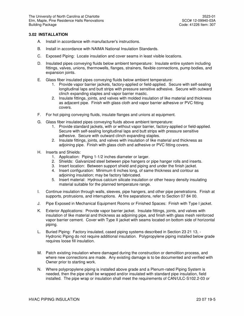
3.02 INSTALLATION
A. Install in accordance with manufacturer's instructions.
B. Install in accordance with NAIMA National Insulation Standards.
C. Exposed Piping: Locate insulation and cover seams in least visible locations.
D. Insulated pipes conveying fluids below ambient temperature: Insulate entire system including fittings, valves, unions, thermowells, flanges, strainers, flexible connections, pump bodies, and expansion joints.
E. Glass fiber insulated pipes conveying fluids below ambient temperature: 1. Provide vapor barrier jackets, factory-applied or field-applied. Secure with self-sealing
longitudinal laps and butt strips with pressure sensitive adhesive. Secure with outward clinch expanding staples and vapor barrier mastic.
2. Insulate fittings, joints, and valves with molded insulation of like material and thickness as adjacent pipe. Finish with glass cloth and vapor barrier adhesive or PVC fitting covers.
F. For hot piping conveying fluids, insulate flanges and unions at equipment.
G. Glass fiber insulated pipes conveying fluids above ambient temperature: 1. Provide standard jackets, with or without vapor barrier, factory-applied or field-applied.
Secure with self-sealing longitudinal laps and butt strips with pressure sensitive adhesive. Secure with outward clinch expanding staples.
2. Insulate fittings, joints, and valves with insulation of like material and thickness as adjoining pipe. Finish with glass cloth and adhesive or PVC fitting covers.
H. Inserts and Shields: 1. Application: Piping 1-1/2 inches diameter or larger. 2. Shields: Galvanized steel between pipe hangers or pipe hanger rolls and inserts. 3. Insert location: Between support shield and piping and under the finish jacket. 4. Insert configuration: Minimum 6 inches long, of same thickness and contour as
adjoining insulation; may be factory fabricated. 5. Insert material: Hydrous calcium silicate insulation or other heavy density insulating
material suitable for the planned temperature range.
I. Continue insulation through walls, sleeves, pipe hangers, and other pipe penetrations. Finish at supports, protrusions, and interruptions. At fire separations, refer to Section 07 84 00.
J. Pipe Exposed in Mechanical Equipment Rooms or Finished Spaces: Finish with Type I jacket.
K. Exterior Applications: Provide vapor barrier jacket. Insulate fittings, joints, and valves with insulation of like material and thickness as adjoining pipe, and finish with glass mesh reinforced vapor barrier cement. Cover with Type II jacket with seams located on bottom side of horizontal piping.
L. Buried Piping: Factory insulated, cased piping systems described in Section 23 21 13, - Hydronic Piping do not require additional insulation. Polypropylene piping installed below grade requires loose fill insulation.
M. Patch existing insulation where damaged during the construction or demolition process, and where new connections are made. Any existing damage is to be documented and verified with Owner prior to starting work.
N. Where polypropylene piping is installed above grade and a Plenum-rated Piping System is needed, then the pipe shall be wrapped and/or insulated with standard pipe insulation, field installed. The pipe wrap or insulation shall meet the requirements of CAN/ULC-S102.2-03 or
The University of North Carolina at Charlotte 3523-01 Elm, Maple, Pine Residence Halls Renovations SCO# 12-09940-03A Building Package Code: 41226 Item: 307
HVAC PIPING INSULATION 23 07 19-6
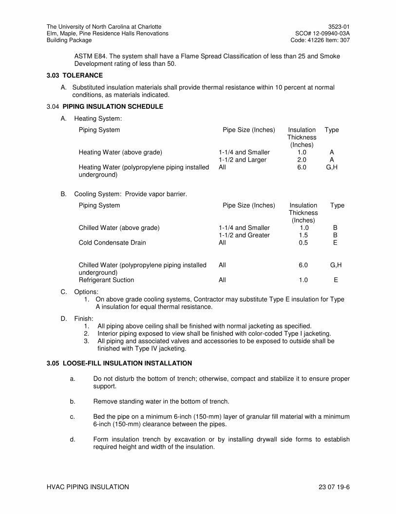
ASTM E84. The system shall have a Flame Spread Classification of less than 25 and Smoke Development rating of less than 50.
3.03 TOLERANCE
A. Substituted insulation materials shall provide thermal resistance within 10 percent at normal conditions, as materials indicated.
3.04 PIPING INSULATION SCHEDULE
A. Heating System:
Piping System Pipe Size (Inches) Insulation Thickness (Inches)
Type
Heating Water (above grade) 1-1/4 and Smaller 1.0 A Heating Water (polypropylene piping installed underground)
1-1/2 and Larger All
2.0 6.0
A G,H
B. Cooling System: Provide vapor barrier.
Piping System Pipe Size (Inches) Insulation Thickness (Inches)
Type
Chilled Water (above grade) 1-1/4 and Smaller 1.0 B 1-1/2 and Greater 1.5 B Cold Condensate Drain All 0.5 E Chilled Water (polypropylene piping installed underground)
All
6.0
G,H
Refrigerant Suction All 1.0 E
C. Options: 1. On above grade cooling systems, Contractor may substitute Type E insulation for Type
A insulation for equal thermal resistance.
D. Finish: 1. All piping above ceiling shall be finished with normal jacketing as specified. 2. Interior piping exposed to view shall be finished with color-coded Type I jacketing. 3. All piping and associated valves and accessories to be exposed to outside shall be
finished with Type IV jacketing. 3.05 LOOSE-FILL INSULATION INSTALLATION
a. Do not disturb the bottom of trench; otherwise, compact and stabilize it to ensure proper support.
b. Remove standing water in the bottom of trench.
c. Bed the pipe on a minimum 6-inch (150-mm) layer of granular fill material with a minimum 6-inch (150-mm) clearance between the pipes.
d. Form insulation trench by excavation or by installing drywall side forms to establish required height and width of the insulation.
The University of North Carolina at Charlotte 3523-01 Elm, Maple, Pine Residence Halls Renovations SCO# 12-09940-03A Building Package Code: 41226 Item: 307
HVAC PIPING INSULATION 23 07 19-7
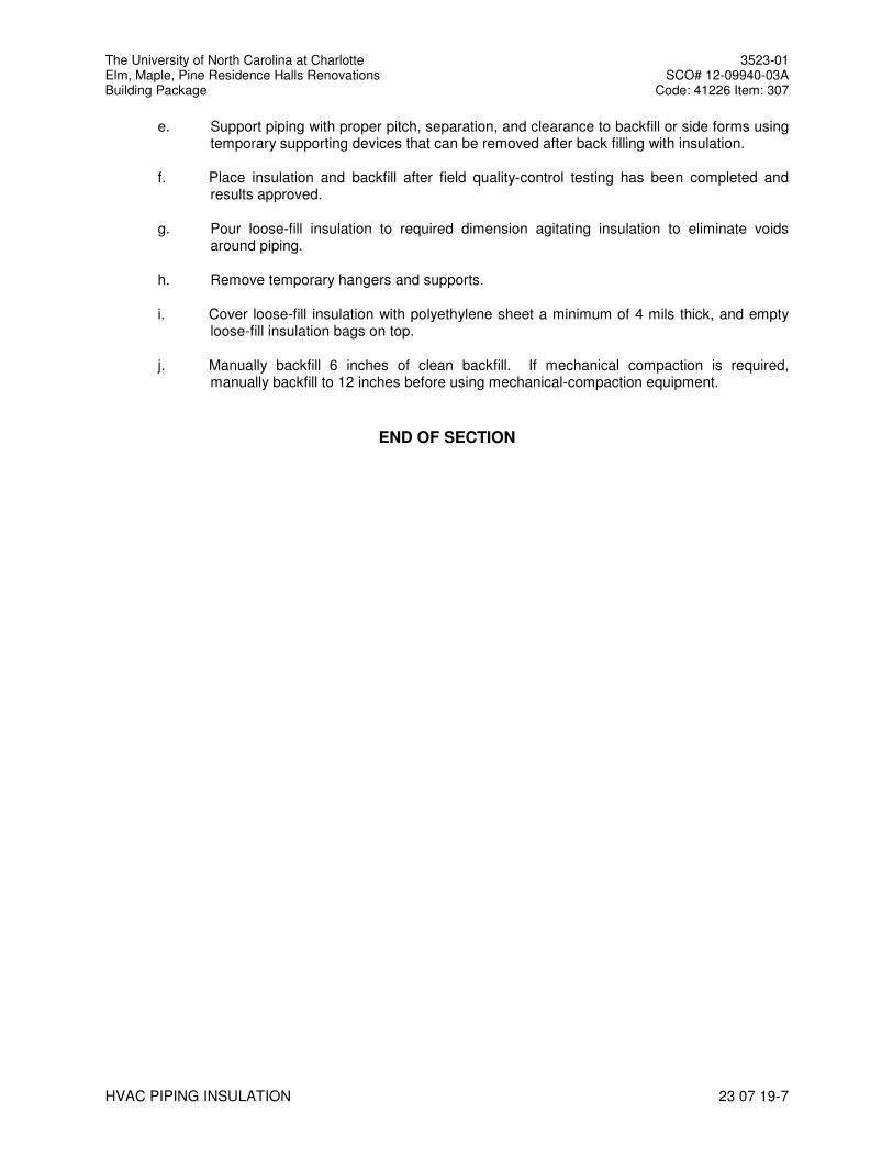
e. Support piping with proper pitch, separation, and clearance to backfill or side forms using temporary supporting devices that can be removed after back filling with insulation.
f. Place insulation and backfill after field quality-control testing has been completed and results approved.
g. Pour loose-fill insulation to required dimension agitating insulation to eliminate voids around piping.
h. Remove temporary hangers and supports.
i. Cover loose-fill insulation with polyethylene sheet a minimum of 4 mils thick, and empty loose-fill insulation bags on top.
j. Manually backfill 6 inches of clean backfill. If mechanical compaction is required, manually backfill to 12 inches before using mechanical-compaction equipment.
END OF SECTION
The University of North Carolina at Charlotte 3523-01 Elm, Maple, Pine Residence Halls Renovations SCO# 12-09940-03A Building Package Code: 41226 Item: 307
INSTRUMENTATION AND CONTROL FOR HVAC 230900 - 1
SECTION 230900
INSTRUMENTATION AND CONTROL FOR HVAC
PART 1 - GENERAL
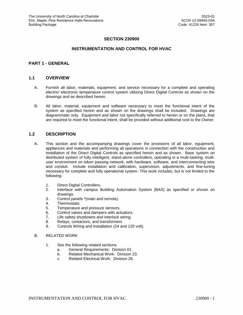
1.1 OVERVIEW
A. Furnish all labor, materials, equipment, and service necessary for a complete and operating electric/ electronic temperature control system utilizing Direct Digital Controls as shown on the drawings and as described herein.
B. All labor, material, equipment and software necessary to meet the functional intent of the system as specified herein and as shown on the drawings shall be included. Drawings are diagrammatic only. Equipment and labor not specifically referred to herein or on the plans, that are required to meet the functional intent, shall be provided without additional cost to the Owner.
1.2 DESCRIPTION
A. This section and the accompanying drawings cover the provisions of all labor, equipment, appliances and materials and performing all operations in connection with the construction and installation of the Direct Digital Controls as specified herein and as shown. Base system on distributed system of fully intelligent, stand-alone controllers, operating in a multi-tasking, multi-user environment on token passing network, with hardware, software, and interconnecting wire and conduit. Include installation and calibration, supervision, adjustments, and fine-tuning necessary for complete and fully operational system. This work includes, but is not limited to the following:
1. Direct Digital Controllers. 2. Interface with campus Building Automation System (BAS) as specified or shown on
drawings. 3. Control panels *(main and remote). 4. Thermostats. 5. Temperature and pressure sensors. 6. Control valves and dampers with actuators. 7. Life safety shutdowns and interlock wiring. 8. Relays, contactors, and transformers 9. Controls Wiring and Installation (24 and 120 volt).
B. RELATED WORK
1. See the following related sections: a. General Requirements: Division 01. b. Related Mechanical Work: Division 23. c. Related Electrical Work: Division 26.
The University of North Carolina at Charlotte 3523-01 Elm, Maple, Pine Residence Halls Renovations SCO# 12-09940-03A Building Package Code: 41226 Item: 307
INSTRUMENTATION AND CONTROL FOR HVAC 230900 - 2
1.3 SYSTEM FEATURES AND ARCHITECTURE
A. UNC Charlotte intends to monitor and control the entire system from an existing browser-based Facility Management System (FMS). A Niagara AX server is located in Physical Plant. It is the intent of the University to integrate this project and all future campus direct digital control systems to this Niagara AX server using the competitive bid process. The entire FMS system including the products and labor detailed in specifications shall be provided by one of the acceptable control system integrators. Provide the appropriate number of Niagara AX based NAC(s) to integrate DDC system as necessary. NAC(s) to be JACE 7 series. Hard drives are not acceptable.
B. The FMS shall be capable of total integration of the facility infrastructure systems with browser access to all system data either locally over a secure Intranet within the campus and by remote VPN access and a standard Web Browser over the Internet. The scope shall include HVAC control and tuning, electrical, gas and water metering, energy management, alarm monitoring, and all trending, reporting and maintenance management functions related to normal building operations all as indicated on the drawings or elsewhere in this specification.
C. Power Fail Protection - All system setpoints, proportional bands, control algorithms, and any other programmable parameters shall be stored such that a power failure of any duration does not necessitate reprogramming the ASC or FPC.
D. The entire Facility Management System (FMS) shall be comprised of a network of interoperable, stand-alone digital controllers communicating via an open protocol communication network to the Niagara AX based UNC Charlotte workstation detailed in section 2.14. The communication from a building to the workstation shall be standardized for maintenance and trouble-shooting considerations and shall be via a Network Area Controller (NAC) over the existing Fiber Optic Network.
E. The intent of this specification is to provide a peer-to-peer networked, stand-alone, distributed control system with the capability to integrate both the ANSI/ASHRAE Standard 135-1995 BACnet and LonWorks technology communication protocols in one open, interoperable system.
F. The existing Niagara AX software system shall employ component-oriented technology (COT) for representation of all data and control devices within the system. In addition, adherence to industry standards including ANSI / ASHRAE™ Standard 135-2010, BACnet and LonMark to assure interoperability between all system components is required. The system supplier must provide a PICS document showing the installed systems compliance level. Minimum compliance is Level 3.
G. The supplied system must incorporate the ability to access all data using Java enabled browsers without requiring proprietary operator interface and configuration programs. An Open DataBase Connectivity (ODBC) or Structured Query Language (SQL) compliant server database is required for all system database parameter storage. This data shall reside on the existing workstation for all database access.
H. A hierarchical topology is required to assure reasonable system response times and to manage the flow and sharing of data without unduly burdening the customer’s internal Intranet network. Systems employing a “flat” single tiered architecture shall not be acceptable.
I. The Campus LAN is an existing fiber optic, 10/100 Megabits/sec Ethernet network supervised by the campus ITS group’. The new FMS shall utilize the network infrastructure to support BACnet, Java, XML, and HTTP for maximum flexibility for integration of building data with enterprise information systems and providing support for multiple Network Area Controllers (NACs), and user workstations. The Ethernet communication protocols must be fully compatible
The University of North Carolina at Charlotte 3523-01 Elm, Maple, Pine Residence Halls Renovations SCO# 12-09940-03A Building Package Code: 41226 Item: 307
INSTRUMENTATION AND CONTROL FOR HVAC 230900 - 3
with the Campus Wide Ethernet communication specifications. The Systems Integrator must coordinate with the Campus Telecommunications Group to attain written approval from the Group to operate on the Campus Wide Network.
J. UNC Charlotte access to the FMS shall be via a standard Internet browser from a remote location utilizing VPN, from a standard browser within the campus network or from a local workstation by direct connection to the Campus LAN. The Control Systems Integrator must provide a connection from every Network Area Controller (NAC) to the campus network to enable this access.
K. The Systems Integrator shall include installation of conduit and thin-wire Ethernet cable from the building’s NAC to the closest telecommunications uniform wiring closet in the building. The Owner shall arrange for an Ethernet connection to be available at a hub within the closest wiring closet. Any material or hardware required for the Ethernet connection at the NAC shall be the responsibility of the Systems Integrator.
L. Provide integration of the new Variable Speed Drives and new Variable Speed Pumping Systems via a Modbus, Lon or BACnet interface provided by the equipment manufacturer. Provide graphics at the FMS to visualize the appropriate information from these systems at the FMS. The cost for all the communication interface hardware and software shall be borne by the successful Systems Integrator except as follows:
1. Chiller Manufacturer shall provide all hardware/software to supply Modbus, BACnet over Ethernet or LonWorks ‘points’ directly from the chiller automation system to a NAC supplied by Control Systems Integrator. Integrator shall accept any of these protocols and integrate this information into the FMS as appropriate.
2. New Variable Speed Drive systems manufacturer shall provide a Modbus , BACnet over Ethernet or LonWorks Interface to the NAC.
1.4 SYSTEM PROGRAMMING
A. The system supplied by the SI must be programmed using a palette of control, application, and graphical components provided to enable the creation of all applications and user interface screens. Applications are to be created by selecting the desired control components from the palette, dragging or pasting them on the screen, and “wiring” them together using a built in graphical connection tool. All completed applications must be stored in the UNC Charlotte AX Workstation software palette for future use by any future SI selected by UNC Charlotte. Graphical User screens are created in the same fashion. Data for the user screens is obtained by graphically linking the graphical components to the application components to provide “real-time” data updates. Any real-time data value or component property may be connected to display its current value on a user screen. Systems requiring separate software tools or processes to create applications and user interface screens shall not be acceptable.
B. Programming Methods:
1. Provide the capability to copy components from the supplied palette, or from a user-defined palette to the user’s application. Components shall be linked by a graphical linking scheme by dragging a link from one component to another. Component links will support one-to-one, many-to-one, or one-to-many relationships. Linked components shall maintain their connections to other components regardless of where they are positioned on the page and shall show link identification for links to components on other pages for easy identification. Links will vary in color depending on the type of link; i.e., internal, external, hardware, etc.
The University of North Carolina at Charlotte 3523-01 Elm, Maple, Pine Residence Halls Renovations SCO# 12-09940-03A Building Package Code: 41226 Item: 307
INSTRUMENTATION AND CONTROL FOR HVAC 230900 - 4
2. Configuration of each component will be done through the component’s property sheet using fill-in the blank fields, list boxes, and selection buttons. Requiring the use of custom programming, scripting language, or a manufacturer-specific procedural language for every component configuration will not be accepted.
3. The software shall provide the ability to view the logic in a monitor mode. When on-line, the monitor mode shall provide the ability to view the logic in real time for easy diagnosis of the logic execution. When off-line (debug), the monitor mode shall allow the user to set values to inputs and monitor the logic for diagnosing execution before it is applied to the system.
4. All programming shall be done in real-time. Systems requiring the uploading, editing, and downloading of database component s shall not be allowed.
5. The system shall support component duplication within a customer’s database. An application, once configured, can be copied and pasted for easy re-use and duplication. All links, other than to the hardware, shall be maintained during duplication.
1.5 GRAPHICAL USER INTERFACE SOFTWARE
A. UNC Charlotte has licensed a Niagara AX Supervisor for the development of their FMS logic and graphics. This user interface shall allow, with proper password access, full interaction with the system including, but not limited to, viewing and modifying data, database administration, configuration of communications parameters, password and security administration, programming and configuration of components, receipt, routing and acknowledgement of alarms, and development of graphic screens.
B. The user interface shall employ browser-like functionality for ease of navigation. It shall include a tree view for quick viewing of, and access to, the hierarchical structure of the database. In addition, menu-pull downs, and toolbars shall employ buttons, commands and navigation techniques similar to those in a commercially available Web Browser. These shall include, but are not limited to, forward/backward buttons, home button, and a context sensitive locator line (similar to a URL line), that displays the location and the selected component identification. 1. Graphic screens shall be developed using any drawing package capable of generating a
.GIF, .BMP, or .JPG file format. Use of proprietary graphic file formats shall not be acceptable. In addition to, or in lieu of, a graphic background, the user interface shall support the use of scanned pictures.
2. Graphics developed for the user interface shall be capable of being used by a standard Web Browser client, without the need to develop additional graphic screens specifically for the Web Browser.
3. Graphic screens shall have the capability to be overlaid with text, real-time values, command and adjust, animation, color spectrum, logs, graphs, HTML document links, and schedule graphic components, as well as links to other graphic screens.
4. Modifying common application components, such as schedules, calendars, and set points shall be accomplished in a graphical manner.
5. Schedule times will be adjusted using a graphical slider, without requiring any keyboard entry from the operator.
6. Holidays shall be set by using a graphical calendar, without requiring any keyboard entry from the operator.
7. Commands issued to start and stop binary components shall be done by right-clicking the selected component and selecting the appropriate command from the pop-up menu. No entry of text shall be required.
8. Adjustments to analog components, such as set points, shall be done by right-clicking the selected component and using a graphical slider to adjust the value. No entry of text shall be required.
The University of North Carolina at Charlotte 3523-01 Elm, Maple, Pine Residence Halls Renovations SCO# 12-09940-03A Building Package Code: 41226 Item: 307
INSTRUMENTATION AND CONTROL FOR HVAC 230900 - 5
1.6 FMS GRAPHICS
A. The successful SI will be responsible for building new graphics from existing templates. The graphics shall be coordinated with UNC Charlotte staff and shall be similar to standards developed in previous Niagara systems. The Integrator will be responsible for creating web pages within the supplied system with new information, links, etc. as buildings or systems are added. It is the SI’s responsibility to remain knowledgeable about the University’s standard FMS procedures, web page style and existing palette of components prior to bidding the next project. A pre-engineering meeting shall be arranged between the systems integrator and the owner to discuss each project specifically before engineering and graphics developments begin. The following are mandatory requirements for each site.
1. Each graphics screen shall include the approved UNCC look and links across the top per the graphics template.
2. Deleted (reference to campus map). 3. The systems integrator is responsible for providing a link to the control drawings (.dwf
format) for each associated piece of equipment. A button for control drawings shall be located on the UNCC frame navigation bar. On integration projects, where existing controls exist, UNCC shall be responsible for providing the control drawings (.dwf format) to the systems integrator. On new projects the systems integrator shall be responsible for providing the as-built control drawings. Note the system shall be engineered in such a way that the control drawings will be accessible with a standard browser-utilizing WHIP! or Volo View Express (Auto-Cad will not be required).
4. The systems integrator is responsible for providing a link to the operating and maintenance manuals for each major piece of equipment (Chiller, Boiler, Pumps, VFDs). This link shall be located on the graphic for each piece of equipment, per the template. UNCC will provide the O&M data (.pdf format) and shall install it on the UNCC FMS network server for use by the systems integrator.
5. All graphics shall have a resolution of 1280 by 800 pixels. (Confirm with owner before graphics development.)
6. All graphics shall be designed for viewing using Internet Explorer 8.0 or whatever may be UNCC standard at the time of deployment (not at time of submittals).
7. All graphics shall be standard from the UNCC FMS graphics palette. 8. Any custom graphics that do not originate from the UNCC FMS graphics palette will require
UNCC approval prior to deployment. The UNCC approved graphics will be installed in the UNCC FMS graphics palette located on the hard drive of the UNCC server by the systems integrator for future use as needed.
9. Any graphics work developed and provided by the Systems Integrator for any UNCC project shall become the property of UNCC and shall be available for use by any other Systems Integrator on a UNCC project. (UNCC wishes to reuse and standardize on graphics and ideas that work well).
10. The systems integrator shall submit to UNCC (2) copies of a graphical proposal. The graphical proposal shall include written and graphical representation of proposed Web-based, FMS navigational user interface including screen shots to be used for the proposed project. Software graphical proposals viewable with a browser, delivered on compact disc or available via the Internet are acceptable.
1.7 WEB BROWSER CLIENTS
A. The system shall be capable of supporting an unlimited number of clients using a standard Web Browser such as Internet Explorer™ or Netscape Navigator™. Systems requiring additional software resident on the client machine or manufacture-specific browsers shall not be acceptable.
The University of North Carolina at Charlotte 3523-01 Elm, Maple, Pine Residence Halls Renovations SCO# 12-09940-03A Building Package Code: 41226 Item: 307
INSTRUMENTATION AND CONTROL FOR HVAC 230900 - 6
B. The Web Browser client shall support, at a minimum, the following functions: 1. User log-on identification and password shall be required. If an unauthorized user
attempts access, a blank web page shall be displayed. Security using Java authentication techniques to prevent unauthorized access shall be implemented.
2. Graphical screens developed for the GUI shall be the same screens used for the Web Browser client. Storage of the graphical screens shall be in the system, without requiring any graphics to be stored on the client machine. Systems that require graphics storage on each client are not acceptable.
3. Depending on user access privileges, the user shall be able to view data, modify and command components such as start/stop, and adjust set points. In addition, users can be provided with the ability to view logs and view and acknowledge alarms.
4. The system shall provide the capability to specify a user’s (as determined by the log-on user identification) home page. The capability to limit the user to just their home page shall be provided. From the home page, links to other views, or pages in the system shall be possible.
5. Graphic screens on the Web Browser client shall support hypertext links to other Web pages on other Internet or Intranet sites.
1.8 COMPONENT LIBRARIES
A. A standard palette of components shall be included by UNC Charlotte for development and setup of application logic, user interface displays, system services, and communication networks. The successful Systems Integrator may be required to develop new components to meet the intent of this specification. Any new components created must be stored in the UNC Charlotte component palette for future use. It is the responsibility of the Systems Integrator to verify what components exist in the UNC Charlotte palette prior to bidding this project.
B. The components in this palette shall be capable of being copied and pasted into the user’s database and shall be organized according to their function. In addition, the user shall have the capability to group components created in their application and store the new instances of these components in a user-defined palette.
C. The successful systems integrator shall update the UNC Charlotte standard palette specified here to provide new or updated components and applications as they are developed by the software manufacturer.
D. The Systems Integrator shall be responsible for timely verification that the UNC Charlotte palette includes services and components to support the particular LonWorks and BACnet devices that the SI proposes to bid and install. If the components do not exist or will not exist in time to install this particular project, the SI must utilize a component that does exist.
1.9 LOAD CONTROL PROGRAMS
A. General: Support inch-pounds and S.I. metric units of measurement.
B. Automatic Time Scheduling:
1. Self-contained programs for automatic start/stop. 2. Support up to seven (7) normal day schedules, seven (7) "special day" schedules and
two (2) temporary day schedules. 3. Special days schedule shall support up to 30 unique date/duration combinations. 4. Any number of loads assigned to any time program; each load can have individual time
program.
The University of North Carolina at Charlotte 3523-01 Elm, Maple, Pine Residence Halls Renovations SCO# 12-09940-03A Building Package Code: 41226 Item: 307
INSTRUMENTATION AND CONTROL FOR HVAC 230900 - 7
5. Each load assigned up to 8 time schedules per day with 1 minute resolution. 6. Time schedule operations may be:
a. Start. b. Optimized start. c. Stop. d. Optimized stop.
7. Minimum of 30 holiday periods up to 365 days in length may be specified for the year. 8. Controller shall be able to account for daylight savings time.
C. Start/Stop Time Optimization:
1. Perform optimized start/stop as function of outside conditions, inside conditions, or both. 2. Adaptive and self-tuning, adjusting to changing conditions unattended. Set Inactive. 3. For each point under control, establish and modify:
a. Occupancy period.
D. Calculated Points: Define calculations and totalization computed from monitored points (analog/digital points), constants, or other calculated points.
1. Employ arithmetic, algebraic, Boolean, and special function operations. 2. Treat calculated values like any other analog value, use for any function that a "hard
wired point" might be used.
E. Event Initiated Programming: Event may be initiated by any data point, causing series of controls in a sequence.
1. Define time interval between each control action. 2. Output may be analog value. 3. Provide for "skip" logic. 4. Verify completion of each action.
F. Direct Digital Control: Each control unit shall provide Direct Digital Control software so that the operator may customize control strategies and sequences of operation by defining the appropriate control loop algorithms and choosing the optimum loop parameters.
1. Control loops: Defined using "modules" that are analogous to standard control devices. 2. Output: Paired or individual digital outputs for pulse-width modulation, and analog
outputs, as required. 3. Firmware:
a. PID with analog or pulse-width modulation output. b. Floating control with pulse-width modulated outputs. c. Two-position control. d. Primary and secondary reset schedule selector. e. Hi/Lo signal selector. f. Digital output. g. Time delay function with delay before break, delay before make and interval time
capabilities.
4. Direct Digital Control loops: Downloaded upon creation or on operator request. On sensor failure, program shall execute user defined failsafe output.
5. Display: LCD type.
The University of North Carolina at Charlotte 3523-01 Elm, Maple, Pine Residence Halls Renovations SCO# 12-09940-03A Building Package Code: 41226 Item: 307
INSTRUMENTATION AND CONTROL FOR HVAC 230900 - 8
6. Fine Tuning Direct Digital Control PID or floating loops:
a. Display Information: 1) Control loop being tuned. 2) Input (process) variable. 3) Output (control) variable. 4) Setpoint of loop. 5) Proportional band. 6) Integral (reset) interval. 7) Derivative (rate) interval.
b. Display Format: LCD type.
1.10 HVAC CONTROL PROGRAMS
A. General: Identify each HVAC Control System.
B. Optimal Run Time: 1. Control start-up and shutdown times of HVAC equipment for cooling. 2. Base on occupancy schedules, outside air temperature, seasonal requirements. 3. Operator commands:
a. Define term schedule. b. Lock/unlock program.
4. Control Summary:
a. HVAC Control system begin/end status. b. PRODUCTSOptimal run time lock/unlock control status. c. Cooling mode status. d. Optimal run time schedule. e. Start/Stop times. f. Optimal run time system normal start times. g. Occupancy and vacancy times.
5. HVAC Point Summary:
a. Control system identifier and status. b. Point ID and status. c. Outside air temperature point ID and status. d. Period start.
1.11 PROGRAMMING APPLICATION FEATURES
A. Alarm Messages:
1. Output assigned alarm on LCD display; low/high and status alarms.
B. Weekly Scheduling:
1. Automatically initiate equipment or system commands, based on preselected time schedule for points specified.
The University of North Carolina at Charlotte 3523-01 Elm, Maple, Pine Residence Halls Renovations SCO# 12-09940-03A Building Package Code: 41226 Item: 307
INSTRUMENTATION AND CONTROL FOR HVAC 230900 - 9
2. Provide program times for each day of week, per point. 3. Automatically generate alarm output for points not responding to command. 4. Provide for holidays. 5. Operator commands:
a. System logs and summaries. b. Optimal run timStart/stop point. c. Add, delete, or modify analog limits and differentials. d. Adjust point operation position. e. Change point operational mode. f. Open or close point. g. Begin or end point totalization. h. Modify totalization values and limits. i. Access or secure point. j. Begin or end HVAC or load control system. k. Modify load parameter.
6. Output Summary: Listing of programmed function points, associated program times, and respective day of week programmed points by software groups or time of day.
C. Interlocking:
1. Permit events to occur, based on changing condition of one or more associated master points.
2. Binary contact, high/low limit of analog point or computed point shall be capable of being utilized as master. Same master may monitor or command multiple slaves.
3. Operator Commands: a. Define single master/multiple master interlock process. b. Define logic interlock process. c. Lock/unlock program. d. Enable/disable interlock process.
1.12 UTILITY MONITORING SOFTWARE INTEGRATION
A. The University of North Carolina at Charlotte is using PeriscopeTM by ActiveLogix as its energy profiling/analysis software tool. The PeriscopeTM software is currently loaded on the FMS server. The Systems Integrator is responsible for providing for providing trends for integration into PeriscopeTM . The Systems Integrator will provide an energy/utility dashboard for this project using the PeriscopeTM software.
B. System shall provide browser access to unit controllers and associated setpoints and tuning parameters. The Building Automation System shall be comprised of BACnet or LonMark/LonTalk controllers. Should the NAC network connection be interrupted, the DDC components shall continue to provide local control using the last known state of any global variables (OA temperature, Demand Value, Price of Energy, etc.) It shall be the DDC contractor’s responsibility to effectively design and program standalone control while coordinating the required DDC integration and communication to the NAC.
1.13 SOFTWARE LICENSE AGREEMENT
A. The Owner has signed a software and firmware licensing agreement for the FMS software. Such license shall grant use of all programs and application software to Owner as defined by the manufacturer's license agreement, but shall protect manufacturer's rights to disclosure of
The University of North Carolina at Charlotte 3523-01 Elm, Maple, Pine Residence Halls Renovations SCO# 12-09940-03A Building Package Code: 41226 Item: 307
INSTRUMENTATION AND CONTROL FOR HVAC 230900 - 10
trade secrets contained within such software. Systems Integrators that participate in the integration of UNC Charlotte’s direct digital control systems must:
1. Be certified in the use, application and service of Niagara AX software and shall provide documentation from the manufacturer’s training center as such. However, certification in the above does not automatically qualify an integrator to bid on proposed UNC Charlotte projects. Only approved integrators listed in this specification are eligible to participate in the project.
2. Agree to use on any UNC Charlotte project any application standards, html pages, graphics templates, etc. developed by or for UNC Charlotte for the purpose of digital control, scheduling, alarming, graphics, etc.
3. Agree that the application standards, html pages, graphics templates, etc. developed by or for UNC Charlotte are the property of UNC Charlotte (subject to the manufacturer’s license agreement) and shall not be reproduced, etc. for use on any other customer, project, etc. without the expressed written permission of the UNC Charlotte facilities staff.
4. Agree that certification on the manufacturer’s software does not guarantee continued participation in UNC Charlotte’s FMS projects.
5. Agree to provide UNC Charlotte’s staff with the highest level of administrative password. 6. Agree that UNCC staff and other Systems Integrators can use the onsite UNCC software
tools to modify NACs, license files, passwords, provide software maintenance, etc after warranty period expires.
B. The owner requires that all Niagara Ax based software and hardware on this project have the following Niagara Information Compatibility Statement (NICS). The Existing Niagara AX Server complies with the requirements below. Organizations without the NICS below shall not be allowed to bid.
1. Brand ID = Vykon 2. Station Compatibility In = * 3. Station Compatibility Out = * 4. Tool Compatibility In = * 5. Tool Compatibility Out = *
1.14 ACCEPTABLE CONTROL SYSTEM INTEGRATORS/CONTROL SYSTEM MANUFACTURES:
A. Manufacturers:
1. Hoffman Building Technologies (using Alerton Controls native BACnet controllers). 2. Schneider Electric Controls (using Invensys I/A series Lonworks or approved BACnet). 3. United Automation Corporation (using Honeywell Lonworks Controllers). 4. Mechanical Systems and Services (using Honeywell Lonworks Controllers). 5. Johnson Controls (using open protocol BACnet controllers and an approved Tridium
systems integrator).
B. Application engineers working on this project shall be required to be certified in Niagara AX and certified by the DDC controls manufacturer to perform all engineering services. The Systems shall be installed by trained mechanics either in direct employ of Systems Integrator or by subcontractors who are under direct supervision of Systems Integrator’s field representative. Submit resumes of application engineers and field supervisors to be assigned to this project within 30 days after contract award. Application engineers shall have prior experience with at least 2 similar types of projects. Engineer reserves right to exclude any engineers or field supervisors whose past experience is not sufficient to meet the needs of the project.

The University of North Carolina at Charlotte 3523-01 Elm, Maple, Pine Residence Halls Renovations SCO# 12-09940-03A Building Package Code: 41226 Item: 307
INSTRUMENTATION AND CONTROL FOR HVAC 230900 - 11
C. Systems Integrators labor shall include, but is not limited to:
1. Engineering services to size all valve and dampers based on design criteria specified. 2. Engineering services to produce all submittals requested and working construction
drawings and record drawings as specified here within. 3. Engineering services for all software programming required. 4. Engineering services for all software programming specified. 5. Project management services with single point contact to coordinate all construction
related activities. 6. Field mechanics for installation of pneumatic tubing and related control devices. 7. Field mechanics for installation of control wiring and related control devices. 8. Field technicians to start-up, calibrate, adjust and tune all control loops per specifications. 9. Field technicians to perform system checkout, testing and complete required reports. 10. Full time field supervisor during controls installation and start-up. 11. Field technicians to assist testing and balancing contractor in adjusting controls and
determining set points related to his scope of work. 12. Field representatives and/or classroom instructors to provide Owner training as specified.
D. Controls System Integrator shall be responsible for complete installation of all control devices, except as noted, wiring and pneumatic terminations at panel locations to accomplish control sequences specified in this project manual or on drawings. System Integrator is also responsible for any additional instrumentation described in any point schedules found in this contract document, which may not be directly related to any specified control sequences.
1.15 SUBMITTALS
A. Submittals shall be coordinated through the control systems integrator provided as a part of this controls contract. This contractor shall incorporate DDC submittals and all other associated Ethernet or serial communication devices not provided by this contractor into the electronic submittals. This contractor shall be responsible for verification that the sequence of operations is inclusive of all requirements and properly coordinates the division of work. Submittal requirements include:
1. Product Data:
a. Include manufacturer's technical literature for each control device. Indicate dimensions, capacities, performance characteristics, electrical characteristics, finishes for materials, and installation and startup instructions for each type of product indicated.
2. Shop Drawings:
a. Submit manufacturer’s printed product data sheets for all control devices and all materials listed in bill of material in control drawings. Organize sheets in order of model number, alphabetically, then numerically. If more than 20 product data sheets are submitted, provide front index and tabs for logical groups of devices.
b. Submit control drawings with a front sheet index for projects with more than 10 control drawing sheets.
c. Overall system/network architecture drawings: Provide schematic drawing showing relationship of each controller, control panel or other network devices relative to each other, label room location of each device, number and indicate model number of each device, indicate network types and general cabling routing.
d. Schematic Control Drawings: Include graphic representation of systems with all major inline components to properly locate all control devices. Identify controlled
The University of North Carolina at Charlotte 3523-01 Elm, Maple, Pine Residence Halls Renovations SCO# 12-09940-03A Building Package Code: 41226 Item: 307
INSTRUMENTATION AND CONTROL FOR HVAC 230900 - 12
devices with their software designation on drawings, including unique valve and damper tag numbers.
e. Control Logic Drawings: Include graphical programming logic drawings with all controllers and associated parameters, logic, inputs, outputs and control loops.
f. Control Points List: As part of Schematic Control Drawings (see #4 above), include tabular representation of all points associated with a given DDC controller (hardware and software points) and provide the following information about each point:
1) Is point exposed on graphic page? 2) Is point commandable/adjustable by UNCC from graphic? 3) Is point scheduled? 4) Is point trended? How many samples? Is trend archived to server? Is trend
archived to PeriscopeTM? 5) Is point alarmed? What are high/low alarm limits? 6) What are point units (i.e. DEG F, etc)?
g. Detailed wiring and piping diagrams showing point to point hookup details of all transducers, relays, outputs, inputs and subsystem components. Label all pneumatic lines and control wires with field ID numbers/colors.
h. Bill of material identifying actual product model number used for each control device for each schematic control drawing.
i. Sequence of Operation: Verbally describe each control sequence indicating method of control. Identify sensors, controllers and actuators used with references to tag number of the controlled device. Include set points and offsets of each control loop.
j. Wiring Diagrams: Power, signal, and control wiring. Differentiate between manufacturer-installed and field-installed wiring.
k. Schedule of dampers and valves including size, leakage, and flow characteristics.
1.16 COMPLETION CHECKLIST
A. Submit with shop drawings a detailed completion checklist including written procedures for adjusting and calibrating each type of controller, instrument and sensor. Checklist shall also include step-by-step written procedure to functionally test each type of control loop or logic sequence. The Engineer reserves right to request modifications to any procedure which is incomplete or not adequate to prove system performance.
B. Check list to include references to the following additional requirements:
1. Instruments and sensors shall be calibrated by comparison to known device, which is traceable to National Institute of Standards and Testing.
2. Check each point for calibration, connection to correct control loop and that limit and alarm values are properly set.
3. Transducers and other output devices shall be properly zeroed, and calibrated at both minimum and maximum output. Control contractor shall coordinate with testing, adjusting and balancing contractor to determine flows at minimum and maximum conditions for each device.
4. Tune control loops to maintain controlled process variable at set point throughout the year without cycling or requiring modifications to control system. AUTO TUNING IS NOT ACCEPTABLE.
5. Performance tests of all analog control loops shall be performed by changing set point and verify that sequence can come into stable equilibrium within reasonable time period
The University of North Carolina at Charlotte 3523-01 Elm, Maple, Pine Residence Halls Renovations SCO# 12-09940-03A Building Package Code: 41226 Item: 307
INSTRUMENTATION AND CONTROL FOR HVAC 230900 - 13
which is appropriate for that sequence. Use load changes for all pressure and flow control loops.
6. System performance shall be documented via 48 hour printed trend log report of actual output performance versus set point.
7. Perform tests of discrete control loops by adjusting set point and verifying sequence action.
8. All alarms, including network failures, to be tested for each controller and device connected to network, and ensure that alarms are properly acknowledged at control panel.
1.17 EXTENDED SERVICE AGREEMENT
A. Control manufacturer shall, upon completion of warranty period, make available to Owner annual service agreement covering all labor and material required to effectively maintain control system after warranty period. Owner reserves rights to accept or reject any such offers and to cancel ongoing agreement with 30 day written notice.
1.18 SUBMITTALS FOR INFORMATION
A. Manufacturer's Instructions: Indicate manufacturer's installation instructions for all manufactured components.
1.19 SUBMITTALS AT PROJECT CLOSEOUT
A. Project Record Documents: Record actual locations of control components, including control units, thermostats, and sensors. 1. Revise shop drawings to reflect actual installation and operating sequences. 2. Include data specified in “Submittals” in final “Record Documents” form.
B. Provide 3 hard copies and 1 electronic copy of O&M Manuals. Provide drawings in ACAD format.
C. Operation and Maintenance Data:
1. Include interconnection wiring diagrams complete field installed systems with identified and numbered, system components and devices.
2. Include step-by-step procedures indexed for each operator function. 3. Include inspection period, cleaning methods, cleaning materials recommended, and
calibration tolerances. 4. Calibration records and list of set points.
1.20 QUALITY ASSURANCE
A. The Manufacturer of the interoperable controllers shall provide documentation supporting compliance with ISO-9001 (Model for Quality Assurance in Design/Development, Production, Installation and Servicing). Product literature provided by the interoperable controller manufacturer shall contain the ISO-9001 Certification Mark from the applicable registrar.
The University of North Carolina at Charlotte 3523-01 Elm, Maple, Pine Residence Halls Renovations SCO# 12-09940-03A Building Package Code: 41226 Item: 307
INSTRUMENTATION AND CONTROL FOR HVAC 230900 - 14
1.21 WARRANTY AND SERVICE
A. The controls contractor shall warrant the system to be free from defects in material and workmanship for a period of two (2) year from the date of completion and acceptance of the work by the owner. Any defects shall be repaired or replaced, including materials and labor at no cost to the owner.
B. The controls contractor shall provide two (2) years of maintenance service for the controls system to begin concurrently with the 1st year of warranty. Service shall include inspection and adjustment of all operating controls and components. The service shall be performed every 6 months and documentation of service shall be provided to Facilities Operations.
1.22 EXTRA MATERIALS
A. Furnish the following extra materials to Facilities Operations at completion:
1. 2 water temperature sensors. 2. 1 space humidity type sensor. 3. 1 duct type humidity sensor. 4. 2 zone thermostats. 5. 2 zone carbon dioxide monitors. 6. 2 VAV box DDC Controllers. 7. 1 duct type temperature sensor.
1.23 COORDINATION
A. This contractor shall coordinate with the other contractors as required to produce workable, controllable systems. Generally, all control and monitoring equipment shall be furnished and installed by this contractor unless otherwise noted. The controls contractor may subcontract the wiring of direct digital controls system. Specific examples of coordination and cooperation include:
1. Smoke detection system shall be furnished and wired to the fire alarm system by the electrical subcontractor.
2. Duct mounted smoke detectors shall be installed by the mechanical subcontractor. The electrical contractor shall provide contacts for air handler shut down at the fire alarm panel. This DDC contractor shall wire from these contacts and incorporate into the air handler controls.
1.24 APPLICATION SOFTWARE DOCUMENTATION
A. Contractor shall provide a copy of all BACnet or Lonworks .xif files and system databases on Compact disk.
The University of North Carolina at Charlotte 3523-01 Elm, Maple, Pine Residence Halls Renovations SCO# 12-09940-03A Building Package Code: 41226 Item: 307
INSTRUMENTATION AND CONTROL FOR HVAC 230900 - 15
PART 2 - PRODUCTS
2.1 MATERIALS
A. All materials and equipment used shall be standard components and regularly manufactured for this application. All systems and components shall have been thoroughly tested and proven in actual use.
2.2 STATEMENT OF COMPLIANCE WITH SPECIFICATIONS
A. Bidders shall submit statement of compliance with the bid package, for review by the Owner's authorized representatives, a written line by line statement of compliance to the specifications related to the automatic control and building automation system.
2.3 EQUIPMENT
A. Network Area Controller (NAC)
1. The NAC shall provide the interface between the Campus LAN and the field controllers. NACs shall be based on Niagara AX software and shall be provided with the OBIX driver. Provide the following NICS in each NAC:
a. Brand ID = Vykon b. Station Compatibility In = * c. Station Compatibility Out = * d. Tool Compatibility In = * e. Tool Compatibility Out = *
2. The NAC shall provide multiple user access to the system and support for ODBC or SQL. An embedded database resident on the NAC must be an ODBC-compliant database or must provide an ODBC data access or must provide an ODBC data access mechanism to read and write data stored within it. A minimum offering would be the documentation of database schemes to allow users to read/write data into other applications using appropriate ODBC syntax.
3. The NAC must provide all tools for Java enabled Web browser access via the Intranet/Internet.
4. Event alarm Notification and Actions:
a. The NAC shall provide alarm recognition, storage; routing, management, and analysis to supplement distributed capabilities of equipment or application specific controllers. Object alarm properties shall conform to the alarm properties as defined in the BACnet specification.
b. The NAC shall be able to route any alarm condition to any defined user location whether connected to a local network or remote via dial-up, telephone connection, or wide-area network.
c. Alarms shall have the capability to be routed to e-mail messages and paging services that support receipt of e-mail messages.
d. The NAC shall provide a timed (scheduled) routing of alarms by component, group or code.
e. The NAC shall include a master clock service for its subsystems and provide time synchronization for all distributed controllers. The NAC shall also be programmed
The University of North Carolina at Charlotte 3523-01 Elm, Maple, Pine Residence Halls Renovations SCO# 12-09940-03A Building Package Code: 41226 Item: 307
INSTRUMENTATION AND CONTROL FOR HVAC 230900 - 16
to accept time synchronization messages from trusted precision Atomic Internet Clock sites to update its master clock time.
5. Data Collection and Storage:
a. The NAC shall be provided with the ability to collect data for any property of any component and store this data for future use.
b. The data collection shall be performed by a log component that shall have, at a minimum, the following configurable properties:
c. Designating the log as interval or deviation. d. For interval logs, the component shall be configured for time of day, day of week
and the sample collection interval. e. For deviation logs, the component shall be configured for the deviation of a
variable to a fixed value. This value, when reached, will initiate logging of the component.
f. For all logs, provide the ability to set the maximum number of data stores and to set whether the log will stop collecting when full, or rollover the data on a first-in, first-out basis.
B. Interoperable Lonmark Controller (ILC):
1. Controls shall be microprocessor based Interoperable LONMARK Controllers (ILC), bearing the applicable LONMARK interoperability logo on each product delivered. ILCs shall be provided. ILCs shall be based on the Echelon Neuron 3150 microprocessor working from software program memory, which is physically located in the ILC. The application control program shall be resident within the same enclosure as the input/output circuitry, which translates the sensor signals.
2. To simplify controls and mechanical service troubleshooting, the ILC shall be mounted directly in the control compartment of the unitary system. The ILC shall be provided with a sheet metal or polymeric enclosure that is constructed of material allowing for the direct mounting within the primary air stream, as defined by UL-465. The direct mounting shall allow all controls maintenance and troubleshooting to be made while at the unitary equipment.
3. The ILCs shall communicate with the NAC at a baud rate of not less than 78.8K baud. The ILC shall provide LED indication of communication and controller performance to the technician, without cover removal.
4. The ILCs shall be fully supported and communicate with the FMS Graphical User Interface (GUI).
5. The ILC Sensor shall connect directly to the ILC and shall not utilize any of the I/O points of the controller. The ILC Sensor shall provide a two-wire connection to the controller that is polarity and wire type insensitive. The ILC Sensor shall provide a communications jack for connection to the LON communication trunk to which the ILC controller is connected. The ILC Sensor, the connected controller, and all other devices on the LON bus shall be accessible by the POT.
6. All input/output signals shall be directly hardwired to the ILC. For all non-VAV terminal applications, a minimum of two input points of the ILC shall employ a universal configuration that allows for flexibility in application ranging from dry contact, resistive, to voltage/current sourced inputs. If universal points are not available, a minimum of two input points (each) of the dry contact, resistive and analog voltage/current types must be provided on every controller. The outputs of the ILC shall be of the relay and universal analog form. All digital outputs shall be relay type. ILC devices utilizing non-relay outputs shall provide an interface relay for all points. All analog outputs shall be programmable for their start points and span to accommodate the control devices. Configuration of all I/O points shall be accomplished without physical hardware jumpers, switches or settings. Troubleshooting of input/output signals shall be easily executed
The University of North Carolina at Charlotte 3523-01 Elm, Maple, Pine Residence Halls Renovations SCO# 12-09940-03A Building Package Code: 41226 Item: 307
INSTRUMENTATION AND CONTROL FOR HVAC 230900 - 17
with the POT or a volt-ohm meter (VOM). All I/O points shall be utilized by the local ILC or shall be available as I/O points for other controllers throughout the network.
7. All ILCs shall be fully application programmable and shall at all times maintain their LONMARK certification. Controllers offering application selection only (non-programmable), require a 10% spare point capacity to be provided for all applications. All control sequences within or programmed into the ILC shall be stored in non-volatile memory, which is not dependent upon the presence of a battery, to be retained.
8. The ILC shall be provided with the ability to interface with the POT. The interface port shall be provided at the wall sensor or within the unitary equipment, as specified on the plans. The interface port shall allow the POT to have full functionality as described in POT section of this specification.
C. Interoperable Digital Controller (IDC):
1. Controls shall be microprocessor based Interoperable LonWorks Digital Controllers (IDC), providing interoperability with all LONMARK and LonWorks devices. IDCs shall be provided for any equipment applications as required, as shown on the drawings. IDCs shall be based on the Echelon Neuron Hosted microprocessor architecture, working from software program memory that is physically located in the IDC. The application control program shall be resident within the same enclosure as the input/output circuitry, which translates the sensor signals.
2. All IDCs shall be fully application programmable utilizing graphical components. All control sequences programmed into the IDC shall be stored in non-volatile memory, which is not dependent upon the presence of a battery, to be retained. Systems that only allow selection of sequences from a palette or table are not acceptable.
3. The IDC shall be provided with the ability to interface with the POT. The interface port shall allow the POT to have full functionality as described in POT section of this specification. Through the interface port all IDC devices on the LON bus shall be accessible by the POT.
4. The IDCs shall communicate with the NAC at a baud rate of not less than 78.8K baud. The IDC shall have as a minimum ambient operating temperature range of 32 to 122 degrees Fahrenheit.
5. The IDC shall be fully supported by the Graphical User Interface (GUI). 6. All input/output signals shall be directly hardwired to the IDC. All controllers shall employ
a universal input configuration that allows for flexibility in application ranging from dry contact, resistive and voltage/current-source inputs. If universal points are not available, a minimum of one spare input point (each) of the dry contact, resistive and analog voltage/current types must be provided for each input point utilized. IDC devices shall provide digital and analog output types and quantities consistent with the requirements of the application requirements. Troubleshooting of input/output signals shall be easily executed with the POT or a volt-ohm meter (VOM). All I/O points shall be utilized by the local ILC or shall be available as I/O points for other controllers throughout the network.
D. Interoperable BACNET Controller (IBC):
1. Controls shall be microprocessor based Interoperable BACnet Controllers (IBC) in accordance with the ANSI/ASHRAE Standard 135-1995. The application control program shall be resident within the same enclosure as the input/output circuitry, which translates the sensor signals. The system supplier must provide a PICS document showing the installed systems compliance level to the ANSI/ASHRAE Standard 135-1995. Minimum compliance is Level 3.
2. To simplify controls and mechanical service troubleshooting, the IBC shall be mounted directly in the control compartment of the unitary system. The IBC shall be provided with a sheet metal or polymeric enclosure that is constructed of material allowing for the direct mounting within the primary air stream, as defined by UL-465. The direct mounting shall
The University of North Carolina at Charlotte 3523-01 Elm, Maple, Pine Residence Halls Renovations SCO# 12-09940-03A Building Package Code: 41226 Item: 307
INSTRUMENTATION AND CONTROL FOR HVAC 230900 - 18
allow all controls maintenance and troubleshooting to be made while at the unitary equipment.
3. The IBCs shall communicate with the NAC at a baud rate of not less than 78.8K baud. The IBC shall provide LED indication of communication and controller performance to the technician, without cover removal.
4. The IBCs shall be fully supported and communicate with the FMS Graphical User Interface (GUI).
5. The IBC Sensor shall connect directly to the IBC and shall not utilize any of the I/O points of the controller. The IBC Sensor shall provide a two-wire connection to the controller that is polarity and wire type insensitive. The IBC Sensor shall provide a communications jack for connection to the BACnet communication trunk to which the IBC controller is connected. The IBC Sensor, the connected controller, and all other devices on the BACnet bus shall be accessible by the POT.
6. All input/output signals shall be directly hardwired to the IBC. For all non-VAV terminal applications, a minimum of two input points of the IBC shall employ a universal configuration that allows for flexibility in application ranging from dry contact, resistive, to voltage/current sourced inputs. If universal points are not available, a minimum of two input points (each) of the dry contact, resistive and analog voltage/current types must be provided on every controller. The outputs of the IBC shall be of the relay and universal analog form. All digital outputs shall be relay type. IBC devices utilizing non-relay outputs shall provide an interface relay for all points. All analog outputs shall be programmable for their start points and span to accommodate the control devices. Configuration of all I/O points shall be accomplished without physical hardware jumpers, switches or settings. Troubleshooting of input/output signals shall be easily executed with the POT or a volt-ohm meter (VOM). All I/O points shall be utilized by the local IBC or shall be available as I/O points for other controllers throughout the network.
7. All IBCs shall be fully application programmable and shall at all times maintain their BACnet Level 3 compliance. Controllers offering application selection only (non-programmable), require a 10% spare point capacity to be provided for all applications. All control sequences within or programmed into the IBC shall be stored in non-volatile memory, which is not dependent upon the presence of a battery, to be retained.
8. The IBC shall be provided with the ability to interface with the POT. The interface port shall be provided at the wall sensor or within the unitary equipment, as specified on the plans. The interface port shall allow the POT to have full functionality as described in POT section of this specification.
E. Application Specific Controllers (ASC):
1. ASC’s shall be designed through its I/O configuration and configurable control logic to be used for a specific type mechanical equipment. Typical applications are VAV boxes, Fan Coil Units, Roof Top Units, Split DX Systems, Heat Pumps, etc.
2. Performance: Inputs Provide software selectable universal inputs. Analog inputs - shall have the following minimum level of performance: 10 bit A to D resolution; manage thermistors with an accuracy of: ±0.9oF, and a Potentiometer. For VAV Applications provide a differential pressure input sensor built in to the controller with a control range of .01” to 1.25” H20 velocity pressure.
3. Output – Analog outputs shall have the following minimum level of performance: Tri-mode Voltage of 0-10 VDC (linear), digital 0-12 VDC (off/on) or PWM. All analog outputs shall be equipped with an auto-reset fuse. Output Resolution shall be a minimum 8 bits digital / analog converter. Digital outputs shall be provided with a minimum of a triac output rated at 24VAC and 1 amp. All analog outputs and power supply shall be fuse protected.
4. The ASCs except for the VAV shall be provided with an optimum start program internal to its control logic. The optimum start shall be activated by a time of day event signal from its NAC on the network.
The University of North Carolina at Charlotte 3523-01 Elm, Maple, Pine Residence Halls Renovations SCO# 12-09940-03A Building Package Code: 41226 Item: 307
INSTRUMENTATION AND CONTROL FOR HVAC 230900 - 19
a. The ASC shall allow the use of its spare I/O as dumb I/O to be shared over the network to Freely Programmable Controller (FPC) or NAC where a sequence of operation can be applied to the I/O. Such applications shall include but not be limited to exhaust fan control, heaters, light control, etc.
F. Freely Programmable Controllers (FPC): 1. Freely Programmable Controllers shall be a controller designed for more complex
sequences of operations such as built up AHU’s, central plant operations, electrical monitoring, and control and management for chillers, boilers and generators. These FPCs are to allow for the flexibility of custom control programming to meet the needed sequences of operation.
2. Performance – Each FPC shall have a minimum of 64K of Non-volatile Flash memory for control applications and 128K non-volatile flash memory for storage with an 8 bit processor at 10 mhz. The FPC shall have a minimum ambient operating temperature range of -0oC to 70oC or 32oF to 158oF. All connected points are to be updated at a minimum of one-second intervals.
3. Inputs – Analog inputs shall have the following minimum level of performance: 10 bit A to D resolution; manage thermistors with an accuracy of: ±0.9oF, platinum sensors with an accuracy of ±1.8oF, 0-10 VDC with Accuracy of ±0.5%, a 4-20 mA signal and a Potentiometer with an accuracy of ±0.5%.
4. Output – Analog outputs shall have the following minimum level of performance: Tri-mode Voltage of 0-10 VDC (linear), digital 0-12 VDC (off/on) or PWM. All outputs shall an auto reset fuse. Output Resolution shall be a minimum 8 bits digital / analog converter. Digital outputs shall be provided with a minimum of a 5 amp relay at 14VDC-24VAC. Where required provide for a manual override of the digital outputs built into the controller. All individual outputs and power supply shall be fuse protected. There shall be an LED status indicator on each of the outputs.
5. The FPC shall have the ability to share over the network with other controllers a minimum of 8 variable inputs and 8 variable outputs.
6. The FPC shall be provided with a diagnostic indicator light that when flashing signifies that the application program is running correctly.
2.4 MINIMUM POINTS
A. Air Handling Unit:
1. Outside air temperature. 2. Mixed air temperature. 3. Supply air temperature. 4. Supply air temperature reset. 5. Return air temperature. 6. Fan status. 7. Cooling/heating valve position (% of full open). 8. The following points are only required if required by control strategy. 9. Calculated total outside air flow (cfm). 10. Damper positions (% of full open). 11. Duct static pressure. 12. Fan speed (% of full speed). 13. Freeze protection status. 14. Alarms (temperature, flow). 15. Outside air humidity. 16. Humidity valve position (% of full open).
The University of North Carolina at Charlotte 3523-01 Elm, Maple, Pine Residence Halls Renovations SCO# 12-09940-03A Building Package Code: 41226 Item: 307
INSTRUMENTATION AND CONTROL FOR HVAC 230900 - 20
NOTE: Existing campus weather station data is to be integrated by contractor and used for control functions of buildings and regional utility plants. However, University requires local outdoor air temperature sensor and humidity sensor to be located at each building or utility plant for continuous reporting and use in control functions on loss of communications to AX supervisor
B. Hot Water System:
1. Supply and return temperature. 2. Supply temperature reset. 3. Pump status (current sensor). 4. High/low temperature alarms. 5. The following points are only required if required by control strategy. 6. Secondary/tertiary supply and return temperature. 7. Secondary/tertiary flow (GPM). 8. Bridge flow (GPM). 9. Secondary/tertiary pump speed (% of full speed). 10. Return water temperature control valve (% of full open). 11. Secondary/tertiary loop differential pressure.
C. Chilled Water System & Glycol/Chilled Water System:
1. Supply and return temperature. 2. Supply temperature reset. 3. Pump status (current sensor). 4. High/low temperature alarms. 5. The following points are only required if required by control strategy. 6. Secondary/tertiary supply and return temperature. 7. Secondary/tertiary flow (GPM). 8. Bridge flow (GPM). 9. Secondary/tertiary pump speed (% of full speed). 10. Return water temperature control valve (% of full open). 11. Secondary/tertiary loop differential pressure.
D. Metering for Chilled Water, Hot Water, and Power:
1. Output from building kilowatt-hour meter: a. Current and voltage for each phase and average of all three phases. b. kW for each phase and total of all three phases. c. Power factor for each phase and all three phases. d. KWH.
2. Output from BTU meter (flow, S&R temp, Rate, total BTU).
E. Laptop Computer:
1. Laptop Hardware Requirements: Provide one (1) laptop hardware platform with the following requirements:
a. The computer shall be an Intel Pentium M based computer (minimum processing speed of 3.0 GHz with 3.0 GB RAM and a 200-gigabyte minimum hard drive). It shall include a CD-RW Combination Drive, 1-parallel ports, 1-asynchronous serial ports and 2-USB ports. A minimum 15” color monitor, 1280 x 1024 optimal preset resolution, shall also be included.
b. The server operating system shall be Microsoft Windows 7 Enterprise. Include Microsoft Internet Explorer 8.0 or later.
The University of North Carolina at Charlotte 3523-01 Elm, Maple, Pine Residence Halls Renovations SCO# 12-09940-03A Building Package Code: 41226 Item: 307
INSTRUMENTATION AND CONTROL FOR HVAC 230900 - 21
c. This contract will provide appropriate connectors and cables for communication connection to the LonWorks or BACnet networks. Provide a license of any software required to program or service the NAC, ILC, IDC or IBC controllers being provided by the Systems Integrator. Provide WorkPlaceAX on POT or desktop designated by owner. Demonstrate and instruct university personnel in use of engineering tools to develop trends and control loop tuning. The laptop shall communicate with the DDC controls network through a wired or wireless Ethernet connection as well as via a jack at the controller.
2.5 CONTROLS INSTRUMENTATION
A. Control Panels:
1. Panels shall have hinged doors and be marked with engraved labels. Panels used as a location for mounting control devices shall have a document holder located on the inside of the door.
2. Provide common keying for all panels. 3. Entrance and exit wiring should be on the panel sides. 4. All heat generating devices shall be located at the top of the panel.
B. Thermostats:
1. Space Thermostats: a. All room thermostats shall have exposed setpoint adjustment with internal stops or
software stops for minimum and maximum setting initially set between 70 degrees and 74 degrees.
b. All room thermostats in public areas will have concealed setpoint adjustments with blank cover.
c. Insulated mounting bases on exterior walls. d. Accuracy to +/-0.5%. e. Each thermostat shall be capable of reporting the space temperature and setpoint.
2. Combined Temperature and Carbon Dioxide Sensors:
a. Where indicated on plans, a combined temperature and carbon dioxide sensor shall be provided in a single package. Combined sensor shall be Telaire Airestat Model 5010 or as manufactured by Veris CDW/E series. Housing shall be blank with a momentary pushbutton for override of unoccupied operation. The carbon dioxide sensor shall be non-dispersive infrared type with an accuracy of ± 100 ppm or 7% of the reading (whichever is greater). Elevation correction adjustment and software for self-correction of drift to better than ± 10 ppm per year shall be incorporated.
b. Temperature sensors shall be capable of being replaced without the need for controller re-calibration. Temperature sensors shall accordingly have manufactured space temperature and setpoint signal precision tolerances of no greater than 1°F.
C. Labels and Tags:
1. Provide labels for all field devices including sensors, meters, transmitters and relays. Labels shall be plastic laminate and located adjacent to the device.
2. Labels of field devices (both locally and software ID's) shall be associated with their respective air handler, boiler, chiller, etc.
The University of North Carolina at Charlotte 3523-01 Elm, Maple, Pine Residence Halls Renovations SCO# 12-09940-03A Building Package Code: 41226 Item: 307
INSTRUMENTATION AND CONTROL FOR HVAC 230900 - 22
PART 3 - EXECUTION
3.1 INSTALLATION AND SUPERVISION
A. All work described in this section shall be installed, wired, circuit tested and calibrated by factory certified technicians qualified for this work and in the regular employment of the temperature control system manufacturer or its exclusive factory authorized installing contracting field office (representative). The installing office shall have a minimum of five years of installation experience with direct digital control systems. Supervision, calibration and checkout of the system shall be by the employees of the local exclusive factory authorized temperature control contracting field office (branch or representative).
3.2 INSTALLATION
A. Control Wiring:
1. Interlock control wiring shall be a minimum of No. 18 gauge. All electrical work performed in the installation of the BAS/ATC system as described in this specification shall be per the National Electrical Code (NEC) and per applicable state and local codes. All wiring shall be installed in conduit unless specified otherwise. Where exposed, conduit shall be run parallel to building lines properly supported and sized at a maximum of 40% fill. In no cases shall field installed conduit smaller than 1/2" trade size be allowed. All electrical work shall comply with Division 16000 of these specifications.
2. Where specified, Class 2 wires in approved cables not in raceway may be used provided that:
a. Circuits meet NEC Class 2 (current-limited) requirements. (Low-voltage power circuits shall be sub-fused when required to meet Class 2 current-limit).
b. All cables shall be UL listed for application, i.e., cables used in plenums shall be UL listed specifically for that purpose.
c. Wiring shall be run parallel along a surface or perpendicular to it, and bundled, to achieve a neat and workmanlike result.
3. Do not install Class 2 wiring in conduit containing Class 1 wiring. Boxes and panels containing high voltage may not be used for low voltage wiring except for the purpose of interfacing the two (e.g. relays and transformers).
4. All wire-to-device connections shall be made at a terminal blocks or terminal strip. All wire-to wire connections shall be at a terminal block, or with a crimped connector. All wiring within enclosures shall be neatly bundled and anchored to permit access and prevent restriction to devices and terminals.
5. All wiring shall be installed as continuous lengths, where possible. Any required splices shall be made only within an approved junction box or other approved protective device.
6. Install plenum wiring in sleeves where it passes through walls and floors. Maintain fire rating at all penetrations in accordance with other sections of this specification and local codes.
7. Size of conduit and size and type of wire shall be the design responsibility of the Control System Contractor, in keeping with the manufacturer's recommendation and NEC.
8. Follow manufacturer's installation recommendations for all communication and network cabling. Network or communication cabling shall be run separately from other wiring.
9. Flexible metal conduits and liquid-tight, flexible metal conduits shall not exceed 3' in length and shall be supported at each end. Flexible metal conduit less than 1/2" electrical trade size shall not be used.
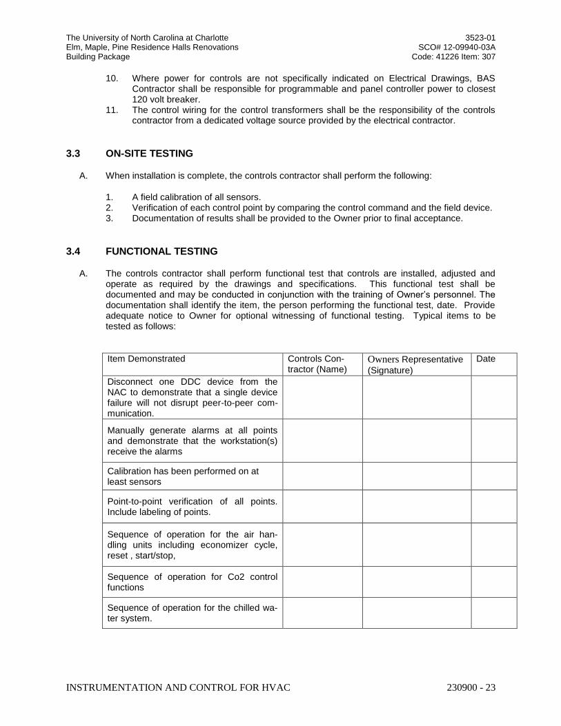
The University of North Carolina at Charlotte 3523-01 Elm, Maple, Pine Residence Halls Renovations SCO# 12-09940-03A Building Package Code: 41226 Item: 307
INSTRUMENTATION AND CONTROL FOR HVAC 230900 - 23
10. Where power for controls are not specifically indicated on Electrical Drawings, BAS Contractor shall be responsible for programmable and panel controller power to closest 120 volt breaker.
11. The control wiring for the control transformers shall be the responsibility of the controls contractor from a dedicated voltage source provided by the electrical contractor.
3.3 ON-SITE TESTING
A. When installation is complete, the controls contractor shall perform the following:
1. A field calibration of all sensors. 2. Verification of each control point by comparing the control command and the field device. 3. Documentation of results shall be provided to the Owner prior to final acceptance.
3.4 FUNCTIONAL TESTING
A. The controls contractor shall perform functional test that controls are installed, adjusted and operate as required by the drawings and specifications. This functional test shall be documented and may be conducted in conjunction with the training of Owner’s personnel. The documentation shall identify the item, the person performing the functional test, date. Provide adequate notice to Owner for optional witnessing of functional testing. Typical items to be tested as follows:
Item Demonstrated Controls Con-tractor (Name)
Owners Representative
(Signature)
Date
Disconnect one DDC device from the NAC to demonstrate that a single device failure will not disrupt peer-to-peer com-munication.
Manually generate alarms at all points and demonstrate that the workstation(s) receive the alarms
Calibration has been performed on at least sensors
Point-to-point verification of all points. Include labeling of points.
Sequence of operation for the air han-dling units including economizer cycle, reset , start/stop,
Sequence of operation for Co2 control functions
Sequence of operation for the chilled wa-ter system.
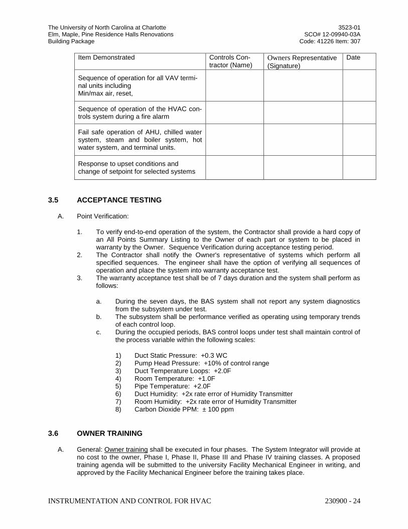
The University of North Carolina at Charlotte 3523-01 Elm, Maple, Pine Residence Halls Renovations SCO# 12-09940-03A Building Package Code: 41226 Item: 307
INSTRUMENTATION AND CONTROL FOR HVAC 230900 - 24
Item Demonstrated Controls Con-tractor (Name)
Owners Representative
(Signature)
Date
Sequence of operation for all VAV termi-nal units including Min/max air, reset,
Sequence of operation of the HVAC con-trols system during a fire alarm
Fail safe operation of AHU, chilled water system, steam and boiler system, hot water system, and terminal units.
Response to upset conditions and change of setpoint for selected systems
3.5 ACCEPTANCE TESTING
A. Point Verification:
1. To verify end-to-end operation of the system, the Contractor shall provide a hard copy of an All Points Summary Listing to the Owner of each part or system to be placed in warranty by the Owner. Sequence Verification during acceptance testing period.
2. The Contractor shall notify the Owner's representative of systems which perform all specified sequences. The engineer shall have the option of verifying all sequences of operation and place the system into warranty acceptance test.
3. The warranty acceptance test shall be of 7 days duration and the system shall perform as follows:
a. During the seven days, the BAS system shall not report any system diagnostics from the subsystem under test.
b. The subsystem shall be performance verified as operating using temporary trends of each control loop.
c. During the occupied periods, BAS control loops under test shall maintain control of the process variable within the following scales:
1) Duct Static Pressure: +0.3 WC 2) Pump Head Pressure: +10% of control range 3) Duct Temperature Loops: +2.0F 4) Room Temperature: +1.0F 5) Pipe Temperature: +2.0F 6) Duct Humidity: +2x rate error of Humidity Transmitter 7) Room Humidity: +2x rate error of Humidity Transmitter 8) Carbon Dioxide PPM: ± 100 ppm
3.6 OWNER TRAINING
A. General: Owner training shall be executed in four phases. The System Integrator will provide at no cost to the owner, Phase I, Phase II, Phase III and Phase IV training classes. A proposed training agenda will be submitted to the university Facility Mechanical Engineer in writing, and approved by the Facility Mechanical Engineer before the training takes place.
The University of North Carolina at Charlotte 3523-01 Elm, Maple, Pine Residence Halls Renovations SCO# 12-09940-03A Building Package Code: 41226 Item: 307
INSTRUMENTATION AND CONTROL FOR HVAC 230900 - 25
1. The first phase shall take place at the customer job site and will be scheduled at a time preceding owner acceptance. The purpose of the training is to provide an introduction and an overview of the FMS, and ensure POT is operational and functional with installed controllers.
2. The second phase of training shall be a follow-up training to address specific building system and questions of the operators. Training shall take place at the customer job site and will include a site-specific walk through and hands on site-specific instruction. Completion of this training shall be a condition of system acceptance.
3. Phase III and Phase IV training shall be provided as a follow-up and enrichment to the introductory and site-specific training.
3.7 PHASE I – ON SITE TRAINING
A. This training will give the operator with little or no experience with the FMS an introduction to:
1. Building automation fundamentals. 2. System architecture and functions as they pertain to the site. 3. System access using the Browser User Interface and FMS software. 4. Basic software controller programming and tuning. 5. Editing parameters such as set points and schedules. 6. Developing trends and day to day system monitoring. 7. The complete range of hardware and software products. 8. Building walk-thru.
3.8 PHASE II – ON SITE TRAINING
A. The manufacturer and the controls contractor shall provide 6 hours of on-site training in the maintenance and operation of the installed system for up to (4) personnel. The training shall be documented and a syllabus and O&M manuals shall be submitted and approved by Facilities Operations 2 weeks prior to the training. The training should include the following:
1. HVAC systems layout including the locations of air handlers, DDC controllers, VAV boxes, pumps. This will include a walk-thru at the building.
2. Review of O&M manual and control system as-builts:
a. Using As-Built documentation, Sequences of operation, control drawings, input/output summaries.
b. Field sensor and actuator location and maintenance. c. Field controller location and maintenance. d. FMS hardware operation and maintenance. e. FMS software site specific capabilities. f. Troubleshooting tools.
3. Sequence of operations for each control loop. 4. Demonstration and turnover to owner of POT.
a. Logon procedure. b. Use of laptop Lonworks tools or NAC plug-ins to configure ASCs or Program
FPCs. c. Password requirements.
5. Operation and troubleshooting including:
The University of North Carolina at Charlotte 3523-01 Elm, Maple, Pine Residence Halls Renovations SCO# 12-09940-03A Building Package Code: 41226 Item: 307
INSTRUMENTATION AND CONTROL FOR HVAC 230900 - 26
a. Modification of ASC or FPC setpoints, parameters, etc. b. Calibration and adjustment. c. Trending. d. Hands on training in the troubleshooting and replacement of components including
sensors, transmitters, control valves and actuators. Contractor shall have examples of each component and demonstrate measurement of input and output signals, and any operator adjustments available.
e. DDC controller functions and operation.
B. This phase of training shall be a minimum of 6 hours.
3.9 PHASE III – ON SITE TRAINING
A. No later than 6 months and no earlier than 4 months from building acceptance, the SI will repeat Phase I and Phase II training. Training to be consolidated into one 4 hour session.
3.10 PHASE IV – ON THE JOB TRAINING
A. SI and/or controls contractor shall coordinate all site visits and provide opportunity for university personnel to receive OJT during warranty work. Additionally, provide 2 days of OJT control loop tuning with owner utilizing owner POT.
B. The DDC contractor shall provide an additional 4hours on-site training session twelve (12) months after project completion. The purpose of the session will be to review any operational problems that have developed. In addition, the contractor will lead Facilities Operations personnel through a comprehensive annual preventative maintenance of the controls system. This shall be scheduled at least one (1) month in advance.
3.11 WARRANTY ACCESS
A. The Owner shall grant the Contractor, reasonable access to the BAS system during the warranty period. The owner shall provide at no cost to the contractor web browser access (VPN) for remote service and troubleshooting during warranty period.
END OF SECTION 230900
The University of North Carolina at Charlotte 3523-01 Elm, Maple, Pine Residence Halls Renovations SCO# 12-09940-03A Building Package Code: 41226 Item: 307
HYDRONIC PIPING 23 21 13-1
SECTION 23 21 13
HYDRONIC PIPING
PART 1 GENERAL
1.01 SECTION INCLUDES
A. Pipe and pipe fittings for: 1. Heating water piping system. 2. Chilled water piping system. 3. Condenser water piping system. 4. Equipment drains and overflows.
B. Valves: 1. Gate valves. 2. Globe or angle valves. 3. Ball valves. 4. Plug valves. 5. Butterfly valves. 6. Check valves.
1.02 RELATED SECTIONS
A. Section 08 31 00 - Access Doors and Panels.
B. Section 09 90 00 - Painting and Coating.
C. Section 23 05 16 - Expansion Fittings and Loops for HVAC Piping.
D. Section 23 05 48 - Vibration and Seismic Controls for HVAC Piping and Equipment.
E. Section 23 05 53 - Identification for HVAC Piping and Equipment.
F. Section 23 07 19 - HVAC Piping Insulation.
G. Section 22 05 16 - Expansion Fittings and Loops for Plumbing Piping.
H. Section 23 21 14 - Hydronic Specialties.
I. Section 23 25 00 - HVAC Water Treatment: Pipe cleaning.
J. Section 26 27 17 - Equipment Wiring: Electrical characteristics and wiring connections.
1.03 REFERENCES
A. ASME (BPV IX) - Boiler and Pressure Vessel Code, Section IX - Welding and Brazing Qualifications; The American Society of Mechanical Engineers.
B. ASME B16.3 - Malleable Iron Threaded Fittings; The American Society of Mechanical Engineers.
C. ASME B16.18 - Cast Copper Alloy Solder Joint Pressure Fittings; The American Society of Mechanical Engineers (ANSI B16.18).
D. ASME B16.22 - Wrought Copper and Copper Alloy Solder Joint Pressure Fittings; The American Society of Mechanical Engineers.
E. ASME B31.5 - Refrigeration Piping and Heat Transfer Components; The American Society of Mechanical Engineers.
F. ASME B31.9 - Building Services Piping; The American Society of Mechanical Engineers (ANSI/ASME B31.9).
The University of North Carolina at Charlotte 3523-01 Elm, Maple, Pine Residence Halls Renovations SCO# 12-09940-03A Building Package Code: 41226 Item: 307
HYDRONIC PIPING 23 21 13-2
G. ASTM A 53/A 53M - Standard Specification for Pipe, Steel, Black and Hot-Dipped, Zinc-Coated, Welded and Seamless.
H. ASTM A 234/A 234M - Standard Specification for Piping Fittings of Wrought Carbon Steel and Alloy Steel for Moderate and High Temperature Service.
I. ASTM B 32 - Standard Specification for Solder Metal.
J. ASTM B 88 - Standard Specification for Seamless Copper Water Tube.
K. ASTM B 88M - Standard Specification for Seamless Copper Water Tube (Metric).
L. ASTM D 1785 - Standard Specification for Poly(Vinyl Chloride) (PVC) Plastic Pipe, Schedules 40, 80, and 120.
M. ASTM D 2241 - Standard Specification for Poly (Vinyl Chloride) (PVC) Pressure-Rated Pipe (SDR Series).
N. ASTM D 2466 - Standard Specification for Poly(Vinyl Chloride) (PVC) Plastic Pipe Fittings, Schedule 40.
O. ASTM D 2467 - Standard Specification for Poly(Vinyl Chloride) (PVC) Plastic Pipe Fittings, Schedule 80.
P. ASTM D 2855 - Standard Practice for Making Solvent-Cemented Joints with Poly(Vinyl Chloride) (PVC) Pipe and Fittings.
Q. ASTM F 708 - Standard Practice for Design and Installation of Rigid Pipe Hangers.
R. ASTM F 2389-07 – Standard Specification for Pressure-rated Polypropylene (PP Piping Systems)
S. AWS A5.8/A5.8M - Specification for Filler Metals for Brazing and Braze Welding; American Welding Society.
T. AWS D1.1/D1.1M - Structural Welding Code - Steel; American Welding Society.
U. AWWA C105/A21.5 - Polyethylene Encasement for Ductile-Iron Pipe Systems; American Water Works Association (ANSI/AWWA C105/A21.5).
V. CSA B137.11 – Polypropylene (PP-R) Pipe and Fittings for Pressure Applications
W. MSS SP-58 - Pipe Hangers and Supports - Materials, Design and Manufacture; Manufacturers Standardization Society of the Valve and Fittings Industry, Inc..
X. MSS SP-69 - Pipe Hangers and Supports - Selection and Application; Manufacturers Standardization Society of the Valve and Fittings Industry, Inc..
Y. MSS SP-89 - Pipe Hangers and Supports - Fabrication and Installation Practices; Manufacturers Standardization Society of the Valve and Fittings Industry, Inc..
Z. NSF-ANSI 14 – Plastic Piping System Components and Related Materials.
1.04 SYSTEM DESCRIPTION
A. Where more than one piping system material is specified, ensure system components are compatible and joined to ensure the integrity of the system is not jeopardized. Provide necessary joining fittings. Ensure flanges, union, and couplings for servicing are consistently provided.
B. Use unions, flanges, and couplings downstream of valves and at equipment or apparatus connections. Do not use direct welded or threaded connections to valves, equipment or other apparatus.
The University of North Carolina at Charlotte 3523-01 Elm, Maple, Pine Residence Halls Renovations SCO# 12-09940-03A Building Package Code: 41226 Item: 307
HYDRONIC PIPING 23 21 13-3
C. Use dielectric nipples whenever jointing dissimilar metals.
D. Provide pipe hangers and supports in accordance with ASME B31.9 and MSS SP-69 unless indicated otherwise.
E. Use ball valves on piping 2" and below, and butterfly valves on piping over 2" for shut-off and to isolate equipment, part of systems, or vertical risers.
F. Use automatic flow control valves for flow limiting.
G. Use 3/4 inch ball valves with cap for drains at main shut-off valves, low points of piping, bases of vertical risers, and at equipment. Pipe to nearest floor drain.
1.05 SUBMITTALS
A. See Section 01 30 00 - Administrative Requirements, for submittal procedures.
B. Product Data: Include data on pipe materials, pipe fittings, valves, and accessories. Provide manufacturers catalogue information. Indicate valve data and ratings.
C. Welders Certificate: Include welders certification of compliance with ASME (BPV IX).
D. Manufacturer's Installation Instructions: Indicate hanging and support methods, joining procedures.
E. Project Record Documents: Record actual locations of valves and piping.
F. Maintenance Data: Include installation instructions, spare parts lists, exploded assembly views.
G. For underground hydronic piping. Signed and sealed by a professional engineer:
i. Show pipe sizes, locations, and elevations. Show piping in trench, conduit, and cased pipe with details showing clearances between piping and show insulation thickness. Show expansion compensation system.
1.06 QUALITY ASSURANCE
A. Manufacturer: Company specializing in manufacturing products of the type specified in this section, with minimum three years of documented experience.
B. Installer: Company specializing in performing work of the type specified in this section, with minimum five years of documented experience.
C. Welders: Certify in accordance with ASME (BPV IX).
D. Fusion Welding: Certify training per Manufacturer’s standards for each installer.
E. Polypropylene piping systems shall comply with ASTM F 2389.
F. Manufacturer of PP-R pipe must also manufacture same PP-R resin.
G. Special Engineered PP-R products shall be certified by NSF International as complying with NSF 14.
H. Provider of PP-R material shall have an Aquatherm certified master trainer on staff and have at least 8 years of experience in the US with this.
I. Supplier of PP-R material shall have at least 8 years of experience in the US with job names and reference of same ages or greater.
1.07 REGULATORY REQUIREMENTS
A. Conform to ASME B31.9 code for installation of piping system.
The University of North Carolina at Charlotte 3523-01 Elm, Maple, Pine Residence Halls Renovations SCO# 12-09940-03A Building Package Code: 41226 Item: 307
HYDRONIC PIPING 23 21 13-4
B. Welding Materials and Procedures: Conform to ASME (BPV IX) and applicable state labor regulations.
C. Provide certificate of compliance from authority having jurisdiction, indicating approval of welders.
1.08 DELIVERY, STORAGE, AND HANDLING
A. Accept valves on site in shipping containers with labeling in place. Inspect for damage.
B. Provide temporary protective coating on cast iron and steel valves.
C. Provide temporary end caps and closures on piping and fittings. Maintain in place until installation.
D. Protect piping systems from entry of foreign materials by temporary covers, completing sections of the work, and isolating parts of completed system.
1.09 ENVIRONMENTAL REQUIREMENTS
A. Do not install underground piping when bedding is wet or frozen.
1.10 EXTRA MATERIALS
A. See Section 01 60 00 - Product Requirements, for additional provisions.
B. Provide two repacking kits for each size and valve type.
1.11 WARRANTY
A. Manufacturer shall warrant pipe and fittings for 10 years to be free of defects in materials or manufacturing.
B. Warranty shall cover labor and materials costs of repairing and/or replacing defective materials and repairing any incidental damage caused by failure of the piping system due to defects in materials or manufacturing.
C. Warranty shall be in effect only upon submission by the contractor to the manufacturer valid pressure/leak test documentation indicating that the system was tested and passed the manufacturer’s pressure/leak test.
PART 2 PRODUCTS
2.01 HEATING WATER, AND CHILLED WATER PIPING, BURIED
A. CASED PIPING SYSTEM
1. Description: Factory insulated, cased piping system consisting of carrier pipe, insulation and jacket. Joints are field insulated. This system does not require the use of loose fill insulation in buried applications.
2. Manufacturers: a. Permapipe. b Thermacor c Rovanco. d Energy Task Force e Substitutions: See Section 01 60 00 - Product Requirements.
3 Steel Pipe: ASTM A 53 Grade B, Schedule 40, black. a. Fittings: ASTM A 234/A 234M, wrought steel welding type, factory prefabricated and pre-insulated. b. Joints: Welded in accordance with ANSI B 31.1 Code for Pressure Piping.

The University of North Carolina at Charlotte 3523-01 Elm, Maple, Pine Residence Halls Renovations SCO# 12-09940-03A Building Package Code: 41226 Item: 307
HYDRONIC PIPING 23 21 13-5
c. Casing: Polyurethane insulation with high density polyethylene jacket and heat shrink sleeves.
4. Insulation: Insulation shall be rigid 90 to 95% closed cell polyurethane with 1.9 to 2.1 pounds per cubic foot density and a coefficient of thermal conductivity (k) of .14 BTU (Hr.) (Sq. Ft.) (F/In) at 73 deg. f. Insulation thickness shall be 1 inch. Adjusted insulation thickness shall comply with the North Carolina Energy Conservation Code, section 503.2.8.
5. Jacketing Material shall be extruded black high density polyethylene (HDPE). The jacket throughout the entire system shall incorporate electric fusion, butt fusion or extrusion welding at all fittings, joint closures or other points of connection prohibiting the ingression of water.
6. Moisture Barrier End Seals shall be factory applied, sealed to the jacket and carrier pipe. End seals shall be certified as having passed a 20 foot head pressure test. End seals shall be high temperature mastic completely sealing the exposed end of the insulation. Field applied ends seals shall be installed at any field cut to the piping before continuing with the installation.
7. Piping shall meet H-20 Highway loading with 24” of backfill provided on top of pipe.
8. Anchor points and expansion compensation shall be designed by piping system manufacturer as needed.
B. POLYPROPYLENE (PP-R) PIPE AND FITTINGS 1. Description: Polypropylene piping system. This system describes bare piping. Loose fill
insulation described in section 230719, “Hydronic Piping Insulation” is required when Polypropylene piping is used in buried applications.
2. Pipe shall be manufactured from a PP-R resin (Fusiolen) meeting the short-term properties and
long-term strength requirements of ASTM F 2389. The pipe shall contain no rework or recycled materials except that generated in the manufacturer's own plant from resin of the same specification from the same raw material. All pipe shall be made in an extrusion process. Hydronic hot water applications shall contain a fiber layer (faser) to restrict thermal expansion. All pipe shall comply with the rated pressure requirements of ASTM F 2389.
3.Pipe shall be Aquatherm® Green Pipe®, or Green Pipe® MF (Faser®), SDR 7.4, available from
Aquatherm, NA. Piping specifications and ordering information are available at
www.aquatherm.com. 4. Fittings shall be manufactured from a PP-R resin (Fusiolen) meeting the short-term properties
and long-term strength requirements of ASTM F 2389. The fittings shall contain no rework or recycled materials except that generated in the manufacturer's own plant from resin of the same specification from the same raw material. All fittings shall be certified as complying with ASTM F 2389.
5. Polypropylene Fittings: socket fusion, butt fusion, electrofusion, or fusion outlet fittings shall be used for fusion weld joints between pipe and fittings.
6. Mechanical fittings and transition fittings shall be used where transitions are made to other piping materials or to valves and appurtenances.
7. Polypropylene pipe shall not be threaded. Threaded transition fittings per ASTM F 2389 shall be used where a threaded connection is required.
8. Polypropylene pipe used for hot water distribution shall include a fiberglass-reinforced layer to
reduce thermal expansion/contraction.
The University of North Carolina at Charlotte 3523-01 Elm, Maple, Pine Residence Halls Renovations SCO# 12-09940-03A Building Package Code: 41226 Item: 307
HYDRONIC PIPING 23 21 13-6
9. Plastic, Pipe-Flange Gasket, Bolts, and Nuts: Type and material recommended by piping system manufacturer unless otherwise indicated.
10. Plastic-to-Metal Transition Fittings shall be PP-R one-piece fitting with threaded stainless steel,
brass, or copper insert and one PP-R fusion weld joint end.
C. UNDERGROUND TRACER WIRE AND WARNING TAPE 1. All underground piping and utilities (both metallic and non-metallic), except copper pipe, shall
have a separate copper tracer wire and non-metallic warning tape installed above the utility line. 2. The tracer wire shall be traced for continuity prior to backfill, immediately upon completion of
backfill and compaction and once again during final utility location/as-built at the end of the project. This also will include landscape irrigation mains to the points of the valves. All above ground utility features such as vaults, manholes, valves, handholds, etc to be properly labeled. Contractor shall provide an inventory of all installed outdoor utility features including type and model.
3. Identification Tape: The 1st stage of identification shall be a buried warning tape. This tape shall provide an early warning at shallow depth excavation. The tape shall be 6" wide, and buried approximately 18" to 30" above the service pipe, but a minimum of 10" below finished grade. It shall consist of multiple layers of polyethylene with an overall thickness of 3 to 5 mils. It shall be installed continuous from valve box to valve box or manhole to manhole, and shall terminate just outside of valve box or manhole wall. The black colored lettering on the warning tape shall be abrasion resistant and be imprinted on a color-coded background that conforms to APWA color code standards. The lettering on the tape should name the utility it is protecting. (i.e. Caution Buried Sewer Line Below).
4. Tracer Wire: The 2nd stage of identification shall be a buried tracer wire. This tracer wire shall provide pipeline identification, be fully detectable from above grade utility locators, and be able to provide a depth reference point to top of pipe.
5. All pipe, including lawn irrigation lines, and metallic pipe with compression gasket fittings installed underground shall have a tracer wire installed along the length of the pipe. The wire shall be taped to the bottom of the pipe at a maximum of 10' intervals and not allowed to "float freely" within the backfill.
6. Tracer wire shall be single-conductor, 12 gauge minimum, copper single-conductor wire with type "UF" (Underground Feeder) insulation, and shall be continuous along the pipeline passing through the inside of each valve box. A #12 AWG or heavier (smaller AWG number), solid, insulated (RHW, THW, or polyethylene insulation is recommended), copper wire shall be taped to pipe at 10 foot intervals. Do not wrap wire around pipe. The wire must be one continuous, unbroken length. Coil tracer wire at meter location and street end with enough wire to extend a minimum of two feet above grade.
a. Tracer wire boxes: Plastic gas and water services longer than 1000 feet in
length from curb valve to meter riser must have tracer wire boxes installed in accordance with UNC Charlotte standards. Provide terminal box at each building piping entrance and at Oak Hall central energy plant and at intervals no less than 1000 lineal feet of piping.
2.02 HEATING WATER AND CHILLED WATER PIPING, ABOVE GRADE
A. Steel Pipe: ASTM A 53/A 53M, Schedule 40, black. Fittings: ASTM B 16.3, malleable iron or ASTM A 234/A 234M, wrought steel welding type fittings.Joints: Threaded for pipe 2 inch and under, or AWS D1.1 welded for pipe over 2 inches.
The University of North Carolina at Charlotte 3523-01 Elm, Maple, Pine Residence Halls Renovations SCO# 12-09940-03A Building Package Code: 41226 Item: 307
HYDRONIC PIPING 23 21 13-7
B. Copper Tube: ASTM B 88 (ASTM B 88M), Type L (B), hard drawn, 4 inches and smaller. Fittings: ASME B16.18, cast brass, or ASME B16.22, wrought copper and bronze. Joints: 1" and Smaller: ASTM B 32, alloy Sn95 solder, 1-1/4" and Larger: AWS A5-8, BCuP silver braze.
C. Polypropylene Pipe 1. Pipe shall be manufactured from a PP-R resin meeting the short-term properties and
long-term strength requirements of ASTM F 2389. The pipe shall contain no rework or recycled materials except that generated in the manufacturer's own plant from resin of the same specification from the same raw material. All pipe shall be made in an extrusion process. Hydronic hot water piping shall contain a fiber layer (faser) to restrict thermal expansion. All pipe shall comply with the rated pressure requirements of ASTM F 2389 or CSA B137.11. All pipe shall be comply ASTM F 2389.
2. Chilled water pipe shall be Aquatherm® Green Pipe® SDR 7.4 MF® or Blue Pipe® SDR
11 MF®, or approved equal available from Aquatherm, NA. Piping specifications and ordering information are available at www.aquatherm.com.
3. Hot water pipe shall be Aquatherm® Green Pipe® SD 7.4 or approved equal from
Aguatherm, NA. Piping specifications and ordering information are available at www.aquatherm.com.
4. Fittings shall be manufactured from a PP-R resin meeting the short-term properties and long-term strength requirements of ASTM F 2389. The fittings shall contain no rework or recycled materials except that generated in the manufacturer's own plant from resin of the same specification from the same raw material. All fittings shall be certified as complying ASTM F 2389.
5. Fittings shall be Aquatherm® Green Pipe® or Blue Pipe® available from Aquatherm, NA. Fittings specifications and ordering information are available at www.aquatherm.com.
2.03 EQUIPMENT DRAINS AND OVERFLOWS
A. Steel Pipe: ASTM A 53/A 53M, Schedule 40 galvanized. 1. Fittings: Galvanized cast iron, or ASME B16.3 malleable iron. 2. Joints: Threaded, or grooved mechanical couplings.
B. Copper Tube: ASTM B 88 (ASTM B 88M), Type L (B), drawn. 1. Fittings: ASME B16.18, cast brass, or ASME B16.22 solder wrought copper. 2. Joints: Solder, lead free, ASTM B 32, HB alloy (95-5 tin-antimony).
2.04 PIPE HANGERS AND SUPPORTS
A. Conform to ASME B31.9, ASTM F 708, MSS SP-58, MSS SP-69, and MSS SP-89.
B. Hangers for Pipe Sizes 1/2 to 1-1/2 Inch: Malleable iron, adjustable swivel, split ring.
C. Hangers for Cold Pipe Sizes 2 Inches and Over: Carbon steel, adjustable, clevis.
D. Hangers for Hot Pipe Sizes 2 to 4 Inches: Carbon steel, adjustable, clevis.
E. Hangers for Hot Pipe Sizes 6 Inches and Over: Adjustable steel yoke, cast iron roll, double hanger.
F. Multiple or Trapeze Hangers: Steel channels with welded spacers and hanger rods.
G. Multiple or Trapeze Hangers for Hot Pipe Sizes 6 Inches and Over: Steel channels with welded spacers and hanger rods, cast iron roll.
The University of North Carolina at Charlotte 3523-01 Elm, Maple, Pine Residence Halls Renovations SCO# 12-09940-03A Building Package Code: 41226 Item: 307
HYDRONIC PIPING 23 21 13-8
H. Wall Support for Pipe: Welded steel bracket and wrought steel clamp.
I. Wall Support for Hot Pipe Sizes 6 Inches and Over: Welded steel bracket and wrought steel clamp with adjustable steel yoke and cast iron roll.
J. Vertical Support: Steel riser clamp.
K. Floor Support for Cold Pipe: Cast iron adjustable pipe saddle, lock nut, nipple, floor flange, and concrete pier or steel support.
L. Floor Support for Hot Pipe Sizes to 4 Inches: Cast iron adjustable pipe saddle, lock nut, nipple, floor flange, and concrete pier or steel support.
M. Floor Support for Hot Pipe Sizes 6 Inches and Over: Adjustable cast iron roll and stand, steel screws, and concrete pier or steel support.
N. Copper Pipe Support: Carbon steel ring, adjustable, copper plated.
O. Hanger Rods: Mild steel threaded both ends, threaded one end, or continuous threaded.
P. Inserts: Malleable iron case of galvanized steel shell and expander plug for threaded connection with lateral adjustment, top slot for reinforcing rods, lugs for attaching to forms; size inserts to suit threaded hanger rods.
2.05 UNIONS, FLANGES, AND COUPLINGS (metal pipe)
A. Unions for Pipe 2 Inches and Under: 1. Ferrous Piping: 150 psig malleable iron, threaded. 2. Copper Pipe: Bronze, soldered joints.
B. Flanges for Pipe Over 2 Inches: 1. Ferrous Piping: 150 psig forged steel, slip-on. 2. Copper Piping: Bronze. 3. Gaskets: 1/16 inch thick preformed neoprene.
C. Dielectric Connections: Nipple with galvanized or plated steel threaded end, copper solder end, water impervious isolation barrier.
2.06 GATE VALVES (metal pipe)
A. Manufacturers: 1. Conbraco Industries: www.conbraco.com. 2. Nibco, Inc: www.nibco.com. 3. Milwaukee Valve Company: www.milwaukeevalve.com. 4. Substitutions: See Section 01 60 00 - Product Requirements.
B. Up To and Including 2 Inches: 1. Bronze body, bronze trim, screwed bonnet, rising stem, handwheel, inside screw with
backseating stem, solid wedge disc, alloy seat rings, solder ends.
C. Over 2 Inches: 1. Iron body, bronze trim, bolted bonnet, rising stem, handwheel, outside screw and yoke,
solid wedge disc with bronze seat rings, flanged ends.
2.07 GLOBE OR ANGLE VALVES (metal pipe)
A. Manufacturers: 1. Conbraco Industries: www.conbraco.com. 2. Nibco, Inc: www.nibco.com. 3. Milwaukee Valve Company: www.milwaukeevalve.com. 4. Substitutions: See Section 01 60 00 - Product Requirements.
The University of North Carolina at Charlotte 3523-01 Elm, Maple, Pine Residence Halls Renovations SCO# 12-09940-03A Building Package Code: 41226 Item: 307
HYDRONIC PIPING 23 21 13-9
B. Up To and Including 2 Inches: 1. Bronze body, bronze trim, screwed bonnet, rising stem and handwheel, inside screw
with backseating stem, renewable composition disc and bronze seat, solder or threaded ends.
C. Over 2 Inches: 1. Iron body, bronze trim, bolted bonnet, rising stem, handwheel, outside screw and yoke,
rotating plug-type disc with renewable seat ring and disc, flanged ends.
2.08 BALL VALVES (metal pipe)
A. Manufacturers: 1. Conbraco Industries: www.conbraco.com. 2. Nibco, Inc: www.nibco.com. 3. Milwaukee Valve Company: www.milwaukeevalve.com. 4. Substitutions: See Section 01 60 00 - Product Requirements.
B. Up To and Including 2 Inches: 1. Bronze body, chrome plated brass or stainless steel ball, teflon seats and stuffing box
ring, lever handle with balancing stops.
C. Over 2 Inches: 1. Cast steel body, chrome plated steel ball, teflon seat and stuffing box seals, lever
handle, flanged.
2.09 PLUG VALVES (metal pipe)
A. Manufacturers: 1. Conbraco Industries: www.conbraco.com. 2. Nibco, Inc: www.nibco.com. 3. Milwaukee Valve Company: www.milwaukeevalve.com. 4. Substitutions: See Section 01 60 00 - Product Requirements.
B. Up To and Including 2 Inches: 1. Bronze body, bronze tapered plug, non-lubricated, teflon packing, threaded ends. 2. Operator: One plug valve wrench for every ten plug valves minimum of one.
C. Over 2 Inches: 1. Cast iron body and plug, pressure lubricated, teflon packing, flanged ends. 2. Operator: Each plug valve with a wrench with set screw.
2.10 BUTTERFLY VALVES (metal pipe)
A. Manufacturers: 1. Hammond Valve: www.hammondvalve.com. 2. Crane Valve: www.cranevalve.com. 3. Milwaukee Valve Company: www.milwaukeevalve.com. 4. Substitutions: See Section 01 60 00 - Product Requirements.
B. Body: Cast or ductile iron with resilient replaceable EPDM seat, wafer or lug ends, extended neck.
C. Disc: Aluminum bronze.
D. Operator: 10 position lever handle or infinite position lever handle with memory stop.
2.11 SWING CHECK VALVES (metal pipe)
A. Manufacturers: 1. Hammond Valve: www.hammondvalve.com. 2. Nibco, Inc: www.nibco.com.
The University of North Carolina at Charlotte 3523-01 Elm, Maple, Pine Residence Halls Renovations SCO# 12-09940-03A Building Package Code: 41226 Item: 307
HYDRONIC PIPING 23 21 13-10
3. Milwaukee Valve Company: www.milwaukeevalve.com. 4. Substitutions: See Section 01 60 00 - Product Requirements.
B. Up To and Including 2 Inches: 1. Bronze body, bronze trim, bronze rotating swing disc, with composition disc, solder or
threaded ends.
C. Over 2 Inches: 1. Iron body, bronze trim, bronze or bronze faced rotating swing disc, renewable disc and
seat, flanged ends.
2.12 SPRING LOADED CHECK VALVES (metal pipe)
A. Manufacturers: 1. Hammond Valve: www.hammondvalve.com. 2. Crane Valve: www.cranevalve.com. 3. Milwaukee Valve Company: www.milwaukeevalve.com. 4. Substitutions: See Section 01 60 00 - Product Requirements.
B. Iron body, bronze trim, split plate, hinged with stainless steel spring, resilient seal bonded to body, wafer or threaded lug ends.
2.13 VALVES (polypropylene pipe)
A. Valves shall be manufactured in accordance with the manufacturer’s specifications and shall
comply with the performance requirements of ASTM F 2389 or CSA B137.11. The valves shall contain no rework or recycled thermoplastic materials except that generated in the manufacturer's own plant from resin of the same specification from the same raw material.
B. Valves shall be Aquatherm® available from Aquatherm, NA. Valve specifications and ordering
information are available at
PART 3 EXECUTION
3.01 PREPARATION
A. Ream pipe and tube ends. Remove burrs. Bevel plain end ferrous pipe.
B. Remove scale and dirt on inside and outside before assembly.
C. Prepare piping connections to equipment with flanges or unions.
D. Keep open ends of pipe free from scale and dirt. Protect open ends with temporary plugs or caps.
E. After completion, fill, clean, and treat systems. Refer to Section 23 25 00 for additional requirements.
F. Do not back fill piping trench until field quality control testing has been completed and results approved.
3.02 INSTALLATION
A. Install in accordance with manufacturer's instructions.
B. Install heating water, glycol, chilled water, condenser water, and engine exhaust piping to ASME B31.9 requirements.
C. Route piping in orderly manner, parallel to building structure, and maintain gradient.
D. Install piping to conserve building space and to avoid interfere with use of space.
The University of North Carolina at Charlotte 3523-01 Elm, Maple, Pine Residence Halls Renovations SCO# 12-09940-03A Building Package Code: 41226 Item: 307
HYDRONIC PIPING 23 21 13-11
E. Group piping whenever practical at common elevations.
F. Sleeve pipe passing through partitions, walls and floors.
G. Slope piping and arrange to drain at low points. Provide drain valves at all low points and air vents at all high points.
H. Install piping to allow for expansion and contraction without stressing pipe, joints, or connected equipment. Refer to Section 22 05 16.
I. Inserts: 1. Provide inserts for placement in concrete formwork. 2. Provide inserts for suspending hangers from reinforced concrete slabs and sides of
reinforced concrete beams. 3. Provide hooked rod to concrete reinforcement section for inserts carrying pipe over 4
inches. 4. Where concrete slabs form finished ceiling, locate inserts flush with slab surface. 5. Where inserts are omitted, drill through concrete slab from below and provide through-
bolt with recessed square steel plate and nut recessed into and grouted flush with slab.
J. Pipe Hangers and Supports: 1. Install in accordance with ASME B31.9, ASTM F 78 and MSS SP-89. 2. Support horizontal piping as scheduled. Provide minimum of one hanger per pipe
section. 3. Install hangers to provide minimum 1/2 inch space between finished covering and
adjacent work. 4. Place hangers within 12 inches of each horizontal elbow, tee or cross-fitting. 5. Use hangers with 1-1/2 inch minimum vertical adjustment. Design hangers for pipe
movement without disengagement of supported pipe. 6. Support vertical piping at every floor. Support riser piping independently of connected
horizontal piping. 7. Where several pipes can be installed in parallel and at same elevation, provide multiple
or trapeze hangers. 8. Provide copper plated hangers and supports for copper piping. 9. Prime coat exposed steel hangers and supports. Refer to Section 09 90 00. Hangers
and supports located in crawl spaces, pipe shafts, and suspended ceiling spaces are not considered exposed.
K. Provide clearance in hangers and from structure and other equipment for installation of insulation and access to valves and fittings. Refer to Section 22 07 19.
L. Provide access where valves and fittings are not exposed. Coordinate size and location of access doors with Section 08 31 00.
M. Use eccentric reducers to maintain top of pipe level.
N. Where pipe support members are welded to structural building framing, scrape, brush clean, and apply one coat of zinc rich primer to welds.
O. Prepare and paint unfinished pipe, fittings, supports, and accessories. Refer to Section 09 90 00.
P. Install valves with stems upright or horizontal, not inverted.
Q. Where polypropylene piping is installed above grade and a Plenum-rated Piping System is
needed, then the pipe shall be wrapped and/or insulated with standard pipe insulation, field installed. The pipe wrap or insulation shall meet the requirements of CAN/ULC-S102.2-03 or
The University of North Carolina at Charlotte 3523-01 Elm, Maple, Pine Residence Halls Renovations SCO# 12-09940-03A Building Package Code: 41226 Item: 307
HYDRONIC PIPING 23 21 13-12
ASTM E84. The system shall have a Flame Spread Classification of less than 25 and Smoke Development rating of less than 50.
R. Where the PP-R pipe will be exposed to direct UV light for more than 30 days, it shall be
provided with a Factory applied, UV-resistant coating or alternative UV protection. 3.03 FUSION WELDING OF JOINTS (PP-R Pipe)
A. Install fittings and joints using socket-fusion, elecrofusion, or butt-fusion as applicable for the fitting or joint type. All fusion-weld joints shall be made in accordance with the pipe and fitting manufacturer’s specifications and product standards.
B. Fusion-weld tooling, welding machines, and electrofusion devices shall be as specified by the pipe and fittings manufacturer.
C. Prior to joining, the pipe and fittings shall be prepared in accordance with ASTM F 2389 and the manufacturer’s specifications.
D. Joint preparation, setting and alignment, fusion process, cooling times and working pressure shall be in accordance with the pipe and fitting manufacturer’s specifications.
3.04 VALVE APPLICATIONS (PP-R Pipe)
A. Install gate valves close to the main on each branch and riser serving 2 or more equipment connections and where indicated.
B. Install gate or ball valves on the inlet to each equipment item and elsewhere as indicated.
C. Install drain valve at the base of each riser, at low points of horizontal runs, and where required to drain hydronic piping system.
3.05 SCHEDULES
A. Hanger Spacing for Copper Tubing. 1. 1/2 inch and 3/4 inch: Maximum span, 5 feet; minimum rod size, 1/4 inch. 2. 1 inch: Maximum span, 6 feet; minimum rod size, 1/4 inch. 3. 1-1/2 inch and 2 inch: Maximum span, 8 feet; minimum rod size, 3/8 inch. 4. 2-1/2 inch: Maximum span, 9 feet; minimum rod size, 3/8 inch. 5. 3 inch: Maximum span, 10 feet; minimum rod size, 3/8 inch. 6. 4 inch: Maximum span, 12 feet; minimum rod size, 1/2 inch. 7. 6 inch: Maximum span, 14 feet; minimum rod size, 1/2 inch. 8. 8 inch: Maximum span, 16 feet; minimum rod size, 5/8 inch. 9. 10 inch: Maximum span, 18 feet; minimum rod size, 3/4 inch. 10. 12 inch: Maximum span, 19 feet; minimum rod size, 7/8 inch.
B. Hanger Spacing for Steel Piping. 1. 1/2 inch, 3/4 inch, and 1 inch: Maximum span, 7 feet; minimum rod size, 1/4 inch. 2. 1-1/4 inches: Maximum span, 8 feet; minimum rod size, 3/8 inch. 3. 1-1/2 inches: Maximum span, 9 feet; minimum rod size, 3/8 inch. 4. 2 inches: Maximum span, 10 feet; minimum rod size, 3/8 inch. 5. 2-1/2 inches: Maximum span, 10 feet; minimum rod size, 3/8 inch. 6. 3 inches: Maximum span, 10 feet; minimum rod size, 3/8 inch.
The University of North Carolina at Charlotte 3523-01 Elm, Maple, Pine Residence Halls Renovations SCO# 12-09940-03A Building Package Code: 41226 Item: 307
HYDRONIC PIPING 23 21 13-13
7. 4 inches: Maximum span, 14 feet; minimum rod size, 1/2 inch. 8. 6 inches: Maximum span, 17 feet; minimum rod size, 1/2 inch. 9. 8 inches: Maximum span, 19 feet; minimum rod size, 5/8 inch. 10. 10 inches: Maximum span, 20 feet; minimum rod size, 3/4 inch. 11. 12 inches: Maximum span, 20 feet; minimum rod size, 7/8 inch. 12. 14 inches: Maximum span, 20 feet; minimum rod size, 1 inch. 13. 16 inches: Maximum span, 20 feet; minimum rod size, 1 inch. 14. 18 inches: Maximum span, 20 feet; minimum rod size, 1-1/4 inch. 15. 20 inches: Maximum span, 20 feet; minimum rod size, 1-1/4 inch.
C. Hanger Spacing for Plastic Piping. 1. 1/2 inch: Maximum span, 42 inches; minimum rod size, 1/4 inch. 2. 3/4 inch: Maximum span, 45 inches; minimum rod size, 1/4 inch. 3. 1 inch: Maximum span, 51 inches; minimum rod size, 1/4 inch. 4. 1-1/4 inches: Maximum span, 57 inches; minimum rod size, 3/8 inch. 5. 1-1/2 inches: Maximum span, 63 inches; minimum rod size, 3/8 inch. 6. 2 inches: Maximum span, 69 inches; minimum rod size, 3/8 inch. 7. 3 inches: Maximum span, 7 feet; minimum rod size, 3/8 inch. 8. 4 inches: Maximum span, 8 feet; minimum rod size, 1/2 inch. 9. 6 inches: Maximum span, 10 feet; minimum rod size, 1/2 inch. 10. 8 inches: Maximum span, 10 feet; minimum rod size, 5/8 inch. 11. 10 inches: Maximum span, 10 feet; minimum rod size, 3/4 inch. 12. 12 inches: Maximum span, 10 feet; minimum rod size, 7/8 inch. 13. 14 inches: Maximum span, 10 feet; minimum rod size, 1 inch. 14. 16 inches: Maximum span, 10 feet; minimum rod size, 1 inch. 15. 18 inches: Maximum span, 10 feet; minimum rod size, 1-1/4 inch.
D. Reduce hanger spacing as required to meet the deflection requirements of ASME B31.9. For example, a 4-foot run of 1" copper tubing that includes a 1-foot drop and a 1-foot rise (to pass under an obstruction) would have 6 linear feet of pipe. In this case, hanger spacing would be reduced from 6 feet (scheduled) to 4 feet.
3.06 TESTING
A. Metal Pipe
1. All piping shall be tested with water at 150% of operating pressure and not less than 100 psi pressure. During test, the piping shall be isolated from equipment and ends capped. Pressure shall be provided by means of a test pump and maintained for at least 24 hours. Pressure shall not drop more than 5 psi during 24-hour test period with pump isolated from system. In making piping test, the Contractor shall isolate and safeguard equipment and specialties in piping to protect them against injury from test pressure.
2. Final test shall consist of subjecting the piping and equipment to water tests, duplicating as far as possible the normal operating conditions under which the piping systems shall function. During the application of the final test, proper provisions shall be made to remove all air and to expose all joints to the service under which they will operate. Under the final test all joints shall be made absolutely tight, the piping shall expand or contract freely on the supports, and shall maintain good alignment throughout.
3. The Owner reserves the right to utilize any testing procedure listed in Chapter VI ANSI/ASME B31.1 to verify structural integrity of any weld(s) not meeting Engineer's approval. If integrity of weld(s) is found to be in compliance with ANSI B31.1, Owner will pay for additional testing. If weld(s) is found to be deficient, Contractor shall be responsible for all costs associated with the testing and repair of the weld(s).
B. PP-R Pipe
The University of North Carolina at Charlotte 3523-01 Elm, Maple, Pine Residence Halls Renovations SCO# 12-09940-03A Building Package Code: 41226 Item: 307
HYDRONIC PIPING 23 21 13-14
1. While still accessible all piping shall be pressure/leak tested to the manufacturer’s standards. Tests shall be carried out using water, compressed air or a mixture of the two. The test pressure shall be 1.5 times the operating pressure or 150 psi, whichever is greater. Any leaks detected shall be repaired at the contractor’s expense by removing the leaking part and replacing with new parts welded per the pipe manufacturer’s guidelines. See www.aquatherm.com for additional details and forms.
END OF SECTION
The University of North Carolina at Charlotte 3523-01 Elm, Maple, Pine Residence Halls Renovations SCO# 12-09940-03A Building Package Code: 41226 Item: 307
TERMINAL HEAT TRANSFER UNITS 23 81 01-1
SECTION 23 81 01
TERMINAL HEAT TRANSFER UNITS
PART 1 GENERAL
1.01 SECTION INCLUDES
A. Unit heaters.
B. Cabinet unit heaters.
C. Fan-coil units.
1.02 RELATED SECTIONS
A. Section 23 05 13 - Common Motor Requirements for HVAC Equipment.
B. Section 23 21 13 - Hydronic Piping.
C. Section 23 21 14 - Hydronic Specialties.
D. Section 23 09 13 - Instrumentation and Control Devices for HVAC.
E. Section 23 82 16 – Air Coils
F. Section 26 27 17 - Equipment Wiring: Electrical characteristics and wiring connections. Electrical supply to units.
1.03 SUBMITTALS
A. See Section 01 30 00 - Administrative Requirements, for submittal procedures.
B. Shop Drawings: 1. Indicate cross sections of cabinets, grilles, bracing and reinforcing, and typical
elevations. 2. Submit schedules of equipment including coil and fan performance. 3. Indicate mechanical and electrical service locations and requirements.
C. Manufacturer's Instructions: Provide installation instructions and recommendations.
D. Operation and Maintenance Data: Provide manufacturer's operating instructions, maintenance manuals and repair data, and parts listings.
E. Warranty: Submit manufacturer's warranty and ensure forms have been completed in Owner's name and registered with manufacturer.
1.04 QUALITY ASSURANCE
A. Products Requiring Electrical Connection: Listed and classified by Underwriters' Laboratories, Inc., or a third party agency accredited by NCBCC (North Carolina Building Code Council) to Label Electrical and Mechanical Equipment, as suitable for the purpose specified and indicated.
1.05 DELIVERY, STORAGE AND HANDLING
A. Deliver, store, and protect products under provisions of Section 01 60 00.
B. Protect units from physical damage by storing in protected areas and leaving factory covers in place.
The University of North Carolina at Charlotte 3523-01 Elm, Maple, Pine Residence Halls Renovations SCO# 12-09940-03A Building Package Code: 41226 Item: 307
TERMINAL HEAT TRANSFER UNITS 23 81 01-2
1.06 WARRANTY
A. See Section 01 78 00 - Closeout Submittals, for additional warranty requirements.
B. Provide manufacturer's standard warranty.
1.07 EXTRA MATERIALS
A. See Section 01 60 00 - Product Requirements, for additional provisions.
B. Supply one spare set of filters for each unit.
1.08 INTEGRATION
A. Equipment shall interface with the NAC (Network Area Controller) through Mod bus RTU, BACNET MS/TP or Lonworks.
PART 2 PRODUCTS
2.01 UNIT HEATERS
A. Manufacturers: 1. Slant/Fin Corporation: www.slantfin.com. 2. Sterling Hydronics/Mestek Technology, Inc: www.sterlingheat.com. 3. The Trane Company: www.trane.com. 4. Modine: www.modine.com. 5. Beacon-Morris: www.beacon-morris.com. 6. Dunham-Bush: www.dunham-bush.com. 7. Reznor: www.rezspec.com. 8. Markel: www.markel-products.com 8.9. Indeeco: www.indeeco.com 9.10. Substitutions: See Section 01 60 00 - Product Requirements.
B. Coils: Corrosion resistant steel sheathed type elements mechanically bonded to common corrosion resistant steel fins. Each element shall consist of helically coiled nickel chromium alloy resistant wire surrounded by magnesium oxide.
C. Casing: 0.0478 inch steel with threaded pipe connections for hanger rods.
D. Finish: Factory applied baked.
E. Fan: Direct drive propeller type, statically and dynamically balanced, with fan guard; horizontal models with permanently lubricated sleeve bearings; vertical models with grease lubricated ball bearings.
F. Air Outlet: Adjustable pattern diffuser on projection models and double deflection louvers on horizontal throw models.
G. Motor: Permanently lubricated sleeve bearings on horizontal models, grease lubricated ball bearings on vertical models. Refer to Section 22 05 13.
H. Control: Local disconnect switch. Thermostat as indicated on drawings.
I. Capacity: As scheduled.
2.02 CABINET UNIT HEATERS
A. Manufacturers: 1. Slant/Fin Corporation: www.slantfin.com. 2. Sterling Hydronics/Mestek Technology, Inc: www.sterlingheat.com. 3. The Trane Company: www.trane.com. 4. Substitutions: See Section 01 60 00 - Product Requirements.
The University of North Carolina at Charlotte 3523-01 Elm, Maple, Pine Residence Halls Renovations SCO# 12-09940-03A Building Package Code: 41226 Item: 307
TERMINAL HEAT TRANSFER UNITS 23 81 01-3
B. Coils: Evenly spaced aluminum fins mechanically bonded to copper tubes, designed for 100 psi and 220 degrees F. Provide an air vent and drain plug in coils.
C. Cabinet: 0.0598 inch steel with exposed corners and edges rounded, easily removed panels, glass fiber insulation and integral air outlet and inlet grilles where scheduled.
D. Finish: Factory applied baked.
E. Fans: Centrifugal forward-curved double-width wheels, statically and dynamically balanced, direct driven.
F. Motor: Tap wound multiple speed permanent split capacitor or shaded pole with sleeve bearings, resiliently mounted.
G. Control: Multiple speed switch, factory wired, located in cabinet.
H. Filter: Easily removed 1 inch thick throw-away type, located to filter air before coil.
I. Capacity: As scheduled.
2.03 FAN-COIL UNITS
A. Manufacturers: 1. Daikin: www.daikincomfort.com. 2. Johnson Controls: www.johnsoncontrols.com. 3. Trane: www.trane.com. 4. Substitutions: See Section 01 60 00 - Product Requirements.
B. Unit Configuration:
1. Unit shall be four-pipe system blow-through configuration with completely removable chassis. Filter, fan assembly, drain line and motor shall be accessible by removing the return air grille panel. Internal controls, service valves, drain pan and coil shall be accessible by removing the access and sound baffle panel. Hand of unit shall be tabulated in the schedule
C. Cabinet:
1. Cabinet shall be fabricated of heavy-gauge galvanized steel and fully insulated with 1/2" multi-density glass fiber. An insulated galvanized steel access and sound baffle panel shall completely enclose the coil section.
2. Plaster Frame and Return Grille – The return air grille panel shall be heavy-gauge steel with a stamped (bar type) grille and semi-gloss finish and extend 5/8" in front of unit face. A plaster frame shall be provided to hold the return air grille panel away from the wall when the unit is furred in. A snap-on return air grille panel shall be provided with the plaster frame.
D. Coils:
1. Units shall be AHRI certified standard low flow cooling coil plus one-row heating coil in four-pipe systems. All coils shall be seamless copper tubes in a staggered pattern with rippled and corrugated aluminum fins. Tubes shall be mechanically expanded into the fin collars for positive fin-to tube bond. Coils shall have manual air vents. Internal piping shall allow for vertical riser expansion of ±1". Coil performance shall be as tabulated in the schedule. Coil shall be positioned to provide positive condensate drainage.
E. Fan Assembly:
1. Fan housings shall be painted steel with integral scroll and separate inlets. Fan wheels shall be painted steel DWDI forward curved centrifugal direct type.
The University of North Carolina at Charlotte 3523-01 Elm, Maple, Pine Residence Halls Renovations SCO# 12-09940-03A Building Package Code: 41226 Item: 307
TERMINAL HEAT TRANSFER UNITS 23 81 01-4
2. Motors shall be permanent split capacitor type 115/60/1 with sleeve bearings, oilers, inherent thermal overload protection with automatic reset and resilient mounts.
F. Filters:
1. Filters shall be nominal 1" thick throwaway.
G. Drain Pan:
1. Drain pan shall be galvanized (stainless) steel with drain line and closed cell insulation on the external surface to prevent condensation.
H. Risers:
1. Supply and return risers shall be type “L” copper (optional copper types and diameters shall be as tabulated in the schedule), with 3/4" closed cell flexible foam insulation, factory installed ball valves on risers. Slip couplings shall be factory available for field connection. Insulation shall meet or exceed current flammability classification UL94.
2. Drain riser shall be PVC. Stop type couplings shall be factory available for field connection.
3. Riser insulation to be inspected by mechanical engineer before final drywall installation.
I. Control:
1. A unit-mounted thermostat, shall be offered to control fan and/or valve cycling. For unit mounted thermostats all wiring shall be provided to the control box for easy field installation. A 10K thermistor shall be mounted in all units. The 10K thermistor shall be used for factory provided thermostats or for field provided controls. The thermostat electrical box shall be adjustable for any wall thickness up to 3-7/8" and a 1/2" mud ring shall be provided (an optional 5/8" mud ring shall be provided upon request).
2. Valve cycle control for four-pipe systems, two-way motorized valves and other combinations of ball valves and automatic flow metering devices shall be installed as tabulated in the schedule.
PART 3 EXECUTION
3.01 INSTALLATION
A. Install in accordance with manufacturer's instructions.
B. Install equipment exposed to finished areas after walls and ceiling are finished and painted. Do not damage equipment or finishes.
C. Protection: Provide finished cabinet units with protective covers during balance of construction.
D. For units controlled by a building automation system, provide factory mounting of controls. Coordinate installation with controls provider.
E. Unit Heaters: Hang from building structure, with pipe hangers anchored to building, not from piping. Mount as high as possible to maintain greatest headroom unless otherwise indicated.
F. Cabinet Unit Heaters: Install as indicated. Coordinate to assure correct recess size for recessed units.
G. Fan-Coil Units: Install as indicated. Coordinate to assure correct recess size for recessed units.
H. Hydronic Units: Provide with shut-off valve on supply and auto flow limiting balancing valve on return piping. If not easily accessible, extend vent to exterior surface of cabinet for easy
The University of North Carolina at Charlotte 3523-01 Elm, Maple, Pine Residence Halls Renovations SCO# 12-09940-03A Building Package Code: 41226 Item: 307
TERMINAL HEAT TRANSFER UNITS 23 81 01-5
servicing. For cabinet unit heaters, fan coil units, and unit heaters, provide float operated automatic air vents with stop valve.
3.02 CLEANING
A. After construction is completed, including painting, clean exposed surfaces of units. Vacuum clean coils and inside of cabinets.
B. Touch-up marred or scratched surfaces of factory-finished cabinets, using finish materials furnished by manufacturer.
C. Install new filters.
END OF SECTION
The University of North Carolina at Charlotte 3523-01 Elm, Maple, Pine Residence Halls Renovations SCO# 12-09940-03A Building Package Code: 41226 Item: 307
DUCTLESS SPLIT SYSTEM AIR CONDITIONERS 23 81 26-1
SECTION 23 81 26
DUCTLESS SPLIT SYSTEM AIR CONDITIONERS
PART 1 GENERAL
1.01 SECTION INCLUDES
A. Cooling only, wall mounted ductless split systems and controls.
1.02 RELATED SECTIONS A. Section 23 05 13 - Common Motor Requirements for HVAC Equipment.
B. Section 23 09 13 - Instrumentation and Control Devices for HVAC: Installation and wiring of
thermostats and other control components.
C. Section 23 09 13 - Instrumentation and Controls for HVAC.
D. Section 26 27 17 – Equipment Wiring.
1.03 REFERENCES
A. NEMA MG 1 - Motors and Generators; National Electrical Manufacturers Association.
B. NFPA 90A - Standard for the Installation of Air Conditioning and Ventilation Systems; National Fire Protection Association.
1.04 SUBMITTALS
A. See Section 01 30 00 - Administrative Requirements, for submittal procedures.
B. Product Data: Provide data for manufactured products and assemblies. Indicate water, drain, thermostatic valves, and electrical rough-in connections with electrical characteristics and connection requirements.
C. Manufacturer's Instructions: Indicate assembly, support details, connection requirements, and include start-up instructions.
D. Warranty: Submit manufacturer's warranty and ensure forms have been filled out in Owner's name and registered with manufacturer.
1.05 QUALITY ASSURANCE
A. Products Requiring Electrical Connection: Listed and classified by Underwriters' Laboratories, Inc., or a third party agency accredited by NCBCC (North Carolina Building Code Council) to Label Electrical and Mechanical Equipment, as suitable for the purpose specified and indicated.
1.06 WARRANTY
A. See Section 01 78 00 - Closeout Submittals, for additional warranty requirements.
1.07 EXTRA MATERIALS
A. See Section 01 60 00 - Product Requirements, for additional provisions.
PART 2 PRODUCTS
2.01 MANUFACTURERS
A. Mitsubishi, www.mehvac.com
B. Sanyo, us.sanyo.com/HVAC
The University of North Carolina at Charlotte 3523-01 Elm, Maple, Pine Residence Halls Renovations SCO# 12-09940-03A Building Package Code: 41226 Item: 307
DUCTLESS SPLIT SYSTEM AIR CONDITIONERS 23 81 26-2
C. Daiken, www.daikin.com
D. LG, www.lghvac.com
E. Substitutions: See Section 01 60 00 - Product Requirements.
2.02 AIR CONDITIONING UNITS
A. Description: The air conditioning system shall be a split system series. The system shall consist of a slim silhouette, compact, high wall mounted indoor fan coil section with wireless remote controller or wired thermostat and a slim silhouette horizontal discharge outdoor condensing unit with constant speed compressor, pre-charged with R410A refrigerant.
B. Assembly: Air delivery configuration as indicated.
C. The indoor unit shall be factory assembled, wired and run tested. Contained within the unit cabinet shall be all factory wiring, internal piping, electronic control circuit board and fan with fan motor.
D. The unit shall have a self-diagnostic function, 3-minute time delay mechanism, an auto restart after power interruption function, an emergency operation function and a test run switch.
E. Indoor unit and refrigerant pipes shall be charged with dry air before shipment from the factory. All refrigerant piping must be insulated.
2.03 CABINET
A. The casing shall have a smooth front, top return, in a white finish. Multi directional drain and refrigerant piping offering four (4) directions for refrigerant piping and two (2) directions for draining shall be standard. There shall be a separate installation plate which secures the unit firmly to the wall. Secure mounting of plate and all mounting hardware shall be furnished by and be the responsibility of the installer.
2.04 EVAPORATOR COIL A. The indoor unit (evaporator) coil shall be of nonferrous construction with smooth, pre-coated
aluminum fins on copper tubing. Tubing shall have inner groves for high efficiency heat exchange. All tube joints shall be brazed with PhosCopper or silver alloy. The coil shall be pressure tested at the factory. A sloped condensate pan and drain with extension hose shall be provided under the coil. Drain connections shall be provided at each end of the drain pan. A condensate mini-pump shall be provided to provide a means of condensate disposal when noted on drawings.
2.05 INDOOR UNIT FAN
A. The indoor unit fan shall be an assembly with a line-flow fan direct driven by a single motor mounted in rubber motor mount.
B. The fan shall be statically and dynamically balanced and run on a motor with permanently lubricated bearings.
C. Manual adjustable vertical guide vanes shall be provided with the ability to change the airflow from side to side (left to right). Indoor unit and refrigerant pipes shall be charged with dry air before shipment from the factory. All refrigerant piping must be insulated.
D. An integral, motorized, horizontal air sweep flow louver shall provide an automatic change in airflow by directing the air up and down to provide for uniform air distribution.
The University of North Carolina at Charlotte 3523-01 Elm, Maple, Pine Residence Halls Renovations SCO# 12-09940-03A Building Package Code: 41226 Item: 307
DUCTLESS SPLIT SYSTEM AIR CONDITIONERS 23 81 26-3
E. The indoor unit fan motor shall operate in four (4) selectable speeds, Powerful, High, Medium and Low.
2.06 AIR FILTERS
A. Easily removed one inch thick permanent cleanable panel filters.
2.07 CONTROLS
A. Factory wired controls shall include contactor, high and low pressure cutouts, internal winding thermostat for compressor, control circuit transformer, non-cycling reset relay.
B. Provide thermostat to cycle cooling, mounted within unit with 'fan-off-cool' switch allowing continuous fan operation, or cycling fan on call for cooling.
C. Provide room thermostat to control cooling with 'cool-off' selector switch and 'auto-on' fan control switch.
D. Provide low voltage, adjustable room thermostat to control heater stages in sequence with delay between stages, compressor, and supply fan to maintain temperature setting. Include system selector switch (off-heat-auto-cool), and fan control switch (auto-on).
2.08 OUTDOOR UNIT CABINET
A. The casing shall be fabricated from zinc coated steel, bonderized with an electrostatically applied, thermally bonded, acrylic or polyester powder coating for corrosion protection. Cabinet mounting and construction shall be sufficient to withstand 155 MPH wind speed conditions for use in Hurricane condition areas. Mounting, base support, and other installation to meet Hurricane Code Conditions shall be by others.
2.09 OUTDOOR UNIT FAN
A. The unit shall be furnished with a direct drive propeller type fan, statically and dynamically balanced for smooth and quiet operation.
B. The fan motor shall have inherent protection, be equipped with permanently lubricated bearings. The fan motor shall be mounted and isolated for quiet operation.
C. The fan shall be provided with a raised guard to prevent contact with moving parts.
D. The outdoor unit shall have horizontal discharge airflow.
2.10 OUTDOOR UNIT COIL
A. The condenser coil shall be of nonferrous construction with pre-coated aluminum strake fins on copper tubing.
B. The coil shall be protected with an integral metal guard.
C. Refrigerant flow from the condenser shall be controlled by means of a metering orifice.
2.11 COMPRESSOR
A. Compressor shall be mounted using rubber isolating bushings to avoid the transmission of vibration.
B. Compressor shall be protected by an automatic over current relay and a thermal overload switch.
The University of North Carolina at Charlotte 3523-01 Elm, Maple, Pine Residence Halls Renovations SCO# 12-09940-03A Building Package Code: 41226 Item: 307
DUCTLESS SPLIT SYSTEM AIR CONDITIONERS 23 81 26-4
PART 3 EXECUTION
3.01 INSTALLATION
A. Install in accordance with manufacturer's instructions.
B. Install in accordance with requirements of NFPA 90A.
C. Pipe condensate from drain pan to condensate drainage system.
END OF SECTION