20 10 13 10 13.pdfANSI/ASME B16.12 Cast Iron Threaded Drainage Fittings 8. ANSI/ASME B16.18 Cast...
35
SECTION 20 10 13 COMMON MATERIALS AND METHODS FOR FACILITY SERVICES – FIRE SUPPRESSION, PLUMBING AND HVAC RELEASE – R3.1.3 SECTION 20 10 13 BART FACILITIES STANDARDS ISSUED: OCTOBER 2019 PAGE 1 OF 35 STANDARD SPECIFICATIONS PART 1 – GENERAL 1.01 SECTION INCLUDES A. Standard pipe and fittings. B. Gas piping. C. Diesel exhaust pipe. D. Hydraulic piping for elevators. E. Hydronic piping and specialties. F. Branch outlets. G. Pipe joint materials. H. Gaskets. I. Insulating connections. J. Expansion joints. K. Y-type strainers. L. Gages and test plugs. M. Thermometers. N. Access doors and panels. O. Pipe sleeves. P. Casings. Q. Valves. 1.02 RELATED SECTIONS A. Site work and site facilities for water distribution system, sanitary sewerage system, and site drainage system are specified in applicable sections of Division 33, Utilities. B. Section 08 31 00, Access Doors and Panels. C. Section 09 91 00, Painting.
Transcript of 20 10 13 10 13.pdfANSI/ASME B16.12 Cast Iron Threaded Drainage Fittings 8. ANSI/ASME B16.18 Cast...
SECTION 20 10 13
COMMON MATERIALS AND METHODS FOR FACILITY SERVICES – FIRE
SUPPRESSION, PLUMBING AND HVAC
RELEASE – R3.1.3 SECTION 20 10 13 BART FACILITIES STANDARDS
ISSUED: OCTOBER 2019 PAGE 1 OF 35 STANDARD SPECIFICATIONS
PART 1 – GENERAL
1.01 SECTION INCLUDES
A. Standard pipe and fittings.
B. Gas piping.
C. Diesel exhaust pipe.
D. Hydraulic piping for elevators.
E. Hydronic piping and specialties.
F. Branch outlets.
G. Pipe joint materials.
H. Gaskets.
I. Insulating connections.
J. Expansion joints.
K. Y-type strainers.
L. Gages and test plugs.
M. Thermometers.
N. Access doors and panels.
O. Pipe sleeves.
P. Casings.
Q. Valves.
1.02 RELATED SECTIONS
A. Site work and site facilities for water distribution system, sanitary sewerage system, and site drainage system are specified in applicable sections of Division 33, Utilities.
B. Section 08 31 00, Access Doors and Panels.
C. Section 09 91 00, Painting.
COMMON MATERIALS AND METHODS FOR FACILITY SERVICES – FIRE SUPPRESSION, PLUMBING AND HVAC
RELEASE – R3.1.3 SECTION 20 10 13 BART FACILITIES STANDARDS
ISSUED: OCTOBER 2019 PAGE 2 OF 35 STANDARD SPECIFICATIONS
D. Section 20 20 13, Pipe Sleeves, Supports, and Anchors for Facility Services.
E. Section 20 30 13, Vibration Isolations and Seismic Control for Facility Services.
F. Section 20 40 13, Identification for Facility Services.
G. Section 21 12 10, Fire Suppression Standpipe.
H. Section 21 13 13, Wet-Pipe Sprinkler System.
I. Section 22 11 01, Water Distribution.
J. Section 22 13 01, Sanitary Sewerage.
K. Section 22 14 01, Storm Drainage.
L. Section 22 15 00, General Service Compressed-Air Systems.
M. Section 23 05 93, Testing, Adjusting, and Balancing for HVAC.
N. Section 23 09 00, Instrumentation and Control for HVAC.
O. Section 23 23 00, Refrigerant Piping.
1.03 MEASUREMENT AND PAYMENT
A. Separate measurement or payment will not be made for the Work required under this section. Costs in connection with the Work specified herein will be considered to be included or incidental to the Work of this contract.
1.04 REFERENCES
A. American National Standards Institute (ANSI):
1. ANSI/ASME B1.20.1 Pipe Threads, General Purpose (Inch)
2. ANSI/ASME B16.1 Cast Iron Pipe Flanges and Flanged Fittings
3. ANSI/ASME B16.3 Malleable Iron Threaded Fittings
4. ANSI/ASME B16.5 Pipe Flanges and Flanged Fittings
5. ANSI/ASME B16.9 Factory Made Wrought Steel Buttwelding Fittings
6. ANSI/ASME B16.11 Forged Fittings, Socket Welding and Threaded
7. ANSI/ASME B16.12 Cast Iron Threaded Drainage Fittings
8. ANSI/ASME B16.18 Cast Copper Alloy Solder Joint Pressure Fittings
COMMON MATERIALS AND METHODS FOR FACILITY SERVICES – FIRE SUPPRESSION, PLUMBING AND HVAC
RELEASE – R3.1.3 SECTION 20 10 13 BART FACILITIES STANDARDS
ISSUED: OCTOBER 2019 PAGE 3 OF 35 STANDARD SPECIFICATIONS
9. ANSI/ASME B16.22 Wrought Copper and Copper Alloy Solder Joint Pressure Fittings
10. ANSI/ASME B36.10 Welded and Seamless Wrought Steel Pipe
11. ANSI/ASME B31.9 Building Service Piping Code
B. American Society of Mechanical Engineers (ASME):
1. ASME Boiler and Pressure Vessel Code, Section VIII and Section IX
C. American Society for Testing and Materials (ASTM):
1. ASTM A47 Specification for Ferritic Malleable Iron Castings
2. ASTM A53 Specification for Pipe, Steel, Black and Hot Dipped Zinc Coated, Welded and Seamless
3. ASTM A74 Specification for Cast Iron Soil Pipe and Fittings
4. ASTM A105/ Specification for Carbon Steel Forgings for Piping A105M Applications
5. ASTM A135 Specification for Electric-Resistance-Welded Steel Pipe
6. ASTM A139 Specification for Electric-Fusion (Arc) Welded Steel Pipe (NPS 4 and Over)
7. ASTM A153/ Specification for Zinc Coating (Hot-Dip) on Iron and Steel A153M Hardware
8. ASTM A181/ Specification for Carbon Steel Forgings for General- A181M Purpose Piping
9. ASTM A183 Specification for Carbon Steel Track Bolts and Nuts
10. ASTM A194/ Specification for Carbon and Alloy Steel Nuts for Bolts for A194M High Pressure and High Temperature Service
11. ASTM A197 Specification for Cupola Malleable Iron
12. ASTM A234/ Specification for Piping Fittings of Wrought Carbon Steel and A234M Alloy Steel for Moderate and Elevated Temperatures
13. ASTM A395 Specification for Ferritic Ductile Iron Pressure-Retaining Castings for Use at Elevated Temperatures
14. ASTM A536 Specification for Ductile Iron Castings
15. ASTM A582/ Specification for Free Machining Stainless Steel Bars A582M
COMMON MATERIALS AND METHODS FOR FACILITY SERVICES – FIRE SUPPRESSION, PLUMBING AND HVAC
RELEASE – R3.1.3 SECTION 20 10 13 BART FACILITIES STANDARDS
ISSUED: OCTOBER 2019 PAGE 4 OF 35 STANDARD SPECIFICATIONS
16. ASTM A795 Specification for Black and Hot-Dipped Zinc-Coated (Galvanized) Welded and Seamless Steel Pipe for Fire Protection Use
17. ASTM B32 Specification for Solder Metal
18. ASTM B62 Specification for Composition Bronze or Ounce Metal Castings
19. ASTM B88 Specification for Seamless Copper Water Tube
20. ASTM B124 Specification for Copper and Copper Alloy Forging Rod, Bar, and Shapes
21. ASTM B306 Specification for Copper Drainage Tube (DWV)
22. ASTM C14 Concrete Sewer, Storm Drain and Culvert Pipe
23. ASTM C564 Rubber Gasket for Cast Iron Soil Pipe and Fittings
24. ASTM D256 Test Methods for Determining the Pendulum Impact Resistance of Notched Specimens of Plastics
25. ASTM D570 Test Method for Water Absorption of Plastics
26. ASTM D638 Test Method for Tensile Properties of Plastics
27. ASTM D695 Test Method for Compressive Properties of Rigid Plastics
28. ASTM D1784 Specification for Rigid Poly (Vinyl Chloride) (PVC) Compounds and Chlorinated Poly (Vinyl Chloride) (CPVC) Compounds
29. ASTM D1785 Specification for Poly (Vinyl Chloride) (PVC) Plastic Pipe, Schedules 40, 80, and 120
30. ASTM D2122 Test Method for Determining Dimensions of Thermoplastic Pipe and Fittings
31. ASTM D2235 Solvent Cement for Acrylonitrile Plastic Pipe and Fitting
32. ASTM D2466 Specification for Poly (Vinyl Chloride) (PVC) Plastic Pipe Fittings, Schedule 40
33. ASTM D2467 Specification for Socket-Type Poly (Vinyl Chloride) (PVC) Plastic Pipe Fittings, Schedule 80
34. ASTM D2564 Specification for Solvent Cements for Poly (Vinyl Chloride) (PVC) Plastic Piping Systems
35. ASTM D2665 Poly (Vinyl Chloride) (PVC) Plastic Drain, Waste and Vent Pipe and Fittings
36. ASTM D2729 Poly (Vinyl Chloride) (PVC) Sewer Pipe and Fittings
COMMON MATERIALS AND METHODS FOR FACILITY SERVICES – FIRE SUPPRESSION, PLUMBING AND HVAC
RELEASE – R3.1.3 SECTION 20 10 13 BART FACILITIES STANDARDS
ISSUED: OCTOBER 2019 PAGE 5 OF 35 STANDARD SPECIFICATIONS
37. ASTM D3139 Specification for Joints for Plastic Pressure Pipes Using Flexible Elastomeric Seals
38. ASTM F477 Specification for Elastomeric Seals (Gaskets) for Joining Plastic Pipe
D. American Welding Society (AWS):
1. AWS A5.1 Specification for Carbon Steel Electrodes for Shielded Metal Arc Welding
2. AWS A5.2 Specification for Carbon and Low Alloy Steel Rods for Oxyfuel Gas Welding
3. AWS A5.8 Specification for Filler Metals for Brazing and Braze Welding
4. AWS A5.29 Specification for Low Alloy Steel Electrodes for Flux Cored Arc Welding
5. AWS B2.1 Standard for Welding Procedure and Performance Qualification
E. American Water Works Association (AWWA):
1. AWWA C104 Cement-Mortar Lining for Ductile-Iron Pipe and Fitting for Water
2. AWWA C105 Polyethylene Encasement for Ductile Iron Pipe Systems
3. AWWA C110 Ductile Iron and Gray Iron Fittings, 3 in. Through 48 in. (75 mm Through 1200 mm), for Water and Other Liquids
4. AWWA C606 Grooved and Shouldered Type Joints
5. AWWA C900 Polyvinyl Chloride (PVC) Pressure Pipe, 4 in. Through 12 in., for Water Distribution
F. Cast Iron Soil Pipe Institute (CISPI):
1. CISPI 301 Specification for Hubless Cast Iron Soil Pipe and Fittings for Sanitary and Storm Drains, Waste and Vent Pipe Applications
2. CISPI 310 Specification for Coupling for Use in Connection with Hubless Cast Iron Soil Pipe and Fittings for Sanitary and Storm Drains, Waste and Vent Pipe Applications
G. Federal Specifications (FS):
1. FS GG G 76 Gages, Pressure and Vacuum, Dial Indicating (for Air Stream, Oil, Water, Ammonia, Chlorofluorohydrocarbon Gases and Compressed Gases)
2. FS WW-P-521 Pipe Fittings, Flange Fittings, and Flanges: Steel and Malleable Iron (Threaded and Butt Welding), Class 150
COMMON MATERIALS AND METHODS FOR FACILITY SERVICES – FIRE SUPPRESSION, PLUMBING AND HVAC
RELEASE – R3.1.3 SECTION 20 10 13 BART FACILITIES STANDARDS
ISSUED: OCTOBER 2019 PAGE 6 OF 35 STANDARD SPECIFICATIONS
3. FS WW-U-501 Pipe Fitting, Cast Iron, Screwed, 125 and 250 Pound
4. FS WW-U-531 Unions, Pipe, Steel or Malleable Iron, Threaded Connection, 150 pound, 250 pound and 300 pound WSP
5. FS WW V 1967 Valve, Butterfly (Threaded Ends and Solder Ends), Brass or Bronze
H. Department of Defense, Military Specifications (MIL):
1. MIL-G-13210 Gaskets, Rubber
2. MIL-S-16293 Strainers, Sediment, Pipe Line, Water, Air, Gas, Oil
3. MIL-V-13612 Valves, Relief, Pressure and temperature
I. Manufacturers Standardization Society (MSS):
1. MSS SP-70 Cast Iron Gate Valves, Flanged and Threaded Ends
2. MSS SP-80 Bronze Gate, Globe, Angle and Check Valves
J. National Association of Corrosion Engineers (NACE):
1. NACE RP0274 High-Voltage Electrical Inspection of Pipeline Coatings Prior to Installation
K. UL Underwriters Laboratories Inc.
1.05 DESCRIPTION
A. The Contract Drawings show piping, ductwork, and facilities diagrammatically and do not show offsets, fittings, and accessories that may be required because of obstructing structural features and architectural finishes, interfering pipelines, ducts, and electrical conduits and devices. The Contractor shall be responsible for investigating all such conditions for determining the implementation of routing pipelines and ductwork around such obstructions and interferences. The Contractor shall provide all such additional fittings, appurtenances, and accessories as required for routing pipelines and ductwork around obstructions and interferences and for providing complete and operable plumbing, mechanical, and fire protection installations.
1.06 REGULATORY REQUIREMENTS
A. In addition to the foregoing referenced standards, the regulatory requirements that govern the work of these Specifications include the following codes and regulations, at a minimum:
1. California Code of Regulations:
a. Title 8, Subchapter 4, Construction Safety Orders
COMMON MATERIALS AND METHODS FOR FACILITY SERVICES – FIRE SUPPRESSION, PLUMBING AND HVAC
RELEASE – R3.1.3 SECTION 20 10 13 BART FACILITIES STANDARDS
ISSUED: OCTOBER 2019 PAGE 7 OF 35 STANDARD SPECIFICATIONS
b. Title 19, Public Safety, State Fire Marshal
c. Title 24, Part 2, California Building Code
d. Title 24, Part 4, California Mechanical Code
e. Title 24, Part 5, California Plumbing Code
f. Title 24, Part 6, California Energy Code
g. Title 24, Part 9, California Fire Code
2. General Orders and Regulations of the State of California, Public Utilities Commission.
1.07 SUBMITTALS
A. General: Refer to Section 01 33 00, Submittal Procedures, and Section 01 33 23, Shop Drawings, Product Data, and Samples, for submittal requirements and procedures.
B. List of Materials: Within 35 Days after effective date of Notice to Proceed, submit a complete list of materials and equipment proposed for use together with applicable standards. Submit name of manufacturer, brand name, and catalog number for each item. Submit the list complete at one time, with items arranged and identified in numerical sequence by Specification Section and Article number.
C. Compliance with Applicable Codes and Standards:
1. Where equipment or materials are specified to conform to the standards of organizations such as ANSI, ASHRAE, ASME, and ASTM, submit evidence of such conformance for review and record purposes.
2. The label or listing of the specified agency will be acceptable evidence.
3. Instead of the label or listing, the Contractor may submit a written certificate from an approved, nationally recognized testing organization, adequately equipped and competent to perform such services, stating that the items have been tested and that the units conform to the specified standard.
4. Where equipment or work is specified to conform to the ASME Boiler and Pressure Vessel Code, Section VIII, submit evidence that the equipment, fabrication, and installation of the work conform to the code as required.
5. Submit evidence of compliance with seismic safety requirements in accordance with Title 24 of the California Code of Regulations.
6. Submit evidence that welding methods and procedures comply with all requirements of AWS D10-9, Level AR-3, for joining of piping.
7. Submit evidence of compliance with energy conservation standards of the California Code of Regulations, Title 24, Part 2, California Building Code, and Title 24, Part 6, California Energy Code.
COMMON MATERIALS AND METHODS FOR FACILITY SERVICES – FIRE SUPPRESSION, PLUMBING AND HVAC
RELEASE – R3.1.3 SECTION 20 10 13 BART FACILITIES STANDARDS
ISSUED: OCTOBER 2019 PAGE 8 OF 35 STANDARD SPECIFICATIONS
D. Factory Test and Inspection Certification:
1. Except as otherwise specified herein, where factory tests and inspections for materials and equipment specified in referenced documents are waived, provide certified copies of reports for tests performed on previously manufactured identical materials or equipment within the previous 12 months.
2. Accompany test reports by signed statements from the manufacturer certifying that the previously tested material or equipment is physically, mechanically, and electrically identical to that proposed for this work. Include wiring and control diagrams.
E. Shop Drawings: Provide complete details for installation of the following listed items of equipment, assemblies, and appurtenances, including equipment to be furnished by the District:
1. Equipment installation details complete with vibration isolators and seismic bracing.
2. Foundations for equipment anchorage and mounting.
3. Information and templates for installing bolts and studs in foundations.
4. Anchorage and mounting methods, including isolation pads, showing adjustment and alignment.
5. Pipe anchors, supports, and guides.
6. Details of installation of temporary materials and equipment to be used in the work.
7. Layout and complete details for piping and ductwork. Where Contract Drawings are diagrammatic, provide complete details for routing piping and ductwork at obstructions and interferences.
8. Plan for performing the work, including the sequence of operations. Verify by field measurements and show the exact locations of existing utilities.
COMMON MATERIALS AND METHODS FOR FACILITY SERVICES – FIRE SUPPRESSION, PLUMBING AND HVAC
RELEASE – R3.1.3 SECTION 20 10 13 BART FACILITIES STANDARDS
ISSUED: OCTOBER 2019 PAGE 9 OF 35 STANDARD SPECIFICATIONS
9. Factory certified performance curves showing capacity and horsepower requirements.
10. Wiring and control diagrams and logic diagrams when solid-state controllers are provided.
F. Installer’s Qualification: Certification of qualification of workers installing mechanical equipment, as required by Article 1.08.B herein.
G. Operation and Maintenance Manuals: Submit operation and maintenance instructions and data for equipment provided in accordance with the requirements of Section 01 78 23, Operation and Maintenance Data. Include recommended maintenance materials and spare parts list for installed equipment.
H. Hydronic System Test Reports: Submit written report.
1.08 QUALITY ASSURANCE
A. Installation Standards: Perform installation and testing of plumbing, mechanical, and fire protection work in accordance with the installation instructions and recommendations of the equipment and materials suppliers. Welding material and procedures shall conform to ASME code. Comply with applicable codes and standards listed herein under Reference Standards and Regulatory Requirements.
B. Installer’s Qualifications: Installers shall be qualified in accordance with the following requirements:
1. Welders: Section IX of ASME Boiler and Pressure Vessel Code.
2. Plumbers and Pipe Fitters: Under the direct responsible supervision of a plumber licensed by the State of California and subject to inspection by the Engineer.
C. Inspection, Certification, and Testing of Coatings:
1. Provide a manufacturer’s certificate of compliance for coating materials. Include in the certificate: material identification, quantity, batch number, date of manufacture, and other laboratory data covering requirements of specifications under which the material is furnished.
2. Surface preparation, cleanliness, application, and adhesion shall conform to the coating manufacturers’ specifications and will be subject to inspection by the Engineer.
3. Inspection of the pipe coating shall be conducted by a NACE qualified coatings inspector or personnel with equivalent training and experience. Conduct a visual inspection to locate holidays, disbandment, and improper application. Before installation, conduct a high voltage electrical inspection of the coating in accordance with NACE RP0274.

COMMON MATERIALS AND METHODS FOR FACILITY SERVICES – FIRE SUPPRESSION, PLUMBING AND HVAC
RELEASE – R3.1.3 SECTION 20 10 13 BART FACILITIES STANDARDS
ISSUED: OCTOBER 2019 PAGE 10 OF 35 STANDARD SPECIFICATIONS
1.09 INTERFACE AND COORDINATION
A. Interface, coordinate, and comply with the work of this Section as required to provide complete and operable plumbing, mechanical, and fire protection systems.
B. Interface and coordinate with the Sections under Division 26, Electrical, that require electrical equipment and services as part of the mechanical installation.
C. Interface and coordinate the plumbing, mechanical, and fire protection work with the affected utility companies, utility districts, and District representatives as applicable.
D. Coordinate all openings for mechanical equipment in floors, walls, ceilings, and roofs, based on actual dimensions of purchased equipment.
1.10 STORAGE AND PROTECTION
A. Storage: Store all materials and equipment in dry, ventilated, and weather tight enclosures.
B. Protecting Machined Surfaces: Apply a rust preventive on machined surfaces such as flanges and shafts. Use material of a type that is easily removable with solvent during equipment installation.
C. Protecting Openings: Close pipe connections, ends, and other openings with easily removable plugs, stoppers, or flange covers.
1.11 SITE CONDITIONS
A. Visit the site of the Work and thoroughly check details of work and working conditions, verify dimensions in the field, and advise the Engineer of discrepancies before ordering material and equipment or performing work. The Contractor shall be responsible for the coordination and proper relationship of the work to the structure and to the work of other trades.
PART 2 – PRODUCTS
2.01 MATERIAL OR PRDUCTS NOT LISTED IN THIS SECTION ARE NOT ACCEPTABLE. USE ONLY MATERIALS OR PRODUCTS LISTED IN THIS SECTION.
2.02 CLASSES OF STANDARD PIPE AND FITTINGS
A. Class Requirements: Service applications for the following classes of pipe and fittings are specified in other sections of these Specifications, or are indicated on the Contract Drawings. Where more than one class is indicated in the same run, either class may be used, but do not intermingle the classes.
1. Buried: To conceal by or as if covering over with earth.
COMMON MATERIALS AND METHODS FOR FACILITY SERVICES – FIRE SUPPRESSION, PLUMBING AND HVAC
RELEASE – R3.1.3 SECTION 20 10 13 BART FACILITIES STANDARDS
ISSUED: OCTOBER 2019 PAGE 11 OF 35 STANDARD SPECIFICATIONS
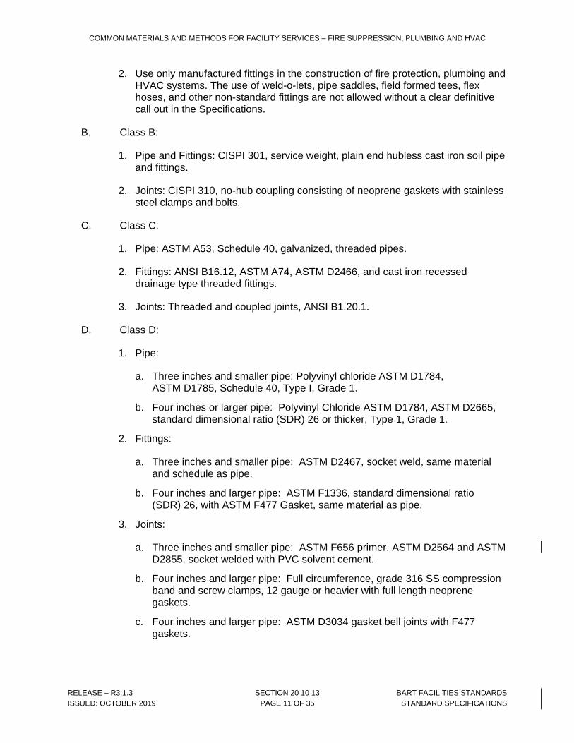
2. Use only manufactured fittings in the construction of fire protection, plumbing and HVAC systems. The use of weld-o-lets, pipe saddles, field formed tees, flex hoses, and other non-standard fittings are not allowed without a clear definitive call out in the Specifications.
B. Class B:
1. Pipe and Fittings: CISPI 301, service weight, plain end hubless cast iron soil pipe and fittings.
2. Joints: CISPI 310, no-hub coupling consisting of neoprene gaskets with stainless steel clamps and bolts.
C. Class C:
1. Pipe: ASTM A53, Schedule 40, galvanized, threaded pipes.
2. Fittings: ANSI B16.12, ASTM A74, ASTM D2466, and cast iron recessed drainage type threaded fittings.
3. Joints: Threaded and coupled joints, ANSI B1.20.1.
D. Class D:
1. Pipe:
a. Three inches and smaller pipe: Polyvinyl chloride ASTM D1784, ASTM D1785, Schedule 40, Type I, Grade 1.
b. Four inches or larger pipe: Polyvinyl Chloride ASTM D1784, ASTM D2665, standard dimensional ratio (SDR) 26 or thicker, Type 1, Grade 1.
2. Fittings:
a. Three inches and smaller pipe: ASTM D2467, socket weld, same material and schedule as pipe.
b. Four inches and larger pipe: ASTM F1336, standard dimensional ratio (SDR) 26, with ASTM F477 Gasket, same material as pipe.
3. Joints:
a. Three inches and smaller pipe: ASTM F656 primer. ASTM D2564 and ASTM D2855, socket welded with PVC solvent cement.
b. Four inches and larger pipe: Full circumference, grade 316 SS compression band and screw clamps, 12 gauge or heavier with full length neoprene gaskets.
c. Four inches and larger pipe: ASTM D3034 gasket bell joints with F477 gaskets.
COMMON MATERIALS AND METHODS FOR FACILITY SERVICES – FIRE SUPPRESSION, PLUMBING AND HVAC
RELEASE – R3.1.3 SECTION 20 10 13 BART FACILITIES STANDARDS
ISSUED: OCTOBER 2019 PAGE 12 OF 35 STANDARD SPECIFICATIONS
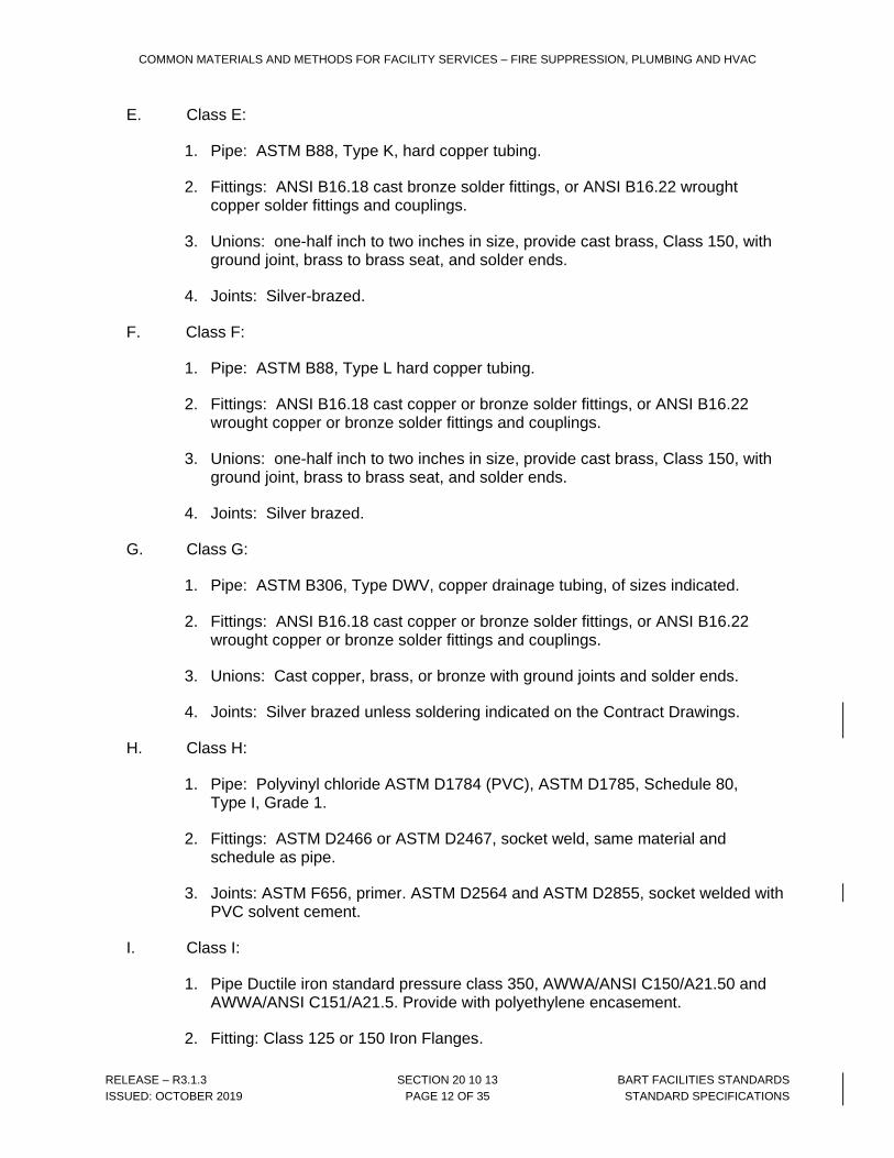
E. Class E:
1. Pipe: ASTM B88, Type K, hard copper tubing.
2. Fittings: ANSI B16.18 cast bronze solder fittings, or ANSI B16.22 wrought copper solder fittings and couplings.
3. Unions: one-half inch to two inches in size, provide cast brass, Class 150, with ground joint, brass to brass seat, and solder ends.
4. Joints: Silver-brazed.
F. Class F:
1. Pipe: ASTM B88, Type L hard copper tubing.
2. Fittings: ANSI B16.18 cast copper or bronze solder fittings, or ANSI B16.22 wrought copper or bronze solder fittings and couplings.
3. Unions: one-half inch to two inches in size, provide cast brass, Class 150, with ground joint, brass to brass seat, and solder ends.
4. Joints: Silver brazed.
G. Class G:
1. Pipe: ASTM B306, Type DWV, copper drainage tubing, of sizes indicated.
2. Fittings: ANSI B16.18 cast copper or bronze solder fittings, or ANSI B16.22 wrought copper or bronze solder fittings and couplings.
3. Unions: Cast copper, brass, or bronze with ground joints and solder ends.
4. Joints: Silver brazed unless soldering indicated on the Contract Drawings.
H. Class H:
1. Pipe: Polyvinyl chloride ASTM D1784 (PVC), ASTM D1785, Schedule 80, Type I, Grade 1.
2. Fittings: ASTM D2466 or ASTM D2467, socket weld, same material and schedule as pipe.
3. Joints: ASTM F656, primer. ASTM D2564 and ASTM D2855, socket welded with PVC solvent cement.
I. Class I:
1. Pipe Ductile iron standard pressure class 350, AWWA/ANSI C150/A21.50 and AWWA/ANSI C151/A21.5. Provide with polyethylene encasement.
2. Fitting: Class 125 or 150 Iron Flanges.
COMMON MATERIALS AND METHODS FOR FACILITY SERVICES – FIRE SUPPRESSION, PLUMBING AND HVAC
RELEASE – R3.1.3 SECTION 20 10 13 BART FACILITIES STANDARDS
ISSUED: OCTOBER 2019 PAGE 13 OF 35 STANDARD SPECIFICATIONS
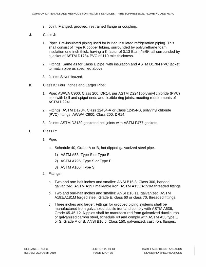
3. Joint: Flanged, grooved, restrained flange or coupling.
J. Class J:
1. Pipe: Pre-insulated piping used for buried insulated refrigeration piping. This shall consist of Type K copper tubing, surrounded by polyurethane foam insulation one inch thick, having a K factor of 0.13 Btu in/hr/ft2, all surrounded by a jacket of ASTM D1784 PVC of 110 mils thickness.
2. Fittings: Same as for Class E pipe, with insulation and ASTM D1784 PVC jacket to match pipe as specified above.
3. Joints: Silver-brazed.
K. Class K: Four Inches and Larger Pipe:
1. Pipe: AWWA C900, Class 200, DR14, per ASTM D2241polyvinyl chloride (PVC) pipe with bell and spigot ends and flexible ring joints, meeting requirements of ASTM D2241.
2. Fittings: ASTM D1784, Class 12454-A or Class 12454-B, polyvinyl chloride (PVC) fittings, AWWA C900, Class 200, DR14.
3. Joints: ASTM D3139 gasketed bell joints with ASTM F477 gaskets.
L. Class R:
1. Pipe:
a. Schedule 40, Grade A or B, hot dipped galvanized steel pipe.
1) ASTM A53, Type S or Type E.
2) ASTM A795, Type S or Type E.
3) ASTM A106, Type S.
2. Fittings:
a. Two and one-half inches and smaller: ANSI B16.3, Class 300, banded, galvanized, ASTM A197 malleable iron, ASTM A153/A153M threaded fittings.
b. Two and one-half inches and smaller: ANSI B16.11, galvanized, ASTM A181/A181M forged steel, Grade E, class 60 or class 70, threaded fittings.
c. Three inches and larger: Fittings for grooved piping systems shall be manufactured from galvanized ductile iron and comply with ASTM A536, Grade 65-45-12. Nipples shall be manufactured from galvanized ductile iron or galvanized carbon steel, schedule 40 and comply with ASTM A53 type E or S, Grade A or B. ANSI B16.5, Class 150, galvanized, cast iron, flanges.
COMMON MATERIALS AND METHODS FOR FACILITY SERVICES – FIRE SUPPRESSION, PLUMBING AND HVAC
RELEASE – R3.1.3 SECTION 20 10 13 BART FACILITIES STANDARDS
ISSUED: OCTOBER 2019 PAGE 14 OF 35 STANDARD SPECIFICATIONS
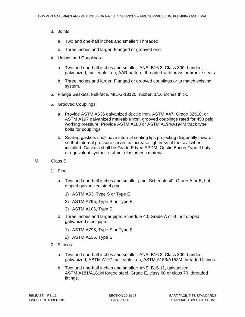
3. Joints:
a. Two and one-half inches and smaller: Threaded.
b. Three inches and larger: Flanged or grooved end.
4. Unions and Couplings:
a. Two and one-half inches and smaller: ANSI B16.3, Class 300, banded, galvanized, malleable iron, AAR pattern, threaded with brass or bronze seats.
b. Three inches and larger: Flanged or grooved couplings or to match existing system.
5. Flange Gaskets: Full-face, MIL-G-13120, rubber, 1/16 inches thick.
6. Grooved Couplings:
a. Provide ASTM A536 galvanized ductile iron, ASTM A47, Grade 32510, or ASTM A197 galvanized malleable iron, grooved couplings rated for 450 psig working pressure. Provide ASTM A183 or ASTM A194/A194M track type bolts for couplings.
b. Sealing gaskets shall have internal sealing lips projecting diagonally inward so that internal pressure serves to increase tightness of the seal when installed. Gaskets shall be Grade E type EPDM, Gustin Bacon Type II butyl, or equivalent synthetic-rubber elastomeric material.
M. Class S:
1. Pipe:
a. Two and one-half inches and smaller pipe: Schedule 40, Grade A or B, hot dipped galvanized steel pipe.
1) ASTM A53, Type S or Type E.
2) ASTM A795, Type S or Type E.
3) ASTM A106, Type S.
b. Three inches and larger pipe: Schedule 40, Grade A or B, hot dipped galvanized steel pipe.
1) ASTM A795, Type S or Type E.
2) ASTM A135, Type E.
2. Fittings:
a. Two and one-half inches and smaller: ANSI B16.3, Class 300, banded, galvanized, ASTM A197 malleable iron, ASTM A153/A153M threaded fittings.
b. Two and one-half inches and smaller: ANSI B16.11, galvanized, ASTM A181/A181M forged steel, Grade E, class 60 or class 70, threaded fittings.
COMMON MATERIALS AND METHODS FOR FACILITY SERVICES – FIRE SUPPRESSION, PLUMBING AND HVAC
RELEASE – R3.1.3 SECTION 20 10 13 BART FACILITIES STANDARDS
ISSUED: OCTOBER 2019 PAGE 15 OF 35 STANDARD SPECIFICATIONS
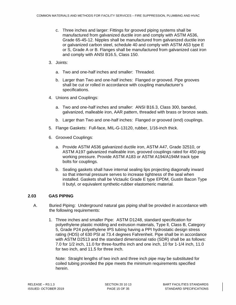
c. Three inches and larger: Fittings for grooved piping systems shall be manufactured from galvanized ductile iron and comply with ASTM A536, Grade 65-45-12. Nipples shall be manufactured from galvanized ductile iron or galvanized carbon steel, schedule 40 and comply with ASTM A53 type E or S, Grade A or B. Flanges shall be manufactured from galvanized cast iron and comply with ANSI B16.5, Class 150.
3. Joints:
a. Two and one-half inches and smaller: Threaded.
b. Larger than Two and one-half inches: Flanged or grooved. Pipe grooves shall be cut or rolled in accordance with coupling manufacturer’s specifications.
4. Unions and Couplings:
a. Two and one-half inches and smaller: ANSI B16.3, Class 300, banded, galvanized, malleable iron, AAR pattern, threaded with brass or bronze seats.
b. Larger than Two and one-half inches: Flanged or grooved (end) couplings.
5. Flange Gaskets: Full-face, MIL-G-13120, rubber, 1/16-inch thick.
6. Grooved Couplings:
a. Provide ASTM A536 galvanized ductile iron, ASTM A47, Grade 32510, or ASTM A197 galvanized malleable iron, grooved couplings rated for 450 psig working pressure. Provide ASTM A183 or ASTM A194/A194M track type bolts for couplings.
b. Sealing gaskets shall have internal sealing lips projecting diagonally inward so that internal pressure serves to increase tightness of the seal when installed. Gaskets shall be Victaulic Grade E type EPDM, Gustin Bacon Type II butyl, or equivalent synthetic-rubber elastomeric material.
2.03 GAS PIPING
A. Buried Piping: Underground natural gas piping shall be provided in accordance with the following requirements:
1. Three inches and smaller Pipe: ASTM D1248, standard specification for polyethylene plastic molding and extrusion materials, Type ll, Class B, Category 5, Grade P24 polyethylene IPS tubing having a PPI hydrostatic design stress rating (HDS) of 630 PSI at 73.4 degrees Fahrenheit. Pipe shall be in accordance with ASTM D2513 and the standard dimensional ratio (SDR) shall be as follows: 7.0 for 1/2 inch, 11.0 for three-fourths inch and one inch, 10 for 1-1/4 inch, 11.0 for two inch, and 11.5 for three inch.
Note: Straight lengths of two inch and three inch pipe may be substituted for coiled tubing provided the pipe meets the minimum requirements specified herein.

COMMON MATERIALS AND METHODS FOR FACILITY SERVICES – FIRE SUPPRESSION, PLUMBING AND HVAC
RELEASE – R3.1.3 SECTION 20 10 13 BART FACILITIES STANDARDS
ISSUED: OCTOBER 2019 PAGE 16 OF 35 STANDARD SPECIFICATIONS
2. 4 inches and larger pipe: ASTM D1248 and ASTM D2513, polyethylene pipe having a PPI HDS of 630 psi at 73.4 degrees Fahrenheit, and having 11.5 SDR.
3. Fittings all sizes: ASTM D2513 and ASTM D2683, polyethylene socket weld, confirming to ASTM-2683.
4. Joints: Socket weld only.
5. Meter Risers: Schedule 40 black steel pipe, epoxy-coated, meeting requirements of ASTM D2513 and D.O.T. 192-283 CSA approved and IAMPO listed, transition riser with double “O” ring seal transition fitting for polyethylene piping connection.
B. Above Grade Piping: Black steel, schedule 80 pipe, with threaded, Class 300 malleable iron fittings and ground joint unions up 2-1/2 inches, and Class 300 flanged for 3 inches and larger pipe, meeting District and jurisdictional authority standards.
2.04 DIESEL EXHAUST PIPE
A. Pipe: Provide factory-built double wall pipe. Outer jacket shall be aluminum coated steel 0.025 inches thick and inner pipe shall be Type 304 or Type 316 stainless steel 0.035 inches thick. Provide air gap of one-inch minimum between pipe and jacket. Pipe shall be laboratory tested, classified, and listed by a nationally recognized testing agency.
B. Fittings: Provide manufacturer’s standard fittings and installation accessories for use with specified pipe. Provide special fittings as indicated.
C. Joints: Pipe joints shall be sealed by use of V-bands and high temperature joint cement as recommended by the pipe manufacturer.
2.05 HYDRAULIC PIPING FOR ELEVATORS
A. Provide hydraulic line between Elevator Machine Room and Hoistway Pits, as indicated. If embedded, wrap lines as indicated.
1. Pipe: ASTM A53, Schedule 80, black steel. Pipe shall exhibit a 30-degree bevel angle at the welded ends.
2. Fittings 2 inches and smaller: ASTM A105, Grade ll, and ANSI B16.11, 2000 pound forged steel threaded fittings.
3. Fittings 2-1/2 inches and larger: ASTM A234, and ANSI B16.9, standard weight, butt-welding fittings.
4. Joints 2 inches and smaller: Threaded and coupled.
5. Joints 2 1/2 inches and larger: Butt-welded.
6. Union 2 inches and smaller: ASTM A105, ANSI 16.11 – 2000 pound socket weld with ground joints.
COMMON MATERIALS AND METHODS FOR FACILITY SERVICES – FIRE SUPPRESSION, PLUMBING AND HVAC
RELEASE – R3.1.3 SECTION 20 10 13 BART FACILITIES STANDARDS
ISSUED: OCTOBER 2019 PAGE 17 OF 35 STANDARD SPECIFICATIONS
7. Unions 2 1/2 inches and larger: Flanged.
8. Flanges: ANSI B16.5 and ASTM A181, Grade I, forged raised or insert face, 150-pound class, slip-on or weld neck to suit work site conditions.
B. Provide 1/2 inch diameter hydraulic scavenger (oil return) line between Elevator Machine Rooms and Hoistway Pits, where indicated.
1. Pipe: ASTM A53, Schedule 40, black steel, screwed.
2. Fittings: Threaded, ANSI B16.12, Schedule 40.
2.06 HYDRONIC PIPING AND SPECIALTIES
A. Condensate, Condenser, Heating, and Chilled Water Piping; Buried
1. Steel Pipe: ASTM A53/A53M, Schedule 40, for 6 inch and larger sized, black with AWWA C105 Polyethylene jacket.
a. Fittings: ANSI/B16.5 black, forged steel or ASME B16.3 malleable iron fitting, threaded. ASTM A536 black, ductile iron or ASTMS 197 black malleable iron grooved and coupling. All buried fittings to be provided with AWWA C105 Polyethylene jackets.
b. Joints: Welded
2. Copper Tubing: ASTM B88/B88M, Type K. annealed for 4 inch and smaller size
a. Fittings: ASME B16.22, wrought copper
b. Joints: Solder, lead free, ASTM B32, 95-5 tin-antimony, or tin and silver, with melting range 430 to 535 degrees Fahrenheit.
B. Condensate, Condenser, Heating and Chilled Water Piping; Above Ground
1. Steel Pipe: ASTM A53/A53M. Schedule 40, galvanized for two inch or smaller
a. Fittings: ASME B16.3, malleable iron or ASTM A234/A234M, forged steel threaded, type galvanized.
b. Joints: Threaded for pipe 2 inch and smaller.
2. Steel Pipe; ASTM A53/A53M, Schedule 40, grooved ends galvanized 2 1/2 inches and larger.
a. Fittings: ASTM A395/A395M and ASTM A536 galvanized ductile iron, grooved ends.
b. Joints: Grooved mechanical couplings meeting ASTM F1476.
1) Housing Clamps: ASTM A395/A395M and ASTM A536 ductile iron type.
2) Gasket: Elastomer composition for operating temperature range from 86 degrees Fahrenheit to 230 degrees Fahrenheit.
COMMON MATERIALS AND METHODS FOR FACILITY SERVICES – FIRE SUPPRESSION, PLUMBING AND HVAC
RELEASE – R3.1.3 SECTION 20 10 13 BART FACILITIES STANDARDS
ISSUED: OCTOBER 2019 PAGE 18 OF 35 STANDARD SPECIFICATIONS
3) Accessories: Steel bolts, nuts, and washers.
3. Copper Tubing: ASTM B88 Type K, hard drawn 2 1/2 inches and larger.
a. Fittings ASME B16.18, cast brass, solder wrought copper.
b. Tee Connections: Mechanically extracted collars with notched and dimpled branch tube.
c. Joints: Solder, lead free, ASTM B32, 95-5 tin-antimony, or tin and silver, with melting range 430 to 535 degrees Fahrenheit.
C. Automatic Air Vent: Designed to vent automatically with float principle; bronze body and nonferrous internal parts; 150 psig working pressure, 250 degree Fahrenheit operating temperature, with 1/4 inch discharge connection and 1/2 inch inlet connection. Provide 1/2 inch ball valve at each air vent to permit service of air vent.
D. Pump Suction Diffusers: Angle or straight pattern, pump inlet fitting, 175 psig pressure rating; cast iron body and end cap. Include bronze start-up and stainless steel permanent strainers; stainless steel straightening vanes; drain plug; and factory fabricated support.
E. Expansion Tank: Provide welded steel expansion tank, size and capacity as indicated. Tank shall be fitted with lifting rings, seismic anchorage and skirt as required. Fitting connections shall be same as for pipe. Provide sight glass. Paint tank with two coats of primer.
F. Air Separator: Provide external air separation unit with integral system strainer as indicated. Strainer shall be removable, of stainless steel, with 3/16 inch diameter perforations, and shall have a free area of not less than five times the cross sectional area of the connecting pipe. Provide seismic anchorage. Provide blow down connection. Paint separator with two coats of primer.
G. Valve Applications: General-Duty Valve Applications: Unless otherwise indicated, use the following valve types:
1. Shutoff Duty: Gate and ball.
2. Throttling Duty: Globe and butterfly valves.
H. Provide welded threadolets for temperature and pressure gages.
I. Provide separable wells and flow switches in accordance with Section 23 09 00, Instrumentation and Control for HVAC. Coordinate sizes and locations with Section 23 09 00, Instrumentation and Control for HVAC.
COMMON MATERIALS AND METHODS FOR FACILITY SERVICES – FIRE SUPPRESSION, PLUMBING AND HVAC
RELEASE – R3.1.3 SECTION 20 10 13 BART FACILITIES STANDARDS
ISSUED: OCTOBER 2019 PAGE 19 OF 35 STANDARD SPECIFICATIONS
2.07 BRANCH OUTLETS
A. Refrigeration Piping: Wrought copper tees, Schedule 80, soldered.
B. Copper Tubing: Manufactured brazing Tees, with branch size at least two sizes smaller than the main or cast bronze tees.
C. Threaded, steel piping and socket-weld PVC piping. Provide tees as specified under Article 2.01.
2.08 PIPE JOINT MATERIAL
A. Silver Brazing Alloy: Comply with AWS A5.8 requirements, Class BAg-1 for 1100 degrees Fahrenheit to 1500 degrees Fahrenheit melting temperature.
B. Solder: ASTM B32, Grade 95 TA, up to 250 degrees Fahrenheit.
C. Arc-Welding Electrodes: AWS A5.1 through AWS A5.29, as applicable.
D. Welding Rods for Oxyacetylene Welding: AWS A5.2.
2.09 GASKETS
A. For joints in soil, waste, vent, and drain piping, provide polychloroprene rubber cellular elastomeric preformed gasket and compatible sealing material as required for type of piping material used.
2.10 INSULATING CONNECTIONS
A. For two inches and Smaller Piping: Provide insulating joints that consist of a three-inch minimum length of threaded dielectric nipple pipe and dielectric unions or flanges at both ends. The unions shall be of two dissimilar metal parts with dielectric gasket.
B. For two and one-half inches and Larger Piping: Provide dielectric insulating flanges constructed so that two pipes being connected are completely insulated from each other with no metal-to-metal contact. The flanges shall be galvanized and shall be made up with complete insulating components consisting of a dielectric gasket, bolt insulator sleeves, and bolt washers.
2.11 EXPANSION JOINTS
A. Pressure Rating: 150-psig minimum at 250 degrees Fahrenheit.
B. Type: Flanged, stainless steel, consisting of a corrugated bellows, capable of absorbing pipe movement in an axial or lateral direction. Provide with support rods to keep flange faces parallel during installation.
COMMON MATERIALS AND METHODS FOR FACILITY SERVICES – FIRE SUPPRESSION, PLUMBING AND HVAC
RELEASE – R3.1.3 SECTION 20 10 13 BART FACILITIES STANDARDS
ISSUED: OCTOBER 2019 PAGE 20 OF 35 STANDARD SPECIFICATIONS
C. Pipe-Alignment Guides: As recommended by the pipe joint manufacturer but not more than five feet on each side of each expansion joint, except in lines four inches or smaller, they may be not over two feet each side of the joint.
D. Traverse Capacity of Joint: Not less than indicated.
E. Provide 4-way bracing on each side of the joint.
2.12 Y-TYPE STRAINERS
A. Strainer Requirements: Provide strainers full line size of connecting piping, 175 psig WOG pressure rating, with 304 series stainless steel 60 mesh screen, ASTM A126, Class B.
B. Two inches and Smaller: Brass or bronze body, threaded connections, screwed screen retainer, with centered blow down fitting and gate valve of the same size as blow off tapping.
C. Two and one-half inches and Larger: Cast-iron body, flanged connections, bolted screen retainer with off-center blow down fitting and gate valve of the same size as blow off tapping.
2.13 GAGES AND TEST PLUGS
A. Test Plug: At each side, provide a 1/4-inch female NPT adapter for test gages conforming with FS GG-G-76. Provide captive spring-loaded ball check in stainless steel housing with male thread for installation in threaded tee for locations indicated.
B. Gages: Operating range of gages shall be approximately 150 percent of indicated operating service pressure or 200 psig, whichever is greater. Draft gages for HVAC air filter shall be differential type calibrated 0.10 to 1 inch of water column.
1. Calibration: Calibrated to two percent in middle one-third of dial range and equipped with means of front calibration.
2. Movements: Phosphor-bronze bushed, rotary type.
3. Panel Mounted: Flush mounting type in cast iron or aluminum cases.
4. Stem or Pipe Mounted: Flangeless cases of drawn or stamped steel, or aluminum.
C. Pressure-Differential Gages: Draft gages for HVAC air filter banks shall be pressure differential type with a calibrated range of 0.10 to 1 inch of water column.
2.14 THERMOMETERS
A. Requirements: Thermometer case, stem and bulb chamber will be constructed of die cast aluminum. Protective lens material should be either shatter proof glass or polycarbonate. A high magnification glass tube filled with non-toxic colored liquid
COMMON MATERIALS AND METHODS FOR FACILITY SERVICES – FIRE SUPPRESSION, PLUMBING AND HVAC
RELEASE – R3.1.3 SECTION 20 10 13 BART FACILITIES STANDARDS
ISSUED: OCTOBER 2019 PAGE 21 OF 35 STANDARD SPECIFICATIONS
shall be used. The scale will have a maximum of two degrees between graduations and 20 degrees between figures. The scale range shall be 150 percent of the normal operating process temperature of the system with an upper limit of 300 degrees Fahrenheit. A brass separable socket shall be provided.
B. Scale Lengths: Seven inches minimum for tanks and similar equipment, and five inches minimum for piping.
C. Optional: Provide dial thermometer with 5 inch dials and liquid-filled thermal systems.
2.15 ACCESS DOORS AND PANELS
A. Access Requirements: Provide manufactured or prefabricated wall and ceiling access panels for service access to equipment and valves. Comply with requirements of Section 08 31 00, Access Doors and Panels. For access doors and panels in sheet metal ductwork and plenums, refer to Section 23 31 00, HVAC Ducts and Casings, for requirements.
B. Size: Large enough to permit removal of equipment, but not less than 12 inches by 12 inches net opening. Where entrance of service person is required, provide minimum opening of 24 inches by 24 inches.
C. Construction: Refer to Section 08 31 00, Access Doors and Panels, for requirements.
2.16 PIPE SLEEVES
A. Pipe sleeves and seals shall comply with applicable requirements of Section 20 20 13, Pipe Sleeves, Supports and Anchors for Facility Services.
2.17 CASINGS
A. Casing Requirements: Provide minimum black steel pipe conforming to ASTM A53, Schedule 40, with polyethylene encasement in accordance with AWWA C105.
B. Casing Insulators: High-density, injection-molded polyethylene casing insulator having the following properties:
1. Compressive strength (ASTM D695) 3200 psi
2. Tensile strength (ASTM D638, ASTM D651) 3100 - 5500 psi
3. Water absorption (ASTM D570) 0.1 percent
4. Impact strength (ASTM D256) 1.5 to 4.0 ft-lb/in. of notch
C. Casing End Seals:
1. Provide modular type mechanical casing seals consisting of interlocking synthetic rubber links shaped to fill the annular space between the pipe and casing and
COMMON MATERIALS AND METHODS FOR FACILITY SERVICES – FIRE SUPPRESSION, PLUMBING AND HVAC
RELEASE – R3.1.3 SECTION 20 10 13 BART FACILITIES STANDARDS
ISSUED: OCTOBER 2019 PAGE 22 OF 35 STANDARD SPECIFICATIONS
nonconductive pressure plates, with stainless steel compression bolts (T-head type) and nuts. Seals shall be sized in accordance with the manufacturer’s requirements for the particular size of carrier pipe and casing involved to obtain a watertight seal and withstand indicated test pressure for casing.
2. Modular type mechanical seals for metallic carrier pipe inside a metallic casing shall be an insulating type designed to provide electrical isolation between the carrier pipe and casing.
2.18 VALVES
A. Approved Valves: For wet standpipe and fire protection sprinkler systems, valves shall be listed and approved by nationally recognized agencies for intended service and shall bear stamp or label of the agency. The main isolation valve shall be located inside the building at the utility entrance and shall be an OS&Y valve.
B. Gate Valves:
1. Two inches and Smaller in Diameter: 150 pound, bronze body, bronze trim, rising stem, wedge disc, union bonnet, threaded connection, conforming with requirements of MSS SP-80.
2. Two and one-half inches and Larger in Diameter: 125 pound, except 175 pounds for use on wet standpipe and fire protection sprinkler systems, cast iron body, bronze trim, bolted bonnet, rising stem, solid wedge disc, hand wheel, outside screw and yoke, flanged connection, provide chain wheel operators for valves 6 inches and larger mounted 8 feet above floor, conforming with requirements of MSS SP-70.
C. Globe Valves:
1. Two inches and Smaller in diameter: 150 pound (except 175 pound for use on fire protection systems), bronze body, bronze trim, rising stem, EDPM disc, bronze disk holder, screw bonnet, threaded connection, conforming with requirements of MSS SP-80.
2. Two and one-half inches and Larger in Diameter: 125 pound, except 175 pounds for use on wet standpipe and fire protection sprinkler systems, cast iron body, bronze trim, rising stem, plug-type disc, flanged connection, provide chain wheel operators for valves 6 inches and larger mounted 8 feet above floor, conforming with requirements of MSS SP-85.
D. Swing Check Valve:
1. Two inches and Smaller in Diameter: 150 pound, bronze body and cap, bronze seat, bronze threaded connection, with removable stainless steel hinge pin and screwed cap, suitable for operation in either horizontal or vertical position. Conform to requirements of MSS SP-80.
COMMON MATERIALS AND METHODS FOR FACILITY SERVICES – FIRE SUPPRESSION, PLUMBING AND HVAC
RELEASE – R3.1.3 SECTION 20 10 13 BART FACILITIES STANDARDS
ISSUED: OCTOBER 2019 PAGE 23 OF 35 STANDARD SPECIFICATIONS
2. Two and one-half inches and Larger in Diameter: 125 pound, cast iron body, Y-pattern, flanged connection with removable stainless steel hinge pin and bolted cap, cast iron disk, flanged end. Conform to requirements of MSS SP-71.
3. Fire Protection Use: Spring-loaded swing check valve with grooved ends, cast-iron body, stainless-steel seat, hinge pin, spring and clapper, and elastomeric seal, suitable for horizontal or vertical installation, and 250 psig working pressure.
E. Butterfly Valves: 150 pound except fire protection 300 psi wwp, body of ductile iron conforming to ASTM A395 and MSS SP-67, equipped with ASTM A582/A582M, stainless steel stem, EPDM encapsulated ductile iron disc, and EPDM “0” ring stem seals. The valve shall be assembled complete with a valve supervisory switch and a stem extension assembly. The stem extension shall have a hand crank and a reflectorized disc indicating valve disc position.
1. Where bronze valves are indicated or required, provide valves conforming to FS WW-V-1967.
F. Angle Hose Valves: Cast brass conforming to ASTM B62, rated for 300-psig non-shock service. Valves shall have fire department hose thread on discharge site, female NPT inlet, and shall be equipped with union bonnet, replaceable composition disc, and bronze stem. Hose valves shall be furnished with cast-bronze cap with chain attached to cap and valve, except the 1-1/2 inch angle hose valves installed in fire hose cabinets shall be connected to fire hose.
G. Air Release Valves: Cast-iron body with 300 series stainless-steel and bronze trim, combination air release and vacuum breaker type suitable for 300 psig working pressure.
H. Valve Supervisory Switch: Provide for post indicator valves, butterfly valves, and OS&Y gate valves for Fire Protection service only. Switches shall be mounted so as not to interfere with the normal operation of the valve and shall be adjusted to operate within two revolutions of the valve control or when the stem has moved no more than one-fifth of the distance from its normal position. The mechanism shall be internal in the gear operator of butterfly valve or contained in a weatherproof die cast metal housing that shall provide a 1/2-inch conduit entrance and incorporate the necessary facilities for attachment to the valve. The switch mechanism shall have a minimum rated capacity of 10 amps at 125/250 volts AC and 2.5 amps at 24 volts DC. The entire installed assembly shall be tamper-resistant.
I. Calibrated Plug Valves: 125 psig working pressure, 250 degree Fahrenheit maximum operating temperature, bronze body, plug valve with calibrated orifice. Provide with connections for portable differential pressure meter with integral check valves and seals. Valve shall have integral pointer and calibrated, scale to register degree of valve opening. Valves two-inch and smaller shall have threaded connections; valves two and one-half -inch and larger shall have flanged connections.
J. Not Used.
COMMON MATERIALS AND METHODS FOR FACILITY SERVICES – FIRE SUPPRESSION, PLUMBING AND HVAC
RELEASE – R3.1.3 SECTION 20 10 13 BART FACILITIES STANDARDS
ISSUED: OCTOBER 2019 PAGE 24 OF 35 STANDARD SPECIFICATIONS
K. Balancing Flow-Control Valves: Pressure independent Class 150, cast-iron housing, stainless- steel operating parts; threaded connections for two-inch and smaller, flanged connections for two and one-half -inch and larger. Factory set to automatically control flow rates within plus or minus five percent design, while compensating for system operating-pressure differential. Provide quick disconnect valves for flow measuring equipment. Provide metal identification tag with chain for each valve, factory marked with the zone identification valve model number and flow rate.
L. Triple-Duty Valves: Angle or straight pattern; 175 psig pressure rating; cast iron body; pump discharge fitting. Include drain plug, bronze-fitted shutoff, balancing and check valve features.
M. Pressure-Reducing Valves: MSS SP-80 valves two inches and smaller shall be all bronze construction meeting requirements of MSS SP-80. MSS-SP-85 valves Two and one-half ◦inches and larger shall be all cast iron construction meeting requirements of MSS SP-70. Valves two and one-half inches and smaller shall have threaded connections. Valves three inches and larger shall have flanged connections. Valves shall be stainless steel spring-loaded, single-seated, and suitable for tight shutoff under dead-end conditions. Provide with renewable stainless steel seat, nylon inserted diaphragm, and bolted spring chamber. Valves shall be rated for 300 psi working pressure, adjustable from 25 to 75 psi, factory set at 50 psi. Pressure gauges (or gauge ports) shall be installed upstream and downstream of the pressure- reducing valve.
N. Safety Relief Valves:
1. AGA Z21-22 and ASME BPVC Section IV, pressure and temperature relief valves shall be AGA design certified, ASME listed and rated, with bronze body, brass trim, stainless steel spring and silicone rubber seat disc. Pressure and temperature valves shall be installed on all water heaters and hot water storage tanks, rated for heating capacity of water heater.
2. Valves shall be ASME rated for intended service, and shall be single-seated, bronze body and trim, stainless steel spring, adjusting screw with cap and threaded connections for two and one-half inches and smaller valves, and flanged connections for three inches and larger valves.
O. Ball Valves: Two inches and Smaller: MSS SP 110, 400 pound one piece bronze body, chrome plated brass ball, regular port, teflon seats, blow-out proof stem, threaded ends with union.
P. Plug Valves: Two inches and Smaller: MSS SP 78, 150 pound, semi-steel construction, round port, full pipe area, pressure lubricated, teflon packing, threaded ends. Furnish one plug valve wrench for every ten plug-valves with minimum of one wrench.
COMMON MATERIALS AND METHODS FOR FACILITY SERVICES – FIRE SUPPRESSION, PLUMBING AND HVAC
RELEASE – R3.1.3 SECTION 20 10 13 BART FACILITIES STANDARDS
ISSUED: OCTOBER 2019 PAGE 25 OF 35 STANDARD SPECIFICATIONS
PART 3 – EXECUTION
3.01 INSTALLATION REQUIREMENTS
A. Protection of the Work:
1. Cover openings in ductwork, conduits, and piping, and temporarily seal openings to protect from contamination.
2. Protect materials and equipment from damage due to environmental conditions. Use protective cover, and protect from surface water by using raised platforms.
3. Protect unfinished work at the end of each workday from damage, contamination, and moisture by the use of plugs, caps, and covers, as applicable.
4. Protect piping and valves from damage pending performance of systems tests.
5. Protect installed thermometers and gauges from accidental damage by construction activity.
6. Following installation, and before final embedment, provide temporary protective covers and fixtures to prevent damage from traffic and overburden loads that may damage or displace embedments.
7. Clean fixtures, piping, valves, finished brass, and equipment installed under this work. Drain and flush piping to remove grease and foreign matter. Flush air and gas piping with compressed dry nitrogen.
B. Locations of Fixtures and Equipment:
1. The mechanical sheets of the Contract Drawings are diagrammatical and not intended for use in determining the exact locations of the components of mechanical and electrical systems.
2. Refer to applicable sheets of the Contract Drawings to determine the exact locations of fixtures and equipment to be installed as well as the locations of items or equipment indicated to be installed by others.
C. Provide seismic restraints, bracing, and anchors for piping and equipment in accordance with the requirements of Section 20 30 13, Vibration Isolation and Seismic Control for Facility Services.
D. Provide pipe sleeves, supports, and anchors in accordance with Section 20 20 13, Pipe Sleeves, Supports, and Anchors for Facility Services.
3.02 INSTALLATION OF PIPING
A. Install piping parallel to walls, floors, and ceilings, unless indicated otherwise. Clear obstructions, preserve headroom, and keep openings and passageways clear.
B. Ream pipe and tube ends. Remove burrs.
COMMON MATERIALS AND METHODS FOR FACILITY SERVICES – FIRE SUPPRESSION, PLUMBING AND HVAC
RELEASE – R3.1.3 SECTION 20 10 13 BART FACILITIES STANDARDS
ISSUED: OCTOBER 2019 PAGE 26 OF 35 STANDARD SPECIFICATIONS
C. Remove scale and dirt, inside and outside, before assembly.
D. Remove welding slag and foreign material from pipe and fitting materials.
E. Should structural features or other work prevent running of pipes or setting of equipment at locations indicated, minor deviations will be permitted, as approved by the Engineer.
F. Run piping in chases or recesses in walls where provided, through openings in floors, and in furred ceilings; otherwise, as exposed pipes. Do not embed piping in or below the structure, except as indicated.
G. Expanding or swaging of tubing to fit IPS fitting sockets will not be permitted.
H. Provide reducing fittings where change in pipe size occurs. Reducing bushings shall not be used unless otherwise indicated.
I. Provide couplings only where required pipe runs between fittings are longer than standard length of pipe being used.
J. Make changes in direction only with manufactured fittings.
K. Provide expansion loops (bends) where indicated.
L. Provide proper length bolts for each size flange on flanged connections. Bolts with excessive length of exposed threads will not be permitted. A minimum of three full threads is required to be exposed beyond the nut after tightening the assembly.
M. Prevent entry of foreign matter during handling, assembling, and installation. Use compressed air, wire brush, solvent, and other acceptable means to remove scale, dirt, and other foreign matter from interior of piping before final connections are made. Protect open ends of pipe by capping, plugging, or by other acceptable methods.
N. Anchor piping subject to expansion or contraction in a manner permitting such strains and stresses to be evenly distributed and alleviated by swing joints or expansion loops.
O. Provide unions or flanges in piping connections to equipment.
P. Install piping with sufficient pitch to ensure proper drainage and venting.
Q. Make exposed polished or enameled piping connections to fixtures or equipment to avoid damage to finished surfaces. Knurled pipe wrenches shall not be used on chrome-plated or polished stainless steel or aluminum tubing or equipment.
R. Electrically isolate connections between piping of dissimilar metals, between District-owned and non-District-owned piping, where pressure piping enters any structure not more than five feet from point of entry inside the structure, and where indicated.
COMMON MATERIALS AND METHODS FOR FACILITY SERVICES – FIRE SUPPRESSION, PLUMBING AND HVAC
RELEASE – R3.1.3 SECTION 20 10 13 BART FACILITIES STANDARDS
ISSUED: OCTOBER 2019 PAGE 27 OF 35 STANDARD SPECIFICATIONS
S. Install class of piping as indicated. Pressure pipe will not be permitted under concrete structures and building floor slabs.
T. Do not run water piping over electric switchboards, transformers, or electric motor starters.
3.03 INSTALLATION OF HYDRONIC PIPING AND SPECIALTIES
A. Hydronic Piping Valve Installation:
1. Install shutoff-duty valves at each branch connection to supply mains, at supply connections to each piece of equipment, and elsewhere as indicated.
2. Install throttling-duty valves at each branch connection to return mains, at return connections to each piece of equipment, and elsewhere as indicated.
3. Install calibrated balancing valves on the outlet of each heating or cooling element, and elsewhere as required to facilitate system balancing.
4. Install drain valves at low points in mains, risers, branch lines, and elsewhere as required for system drainage.
5. Install check valves on each pump discharge and elsewhere as required to control flow direction, unless triple-duty valves are indicated.
6. Install safety relief valves on hot water boilers and elsewhere as required by ASME Boiler and Pressure Vessel Code. Pipe discharge to floor without valves. Comply with ASME BPVC Section VIII, Division 1, for installation requirements.
B. Hydronic Piping Installation:
1. Install piping as specified in this Section.
2. Locate groups of pipes parallel to each other, and provide space to permit applying insulation and servicing of valves.
3. Install drains at low points in mains, risers, and branch lines consisting of a tee fitting, three-fourths inch NPS ball valve, and short three-fourths inch NPS threaded nipple and cap.
4. Install piping at a uniform grade of 0.2 percent upward in direction of flow.
5. Reduce pipe sizes using eccentric reducer fittings installed with level side up.
6. Install branch connections to mains using tee fittings in main with takeoff out from bottom of main line, except for up-feed risers with takeoff out from top of main line.
7. Install unions in pipes 2 inch NPS and smaller, adjacent to each valve, at final connections of each piece of equipment and elsewhere as indicated. Unions are not required at flanged connections.
COMMON MATERIALS AND METHODS FOR FACILITY SERVICES – FIRE SUPPRESSION, PLUMBING AND HVAC
RELEASE – R3.1.3 SECTION 20 10 13 BART FACILITIES STANDARDS
ISSUED: OCTOBER 2019 PAGE 28 OF 35 STANDARD SPECIFICATIONS
8. Install flanges on valves, apparatus, and equipment having 2-1/2 inch NPS and lager connections.
9. Install flexible connectors at inlet and discharge connections to pumps (except inline pumps) and other vibration-producing equipment.
10. Install strainers on supply side of each control valve, pressure-reducing valve, pressure-regulating valve, solenoid valve, in-line pump, and elsewhere as indicated. Install three-fourths-inch NPS nipple and ball valve in blow-down connection of strainers 2 inch NPS and larger.
11. Anchor piping to ensure proper direction of expansion and contraction.
12. Install welded threadolets for temperature and pressure control.
C. Hydronic Specialties Installation:
1. Install automatic air vents at high points in system, heat-transfer coils, and elsewhere as required for system air venting.
2. Install dip-tube fittings in boiler outlet. Run piping to expansion tank with a two percent upward slope toward tank. Connect boiler-outlet piping.
3. Chemical Feeders: Provide valved connections for chemical feeders. Permanent chemical feeders will be furnished by others. Provide temporary equipment for injection of initial chemical charge.
4. Install expansion tanks as indicated. Vent and purge air from hydronic system, and charge tank with proper air charge to suit system design requirements.
D. Terminal Equipment Connections:
1. Install control valves in accessible locations close to equipment.
2. Install bypass piping with ball or butterfly valve around control valve. Where multiple, parallel control valves are installed, only one bypass is required.
3. Install pressure gage at coil inlet connections.
E. Testing:
1. Use ambient temperature water as testing medium.
2. Use vents installed at the high points of system to release trapped air while filling system. Use drains installed at low points for complete removal of liquid.
3. Examine system to ensure that equipment and parts that cannot withstand test pressures are properly isolated. Examine test equipment to ensure that it is tight and that low-pressure filing lines are disconnected.
COMMON MATERIALS AND METHODS FOR FACILITY SERVICES – FIRE SUPPRESSION, PLUMBING AND HVAC
RELEASE – R3.1.3 SECTION 20 10 13 BART FACILITIES STANDARDS
ISSUED: OCTOBER 2019 PAGE 29 OF 35 STANDARD SPECIFICATIONS
4. Subject piping system to hydrostatic test pressure that is not less than 1.5 times the design pressure. Test pressure shall not exceed maximum pressure for any vessel, pump, valve, or other component in system under test. Check to verify that stress due to pressure at bottom of vertical runs does not exceed 90 percent of specified minimum yield strength or 1.7 times “SE” value in Appendix A of ASME B31.9.
5. After hydrostatic test pressure has been applied for at least 10 minutes, examine piping, joints, and connections for leakage. Eliminate leaks by tightening, repairing, or replacing components as appropriate, and repeat hydrostatic test until there are no leaks.
6. Prepare and submit written report of testing.
F. Adjusting and Cleaning:
1. After completing system installation, including outlet fittings and devices. inspect finish. Remove burrs, dirt, and construction debris, and repair damaged finishes including chips, scratches, and abrasions.
2. Fill the piping system with water and remove air. Flush each circulating system with an alkaline cleaning solution to remove grease and oil in the piping system. Solutions using trisodium phosphate shall be heated to temperatures of 160 degrees Fahrenheit to 180 degrees Fahrenheit. Other solutions may be submitted for approval. Drain and rinse with clean water.
3. Fill the piping system and remove air. Flush each circulating system with and acid cleaning solution to remove rust and scale. Apply solutions in accordance with manufacturer’s instructions. Drain and rinse with clean water.
4. Remove, clean, and replace strainer screens. After cleaning and flushing hydronic-piping system, but before balancing, remove disposable fine-mesh strainers in pump suction diffusers. Fill the piping system and remove air. Charge systems with initial chemical treatment as follows:
a. Heating, pH control, scale inhibitor, corrosion inhibitor, and conductivity controller.
5. Mark calibrated nameplates of pump discharge valves after hydronic system balancing has been completed, to permanently indicate final balanced position.
G. Commissioning:
1. Fill system and perform initial chemical treatment.
2. Check expansion tanks to determine that they are not air bound and that system is full of water.
3. Perform the following before operating the system:
a. Open valves to fully open position. Close coil bypass valves.

COMMON MATERIALS AND METHODS FOR FACILITY SERVICES – FIRE SUPPRESSION, PLUMBING AND HVAC
RELEASE – R3.1.3 SECTION 20 10 13 BART FACILITIES STANDARDS
ISSUED: OCTOBER 2019 PAGE 30 OF 35 STANDARD SPECIFICATIONS
b. Check pump for proper direction of rotation.
c. Set automatic fill valves for required system pressure.
d. Check air vents at high points of systems, and determine that all are installed and operating freely (automatic type).
e. Set temperature controls such that coils are calling for full flow.
f. Check operation of automatic bypass valves.
g. Check and set operating temperatures of boilers, chillers, and cooling towers to design requirements. Comply with requirements of Section 23 05 93, Testing, Adjusting, and Balancing for HVAC.
h. Lubricate motors and bearings.
3.04 INSTALLATION OF PIPE JOINTS AND CONNECTIONS
A. Installation Requirements:
1. Provide tool specifically designed for pipe cutting; debur all cut pipe ends. Make joints leak-tight. Test and remake leaky joints with new materials. Thread cement or calking shall not be used to remake leaky joints.
2. Do not use a sharp-toothed wrench in making up brass pipe or chrome-plated items.
3. Thread and length of threads shall be in accordance with applicable ANSI standards. Use a thread lubricant on male threads suitable for the proposed pipe service.
4. Soldered joints, ends of pipe, and insides of fittings shall be thoroughly cleaned and polished. Uniformly heat joint, and ensure capillary space is completely filled with solder, leaving a full bead of solder around the entire circumference of the joint.
5. Clean PVC pipe end with cleaning agent in accordance with manufacturer’s recommendations.
6. Welded pipe joints, qualification of welders, and testing shall be performed in accordance with AWS B21.3 or ASME Section VIII.
7. Provide a gasket coated with the gasket manufacturer’s recommended lubricant between the contact faces of the flanges.
8. Install hubless cast iron pipe, fittings, and joints in accordance with CISPI 301.
B. Copper Tubing Systems:
1. Use non-toxic silver-brazed joints for services specified. Flow nitrogen through tubing to prevent oxidation during brazing.
COMMON MATERIALS AND METHODS FOR FACILITY SERVICES – FIRE SUPPRESSION, PLUMBING AND HVAC
RELEASE – R3.1.3 SECTION 20 10 13 BART FACILITIES STANDARDS
ISSUED: OCTOBER 2019 PAGE 31 OF 35 STANDARD SPECIFICATIONS
2. Where soldering service is specified, make joints with 95-5 tin-antimony (SN95, SN94, E) solder per ASTM B32.
3. Clean outside of tube and inside of fitting at point of contact with fine grit carborundum sandpaper to a bright finish without deposits before joining. Take care to prevent over-heating of tube and fitting before joining. Before silver brazing, disassemble solder type valves used in refrigerant piping, and keep valve bodies cool by use of damp cloths or other approved methods.
4. The use of copper compression type fittings shall not be acceptable. Copper connections shall be threaded, soldered, or brazed only.
C. Steel Pipe and Welding Fittings:
1. Make joints in welded piping by oxyacetylene or electric arc process with welding continuous around pipe. Use qualified welders and welding procedures as specified in AWS B2.1.
2. Hydraulic piping welding shall use gas tungsten arc weld (GTAW) to root pass, using AWS ER70S-2 or ER70S-6 filler metal with argon purge. Shield metal arc weld (SMAW) the remaining weld to completion with AWS E7018 low hydrogen electrodes. Metal gas welding will not be permitted on hydraulic lines.
3. Welded branch outlets on galvanized steel pipe shall be cleaned of weld splatter, and all surfaces in the vicinity thereof shall be wire brushed and coated with a zinc rich painting system having a three mil DFT as specified in Section 09 91 00, Painting.
D. Polyvinyl Chloride (PVC) Pipe:
1. Threaded Joints: Make joints with Teflon pipe joint compound, or Teflon tape of type recommended by pipe and fitting manufacturer, suitable for service where it is to be used, conforming to ANSI B1.20.1.
2. Flanged Joints: When required, flanged joints may be used to connect to equipment or to other piping materials. Provide flanged, socket type molded PVC heavy-duty, 150-pound pattern, drilled in accordance with ANSI B16.5.
3. Socket Welded Joints: Use solvent cement of type recommended by the fitting manufacturer, suitable for service where it is to be used. Joints shall be made by workers skilled in technique of welding PVC pipe.
E. Steel Pipe and Grooved Couplings:
1. Flexible Couplings: Provide flexible grooved couplings for all piping systems routed through subway and U-wall trainway sections.
2. Rigid Couplings: Provide rigid grooved couplings for piping at all other locations as approved by the Engineer.
COMMON MATERIALS AND METHODS FOR FACILITY SERVICES – FIRE SUPPRESSION, PLUMBING AND HVAC
RELEASE – R3.1.3 SECTION 20 10 13 BART FACILITIES STANDARDS
ISSUED: OCTOBER 2019 PAGE 32 OF 35 STANDARD SPECIFICATIONS
F. Diesel Exhaust Pipe: Install as indicated and in accordance with the pipe manufacturer’s installation instructions.
3.05 INSTALLATION OF UNIONS, FLANGES, AND GASKETS
A. Unions: Provide unions where indicated and at each threaded or soldered connection to equipment, tanks, and valves, with the following exceptions:
1. Provide three unions at each three-way valve.
2. Only one union is required at each manually operated threaded valve.
3. In refrigerant piping systems, provide only where indicated.
B. Locations of Unions: Locate unions such that piping can be easily disconnected for removal of equipment, tank, or valve.
C. Flanges: Provide matching flange faces at each connection to equipment, tanks, and valves. Install gaskets of the required types.
3.06 INSTALLATION OF FLEXIBLE PIPE CONNECTIONS
A. Align and space piping accurately before installation. Do not use flexible connections to correct misalignment.
B. Support piping near equipment to prevent weight of pipe from compressing or extending flexible connection from required installed setting.
C. Install flexible connection as recommended by the connection manufacturer.
D. Assemble flexible section with metal retaining rings, built-in braided wire, built-in reinforcement with restriction bolts, or with wire-braid cover. Equip flanged assemblies with limit bolts to restrict maximum travel.
E. Provide control units for pipe connectors at equipment mounted on vibration isolators, to limit travel.
F. Provide pipe guides on each side of each expansion joint as recommended by the joint manufacturer. Provide four-way bracing on each side to maintain expansion capacity.
G. For expansion joints, provide joints with welded, flanged, or threaded ends, and bases for each joint unless otherwise indicated. Provide single-element joints with bases as an end anchor where indicated. Provide ball joints of stainless steel, malleable iron, ductile iron, carbon steel, bronze, or other alloys suitable for the service intended. Pre-compress expansion joints at time of installation in accordance with manufacturer’s installation instructions; and as required by actual temperature of pipe at time of installation.
COMMON MATERIALS AND METHODS FOR FACILITY SERVICES – FIRE SUPPRESSION, PLUMBING AND HVAC
RELEASE – R3.1.3 SECTION 20 10 13 BART FACILITIES STANDARDS
ISSUED: OCTOBER 2019 PAGE 33 OF 35 STANDARD SPECIFICATIONS
3.07 INSTALLATION OF GAGES
A. Requirements: Provide gages or test connections where indicated.
B. Labels: Install flexible aluminum-faced, black-plastic-backed indicating plate, three-fourths inch by three inches, with service engraved into black backing. Labels shall be mounted to gage body with stainless steel rivets.
C. Gage Cocks: Provide at each gage connection.
D. Gage Siphon: Install a gage siphon at each hot water gage.
3.08 INSTALLATION OF THERMOMETERS
A. Location and Type: Install thermometers to be easily read by a person standing on the floor of the room. Use straight, angle, or remote types to suit installation conditions.
B. Thermometers for Measuring Liquid Temperatures:
1. Install with extension necks or stems to suit insulation on pipes or the lining of tanks.
2. Install so bulb projects into flow stream and is completely immersed in liquid.
C. Labels: Install flexible aluminum-faced, black-plastic-backed indicating plate, three-fourths inch by three inches, with service engraved into black backing. Labels shall be mounted to gage body with stainless steel rivets.
3.09 INSTALLATION OF ACCESS DOORS AND PANELS
A. Required Locations: Provide access panels wherever valves, damper operators, fire dampers, gages, and similar items requiring servicing, adjustment, and inspection are concealed. Access panels are not required in furred or suspended ceilings with removable ceiling panels.
B. Door and Panel Types:
1. In Acoustical Tile Ceilings: Provide fill-in type, installed integral with tile pattern. Fill in with ceiling tile.
2. In Fire-Rated Ceilings: Provide fire-rated access panel, fill-in type or flat-faced, flush mounted panel as required.
3. Other Locations: Provide flat-faced flush mounted panel.
4. Provide plaster frame and grounds for plaster ceilings and walls.
C. Interface and Coordination: Refer to Section 08 31 00, Access Doors and Panels, for additional requirements
COMMON MATERIALS AND METHODS FOR FACILITY SERVICES – FIRE SUPPRESSION, PLUMBING AND HVAC
RELEASE – R3.1.3 SECTION 20 10 13 BART FACILITIES STANDARDS
ISSUED: OCTOBER 2019 PAGE 34 OF 35 STANDARD SPECIFICATIONS
3.10 INSTALLATION OF VALVES AND VALVE BOXES
A. Requirements: Provide valves at points indicated and specified, arranged to give complete and regulating control of piping systems. Provide valves full size of line, unless otherwise indicated. Install valves with neat appearance and grouping, so all parts are easily accessible for operation and maintenance. Install throttling flow valves where indicated, and on each circulating return branch on domestic hot water systems, on hot water heating systems, and on chilled water systems. Provide valve boxes for exterior valves for protection.
B. Stop Valves: Install stop valve or a compression stop on water supply lines to each plumbing fixture, including faucets and showers. Where required for accessibility, install them exposed adjacent to faucets. Where fixture trim is specified with integral built-in stops, individual supply stops will not be required. Union end fitting or union shall be installed downstream of stop valve.
C. Install valves with stems upright or horizontal, not inverted.
D. Install gate valves for shut-off and isolating service, to isolate equipment, part of system or vertical risers.
E. Provide drain valve at main shut-off valves and at low points of piping and apparatus.
F. Air Vent Valves: Manual Air Vent Assemblies: Provide where indicated and at high points to free piping system of air. Connect one-fourth inch copper tubing to top of high point, or other location, and extend down to easily accessible one-fourth-inch globe valve, mounted approximately five feet above floor, grouped and tagged. Discharge through one-fourth inch copper tubing to nearest floor drain or as approved by the Engineer.
G. Automatic Type Air Vent Valves: Provide and install as indicated with full sized copper tubing drain line from automatic valve to nearest floor drain or as approved by the Engineer.
H. Pressure Reducing Valves: Install reducing stations along walls or other available spaces with arrangement to permit easy access for servicing and removal of equipment. Provide union of flanged joints to permit springing pipe for valve removal. Provide a three-valve bypass at each pressure-reducing valve.
I. Chain Operators: Provide chain operators for valves, four inches and larger located overhead, seven feet or more above floor.
3.11 INSTALLATION OF PIPE AND VALVE IDENTIFICATION
A. Provide in accordance with Section 20 40 13, Identification for Facility Services.
COMMON MATERIALS AND METHODS FOR FACILITY SERVICES – FIRE SUPPRESSION, PLUMBING AND HVAC
RELEASE – R3.1.3 SECTION 20 10 13 BART FACILITIES STANDARDS
ISSUED: OCTOBER 2019 PAGE 35 OF 35 STANDARD SPECIFICATIONS
3.12 INSTALLATION OF EQUIPMENT
A. Place equipment in locations and spaces indicated. Move equipment into spaces through openings as required. Disassemble and reassemble equipment or other work necessary to accomplish this work.
B. Provide platforms and hangers as required for the installation of equipment.
C. Mount equipment on vibration isolation units, concrete inertia blocks, or concrete pads as indicated and in accordance with the approved Shop Drawings.
D. Install, align, and adjust equipment and vibration isolators in accordance with the respective manufacturer’s installation instructions and recommendations.
E. Provide mechanical equipment where indicated with V-belts and cast-iron machined and balanced V-groove sheaves. Key sheaves to shafts and lock with setscrews. On electric motors size NEMA 48 and smaller, fasten sheaves with hardened knurled cup point set screws against flat surface on shaft.
3.13 PAINTING
A. Except where otherwise indicated, piping systems, ductwork, and HVAC equipment shall not be painted. Where pipes, ductwork, and HVAC equipment are indicated to be painted, such as exposed items in finished rooms, prepare and paint as specified in Section 09 91 00, Painting. Copper, brass, bronze, and stainless items shall not be painted.
END OF SECTION 20 10 13