
A Quaternion-based Approach to Robot Arm...
54
A Quaternion-based Approach to Robot Arm Positioning J. Robert Buchanan Department of Mathematics 16 November 2006 J. Robert Buchanan A Quaternion-based Approach to Robot Arm Positioning
Transcript of A Quaternion-based Approach to Robot Arm...

A Quaternion-based Approach to Robot ArmPositioning
J. Robert Buchanan
Department of Mathematics
16 November 2006
J. Robert Buchanan A Quaternion-based Approach to Robot Arm Positioning

Outline
Coordinate frames
Euler angles and rotations in R3
Singularities
Robotic application
Quaternions and rotations in R3
Error analysis
J. Robert Buchanan A Quaternion-based Approach to Robot Arm Positioning

Aircraft Coordinate System: Body Frame
X
Y
Z
Body frame
J. Robert Buchanan A Quaternion-based Approach to Robot Arm Positioning
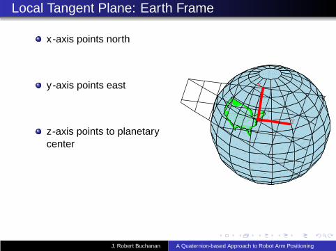
Local Tangent Plane: Earth Frame
x-axis points north
y -axis points east
z-axis points to planetarycenter
x
y
J. Robert Buchanan A Quaternion-based Approach to Robot Arm Positioning
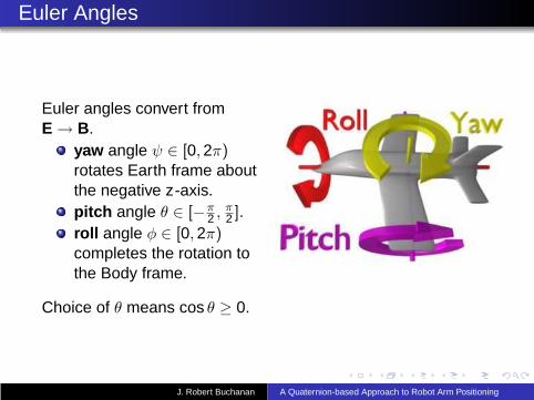
Euler Angles
Euler angles convert fromE → B.
yaw angle ψ ∈ [0,2π)rotates Earth frame aboutthe negative z-axis.pitch angle θ ∈ [−π
2 ,π2 ].
roll angle φ ∈ [0,2π)completes the rotation tothe Body frame.
Choice of θ means cos θ ≥ 0.
J. Robert Buchanan A Quaternion-based Approach to Robot Arm Positioning
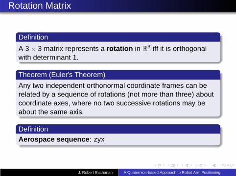
Rotation Matrix
Definition
A 3 × 3 matrix represents a rotation in R3 iff it is orthogonal
with determinant 1.
Theorem (Euler’s Theorem)
Any two independent orthonormal coordinate frames can berelated by a sequence of rotations (not more than three) aboutcoordinate axes, where no two successive rotations may beabout the same axis.
DefinitionAerospace sequence: zyx
J. Robert Buchanan A Quaternion-based Approach to Robot Arm Positioning

Single-angle Rotations
R = RxφRy
θRzψ where
Rxφ =
1 0 00 cosφ sinφ0 − sinφ cosφ
Ryθ =
cos θ 0 − sin θ0 1 0
sin θ 0 cos θ
Rzψ =
cosψ sinψ 0− sinψ cosψ 0
0 0 1
J. Robert Buchanan A Quaternion-based Approach to Robot Arm Positioning

Tracking Transformation
Imagine a telescope or radar following an aircraft which isinitially spotted on the horizon.
Definition
The tracking transformation is a rotation of the Earth’s localtangent plane through an angle ψ called the heading about thegeocentric z-axis and an angle θ called the elevation about thenew y -axis so that x-axis points at the remote object.
J. Robert Buchanan A Quaternion-based Approach to Robot Arm Positioning

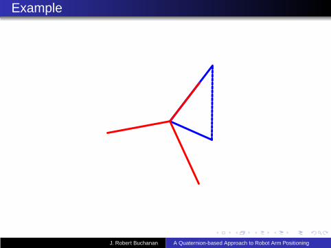
Example
J. Robert Buchanan A Quaternion-based Approach to Robot Arm Positioning

Example
J. Robert Buchanan A Quaternion-based Approach to Robot Arm Positioning
Example
J. Robert Buchanan A Quaternion-based Approach to Robot Arm Positioning
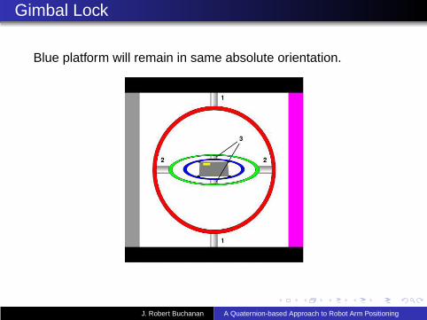
Gimbal Lock
Blue platform will remain in same absolute orientation.
J. Robert Buchanan A Quaternion-based Approach to Robot Arm Positioning
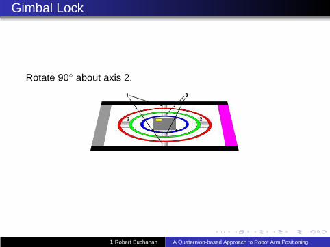
Gimbal Lock
Rotate 90◦ about axis 2.
J. Robert Buchanan A Quaternion-based Approach to Robot Arm Positioning
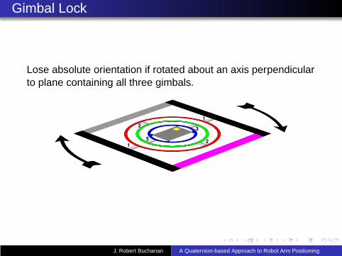
Gimbal Lock
Lose absolute orientation if rotated about an axis perpendicularto plane containing all three gimbals.
J. Robert Buchanan A Quaternion-based Approach to Robot Arm Positioning

Application
Control and positioning of a robot arm:
Sensors mounted in the arm measure position in Bodyframe.
Sensors consist of accelerometers (measuring GB) andmagnetometers (measuring HB).
Wish to convert this position and orientation to thelaboratory or Earth frame.
Conversion can be accomplished via rotations throughEuler angles or by use of a quaternion.
J. Robert Buchanan A Quaternion-based Approach to Robot Arm Positioning

Goals
Develop quaternion-based algorithm to convert data inbody frame to data in earth frame.
Implement algorithm in documented Matlab code.
Analyze errors in the Euler angles and quaternions asfunctions of input.
Implement various coordinate conversions in Matlab code.
J. Robert Buchanan A Quaternion-based Approach to Robot Arm Positioning
Input Data to Euler Angles
GB = RGE = R
00g
= g
− sin θsinφ cos θcosφ cos θ
=
GB1
GB2
GB3
thus
θ = − sin−1
(
GB1
g
)
.
Note: if θ = ±π2 then φ cannot be determined uniquely.
J. Robert Buchanan A Quaternion-based Approach to Robot Arm Positioning

When θ 6= ±π2 . . .
φ = tan−1
(
GB2
GB3
)
with sgn(φ) = sgn(GB2 ),
ψ = − tan−1
(
HB2 cosφ− HB
3 sinφ
HB1 cos θ + HB
2 sin θ sinφ+ HB3 sin θ cosφ
)
Note: ψ is determined up to ±π. Assuming HE1 ≥ 0 then
sgn(ψ) = −sgn(HB2 cosφ− HB
3 sinφ).
J. Robert Buchanan A Quaternion-based Approach to Robot Arm Positioning

Euler Angle Error Analysis
dθ = − dGB1
√
g2 − (GB1 )2
dφ =GB
3 dGB2 − GB
2 dGB3
(GB2 )2 + (GB
3 )2
dψ = −y2dy1 − y1dy2
y21 + y2
2
where
y1 = HB2 cosφ− HB
3 sinφ
y2 = HB1 cos θ + HB
2 sin θ sinφ+ HB3 sin θ cosφ
J. Robert Buchanan A Quaternion-based Approach to Robot Arm Positioning

Sir William Hamilton
In 1835 becamefascinated with therelationship between C
and the geometry of R2.
Wanted to extend thisidea to the geometry ofR
3.
On 16 October 1843discovered the algebra(4-dimensional) whichmade this possible.
J. Robert Buchanan A Quaternion-based Approach to Robot Arm Positioning
Brougham Bridge
J. Robert Buchanan A Quaternion-based Approach to Robot Arm Positioning

Brougham Bridge
J. Robert Buchanan A Quaternion-based Approach to Robot Arm Positioning

What are Quaternions?
Hypercomplex numbers of rank 4.
Non-commutative division ring.
Notation:
q = q0 + q1i + q2j + q3k
= q0 + q
where we will call
scalar part: q0
vector part: q
J. Robert Buchanan A Quaternion-based Approach to Robot Arm Positioning

Quaternion Arithmetic
Component-wise equality
Component-wise addition
Component-wise scalar multiplication (by real scalars)
Additive identity: 0
Additive inverse of q is denoted −q = −q0 − q1i− q2j− q3k
J. Robert Buchanan A Quaternion-based Approach to Robot Arm Positioning

Quaternion Multiplication
i2 = j2 = k2 = ijk = −1
ij = k = −ji
jk = i = −kj
ki = j = −ik
Thuspq = p0q0 − p · q
︸ ︷︷ ︸
scalar part
+ p0q + q0p + p × q︸ ︷︷ ︸
vector part
.
Multiplication is associative.
Multiplication is not commutative.
Multiplicative identity: 1 + 0.
Multiplication distributes over addition.
J. Robert Buchanan A Quaternion-based Approach to Robot Arm Positioning

Conjugates
The quaternionic conjugate is denoted q∗ and defined as
q∗ = (q0 + q)∗ = q0 − q.
Note: For all q ∈ H, q∗q = qq∗ ≥ 0.The norm of q is denoted |q| and defined as
|q| =√
q∗q =√
q20 + q2
1 + q22 + q2
3 .
J. Robert Buchanan A Quaternion-based Approach to Robot Arm Positioning
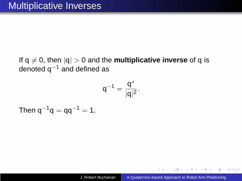
Multiplicative Inverses
If q 6= 0, then |q| > 0 and the multiplicative inverse of q isdenoted q−1 and defined as
q−1 =q∗
|q|2 .
Then q−1q = qq−1 = 1.
J. Robert Buchanan A Quaternion-based Approach to Robot Arm Positioning

Rotating with Quaternions
Goal: develop a linear operator based on quaternions whichrotates R
3 about a fixed vector in R3 through a specified angle.
If v ∈ R3 then the mapping v 7→ 0 + v takes v to a “pure”
quaternion. This mapping is an isomorphism between R3 and
the pure quaternions.Suppose the quaternion-based rotation has the form
qvr = (q0 + q)(0 + v)(r0 + r)
where q, r ∈ H.
J. Robert Buchanan A Quaternion-based Approach to Robot Arm Positioning
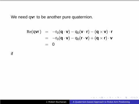
We need qvr to be another pure quaternion.
Re(qvr) = −r0(q · v) − q0(v · r) − (q × v) · r
= −r0(q · v) − q0(r · v) + (q × r) · v
= 0
if
J. Robert Buchanan A Quaternion-based Approach to Robot Arm Positioning
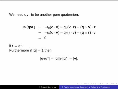
We need qvr to be another pure quaternion.
Re(qvr) = −r0(q · v) − q0(v · r) − (q × v) · r
= −r0(q · v) − q0(r · v) + (q × r) · v
= 0
if r = q∗.Furthermore if |q| = 1 then
|qvq∗| = |q||v||q∗| = |v|.
J. Robert Buchanan A Quaternion-based Approach to Robot Arm Positioning

Angle
The mapping v 7→ qvq∗ preserves the length of v, so it may bea rotation.Can we associate an angle with the mapping?
1 = |q|2
= q20 + ‖q‖2
= cos2 Φ + sin2 Φ
with Φ ∈ (−π, π].
Thus q = cos Φ +q‖q‖ sin Φ.
J. Robert Buchanan A Quaternion-based Approach to Robot Arm Positioning

Quaternion Rotation Operator
Definition
If q is a unit quaternion, the quaternion rotation operator Lq
is defined for v ∈ R3 as Lq(v) = qvq∗.
The quaternion rotation operator is a linear operator whichpreserves length.
J. Robert Buchanan A Quaternion-based Approach to Robot Arm Positioning

Main Rotation Result
Theorem
For any unit quaternion q = cos Φ +q‖q‖ sin Φ and for any
vector v ∈ R3 the action of Lq(v) = qvq∗ may be interpreted
geometrically as a rotation of vector v about vector q throughan angle of 2Φ.
J. Robert Buchanan A Quaternion-based Approach to Robot Arm Positioning
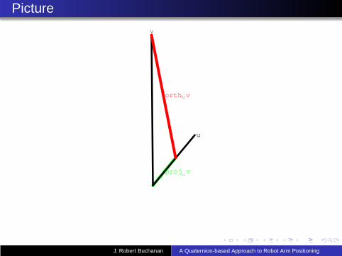
Picture
u
v
projuv
orthuv
J. Robert Buchanan A Quaternion-based Approach to Robot Arm Positioning

Proof
1 Let u =q‖q‖ .
2 Let v = projuv + orthuv.3 Note projuv = ku for some real scalar k .
Lq(ku) = kLq(u) = kquq∗ = ku
The vector projuv is invariant under Lq(·).
J. Robert Buchanan A Quaternion-based Approach to Robot Arm Positioning

Orthogonal Part
Let n = orthuv, then
Lq(n) = qnq∗
= (q20 − ‖q‖2)n + 2 (q · n)
︸ ︷︷ ︸
= 0
q + 2q0(q × n)
= (q20 − ‖q‖2)n + 2q0‖q‖ (
q‖q‖ × n)
︸ ︷︷ ︸
= n⊥
= (cos2 Φ − sin2 Φ)n + (2 sin Φ cos Φ)n⊥
= (cos 2Φ)n + (sin 2Φ)n⊥
J. Robert Buchanan A Quaternion-based Approach to Robot Arm Positioning

Proof (completed)
Since Lq(·) is a linear operator, then
Lq(v) = Lq(projuv + orthuv)
= Lq(projuv) + Lq(orthuv)
= projuv + (cos 2Φ)n + (sin 2Φ)n⊥
J. Robert Buchanan A Quaternion-based Approach to Robot Arm Positioning

Example
Example
Rotate v = 〈0,0,1〉 around r = 〈1,1,1〉 by 30◦.
q = cosπ
12+
1√3〈1,1,1〉 sin
π
12
Lq(v) =
⟨13,13− 1√
3,13
+1√3
⟩
J. Robert Buchanan A Quaternion-based Approach to Robot Arm Positioning
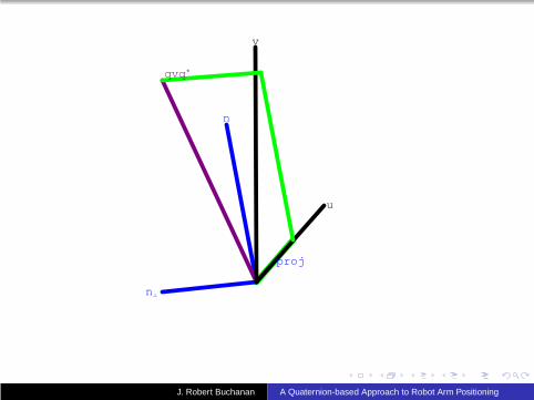
u
v
n
n¦
proj
qvq*
J. Robert Buchanan A Quaternion-based Approach to Robot Arm Positioning

u
v
qvq*
J. Robert Buchanan A Quaternion-based Approach to Robot Arm Positioning
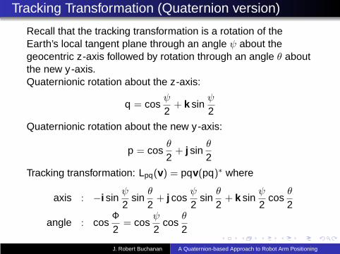
Tracking Transformation (Quaternion version)
Recall that the tracking transformation is a rotation of theEarth’s local tangent plane through an angle ψ about thegeocentric z-axis followed by rotation through an angle θ aboutthe new y -axis.Quaternionic rotation about the z-axis:
q = cosψ
2+ k sin
ψ
2
Quaternionic rotation about the new y -axis:
p = cosθ
2+ j sin
θ
2
Tracking transformation: Lpq(v) = pqv(pq)∗ where
axis : −i sinψ
2sin
θ
2+ j cos
ψ
2sin
θ
2+ k sin
ψ
2cos
θ
2
angle : cosΦ
2= cos
ψ
2cos
θ
2
J. Robert Buchanan A Quaternion-based Approach to Robot Arm Positioning

Quaternion-Based Rotation
Transition from the Body frame to the Earth frame isaccomplished by rotating through an angle Φ about a fixedunit vector u.
Angle Φ and vector u can be embedded in a quaternion q.
q = cosΦ
2+ u sin
Φ
2Note: An equivalent rotation is achieved if u is replaced by −uwhile Φ is replaced by 2π − Φ.
J. Robert Buchanan A Quaternion-based Approach to Robot Arm Positioning

Quaternion-Based Transition Matrix
R =
q20 + q2
1 − q22 − q2
3 2(q1q2 − q0q3) 2(q1q3 + q0q2)
2(q1q2 + q0q3) q20 − q2
1 + q22 − q2
3 2(q2q3 − q0q1)
2(q1q3 − q0q2) 2(q2q3 + q0q1) q20 − q2
1 − q22 + q2
3
We want to calculate q from the input data (GB,HB).
GB = R
00g
and HB = R
HE1
0HE
3
J. Robert Buchanan A Quaternion-based Approach to Robot Arm Positioning

System of Equations
GB1 = 2g(q1q3 − q0q2)
GB2 = 2g(q2q3 + q0q1)
GB3 = g(q2
0 − q21 − q2
2 + q23)
HB1 = HE
1 (q20 + q2
1 − q22 − q2
3) + 2HE3 (q1q3 − q0q2)
HB2 = 2HE
1 (q1q2 − q0q3) + 2HE3 (q2q3 + q0q1)
HB3 = 2HE
1 (q1q3 + q0q2) + HE3 (q2
0 − q21 − q2
2 + q23)
1 = q20 + q2
1 + q22 + q2
3
J. Robert Buchanan A Quaternion-based Approach to Robot Arm Positioning
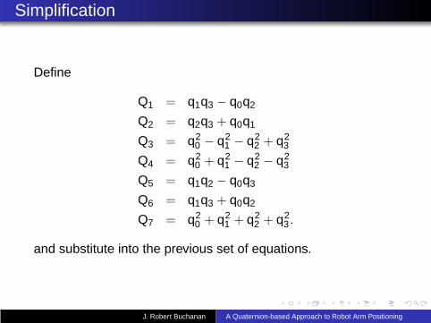
Simplification
Define
Q1 = q1q3 − q0q2
Q2 = q2q3 + q0q1
Q3 = q20 − q2
1 − q22 + q2
3
Q4 = q20 + q2
1 − q22 − q2
3
Q5 = q1q2 − q0q3
Q6 = q1q3 + q0q2
Q7 = q20 + q2
1 + q22 + q2
3 .
and substitute into the previous set of equations.
J. Robert Buchanan A Quaternion-based Approach to Robot Arm Positioning
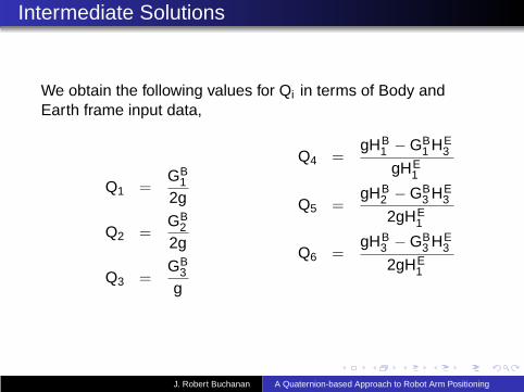
Intermediate Solutions
We obtain the following values for Qi in terms of Body andEarth frame input data,
Q1 =GB
1
2g
Q2 =GB
2
2g
Q3 =GB
3
g
Q4 =gHB
1 − GB1 HE
3
gHE1
Q5 =gHB
2 − GB3 HE
3
2gHE1
Q6 =gHB
3 − GB3 HE
3
2gHE1
J. Robert Buchanan A Quaternion-based Approach to Robot Arm Positioning

Intermediate Set of Equations
We also can derive the following set of equations:
(q20)2 − 1
2(Q3 + Q4)q
20 − 1
4(Q1 − Q6)
2 = 0
(q21)2 +
12(Q3 − Q4)q
21 − 1
4(Q1 + Q6)
2 = 0
(q22)2 +
12(Q3 + Q4)q
22 − 1
4(Q1 − Q6)
2 = 0
(q23)2 − 1
2(Q3 − Q4)q
23 − 1
4(Q1 + Q6)
2 = 0
Choose any single equation and solve for q2i > 0.
J. Robert Buchanan A Quaternion-based Approach to Robot Arm Positioning
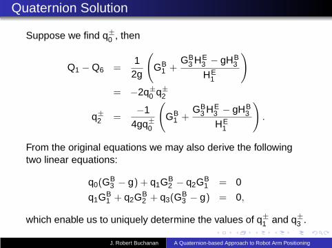
Quaternion Solution
Suppose we find q±
0 , then
Q1 − Q6 =1
2g
(
GB1 +
GB3 HE
3 − gHB3
HE1
)
= −2q±
0 q±
2
q±
2 =−1
4gq±
0
(
GB1 +
GB3 HE
3 − gHB3
HE1
)
.
From the original equations we may also derive the followingtwo linear equations:
q0(GB3 − g) + q1GB
2 − q2GB1 = 0
q1GB1 + q2GB
2 + q3(GB3 − g) = 0,
which enable us to uniquely determine the values of q±
1 and q±
3 .
J. Robert Buchanan A Quaternion-based Approach to Robot Arm Positioning

Constraints
There are also three constraints on the solutions:
(GB1 )2 + (GB
2 )2 + (GB3 )2 = g2
(HB1 )2 + (HB
2 )2 + (HB3 )2 = (HE
1 )2 + (HE3 )2
q20 + q2
1 + q22 + q2
3 = 1
J. Robert Buchanan A Quaternion-based Approach to Robot Arm Positioning
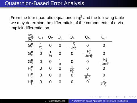
Quaternion-Based Error Analysis
From the four quadratic equations in q2i and the following table
we may determine the differentials of the components of q viaimplicit differentiation.
∂Qj
∂xBi
Q1 Q2 Q3 Q4 Q5 Q6
GB1
12g 0 0 − HE
3gHE
10 0
GB2 0 1
2g 0 0 − HE3
2gHE1
0
GB3 0 0 1
g 0 0 − HE3
2gHE1
HB1 0 0 0 1
HE1
0 0
HB2 0 0 0 0 1
2HE1
0
HB3 0 0 0 0 0 1
2HE1
J. Robert Buchanan A Quaternion-based Approach to Robot Arm Positioning

Matlab Implementation
Matlab routines have been written to convert between thefollowing five types of data:
R
(u,Φ),
Euler angles,
q,
(GB,HB).
Some routines use numerical methods such as Newton’sMethod to calculate outputs, others use the derived formulas.All perform nearly the same.
J. Robert Buchanan A Quaternion-based Approach to Robot Arm Positioning

Quaternion Error Sensitivity
Test:
No error in the Earth frame
Add ǫ noise to (GB,HB)
Calculate (dq0,dq1,dq2,dq3)
J. Robert Buchanan A Quaternion-based Approach to Robot Arm Positioning

Results
0 0.025 0.050 0.075 0.100dGB
0
0.025
0.050
0.075
0.100
dHB
dq0
0 0.025 0.050 0.075 0.100dGB
0
0.025
0.050
0.075
0.100
dHB
dq1
J. Robert Buchanan A Quaternion-based Approach to Robot Arm Positioning

Results (continued)
0 0.025 0.050 0.075 0.100dGB
0
0.025
0.050
0.075
0.100
dHB
dq2
0 0.025 0.050 0.075 0.100dGB
0
0.025
0.050
0.075
0.100
dHB
dq3
J. Robert Buchanan A Quaternion-based Approach to Robot Arm Positioning


![Human Arm Imitation · Human-robot skeleton mapping Robot Joint Angles D-H Parameters [2] Human Arm Robot Arm References [2] [4] Industrial Robots can now be trained and controlled](https://static.fdocuments.us/doc/165x107/5f76b9ded7aa2d6f12317b91/human-arm-imitation-human-robot-skeleton-mapping-robot-joint-angles-d-h-parameters.jpg)