On The Adjacent Channel Interference in Ultra Dense Deployment Master Thesis.pdf

OPEN
ORIGINAL ARTICLE
A III-V-on-Si ultra-dense comb laser
Zhechao Wang1,2,*, Kasper Van Gasse1,2,*, Valentina Moskalenko3, Sylwester Latkowski3, Erwin Bente3,Bart Kuyken1,2 and Gunther Roelkens1,2
Optical frequency combs emerge as a promising technology that enables highly sensitive, near-real-time spectroscopy with a high
resolution. The currently available comb generators are mostly based on bulky and high-cost femtosecond lasers for dense comb
generation (line spacing in the range of 100 MHz to 1 GHz). However, their integrated and low-cost counterparts, which are inte-
grated semiconductor mode-locked lasers, are limited by their large comb spacing, small number of lines and broad optical line-
width. In this study, we report a demonstration of a III-V-on-Si comb laser that can function as a compact, low-cost frequency
comb generator after frequency stabilization. The use of low-loss passive silicon waveguides enables the integration of a long
laser cavity, which enables the laser to be locked in the passive mode at a record-low 1 GHz repetition rate. The 12-nm 10-dB
output optical spectrum and the notably small optical mode spacing results in a dense optical comb that consists of over 1400
equally spaced optical lines. The sub-kHz 10-dB radio frequency linewidth and the narrow longitudinal mode linewidth
(o400 kHz) indicate notably stable mode-locking. Such integrated dense comb lasers are very promising, for example, for high-
resolution and real-time spectroscopy applications.
Light: Science & Applications (2017) 6, e16260; doi:10.1038/lsa.2016.260; published online 19 May 2017
Keywords: mode-locked lasers, near-infrared spectroscopy, optical frequency comb, semiconductor lasers, silicon photonics
INTRODUCTION
Optical frequency combs provide the long sought link between theradio frequency domain and the optical domain. They enable precisemeasurement of optical frequencies by the down-conversion to themeasurable radio frequency (RF) domain. This technology hasrevolutionized the research field of frequency metrology and enabledthe construction of optical clocks1. Recently, frequency combs havealso been proven interesting to the field of spectroscopy2. Using theso-called dual-comb spectroscopic technique3, broadband absorptionspectra can be measured with superior resolution and acquisition timecompared with other techniques such as standard Fourier transformspectroscopy (FTIR). In this technique, one of the combs is used as anarray of local oscillators to down-convert the lines of the probe combto the RF domain. Because the resolution of the technique isinherently determined by the spacing of the lines of the combs, densefrequency comb generators are in high demand. Traditional means ofcomb generation rely on mode-locked fiber lasers4 and mode-lockedtitanium-sapphire lasers5. These bulky and costly lasers combine abroad comb bandwidth with a small line spacing of approximately100 MHz. Reducing the size, cost and power consumption of suchoptical comb generators is of paramount importance to extend theapplication range of optical frequency combs. Therefore, a chip-scale,low-power consumption and low-cost comb source that can beelectrically pumped and generates a broad comb with a small linespacing is desired.
Several approaches can be followed to reach this goal. There hasbeen impressive progress in the field of quantum cascade laserfrequency combs that operate in the mid-infrared and THz wavelengthregions6–9. In addition, the Intensity modulation of a CW laser sourcecan generate frequency-agile combs10, although the frequency span islimited. Thus, a nonlinear spectral broadening step in fiber is mostlyrequired. Recently, many studies focused on the integration of the so-called Kerr combs on a chip, which consist of a dispersion-engineeredmicro-resonator that is optically pumped by a strong continuous wavelaser. The strong power build-up in the cavity enables strong nonlinearinteractions, which generate a comb. Here, the spacing of the comb isdetermined by the free spectral range of the micro-resonator.Encouraging progress has been made in several material systems suchas silicon nitride11, hydex glass12, silicon13,14, and III-V AlGaAsresonators15. However, coupling the pump laser to the high Q-factorresonator can be difficult in real-life scenarios. The high-powerexternal pump laser is also difficult to integrate on a chip, whichmakes the comb generator less compact and rugged. Finally, thetypical large spacing of the comb lines (⩾10 GHz) is not attractive forhigh-resolution dual-comb spectroscopy. Although the comb linespacing can be reduced to below 10 GHz by extending the cavitylength, one would require a much higher pump power to trigger thenonlinear process in the large cavity16.Being the integrated counterpart of the fiber and solid-state mode-
locked lasers (MLLs), monolithically integrated semiconductor MLLs
1Department of Information Technology (INTEC), Photonics Research Group, Ghent University-IMEC, Gent 9052, Belgium; 2Center for Nano- and Biophotonics, Ghent University,Gent 9052, Belgium and 3Electrical Engineering Department, Eindhoven University of Technology, Eindhoven 5600, Netherlands
Correspondence: Z Wang, Email: [email protected]; G Roelkens, Email: [email protected]*These authors contributed equally to this work.
Received 26 July 2016; revised 25 November 2016; accepted 27 November 2016; accepted article preview online 19 May 2017
Light: Science & Applications (2017) 6, e16260; doi:10.1038/lsa.2016.260Official journal of the CIOMP 2047-7538/17www.nature.com/lsa
have seen remarkable progress in the past decade17–24. Mostly drivenby telecom applications, semiconductor MLLs that operate at arepetition rate of 10–100 GHz are widely available. As previouslydiscussed, spectroscopic applications require a smaller comb linespacing in the range of 100 MHz to 1 GHz. Particularly for gasses,the linewidth of an absorption line is in the GHz range. Mainlybecause of the high waveguide loss of III-V waveguides, which limitsthe cavity length, the comb line spacing (determined by the round-triptime in the cavity) of the integrated III-V mode-locked lasers remainsat several GHz. Although this problem can be addressed by usingan external cavity geometry25, the resulting device is not fullyintegrated.In this letter, by leveraging the low optical loss of silicon
waveguides, we present a III-V-on-silicon MLL that passively mode-locks at a record-low repetition rate of 1 GHz. The wide opticalbandwidth (12-nm 10-dB bandwidth) and low repetition rate (1 GHz)result in an optical comb with over 1400 equally spaced narrowlinewidth (o400 kHz) lines.
MATERIALS AND METHODS
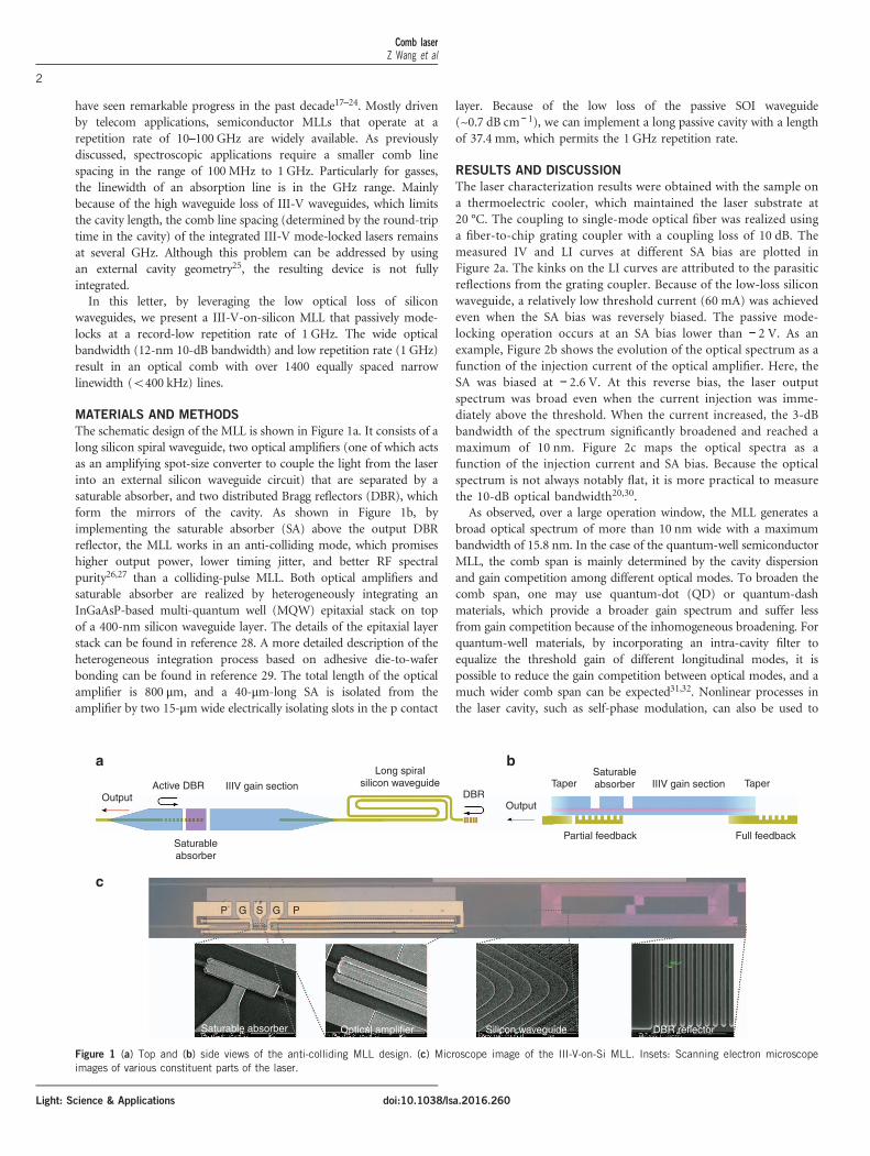
The schematic design of the MLL is shown in Figure 1a. It consists of along silicon spiral waveguide, two optical amplifiers (one of which actsas an amplifying spot-size converter to couple the light from the laserinto an external silicon waveguide circuit) that are separated by asaturable absorber, and two distributed Bragg reflectors (DBR), whichform the mirrors of the cavity. As shown in Figure 1b, byimplementing the saturable absorber (SA) above the output DBRreflector, the MLL works in an anti-colliding mode, which promiseshigher output power, lower timing jitter, and better RF spectralpurity26,27 than a colliding-pulse MLL. Both optical amplifiers andsaturable absorber are realized by heterogeneously integrating anInGaAsP-based multi-quantum well (MQW) epitaxial stack on topof a 400-nm silicon waveguide layer. The details of the epitaxial layerstack can be found in reference 28. A more detailed description of theheterogeneous integration process based on adhesive die-to-waferbonding can be found in reference 29. The total length of the opticalamplifier is 800 μm, and a 40-μm-long SA is isolated from theamplifier by two 15-μm wide electrically isolating slots in the p contact
layer. Because of the low loss of the passive SOI waveguide(~0.7 dB cm− 1), we can implement a long passive cavity with a lengthof 37.4 mm, which permits the 1 GHz repetition rate.
RESULTS AND DISCUSSION
The laser characterization results were obtained with the sample ona thermoelectric cooler, which maintained the laser substrate at20 °C. The coupling to single-mode optical fiber was realized usinga fiber-to-chip grating coupler with a coupling loss of 10 dB. Themeasured IV and LI curves at different SA bias are plotted inFigure 2a. The kinks on the LI curves are attributed to the parasiticreflections from the grating coupler. Because of the low-loss siliconwaveguide, a relatively low threshold current (60 mA) was achievedeven when the SA bias was reversely biased. The passive mode-locking operation occurs at an SA bias lower than − 2 V. As anexample, Figure 2b shows the evolution of the optical spectrum as afunction of the injection current of the optical amplifier. Here, theSA was biased at − 2.6 V. At this reverse bias, the laser outputspectrum was broad even when the current injection was imme-diately above the threshold. When the current increased, the 3-dBbandwidth of the spectrum significantly broadened and reached amaximum of 10 nm. Figure 2c maps the optical spectra as afunction of the injection current and SA bias. Because the opticalspectrum is not always notably flat, it is more practical to measurethe 10-dB optical bandwidth20,30.As observed, over a large operation window, the MLL generates a
broad optical spectrum of more than 10 nm wide with a maximumbandwidth of 15.8 nm. In the case of the quantum-well semiconductorMLL, the comb span is mainly determined by the cavity dispersionand gain competition among different optical modes. To broaden thecomb span, one may use quantum-dot (QD) or quantum-dashmaterials, which provide a broader gain spectrum and suffer lessfrom gain competition because of the inhomogeneous broadening. Forquantum-well materials, by incorporating an intra-cavity filter toequalize the threshold gain of different longitudinal modes, it ispossible to reduce the gain competition between optical modes, and amuch wider comb span can be expected31,32. Nonlinear processes inthe laser cavity, such as self-phase modulation, can also be used to
Output
a b
c
Active DBRDBR
Output
Taper
Partial feedback Full feedback
TaperSaturableabsorber
Saturableabsorber
Saturable absorber Optical amplifier Silicon waveguide DBR reflector
P PG GS
IIIV gain section IIIV gain sectionLong spiral
silicon waveguide
Figure 1 (a) Top and (b) side views of the anti-colliding MLL design. (c) Microscope image of the III-V-on-Si MLL. Insets: Scanning electron microscopeimages of various constituent parts of the laser.
Comb laserZ Wang et al
2
Light: Science & Applications doi:10.1038/lsa.2016.260

extend the bandwidth33. The waveguide dispersion of the current MLLdesign was not compensated (see more details of the dispersioncharacterization below). Further optimization of the cavity dispersioncan further broaden the comb span, which is particularly importantfor spectroscopy applications34,35.In Figure 2c, different operation regions for different harmonic
mode-locking orders are also marked. In a large operation window,the laser is mostly mode-locked at the 2nd harmonic order, that is,with a repetition rate of 2 GHz. The laser can even operate at higherharmonic orders (3rd and 5th) when the injecting current is high andthe reverse bias is relatively low (Figure 2c). When both injectioncurrent and reverse bias are large, the lasing spectra significantly shiftsto shorter wavelengths, and notably strong amplitude modulations(AM) are found to considerably degrade the mode-locking stability.The favored fundamental mode-locking occurs only when the inject-ing current is low and the SA reverse bias is high (see the right-bottomcorner of Figure 2c). Although the laser can be mode-locked at itsfundamental repetition rate when the SA is biased at approximately− 2 V, modulation on top of the RF spectra occurs because of therelaxation oscillation of the laser. Therefore, in the following discus-sion, we will focus on the optimal operation point as indicated by theblack dot in Figure 2c.Figure 3a shows the RF spectrum of the generated pulse train at the
optimal operation point (Icurrent= 91 mA, VSA=− 2.6 V, indicated bythe dot in Figure 2c). The strong fundamental tone that is 55 dB aboveany spurious peaks or noise floor and the clean RF spectrum in the
low-frequency range (see the inset) indicate that there is notably littleresidual amplitude modulation of the pulse train. A more detailed plotof the fundamental tone is shown in Figure 3b. It was recorded with aresolution bandwidth and a video bandwidth of 10 kHz. The exactrepetition rate of the MLL is 1009.259MHz. The 10-dB linewidthmeasured from the spectrum is below 900 Hz. The laser presentssimilar noise properties when it is locked at higher-order harmonics,and the measured RF linewidth is in the range of a few kHz. Asrequired for optical comb spectroscopy, to stabilize the repetition rateof the MLL, one can realize the hybrid mode-locking of the laser bysupplying an extra RF input signal to the SA, which will bediscussed later.Figure 4a shows the optical comb spectrum measured by a high-
resolution optical spectrum analyzer (5 MHz resolution). The MLL isset at the identical optimal operation point as indicated in Figure 2c.A more detailed image of the evenly spaced optical modes is shown inthe inset. The large optical bandwidth (410 nm) and the smallrepetition rate (1 GHz) result in an optical comb with more than 1400optical lines. The small ripples on top of the optical comb areattributed to the fact that the residual reflections from the fiber-to-chip grating coupler and the III-V-to-silicon taper form a Fabry-Perotcavity, which introduces wavelength-dependent transmission. Theorigin of the relatively strong peak on the blue side of the comb isunder investigation, although it can be attributed to the self-phasemodulation process considering the high optical intensity in the highlynonlinear sub-micron silicon waveguides.
–20
–40
a b
0
–20
–40
–60
–80
–100
–120
–140
0 2 4 6 8 10
–60
RF
pow
er (
dBm
per
res
)
RF
pow
er (
dBm
per
res
)
RF
pow
er (
dBm
per
res
)
–80
–40
–60
–80
–100
–120
1009.24 1009.26 1009.280 10 20
Frequency (GHz) Frequency (MHz)
50 kHz
0.9 kHz
Frequency (MHz)
30 40
Figure 3 (a) RF spectrum of the generated pulse train (RBW 300 KHz, VBW 10 KHz) when the laser is operated at the optimal operation point of Figure 2c.Inset: enlarged RF spectrum in the frequency range of 1–10 MHz (b) Detail of the 1-GHz RF tone (RBW 10 Hz, VBW 10 kHz).
0.8
a b c
0.6
0.4
0.0
0.2
1.0
1.5
0.5
Bia
s (V
)
Opt
ical
pow
er (
mW
)
0.00 20 40 60
Current (mA)80 100
90
85
80
75
70
Cur
rent
(m
A)
1580 1590 1600Wavelength (nm)
1610 1620
Power density(dBm per res)
–72–70–68–66–64–62–60–58–56–54
SA bias (V)
110
100
90
80
70–2.0 –2.1 –2.2 –2.3 –2.4 –2.5 –2.6
Cur
rent
(m
A)
3rd
2nd
1st
3rd ML withstrong AM
5th1st
10 dBBW (nm)
357911131517
VSA = –1.5 VVSA = –2.0 VVSA = –2.5 V
Figure 2 (a) Measured Current-Voltage (IV) curve and Light-Current (LI) curves for different SA bias. (b) Measured optical spectra as a function of theinjected current in the gain sections, when the SA is biased at −2.6 V. (c) Mapping of 10-dB optical bandwidth as a function of the SOA injection currentand SA bias. Different harmonic mode-locking regions are marked. The black dot indicates the optimal operation point for the 1-GHz laser operation. AM,amplitude modulation; ML, mode-locking.
Comb laserZ Wang et al
3
Light: Science & Applicationsdoi:10.1038/lsa.2016.260

The linewidth of the longitudinal modes of the laser was firstmeasured by heterodyning the output of the MLL with a CW OPO(Argus 2400 sf, 50 kHz linewidth) on a 26-GHz bandwidth photo-diode with TIA and analyzing the output with an electrical spectrumanalyzer (Keysight EXA N9010). The temperature of the TEC slowlyfluctuated as follows: a temperature change of 0.1 degree Celsiuscorresponded to an optical frequency shift of 1.5 GHz at 1600 nm.Thus, the generated heterodyne beat note slowly drifted, whichsubstantially broadened the measured linewidth as shown inFigure 4b. The signal-to-noise ratio is poor mainly because of thelow-resolution and fast-scan-speed setting of the spectrum analyzer tocapture an instantaneous image of the drifting beat note. To cancel theeffect of such temperature fluctuation, a delayed self-heterodynemethod was used. A narrow spectral band of the MLL output(0.5 nm wide optical spectrum centered at 1600 nm) was split intotwo arms. In one arm, the optical signal went through a 5-km-longsingle-mode fiber, whereas a 200-MHz frequency shift was introducedin the other arm. The beat note measured by mixing the two opticalsignals is plotted in Figure 4c. A fairly narrow beat note with below-500-kHz 3-dB bandwidth was obtained, which indicates an opticallinewidth below 250 kHz. Note that it is not possible to filter out asingle longitudinal mode for the linewidth measurement. Therefore,the current beat note was obtained by beating ~ 60 optical modes (in a0.5-nm bandwidth). Therefore, the intrinsic optical linewidth of eachlongitudinal mode may be even smaller. The identical measurementwas performed by scanning the central wavelength of the filter from1598 to 1608 nm, and an optical linewidth below 400 kHz wasobtained across the entire wavelength range. The optical linewidth
could be further reduced by implementing an optical phase-lockedloop to lock the MLL to an external narrow linewidth laser, whichcould be potentially co-integrated with the MLL36.From the measured auto-correlation (AC) trace of the pulse train
(Figure 5a, the laser operates at the identical optimal point ofFigure 2c), the fitted pulse width was ~ 7 ps, which indicates thatthe generated pulse was not transform limited. Similar to thetechnique in reference 37, using a tunable filter and an EDFA, weamplified and fed different slices of the optical comb (with a 1-nmbandwidth) into a high-speed photodiode and recorded the real-timepulse traces using a 160-Giga samples per second real-time oscillo-scope. A typical time trace of the pulse train is shown in the inset ofFigure 5b. An overall chirp of − 2.5 ps nm− 1 was derived, which alsoincluded the chirp introduced by the EDFA (−1 ps nm− 1, which wasmeasured by using a standard time-of-flight dispersion measurement).The chirp management of the laser cavity design or an externaldispersion-compensating optical fiber can further reduce the pulsewidth, but it is not an important characteristic of an optical comb forspectroscopy. To fully describe the pulse width evolution, we plottedthe AC trace width as a function of the injection current and SA biasin Figure 5c. The AC trace width was maintained below 15 ps over alarge operation window, whereas the pulse width was considerablybroader (460 ps) for the operation region at the top-left corner of thefigure, which corresponds to the small optical bandwidths inFigure 2c.Two degrees of freedoms, that is, the repetition rate and the offset
frequency, of the presented mode-locked laser must be stabilized torealize a frequency comb. The hybrid mode-locking of the laser was
–55
a
b c
–60
–50
–60
–70
1602.00 1602.05 1602.10 1602.15 1602.20
–65
–70
–75
0
–5
–10
–15
–20
–25
RF
pow
er (
dBm
per
res
)
RF
pow
er (
mW
)–30
–35
–30
–45–10 –5 5 100
1593 1596 1599 1602
Wavelength (nm)
0.7 MHz
496 kHz1E-8
1E-9
1E-10
190 200 210
Frequency (MHz) Frequency (MHz)
Wavelength (nm)
1605 1608
Pow
er d
ensi
ty (
dBm
per
res
)
Pow
er d
ensi
ty (
dBm
per
res
)
Figure 4 (a) An optical comb generated by the passively locked 1 GHz MLL. Inset: a detail of evenly spaced optical modes in the comb. (b) Beat notebetween the optical comb and the tunable laser at a wavelength of 1600 nm. (c) Measured optical linewidth of the MLL using the delayed self-heterodynemethod, which indicates an optical linewidth below 250 kHz. The black dots are the measured data, and the red curve is the corresponding Lorentzianfitting.
Comb laserZ Wang et al
4
Light: Science & Applications doi:10.1038/lsa.2016.260

performed by supplying an RF signal to the SA to stabilize therepetition rate. The corresponding optical comb is shown inFigure 6a. The MLL operation conditions were 91 mA currentinjection, − 2.6 V SA bias, 1.00930116 GHz RF input frequency and8 dBm RF input power. Compared with the optical comb generated bythe passive mode-locking (Figure 4a), the peak at the blue side of thespectrum was less pronounced when the MLL was hybrid mode-locked(Figure 6a). More importantly, the optical comb slightly extended tothe red side instead of collapsing into a much narrower comb when thelaser was hybrid mode-locked19. An analysis of the pulse train in the RFdomain (Figure 6b) reveals that the FWHM of the fundamental RFtone was sub-Hz, which proves that the line spacing of the optical
comb can indeed be well stabilized (see the RF peak in Figure 6c). TheAC trace of the output pulse is shown in Figure 6d, which shows aslightly broadened pulse width compared with the passive mode-locking case. In addition, the measured linewidth of the individualcomb lines was again less than 1MHz across the entire comb(Figure 6e), which is comparable to the measured linewidths whenthe laser was passively mode-locked (Figure 4). The measurementresults prove that it is indeed possible to stabilize an optical combwithout reducing the overall optical bandwidth, which is notablypromising for high-resolution, high-speed spectroscopic applications.In addition to the repetition rate, the other degree of freedom of the
laser, which is the offset frequency fceo24, must be stabilized. The
1000a b c
0.02
0.01
Am
plitu
de (
V)
0.000 1
Time (ns)
–2.5 ps/nm
2
0.31 nm@1604 nm 110
MLL withstrong AM
101418222630
AC tracewidth (ps)
>60 ps
100
90
80
70–2.0 –2.1 –2.2 –2.3
Absorber bias (V)
–2.4 –2.5 –2.6
1 nm@1603 nm
1 nm@1602 nm
1 nm@1601 nm
1 nm@1600 nm
1 nm@1599 nm
1 nm@1598 nm
1 nm@1597 nm
1 nm@1596 nm
0.2
0.1
0.0–300 –200 –100 1000
800
600
400
200
Aut
ocor
rela
tion
inte
nsity
(a.
u.)
Rel
ativ
e in
tens
ity (
a.u.
)
Cur
rent
(m
A)
0–75 –50 –25 250 50 75
Time (ps) Relative time delay (ps)
Figure 5 (a) An auto-correlation trace and the corresponding fit of the MLL output. (b) The recorded pulse traces by a real-time oscilloscope for differentparts of the optical comb. The inset shows a time trace of the pulse trains, which were recorded using a real-time oscilloscope. (c) Mapping of the auto-correlation trace width over the current injection and SA bias. The arrow indicates the optimal operation point.
–45
–50
–20
–40
–60
–80
0 10 20 30 40
–55
–60
–65
–70
–75
–50
–55
–60
–65
–70
–75
–201000 0
–10
–20
–30
–40
–50
800
600
400
200
0–75 –50
Time delay (ps)
–25 –10 0 5 10–525 50 750
–40
–60
–80
–100
–120
–140
–1601009296 1009299 1009302 1009305
1595 1600
Wavelength (nm)
1605 1610
Pow
er d
ensi
ty (
dBm
per
res
)
Pow
er d
ensi
ty (
dBm
per
res
)
Wavelength (nm) RF
pow
er (
dBm
per
res
)
RF
pow
er (
dBm
per
res
)
RF
pow
er d
Bm
per
res
)
Aut
ocor
rela
tion
inte
nsity
(a.
u.)
Frequency (GHz)
0.75 MHz
Frequency (kHz) Frequency (MHz)
a
c d e
b
1601.0 1601.1 1601.2 1601.3
Figure 6 (a) High-resolution optical spectrum of the optical comb when the MLL is hybrid mode-locked (inset: magnification of the optical spectrum). (b) RFspectrum of the generated pulse train. (c) Fundamental RF peak over a span of 10 kHz. (d) An auto-correlation trace of the output pulse when the laser ishybrid mode-locked. (e) Beat note between the optical comb and the tunable laser at a wavelength of 1607 nm, which indicates that the linewidth of theoptical mode is smaller than 1 MHz.
Comb laserZ Wang et al
5
Light: Science & Applicationsdoi:10.1038/lsa.2016.260
widely explored self-referencing-based stabilization approach is notfeasible here because of the lack of an octave-spanning spectrumwithout further nonlinear spectral broadening14,38. Furthermore, fceocan also be stabilized by the electronic feedback modulation of theinjected current in the laser using an external reference39 or byexternal laser injection40, as we recently demonstrated. The electronicfeedback scheme is more elegant because it is more robust than opticalinjection locking and does not require optical isolation. Our hetero-dyne measurements (beating the MLL output with the narrowlinewidth emission from a CW OPO) show that the fine tuning ofthe laser injection current modifies the offset frequency. The next stepof the work is the implementation of an integrated electronic feedbackloop to control fceo by modulating the injection current.It is worth noting that in some cases, it is not critical to stabilize the
absolute offset frequencies of the two combs for dual-comb spectro-scopy. Using an external reference, one can track the drift of the twofrequency combs and implement signal processing to compensate forthe instabilities of free-running lasers41.The performance of the presented mode-locked laser is compared
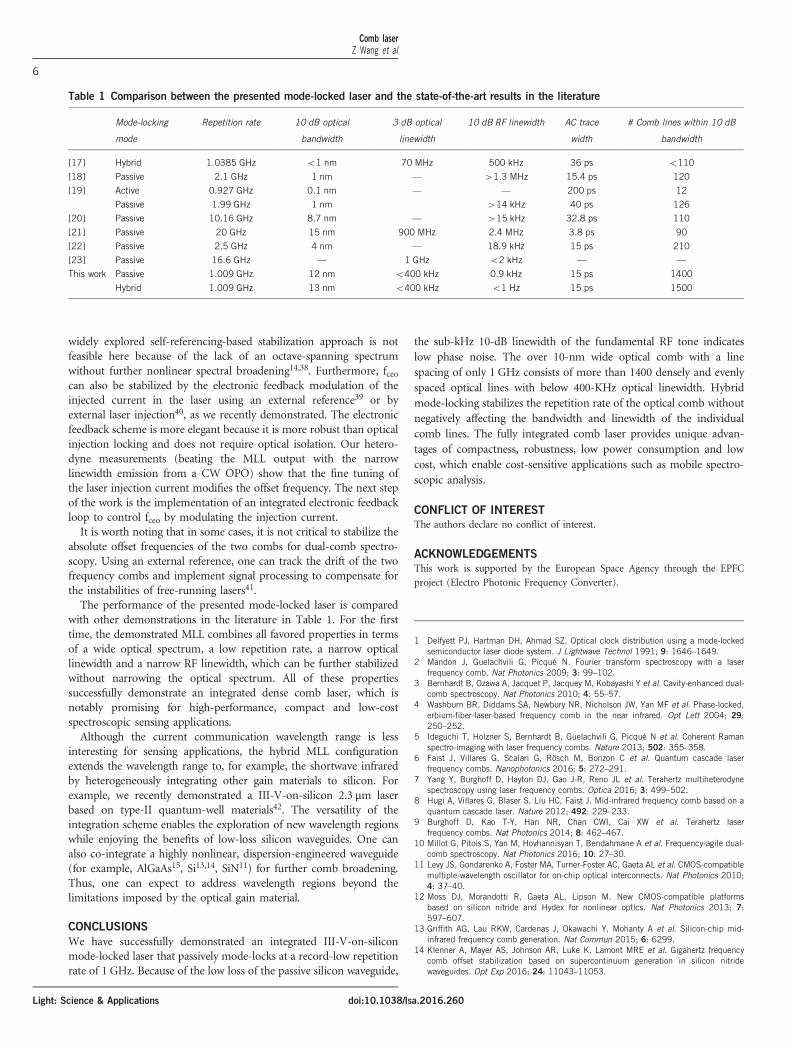
with other demonstrations in the literature in Table 1. For the firsttime, the demonstrated MLL combines all favored properties in termsof a wide optical spectrum, a low repetition rate, a narrow opticallinewidth and a narrow RF linewidth, which can be further stabilizedwithout narrowing the optical spectrum. All of these propertiessuccessfully demonstrate an integrated dense comb laser, which isnotably promising for high-performance, compact and low-costspectroscopic sensing applications.Although the current communication wavelength range is less
interesting for sensing applications, the hybrid MLL configurationextends the wavelength range to, for example, the shortwave infraredby heterogeneously integrating other gain materials to silicon. Forexample, we recently demonstrated a III-V-on-silicon 2.3 μm laserbased on type-II quantum-well materials42. The versatility of theintegration scheme enables the exploration of new wavelength regionswhile enjoying the benefits of low-loss silicon waveguides. One canalso co-integrate a highly nonlinear, dispersion-engineered waveguide(for example, AlGaAs15, Si13,14, SiN11) for further comb broadening.Thus, one can expect to address wavelength regions beyond thelimitations imposed by the optical gain material.
CONCLUSIONS
We have successfully demonstrated an integrated III-V-on-siliconmode-locked laser that passively mode-locks at a record-low repetitionrate of 1 GHz. Because of the low loss of the passive silicon waveguide,
the sub-kHz 10-dB linewidth of the fundamental RF tone indicateslow phase noise. The over 10-nm wide optical comb with a linespacing of only 1 GHz consists of more than 1400 densely and evenlyspaced optical lines with below 400-KHz optical linewidth. Hybridmode-locking stabilizes the repetition rate of the optical comb withoutnegatively affecting the bandwidth and linewidth of the individualcomb lines. The fully integrated comb laser provides unique advan-tages of compactness, robustness, low power consumption and lowcost, which enable cost-sensitive applications such as mobile spectro-scopic analysis.
CONFLICT OF INTEREST
The authors declare no conflict of interest.
ACKNOWLEDGEMENTS
This work is supported by the European Space Agency through the EPFC
project (Electro Photonic Frequency Converter).
1 Delfyett PJ, Hartman DH, Ahmad SZ. Optical clock distribution using a mode-lockedsemiconductor laser diode system. J Lightwave Technol 1991; 9: 1646–1649.
2 Mandon J, Guelachvili G, Picqué N. Fourier transform spectroscopy with a laserfrequency comb. Nat Photonics 2009; 3: 99–102.
3 Bernhardt B, Ozawa A, Jacquet P, Jacquey M, Kobayashi Y et al. Cavity-enhanced dual-comb spectroscopy. Nat Photonics 2010; 4: 55–57.
4 Washburn BR, Diddams SA, Newbury NR, Nicholson JW, Yan MF et al. Phase-locked,erbium-fiber-laser-based frequency comb in the near infrared. Opt Lett 2004; 29:250–252.
5 Ideguchi T, Holzner S, Bernhardt B, Guelachvili G, Picqué N et al. Coherent Ramanspectro-imaging with laser frequency combs. Nature 2013; 502: 355–358.
6 Faist J, Villares G, Scalari G, Rösch M, Bonzon C et al. Quantum cascade laserfrequency combs. Nanophotonics 2016; 5: 272–291.
7 Yang Y, Burghoff D, Hayton DJ, Gao J-R, Reno JL et al. Terahertz multiheterodynespectroscopy using laser frequency combs. Optica 2016; 3: 499–502.
8 Hugi A, Villares G, Blaser S, Liu HC, Faist J. Mid-infrared frequency comb based on aquantum cascade laser. Nature 2012; 492: 229–233.
9 Burghoff D, Kao T-Y, Han NR, Chan CWI, Cai XW et al. Terahertz laserfrequency combs. Nat Photonics 2014; 8: 462–467.
10 Millot G, Pitois S, Yan M, Hovhannisyan T, Bendahmane A et al. Frequency-agile dual-comb spectroscopy. Nat Photonics 2016; 10: 27–30.
11 Levy JS, Gondarenko A, Foster MA, Turner-Foster AC, Gaeta AL et al. CMOS-compatiblemultiple-wavelength oscillator for on-chip optical interconnects. Nat Photonics 2010;4: 37–40.
12 Moss DJ, Morandotti R, Gaeta AL, Lipson M. New CMOS-compatible platformsbased on silicon nitride and Hydex for nonlinear optics. Nat Photonics 2013; 7:597–607.
13 Griffith AG, Lau RKW, Cardenas J, Okawachi Y, Mohanty A et al. Silicon-chip mid-infrared frequency comb generation. Nat Commun 2015; 6: 6299.
14 Klenner A, Mayer AS, Johnson AR, Luke K, Lamont MRE et al. Gigahertz frequencycomb offset stabilization based on supercontinuum generation in silicon nitridewaveguides. Opt Exp 2016; 24: 11043–11053.
Table 1 Comparison between the presented mode-locked laser and the state-of-the-art results in the literature
Mode-locking
mode
Repetition rate 10 dB optical
bandwidth
3 dB optical
linewidth
10 dB RF linewidth AC trace
width
# Comb lines within 10 dB
bandwidth
[17] Hybrid 1.0385 GHz o1 nm 70 MHz 500 kHz 36 ps o110
[18] Passive 2.1 GHz 1 nm — 41.3 MHz 15.4 ps 120
[19] Active 0.927 GHz 0.1 nm — — 200 ps 12
Passive 1.99 GHz 1 nm 414 kHz 40 ps 126
[20] Passive 10.16 GHz 8.7 nm — 415 kHz 32.8 ps 110
[21] Passive 20 GHz 15 nm 900 MHz 2.4 MHz 3.8 ps 90
[22] Passive 2.5 GHz 4 nm — 18.9 kHz 15 ps 210
[23] Passive 16.6 GHz — 1 GHz o2 kHz — —
This work Passive 1.009 GHz 12 nm o400 kHz 0.9 kHz 15 ps 1400
Hybrid 1.009 GHz 13 nm o400 kHz o1 Hz 15 ps 1500
Comb laserZ Wang et al
6
Light: Science & Applications doi:10.1038/lsa.2016.260

15 Pu MH, Ottaviano L, Semenova E, Yvind K. A highly efficient nonlinear platform:AlGaAs-On-Insulator. 2015 European Conference on Lasers and Electro-Optics—European Quantum Electronics Conference, 21-25 June 2015; Munich, GermanyOptical Society of America: Munich, Germany; 2015.
16 Li J, Lee H, Chen T, Vahala KJ. Low-Pump-Power, Low-Phase-Noise, and microwave tomillimeter-wave repetition rate operation in Microcombs. Phys Rev Lett 2012; 109:233901.
17 Cheung S, Baek JH, Scott RP, Fontaine NK, Soares FM et al. 1-GHz MonolithicallyIntegrated Hybrid Mode-Locked InP Laser. IEEE Photonics Technol Lett 2010; 22:1793–1795.
18 Li Y, Breivik M, Feng CY, Fimland BO, Lester LF. A low repetition rate all-activemonolithic passively mode-locked quantum-dot laser. IEEE Photonics Technol Lett2011; 23: 1019–1021.
19 Srinivasan S, Davenport M, Heck MJR, Hutchinson J, Norberg E et al. Low phase noisehybrid silicon mode-locked lasers. Front Optoelectron 2014; 7: 265–276.
20 Corral V, Guzmán R, Gordón C, Leijtens XJM, Carpintero G. Optical frequency combgenerator based on a monolithically integrated passive mode-locked ring laser with aMach-Zehnder interferometer. Opt Lett 2016; 41: 1937–1940.
21 Moskalenko V, Latkowski S, Tahvili S, de Vries T, Smit M et al. Record bandwidth andsub-picosecond pulses from a monolithically integrated mode-locked quantum wellring laser. Opt Exp 2014; 22: 28865–28874.
22 Latkowski S, Moskalenko V, Tahvili S, Augustin L, Smit M et al. Monolithicallyintegrated 2.5 GHz extended cavity mode-locked ring laser with intracavity phasemodulators. Opt Lett 2015; 40: 77–80.
23 Kefelian F, O'Donoghue SO, Todaro MT, McInerney JG, Huyet G. RF Linewidth inMonolithic Passively Mode-Locked Semiconductor Laser. IEEE Photonics Technol Lett2008; 20: 1405–1407.
24 Tilma BW, Mangold M, Zaugg CA, Link SM, Waldburger D et al. Recent advances inultrafast semiconductor disk lasers. Light Sci Appl 2015; 4: 310.
25 Aschwanden A, Lorenser D, Unold HJ, Paschotta R, Gini E et al. 2.1-W picosecondpassively mode-locked external-cavity semiconductor laser. Opt Lett 2005; 30:272–274.
26 Javaloyes J, Balle S. Anticolliding design for monolithic passively mode-lockedsemiconductor lasers. Opt Lett 2011; 36: 4407–4409.
27 Moskalenko V, Williams KA, Bente EAJM. Integrated Extended-Cavity 1.5-μm semi-conductor laser switchable between self- and anti-colliding pulse passive mode-lockingconfiguration. IEEE J Sel Top Quant Electron 2015; 21: 40–45.
28 Keyvaninia S, Uvin S, Tassaert M, Wang Z, Fu X et al. III-V-on-silicon anti-collidingpulse-type mode-locked laser. Opt Lett 2015; 40: 3057–3060.
29 Roelkens G, Abassi A, Cardile P, Dave U, de Groote A et al. III-V-on-siliconphotonic devices for optical communication and sensing. Photonics 2015; 2:969–1004.
30 Parker JS, Guzzon RS, Norberg EJ, Bhardwaj A, Binetti PRA et al. Theory and design ofTHz intracavity gain-flattened filters for monolithically integrated mode-locked lasers.IEEE J Quant Electron 2012; 48: 114–122.
31 Parker JS, Bhardwaj A, Binetti PRA, Hung YJ, Coldren LA. Monolithically Integratedgain-flattened ring mode-locked laser for comb-line generation. IEEE Photonics TechnolLett 2012; 24: 131–133.
32 Mielke MM, Alphonse GA, Delfyett PJ. Multiwavelength modelocked semiconductorlasers for photonic access network applications. IEEE J Sel Area Commun 2007; 25:120–128.
33 Moskalenko V, Williams K, Koelemeij J, Bente E. 42 nm wide coherent frequency combgenerated by a QW based integrated passively mode-locked laser. Proceedings of the25th International Semiconductor Laser Conference (ISLC 2016); 14 September 2016;Kobe, Japan ISLC: Kobe, Japan; 2016.
34 Sato K, Hirano A, Ishii H. Chirp-compensated 40-GHz mode-locked lasers integratedwith electroabsorption modulators and chirped gratings. IEEE J Sel Top Quant Electron1999; 5: 590–595.
35 Strain MJ, Stolarz PM, Sorel M. Passively mode-locked lasers with integrated chirpedbragg grating reflectors. IEEE J Quant Electron 2011; 47: 492–499.
36 Lu MZ, Park H, Bloch E, Sivananthan A, Bhardwaj A et al. Highly integrated opticalheterodyne phase-locked loop with phase/frequency detection. Opt Exp 2012; 20:9736–9741.
37 Tahvili MS, Du L, Heck MJR, Nötzel R, Smit MK et al. Dual-wavelength passive andhybrid mode-locking of 3, 4.5 and 10 GHz InAs/InP(100) quantum dot lasers. Opt Exp2012; 20: 8117–8135.
38 Brochard P, Jornod N, Schilt S, Wittwer VJ, Hakobyan S et al. First investigation of thenoise and modulation properties of the carrier-envelope offset in a modelockedsemiconductor laser. Opt Lett 2016; 41: 3165–3168.
39 Apolonski A, Poppe A, Tempea G, Spielmann C, Udem T et al. Controlling the phaseevolution of few-cycle light pulses. Phys Rev Lett 2000; 85: 740–743.
40 Uvin S, Keyvaninia S, Lelarge F, Duan G-H, Kuyken B et al. Narrow line width frequencycomb source based on an injection-locked III-V-on-silicon mode-locked laser. Opt Exp2016; 24: 5277–5286.
41 Ideguchi T, Poisson A, Guelachvili G, Picqué N, Hänsch TW. Adaptive real-time dual-comb spectroscopy. Nat Commun 2014; 5: 3375.
42 Wang RJ, Sprengel S, Boehm G, Muneeb M, Baets R et al. 2.3 μm range InP-basedtype-II quantum well Fabry-Perot lasers heterogeneously integrated on a silicon photonicintegrated circuit. Opt Exp 2016; 24: 21081–21089.
This work is licensed under a Creative Commons Attribution 4.0International License. The images or other third party material in this
article are included in the article’s Creative Commons license, unless indicated otherwisein the credit line; if thematerial is not includedunder theCreativeCommons license, userswill need toobtainpermission fromthe licenseholder to reproduce thematerial.Toviewacopy of this license, visit http://creativecommons.org/licenses/by/4.0/
r The Author(s) 2017
Comb laserZ Wang et al
7
Light: Science & Applicationsdoi:10.1038/lsa.2016.260