A 1 T. Mead
29
1 ,- i < CONSUWERS POWER C0WPANY ! PAUSADES NUCLEAR PLANT 1 REACTOR VESSEL EXAMINATION PROGRAW PLAN INTERVAL 2. PERIOD 3 AND INTERVAL 3 PERIOD 1 ) l REVISION 2 JUNE 18,1995 I . [ Prepared by: "' ' D. Kurek Wetallurgical and NDE Analysis Westinghouse Nuclear Technology Division A 1 T. Mead 6-tE-9s Approved by: " J. Munson Wes Dyne International For the Utility; dM k d>AI I ' ' T. Fouty / Consumers Power Company Palisades Nuclear Plant | | i 9602270197 960219 PDR ADOCK 05000255 $ PDR
Transcript of A 1 T. Mead

1
,-
i
<
CONSUWERS POWER C0WPANY!
PAUSADES NUCLEAR PLANT1
REACTOR VESSEL EXAMINATION PROGRAW PLAN
INTERVAL 2. PERIOD 3 AND INTERVAL 3 PERIOD 1 )
l.
REVISION 2
JUNE 18,1995 I
.
[Prepared by: "' 'D. KurekWetallurgical and NDE AnalysisWestinghouse Nuclear Technology Division
A 1 T. Mead 6-tE-9sApproved by: "J. MunsonWes Dyne International
For the Utility; dM k d>AI I' '
T. Fouty /
Consumers Power Company
Palisades Nuclear Plant
|
|
i
9602270197 960219PDR ADOCK 05000255$ PDR

. _ -. - . _ _ _ - _ _ _ _ _ . ._
Consumers Power Company
Palisades Nuclear Plant.
Reactor Vessel Examination Program Plan
Interval 2. Period 3 and Interval 3. Period 1
Examination
items and areas listed on the attached tables are to be examined as indicated,in accordance with the
Palisades Plant Outage Plan, based on the 1983 Edition of the ASME Code Section XI. Summer 1983
Addenda for Interval 2. Period 3 examinations, and the 1989 Edition of Section XI for !nterval 3.
Period i examinations. In addition. the WesDyne International position on USNRC Regulatory
Guide 1.150 Revision I will be utilized.
All examinations will be conducted to the maximum extent practical with the access provided and
within the limitation of component geometry.
Vessel Tool Interface Parameters
1. Tool zero leg will be aligned at vessel 90 for weld examination.
2. Closure head guide studs are located at stud hold positions i 1 and 28. Stud holes arecentered on a 192.12" bolt circle diameter, numbered clockwise starting with #1 stud hole
centered at 0.I
3. Al dimensions referenced from the flange bolt surface at the top of the vessel and from 0-
vessel axis.4
Examination Reauirements
- Procedure CPAL-ISI-254 shall be used for remote reactor vessel examinations.
- Procedure PAL-ISI-54 shall be used for manual exeminations of the reactor vessel upper
shell to flange weld.
- Procedure PAL-ISI-55 shall be used for manual examinations of threads in flange.
' - Procedure WDI-DP-01 shall be used for Dynapulser linearity verification.
- Procedure WDI-INST-10 shall be used for manual UT equipment calibration and qualification. ,
,
- . . .. . ._ . ..
h
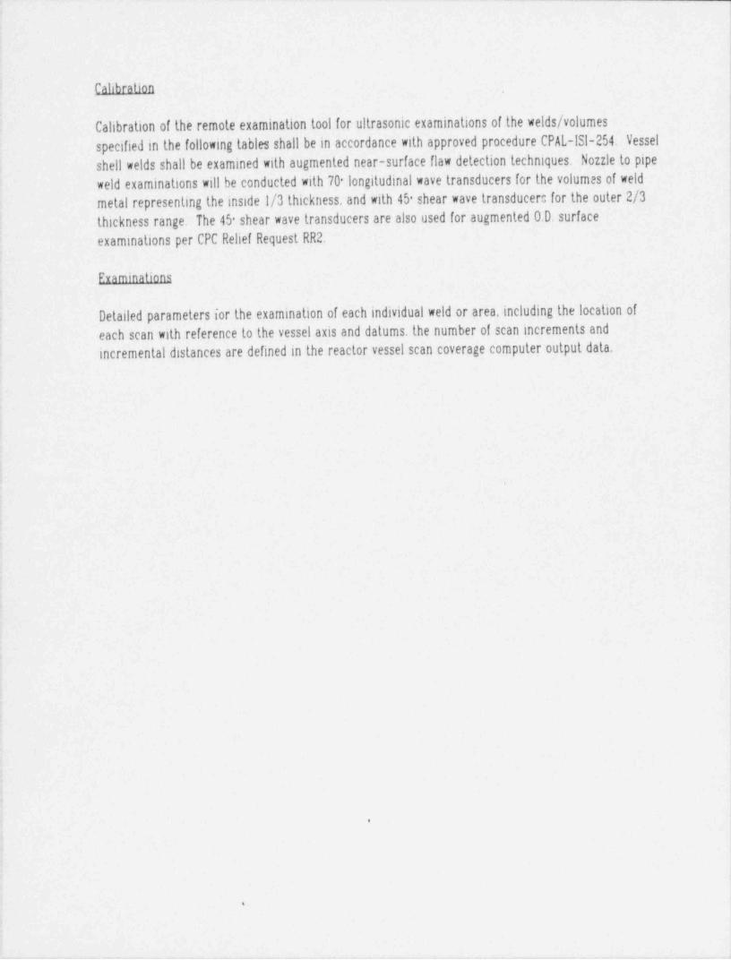
' Calibration
Calibration of the remote examination tool for ultrasonic examinations of the welds / volumesspecified in the following tables shall be in accordance with approved procedure CPAL-ISI-254. Vessel-shell welds shall be examined with augmented near-surface flaw detection techniques. Nozzle to pipe
weld examinations will be conducted with 70 longitudinal wave transducers for the volumes of weld'
metal representing the inside 1/3 thickness, and with 45 shear wave transducer: for the outer 2/3
thickness range. The 45 shear wave transducers are also used for augmented 0.D. surface
examinations per CPC Relief Request RR2.
2
Framinations
Detailed parameters for the examination of each individual weld or area, including the location of:
i each scan with reference to the vessel axis and datums. the number of scan increments andincremental distances are defined in the reactor vessel scan coverage computer output data.
; I
|
4 <
d
!ei
f1
4
3
d
.
$
4
,
3
j
.
t
4

. _ _ _ _ _ _ _ _ _ _ __ _ _ _ _ _ _ _ _ _ _ _ _ _ _ _ _ _ _ _ _ _ _ _ _ _ _ _ _ _ _ _ _ _
PAllSADES
TABLEIINTERVAL 2 PERIOD 3
-
EXAl8MAfl0N/CAIJBRAfl0N REQUIREMENTS
Code Code item / Area Search Refract Cahbration Block
Cat. Item Pkg.| Description Veld No. Unit Angle No Reflectors Surf
B-A Bl.30 I Vessel to flange (ID. Automated) 7-112 S-1 701 43-PAL C.H.K A.
S-2 70 1 43-PAL C.ll.K A
Bl.12 Upper Shell long at 90- 1-112A S-3 45 S 43-PAL D.E.F A
S-4 45-S 43-PAL D.E.F A
Bl.12 Upg,er Shelllong at 210- I-1128 S-5 0L 43-PAL A.B.C A
S-6 60 S 43-PAL D.E.F A
Bl.12 Upper Shell long at 330- 1-il2C S-7 45 L 43-PAL C.ll. Note 1 A
S-8 60-S 43-PAL D.E.F A
B-A Bl.11 2 Upper to Interim Shell Cire. 8-112 S-1 70-L 43-PAL C.II.K A
S-2 70 L 43-PAL C.ll K A
Bl.1 Interim to lower Shell Cire. 9-112 S-3 45 S 44-PAL D.EJ A
S-4 45 S 44-PAL D.E.F A
Bl.12 laterim Shell long at 270- 2-Il2A S-5 0- L 44-PAL A.B.C A
S-6 60 S 44-PAL D.E.F A
Bl.12 Interim Shell long at 30- 2-1128 S-7 451 43-PAL C.ll. Note I A
S-8 60 S 44-PAL D.E.F A
Bl.12 Interim Shelllong at 150- 2-112C
Bl.12 lower Shell long at 90- 3-Il2A,
Bl.12 tower Shelllong at 210- 3-1128
Bl.12 lower Shell long at 330- 3-112C.
Note i Sizing transducer.
Core region base metal examinations. where inan ated, shall be performed with calibration package 12.Ceneral Note
_ _ _ _ . _ _ _ - - __ _ . _ _ _ _ - _ _ _ _ _ _ - - .
________ ____
PAljSADES
TABlf IINTERVAL 2 PERIOD 3
EXAMINATION /CAljBRATION REQUIREMENTS
Code Code item / Area Search Refract. Calibration Block
Cat. Item Pkg.I Description Veld No. Unit Angle No Reflectors Surf
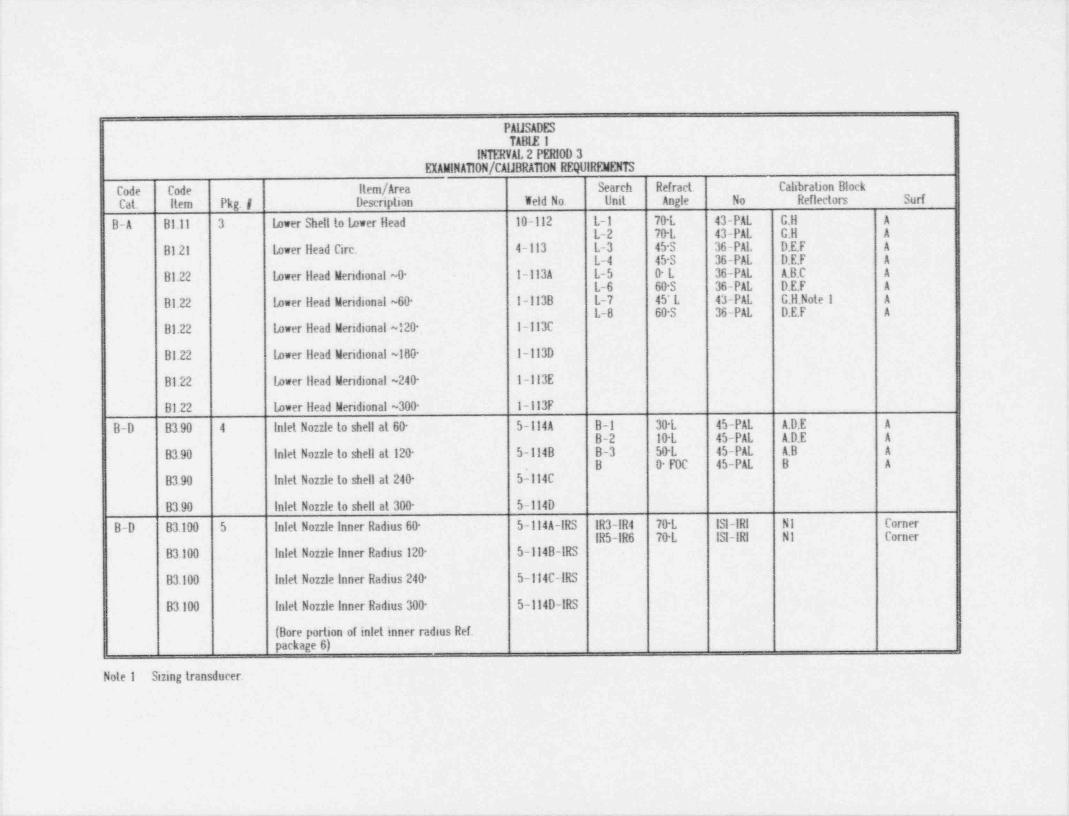
B-A Bl.ll 3 lower Shell to Lower Head 10-112 L-1 70 L 43-PAL C.H A
L-2 70 L 43-PAL C.H A
Bl.21 lower llead Cire. 4-113 L-3 45 S 36-PAL D.E.F A
L-4 45 S 36-PAL D.E.F A
Bl.22 lower llead Meridional ~0- 1-Il3A L-5 0L 36-PAL A.B.C A
L-6 60 S 36-PAL D.E.F A
Bl.22 lower Head Meridional ~60- 1-113B L-7 45 L 43-PAL C.H. Note 1 A
L-6 60-S 36-PAL DI.F A
Bl.22 tower Head Meridional ~120- 1-113C
Bl.22 lower llead Meridional ~180- 1-il3D
Bl.22 lower llead Meridional ~240- 1-113E
Bl.22 lower Head Meridional ~300- 1-ll3F
B-D B3.90 4 Inlet Nozzle to shell at 60- 5-il4A B-1 30 L 45-PAL A.D.E A
B-2 10 L 45-PAL A.D.E A
B3.90 Inlet Nozzle to shell at 120- 5-114B B-3 50-L 45-PAL A.B A '
. B 0 F0C 45-PAL B A
B3.90 Inlet Nozzle to shell at 240- 5-114C
B3.90 Inlet Nozzle to shell at 300- 5-114D
B-D B3.100 5 Inlet Nozzle Inner Radius 60- 5-Il4A-IRS IR3-IR4 70 L ISI-IRI Ni CornerIR5-IR6 70 L ISI-IRI N1 Corner
B3.100 Inlet Nozzle Inner Radius 120- 5-il48-IRS
B3.100 Inlet Nozzle inner Radius 240- 5-ll4C-IRS
B3.100 Inlet Nozzle Inner Radius 300- 5-ll4D-IRS
(Bore portion of inlet inner radius Ref.package 6)
Note 1 Sizing transducer.
_ _ _ _ _ _ _ _ _ _ _ _ _ _ _ _ _ . _ _ _ _ _ _ _ _ - _ _ - _ _ _ _ _ _ . - . _ - _ _ _ - _ _ - _ _ - _ _ _ - _

_ _ _ _ _ _ _ _ _ _ _ _ _ _ _ _ _ _ _ _ _ -___ _ _ - _ _ _ _ _ _ _ _ _ _ _ _ _ _ _ _ _ _ _ . __ ________ _ _ _ _ . . _ _ _ _ _ _ . _ _ _ _ _ - _ - _ _ _ _ _ _ _ _ _ _ _ _ _ _ _ _ _ _ _ _ _-_________________ - ___ _ - --
,
1
PAIJSADESTABLE 1
INTERVAL 2 PERIOD 3EIAMINAfl0N/CAIJBRAfl0N REQUIREMENTS
Code Code item / Area Search Refract Cahbration Block
Cal item Pkg.I Description Veld No. Unit Angle No Reflectors Surf
BJ- B9.llR 6 Inlet Nozzle to Spool Piece IA-16 B-4 70 L 19-PAL C.H.J Gad
B-5 70 L 19-PAL C.ll.J Dad
B9-12R Spoollang Seam l A-16-W1 B-7 70-L 19-PAL C.H.J Gad
B-8 70 L 19-PAL C.H.J Dad-
B9.12R SpoolImag Seam I A-16-W2 B-6 0- L 19-PAL Back Wall Gad
B9-11 Spool to Dbow IA-15
B9-12 Dbow long Seam (Note 2) IA-15-LDI
B9-12 Dbow long Seam (Note 2) l A-15-ID2
B9.llR Inlet Nozzle to Spool Piece 1B-14
B9.12R Spool long Seam IB-14-WI
B9.12R Spoollong Seam IB-14-W2
B9.11 Spool to Dbow 18-13
B9.12 Dbow lang Seam (Note 2) IB-13tDI
B9.12 Dbow lang Seam (Note 2) IB-13-ID2
B9.llR Inlet Nozzle to Spool Piece 28-15
B9.12R Spoollang Seam 28-15-W1
B9.12R Spoollang Seam 28-15-W2
B9.11 Spool to Dbow 28-14
B9.12 Dbow long Seam (Note 2) 28-14-IDI
B912 Dbow long Seam (Note 2) 28-14-ID2
Note 2. Accessible portion of elbow long seam length. (2.0") will be four directionally examined with package 6 and 7.
_-.

_ _ _ _ _ _ _ . _ _ _ _ _ _ _ _ _ _ _ _ _ _ _ _ . ._ ____ _ ___ - __ _ _ _ _ _ _ _ _ _ _ _ _ . _ - _ -___-___ __--_____ - -__. . _ _
.
PALISADESTABLEI
thTERVAL 2 PERIOD 3EXAMINATION / CALIBRATION REQUIREMEN13
Code Code item / Area Search Refract. Calibration Block
Cat. Item Pkg.# Description Weld No. Unit Angle - No Reflectors Surf
B-J B9.llR 6 Inlet Nozzle to Spool Piece 2A-15
B9.12R Spool Long Seam 2A-15-LUI
B9.12R SpoolImg Seam 2A-15-LU2
B9-Il Spool to Elbow 2A-14
B9-12 Elbow Long Seam (Note 2) 2A-14-LDI
B9-12 Elbow Long Seam (Note 2) 2A-14-LD2
Note 3 B9.1IR 7 Inlet Nozzle to Spool Piece iA-16 B-9 45*S NZL-MKP-52 N3 Clad
B-10 45*S NZieMKP-52 N3 Ctad
Note 3 B9.12R Spool Long Seam !4-16-LUI B-11 45*S NZL-MKP-52 N3 Clad
B-12 45*S NZL-MKP-52 N3 Clad
Note 3 B9.12R Spool Long Seam I A-16-LU2
Note 3 B9.llR Inlet Nozzle to Spool Piece IB-li
Note 3 B9.12R Spool Long Seam IB-le-LUI
Note 3 B9.12R Spool Long Seam LP-i4-LU2
|Note 2: Accessible portion of elbow long seam lengali, (2 0"), will be four directionally examined with package 6 and 7.
Note 3: Per requirements of Palisades Relief Request RR2.
I
_ _ . _ . _ _ . _ _ _ _ _ _ _ _ . _ _ _ _ _ . _ _ _ . _ _ _ _ _ _ _ _ _ _ _ _ _ _ _ _ _ _ _ _ _ _ _ _ _ _ _ _ _ _ _ _ _ _ _ _ _ _ _ _ _ _ _ _ _ _ _ _ _ _ _ _ _ _ _ _ _ _ _ _ _ _ _ _ _ _

- - . . . . .- . . . __
PAIJSADESTABLE 1
INTERVAL 2 PERIOD 3
EXAIGNAfl0N/CAIJBRAfl0N REQUIREMENTS
Item / Area Search Refract Cahbration BlockCode Code .
Desenplion Veld No. Unit Angle No Reflectors SudCat. Item Pkg.I
Note 3 B9.11R 7 Inlet Nozzle to Spool Piece 2A-15
Note 3 . B9.12R Spoollong Seam 2A-15-WI"
Note 3 B9.12R Spool long Seam 2A-15-W2
Note 3 B9.llR Inlet Nozzle to Spool Piece 28-15
Note 3 B9.12R Spool long Seam 20-15-W1i
Note 3 B9.12R Spool long Seam 28-15-W2
B-D B390 8 Inlet Nozzle to Shell at 60- 5-il4A Tl 45-S 43-PAL D.E.F A
T2 60-S 43-PAL D.E.F A
B3.90 Inlet Nozzle to Shell at 120- 5-114B T3 0- 43-PAL A.B.C A
T4 70-L 43-PAL C.J A
B3.90 Inlet Nozzle to Shell at 240- 5-il4C T5 70-L 43-PAL C.J A
T6 45 Skew 43-PAL D.E.F A i
B3.90 Inlet Nozzle to Shell at ?90- 5-114D T7 60-S 43-PAL D.E.F A
TB 45-S 43-PAL D.E F A
Note 3. Per requirements of Palisades Relief Request RR2.
||
.__ _ _ _ _ _ _ _ _ _ - _ _ _ _ _ _ _ _ _ _ _ _ _ _ _ _ _ _ _ _ _ _ _ _ _ _ _ _ _ _ .

-___ . _ _ .m..._.. . . . _ . _ . _ _ _ . _ . . _ . . _ . . . - . _ _ _ _ _ . _ . _ _ _ _ ._ . _ ._ . . . . .-_-
!*
?
,
i
FALISADESTABLE 2
INIERVAL 3 PERIOD IEXAMINATION / CALIBRATION REQUIREMENTS
Code Code Cal. Item / Area Search Refract. Calibration Block
Cat. hem Pkg. # Description Weld No. Unit Angle No Reflectors Surf
B-D B3.90 1 Outlet Nonle to Shell at 0* 5-Il4E B-I 30*L 45-PAL A.D.E A'B-2 10*L 45-PAL A.D.E A
Outlet Nozzle to Shell at 180* 5-Il4F B-3 50*L 45-PAL AB AB 0* FOC - 45-PAL B A
i B-D B3.100 2 Outlet Nonle Inner Radius - 0* 5-114E-IRS IR3-IR4 70*L NI ISI-IRI Cornee
[ IR5-IR6 70*L NI ISI-IRI rCorne
Outlet Nonle Inner Radius - 180* 5-II4F-IRS r
B-D B3.90 3 Outlet Nozzle so Shell - Tan Scan - 0* 5-II4E Tl 45'S 43-PAL D.E.F AT2 60*S 43-PAL D.E.F A
Outlet Nonle to Shell - Tan Scan - 5-Il4F T3 0* 43-PAL A.B.C AT4 70*L 43-PAL GJ A
180*T5 70*L 43-PAL GJ AT6 45' Skew 43-PAL D.E.F A*
T7 60*S 43-PAL D.E.F AT8 45*S 43-PAL D.E.F A
B-J B9.11 4 Outlet Nonle to Spool Piece IH-1 B4 70*L 20-PAL G.HJ CLAD
B5 70*L 20-PAL G,HJ CLADR
Spool to Pipe IH-2 B6 0* L 20-PAL Back Wall CLAD
B7 70*L 20-PAL G,HJ CLADB9.11
Outlet Nozzle to Spool Piece 2H-1 B8 70*L 20-PAL G.HJ CLAD
B9.IlR Spool to Pipe 2H-2
.
B9.1iB-9 45*S NZL-MKP-52 N3 CLAD
B-J B9.11 5 Outlet Nozzle no Spool Piece IH-1 B-10 45*S NZL-MKP-52 N3 CLADB-Il 45'S NZL-MKP-52 N3 CLAD
RNote 1 Outlet Nozzle to Spool Piece 2H-1 B-12 45'S NZL-MKP-52 N3 CLAD
-
B9.1IR
- . _ _ _ _ _ _ _ _ _ _ _ . _ _ _ _ _ _ _ __ _ __ _ _ _ _ __
__ ____ _ _ _ . _ _ . _ _ _ _ _ _ _ _ _ _ _ _ . _ _ _ _ _ _ _ _ _ _ _ _ _ _ _ _ _ _ _ - _ _ _ _ _ _
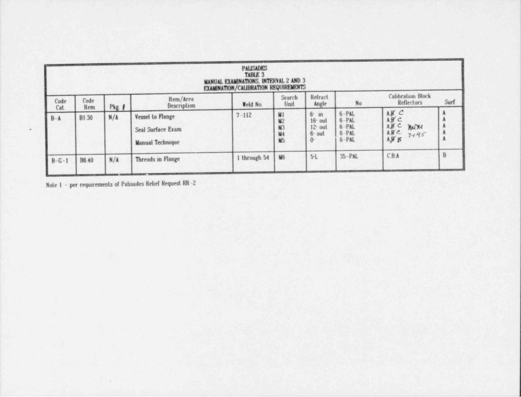
PAljSADES
TABLE 3MANUAL EXAMINAfl0NS. INTERVAL 2 AND 3
EXAIANAfl0N/CAIJBRAT10N REQUIREMENTS
Code Code item / Area Search Refract Cahbration Block
Cat. Item Pkg.I Description veld No. Unit Angle No Reflectors Surf
d A
AK'cB-A Bl.30 N/A Vessel to Flange 7-112 Mt 6- in 6-PALAS AM2 16 out 6-PAL
Seal Surface Exam W3 12 out 6-PAL AKC hw A'
M4 6 out 6-PAL AKC pg A
Manual Technique M5 0- 6-PAL Ay'j!; A
B-C-1 B6.40 N/A Threads in Flange I through 54 M6 5-L 35-PAL C.B.A B
Note 1 - per requirements of Palisades Relief Request RR-2
_ _ _ _ _ _ _ _ _ _ _ _ _ _ _ _ _ _ _ _ _ _ _ _ - _

_ _ _ _ _ _ _ _ _ _ _ _ _ _ _ _ _ _ _ _ _ - _ _ _ _ _ _ _ _ _ _ _ _ _ _ _ _ _ _ _ _ _ _ _ _ _ _ _ _ _ _ _ _ . _ _ _ _ _ _ _ _ . _ _ _ . _ _ _ _ _ - _ _ _ _ _ _ _ _ _ _ _ _______________ __-.
,
r
VIEW FROM TOOL CENTER LINETOP SLED BOTTOM SLED
1.00 1.00= = = =
$ ._J
W$ .
$e $+- S
"* 1.00 m m mW ' '
_ ; i i i
h 1.00 ho-+ -+m+- 8g. m: -
.ma m m m m
.
g%*
13.02= =
REFRACTEDTRANSDUCER ANGLE DIRECTION
S1 70*L CW/DOWN ROTATE CCW 90*40mm TRANSDUCER S2 70*L CCW/UP j FOR 'A' AXIS
CASE SIZE S3 45*S CW/DOWN SCANNING.S4 45*S CCW/UPSS 0*L ---
S6 60*S CW/DOWNS7 +45'L CCW/UPS8 60*S CCW/UP
* SIZING TRANSDUCER
PaEsades - Shen Weld Scan Sleds

_ _ _ - _ _ _ , _ _ - - _ _ - - . . _ _ _ , . _ _ _ , _, -__ _ _ _ _ _ _ - _ . . . , - - _ _ , , . , _ _ _ _ _ - _ _ . _ _ - _ _ _ _ _ _ - _ , . _ _ , _ _ , ,
LOWER HEAD TRANSDU ER SLEDSVIEW FROM TOOL CENTER LINE
' m{ S6 S1 58o +- +- -+
h_ _J Wiii m~ aw -
8$ N S3 S2 S4+- -+ -+
.
P
ROTATE 90* CCWFOR 'A' AXIS SCANS
REFRACTEDTRANSDUCER ANGLE DIRECTION
S1 70*L CW / DOWN'52 70*L CCW / UPS3 -45*S CW / DOWNS4 45 S CCW / UPS6 60"S CW / DOWN -
S8 60*S CW / UP
. PALISADES - 6 POCKET SHELL WELD SCAN SLED
!
.-- __ _ _ _ . . _ _ = _ _ - _ _ _ _ = _ _ - _ - _ _ _ _ _ _ _ _ - _ _ _ _ - - - _ _ _ _ - _ _ _ _ _ _ - _ - _
- _ _ - _ _ _ _ - _ _ _ _ _ _ _ _ _ _ _ _ _ _ _ _ _ _ _ _ _ _ _ _ _ _ _ _ _ _ _ _ _ _ _ _ __ ____ . _ . . _ _ _ _ _ _ _ . . _ _ _ _ _ _ _ _ _ _ _ _ . _ _ _ . _ _ _ _ _ _ _ _ _ _ _ _ _ _ _ _ _ _ _ _ _ _ _ _ _ _ _
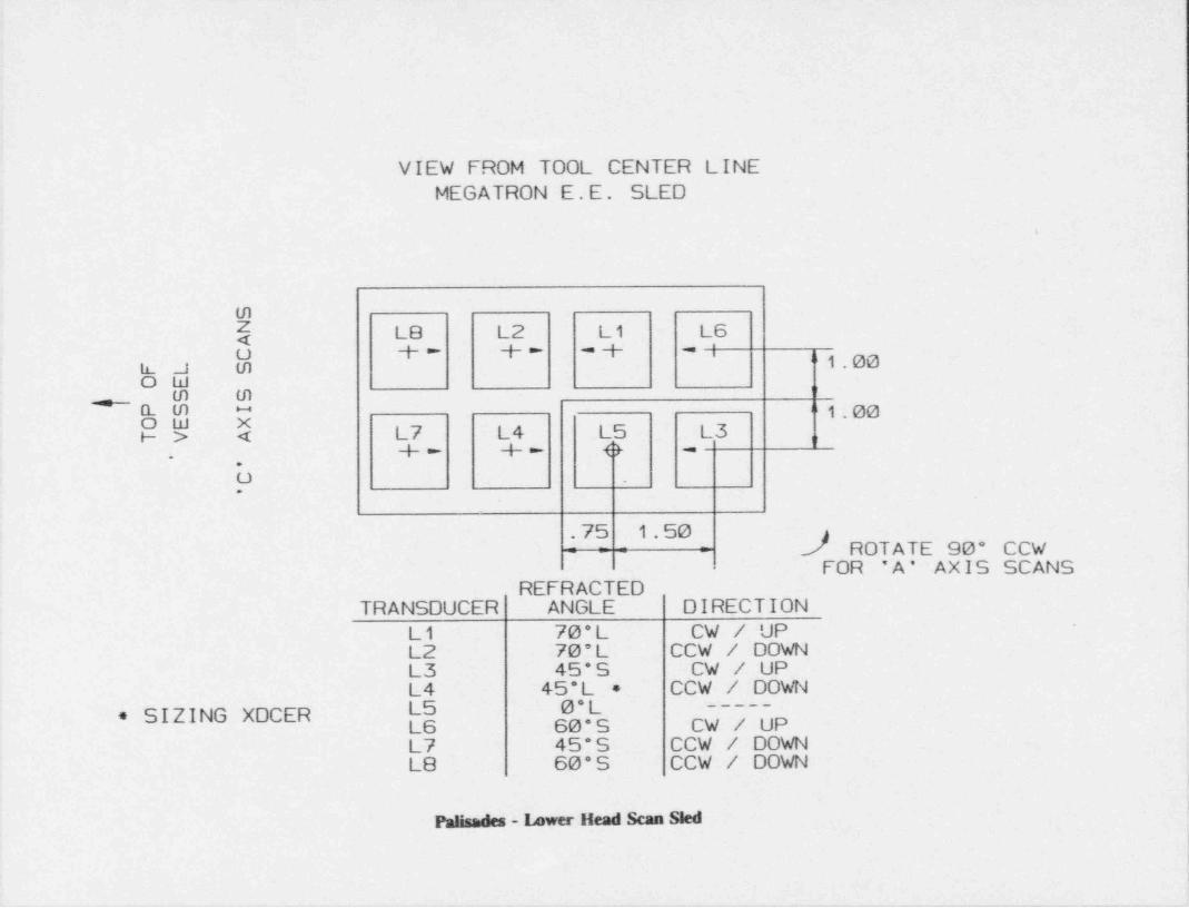
VIEW FROM TOOL CENTER LINEMEGATRON E.E. SLED
L
m
( L8 L2 L1 L6o +- +- -+ -i h 1.00h_ J m
ow om m@@ Q 1.00"
i- > < L7 L4 - L5 L3 n+- +- e -
.,
O .
.
.75 1.50 2_/ ROTATE 90* CCW-= = = =
FOR 'A* AXIS SCANSREFRACTED
TRANSDUCER ANGLE DIRECTION '
L1 70*L CW / UPL2 70*L CCW / DOWNL3 45*S CW / UP
CCW / DOWNL4 45*L *0* SIZING XDCER 60*S CW UP
L7 45"S CCW / DOWNL8 60*S CCW / DOWN
|
Palisades - 14wer Head Scan Sted
,
i
_ _ _ _ _ _ _ _ _ - _ _ _ _ _ _ - _ - _ _ _ - _ - _ _ - - _ - _ _ _ _ _ _ _ _ - _ _ - _ _ _ _ - - _ _ - _ _ _ _ _

>
VIEW FROM TOOL CENTER LINE< '
.{t .
180* SLED0* SLED
\ SAFE ENDAX-OUT"
1.785BI B2 B3
_ _ _ _ _ _
B _
o , o
VESSEL5 785 CENTER
AX-IN"
l.89 1.89
REFRACTEDTRANSDUCER ANGLE DIRECTION |
BI 30*L AX-IN-
;
B2 IO*L AX-IN i
B3 50*L AX-IN
B O* Focused (supplemental)J
l,
'
|
|Palisades - Nozzle Bore Scan Sleds, inner pair
:
_ _ _ _ . _ . _ _ _ _ _ _ _ _ _ _ _ _ _ _ _ _ _ _ _ _ _ _ _ _ _ _ _ _ . _ _ _ _ . _ ___

__ _ _-__ -. _ _ _ _ . _ _ .. ___ _ ____-_-- _______ __-_____ ____ __ _ _.
NOZZLE BORE TRANSDUCER SLEDS'
' VIEW FROM TOOL CENTER LINE90* SLED270* SLED DOCKING POSITION
1.14 1.141 . 1 4 1 . 1 4_ ._ - . -
.
,
_ -. - -
,
II
SAFE ENDAX-OUT
B11 & B8o
__ __ + __
"B12 B7 "" "
i 31i1.311 B6 m
@ --+ VESSEL ,
m
i 3111.311 B 10 B4 B5 m
4 *,,
~+ +" AX-INB9
o
REFRACTEDTRANSDUCER ANGLE DIRECTION
B12 45*S AX-OUT (0.0. EO.) .
.'
B11 45*S AX-IN (O.D. EO.)B4 70*L CWB5 70*L CCWB6 0* ---
B7 70*L. AX-OUTB8 70*L .AX-INB9 45*S CW (O.D. EO.)B10 45*S CCW (0.0. EO.)
,
Palisades - Nesde Bere Scan SW oder pair
- _ _ _ _ _ _ - - _ - - _ _ _ _ _ _ _ _ _ _ _ _ - - - _ _ - _ _ _ - _ _ _ - - _ _ _ _ -

VIEW FROM TOOL CENTER LINE
"
REFRACTED ,l 'I " '," "
TRANSOUCER ANGLE DIRECTION iT1j(T6j Ti 45*S CCW
T2 60*S CCW i'
T3 0* CCW[o]T4 70*L CCW
nTS 70*L CW
T6 45*S * CW T2)T5 T7 60*S CW
T8 45'S CW
So xsomTOOL
_1.08" C.L.";
3#"3 *4.00"
TYP.63"
1.69" T4-(T7j TYP. yo,
' 1.69" [""
b TYP. ~-g
NOTE: ALL EXAMINATION HEADS(TB) ARE SKEWED 10* TO TRACK (T3j
THE NOZZLE TO SHELL WELD.
* TRANSDUCER SKEWED 15* IN.
Palisades - Nozzle tangential Scan Sleds. _ _ _ _ _ _ _ _ _ _

i. ' ' i ||||lll1 ||i | ; '
ii
t 'j
*
-
.
.
MM RR AE AN TT E sI
E L d sL adL T eaT U HeR U O n HE O a nT c a* S cN * 0 SE 0 8 R R1 IC L L I
L ' * * L el e
* zl*
0 O 0N 77OL O z z0 ? 7- 0 ozO No-
5 -O - 4 - 6 N3 - tRT - R - e tR R l eI I t lI I
M unOIO -.R
hNF
WE t
aPI
V
.
,

. _ _ _ _ _ _ _ _ _ _ _ _ . _ _ _ _ _ _ _ _ _ _ - _ _ _ _ _ _ _ - _ _ _ _ _ _ - _ _ . _ _ _ _ _ .
,
VIEW FROM TOOL CENTER LINE p i ..
.
*
O' 6' 12* 16' 6'
.1_ J u J u4 _y_
MS M4 M3 M2 Mi:
.
VESSEL CENTER
lf
pan ada. - RAnnual Flange Examination Sled. - -_. - _ _ _ _ _ _ - _ _ _ _ _ _ _ _ _ _ - _ _ - _ _ _ _ _ - _ _ _ _ _ _ _ _ _ _ - _ _ _ _ - _ ._ _ _ - _ _ _ _ _ _ _ _ _ _ _ - - _ - _ _. _ _ - _ - - - -

6> > { t- > : r k { tI ! > 4 t
_
-
_
*
_.
'. ._
" _
_gI
__
_
}_
i
.
_
-Rn 8
a R EE .
ls_le ewWL3
etl8" E _
l E
Wews. I
2 = " ps S A7Iu5 s2, 2 0.
0 ao ER.SI
Cs LA73 5 e 2P 4
d D" O - le 2nN8e K M_ s Oo.f 4
. h. ~.
NCI48ss1__. C _eI
lC O " A7. _
0|'
EE L tC6C4_
# S EI6 Ef|_ ~ _ E- s 2SR.2S _I
* ._ E- e 4g 3 SE8 29S8 _
8&WE_ :- f- E 95 N~ Se_
b
ul _ : - "l s T GN A ..
7k _ : - ee
m Ns1aDNAetSD 2 A s
_ : ~ - E. E- * gIB u *A D A 2 _ :.~ SR ; l_ECl38T _A
QW4 R N 2 _ ~ . N_
REAP 2.5E0Ae _
[ D 0 A EA" s . CSfR6ABO O _ A 8
_ 64 i "0
, -I C R 1 _Z T
O . N C I C ,2 - E.
_o E* 0S S Eu u.* T
"5 2 "5 Os 5 A.
Ds77 .-.A
s. , OR 00 ~
- "o-,
_- I' R -
I_
~ ~ , - -.
I4A S'
" A I_
woa kH f cg 9_ ofgAm ' l
. g Bg
#m aln 'f np i
e. " o. t
" . 3 ie S, 2 at7
6 rg7 g b
il
. aC
-A S
N -.O= E^
h0 C
I
SC_ 4 A N
NB E
Ml
O dsI
i
" 3 N 2 I. Pa t-
6 e -ls .o C. u6 r g. cC p S ^ Cf Ae S s.0 ih8 1
s 8_
_BA* - et88B8 s
l{.
. o N_
O 4 . N SOS A A3 O- I6 8. TI
CT8 A H7 ., I
E4 EAo ,
C IE IRAS FU
= M2 * ED"5 2 | Rlm. 8 o. .A , f8
.
g - e G4T , N(. D- 8
S 45
0- ICBB ^ W.
St A0m lA R6m e DA*
-em eA E
"7 I TS O2
N3
'
.
.
1

- .
ZC-
f-
l
N Z NW
|O Q'h'a
T !'
| C x1 = N
..
V Ds: I .
C5. I z
.. -----.. .
NO W10 9: 4_
9m; di :-
E h
-. .
L<h4M : + 5
"W 5 ~N.f " a- <-
= n.i I O S*%
' ;
I, "*- s A d*
| atI t 8
r a a n r--------- iiia ^* -
*
I) h-
'k*s*%*
oO =nse =.' j b" !'1 /= ~ -
/y'
% CU. o~
-
Ze 3I/ k~ .s~ i ,,
'/ / Ss! 5's$b | = Eps ; f ==d
'n <' Ws 7 ~~
o. s.
.g .i g
b'I O N $ f\
M-m- e.
9 4 - e. awn-/ *-
4$ | b,
I1
| < -
e- $ , O
3 ! ,., )' 'k I$ I,--
,* Wg
| LO " O <j, N =0| C "* '.O O 1 ~ m| C W '_ fu
|, g e o n.: - .
, n.-
z;(,
n e =: I . . ., .- ,
n r. . .v y'
#. M ",
./,['< hM yl jii .
,
[ @ .* I
|N ==i 1
-'
! = i-_
* 3, *|
'
| 2f
- N+_ .
|
Ii
|

_ _ _ _ _ . . _ . . _ - _ _ _ _ . . _ . . __. .
.
_
:--.
O1
| ____________L_i_4_______ ___
.
I i i1
|:::: -u-| e ie te_, - ii i i I
J HGi
| wasv.m -
iti
_
_.__
(._ _ m._,- _ _ _ .
-
,
44,i ~AnM (| : F.tsi hw6-
_ ___ __ . _ _ _ _ _ _ . .
' l
'[.'[fyynue 7.-
NJhPIPML9=
J.p m e es v + g'~ '- .
-. N-
%
090% .6
Palisades - Calibration Block 19-PAL

I
i
i*
1
:-
I I~ .
E~ ! .4_ 4 _ .
s
. _ _ _ ..- - -I
I I i j;
- MiHHE E*EG- | | ||-saac ves>-- i i i
| I I i,
passr::: JHG |1
!o31
i-
gi ,'eis
<
i
i,!
I.
1
,i [ I ii'
').
!i
!,
.i>
: i
|
: i
i; i
1 i'
4
isto<: sci-% !':
'
HT 3P-agy0 \,! :: rmee J~~~4
,
; NA - N |''
:-- ::| Gn~. 9
,,;
l|'' ~4
/'
1
4 i4
09 :09
)i
!,
I|
1
li
I,
)Palisades - Calibradon Block 26. PAL,
_ _ _ _ _ _ _ _ _ _ _ _ _ _ _ __ _ _ _ _ _ _ _ . _ _ _ _ . _ _ _ _ _ _ . . _ _ _ _ _ _ _ . _ _ _ _J

!r 1
i I,
'
A A-
n r o n=-n*
7.001. |22.00 0,--
il il ||""
a '
nU i
-
U __U U .0 |
0 [! f! k / |'
nn
l.75 -
NE
1 24.002.50 ==
5.25b # ^**
3.50 f 3.50l.75
F .750
/+3 E 3.500
A - D B.250R T
7
T&SuaPact A .218 CL Ab
NOM84 R blRECTION OFREF WELD BE AD5 DR IL L & REAM
.312 f.005 Dl AX 3.50 DEEP6 HOLES
1
|||
.
Path - Calibradon Block 35-PAL

---_-------.----_7-- . _ - - - - - - - - - - --
1l
||
.
l1
- .
M
..
-o.o- e n..*M
,
J\[
~'~, ,
::i g , i ,g n,,'. ig i , .__ _ _ _ . . . . . _ . . . - . _g,,
f$ lit l'i is | |'
| _ ] '._ _ _f. .. . !! d! I Ii
I
: 2ti.so ; ,
1|
|:
I% 1.,s a
I'#*1 +- 27a f(~ mg / 250
'
4 1.ns it- \
I j )
['
1~ ' ,# J,T,7 '* av** as J 3.u.-
. - - . . ..o _______
g*ap .
7 "' % 4
N,,, i faee..vuwon yw_ *-.
"| $1A Mf $uf fgg 8
Aff
1
|
||
|
|
|i
11
Palisades - Calibration Block 36-PAL
|
_. . _ .-
:
'_
I
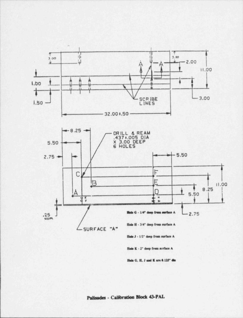
i 'i i i i n'l' i i 3.e.
3. =
A [UV -A- ' -2 oo*
"u d 11.0 0
u
bbb k [~!.' h a"f.bo?; ? ?; \\ / |i " if~~
n n i i i
R - 3.001.B0 - $9dE
= 32.00 f.50 r
4
-+- 8 . 2 5 +DR ILL & RE AM4
.437 8.005 DI AX 3.00 DEEP5.50 : ='
6 HOLE 5'
= : 5.50..
2. 7 5 -*- +.
/. "
C / l-
b .bi II.00" 8.25
.A o o5.50,
i 'c,, ;,y t[
y' It O F ap
==mr| |il
Edo G 1/4" deep tresa surthee A - 2.75,
{ 45 .
1 NomHeis H 3/4" deep freen surface A
,,
Bois J 1/2" deep from surface A
Bete E 2" deep frees avface A
Bete G. H. J and E are 0.125" des
PmHenden - Calibration Block 43-PAL
.
__
.
Ii
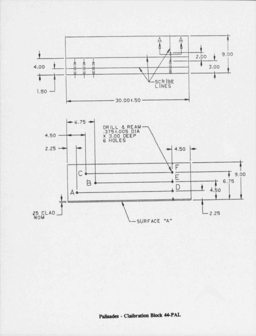
A A o
b h/ \
"9.b0a '
4
2.00 y'
[j n"3-4.00
ik i: |i \ / | |y
i I I na n BChl, tb
LINE51.50 - |
'
30.00 f.50 ==i
i
|
+ 6.75 +DR ILL & RE Ap |'375 f.005 Di
4 50 - -
X 3.00 DEEP- -
6 HOLE 5j2.25 + + 6 4.50 +
\. "
C " 9-E
b h 6.750 t 4,yg1A.
o o o
1 .
na
25 CL AD- - 2.25'
H0M50RF ACE "A"
N - Claibradon Block 44 FAL

.-. . -
!
o 12.00 MIN E'( io 15 -9 437 DRILL & RE AMd 9.25 r' 3.50 DEEP 3 WOLES
~ 6.12 + l
- p,'l Nq o. JM 3.00 - h
.
a
Eo-- - etrs : C"
17.50
Do
:Bess:: o 2 oo !'"12.0 0
* *:+ An
|
6.50C SC L, - 45 -P AL
N/S HT.218993o
|o q y y,
_
a
.
' hoh^ 4.00 M IN >~
e
B.so \-iw
.
Pausades - CaHbrsUon Block 45-PAL-

,
,
)
I
i
l
|
>
$8 lnR3 / \R ~ 4 5' / \3 * 3s l
Y 'A | AM l"
m * \// \
C uLJ
a
j
:
;
- 3.00 3.00 --;
.1.50 - -
!!
Il
+
15.
14 ' | 17 ,
7.25oo
I !o4.20 } 13 B { 3.75 1; 16
2.70 2.25'
'1.50 SA516 PIPE g 10 , 11 g 12 o o
u u
g g i I "
,
2.25 i
7 8 9 }4
A5ae 5.00li N 4 5 6 {F. CIRCULAR VELD PIECE
'
t - - _
|1 2 ( 3) 1.25 1
,
%s' f
.--------------------------------------
7.25
A50 N0ZZLE PIECE
.------------ ----- p?q -----------------"
! !
Palw - Calibration Block NZL-MEP-52
,

..- -- . . . -. . . .. . _..-- .. _ . _ _ - _ _ . --__
l
4
i
ATTACHMENT 4
l
CONSUMERS POWER COMPANYPALISADES PLANT
DOCKET 50-255l
i
'|
|!
| RESPONSE TO REQUEST FOR ADDITIONAL INFORMATIONi INSERVICE INSPECTION PROGRAM i
,
BASIS DOCUMENT - ASME CODE BOUNDARIES,
, ,
I:
|
..