
754002000200008 Oc
100
7/14/2019 754002000200008 Oc http://slidepdf.com/reader/full/754002000200008-oc 1/100 Product Description iManager M2000 Mobile Element Management System V200R008 Issue V1.1 Date 2008-09-28 HUAWEI TECHNOLOGIES CO., LTD.
description
ddd
Transcript of 754002000200008 Oc
7/14/2019 754002000200008 Oc
http://slidepdf.com/reader/full/754002000200008-oc 1/100
Product Description
iManager M2000 Mobile Element Management System
V200R008
Issue V1.1
Date 2008-09-28
HUAWEI TECHNOLOGIES CO., LTD.
7/14/2019 754002000200008 Oc
http://slidepdf.com/reader/full/754002000200008-oc 2/100
Issue V1.1 (2008-09-28) Commercial in Confidence Page 2 of 100
Huawei Technologies Co., Ltd. provides customers with comprehensive technical support and service. Please feel
free to contact our local office or company headquarters.
Huawei Technologies Co., Ltd.
Address: Huawei Industrial Base
Bantian, Longgang
Shenzhen 518129
People's Republic of China
Website: http://www.huawei.com
Email: [email protected]
Copyright © Huawei Technologies Co., Ltd. 2008. All rights reserved.
No part of this document may be reproduced or transmitted in any form or by any means without prior written
consent of Huawei Technologies Co., Ltd.
Trademarks and Permissions
and other Huawei trademarks are trademarks of Huawei Technologies Co., Ltd.
All other trademarks and trade names mentioned in this document are the property of their respective holders.
Notice
The information in this document is subject to change without notice. Every effort has been made in the preparation
of this document to ensure accuracy of the contents, but all statements, information, and recommendations in this
document do not constitute the warranty of any kind, express or implied.
7/14/2019 754002000200008 Oc
http://slidepdf.com/reader/full/754002000200008-oc 3/100
iManager M2000 Mobile Element Management System V200R008
Product Description
Issue V1.1 (2008-09-28) Commercial in Confidence Page 3 of 100
About This Document
Author
Prepared by Jin Feng Date 2008-09-28
Reviewed by Lin Guixiao, Li Yan, Pan
Yungao, Du Yuguo, Lu Yi,Mao Yanqing, Lin Haifan,Wang Wei, Liu Ying, Xu Yi,Xiao Yong, Chen Xiao, ZhangBing, Peng Zhiping, WangJianfeng, Yu Dongchun, ZhouZhenglan, Lang Jianyu
Date 2008-09-28
Approved by Xu Kanlie Date 2008-09-28
Summary
This document describes the features, system structure, functions, and technicalspecifications of the M2000.
This document includes:
Chapter Details
1 Introduction to the M2000 The concepts, network position, and managedNEs of the M2000.
2 Key Benefits The architecture, networking mode, interfaces, andfunctions of the M2000.
3 System Architecture The hardware structure, software structure, andoperation environment of the M2000.
4 Services and Functions The services and functions of the M2000.
5 Reliability The reliability of the M2000 software andhardware.
6 Technical Specifications Technical specifications of the M2000, such asperformance specifications, hardware reliability
specifications, and safety specifications.
7/14/2019 754002000200008 Oc
http://slidepdf.com/reader/full/754002000200008-oc 4/100
iManager M2000 Mobile Element Management System V200R008
Product Description
Issue V1.1 (2008-09-28) Commercial in Confidence Page 4 of 100

7/14/2019 754002000200008 Oc
http://slidepdf.com/reader/full/754002000200008-oc 5/100
iManager M2000 Mobile Element Management System V200R008
Product Description
Issue V1.1 (2008-09-28) Commercial in Confidence Page 5 of 100
History
Issue Details Date Author Approved by
V1.0 First formal release 2008-03-25 Jin Feng Liu Jinhu
V1.1 Second formal release 2008-09-28 Jin Feng Xu Kanlie
V1.2 Feature FARS added 2008-11-28 Zhang Ying Chen Xiao
7/14/2019 754002000200008 Oc
http://slidepdf.com/reader/full/754002000200008-oc 6/100
iManager M2000 Mobile Element Management System V200R008
Product Description
Issue V1.1 (2008-09-28) Commercial in Confidence Page 6 of 100
Contents
1 Introduction to the M2000 ............................................................................................11
1.1 About the M2000 .............................................................................................................................11
1.2 Position of the M2000 in the Network .............................................................................................11
1.3 Managed NEs................................................................................................................................. 12
1.3.1 UTRAN NEs .......................................................................................................................... 12
1.3.2 GBSS NEs............................................................................................................................. 12
1.3.3 CN NEs.................................................................................................................................. 13 1.3.4 uBro NEs ............................................................................................................................... 13
1.3.5 IMS NEs ................................................................................................................................ 13
1.3.6 Transmission and Other Devices .......................................................................................... 14
2 Key Benefits ..................................................................................................................15
2.1 Challenges and Trends .................................................................................................................. 15
2.2 Advanced Architecture ................................................................................................................... 15
2.3 Flexible Networking Mode.............................................................................................................. 16
2.4 Various Interfaces........................................................................................................................... 16
2.5 Powerful Operation and Maintenance Functions........................................................................... 17
2.6 Comprehensive Operation and Maintenance Solution .................................................................. 17
3 System Architecture .....................................................................................................19
3.1 About This Chapter......................................................................................................................... 19
3.2 Physical Structure .......................................................................................................................... 19
3.2.1 Overview................................................................................................................................ 19
3.2.2 Physical Structure of the Single-Server System.................................................................... 20
3.2.3 Physical Structure of the HA System..................................................................................... 20
3.2.4 Typical M2000 Server Configuration ..................................................................................... 21
3.2.5 Typical M2000 Client Configuration....................................................................................... 25
3.2.6 Typical CME Server and Client Configuration....................................................................... 26
3.3 M2000 Operating Environment ...................................................................................................... 28
3.3.1 Operating Environment for the M2000 Single-Server System.............................................. 28
3.3.2 Operating Environment for the M2000 HA System ............................................................... 29
3.4 Software Architecture..................................................................................................................... 29
3.4.1 Overview................................................................................................................................ 29
3.4.2 M2000 Server Software......................................................................................................... 30
3.4.3 M2000 Client Software .......................................................................................................... 32
3.4.4 NE Mediation Software.......................................................................................................... 33

7/14/2019 754002000200008 Oc
http://slidepdf.com/reader/full/754002000200008-oc 7/100
iManager M2000 Mobile Element Management System V200R008
Product Description
Issue V1.1 (2008-09-28) Commercial in Confidence Page 7 of 100
3.5 Interfaces........................................................................................................................................ 33
3.5.1 Northbound Interfaces........................................................................................................... 33
3.5.2 Southbound Interfaces .......................................................................................................... 33
3.5.3 Internal Interfaces.................................................................................................................. 34
4 Services and Functions................................................................................................35
4.1 Topology Management................................................................................................................... 35
4.1.1 Topology Object Management............................................................................................... 35
4.1.2 Topology Object Viewing ....................................................................................................... 35
4.1.3 Topology Map Management.................................................................................................. 36
4.1.4 Shortcut Operation Access.................................................................................................... 36
4.2 Configuration Management............................................................................................................ 36
4.2.1 Configuration Data Synchronization...................................................................................... 36
4.2.2 Configuration Data Query...................................................................................................... 36
4.2.3 Configuration Data Export ..................................................................................................... 36
4.3 Centralized Fault Management...................................................................................................... 37
4.3.1 Real-Time Alarm Monitoring.................................................................................................. 37
4.3.2 Alarm Data Management....................................................................................................... 37
4.3.3 Alarm Query and Statistics .................................................................................................... 38
4.3.4 Alarm Assisting Handling....................................................................................................... 38
4.4 Centralized Performance Management ......................................................................................... 38
4.4.1 NE Performance Measurement Setting................................................................................. 38
4.4.2 Real-Time Monitoring of Performance Results ..................................................................... 39
4.4.3 Performance Result Query.................................................................................................... 39
4.4.4 Performance Data Management ........................................................................................... 39
4.4.5 Performance Alarm................................................................................................................ 40
4.4.6 Custom Counters................................................................................................................... 40
4.4.7 Performance Report .............................................................................................................. 40
4.5 Centralized Security Management................................................................................................. 41
4.5.1 User and User Group Management ...................................................................................... 41
4.5.2 User Authority Management.................................................................................................. 41
4.5.3 User Monitoring ..................................................................................................................... 42
4.5.4 Terminal Locking.................................................................................................................... 42 4.5.5 Security Policy Setting........................................................................................................... 42
4.5.6 Log Management................................................................................................................... 43
4.5.7 OM Transmission Security Management .............................................................................. 44
4.6 System Management ..................................................................................................................... 44
4.6.1 License Management ............................................................................................................ 44
4.6.2 Online Help............................................................................................................................ 44
4.6.3 System Status Monitoring...................................................................................................... 45
4.6.4 Centralized Scheduled Task Monitoring................................................................................ 45
4.6.5 Individual Setting ................................................................................................................... 46
7/14/2019 754002000200008 Oc
http://slidepdf.com/reader/full/754002000200008-oc 8/100
iManager M2000 Mobile Element Management System V200R008
Product Description
Issue V1.1 (2008-09-28) Commercial in Confidence Page 8 of 100
4.6.6 System Data Backup and Restore ........................................................................................ 46
4.6.7 System Uninstalling ............................................................................................................... 46
4.6.8 Client Remote Access ........................................................................................................... 46
4.6.9 Citrix-Based Client Access .................................................................................................... 46
4.7 Time Management for the Entire Network ..................................................................................... 47
4.7.1 Time Zone Management ....................................................................................................... 47
4.7.2 DST Supported...................................................................................................................... 47
4.7.3 Time Synchronization for the Entire Network ........................................................................ 47
4.8 UTRAN Specified Functions........................................................................................................... 47
4.8.1 NE Software Management .................................................................................................... 47
4.8.2 NodeB License Management ................................................................................................ 48
4.8.3 RAN Sharing.......................................................................................................................... 48
4.8.4 FTP Encrypted Transmission Based on SSL ........................................................................ 48
4.8.5 UTRAN IP Networking........................................................................................................... 49
4.8.6 NE Data Backup.................................................................................................................... 49
4.8.7 Custom NE Alarms ................................................................................................................ 49
4.8.8 Real-Time Network Monitoring .............................................................................................. 50
4.8.9 Centralized User Management.............................................................................................. 50
4.8.10 NE Configuration ................................................................................................................. 51
4.8.11 NE Resources Monitoring.................................................................................................... 51
4.8.12 Signaling Tracing................................................................................................................. 52
4.8.13 Inventory Management........................................................................................................ 52
4.8.14 OM Script Development ...................................................................................................... 52 4.8.15 NE Automatic Discovering................................................................................................... 52
4.8.16 Network Integration Monitoring ........................................................................................... 53
4.8.17 Graphic Configuration.......................................................................................................... 53
4.8.18 Network Health Check......................................................................................................... 55
4.9 GBSS Specified Functions............................................................................................................. 55
4.9.1 NE Software Management .................................................................................................... 55
4.9.2 Custom NE Alarms ................................................................................................................ 55
4.9.3 Centralized User Management.............................................................................................. 56
4.9.4 NE Configuration................................................................................................................... 57
4.9.5 Inventory Management.......................................................................................................... 57
4.9.6 NE Automatic Discovering..................................................................................................... 57
4.9.7 Network Health Check........................................................................................................... 57
4.9.8 Network Integration Monitoring ............................................................................................. 58
4.9.9 Graphic Configuration............................................................................................................ 58
4.10 CN Specified Functions................................................................................................................ 60
4.10.1 NE Software Management .................................................................................................. 60
4.10.2 NE Data Backup.................................................................................................................. 61
4.10.3 Custom NE Alarms.............................................................................................................. 61
4.10.4 Real-Time Monitoring .......................................................................................................... 61
7/14/2019 754002000200008 Oc
http://slidepdf.com/reader/full/754002000200008-oc 9/100
iManager M2000 Mobile Element Management System V200R008
Product Description
Issue V1.1 (2008-09-28) Commercial in Confidence Page 9 of 100
4.10.5 Centralized User Management............................................................................................ 61
4.10.6 NE Configuration ................................................................................................................. 62
4.10.7 NE Resource Monitoring ..................................................................................................... 63
4.10.8 Inventory Management........................................................................................................ 63
4.10.9 Signaling Tracing................................................................................................................. 63
4.10.10 OM Script Development .................................................................................................... 64
4.10.11 Dual-Homing Management................................................................................................ 64
4.10.12 MSC Pool Management .................................................................................................... 64
4.10.13 Area-Based Privilege Management of Multi-Area Networks ............................................. 65
4.10.14 Audio File Management..................................................................................................... 65
5 Reliability.......................................................................................................................66
5.1 About This Chapter......................................................................................................................... 66
5.2 System Reliability........................................................................................................................... 66
5.2.1 Data Security......................................................................................................................... 66
5.2.2 Operation Security................................................................................................................. 67
5.3 Hardware Reliability ....................................................................................................................... 67
5.4 Software Reliability......................................................................................................................... 68
6 Technical Specifications ..............................................................................................69
6.1 About This Chapter......................................................................................................................... 69
6.2 Performance Specifications............................................................................................................ 69
6.2.1 System Capacity.................................................................................................................... 69
6.2.2 Bandwidth.............................................................................................................................. 76
6.2.3 Data Processing Capability of the M2000 Server.................................................................. 79
6.2.4 Alarm Data Storage Capacity ................................................................................................ 80
6.2.5 Alarm Processing Capacity.................................................................................................... 81
6.2.6 Number of Clients Simultaneously Started on the Server ..................................................... 81
6.3 Physical and Electrical Specifications ............................................................................................ 82
6.4 Reliability Specifications................................................................................................................. 85
6.5 Compliant Safety Standards........................................................................................................... 87
6.6 EMC Specifications ........................................................................................................................ 87
6.7 Environmental Requirements......................................................................................................... 87
6.7.1 Storage Environment............................................................................................................. 89
6.7.2 Transportation Environment .................................................................................................. 91
6.7.3 Operation Environment ......................................................................................................... 94
A Acronyms and Abbreviations ...................................................................................97

7/14/2019 754002000200008 Oc
http://slidepdf.com/reader/full/754002000200008-oc 10/100
7/14/2019 754002000200008 Oc
http://slidepdf.com/reader/full/754002000200008-oc 11/100
iManager M2000 Mobile Element Management System V200R008
Product Description
Issue V1.1 (2008-09-28) Commercial in Confidence Page 11 of 100
1 Introduction to the M2000
1.1 About the M2000
The iManager M2000 Mobile Element Management System (hereafter referred to asthe M2000) is a centralized mobile network management platform developed byHuawei Technologies Co., Ltd. (hereafter referred to as Huawei). The M2000 canperform centralized management on mobile NEs provided by Huawei. These NEsinclude NEs in the GBSS system, NEs in the UTRAN network, NEs in the CN network,NEs in the uBro network and NEs in the IMS network. In addition, the M2000manages the transmission and other devices used in the mobile network.
1.2 Position of the M2000 in the Network
In the Telecommunication Management Network (TMN), the M2000 is on the ElementManagement-layer (EM-layer). The M2000 also provides a network managementinterface for the Network Management System (NMS).
7/14/2019 754002000200008 Oc
http://slidepdf.com/reader/full/754002000200008-oc 12/100
iManager M2000 Mobile Element Management System V200R008
Product Description
Issue V1.1 (2008-09-28) Commercial in Confidence Page 12 of 100
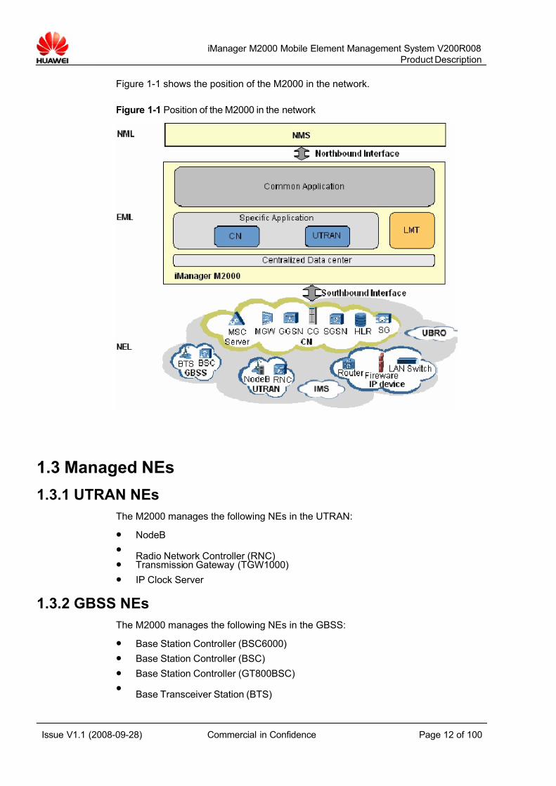
Figure 1-1 shows the position of the M2000 in the network.
Figure 1-1 Position of the M2000 in the network
1.3 Managed NEs
1.3.1 UTRAN NEs
The M2000 manages the following NEs in the UTRAN:
z NodeB
z Radio Network Controller (RNC)
z Transmission Gateway (TGW1000)
z IP Clock Server
1.3.2 GBSS NEs
The M2000 manages the following NEs in the GBSS:
z Base Station Controller (BSC6000)
z Base Station Controller (BSC)
z Base Station Controller (GT800BSC)
z Base Transceiver Station (BTS)

7/14/2019 754002000200008 Oc
http://slidepdf.com/reader/full/754002000200008-oc 13/100
iManager M2000 Mobile Element Management System V200R008
Product Description
Issue V1.1 (2008-09-28) Commercial in Confidence Page 13 of 100
z Packet Controlling Unit (PCU35)
z Packet Controlling Unit (PCU33)
z Packet Controlling Unit (PCU6000)
1.3.3 CN NEsThe M2000 manages the following CN NEs in the CN:
z Serving GPRS Support Node (SGSN)
z Gateway GPRS Support Node (GGSN)
z Mobile Switching Center (2G MSC)
z Mobile Service Switching Center Server (MSC Server)
z Media Gate-Way (MGW)
z Home Location Register (HLR36)
z Home Location Register (HLR9820)
z Home Location Register-Data Node (HLR-DC)
z Home Location Register-Service Node (HLR-SC)
z Charging Gateway (CG)
z Shared Interworking Function (IWF)
z Singling Gateway (SG7000)
The mobile switching center (MSC) is categorized into the following types:
z MSC based on the 32-module architecture, also called MSC33 and G3.
z iMSC based on the 128-module architecture, also called MSC60, VMSC60, IGATE, and G6.
z tMSC in the GT800 trunk communication system, which adopts the iMSC architecture.
z rMSC in the GSM-R railway dispatch system, which adopts the iMSC architecture.
1.3.4 uBro NEs
The M2000 manages the following uBro NEs:
z Access Gateway (AG)
z AP Home Register (AHR)
z IP Clock Server
z Authorization, Authentication and Accounting (AAA)
1.3.5 IMS NEs
The M2000 manages the following IMS NEs:
z Calling Session Control Function (CSCF) (CSC3300)
z Convergent Service Engine (CSE) (CSE9600)
z Home Subscriber Server (HSS) (HSS9820)
z Multimedia Exchange Server (MEDIAX) (MediaX3600)
z IP Centrex (IPCTRX) (ETAS9960)
z Multimedia Resource Function Controller (MRFC) (MRC6600)

7/14/2019 754002000200008 Oc
http://slidepdf.com/reader/full/754002000200008-oc 14/100
iManager M2000 Mobile Element Management System V200R008
Product Description
Issue V1.1 (2008-09-28) Commercial in Confidence Page 14 of 100
z Multimedia Resource Function Processor (MRFP) (MRP6600)
z Resource and Policy Control System (RM) (RM9000)
z Advanced Telephony Server (ATS) (ATS9900)
z Charging Collection Function (CCF) (iCG9815)
z Session Border Controller (SBC) (SE2300)
1.3.6 Transmission and Other Devices
The M2000 manages the following transmission and other devices:
z Routers of NE08 series
z LAN switches of S series
z Firewalls of Eudemon series
z IPsec Gateway
z Domain Name Server (DNS)
z Dynamic Host Configuration Protocol Server (DHCP Server)
z NE Bearing Server The servers that bear the SG7000, MSC Server and iGWB.
7/14/2019 754002000200008 Oc
http://slidepdf.com/reader/full/754002000200008-oc 15/100
iManager M2000 Mobile Element Management System V200R008
Product Description
Issue V1.1 (2008-09-28) Commercial in Confidence Page 15 of 100
2 Key Benefits
2.1 Challenges and Trends
The O&M system in the current telecommunication network faces the followingchallenges:
z With the network expansion and increasingly involved subscribers, how tomanage the network in an effective manner?
z With the rapid development of telecommunication technology, for instance, fromGlobal System for Mobile Telecommunications (GSM) to WCDMA, how can theelement management system (EMS) evolve itself?
z How to speed up network construction to meet the demands of quickdeployment?
z How to solve the problem of resource shortage and high cost brought about bythe central processing of the server?
z Facing the fact that backup complexity increases with amount of data, how to
perform data collection and hardware redundancy?
The O&M system also shows the following trends in its development:
z Integrated network monitoring and maintenance
z Open interface and flexible networking to facilitate the network expansion andevolution
z Service-oriented, active maintenance, and performance management takingplace of device-oriented, passive maintenance, and alarm management
z Network quality evaluation and persistent improvement on service quality
Providing powerful and rich functions, the Huawei M2000 system meets the latestdevelopment trends and helps network operators handle the challenges with ease.
2.2 Advanced Architecture
With the Common Object Request Broker Architecture (CORBA) design, each servicefunction in the M2000 can be developed and deployed through componentizedmodule, which enables the M2000 to meet the maintenance demands in a quickmanner and realize smooth upgrade.
Having several hardware and software platforms, the M2000 also provides typicalconfigurations for these resources to be applied to different networks. The M2000
realizes smooth network expansion based on the increasingly network dimensioning.
7/14/2019 754002000200008 Oc
http://slidepdf.com/reader/full/754002000200008-oc 16/100
iManager M2000 Mobile Element Management System V200R008
Product Description
Issue V1.1 (2008-09-28) Commercial in Confidence Page 16 of 100
2.3 Flexible Networking Mode
The M2000 manages the following network elements (NE) or devices provided byHuawei:
z NEs in the Universal Terrestrial Radio Access Network (UTRAN)
z NEs in the GSM Base Station Subsystem (GBSS)
z NEs in the Core Network (CN)
In addition, the M2000 manages the IP networking devices complying with the SNMPprotocol. In this way, the M2000 can manage the core network and the accessnetwork either in a consolidated manner or in an independent manner.
The M2000 can either execute integrated management on CN and UTRAN or GBSS,or manage the CN or UTRAN or GBSS individually.
The M2000 supports both the GSM and Universal Mobile Telecommunications
System (UMTS) technologies to cater for the GSM's evolution to UMTS.Communicating with NEs based on TCP/IP, the M2000 supports the following types of networks:
z Local area network (LAN)
z E1/T1 network
z Virtual private network (VPN)
2.4 Various Interfaces
The M2000 provides various kinds of interfaces to cater for a wide range of users andsituations.
The M2000 provides the NMS with the following northbound interfaces that complywith the protocol standards:
z CORBA interface
z File interface
z SNMP interface
z Alarm streaming interface
z MML transparent transmission interface
The M2000 manages standard IP networking devices through SNMP interface andmanages devices provided by Huawei through the following southbound interfaces:
z MML interface
z Binary interface
In addition, the M2000 provides a platform for script development. The scriptdevelopment includes:
z Editing, debugging, and running scripts
z Executing tasks on a scheduled basis
You can use the script development platform to edit or run High-level Script Language
(HSL) to realize automatic routine maintenance.
7/14/2019 754002000200008 Oc
http://slidepdf.com/reader/full/754002000200008-oc 17/100
iManager M2000 Mobile Element Management System V200R008
Product Description
Issue V1.1 (2008-09-28) Commercial in Confidence Page 17 of 100
2.5 Powerful Operation and Maintenance Functions
The M2000 provides the following powerful O&M functions:
z Topology management (TM)
z Configuration management (CM)
z Fault management (FM)
z Performance management (PM)
z Security management (SM)
Based on new features of services after the introduction of soft switch in the CN, theM2000 provides the following functions:
z Dual-homing management
z MSC Pool management
z Local network management
z Voice file management
With regard to the configuration complexity of the UTRAN and GBSS, and the largenumber of parameters, the M2000 provides the following functions:
z CME configuration tool for the UTRAN and GBSS
z Software management
z Network integration monitoring
The CME configuration tool for the UTRAN and GBSS allows you to centralize theconfiguration of multiple RNSs in the UTRAN and GBSS. It uses the GUI to configurethe wireless parameters and transmission parameters of NEs. By setting planned
areas and current areas, you can use the tool to check configuration data for reducingconfiguration errors. The function of configuration tool allows you to import theparameters of each interface and network planning parameters. This reduces theefforts of parameter input and the risks caused by the incorrect input of parameters.
2.6 Comprehensive Operation and Maintenance Solution
The M2000 provides a comprehensive O&M solution.
The solution provides:
z The M2000 implements a combination of centralized maintenance and localmaintenance. On the server side, centralized operation and maintenance andlocal maintenance are combined. On the NE side, the local maintenance mode isused. The M2000 supports remote maintenance and user monitoring through thevirtual private network (VPN).
z The M2000 provides an integrated graphical user interface (GUI) for managing allthe network equipment of Huawei's mobile network and the third-party IP devicessupporting the SNMP interface.
z The M2000 provides subnet topology and user management to help the operator manage local NEs.
z Interface message tracing and user message tracing are implemented by the
M2000 software. This helps to locate faults. You need not add other hardwareequipment.
7/14/2019 754002000200008 Oc
http://slidepdf.com/reader/full/754002000200008-oc 18/100
iManager M2000 Mobile Element Management System V200R008
Product Description
Issue V1.1 (2008-09-28) Commercial in Confidence Page 18 of 100
z Report system for daily troubleshooting and the provision of network KPI report.
z Citrix client access solution to enable the remote access of clients.
z Time management to synchronize the time in the entire network.
z The M2000 supports the management of daylight saving time (DST) and multiple
time zones. It also supports the time management of NEs located in different timezones.
z The M2000 provides various northbound interfaces to meet the interconnectionrequirements of different operators.
z System backup restore solution to ensure the data security in the network
7/14/2019 754002000200008 Oc
http://slidepdf.com/reader/full/754002000200008-oc 19/100
iManager M2000 Mobile Element Management System V200R008
Product Description
Issue V1.1 (2008-09-28) Commercial in Confidence Page 19 of 100
3 System Architecture
3.1 About This Chapter
The M2000 system works in client/server mode.
The M2000 software consists of the client software, server software, and NEmediation software. The software is mutually independent. The client software runs onthe client, and the server software and mediation software run on the server.
This chapter describes the physical and software architecture of the M2000 system.
3.2 Physical Structure
3.2.1 Overview
A typical M2000 system consists of the following components:
z A server or servers
z A client or clients
z An alarm box or alarm boxes
z Other networking devices
When you need to configure the data of NEs in the UTRAN and GBSS through theCME, you have to configure a server and a client for the CME.
7/14/2019 754002000200008 Oc
http://slidepdf.com/reader/full/754002000200008-oc 20/100
iManager M2000 Mobile Element Management System V200R008
Product Description
Issue V1.1 (2008-09-28) Commercial in Confidence Page 20 of 100
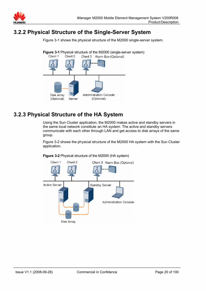
3.2.2 Physical Structure of the Single-Server System
Figure 3-1 shows the physical structure of the M2000 single-server system.
Figure 3-1 Physical structure of the M2000 (single-server system)
3.2.3 Physical Structure of the HA System
Using the Sun Cluster application, the M2000 makes active and standby servers inthe same local network constitute an HA system. The active and standby serverscommunicate with each other through LAN and get access to disk arrays of the samegroup.
Figure 3-2 shows the physical structure of the M2000 HA system with the Sun Cluster application.
Figure 3-2 Physical structure of the M2000 (HA system)
7/14/2019 754002000200008 Oc
http://slidepdf.com/reader/full/754002000200008-oc 21/100
iManager M2000 Mobile Element Management System V200R008
Product Description
Issue V1.1 (2008-09-28) Commercial in Confidence Page 21 of 100
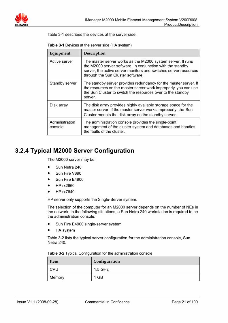
Table 3-1 describes the devices at the server side.
Table 3-1 Devices at the server side (HA system)
Equipment Description
Active server The master server works as the M2000 system server. It runsthe M2000 server software. In conjunction with the standbyserver, the active server monitors and switches server resourcesthrough the Sun Cluster software.
Standby server The standby server provides redundancy for the master server. If the resources on the master server work improperly, you can usethe Sun Cluster to switch the resources over to the standbyserver.
Disk array The disk array provides highly available storage space for themaster server. If the master server works improperly, the Sun
Cluster mounts the disk array on the standby server.
Administrationconsole
The administration console provides the single-pointmanagement of the cluster system and databases and handlesthe faults of the cluster.
3.2.4 Typical M2000 Server Configuration
The M2000 server may be:
z Sun Netra 240
z Sun Fire V890
z Sun Fire E4900
z HP rx2660
z HP rx7640
HP server only supports the Single-Server system.
The selection of the computer for an M2000 server depends on the number of NEs inthe network. In the following situations, a Sun Netra 240 workstation is required to bethe administration console:
z Sun Fire E4900 single-server system
z HA system
Table 3-2 lists the typical server configuration for the administration console, SunNetra 240.
Table 3-2 Typical Configuration for the administration console
Item Configuration
CPU 1.5 GHz
Memory 1 GB
7/14/2019 754002000200008 Oc
http://slidepdf.com/reader/full/754002000200008-oc 22/100
iManager M2000 Mobile Element Management System V200R008
Product Description
Issue V1.1 (2008-09-28) Commercial in Confidence Page 22 of 100
Item Configuration
Hard disk 2 x 146 GB
Accessories DVD/Display card/Ethernet adapter/KVM/User manual
Operating system Solaris 10
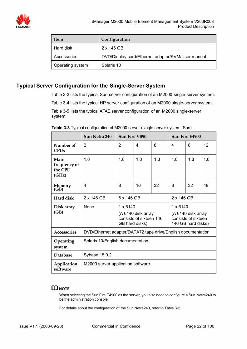
Typical Server Configuration for the Single-Server System
Table 3-3 lists the typical Sun server configuration of an M2000 single-server system.
Table 3-4 lists the typical HP server configuration of an M2000 single-server system.
Table 3-5 lists the typical ATAE server configuration of an M2000 single-server system.
Table 3-3 Typical configuration of M2000 server (single-server system, Sun)
Sun Netra 240 Sun Fire V890 Sun Fire E4900
Number ofCPUs
2 2 4 8 4 8 12
Mainfrequency ofthe CPU(GHz)
1.8 1.8 1.8 1.8 1.8 1.8 1.8
Memory(GB)
4 8 16 32 8 32 48
Hard disk 2 x 146 GB 6 x 146 GB 2 x 146 GB
Disk array(GB)
None 1 x 6140
(A 6140 disk arrayconsists of sixteen 146GB hard disks)
1 x 6140
(A 6140 disk arrayconsists of sixteen146 GB hard disks)
Accessories DVD/Ethernet adapter/DATA72 tape drive/English documentation
Operating
system
Solaris 10/English documentation
Database Sybase 15.0.2
Applicationsoftware
M2000 server application software
When selecting the Sun Fire E4900 as the server, you also need to configure a Sun Netra240 tobe the administration console.
For details about the configuration of the Sun Netra240, refer to Table 3-2.
7/14/2019 754002000200008 Oc
http://slidepdf.com/reader/full/754002000200008-oc 23/100
iManager M2000 Mobile Element Management System V200R008
Product Description
Issue V1.1 (2008-09-28) Commercial in Confidence Page 23 of 100
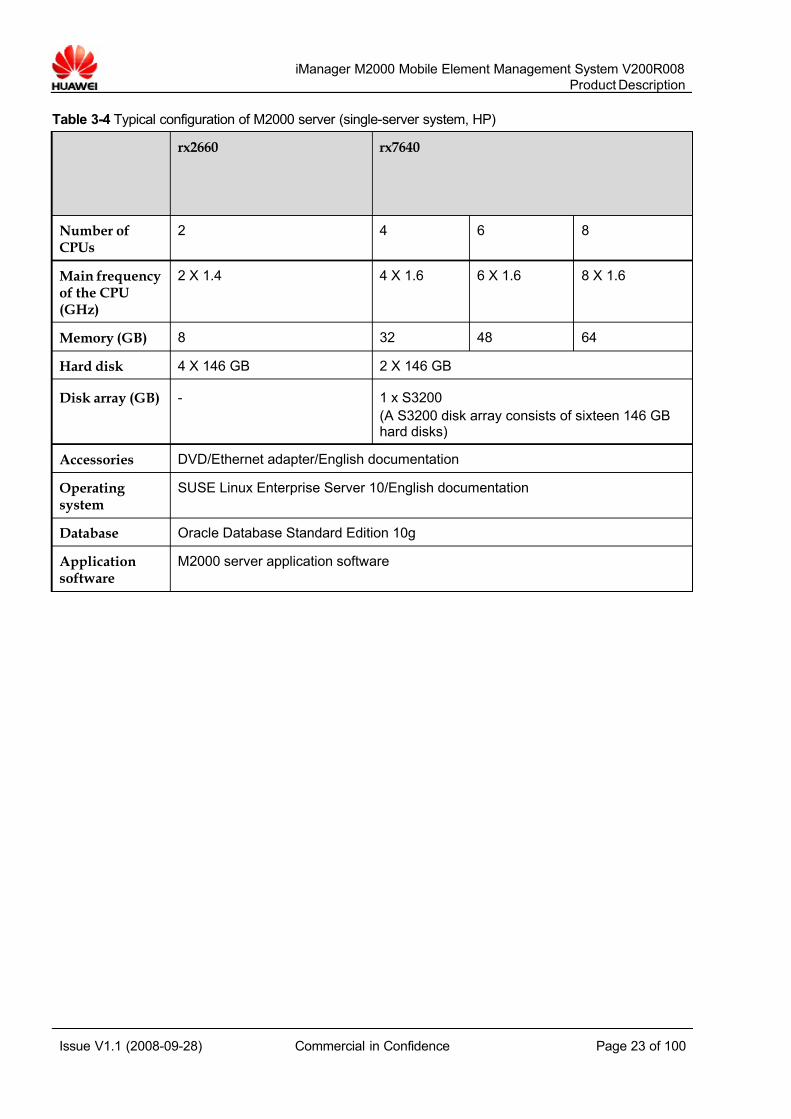
Table 3-4 Typical configuration of M2000 server (single-server system, HP)
rx2660 rx7640
Number ofCPUs
2 4 6 8
Main frequencyof the CPU(GHz)
2 X 1.4 4 X 1.6 6 X 1.6 8 X 1.6
Memory (GB) 8 32 48 64
Hard disk 4 X 146 GB 2 X 146 GB
Disk array (GB) - 1 x S3200
(A S3200 disk array consists of sixteen 146 GBhard disks)
Accessories DVD/Ethernet adapter/English documentation
Operating system
SUSE Linux Enterprise Server 10/English documentation
Database Oracle Database Standard Edition 10g
Applicationsoftware
M2000 server application software

7/14/2019 754002000200008 Oc
http://slidepdf.com/reader/full/754002000200008-oc 24/100
iManager M2000 Mobile Element Management System V200R008
Product Description
Issue V1.1 (2008-09-28) Commercial in Confidence Page 24 of 100
Table 3-5 Typical configuration of M2000 server (ATAE)
Item rx2660
Number of CPUs 2
Main frequency of theCPU
2130 MHz
Memory (GB) 8
Hard disk 2 X 146 GB
Accessories DVD/DATA72 tape drive/English documentation
Operating system SUSE Linux Enterprise Server 10/English documentation
Database Oracle Database Standard Edition 11g
Application software M2000 server application software
When selecting the ATAE as the M2000 server, you also need to configure a USMserver to be the console of installing software on the ATAE server. For details aboutthe configuration of the USM server, refer to Table 3-6.
Table 3-6 Typical configuration of USM server
Item PC Server
Number of CPUs 2
Main frequency of theCPU
1.6 GHz
Memory (GB) 8
Hard disk 2 X 146 GB
Accessories DVD/Ethernet adapter/English documentation
Operating system SUSE Linux Enterprise Server 9 SP02/English documentation
Application software USM server application software
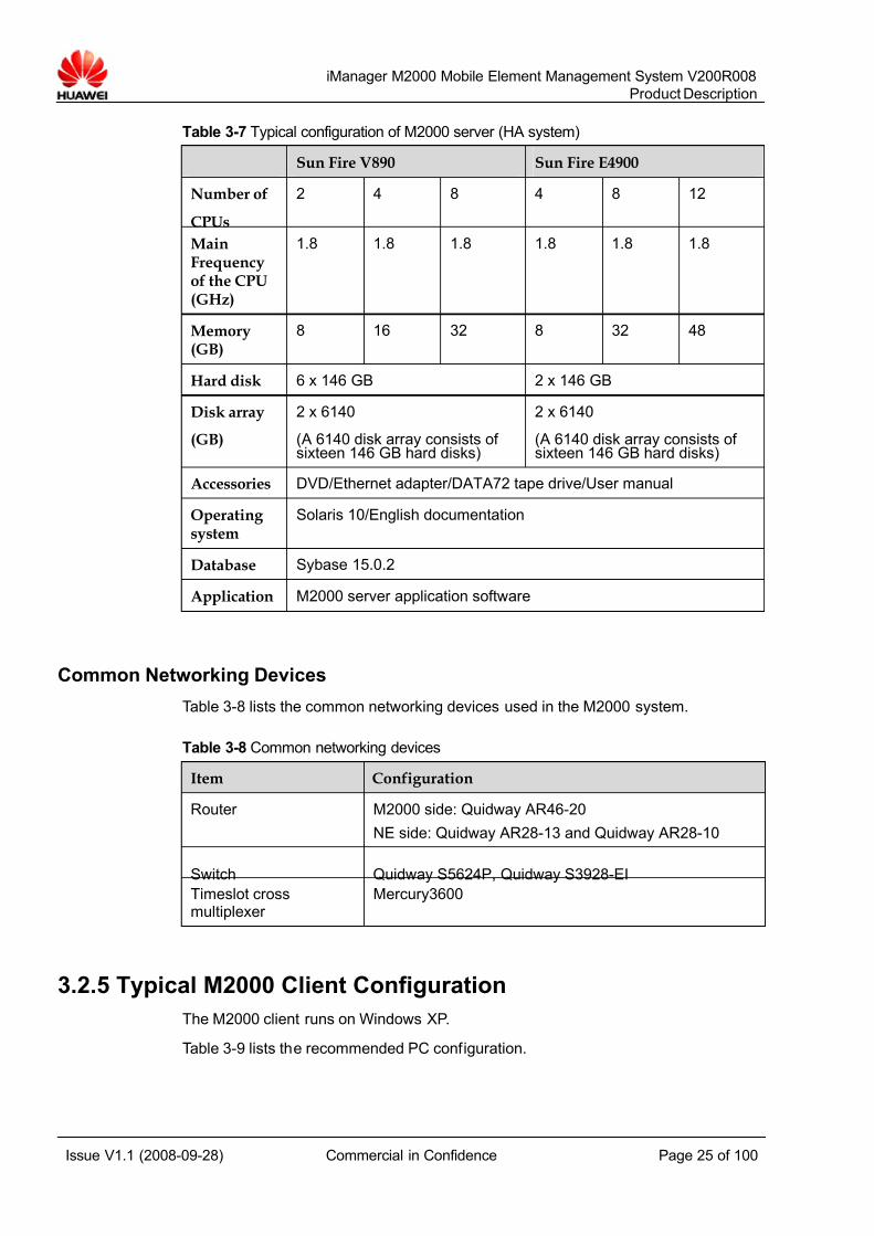
Typical Server Configuration for the HA System
The configurations of the two servers in the HA system (Sun Cluster) are the same.Table 3-7 lists the usable server types and the standard configuration of each server.
7/14/2019 754002000200008 Oc
http://slidepdf.com/reader/full/754002000200008-oc 25/100
iManager M2000 Mobile Element Management System V200R008
Product Description
Issue V1.1 (2008-09-28) Commercial in Confidence Page 25 of 100
Table 3-7 Typical configuration of M2000 server (HA system)
Sun Fire V890 Sun Fire E4900
Number of
CPUs
2 4 8 4 8 12
MainFrequencyof the CPU(GHz)
1.8 1.8 1.8 1.8 1.8 1.8
Memory(GB)
8 16 32 8 32 48
Hard disk 6 x 146 GB 2 x 146 GB
Disk array
(GB)
2 x 6140
(A 6140 disk array consists of sixteen 146 GB hard disks)
2 x 6140
(A 6140 disk array consists of sixteen 146 GB hard disks)
Accessories DVD/Ethernet adapter/DATA72 tape drive/User manual
Operating system
Solaris 10/English documentation
Database Sybase 15.0.2
Application M2000 server application software
Common Networking Devices
Table 3-8 lists the common networking devices used in the M2000 system.
Table 3-8 Common networking devices
Item Configuration
Router M2000 side: Quidway AR46-20
NE side: Quidway AR28-13 and Quidway AR28-10
Switch Quidway S5624P, Quidway S3928-EI
Timeslot crossmultiplexer
Mercury3600
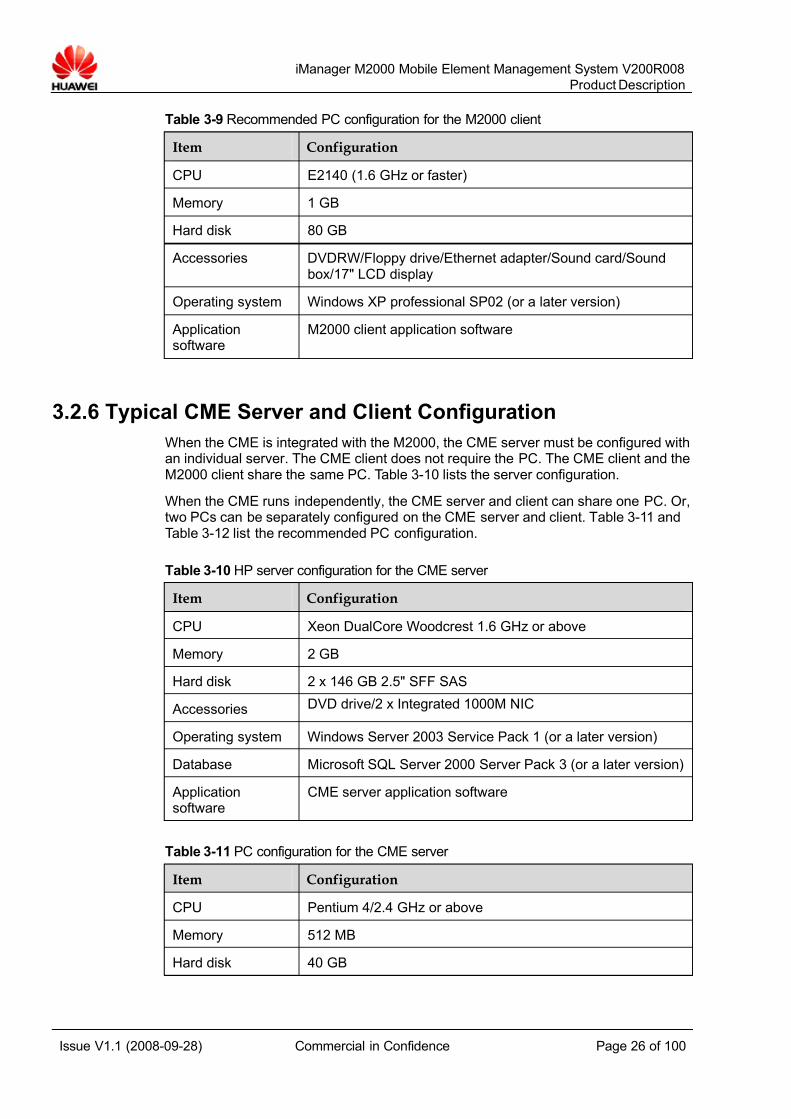
3.2.5 Typical M2000 Client Configuration
The M2000 client runs on Windows XP.
Table 3-9 lists the recommended PC configuration.
7/14/2019 754002000200008 Oc
http://slidepdf.com/reader/full/754002000200008-oc 26/100
iManager M2000 Mobile Element Management System V200R008
Product Description
Issue V1.1 (2008-09-28) Commercial in Confidence Page 26 of 100
Table 3-9 Recommended PC configuration for the M2000 client
Item Configuration
CPU E2140 (1.6 GHz or faster)
Memory 1 GB
Hard disk 80 GB
Accessories DVDRW/Floppy drive/Ethernet adapter/Sound card/Soundbox/17" LCD display
Operating system Windows XP professional SP02 (or a later version)
Applicationsoftware
M2000 client application software
3.2.6 Typical CME Server and Client Configuration
When the CME is integrated with the M2000, the CME server must be configured withan individual server. The CME client does not require the PC. The CME client and theM2000 client share the same PC. Table 3-10 lists the server configuration.
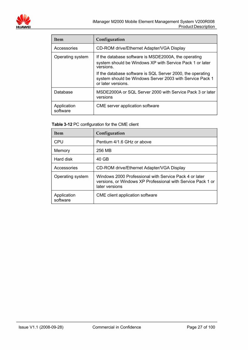
When the CME runs independently, the CME server and client can share one PC. Or,two PCs can be separately configured on the CME server and client. Table 3-11 andTable 3-12 list the recommended PC configuration.
Table 3-10 HP server configuration for the CME server
Item Configuration
CPU Xeon DualCore Woodcrest 1.6 GHz or above
Memory 2 GB
Hard disk 2 x 146 GB 2.5" SFF SAS
Accessories DVD drive/2 x Integrated 1000M NIC Operating system Windows Server 2003 Service Pack 1 (or a later version)
Database Microsoft SQL Server 2000 Server Pack 3 (or a later version)
Applicationsoftware
CME server application software
Table 3-11 PC configuration for the CME server
Item Configuration
CPU Pentium 4/2.4 GHz or above
Memory 512 MB
Hard disk 40 GB
7/14/2019 754002000200008 Oc
http://slidepdf.com/reader/full/754002000200008-oc 27/100
iManager M2000 Mobile Element Management System V200R008
Product Description
Issue V1.1 (2008-09-28) Commercial in Confidence Page 27 of 100
Item Configuration
Accessories CD-ROM drive/Ethernet Adapter/VGA Display
Operating system If the database software is MSDE2000A, the operating
system should be Windows XP with Service Pack 1 or later versions.
If the database software is SQL Server 2000, the operatingsystem should be Windows Server 2003 with Service Pack 1or later versions.
Database MSDE2000A or SQL Server 2000 with Service Pack 3 or later versions
Applicationsoftware
CME server application software
Table 3-12 PC configuration for the CME client
Item Configuration
CPU Pentium 4/1.6 GHz or above
Memory 256 MB
Hard disk 40 GB
Accessories CD-ROM drive/Ethernet Adapter/VGA Display
Operating system Windows 2000 Professional with Service Pack 4 or later versions, or Windows XP Professional with Service Pack 1 or later versions
Applicationsoftware
CME client application software
7/14/2019 754002000200008 Oc
http://slidepdf.com/reader/full/754002000200008-oc 28/100
iManager M2000 Mobile Element Management System V200R008
Product Description
Issue V1.1 (2008-09-28) Commercial in Confidence Page 28 of 100
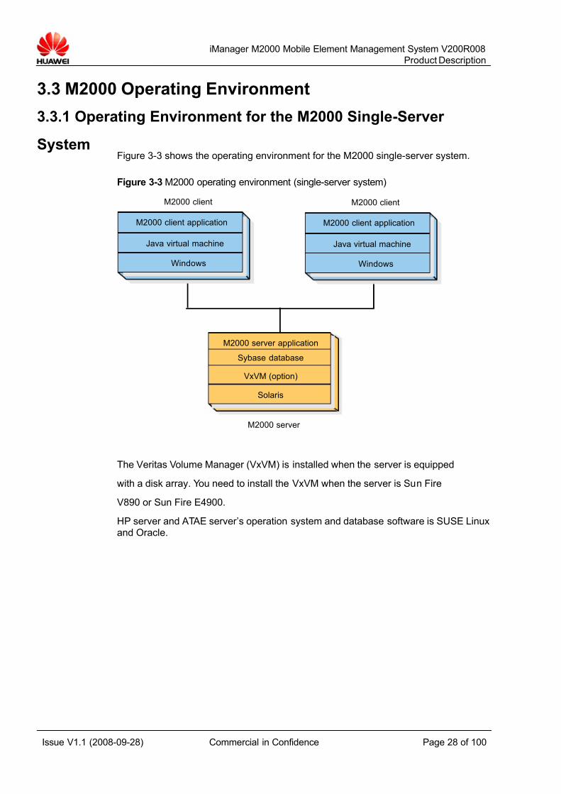
3.3 M2000 Operating Environment
3.3.1 Operating Environment for the M2000 Single-Server
SystemFigure 3-3 shows the operating environment for the M2000 single-server system.
Figure 3-3 M2000 operating environment (single-server system)
M2000 server
Sybase database
M2000 server application
Solaris
VxVM (option)
M2000 client application
Java virtual machine
Windows
M2000 client
M2000 client application
Java virtual machine
Windows
M2000 client
The Veritas Volume Manager (VxVM) is installed when the server is equipped
with a disk array. You need to install the VxVM when the server is Sun Fire
V890 or Sun Fire E4900.
HP server and ATAE server’s operation system and database software is SUSE Linuxand Oracle.
7/14/2019 754002000200008 Oc
http://slidepdf.com/reader/full/754002000200008-oc 29/100
iManager M2000 Mobile Element Management System V200R008
Product Description
Issue V1.1 (2008-09-28) Commercial in Confidence Page 29 of 100
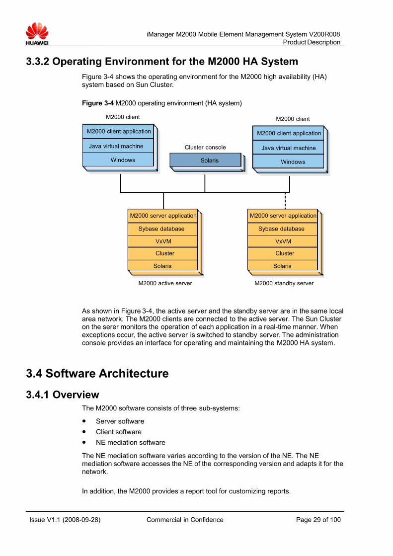
3.3.2 Operating Environment for the M2000 HA System
Figure 3-4 shows the operating environment for the M2000 high availability (HA)system based on Sun Cluster.
Figure 3-4 M2000 operating environment (HA system)
M2000 client application
Java virtual machine
Windows
M2000 client
M2000 client application
Java virtual machine
Windows
M2000 client
M2000 active server M2000 standby server
Cluster console
Solaris
Sybase database
M2000 server application
Solaris
VxVM
Cluster
Sybase database
M2000 server application
Solaris
VxVM
Cluster
As shown in Figure 3-4, the active server and the standby server are in the same localarea network. The M2000 clients are connected to the active server. The Sun Cluster on the serer monitors the operation of each application in a real-time manner. Whenexceptions occur, the active server is switched to standby server. The administrationconsole provides an interface for operating and maintaining the M2000 HA system.
3.4 Software Architecture
3.4.1 OverviewThe M2000 software consists of three sub-systems:
z Server software
z Client software
z NE mediation software
The NE mediation software varies according to the version of the NE. The NEmediation software accesses the NE of the corresponding version and adapts it for thenetwork.
In addition, the M2000 provides a report tool for customizing reports.
7/14/2019 754002000200008 Oc
http://slidepdf.com/reader/full/754002000200008-oc 30/100
iManager M2000 Mobile Element Management System V200R008
Product Description
Issue V1.1 (2008-09-28) Commercial in Confidence Page 30 of 100
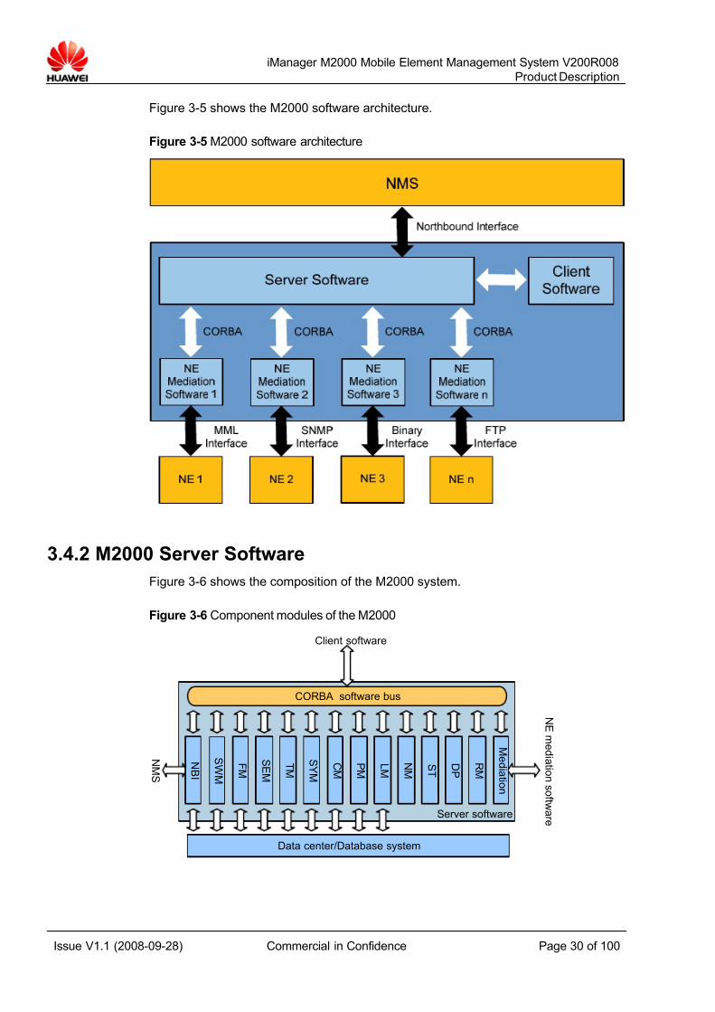
Figure 3-5 shows the M2000 software architecture.
Figure 3-5 M2000 software architecture
3.4.2 M2000 Server Software
Figure 3-6 shows the composition of the M2000 system.
Figure 3-6 Component modules of the M2000
CORBA software bus
Data center/Database system
NM S
NE m e d i a t i on s of t w ar e
Client software
Server software
NB I
S WM
F M
S E M
T M
S Y M
C M
P M
L M
S T
DP
RM
M e d i a t i on
NM

7/14/2019 754002000200008 Oc
http://slidepdf.com/reader/full/754002000200008-oc 31/100
iManager M2000 Mobile Element Management System V200R008
Product Description
Issue V1.1 (2008-09-28) Commercial in Confidence Page 31 of 100
The M2000 server software consists of 15 modules. Through the CORBA softwarebus, these modules communicate with each other and with the correspondingmodules of the M2000 client software.
The M2000 server provides the interface for the NMS through the NM interface
module. It provides interfaces for the mediation software of various NEs through themediation common module. Some modules access the M2000 server databasethrough the database interface.
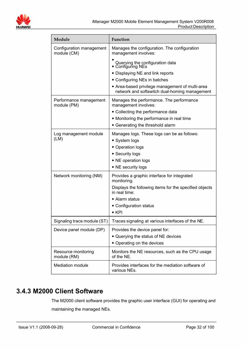
Table 3-13 describes these modules and their functions.
Table 3-13 Modules of the M2000 server software and their functions
Module Function
NMS interface module(NBI)
Provides the northbound interface for the NMS
Software managementmodule (SWM)
Manages the software. The software managementinvolves:
z Querying the software version
z Downloading software patches
z Activating/Deactivating the software
Fault management module(FM)
Manages alarms. The fault management involves:
z Collecting alarms
z Querying alarms
z Processing alarms
Security managementmodule (SEM)
Manages the system security. The system securityinvolves:
z Managing user authorities
z Managing user groups
Topology managementmodule (TM)
Manages the topology. The topology managementinvolves:
z Managing topology objects
z Managing the topology view
System managementmodule (SYM)
Manages the system. The system managementinvolves:
z Managing the system license
z Initializing the system
z Installing and uninstalling the software
z Managing scheduled system tasks
7/14/2019 754002000200008 Oc
http://slidepdf.com/reader/full/754002000200008-oc 32/100
iManager M2000 Mobile Element Management System V200R008
Product Description
Issue V1.1 (2008-09-28) Commercial in Confidence Page 32 of 100
Module Function
Configuration managementmodule (CM)
Manages the configuration. The configurationmanagement involves:
z
Querying the configuration dataz Configuring NEs
z Displaying NE and link reports
z Configuring NEs in batches
z Area-based privilege management of multi-areanetwork and softswitch dual-homing management
Performance managementmodule (PM)
Manages the performance. The performancemanagement involves:
z Collecting the performance data
z Monitoring the performance in real time
z Generating the threshold alarm
Log management module(LM)
Manages logs. These logs can be as follows:
z System logs
z Operation logs
z Security logs
z NE operation logs
z NE security logs
Network monitoring (NM) Provides a graphic interface for integratedmonitoring.
Displays the following items for the specified objectsin real time:
z Alarm status
z Configuration status
z KPI
Signaling trace module (ST) Traces signaling at various interfaces of the NE.
Device panel module (DP) Provides the device panel for:
z Querying the status of NE devices
z Operating on the devices
Resource monitoringmodule (RM)
Monitors the NE resources, such as the CPU usageof the NE.
Mediation module Provides interfaces for the mediation software of various NEs.
3.4.3 M2000 Client Software
The M2000 client software provides the graphic user interface (GUI) for operating and
maintaining the managed NEs.
7/14/2019 754002000200008 Oc
http://slidepdf.com/reader/full/754002000200008-oc 33/100
iManager M2000 Mobile Element Management System V200R008
Product Description
Issue V1.1 (2008-09-28) Commercial in Confidence Page 33 of 100
Each module of the M2000 server software, except the mediation common moduleand the NMS interface module, corresponds to a module on the GUI.
You can start the report tool client, Configuration Management Express (CME), andthe NE LMT directly from the M2000 client.
3.4.4 NE Mediation Software
The NE mediation software provides the interface files and mediation files the NEneeds to access the M2000 system. Each piece of mediation software corresponds toone or more NE versions.
3.5 Interfaces
3.5.1 Northbound Interfaces
The M2000 supports the following Itf-N network management interfaces:
z Itf-N interface
The Itf-N interface is based on CORBA interface protocols and is in compliancewith 3GPP R6 protocols. Through the Itf-N interface, the NMS can manageM2000 alarms, set performance measurement tasks, and query M2000configuration data.
z CORBA security interfaceThrough the CORBA interface, the NMS manages M2000 users and user rights,such as the rights for creating users, maintaining user information, and queryingand modifying user attributes.
z File interface
The NMS retrieves from the M2000 the alarm, performance, and configurationdata saved to TXT files. The performance file interface can be connected toseveral NMSs and has the function of northbound user management. Theperformance files can be filtered by operator.
z Alarm streaming interface
The M2000 sends the processed NE alarms in the form of character stream tothe NMS.
z SNMP interface
The M2000 sends the processed alarms in the form of text to the NMS through
the SNMP alarm interface. The SNMP interface supports the SNMPv1, SNMPv2,and SNMPv3 protocols.
z MML transparent transmission interface
The MML transparent transmission interface serves as a proxy for transferringMML commands between the NMS and NEs. Through this interface, the NMScan operate and maintain the associated NEs using MML commands.
3.5.2 Southbound Interfaces
The M2000 manages mobile NEs through the Human Machine Language (MML)interfaces or binary interfaces, and manages the IP devices using the Simple NetworkManagement Protocol (SNMP).
7/14/2019 754002000200008 Oc
http://slidepdf.com/reader/full/754002000200008-oc 34/100
iManager M2000 Mobile Element Management System V200R008
Product Description
Issue V1.1 (2008-09-28) Commercial in Confidence Page 34 of 100
In addition, the files such as NE log files and performance result files are transportedusing the FTP protocol between the M2000 and managed NEs.
3.5.3 Internal Interfaces
The server software, client software and mediation software in the M2000 systemcommunicate with each other through the CORBA interface.
7/14/2019 754002000200008 Oc
http://slidepdf.com/reader/full/754002000200008-oc 35/100
iManager M2000 Mobile Element Management System V200R008
Product Description
Issue V1.1 (2008-09-28) Commercial in Confidence Page 35 of 100
4 Services and Functions
4.1 Topology Management
4.1.1 Topology Object Management
Topology object refers to the NE, subnet, or link on a topology map.
Topology object management provides the following functions:
z Creating and deleting topology objects
Bulk creation and deletion are also supported.
z Modifying the attributes of a topology object
You can modify the basic attributes or position of a topology object on the map.
z Finding the specified NE
You can search by NE name, software version, vendor, or IP address. The M2000supports both precise search and fuzzy search.
z Customizing the topology map
You can conduct the settings to display or hide NEs or links of some type.
z Automatically displaying physical links between NEs and discovering basestations
4.1.2 Topology Object Viewing
On a topology map, you can view the following information:
z Detailed information of an NE
z Connection status of an NE
In case an NE is disconnected, the M2000 automatically originates thereconnection attempts.
z Links between NEs
z Alarms of NEs and links
z KPI of NEs and links
7/14/2019 754002000200008 Oc
http://slidepdf.com/reader/full/754002000200008-oc 36/100
iManager M2000 Mobile Element Management System V200R008
Product Description
Issue V1.1 (2008-09-28) Commercial in Confidence Page 36 of 100
4.1.3 Topology Map Management
The topology map can display NEs and links as hierarchical subnets. Each subnetcan use different topology map. The topology map can flags the accurate location of an NE.
4.1.4 Shortcut Operation Access
The M2000 offers shortcut operation accesses on the topology map, which facilitatequerying the following information:
z Configuration information of NEs and links
z Alarm information
z Performance measurement results
After the client is installed with the corresponding LMT software version, you can startthe LMT on the topology map.
4.2 Configuration Management
4.2.1 Configuration Data Synchronization
The M2000 saves the configuration data of all NEs and synchronizes the data in realtime.
The configuration data can be synchronized in the following three modes:
z Automatic synchronization
Changes in the NE configuration are automatically reported to the M2000. Thenthe system updates the existing configuration data on the M2000.
z Manual synchronization
You can synchronize the configuration data on the M2000 client manually. Thenthe system acquires the latest configuration data from NEs and updates theexisting data on the M2000.
z Periodic synchronization
The M2000 system synchronizes the configuration data periodically. Then thesystem acquires the latest configuration data from NEs and updates the existingdata on the M2000.
4.2.2 Configuration Data Query
Through this function, the M2000 client allows you to:
z Query NE configuration data on the client and view the queried results in reports.
z Refresh the configuration data and search for configuration objects.
For a large number of configuration data, the system segments the data and displaysthem in different tabs on the client.
4.2.3 Configuration Data Export
The M2000 provides the export of the following two types:
7/14/2019 754002000200008 Oc
http://slidepdf.com/reader/full/754002000200008-oc 37/100
iManager M2000 Mobile Element Management System V200R008
Product Description
Issue V1.1 (2008-09-28) Commercial in Confidence Page 37 of 100
z Manual export
z Scheduled export
You can export NE configuration data to .xml files or .csv files to the specified directoryof the server.
Scheduled export supports only XML format. Manual export supports both XML andCSV formats.
4.3 Centralized Fault Management
4.3.1 Real-Time Alarm Monitoring
On the M2000, you can monitor alarms of all NEs in the network. Thus you can knowthe alarm severity, alarm type, and causes, and handle fault alarms in time.
The M2000 provides the following alarm notification modes:
z Displaying alarms of different severities and statuses in custom colors on theinterface, such as topology view and alarm browse window.
The M2000 also highlights the fault alarms that have not been handled for a longtime.
z Displaying the total of alarms of each severity on the alarm board, and alertingyou by sounds and blinking icons.
z Providing remote alarm notification by E-mail or SMS.
You can set the conditions of alarm forwarding.
z Displaying the current alarm status using the custom sound when a sound box isconnected to the client.
z Providing audible and visual alarms when an alarm box is connected to the client.
z Printing the alarm information when a printer is connected to the client.
After alarms are handled, the M2000 automatically changes the correspondingstatuses to be cleared. For the alarm which is handled while the status is not changed,you can manually change the status to be cleared.
On the M2000 client, you can check whether the statuses of the specified alarm areconsistent on the NE and the M2000. If the statuses are different, the M2000 updatesthe alarm status to keep the consistency with the NE.
4.3.2 Alarm Data ManagementThe M2000 database stores all NE alarms in the network. You can export the alarmdata when required.
To ensure the correctness of the data in the database, the M2000 synchronize alarms.
The M2000 supports automatic, manual, and scheduled alarm synchronization. Thethree types of synchronization are described as follows:
z Automatic alarm synchronization
NEs automatically report the changed alarms to the M2000. Then the M2000updates the alarm database.
z Manual alarm synchronization
7/14/2019 754002000200008 Oc
http://slidepdf.com/reader/full/754002000200008-oc 38/100
iManager M2000 Mobile Element Management System V200R008
Product Description
Issue V1.1 (2008-09-28) Commercial in Confidence Page 38 of 100
You can synchronize alarms manually on the M2000 client. Then the M2000updates the alarm database.
z Scheduled alarm synchronization
The M2000 synchronizes alarms at the scheduled time every day. Then the
M2000 updates the alarm database.
4.3.3 Alarm Query and Statistics
For this function, the M2000 enables you to:
z Query the generated alarms of all NEs, and know the handling situation. Savecommon query conditions to query templates.
z Set conditions to collect the statistics of alarm situations, alarm severities, andNE type.
z Print the result of alarm query and statistics.
4.3.4 Alarm Assisting HandlingThe M2000 offers alarm acknowledgement mechanism, which allows you to indicatewhether the current alarm is noticed and handled. You can acknowledge or unacknowledge alarms manually, or set acknowledge alarms automatically.
You can add comments for each alarm. For the convenience of subsequentoperations, the alarm remark can tell history operations, operator, operating time, andadditional information. You can record your alarm handling experiences, such as faultlocation and handling suggestions, in the alarm knowledge library. This facilitatestroubleshooting and sharing maintenance experiences.
You can set conditions for the M2000 to analyze correlation, redefine alarm severity,
and shield alarms of specified NEs. In this case, you can focus on key alarms, locatealarms promptly and correctly, and maintain the network in various scenarios.
4.4 Centralized Performance Management
4.4.1 NE Performance Measurement Setting
You can set the method for measuring NE performance based on requirements.
The settings for NE performance measurement include:
z Counters
z Objects
z Intervals
Performance counters of an NE fall into two categories: common counters andextended counters. The M2000 collects common data about the common countersautomatically. Based on the common counters, you can view and set the extendedcounters for collection on the M2000 client.
Performance objects of NEs fall into the following three categories:
z Class 1 performance objects
7/14/2019 754002000200008 Oc
http://slidepdf.com/reader/full/754002000200008-oc 39/100
iManager M2000 Mobile Element Management System V200R008
Product Description
Issue V1.1 (2008-09-28) Commercial in Confidence Page 39 of 100
The M2000 collects counter information for these objects automatically You canchoose not to measure them.
z Class 2 performance objects
You must specify the objects through the M2000 client to collect counter
information.z Class 3 performance objects
You must specify the objects and enter required parameters for the M2000 tocollect counter information.
Performance measurement intervals can be 5 minutes, 15 minutes, 30 minutes, 60minutes, and 24 hours. Some measurement counters do not support the intervals of 5minutes and 15 minutes.
4.4.2 Real-Time Monitoring of Performance Results
You can specify an object or a counter for real-time monitoring. In addition, you can
monitor an object on multiple clients.
The M2000 allows you to use a custom real-time monitoring template to start amonitoring task. You can also modify or delete a real-time monitoring template. TheM2000 displays real-time monitoring result through tables or graphics. You can filter results and define display effect by setting conditions.
4.4.3 Performance Result Query
In one measurement interval, the value of a measurement counter is a measurementresult of an object.
This function enables you to:
z Set object, counter, and time to query the performance result.
z Set the query time period to the busy hour counters to query performance resultsof the busiest hour of a day.
z Query performance results through default or custom performance result querytemplates.
z Customize, delete, or modify custom performance result query templates.
The M2000 displays the queried performance result in tables, linear chart or bar chart.You can also print the queried results. For the result table, you can specify theconditions to sort the results. For the linear chart, you can specify to the display theresult of multiple counters for one object, or the result of one counter for multiple
objects.
You can check whether the performance results are reliable, and whether missingperformance data exists. If there is missing performance data, trigger the performancedata synchronization.
You can subscribe performance results. In this case, you can browse the performanceresults in real time.
4.4.4 Performance Data Management
The M2000 database stores the performance data of all NEs. You can export theperformance data .xml files or .csv files and save them on the server.
7/14/2019 754002000200008 Oc
http://slidepdf.com/reader/full/754002000200008-oc 40/100
iManager M2000 Mobile Element Management System V200R008
Product Description
Issue V1.1 (2008-09-28) Commercial in Confidence Page 40 of 100
The M2000 provides two types of data export:
z Export of latest data
Export the performance data collected in the recent period to files. This can helpthe analysis for other systems and users.
z Export of oldest data
Export the performance data that exceeds the validity period to files. The recordsin the database are deleted. This protects the database.
The M2000 exports data through automatic and manual synchronization, so that theperformance data stored on the EMS and the NEs are consistent.
4.4.5 Performance Alarm
The M2000 allows you to set the threshold alarm for a specified or customperformance measurement counter. When the value of the counter exceeds thepreset threshold, the M2000 triggers a fault alarm at the corresponding level based on
preset conditions to alert you.
The M2000 allows you to set a combination of multiple conditions as the triggeringcondition of a threshold alarm. The set alarm levels support dynamic change. If a typeof alarm is raised for several weeks in succession, the M2000 can upgrade the level of this alarm. According to the actual requirements, you can set that an alarm is raisedonly after the alarm triggering condition is met for several weeks in succession.
The M2000 allows you to set threshold alarms for object groups. The counters in theobject group are summarized to set the threshold. When the value of the counter exceeds the preset threshold, the M2000 triggers a threshold alarm.
The M2000 allows you to query by threshold. It also allows you to set threshold alarms
by tasks. You can set the time for activating and suspending of threshold tasks. Alternatively, you can manually activate and suspend threshold tasks.
4.4.6 Custom Counters
Custom counter is a new measurement counter which is the result of adding,subtracting, multiplying, and dividing multiple performance counters of the NE. Whenreceiving performance results from the NE, the M2000 calculates the value of thecustom counter according to the user-defined formula. Then you can query andprocess the results in future.
For custom counters, the M2000 allows you to:
z Customize, modify, and delete the custom counter.z Export or import custom counters to share and back up them.
4.4.7 Performance Report
The M2000 allows you to retrieve the KPI data of the network and summarizing thedata on the time and object basis. You can query and browse the summary data.Compared with the original performance data, the summary data enjoys the longer storage period.
The performance report has the following features:
z Policy on discovering multiple busy hours
7/14/2019 754002000200008 Oc
http://slidepdf.com/reader/full/754002000200008-oc 41/100
iManager M2000 Mobile Element Management System V200R008
Product Description
Issue V1.1 (2008-09-28) Commercial in Confidence Page 41 of 100
z Custom measurement counters
z Predefined reports to provide basis analysis methods
z Custom reports
z Long-term storage for special and crucial data
z Comparison report to compare the data at two time points
4.5 Centralized Security Management
4.5.1 User and User Group Management
The M2000 user information consists of the following items:
z User account: the user name for a user to log in to the M200.
z Password: the password used by the user to access the M2000.
z Login time: a valid time period for a user to log in to the M2000.
z Allowable terminals: defines through which IP addresses can users log in to theM2000.
z User group: refers to those groups that each user belongs to which they have therelated operation and maintenance (O&M) authority.
You can create, modify, and delete a user group or user. The M2000 automaticallycreates the user account admin and the user group Administrators after theinstallation of the system. The user admin belongs to Administrators and has all theadministration, operation, and maintenance authorities.
4.5.2 User Authority ManagementThe M2000 assigns different operation authorities for different O&M tasks. Only theusers having the O&M authorities can perform the related operations.
The M2000 divides all operations into two types based on the association with NEs.
z For the operations not associated with NEs, the M2000 assigns OMC authorities.
z For the operations associated with NEs, the M2000 assigns NE authorities.
You can preset NE authorities. In other words, you can set the authorities for a type of NE. Once a new NE of this type is created on the M2000, you are automaticallygranted the preset authorities.
The M2000 can assign operation authorities to user groups, thus all users in the grouphave these authorities.
The M2000 can also directly assign operation authorities to a user.
The authorities of a user consist of two parts:
z Public authority: refers to the authority that is inherited from the user group.
z Private authority: refers to the authority that is directly allocated to the user.
7/14/2019 754002000200008 Oc
http://slidepdf.com/reader/full/754002000200008-oc 42/100
iManager M2000 Mobile Element Management System V200R008
Product Description
Issue V1.1 (2008-09-28) Commercial in Confidence Page 42 of 100
4.5.3 User Monitoring
On the M2000 client, you can monitor online users in real time. Through themonitoring interface, the M2000 displays the information such as user name,operation, executing time, result, and terminal.
In addition, you can force the specified user to exit to protect the system against illegaloperations.
The system also automatically monitors user logins. If the time of consecutive failedlogin attempts exceeds the limit, the user is locked automatically.
4.5.4 Terminal Locking
The system locks a terminal that has been idle for a certain period. You must log inagain to prevent illegal users. You can also lock the terminal manually to avoid illegaloperations.
After the administrator or current user enters the password the terminal is unlocked.
4.5.5 Security Policy Setting
The M2000 provides a flexible security policy setting function to meet therequirements of different users.
The policies that can be set include:
z Minimum length of user password
z Minimum number of special characters contained in a password
z Minimum number of numeric letters contained in a password
z Minimum number of letters contained in a password
z Validity period for a password (in days)
z Maximum interval for modifying a password
z Number of non-duplicate historical passwords
z Maximum number of login attempts
z Legal prescription after the login of a valid user
z Duration for locking the user account after maximum of login attempts (inminutes)
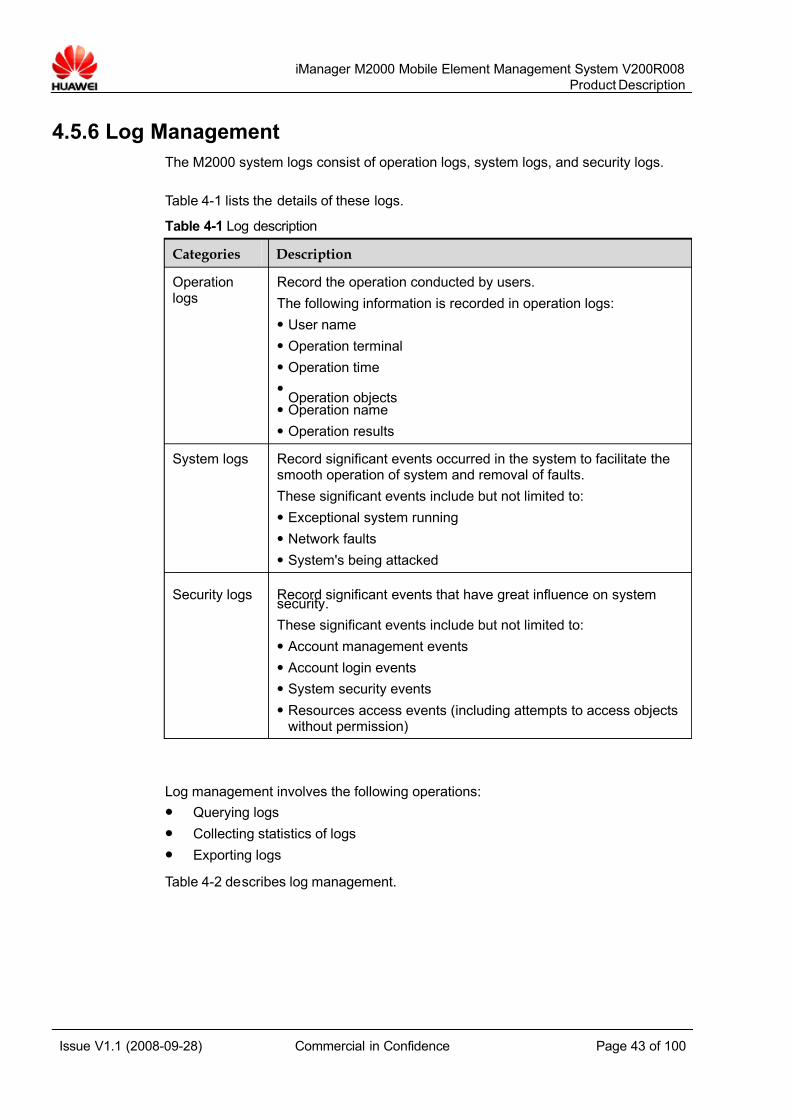
7/14/2019 754002000200008 Oc
http://slidepdf.com/reader/full/754002000200008-oc 43/100
iManager M2000 Mobile Element Management System V200R008
Product Description
Issue V1.1 (2008-09-28) Commercial in Confidence Page 43 of 100
4.5.6 Log Management
The M2000 system logs consist of operation logs, system logs, and security logs.
Table 4-1 lists the details of these logs.
Table 4-1 Log description
Categories Description
Operationlogs
Record the operation conducted by users.
The following information is recorded in operation logs:
z User name
z Operation terminal
z Operation time
z Operation objectsz Operation name
z Operation results
System logs Record significant events occurred in the system to facilitate thesmooth operation of system and removal of faults.
These significant events include but not limited to:
z Exceptional system running
z Network faults
z System's being attacked
Security logs Record significant events that have great influence on systemsecurity.
These significant events include but not limited to:
z Account management events
z Account login events
z System security events
z Resources access events (including attempts to access objectswithout permission)
Log management involves the following operations:
z Querying logs
z Collecting statistics of logs
z Exporting logs
Table 4-2 describes log management.
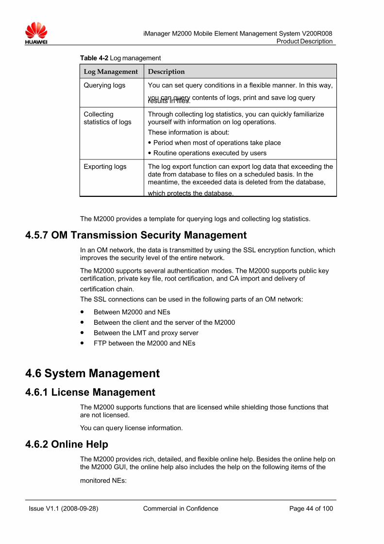
7/14/2019 754002000200008 Oc
http://slidepdf.com/reader/full/754002000200008-oc 44/100
iManager M2000 Mobile Element Management System V200R008
Product Description
Issue V1.1 (2008-09-28) Commercial in Confidence Page 44 of 100
Table 4-2 Log management
Log Management Description
Querying logs You can set query conditions in a flexible manner. In this way,
you can query contents of logs, print and save log queryresults in files.
Collectingstatistics of logs
Through collecting log statistics, you can quickly familiarizeyourself with information on log operations.
These information is about:
z Period when most of operations take place
z Routine operations executed by users
Exporting logs The log export function can export log data that exceeding thedate from database to files on a scheduled basis. In themeantime, the exceeded data is deleted from the database,
which protects the database.
The M2000 provides a template for querying logs and collecting log statistics.
4.5.7 OM Transmission Security Management
In an OM network, the data is transmitted by using the SSL encryption function, whichimproves the security level of the entire network.
The M2000 supports several authentication modes. The M2000 supports public keycertification, private key file, root certification, and CA import and delivery of
certification chain.
The SSL connections can be used in the following parts of an OM network:
z Between M2000 and NEs
z Between the client and the server of the M2000
z Between the LMT and proxy server
z FTP between the M2000 and NEs
4.6 System Management
4.6.1 License Management
The M2000 supports functions that are licensed while shielding those functions thatare not licensed.
You can query license information.
4.6.2 Online Help
The M2000 provides rich, detailed, and flexible online help. Besides the online help onthe M2000 GUI, the online help also includes the help on the following items of the
monitored NEs:

7/14/2019 754002000200008 Oc
http://slidepdf.com/reader/full/754002000200008-oc 45/100
iManager M2000 Mobile Element Management System V200R008
Product Description
Issue V1.1 (2008-09-28) Commercial in Confidence Page 45 of 100
z MML command
z Performance indicators
z Alarm handling
The M2000 GUI is a context-sensitive help. That is, you can invoke the followinginformation from the online help:
z Specific pages for operation guidance
z Introductory pages for MML commands
z Pages for alarm handling
4.6.3 System Status Monitoring
The system status monitoring enables you to check the following items:
z Status of each service session
z
Occupancy of resources (including CPU, memory, hard disk, and database)z Applications installed on the M2000 server
4.6.4 Centralized Scheduled Task Monitoring
Using a unified interface, the task management manages and schedules all thescheduled tasks in an integrated manner.
You can execute the following operations on the scheduled tasks:
z Creating
z Deleting
z
Modifyingz Suspending
z Resuming
Task-related parameters can also be configured.
You can view the following information on tasks on the task management interface:
z Status
z Results
z Progress
The system scheduled tasks are of the following categories:
z Database management
z Data synchronization
z Data export
z Backup
z Script
z Scheduled software download
z CME configuration
The scheduled tasks can be categorized as follows:
z One-time tasks
7/14/2019 754002000200008 Oc
http://slidepdf.com/reader/full/754002000200008-oc 46/100
iManager M2000 Mobile Element Management System V200R008
Product Description
Issue V1.1 (2008-09-28) Commercial in Confidence Page 46 of 100
Refer to a task that is executed only once at some time.
z Periodic tasks
Refer to a task that is executed on a periodic basis.
4.6.5 Individual SettingThe M2000 allows you to set the interface based on personal preference. Theindividual settings can be shared among different clients.
The following settings are available:
z Common setting: defines the style in which the client is displayed.
z Context setting: switches to the setting of the last time when certain function isenabled.
4.6.6 System Data Backup and Restore
The system data can be backed up automatically or manually. The data that is backedup can be recovered manually only.
In addition, the system supports the Veritas-based system back up solution from thethird party. The solution can back up the whole system.
The backup of the whole system involves the backup of:
z Operating system
z Database
z M2000 applications
z Related data
You can execute backup and restore operations through the Veritas interface. Automatic and manual backup are supported on the M2000.
4.6.7 System Uninstalling
When the M2000 is uninstalled, the system recovers to the status before installation.
4.6.8 Client Remote Access
z The M2000 clients communicate with the M2000 server or servers using TCP/IP.Thus, the clients can remotely access the M2000 server in many ways:
z
The common access modes is to use Internet or VPN. The client is connected toserver directly in case the IP address of the server can be accessed. In such asituation, you need to set firewalls to safeguard the network.
4.6.9 Citrix-Based Client Access
In the Citrix solution, the Citrix server and Citrix clients are included. All applicationsrun on the Citrix server or on Citrix server groups, while the Citrix client provides onlyan interface for operating on these applications or displaying the operation results.
The Citrix clients communicate with Citrix server or server groups using IndependentComputing Architecture (ICA). When applications are running, only the followinginformation is transferred between Citrix server (server groups) and Citrix clients:
7/14/2019 754002000200008 Oc
http://slidepdf.com/reader/full/754002000200008-oc 47/100
iManager M2000 Mobile Element Management System V200R008
Product Description
Issue V1.1 (2008-09-28) Commercial in Confidence Page 47 of 100
z Screen refreshment
z Keyboard pressing
z Mouse movement
In the M2000 Citrix solution, the Citrix server or Citrix server group is deployed in thenetwork where the M2000 server is located. You can execute operations on theM2000 client applications that are running on Citrix server or Citrix server groupthrough the Citrix clients. In this way, you conduct maintenance on the network under consideration.
When using Citrix solution, you only need to install Citrix client applications; thuslowering the requirements for user access. In addition, the requirement for bandwidthbetween Citrix server and clients is relatively low, which enables you to select accessdevices and network flexibly.
The Citrix solution significantly improves the security control for terminal access.
4.7 Time Management for the Entire Network
4.7.1 Time Zone Management
The M2000 can deal with time transient caused by the fact that the M2000 system islocated in a time zone different from where managed NEs are located.
According to the demands, you can set to display on the M2000 client:
z Time in the time zone where the specified NE is located
z Time in the time zone where the M2000 server is located
4.7.2 DST Supported
The M2000 system supports the daylight saving time (DST) and handles the timetransient brought about by DST. Not only the operation time but the DST-relatedinformation is displayed on the M2000 client.
4.7.3 Time Synchronization for the Entire Network
According to the NTP or SNTP, the M2000 guarantees the consistency in time for allthe NEs in the network. The reference source for the NTP can be external time server.
4.8 UTRAN Specified Functions
4.8.1 NE Software Management
The M2000 implements centralized management on software and their patches.
The software versions and their patches for NEs can be transmitted among M2000clients, file server (usually the M2000 server), and NEs. In this way, the software andtheir patches of a version for all NEs are saved and managed on the M2000 server.
You can perform the following operations on the RNC:
7/14/2019 754002000200008 Oc
http://slidepdf.com/reader/full/754002000200008-oc 48/100
iManager M2000 Mobile Element Management System V200R008
Product Description
Issue V1.1 (2008-09-28) Commercial in Confidence Page 48 of 100
z Loading
z Rolling back
z Activating patches
z Acknowledging
z Unacknowledging
z Deleting
You can execute the following operations on the NodeB and TGW:
z Remotely upgrading NodeBs and TGWs by task in batches
z Loading software based on actual configuration of the NodeB
4.8.2 NodeB License Management
The M2000 manages Node licenses.
The NodeB license management involves:
z Viewing license files
z Viewing license information on the NodeB
z Synchronizing license information
z Issuing license information
4.8.3 RAN Sharing
The M2000 supports the sharing of RAN between different operators.
The RAN sharing provides the following functions:
z Configuring information of different operators supported by the RNC. Theinformation is as follows:
− Operator name
− ID
− MCC
− MNCWhen configuring the cell data, specify an operator ID for the cell. Usingthe operator ID, you can check to which operator the cell belongs.
z The M2000 supports the download of license to NEs and the activation of licenseon NEs. For the NodeB, the user first configures control information in the licensefile. The M2000 issues the configured control information to NEs managed. Then,
the NEs conduct validity check on control information.z The northbound interfaces control the data of cells using the operator ID. In this
way, each operator can only manage the data of cells under control. The M2000supports the authentication policy for user account and password when theNMSs of different operators are connected. At present, the northbound interfacesthat support the RAN sharing management are CORBA alarm interface and fileperformance interface.
4.8.4 FTP Encrypted Transmission Based on SSL
The M2000 supports the transmission in FTP mode based on SSL. Tailored to thedemand of carriers for the safety of FTP transmission, the FTP encrypted
transmission improves the security of data transmission.
7/14/2019 754002000200008 Oc
http://slidepdf.com/reader/full/754002000200008-oc 49/100
iManager M2000 Mobile Element Management System V200R008
Product Description
Issue V1.1 (2008-09-28) Commercial in Confidence Page 49 of 100
A safety FTP transmission channel is established between M2000 server and NEs totransfer the M2000 data in encrypted mode. The supported SSL protocol versions areSSL V2.0 and SSL V3.0.
4.8.5 UTRAN IP NetworkingThe M2000 supports automatic NodeB discover and automatic IP address allocationin the IP networking topology.
The M2000 supports the automatic switchover of dual IP addresses for the NodeB toguarantee the system reliability.
4.8.6 NE Data Backup
The M2000 backs up the data running on NEs to the M2000 server.
The backup data consists of:
z Configuration dataz Performance data
z Alarm data
z Log data
You can back up the data in the following modes:
z In periodic mode
Backs up the data of all NEs
z In manual mode
Backs up the data of the specified NEs
4.8.7 Custom NE Alarms
You can set alarm severity of NEs on the M2000. The NE reports alarms based on themodified alarm severity. In addition, you can shield some specified alarms of NEs. TheNE does not report the shielded alarms.
Some interfaces for external alarms are provided for the NodeB. Based on actualon-site requirements, you can define alarms for NodeB peripherals on the M2000 tomonitor the performance of the site where the NodeB is located.
These peripherals include:
z
Power equipmentz Lightning protection equipment
z Air conditioner
z Environment monitoring equipment
The site performance refers to:
z Operating status of the NodeB
z Operating status of the peripherals of the NodeB
z Environment status of the site where the NodeB is located
You can define the following attributes of alarms on the M2000 GUI:
z ID

7/14/2019 754002000200008 Oc
http://slidepdf.com/reader/full/754002000200008-oc 50/100
iManager M2000 Mobile Element Management System V200R008
Product Description
Issue V1.1 (2008-09-28) Commercial in Confidence Page 50 of 100
z Name
z Severity
4.8.8 Real-Time Network Monitoring
With the real-time network monitoring, you can:
z Monitor the status of key resources in the network.
z Detect network faults in time.
z Ensure the system security during important periods, such as holidays andimportant conferences.
This function obtains values of KPIs from NEs in real time and displays them on theclient in charts. This helps you know the current network communication status.
In addition, this function sets ranges for the counter values. The M2000 generates analarm when the value exceeds the range and informs users to handle the alarm
immediately.
4.8.9 Centralized User Management
The M2000 manages the O&M users in an integrated manner. That is, you can createusers on the M2000 and set for the established users the operating authorities(including the authority on the M2000 and NEs). After the setting, you can log in to theM2000 or to the associated LMT as the established user and execute operations.
When a user logs in to the M2000 client or to the LMT, the M2000 verifies the accessauthority of the user. The M2000 allows only valid users to log in and use theoperation and maintenance system (including the M2000 and the associated LMT of NEs).
When a user executes operations on the M2000 client or on the LMT, the M2000 alsoverifies their operating authority to prevent any authority abuse.
To manage users in an integrated manner, you also need to define for establishedusers the operating authority on specified MML groups of specified NEs. To achievethis, you can set for users operating authorities on:
z Some command groups of the specified NE
z MML command groups of an NE of a category
In the latter method, the established user has the operating authority on MMLcommand groups of all the NEs of this category.
The M2000 monitors the users' operations on the LMT in real time. On the monitoringinterface, the following information is displayed:
z User name
z Operation
z Time
z Result
z Operation terminal
During the monitoring, the M2000 can force users to exit from the LMT, whichprevents dangerous operation and safeguards the system.
7/14/2019 754002000200008 Oc
http://slidepdf.com/reader/full/754002000200008-oc 51/100
iManager M2000 Mobile Element Management System V200R008
Product Description
Issue V1.1 (2008-09-28) Commercial in Confidence Page 51 of 100
The M2000 collects the NE operation logs and security logs. You can query or collectstatistics of these logs on the M2000 GUI.
4.8.10 NE Configuration
You can deliver either one or several MML commands to the specified NEs throughthe MML interface on the M2000. In this way, you configure data of NEs. You can firstwrite the MML commands to be executed into a file, and then execute these MMLcommands through the MML interface.
The scheduled tasks based on MML commands can also be set.
The M2000 conducts NE configuration in batches through bulk configuration filesin .xml format. The bulk configuration involves the following operations onconfiguration data:
z Synchronizing
z Importing
z Exporting
z Checking syntax
z Pre-activating
z Activating
z Rolling back
Configuration services and related data comply with the 3GPP specifications.
4.8.11 NE Resources Monitoring
The M2000 can view and monitor the status of critical NE resources in real time.
The critical resources include:
z CPU
z Board
z Link
z Port
z Cell information
In addition, the M2000 can stimulate device panels of each NE.
Through graphic simulation panels, you can:
z Check hardware configurations of NE devices (including subracks, frames,boards, ports)
z Check hardware-related alarms of NE devices
z Maintenance the devices (such as resetting boards)
The M2000 also uses reports to offer detailed information on the following specifieditems:
z NE
z Link
z Resources
7/14/2019 754002000200008 Oc
http://slidepdf.com/reader/full/754002000200008-oc 52/100
iManager M2000 Mobile Element Management System V200R008
Product Description
Issue V1.1 (2008-09-28) Commercial in Confidence Page 52 of 100
4.8.12 Signaling Tracing
Signaling tracing is a key approach to locating faults. The M2000 traces user signalingmessages of NEs.
Create message tracing tasks on the M2000 client, and you can specify an NE user totrace its signaling messages in real time. In addition, you can save these signalingmessages into files for later query.
4.8.13 Inventory Management
The M2000 implements the centralized management on the information aboutphysical and logical assets of NEs.
The M2000 allows you to perform the following functions on the inventory data:
z Browsing
z Querying
z Maintaining
z Synchronizing
z Importing
z Exporting
4.8.14 OM Script Development
The M2000 provides a platform for script development. The script developmentincludes:
z Editing, debugging, and running scripts
z Executing tasks on a scheduled basis
You can use the script development platform to edit or run HSL to realize automaticroutine maintenance.
The HSL employs a group of HSL Foundation Component (HFC) to meet the routinemaintenance requirements:
z Simple statements
z Compound statements
z MML commands
z Database access
z Input/Output
z FTP
z File operation
z Time operation
4.8.15 NE Automatic Discovering
This function enables you to search for the NodeBs on the network by the RNCconfiguration and add the found NodeBs to M2000 management. Two search modesare available, that is, manual search and automatic search.

7/14/2019 754002000200008 Oc
http://slidepdf.com/reader/full/754002000200008-oc 53/100
iManager M2000 Mobile Element Management System V200R008
Product Description
Issue V1.1 (2008-09-28) Commercial in Confidence Page 53 of 100
This describes how to automatically search for NodeBs. The automatic searchingfunction helps you know information about the NodeBs under an RNC such as thetotal number of NodeBs under one RNC, the number of NodeBs that connect to theM2000, the number of NodeBs whose names are duplicate, and the number of NodeBs whose IP addresses are duplicate.
4.8.16 Network Integration Monitoring
The UTRAN network integration monitoring refers to the real-time monitoring ongraphic UTRAN objects. The monitoring checks the following information:
z Configuration status of each monitored objects
z Performance KPI
z Alarm information
The UTRAN network integration monitoring offers you a complete view on an interfaceto facilitate your check on the NE configurations.
The NE configuration information includes:
z Hardware configuration of the monitored NEs
z Interface configuration of the monitored NEs
In the UTRAN network integration monitoring, you can also obtain the alarm statisticsand performance analysis on configured objects.
For different NEs, the objects that can be monitored are different.
The following lists the monitored objects for different NEs:
z RNC
− NE alarm
− NE connection status
− KPI of the RNC
z NodeB
− NE alarm
− NE connection status
z Cell
− Cell alarm
− Cell status
− KPI of a cell
− Cell activation and deactivation
4.8.17 Graphic Configuration
The M2000 provides the CME as an integrated solution for NE configuration in severalRNSs in the UTRAN. The deployment of the CME varies according to the dataconfiguration.
z Independent of the M2000: The CME runs independently. It is not integrated withthe M2000 system. In addition, it does not connect with the current network inreal time.

7/14/2019 754002000200008 Oc
http://slidepdf.com/reader/full/754002000200008-oc 54/100
iManager M2000 Mobile Element Management System V200R008
Product Description
Issue V1.1 (2008-09-28) Commercial in Confidence Page 54 of 100
z Integrated with the M2000: The CME is integrated with the M2000 system andcan connect with the current network in real time.
The CME configure the device parameters, radio parameters, and transmissionparameters through the graphic interface. These parameters include the parameters
of:
z Cabinet, subrack, and board
z E1/T1 port, FE network port, and STM optical port
z GPS and electric adjustment antennaIub interface
z Iur interface
z Iu-CS interface
z Iu-PS interface
z Iu-BC interface
z Cells
z Neighbors
In addition to basic parameter configuration, the M2000 also provides:
z Base station/Cell configuration templates
z Multiple task-oriented configuration wizards
z Importing/Exporting planned data
z Rule check, consistency check, parameter comparison, and fast search of configuration data
z Consistency check and refresh of Iub interface data and wireless data of neighbor RNCs
The configuration data of NEs is classified into data of a current area and data of multiple planned areas. The data of the current area indicates the data that takeseffect on the current NEs. The planned area refers to the working area for the users tomodify the data.
After configuring data in planned areas, you can export the planned data as scripts for data configuration. The M2000 delivers these scripts to NEs immediately or on ascheduled basis. In this way, the planned data is converted into current data.
The M2000 has a configuration template for sites or cells and a task-orientedconfiguration wizard. In addition, the M2000 can import interface parameters of various types and networking planning parameters into the system, thus generating aplanned area.
The M2000 also conducts regular check on configuration data.
The regular check includes:
z Data correctness check
z Data redundancy check
z Data integrity check
z Comparison of radio algorithm parameters, including consistency check andrefreshment between Iub interface data and radio data between RNCs.
7/14/2019 754002000200008 Oc
http://slidepdf.com/reader/full/754002000200008-oc 55/100
iManager M2000 Mobile Element Management System V200R008
Product Description
Issue V1.1 (2008-09-28) Commercial in Confidence Page 55 of 100
4.8.18 Network Health Check
The network health check enables you to find the hidden problems of devices. Thus,severe accidents are avoided and proper operation of current devices is ensured.
z NE devices and status of the M2000 CheckDevice check enables you to check the status of the M2000 and NE devices suchas the RNC and NodeB. This check also exports check reports in .html format.
z NE alarm CheckBy using the alarm check function, the M2000 analyzes NE alarm trends,comparisons between alarms, TopN alarm features, alarm maintenance, andfault alarms. This check also exports check reports in .html format.
z Performance of the NE devices CheckPerformance check enables you to check the performance of the RNC. You cancollect statistics of the KPIs and export check reports in .html format.
4.9 GBSS Specified Functions
4.9.1 NE Software Management
The M2000 implements centralized management on software and their patches.
The software versions and their patches for NEs can be transmitted among M2000clients, file server (usually the M2000 server), and NEs. In this way, the software andtheir patches of a version for all NEs are saved and managed on the M2000 server.
You can perform the following operations on the BSC:
z Loading
z Rolling back
z Activating patches
z Acknowledging
z Unacknowledging
z Deleting
Besides the step-by-step upgrade, the M2000 provides the wizard for the upgrade of the BSC.
The M2000 allows you to remotely upgrade the BSC by task in batches.
4.9.2 Custom NE Alarms
You can set alarm severity of NEs on the M2000. The NE reports alarms based on themodified alarm severity. In addition, you can shield some specified alarms of NEs. TheNE does not report the shielded alarms.
Some interfaces for external alarms are provided for the BSC. Based on actual on-siterequirements, you can define alarms for BSC peripherals on the M2000 to monitor theperformance of the site where the BSC is located.
These peripherals include:
z
Power equipment

7/14/2019 754002000200008 Oc
http://slidepdf.com/reader/full/754002000200008-oc 56/100
iManager M2000 Mobile Element Management System V200R008
Product Description
Issue V1.1 (2008-09-28) Commercial in Confidence Page 56 of 100
z Lightning protection equipment
z Air conditioner
z Environment monitoring equipment
The site performance refers to:z Operating status of the BSC
z Operating status of the peripherals of the BSC
z Environment status of the site where the BSC is located
You can define the following attributes of alarms on the M2000:
z ID
z Name
z Severity
4.9.3 Centralized User ManagementThe M2000 manages the OM users in an integrated manner. That is, you can createusers on the M2000 and set for the established users the operating authorities(including the authority on the M2000 and NEs). After the setting, you can log in to theM2000 or to the associated LMT as the established user and execute operations.
When a user logs in to the M2000 client or to the LMT, the M2000 verifies the accessauthority of the user. The M2000 allows only valid users to log in and use theoperation and maintenance system (including the M2000 and the associated LMT of NEs).
When a user executes operations on the M2000 client or on the LMT, the M2000 also
verifies their operating authority to prevent any authority abuse.To manage users in an integrated manner, you also need to define for establishedusers the operating authority on specified MML groups of specified NEs. To achievethis, you can set for users operating authorities on:
z Some command groups of the specified NE
z MML command groups of an NE of a category
In the latter method, the established user has the operating authority on MMLcommand groups of all the NEs of this category.
The M2000 monitors the users' operations on the LMT in real time. On the monitoringinterface, the following information is displayed:
z User name
z Operation
z Time
z Result
z Operation terminal
During the monitoring, the M2000 can force users to exit from the LMT, whichprevents dangerous operation and safeguards the system.
The M2000 collects the NE operation logs and security logs. You can query or collectstatistics of these logs on the M2000 GUI.
7/14/2019 754002000200008 Oc
http://slidepdf.com/reader/full/754002000200008-oc 57/100
iManager M2000 Mobile Element Management System V200R008
Product Description
Issue V1.1 (2008-09-28) Commercial in Confidence Page 57 of 100
4.9.4 NE Configuration
You can issue either one or several MML commands to a pre-defined NE through theMML interface on the M2000 to configure the data of NEs. You can write the MMLcommands to be executed into a file, and then run these MML commands in batchesthrough the MML interface.
The scheduled tasks based on MML commands can also be set.
4.9.5 Inventory Management
The M2000 implements the centralized management on the information aboutphysical and logical assets of NEs.
The M2000 allows you to perform the following functions on the inventory data:
z Browsing
z Querying
z Maintaining
z Synchronizing
z Importing
z Exporting
4.9.6 NE Automatic Discovering
This function enables you to search for the BTSs on the network by the BSCconfiguration and add the found BTSs to M2000 management. Two search modes areavailable, that is, manual search and automatic search.
This describes how to automatically search for BTSs. The automatic searchingfunction helps you know information about the BTSs under an BSC such as the totalnumber of BTSs under one BSC, the number of BTSs that connect to the M2000, thenumber of BTSs whose names are duplicate, and the number of BTSs whose IPaddresses are duplicate.
4.9.7 Network Health Check
The GBSS NEs support the network health check function.
The network health check enables you to find the hidden problems of devices. Thus,severe accidents are avoided and proper operation of current devices is ensured.
The network health check includes:
z NE devices and status of the M2000 CheckDevice check is used to check the status of the M2000 and NE devices such asthe BSC6000. This check also exports check reports in .html format.
z NE alarm CheckBy using the alarm check function, the M2000 analyzes NE alarm trends,comparisons between alarms, TopN alarm features, alarm maintenance, andfault alarms. This check also exports check reports in .html format.
z Performance of the NE devices CheckPerformance check enables you to check the performance of the BSC32 andBSC6000. You can collect statistics of the KPIs and export check reports in .html
format.
7/14/2019 754002000200008 Oc
http://slidepdf.com/reader/full/754002000200008-oc 58/100
iManager M2000 Mobile Element Management System V200R008
Product Description
Issue V1.1 (2008-09-28) Commercial in Confidence Page 58 of 100
4.9.8 Network Integration Monitoring
The GBSS network integration monitoring refers to the real-time monitoring ongraphic GBSS objects.
The GBSS network integration monitoring checks the following information:
z Configuration status of monitored objects
z Performance KPI
z Alarm information
The GBSS network integration monitoring provides a panoramic view of the operating
equipment to facilitate your check on the NE configurations.
The following configuration information about monitored NEs is provided:
z Hardware
z
InterfaceIn the GBSS network integration monitoring, you can also obtain the alarm statisticsand performance analysis based on configured objects.
The GBSS network integration monitoring monitors the following objects:
z BSC
− NE alarm
− NE connection status
− KPI of the BSC
z BTS
− NE alarm− NE connection status
4.9.9 Signalling Tracing
Tracing tasks could be initiated from BSC, MSC server, and HLR. Huawei’s accessnetwork (AN) can start tracing initiated by other vendors’ CN devices.
“Tracing Data Collection” allows users to collect trace messages based on subscriber or cell. After a trace task is initialized, the relevant NEs will track the signalingmessages of the users or cells. The trace messages will be reported to M2000 in fileformat. Then, M2000 will parse these files and save the parsing results into a
database.“Tracing Data Analysis” analyzes tracing messages. It is efficient tool to locate the callfaults, rectify the network faults, and evaluate the network performance. With anuniform maintenance terminal, engineers could measure and analyze the trace dataof subscribers and cells of the entire network. Using an simple graphical interface topresent the analyzing result of cell trace data.
“Subscriber Tracing Data Viewer in Real Time” displays subscribers’ call messages inreal time and analyzes its status and quality.

7/14/2019 754002000200008 Oc
http://slidepdf.com/reader/full/754002000200008-oc 59/100
iManager M2000 Mobile Element Management System V200R008
Product Description
Issue V1.1 (2008-09-28) Commercial in Confidence Page 59 of 100
4.9.10 Graphic Configuration
The CME provided by the M2000 serves as an integrated solution to dataconfiguration in a GBSS network.
The data-configuration-based-on-scenario function in the CME provides the followingbenefits:
z Satisfying the operators' requirements on data configuration in the networkmaintenance and adjustment phases
z Decreasing the complexity of the data configuration in a GBSS network
z Saving the customers' composite maintenance cost
z Improving the reliability of the equipment in a GBSS network
The CME performs the following functions:
z Validating the modified configuration data on NEs
If the CME is running on the M2000, start the CME client through the M2000client. After configuring the data on the CME client, enable the data activationfunction on the M2000 to validate the modified configured data on NEs.
z Grouping the NE configuration data into one current area and several plannedareas
− The data in the current area indicates that the data is valid on the current NE.
− The data in the planned area indicates that the data is being modified.
z Typing the on-site radio parameters into template files
As a resource for CME input or output, the template file provides you to modifythe radio parameters in batches in a closed-loop manner. The parameterscontained in the template file can be categorized into the following types:
− ARFCNs of a cell
− Number of external cells for a 2G network
− Number of external cells for a 3G network
− Cell attributes
− Neighboring cell relationship
The CME uses the graphic interfaces to configure NE radio parameters, ARFCN,external cells, and neighboring cell relationship.
Concrete parameters are as follows:
z Network optimization parameters
− Basic attribute parameters
− Idle parameters
− Call control data
− Handover data
− Power control data
− Channel management parameters
z Channel attribute
z Carrier attribute
− ARFCN attribute
7/14/2019 754002000200008 Oc
http://slidepdf.com/reader/full/754002000200008-oc 60/100
iManager M2000 Mobile Element Management System V200R008
Product Description
Issue V1.1 (2008-09-28) Commercial in Confidence Page 60 of 100
− Signaling link setting
− Channel attributes
− Equipment attributes
− Radio link alarm parameter
− Reserved parameter
z Carrier ARFCN
z Hopping mode
z External cells
z Neighboring cell relationship
Besides the basic functions mentioned previously, the CME provides the followingvalue-added functions:
z Intra- or inter-technology operations between 2G and 3G technologies (Intra- or inter-technology operations performed in the BSC and RNC by using the CME)
z Site swap (In the network optimization or network expansion, configure thesubrack, port, or cell of the BTSs belonging to the same or different BSCs basedon the operators' requirements. The CME can automatically adjust theneighboring cell relationship).
z Import or export of planning data
z Rule check, consistency check, quick retrieval on the configuration data
z Data configuration script
After configuring the data in the planned area, you can export the modified datainto a data configuration script. The data configuration script is issued to NEsimmediately or regularly to validate the data on the NE.
The CME provides rule check on the configuration data. The rule check consists of:
z Data consistency check
z Uni-directional neighboring relationship check
z Data conflict check
z Review of modification report
4.10 CN Specified Functions
4.10.1 NE Software ManagementThe M2000 manages NE software and its patches in an integrated manner.
The M2000 manages software and their patches for NEs in an integrated manner.
The software versions and their patches of NEs can be transferred between M2000clients, file server (usually M2000 server), and NEs. In this way, the software versionsand their patches are saved and managed on file server.
You can execute the following operations on the software versions:
z Loading
z Rolling back
z Activating patches
7/14/2019 754002000200008 Oc
http://slidepdf.com/reader/full/754002000200008-oc 61/100
iManager M2000 Mobile Element Management System V200R008
Product Description
Issue V1.1 (2008-09-28) Commercial in Confidence Page 61 of 100
z Acknowledging
z Unacknowledging
z Deleting
You can also remotely update the MGW by task in batches.Besides the step-by-step upgrade, the M2000 provides the wizard for the upgrade of the MSC Server.
4.10.2 NE Data Backup
The M2000 backs up the data running on NEs to the M2000 server.
The backup data consists of:
z Configuration data
z Performance data
z Alarm dataz Log data
You can back up the data:
z In periodic mode
Backs up the data of all the NEs
z In manual mode
Backs up the data of the specified NEs
4.10.3 Custom NE Alarms
You can set or modify alarm severity of NEs on the M2000. The NE reports alarmsbased on the modified alarm severity. In addition, some specified alarms of NEs canbe shielded. After the shield, the NE does not report this alarm.
4.10.4 Real-Time Monitoring
With the real-time monitoring, you can:
z Monitor the status of key resources in the system.
z Detect network faults in time.
z Ensure the system security during important periods, such as holidays andimportant conferences.
This function obtains values of KPIs from NEs in real time and displays them on theclient in charts. This helps you know the current network communication status.
In addition, this function sets ranges for the counter values. The M2000 generates analarm when the value exceeds the range.
4.10.5 Centralized User Management
The M2000 manages the OM users in an integrated manner. That is, you can createusers on the M2000 and set for the established users the operating authorities(including the authority on the M2000 and NEs). After the setting, you can log in to theM2000 or to the associated LMT as the established user and execute operations.
7/14/2019 754002000200008 Oc
http://slidepdf.com/reader/full/754002000200008-oc 62/100
iManager M2000 Mobile Element Management System V200R008
Product Description
Issue V1.1 (2008-09-28) Commercial in Confidence Page 62 of 100
When a user logs in to the M2000 client or to the LMT, the M2000 verifies the accessauthority of the user. The M2000 allows only valid users to log in and use theoperation and maintenance system (including the M2000 and the associated LMT of NEs).
When a user executes operations on the M2000 client or on the LMT, the M2000 alsoverifies their operating authority to prevent any authority abuse.
To manage users in an integrated manner, you also need to define for establishedusers the operating authority on specified MML groups of specified NEs. To achievethis, you can set for users operating authorities on:
z Some command groups of the specified NE
z MML command groups of an NE of a category
In the latter method, the established user has the operating authority on MMLcommand groups of all the NEs of this category.
The M2000 monitors the users' operations on the LMT in real time. On the monitoringinterface, the following information is displayed:
z User name
z Operation
z Time
z Result
z Operation terminal
During the monitoring, the M2000 can force users to exit from the LMT, whichprevents dangerous operation and safeguards the system.
The M2000 collects the NE operation logs and security logs. You can query or collectstatistics of these logs on the M2000 GUI.
4.10.6 NE Configuration
You can deliver either one or several MML commands to the specified NEs throughthe MML interface on the M2000. In this way, you configure data for NEs. You can firstwrite the MML commands to be executed into a file, and then execute these MMLcommands through the MML interface.
The scheduled tasks based on MML commands can also be set.
The M2000 conducts NE configuration in batches through bulk configuration files
in .xml format. The bulk configuration involves the following operations onconfiguration data:
z Synchronizing
z Importing
z Exporting
z Checking syntax
z Pre-activating
z Activating
z Rolling back
Configuration services and related data comply with the 3GPP specifications.
7/14/2019 754002000200008 Oc
http://slidepdf.com/reader/full/754002000200008-oc 63/100
iManager M2000 Mobile Element Management System V200R008
Product Description
Issue V1.1 (2008-09-28) Commercial in Confidence Page 63 of 100
4.10.7 NE Resource Monitoring
The M2000 can view and monitor the status of critical NE resources in real time.
The critical resources include:
z CPU
z Board
z Link
z Port
z Cell information
In addition, the M2000 can stimulate device panels of each NE.
Through graphic simulation panels, you can:
z Check hardware configurations of NE devices (including subracks, frames,
boards, ports)z Check hardware-related alarms of NE devices
z Maintenance the devices (such as resetting boards)
The M2000 also uses reports to offer detailed information on the following specifieditems:
z NE
z Link
z Resources
4.10.8 Inventory Management
The M2000 implements the centralized management on the information aboutphysical and logical assets of NEs.
The M2000 allows you to perform the following functions on the inventory data:
z Browsing
z Querying
z Maintaining
z Synchronizing
z Importing
z Exporting
4.10.9 Signaling Tracing
Signaling tracing is a key approach to locating faults. The M2000 traces user signalingmessages of NEs.
Create message tracing tasks on the M2000 client, and you can specify an NE user totrace its signaling messages in real time. In addition, you can save these signalingmessages into files for later query.
7/14/2019 754002000200008 Oc
http://slidepdf.com/reader/full/754002000200008-oc 64/100
iManager M2000 Mobile Element Management System V200R008
Product Description
Issue V1.1 (2008-09-28) Commercial in Confidence Page 64 of 100
4.10.10 OM Script Development
The M2000 provides a platform for script development. The script developmentincludes:
z Editing, debugging, and running scriptsz Executing tasks on a scheduled basis
You can use the script development platform to edit or run HSL to realize automaticroutine maintenance.
The HSL employs a group of HSL Foundation Component (HFC) to meet the routinemaintenance requirements:
z Simple statements
z Compound statements
z MML commands
z Database accessz Input/Output
z FTP
z File operation
z Time operation
4.10.11 Dual-Homing Management
When the dual-homing networking mode is employed between the MSC server andthe MGW, you can browse the information and status of dual-homing on the M2000topology view.
In dual-homing networking mode, you can deliver configurations of related parametersto several associated NEs through M2000 GUI.
4.10.12 MSC Pool Management
The MSC pool changes the one-to-many tree topology structure between a CN nodeand RAN nodes to the many-to-many mesh topology structure, which is different fromtraditional network planning. The MSC servers in the pool are evenly distributed toperform load balancing. If an MSC server in the pool incurs a fault, the other MSCservers take over the users of the faulty MSC server. Thus, network disaster toleranceis implemented.
The M2000 provides the following management functions of the MSC pool:
z Managing the parameters related to pool features
The M2000 centralizes the configuration and management of the parametersrelated to the features of the MSC pool.
z Monitoring the load of the MSC server in real time during the shortest period, thatis, 30s
On the MSC Server, the M2000 monitors the number of idle users, the number of power-off users, the number of total users, and CPU occupancy. The M2000 alsomonitors the number of contexts on the MGW. The shortest period for refreshingstatistics is 30s.
z Collecting the global performance statistics of the MSC pool
7/14/2019 754002000200008 Oc
http://slidepdf.com/reader/full/754002000200008-oc 65/100
iManager M2000 Mobile Element Management System V200R008
Product Description
Issue V1.1 (2008-09-28) Commercial in Confidence Page 65 of 100
The M2000 summarizes common KPI counters at the level of the MSC pool andprovides the global KPI counters of the MSC pool.
z Checking data consistency and synchronizing data
The M2000 checks on schedule or periodically whether the configuration data of
each NE in the pool is consistent. In case of inconsistency, the M2000 generatesa synchronization script to enable data consistency.
z Transferring of users in the pool
The M2000 can create transfer tasks and monitor transfer status.
4.10.13 Area-Based Privilege Management of Multi-AreaNetworks
When the equipment in the CN is in a multi-area network, the area-based privilegemanagement is supported. To be specific, the objects in the multi-area are divided intodifferent areas. The M2000 grants operating authority to user domains. In this way,
users that are granted with operating authority can operate and maintain objects in thearea.
Users on the M2000 are divided into two categories:
z Public domain users
Refer to users that can operate on all the objects
z Private domain users
Refer to users that can operate on only objects that belong to the same area
You can execute the following operations on the areas:
z Adding
z Modifying
z Deleting
z Browsing
You can also grant or cancel the operating authority for user domains.
4.10.14 Audio File Management
The M2000 helps you centralize the management of audio files. By using the M2000,you can:
z Upload and download audio files among the M2000 server, the M2000 client, and
NE BAMs.
z Load the audio files on the UMG BAM through the M2000 client to a board andactivate the audio files.
z Check whether the audio files in the M2000 version list, the configuration data of the MSfotX3000, and the audio files on the UMG OMU are consistent.
7/14/2019 754002000200008 Oc
http://slidepdf.com/reader/full/754002000200008-oc 66/100
iManager M2000 Mobile Element Management System V200R008
Product Description
Issue V1.1 (2008-09-28) Commercial in Confidence Page 66 of 100
5 Reliability
5.1 About This Chapter
The M2000 reliability includes:
z System Reliability
z Hardware Reliability
z Software Reliability
5.2 System Reliability
The system reliability includes:
z Data Security
z Operation Security
5.2.1 Data Security
All the M2000 system data, such as the performance data, alarm data, configurationdata, security data, and log data, is saved in the database of the M2000 server. Thehigh security of the database, and the backup and restore mechanism ensure thereliability of system data.
Backup Mechanism
The M2000 backs up the system data in scheduled or manual modes.
For the scheduled backup, you can set the backup period. For the manual backup,you can back up the data at any time.
You can export the backup data into an external media.
Restore Mechanism
If the system data is damaged because of system or upgrade failures, you can restorethe system data to the latest data backup using the M2000 restore mechanism.
Veritas System Backup and Restoration Solution
The third-party Veritas solution applies to backing up the whole system, including the
server and disk array.

7/14/2019 754002000200008 Oc
http://slidepdf.com/reader/full/754002000200008-oc 67/100
iManager M2000 Mobile Element Management System V200R008
Product Description
Issue V1.1 (2008-09-28) Commercial in Confidence Page 67 of 100
The Veritas solution backs up the following data:
z Operating system
z Database
z
Server applicationz Other relevant data
You can back up the data described previously to a tape or tape drive.
After you back up the system through the Veritas solution, you can use the backupdata to restore the system to the latest backup even when the operating system isdamaged.
5.2.2 Operation Security
Login Control
The M2000 specifies the maximum number of login attempts.
If the number of login attempts of a user exceeds the maximum number, the M2000locks this user, records the failure information in the system log, and generates aninternal alarm.
The M2000 unlocks the user after the locking period is up. You can define the lockingperiod.
User Monitoring
The M2000 monitors operations of all users, and generates maintenance reports. The
user admin has the privilege to force any user to exit.
Operation Confirmation
The M2000 provides the function of confirming important or global operations.
5.3 Hardware Reliability
The M2000 supports the following two modes for hardware configuration:
z Single-server mode
In single-server mode, the M2000 comprises one server and a disk array, whichis optional. The single-server mode supports disk mirroring. The M2000 insingle-server mode features easy-to-install and cost-effective.
z Dual-server mode
Through the cluster software, two servers form an HA system work inactive/standby mode for mutual redundancy. The HA system operatescontinuously and reliably.
The M2000 uses the networking of dual O&M planes. Two independentcommunication links form the O&M network. The M2000 detects the communicationstatus of these two links, and switches communications to the standby planeautomatically when detecting faults on the active plane. The dual O&M planes
guarantees reliability of the O&M network.
7/14/2019 754002000200008 Oc
http://slidepdf.com/reader/full/754002000200008-oc 68/100
iManager M2000 Mobile Element Management System V200R008
Product Description
Issue V1.1 (2008-09-28) Commercial in Confidence Page 68 of 100
5.4 Software Reliability
The M2000 uses the self-protection mechanism and checks the status of all M2000services periodically. For any faults that are detected, the M2000 records the fault
information in the system log, and then clears the fault or generates an alarm torequest for manual treatment.
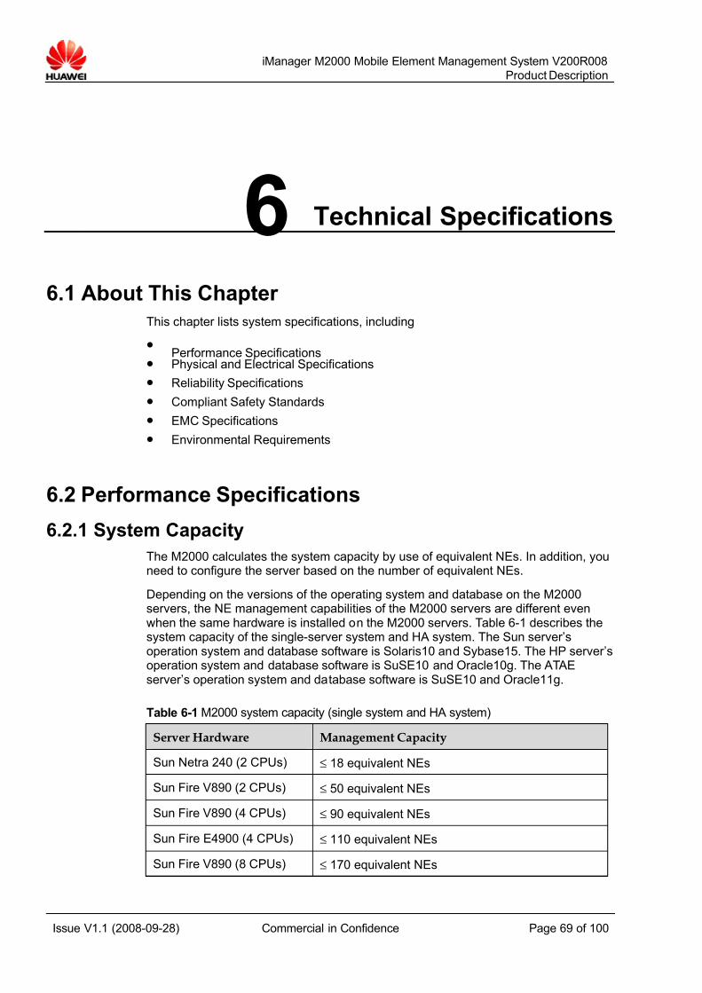
7/14/2019 754002000200008 Oc
http://slidepdf.com/reader/full/754002000200008-oc 69/100
iManager M2000 Mobile Element Management System V200R008
Product Description
Issue V1.1 (2008-09-28) Commercial in Confidence Page 69 of 100
6 Technical Specifications
6.1 About This Chapter
This chapter lists system specifications, including
z Performance Specifications
z Physical and Electrical Specifications
z Reliability Specifications
z Compliant Safety Standards
z EMC Specifications
z Environmental Requirements
6.2 Performance Specifications
6.2.1 System Capacity
The M2000 calculates the system capacity by use of equivalent NEs. In addition, youneed to configure the server based on the number of equivalent NEs.
Depending on the versions of the operating system and database on the M2000servers, the NE management capabilities of the M2000 servers are different evenwhen the same hardware is installed on the M2000 servers. Table 6-1 describes thesystem capacity of the single-server system and HA system. The Sun server’soperation system and database software is Solaris10 and Sybase15. The HP server’soperation system and database software is SuSE10 and Oracle10g. The ATAEserver’s operation system and database software is SuSE10 and Oracle11g.
Table 6-1 M2000 system capacity (single system and HA system)
Server Hardware Management Capacity
Sun Netra 240 (2 CPUs) ≤ 18 equivalent NEs
Sun Fire V890 (2 CPUs) ≤ 50 equivalent NEs
Sun Fire V890 (4 CPUs) ≤ 90 equivalent NEs
Sun Fire E4900 (4 CPUs) ≤ 110 equivalent NEs
Sun Fire V890 (8 CPUs) ≤ 170 equivalent NEs

7/14/2019 754002000200008 Oc
http://slidepdf.com/reader/full/754002000200008-oc 70/100
iManager M2000 Mobile Element Management System V200R008
Product Description
Issue V1.1 (2008-09-28) Commercial in Confidence Page 70 of 100
Server Hardware Management Capacity
Sun Fire E4900 (8 CPUs) ≤ 200 equivalent NEs
Sun Fire E4900 (12 CPUs) ≤ 250 equivalent NEs
2 CPU HP rx2660 ≤ 20 equivalent NEs
4 CPU HP rx7640 ≤ 150 equivalent NEs
6 CPU HP rx7640 ≤ 200 equivalent NEs
8 CPU HP rx7640 ≤ 250 equivalent NEs
2CPU ATAE ≤ 18 equivalent NEs
The number of equivalent NEs is associated with the following factors:z NE type
z Performance measurement period
z Performance measurement object
z Performance measurement counter
For NEs of the same type, the number of equivalent NEs varies with differentmeasurement requirements proposed by customers.
Table 6-2 and Table 6-3 lists the number of equivalent NEs for common measurementand maximum measurement when the measurement period is 60 minutes. To get thenumber of equivalent NEs for the measurements unavailable in the list, contactHuawei engineers for analysis and calculation. The number of equivalent NEs for theIP networking devices is 0.
In the Table 6-2 and Table 6-3, the symbol "-" indicates that the measurement requirements for the NE have no impact on the number of equivalent NEs.
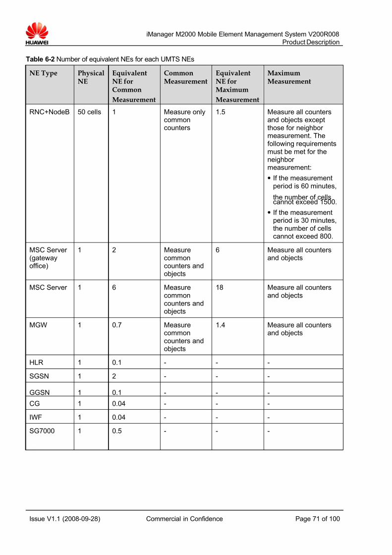
7/14/2019 754002000200008 Oc
http://slidepdf.com/reader/full/754002000200008-oc 71/100
iManager M2000 Mobile Element Management System V200R008
Product Description
Issue V1.1 (2008-09-28) Commercial in Confidence Page 71 of 100
Table 6-2 Number of equivalent NEs for each UMTS NEs
NE Type PhysicalNE
EquivalentNE forCommon
Measurement
CommonMeasurement
EquivalentNE forMaximum
Measurement
MaximumMeasurement
RNC+NodeB 50 cells 1 Measure onlycommoncounters
1.5 Measure all countersand objects exceptthose for neighbor measurement. Thefollowing requirementsmust be met for theneighbor measurement:
z If the measurementperiod is 60 minutes,
the number of cellscannot exceed 1500.
z If the measurementperiod is 30 minutes,the number of cellscannot exceed 800.
MSC Server (gatewayoffice)
1 2 Measurecommoncounters andobjects
6 Measure all countersand objects
MSC Server 1 6 Measurecommoncounters andobjects
18 Measure all countersand objects
MGW 1 0.7 Measurecommoncounters andobjects
1.4 Measure all countersand objects
HLR 1 0.1 - - -
SGSN 1 2 - - -
GGSN 1 0.1 - - -
CG 1 0.04 - - -
IWF 1 0.04 - - -
SG7000 1 0.5 - - -
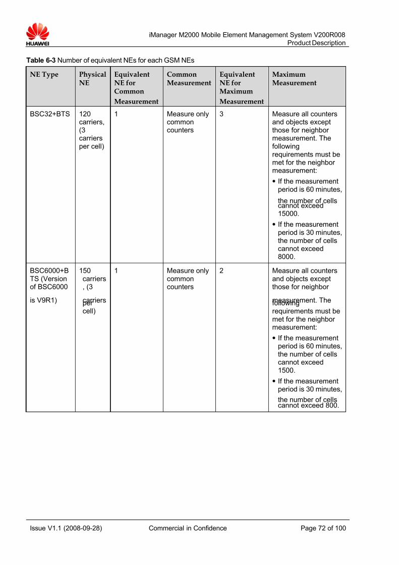
7/14/2019 754002000200008 Oc
http://slidepdf.com/reader/full/754002000200008-oc 72/100
iManager M2000 Mobile Element Management System V200R008
Product Description
Issue V1.1 (2008-09-28) Commercial in Confidence Page 72 of 100
Table 6-3 Number of equivalent NEs for each GSM NEs
NE Type PhysicalNE
EquivalentNE forCommon
Measurement
CommonMeasurement
EquivalentNE forMaximum
Measurement
MaximumMeasurement
BSC32+BTS 120carriers,(3carriersper cell)
1 Measure onlycommoncounters
3 Measure all countersand objects exceptthose for neighbor measurement. Thefollowingrequirements must bemet for the neighbor measurement:
z If the measurementperiod is 60 minutes,
the number of cellscannot exceed15000.
z If the measurementperiod is 30 minutes,the number of cellscannot exceed8000.
BSC6000+BTS (Versionof BSC6000
is V9R1)
150carriers, (3
carriersper cell)
1 Measure onlycommoncounters
2 Measure all countersand objects exceptthose for neighbor
measurement. Thefollowingrequirements must bemet for the neighbor measurement:
z If the measurementperiod is 60 minutes,the number of cellscannot exceed1500.
z If the measurementperiod is 30 minutes,
the number of cellscannot exceed 800.

7/14/2019 754002000200008 Oc
http://slidepdf.com/reader/full/754002000200008-oc 73/100
iManager M2000 Mobile Element Management System V200R008
Product Description
Issue V1.1 (2008-09-28) Commercial in Confidence Page 73 of 100
NE Type PhysicalNE
EquivalentNE forCommonMeasurement
CommonMeasurement
EquivalentNE forMaximumMeasurement
MaximumMeasurement
BSC6000+BTS (Versionof BSC6000is V9R3)
150carriers,(3carriersper cell)
1 Measure onlycommoncounters
2.5 Measure all countersand objects exceptthose for neighbor measurement. Thefollowingrequirements must bemet for the neighbor measurement:
z If the measurementperiod is 60 minutes,the number of cells
cannot exceed1500.
z If the measurementperiod is 30 minutes,the number of cellscannot exceed 800.
BSC6000+BTS
(Version of BSC6000 isV9R8. The
PCU isinternallyinstalled.Number of equivalentNEs is notindividuallycalculated for the PCU.)
150carriers,(3carriersper cell)
1.5 Measure onlycommoncounters,including PSservice
4 Measure all countersand objects exceptthose for the carrier slot and neighbor measurement. Thefollowingrequirements must bemet for the neighbor measurement:
z If the measurementperiod is 60 minutes,the number of cellscannot exceed1500.
z If the measurementperiod is 30 minutes,the number of cells
cannot exceed 800.

7/14/2019 754002000200008 Oc
http://slidepdf.com/reader/full/754002000200008-oc 74/100
iManager M2000 Mobile Element Management System V200R008
Product Description
Issue V1.1 (2008-09-28) Commercial in Confidence Page 74 of 100
NE Type PhysicalNE
EquivalentNE forCommonMeasurement
CommonMeasurement
EquivalentNE forMaximumMeasurement
MaximumMeasurement
GT800BSC+BTS
120carriers,(3carriersper cell)
1 Measure onlycommoncounters
3 Measure all countersand objects exceptthose for neighbor measurement. Thefollowingrequirements must bemet for the neighbor measurement:
z If the measurementperiod is 60 minutes,the number of cells
cannot exceed15000.
z If the measurementperiod is 30 minutes,the number of cellscannot exceed8000.
PCU/PCU6000
180carriers,(3carriersper cell)
1 Measure onlycommoncounters
1.8 Measure all counters
MSC 1 1 - - -
MSC Server (gatewayoffice)
1 2 Measurecommoncounters andobjects
6 Measure all countersand objects
MSC Server 1 6 Measure
commoncounters andobjects
18 Measure all counters
and objects
MGW 1 0.7 Measurecommoncounters andobjects
1.4 Measure all countersand objects
HLR 1 0.1 - - -
SGSN 1 2 - - -
GGSN 1 0.1 - - -
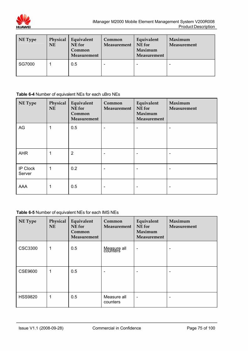
7/14/2019 754002000200008 Oc
http://slidepdf.com/reader/full/754002000200008-oc 75/100
iManager M2000 Mobile Element Management System V200R008
Product Description
Issue V1.1 (2008-09-28) Commercial in Confidence Page 75 of 100
NE Type PhysicalNE
EquivalentNE forCommonMeasurement
CommonMeasurement
EquivalentNE forMaximumMeasurement
MaximumMeasurement
SG7000 1 0.5 - - -
Table 6-4 Number of equivalent NEs for each uBro NEs
NE Type PhysicalNE
EquivalentNE forCommonMeasurement
CommonMeasurement
EquivalentNE forMaximumMeasurement
MaximumMeasurement
AG 1 0.5 - - -
AHR 1 2 - - -
IP ClockServer
1 0.2 - - -
AAA 1 0.5 - - -
Table 6-5 Number of equivalent NEs for each IMS NEs
NE Type PhysicalNE
EquivalentNE forCommonMeasurement
CommonMeasurement
EquivalentNE forMaximumMeasurement
MaximumMeasurement
CSC3300 1 0.5 Measure allcounters
- -
CSE9600 1 0.5 - - -
HSS9820 1 0.5 Measure allcounters
- -

7/14/2019 754002000200008 Oc
http://slidepdf.com/reader/full/754002000200008-oc 76/100
iManager M2000 Mobile Element Management System V200R008
Product Description
Issue V1.1 (2008-09-28) Commercial in Confidence Page 76 of 100
NE Type PhysicalNE
EquivalentNE forCommonMeasurement
CommonMeasurement
EquivalentNE forMaximumMeasurement
MaximumMeasurement
MediaX3600 1 0.5 - - -
ETAS9960 1 0.5 - - -
MRC6600 1 0.5 - - -
MRP6600 1 0.5 - - -
RM9000 1 0.5 Measure allcounters
- -
ATS9900 1 0.5 - - -
iCG9815 1 0.5 Measure allcounters
- -
SE2300 1 0.5 Measure allcounters
- -
6.2.2 Bandwidth
The bandwidth required between the M2000 client and the M2000 server is 512 kbit/s.The bandwidth required between the NMS and the M2000 server is 256 kbit/s.
The bandwidth between the M2000 and the managed NEs varies according to the NEtype, the bandwidth required between the IP devices and the M2000 server is 16kbit/s. The requirement for bandwidth of the NEs in the UTRAN and GBSS variesaccording to the number of managed NodeBs or BTSs.
z
If NodeBs are directly connected to the M2000, the required bandwidth betweeneach NodeB and the M2000 is 64 kbit/s.
z The bandwidth between the M2000 and IMS NEs are provided by the IMSnetwork.
z If the Citrix networking solution is used, the required bandwidth between eachoperation terminal and the Citrix server is 64 kbit/s.
Table 6-6 lists the bandwidth requirements for managing UTRAN NEs.
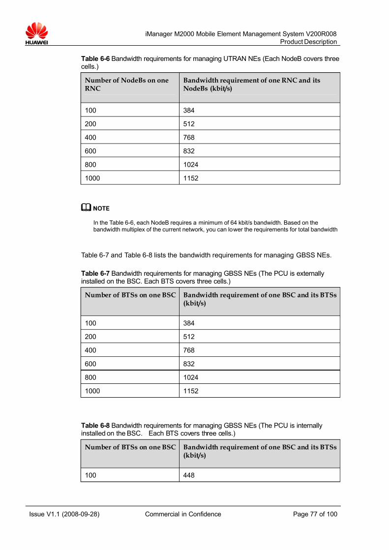
7/14/2019 754002000200008 Oc
http://slidepdf.com/reader/full/754002000200008-oc 77/100
iManager M2000 Mobile Element Management System V200R008
Product Description
Issue V1.1 (2008-09-28) Commercial in Confidence Page 77 of 100
Table 6-6 Bandwidth requirements for managing UTRAN NEs (Each NodeB covers threecells.)
Number of NodeBs on oneRNC
Bandwidth requirement of one RNC and itsNodeBs (kbit/s)
100 384
200 512
400 768
600 832
800 1024
1000 1152
In the Table 6-6, each NodeB requires a minimum of 64 kbit/s bandwidth. Based on thebandwidth multiplex of the current network, you can lower the requirements for total bandwidth
Table 6-7 and Table 6-8 lists the bandwidth requirements for managing GBSS NEs.
Table 6-7 Bandwidth requirements for managing GBSS NEs (The PCU is externallyinstalled on the BSC. Each BTS covers three cells.)
Number of BTSs on one BSC Bandwidth requirement of one BSC and its BTSs(kbit/s)
100 384
200 512
400 768
600 832
800 1024
1000 1152
Table 6-8 Bandwidth requirements for managing GBSS NEs (The PCU is internallyinstalled on the BSC. Each BTS covers three cells.)
Number of BTSs on one BSC Bandwidth requirement of one BSC and its BTSs(kbit/s)
100 448
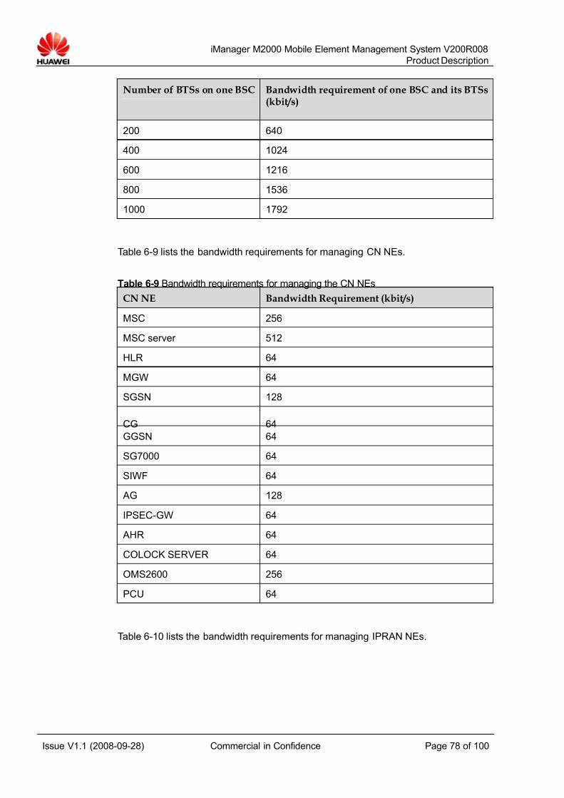
7/14/2019 754002000200008 Oc
http://slidepdf.com/reader/full/754002000200008-oc 78/100
iManager M2000 Mobile Element Management System V200R008
Product Description
Issue V1.1 (2008-09-28) Commercial in Confidence Page 78 of 100
Number of BTSs on one BSC Bandwidth requirement of one BSC and its BTSs(kbit/s)
200 640
400 1024
600 1216
800 1536
1000 1792
Table 6-9 lists the bandwidth requirements for managing CN NEs.
Table 6-9 Bandwidth requirements for managing the CN NEs
CN NE Bandwidth Requirement (kbit/s)
MSC 256
MSC server 512
HLR 64
MGW 64
SGSN 128
CG 64
GGSN 64
SG7000 64
SIWF 64
AG 128
IPSEC-GW 64
AHR 64
COLOCK SERVER 64
OMS2600 256
PCU 64
Table 6-10 lists the bandwidth requirements for managing IPRAN NEs.
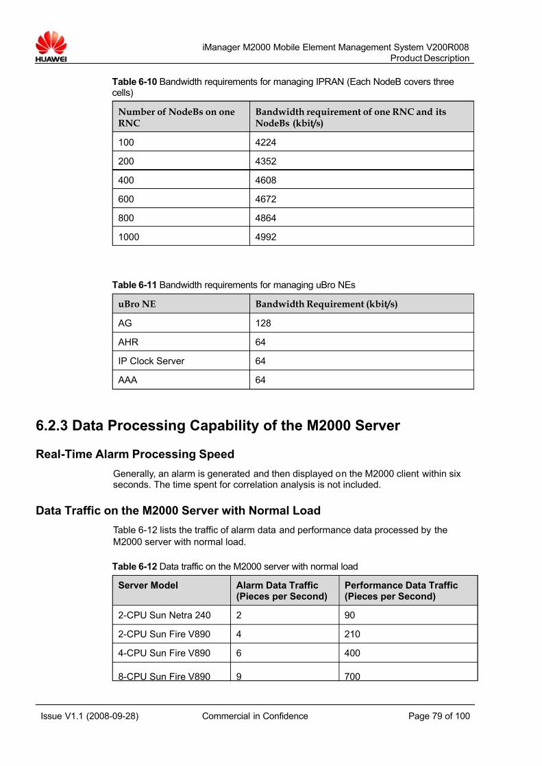
7/14/2019 754002000200008 Oc
http://slidepdf.com/reader/full/754002000200008-oc 79/100
iManager M2000 Mobile Element Management System V200R008
Product Description
Issue V1.1 (2008-09-28) Commercial in Confidence Page 79 of 100
Table 6-10 Bandwidth requirements for managing IPRAN (Each NodeB covers threecells)
Number of NodeBs on oneRNC
Bandwidth requirement of one RNC and itsNodeBs (kbit/s)
100 4224
200 4352
400 4608
600 4672
800 4864
1000 4992
Table 6-11 Bandwidth requirements for managing uBro NEs
uBro NE Bandwidth Requirement (kbit/s)
AG 128
AHR 64
IP Clock Server 64
AAA 64
6.2.3 Data Processing Capability of the M2000 Server
Real-Time Alarm Processing Speed
Generally, an alarm is generated and then displayed on the M2000 client within sixseconds. The time spent for correlation analysis is not included.
Data Traffic on the M2000 Server with Normal Load
Table 6-12 lists the traffic of alarm data and performance data processed by the
M2000 server with normal load.
Table 6-12 Data traffic on the M2000 server with normal load
Server Model Alarm Data Traffic(Pieces per Second)
Performance Data Traffic(Pieces per Second)
2-CPU Sun Netra 240 2 90
2-CPU Sun Fire V890 4 210
4-CPU Sun Fire V890 6 400
8-CPU Sun Fire V890 9 700
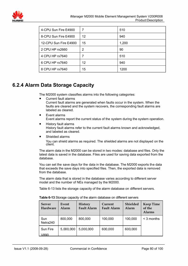
7/14/2019 754002000200008 Oc
http://slidepdf.com/reader/full/754002000200008-oc 80/100
iManager M2000 Mobile Element Management System V200R008
Product Description
Issue V1.1 (2008-09-28) Commercial in Confidence Page 80 of 100
4-CPU Sun Fire E4900 7 510
8-CPU Sun Fire E4900 12 940
12-CPU Sun Fire E4900 15 1,200
2 CPU HP rx2660 2 90
4 CPU HP rx7640 7 510
6 CPU HP rx7640 12 940
8 CPU HP rx7640 15 1200
6.2.4 Alarm Data Storage Capacity
The M2000 system classifies alarms into the following categories:z Current fault alarms
Current fault alarms are generated when faults occur in the system. When thefaults are cleared and the system recovers, the corresponding fault alarms arelabeled as cleared.
z Event alarmsEvent alarms report the current status of the system during the system operation.
z History fault alarmsHistory fault alarms refer to the current fault alarms known and acknowledged,and labeled as cleared.
z Shielded alarms
You can shield alarms as required. The shielded alarms are not displayed on theclient.
The alarm data in the M2000 can be stored in two modes: database and files. Only thelatest data is saved in the database. Files are used for saving data exported from thedatabase.
You can set the save days for the data in the database. The M2000 exports the datathat exceeds the save days into specified files. Then, the exported data is removedfrom the database.
The alarm data that is stored in the database varies according to different server model and the number of NEs managed by the M2000.
Table 6-13 lists the storage capacity of the alarm database on different servers.
Table 6-13 Storage capacity of the alarm database on different servers
ServerHardware
EventAlarm
HistoryFault Alarm
CurrentFault Alarm
ShieldedAlarm
Keep Timeof theAlarms
SunNetra240
800,000 800,000 100,000 100,000
Sun Fire
V890
5,000,000 5,000,000 600,000 600,000
< 3 months

7/14/2019 754002000200008 Oc
http://slidepdf.com/reader/full/754002000200008-oc 81/100
iManager M2000 Mobile Element Management System V200R008
Product Description
Issue V1.1 (2008-09-28) Commercial in Confidence Page 81 of 100
Sun FireE4900
7,000,000 7,000,000 800,000 800,000
HP rx2660 800 000 800 000 100 000 100 000
HP rx7640 7 000 000 7 000 000 800 000 800 000
The number of files containing exported data depends on the remaining disk space of the server.
6.2.5 Alarm Processing Capacity
Table 6-14 lists the peak alarm data processing capabilities of the M2000 configuredwith different server models when alarms are reported continuously for five minutes.
Table 6-14 M2000 alarm processing capability of various servers
Server Peak Alarm Processing Capacity (Record/Second)
Sun Netra 240 (2 CPUs) 20
Sun Fire V890 (2 CPUs) 30
Sun Fire V890 (4 CPUs) 50
Sun Fire E4900 (4 CPUs) 55
Sun Fire V890 (8 CPUs) 90
Sun Fire E4900 (8 CPUs) 100
Sun Fire E4900 (12 CPUs) 125
2 CPU HP rx2660 20
4 CPU HP rx7640 55
6 CPU HP rx7640 100
8 CPU HP rx7640 125
6.2.6 Number of Clients Simultaneously Started on the Server The number of clients that can be started simultaneously on the server varies basedon the server model.
Table 6-15 lists the maximum number of M2000 clients simultaneously started on theserver.

7/14/2019 754002000200008 Oc
http://slidepdf.com/reader/full/754002000200008-oc 82/100
iManager M2000 Mobile Element Management System V200R008
Product Description
Issue V1.1 (2008-09-28) Commercial in Confidence Page 82 of 100
Table 6-15 Maximum number of M2000 clients simultaneously started on the server
Server Model Maximum Number of Clients ConnectedSimultaneously (Controlled by the M2000License)
Sun Netra 240 (2 CPUs) 25
Sun Fire V890 (2 CPUs) 30
Sun Fire V890 (4 CPUs) 40
Sun Fire E4900 (4 CPUs) 50
Sun Fire V890 (8 CPUs) 60
Sun Fire E4900 (8 CPUs) 80
Sun Fire E4900 (12 CPUs) 80
2 CPU HP rx2660 25
4 CPU HP rx7640 50
6 CPU HP rx7640 80
8 CPU HP rx7640 80
6.3 Physical and Electrical Specifications
Table 6-16 lists specifications of different models of M2000 servers.
Table 6-16 Specifications of different models of M2000 server and cabinet (Sun)
Item Specifications
Server model Sun Netra 240 Sun Fire V890 Sun Fire E4900
Server dimensions (W xD x H)
442 mm x 483mm x 87.4 mm
480 mm x 836mm x 714 mm
446 mm x 724 mmx 762 mm
Server weight (kg) 16.3 130.9 131.1
Cabinet N68E-22 N610-22 N610-22 and SunFire Cabinet
Cabinet dimensions (W xD x H)
600 mm x 800mm x 2,200mm
600 mm x 1,000mm x 2,200 mm
N610-22:
600 mm x 1,000mm x 2,200 mm
Sun Fire Cabinet:
609.6 mm x 942.3mm x 1,905 mm
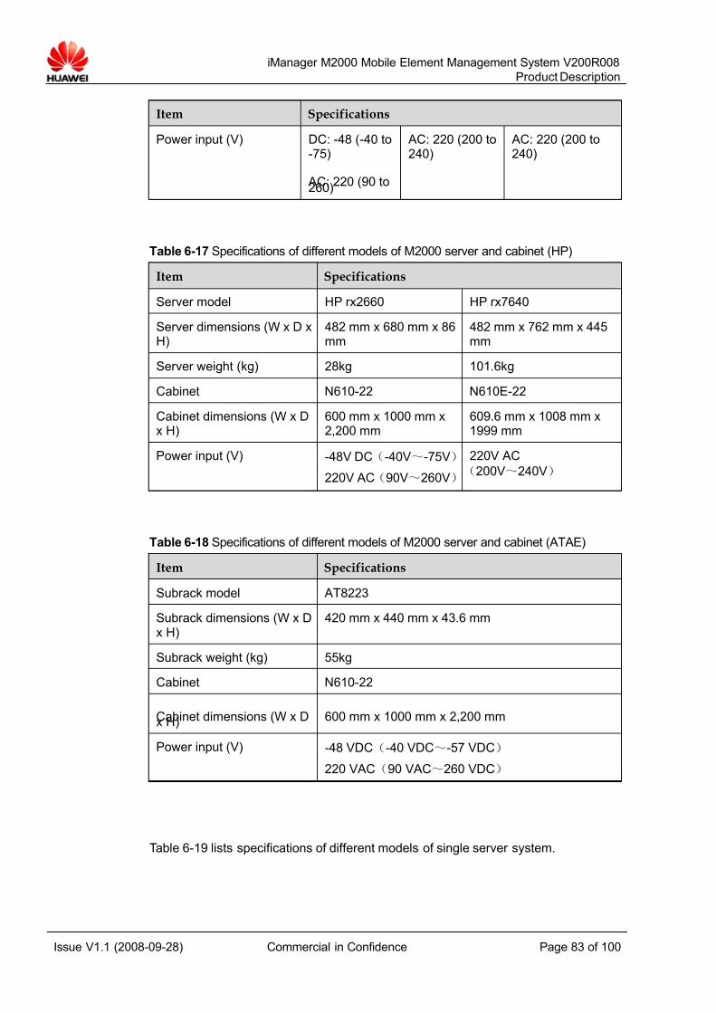
7/14/2019 754002000200008 Oc
http://slidepdf.com/reader/full/754002000200008-oc 83/100
iManager M2000 Mobile Element Management System V200R008
Product Description
Issue V1.1 (2008-09-28) Commercial in Confidence Page 83 of 100
Item Specifications
Power input (V) DC: -48 (-40 to-75)
AC: 220 (90 to260)
AC: 220 (200 to240)
AC: 220 (200 to240)
Table 6-17 Specifications of different models of M2000 server and cabinet (HP)
Item Specifications
Server model HP rx2660 HP rx7640
Server dimensions (W x D xH)
482 mm x 680 mm x 86mm
482 mm x 762 mm x 445mm
Server weight (kg) 28kg 101.6kg
Cabinet N610-22 N610E-22
Cabinet dimensions (W x Dx H)
600 mm x 1000 mm x2,200 mm
609.6 mm x 1008 mm x1999 mm
Power input (V) -48V DC(-40V~-75V)
220V AC(90V~260V)
220V AC
(200V~240V)
Table 6-18 Specifications of different models of M2000 server and cabinet (ATAE)
Item Specifications
Subrack model AT8223
Subrack dimensions (W x Dx H)
420 mm x 440 mm x 43.6 mm
Subrack weight (kg) 55kg
Cabinet N610-22
Cabinet dimensions (W x Dx H) 600 mm x 1000 mm x 2,200 mm
Power input (V) -48 VDC(-40 VDC~-57 VDC)
220 VAC(90 VAC~260 VDC)
Table 6-19 lists specifications of different models of single server system.

7/14/2019 754002000200008 Oc
http://slidepdf.com/reader/full/754002000200008-oc 84/100
iManager M2000 Mobile Element Management System V200R008
Product Description
Issue V1.1 (2008-09-28) Commercial in Confidence Page 84 of 100
Table 6-19 Specifications of different models of single server system
Server Model CabinetType
NumberofCabinets
Quality infullconfiguration
(kg)
Powerconsumption infull configuration
(W)
Sun Netra 240 N68E-22 1 180 1,100
Sun Fire V890 N610-22 1 440 4,150
N610-22 1 300 1,250Sun Fire E4900
Sun Fire 1 350 5,000
HP rx2660 N610-22 1 198.5 1755
HP rx7640 N610E-22 1 271.6 2598
ATAE N610-22 1 160 4800
Table 6-20 lists specifications of different models of HA system.
Table 6-20 Specifications of different models of HA system
Server Model CabinetType
NumberofCabinets
Quality infullconfiguration
(kg)
Powerconsumption infull configuration
(W)
Sun Netra 240 N68E-22 1 270 3,000
Sun Fire V890 N610-22 2 2 x 440 2 x 4,150
N610-22 1 350 1,500Sun FireE4900
Sun Fire 2 350 + 310 5,000 + 4,500
Table 6-21 lists the power consumption of all the equipment in the M2000 system.
Table 6-21 Power consumption of all the equipment in the M2000 system
Equipment Power Consumption (W)
Client 300
Sun Netra 240 DC: 570
AC: 550
Sun Fire V890 3,200
Sun Fire E4900 4,180
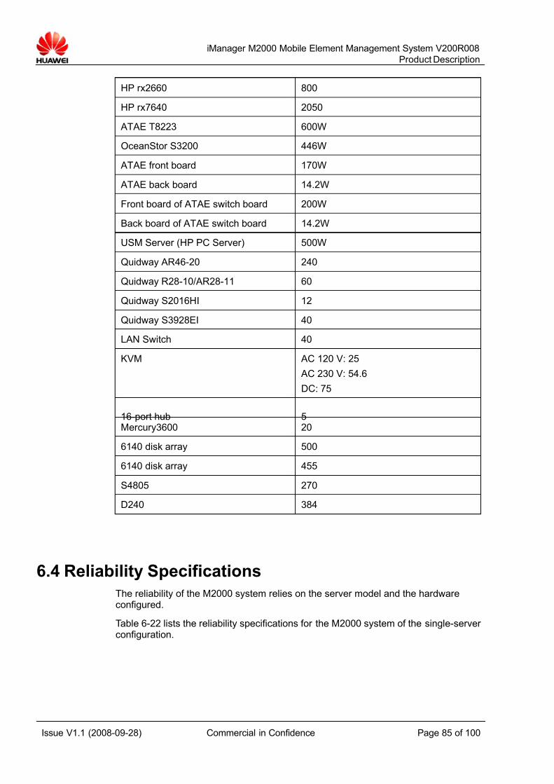
7/14/2019 754002000200008 Oc
http://slidepdf.com/reader/full/754002000200008-oc 85/100
iManager M2000 Mobile Element Management System V200R008
Product Description
Issue V1.1 (2008-09-28) Commercial in Confidence Page 85 of 100
HP rx2660 800
HP rx7640 2050
ATAE T8223 600W
OceanStor S3200 446W
ATAE front board 170W
ATAE back board 14.2W
Front board of ATAE switch board 200W
Back board of ATAE switch board 14.2W
USM Server (HP PC Server) 500W
Quidway AR46-20 240
Quidway R28-10/AR28-11 60
Quidway S2016HI 12
Quidway S3928EI 40
LAN Switch 40
KVM AC 120 V: 25
AC 230 V: 54.6
DC: 75
16-port hub 5Mercury3600 20
6140 disk array 500
6140 disk array 455
S4805 270
D240 384
6.4 Reliability Specifications
The reliability of the M2000 system relies on the server model and the hardwareconfigured.
Table 6-22 lists the reliability specifications for the M2000 system of the single-server configuration.

7/14/2019 754002000200008 Oc
http://slidepdf.com/reader/full/754002000200008-oc 86/100
iManager M2000 Mobile Element Management System V200R008
Product Description
Issue V1.1 (2008-09-28) Commercial in Confidence Page 86 of 100
Table 6-22 Reliability specifications for the M2000 system of the single-server configuration
Server Model MTBF(Hour)
MTTR(Hour)
Annual MeanFailure Time
(Hour)
Availability (%)
Sun Netra 240(2 CPUs)
42 566 1.3095 AC:0.600001
DC:0.644027
AC:99.993151%
DC:99.992648%
Sun Fire V890(2 CPUs)
17 732 0.6557 0.827863 99.990550%
Sun Fire V890(4 CPUs)
16 138 0.5541 1.004873 99.988529%
Sun Fire E4900(4 CPUs)
47 313 0.4483 1.292172 99.985249%
Sun Fire V890(8 CPUs)
15 889 0.4664 0.326885 99.996268%
Sun Fire E4900(8 CPUs)
47 313 0.4483 0.298556 99.996592%
HP rx2660 42566 1.3095 0.522211 99.994039%
4 CPU rx7640 86259 0.6218 0.113924 99.998699%
6 CPU rx7640 83921 0.6218 0.117098 99.998663%
8 CPU rx7640 82198 0.6218 0.119552 99.998635%
ATAE 244 140 0.178679623
0.0064 99.99992681%
Table 6-23 lists the reliability specifications for the M2000 system of the HAconfiguration.
Table 6-23 Reliability specifications for the M2000 system of the HA configuration
Server Model MTBF(Hour)
MTTR(Hour)
Annual MeanFailure Time(Hour)
Availability (%)
Sun Netra 240(2 CPUs)
5 858.0 0.5212 AC: 0.219465
DC: 0.219827
AC: 99.997495%
DC: 99.997491%
Sun Fire V890(2 CPUs)
16 477 1.439 0.213017 99.997568%
Sun Fire V890(4 CPUs)
14 656.0 1.3268 0.208710 99.997617%
Sun Fire E4900(4 CPUs)
23 476.0 0.4419 0.204449 99.997701%
7/14/2019 754002000200008 Oc
http://slidepdf.com/reader/full/754002000200008-oc 87/100
iManager M2000 Mobile Element Management System V200R008
Product Description
Issue V1.1 (2008-09-28) Commercial in Confidence Page 87 of 100
Sun Fire V890(8 CPUs)
9 817.0 1.0873 0.189961 99.997831%
Sun Fire E4900(8 CPUs)
23 476.0 0.4419 0.185203 99.997886%
6.5 Compliant Safety Standards
The M2000 complies with the following safety standards:
z IEC 60950-1
z IEC/EN41003
z EN 60950-1
z UL 60950-1
z CSA C22.2 No 60950-1
z AS/NZS 60950-1
z BS EN 60950-1
z IS 13252
z GB4943
6.6 EMC Specifications
The M2000 complies with the following Electromagnetic Compatibility (EMC)
standards:
z CISPR22 Class A
z EN55022 Class A
z EN50024
z ETSI EN 300 386 Serial Class A
z ETSI EN 301 489 Class A
z ICES 003 Class A
z AS/NZS CISPR22 Class A
z GB9254 Class A
z VCCI Class A
z CNS 13438 Class A
6.7 Environmental Requirements
Environmental requirements include the requirements for the storage, transportation,and operation of the equipment.
The environmental requirements comply with the following two standards:
z ETS 300019 "Equipment Engineering (EE); Environmental conditions andenvironmental tests for telecom equipment"
7/14/2019 754002000200008 Oc
http://slidepdf.com/reader/full/754002000200008-oc 88/100
iManager M2000 Mobile Element Management System V200R008
Product Description
Issue V1.1 (2008-09-28) Commercial in Confidence Page 88 of 100
z IEC 60721 "Classification of environmental conditions"
7/14/2019 754002000200008 Oc
http://slidepdf.com/reader/full/754002000200008-oc 89/100
iManager M2000 Mobile Element Management System V200R008
Product Description
Issue V1.1 (2008-09-28) Commercial in Confidence Page 89 of 100
6.7.1 Storage Environment
This section describes the climatic, waterproof, biological, air purity, and mechanicalstress requirements for equipment storage.
Climatic Requirements
Table 6-24 lists the climatic requirements for equipment storage.
Table 6-24 Climatic requirements for the equipment storage
Item Range
Altitude ≤ 5,000 m
Air pressure 70 kPa to 106 kPa
Temperature 0°C to +40°C
Temperature changerate
≤ 1oC/min
Relative humidity 10% to 100%
Solar radiation ≤ 1,120 W/s²
Heat radiation ≤ 600 W/s²
Wind speed ≤ 30 m/s
Waterproof Requirements
The equipment must be stored in a room where:
z No water accumulates on the ground or falls on the package.
z The equipment is kept away from water sources such as a hydrant andair-conditioner.
If the equipment is placed outdoors, ensure that:
z The package is intact.
z Waterproof measures are applied to prevent water penetration.
z No water accumulates on the ground or flows into the package.
z The package is not exposed directly to sunlight.
Biological Requirements
Ensure that the place for equipment storage is free of:
z Fungus or mildew
z Rodents, such as rats

7/14/2019 754002000200008 Oc
http://slidepdf.com/reader/full/754002000200008-oc 90/100
iManager M2000 Mobile Element Management System V200R008
Product Description
Issue V1.1 (2008-09-28) Commercial in Confidence Page 90 of 100
Air Purity Requirements
The air must be free of explosive, conductive, magnetic conductive or corrosive dust.
The density of physically active materials must comply with the requirements listed in
Table 6-25.
Table 6-25 Storage requirements for physically active materials
Physically Active Material Unit Density
Suspended dust mg/m³ ≤ 5.00
Falling dust mg/m²·h ≤ 20.0
Sand mg/m³ ≤ 300
Note:
Suspended dust: Diameter ≤ 75 μmFalling dust: 75 μm ≤ Diameter ≤ 150 μm
Sand: 150 μm ≤ Diameter ≤ 1 000 μm
The density of chemically active materials must comply with the requirements listed inTable 6-26.
Table 6-26 Storage requirements for chemically active materials
Chemically Active Material Unit Density
SO2 mg/m³ ≤ 0.30
H2S mg/m³ ≤ 0.10
NO2 mg/m³ ≤ 0.50
NH3 mg/m³ ≤ 1.00
Cl2 mg/m³ ≤ 0.10
HCl mg/m³ ≤ 0.10
HF mg/m³ ≤ 0.01
O3 mg/m³ ≤ 0.05
7/14/2019 754002000200008 Oc
http://slidepdf.com/reader/full/754002000200008-oc 91/100
iManager M2000 Mobile Element Management System V200R008
Product Description
Issue V1.1 (2008-09-28) Commercial in Confidence Page 91 of 100
Mechanical Stress Requirements
Table 6-27 lists the mechanical stress that the equipment can endure during storage.
Table 6-27 Storage requirements regarding mechanical stress
Item Sub-Item Range
Offset ≤ 7.0 mm None
Accelerated speed None ≤ 20.0 m/s²
Sinusoidalvibration
Frequency range 2 Hz to 9 Hz 9 Hz to 200 Hz
Impact responsespectrum II
≤ 250 m/s²Unsteady impact
Static payload ≤ 5 kPa
Note:
Impact response spectrum: refers to the maximum acceleration response curve generated bythe equipment under specified impact excitation. Impact response spectrum II means that theduration of semi-sine impact response spectrum is 6 ms.
Static payload: refers to the capability of the equipment to bear the pressure from the top when itis packed in the normal pile-up method.
6.7.2 Transportation Environment
This section describes the climatic, waterproof, biological, air purity, and mechanical
stress requirements for equipment transportation.
Climatic Requirements
Table 6-28 lists the climatic requirements for the transportation of the equipment.
Table 6-28 Climatic requirements for transporting the equipment
Item Range
Altitude ≤ 5,000 m
Air pressure 70 kPa to 106 kPa
Temperature 0 °C to +40 °C
Temperature change rate ≤ 3°C/min
Humidity 5% to 100%
Solar radiation ≤ 1, 120 W/s²
Heat radiation ≤ 600 W/s²
Wind speed ≤ 30 m/s
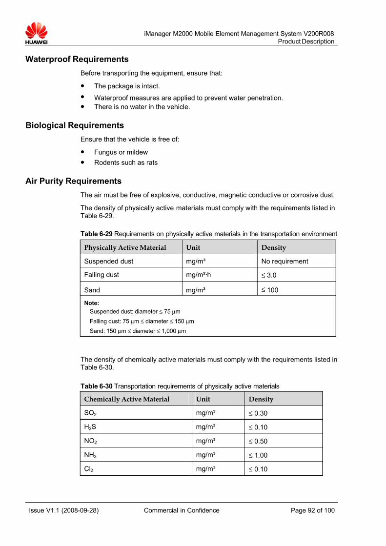
7/14/2019 754002000200008 Oc
http://slidepdf.com/reader/full/754002000200008-oc 92/100
iManager M2000 Mobile Element Management System V200R008
Product Description
Issue V1.1 (2008-09-28) Commercial in Confidence Page 92 of 100
Waterproof Requirements
Before transporting the equipment, ensure that:
z The package is intact.
z Waterproof measures are applied to prevent water penetration.
z There is no water in the vehicle.
Biological Requirements
Ensure that the vehicle is free of:
z Fungus or mildew
z Rodents such as rats
Air Purity Requirements
The air must be free of explosive, conductive, magnetic conductive or corrosive dust.
The density of physically active materials must comply with the requirements listed inTable 6-29.
Table 6-29 Requirements on physically active materials in the transportation environment
Physically Active Material Unit Density
Suspended dust mg/m³ No requirement
Falling dust mg/m²·h ≤ 3.0
Sand mg/m³ ≤ 100
Note:
Suspended dust: diameter ≤ 75 μm
Falling dust: 75 μm ≤ diameter ≤ 150 μm
Sand: 150 μm ≤ diameter ≤ 1,000 μm
The density of chemically active materials must comply with the requirements listed inTable 6-30.
Table 6-30 Transportation requirements of physically active materials
Chemically Active Material Unit Density
SO2 mg/m³ ≤ 0.30
H2S mg/m³ ≤ 0.10
NO2 mg/m³ ≤ 0.50
NH3 mg/m³ ≤ 1.00
Cl2 mg/m³ ≤ 0.10
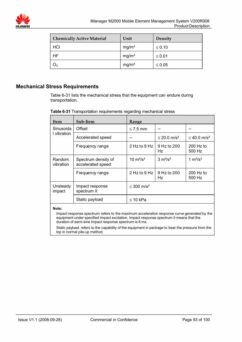
7/14/2019 754002000200008 Oc
http://slidepdf.com/reader/full/754002000200008-oc 93/100
iManager M2000 Mobile Element Management System V200R008
Product Description
Issue V1.1 (2008-09-28) Commercial in Confidence Page 93 of 100
Chemically Active Material Unit Density
HCl mg/m³ ≤ 0.10
HF mg/m³ ≤ 0.01
O3 mg/m³ ≤ 0.05
Mechanical Stress Requirements
Table 6-31 lists the mechanical stress that the equipment can endure duringtransportation.
Table 6-31 Transportation requirements regarding mechanical stress
Item Sub-Item Range
Offset ≤ 7.5 mm -- --
Accelerated speed -- ≤ 20.0 m/s² ≤ 40.0 m/s²
Sinusoidal vibration
Frequency range 2 Hz to 9 Hz 9 Hz to 200Hz
200 Hz to500 Hz
Spectrum density of accelerated speed
10 m²/s³ 3 m²/s³ 1 m²/s³Randomvibration
Frequency range 2 Hz to 9 Hz 9 Hz to 200Hz
200 Hz to500 Hz
Impact responsespectrum II
≤ 300 m/s²Unsteadyimpact
Static payload ≤ 10 kPa
Note:
Impact response spectrum: refers to the maximum acceleration response curve generated by theequipment under specified impact excitation. Impact response spectrum II means that theduration of semi-sine impact response spectrum is 6 ms.
Static payload: refers to the capability of the equipment in package to bear the pressure from thetop in normal pile-up method.
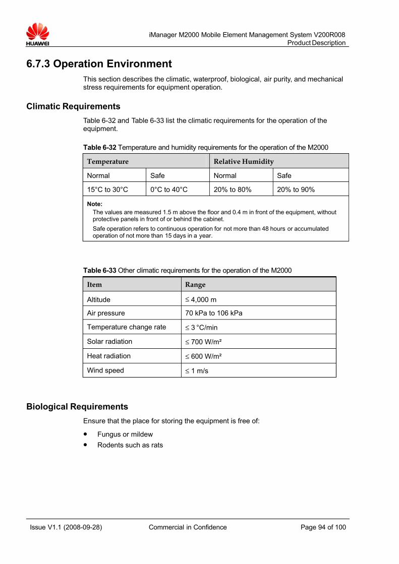
7/14/2019 754002000200008 Oc
http://slidepdf.com/reader/full/754002000200008-oc 94/100
iManager M2000 Mobile Element Management System V200R008
Product Description
Issue V1.1 (2008-09-28) Commercial in Confidence Page 94 of 100
6.7.3 Operation Environment
This section describes the climatic, waterproof, biological, air purity, and mechanicalstress requirements for equipment operation.
Climatic Requirements
Table 6-32 and Table 6-33 list the climatic requirements for the operation of theequipment.
Table 6-32 Temperature and humidity requirements for the operation of the M2000
Temperature Relative Humidity
Normal Safe Normal Safe
15°C to 30°C 0°C to 40°C 20% to 80% 20% to 90%
Note:
The values are measured 1.5 m above the floor and 0.4 m in front of the equipment, withoutprotective panels in front of or behind the cabinet.
Safe operation refers to continuous operation for not more than 48 hours or accumulatedoperation of not more than 15 days in a year.
Table 6-33 Other climatic requirements for the operation of the M2000
Item Range
Altitude ≤ 4,000 m
Air pressure 70 kPa to 106 kPa
Temperature change rate ≤ 3 °C/min
Solar radiation ≤ 700 W/m²
Heat radiation ≤ 600 W/m²
Wind speed ≤ 1 m/s
Biological Requirements
Ensure that the place for storing the equipment is free of:
z Fungus or mildew
z Rodents such as rats
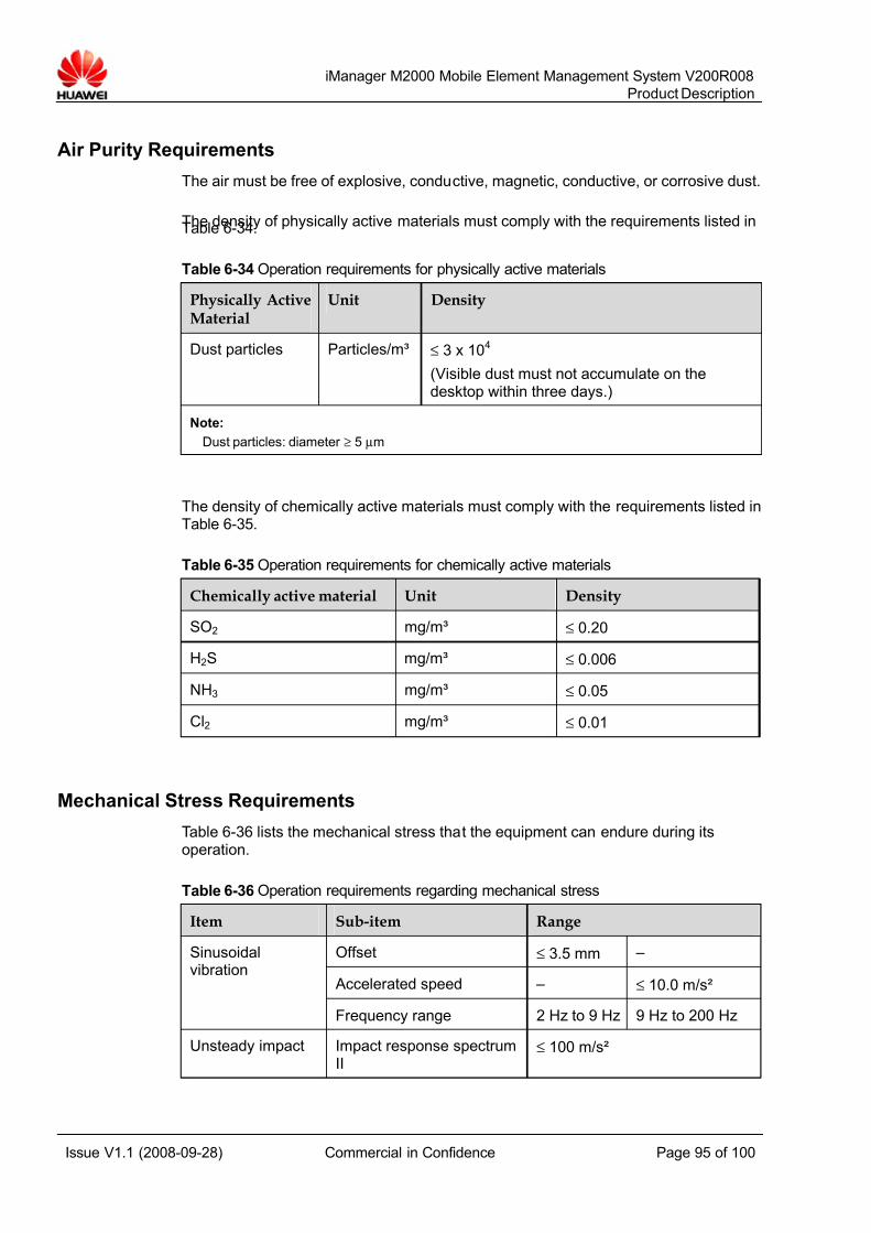
7/14/2019 754002000200008 Oc
http://slidepdf.com/reader/full/754002000200008-oc 95/100
iManager M2000 Mobile Element Management System V200R008
Product Description
Issue V1.1 (2008-09-28) Commercial in Confidence Page 95 of 100
Air Purity Requirements
The air must be free of explosive, conductive, magnetic, conductive, or corrosive dust.
The density of physically active materials must comply with the requirements listed inTable 6-34.
Table 6-34 Operation requirements for physically active materials
Physically ActiveMaterial
Unit Density
Dust particles Particles/m³ ≤ 3 x 10⁴
(Visible dust must not accumulate on thedesktop within three days.)
Note:
Dust particles: diameter ≥ 5 μm
The density of chemically active materials must comply with the requirements listed inTable 6-35.
Table 6-35 Operation requirements for chemically active materials
Chemically active material Unit Density
SO2 mg/m³ ≤ 0.20
H2S mg/m³ ≤ 0.006
NH3 mg/m³ ≤ 0.05
Cl2 mg/m³ ≤ 0.01
Mechanical Stress Requirements
Table 6-36 lists the mechanical stress that the equipment can endure during itsoperation.
Table 6-36 Operation requirements regarding mechanical stress
Item Sub-item Range
Offset ≤ 3.5 mm –
Accelerated speed – ≤ 10.0 m/s²
Sinusoidalvibration
Frequency range 2 Hz to 9 Hz 9 Hz to 200 Hz
Unsteady impact Impact response spectrumII
≤ 100 m/s²
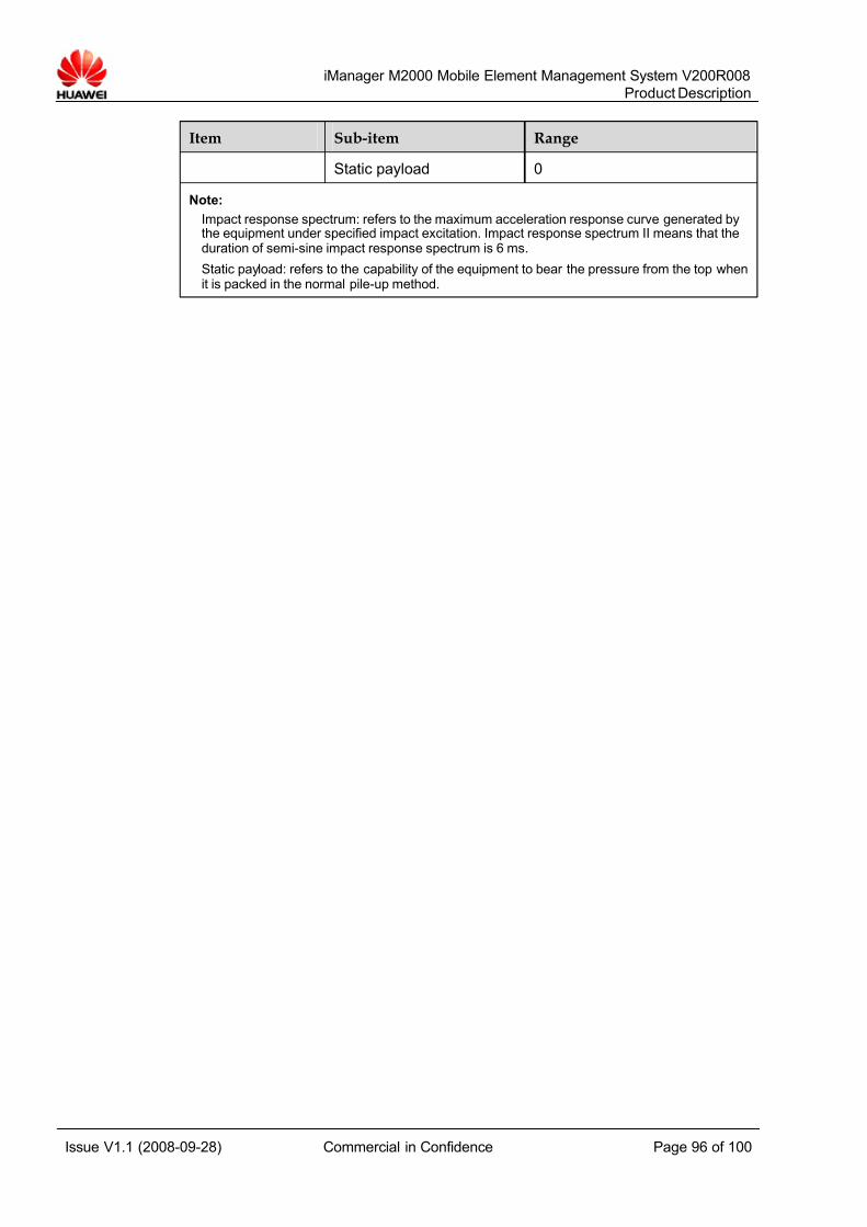
7/14/2019 754002000200008 Oc
http://slidepdf.com/reader/full/754002000200008-oc 96/100
iManager M2000 Mobile Element Management System V200R008
Product Description
Issue V1.1 (2008-09-28) Commercial in Confidence Page 96 of 100
Item Sub-item Range
Static payload 0
Note:
Impact response spectrum: refers to the maximum acceleration response curve generated bythe equipment under specified impact excitation. Impact response spectrum II means that theduration of semi-sine impact response spectrum is 6 ms.
Static payload: refers to the capability of the equipment to bear the pressure from the top whenit is packed in the normal pile-up method.

7/14/2019 754002000200008 Oc
http://slidepdf.com/reader/full/754002000200008-oc 97/100
iManager M2000 Mobile Element Management System V200R008
Product Description
Issue V1.1 (2008-09-28) Commercial in Confidence Page 97 of 100
A Acronyms and Abbreviations
Numeric3GPP 3rd Generation Partnership Project
A
AC Alternating Current
B
BSC Base Station Controller
BTS Base Transceiver Station
C
CG Charging Gateway
CME Configuration Management Express
CN Core Network
CORBA Common Object Request Broker Architecture
CPU Center Processing Unit
CSV Comma Separation Value
D
DC Direct Current
DDN Digital Data Network
DST Daylight Saving Time
7/14/2019 754002000200008 Oc
http://slidepdf.com/reader/full/754002000200008-oc 98/100
iManager M2000 Mobile Element Management System V200R008
Product Description
Issue V1.1 (2008-09-28) Commercial in Confidence Page 98 of 100
E
EM Element Management
EMC Electromagnetic Compatibility
EMS Element Management System
ETS European Telecommunication Standards
ETSI European Telecommunications Standards Institute
F
FTP File Transfer Protocol
G
GByte Gigabyte
GGSN Gateway GPRS Support Node
GHz Gigahertz
GSM Global System for Mobile communications
GUI Graphic User Interface
H
HA High Availability
HFC HSL Foundation Component
HLR Home Location Register
HSL High-level Script Language
HTML Hyper Text Markup Language
I
ID Identity
IEC International Electrotechnical Commission
IRP Integration Reference Point
Itf-N Northbound Interface
K
KPI Key Performance Index
L
7/14/2019 754002000200008 Oc
http://slidepdf.com/reader/full/754002000200008-oc 99/100
iManager M2000 Mobile Element Management System V200R008
Product Description
Issue V1.1 (2008-09-28) Commercial in Confidence Page 99 of 100
LAN Local Area Network
LMT Local Maintenance Terminal
M
MSC Mobile Service Switching Center
MSCServer
Mobile Service Switching Center Server
MTBF Mean Time Between Failures
MTTR Mean Time To Repair
MGW Media Gate-Way
MML Man Machine Language
N
NMS Network Management System
NodeB WCDMA base station
NTP Network Time Protocol
P
PC Personal Computer
PCU Packet Control Unit
PSTN Public Switched Telephone Network
R
RNC Radio Network Controller
RNS Radio Network System
S
SIWF Shared InterWorking Function
SG Singling Gateway
SGSN Serving GPRS Support Node
SNMP Simple Network Management Protocol
SNTP Simple Network Time Protocol
T
7/14/2019 754002000200008 Oc
http://slidepdf.com/reader/full/754002000200008-oc 100/100
iManager M2000 Mobile Element Management System V200R008
Product Description
TCP Transfer Control Protocol
TMN Telecommunication Management Network
U
UMTS Universal Mobile Telecommunications System
UTRAN UMTS Terrestrial radio access network
V
VPN Virtual Private Network
W
WCDMA Wideband Code Division Multiple Access
X
XML Extensible Markup Language