700‘54 Ascend Aeon
128
Version Innovation with Integrity 700‘54 Ascend Aeon 00 User Manual NMR
Transcript of 700‘54 Ascend Aeon

Version
Innovation with Integrity
700‘54 Ascend Aeon
00
User Manual
NMR

Copyright © by Bruker Corporation
All rights reserved. No part of this publication may be reproduced, stored in a retrieval system, or transmitted, in any form, or by any means without the prior consent of the publisher. Product names used are trademarks or registered trademarks of their respective holders.
This manual was written by
Peter van Bommel
© March, 2014: Bruker Corporation
Faellanden, Switzerland
ZTKS0242 / Z31965 / 00
For further technical assistance on the NMR Magnet System, please do not hesitate to contact your nearest BRUKER dealer or contact us directly at:
BRUKER BioSpin AG Industriestrasse 26 CH–8117 Faellanden Switzerland Phone: + 41 44 825 91 11 FAX: + 41 44 825 96 96 E-mail: [email protected] Internet: www.bruker.com

ZTKS0
0 Contact ...........................................................................................................9
1 Introduction..................................................................................................11
2 Safety............................................................................................................15
3 Transportation .............................................................................................31
4 Assembling ..................................................................................................37
5 Operation......................................................................................................39
6 Troubleshooting ..........................................................................................41
7 Maintenance.................................................................................................83
8 Disassembling .............................................................................................87
A Appendix ......................................................................................................89
3 242 / Z31965 / 00

4 ZTKS0242 / Z31965 / 00

ZTKS0
Table of Contents
0 Contact ...........................................................................................................9
1 Introduction..................................................................................................111.1 General Information................................................................................................ 11
1.2 Limitation of Liability ............................................................................................... 11
1.3 Customer Service................................................................................................... 11
1.4 Warranty................................................................................................................. 11
1.5 Copyright ................................................................................................................ 11
1.6 General View.......................................................................................................... 12
2 Safety............................................................................................................152.1 Approved Persons.................................................................................................. 15
2.2 Customer Responsibilities...................................................................................... 16
2.3 Key Words.............................................................................................................. 17
2.4 Residual Risks........................................................................................................ 18
2.4.1 Persons .................................................................................................................. 18
2.4.2 Intended Use .......................................................................................................... 18
2.4.3 Safety Devices ....................................................................................................... 19
2.4.4 Spare Parts ............................................................................................................ 19
2.4.5 Signs and Labels.................................................................................................... 20
2.4.6 Technical Risks ...................................................................................................... 20
2.5 Personal Protective Equipment .............................................................................. 26
2.6 Description of Signs and Labels............................................................................. 27
2.7 Safety Devices ....................................................................................................... 28
2.8 Behavior in Danger and Emergency Situations...................................................... 30
2.9 Fire Department Notification................................................................................... 30
3 Transportation .............................................................................................313.1 Safety ..................................................................................................................... 31
3.2 Packaging............................................................................................................... 31
3.2.1 Disposal.................................................................................................................. 32
3.3 Transport Inspection............................................................................................... 32
3.4 Transportation by Fork Lift / Pallet Jack ................................................................. 33
3.5 Transportation with a Crane ................................................................................... 34
3.6 Storing .................................................................................................................... 35
3.7 Disposal.................................................................................................................. 35
4 Assembling ..................................................................................................374.1 Safety ..................................................................................................................... 37
5 242 / Z31965 / 00
Table of Contents
5 Operation......................................................................................................395.1 Safety ..................................................................................................................... 39
5.2 Set into Operation................................................................................................... 40
6 Troubleshooting ..........................................................................................416.1 Safety ..................................................................................................................... 41
6.2 Problem .................................................................................................................. 42
6.2.1 During Transportation............................................................................................. 42
6.2.2 During Assembling ................................................................................................. 42
6.2.3 During Cool Down .................................................................................................. 44
6.2.4 During Energizing and Shimming ........................................................................... 48
6.2.5 During Operation of the Magnet Stand................................................................... 50
6.2.6 During Standard Operation..................................................................................... 52
6.2.7 During De-energizing and Warming up .................................................................. 72
6.2.8 During Operation of the Cryogenic Refrigerator ..................................................... 73
6.3 Troubleshooting Work ............................................................................................ 78
6.3.1 After a Quench ....................................................................................................... 78
6.3.2 Procedure in case of an alarm signal ..................................................................... 80
6.3.3 Procedure in case of Cryogenic Refrigerator failure............................................... 81
7 Maintenance.................................................................................................837.1 Safety ..................................................................................................................... 83
7.2 Cleaning ................................................................................................................. 84
7.3 Maintenance Timetable .......................................................................................... 84
7.4 Maintenance Work at the Cryogenic Refrigerator .................................................. 86
8 Disassembling .............................................................................................878.1 Safety ..................................................................................................................... 87
A Appendix ......................................................................................................89A.1 Warning Signs ........................................................................................................ 91
A.2 Figures.................................................................................................................... 93
A.3 Tables..................................................................................................................... 95
A.4 Glossary / Abbreviations......................................................................................... 97
A.5 Technical Data MS 700‘54 Ascend Aeon............................................................... 99
A.6 Index..................................................................................................................... 125
6 ZTKS0242 / Z31965 / 00

ZTKS0
7242 / Z31965 / 00
π
8 ZTKS0242 / Z31965 / 00

ZTKS0
0 Contact
Manufacturer
Bruker BioSpin AG
Industriestrasse 26
CH-8117 Faellanden
Switzerland
Phone: + 41 44 825 91 11
Fax: + 41 44 825 96 96
http://www.bruker.com
E-mail: [email protected]
Please refer to the Model No., Serial No. and Internal Order No. in all correspondence regarding the NMR system or components thereof.
9242 / Z31965 / 00

Contact
10 ZTKS0242 / Z31965 / 00

ZTKS0
1 Introduction
1.1 General Information
This manual contains important information about the handling of the supplied magnet system used for NMR spectroscopy and its components. The compliance with all safety and handling instructions, the applicable local accident prevention and general safety regulations are necessary for safe work.
This manual is part of the product. It must be kept nearby the magnet system and free access must be ensured at any time. Read the manual carefully before handling the magnet system or its components.
1.2 Limitation of Liability
The information in this manual will take into account the current state of the technology.
The manufacturer assumes no liability for damages resulting from:
• non-compliance with the instructions and all applicable documentation,
• use for purposes not intended,
• not sufficiently approved persons,
• arbitrary changes or modifications and
• use of not approved spare parts or accessories.
1.3 Customer Service
Technical support is provided by Bruker Service via telephone or e-mail. For contact information see page 9 of this document.
1.4 Warranty
The warranty terms can be found in the sales documents of the magnet system and in the Terms and Conditions of Bruker BioSpin AG.
1.5 Copyright
No part of this publication may be reproduced, stored in a retrieval system, or transmit-ted, in any form or by any means without the prior consent of the publisher. Product names used are trademarks or registered trademarks of their respective holders.
11242 / Z31965 / 00

Introduction
1.6 General View
Figure 1.1: General view a Magnet System with Aeon /RZ Cryostat
1 Cryogenic Refrigerator Compressor
2 Cryogenic Refrigerator Flex Lines
3 Rotary Valve (RV) covered by the Rotary Valve Column (RVC)
4 Connecting Line
5 Helium Flow System
6 Current lead turret
7 Cryogenic Refrigerator Cold Head
8 Helium Fill-in Turret with helium fill-in port
9 RT bore
10 RT vessel
11 Magnet Stand
12 ZTKS0242 / Z31965 / 00

ZTKS0
Introduction
The heart of the NMR magnet system is a superconducting magnet located inside the helium vessel, which is filled with liquid helium. The helium vessel is surrounded by a radiation shield (RS) both cooled by a Cryogenic Refrigerator. The outer casing, the room temperature (RT) vessel (10) contains the helium vessel and the radiation shield. The vacuum inside the RT vessel reduces thermal conduction. The RT bore (9) allows the access to the magnetic center. RT vessel, helium vessel, radiation shield, helium turrets, flow system and the RT bore together build the cryostat of the magnet system.
The cryostat is mounted on a magnet stand (11). The isolators in the magnet stand absorb floor vibrations. Different heights and isolators are available optionally.
The helium turrets (6, 8) connected with the helium flow system (5) are the interface of the helium vessel and the magnet coil. The helium fill-in turret (8) is marked with a yellow label. The current lead turret (6) is the interface for energizing the magnet coil and for diagnostic.
The Cryogenic Refrigerator is a closed loop helium expansion cycle. It consists of a Compressor (1), two Flex Lines (2), a remote Rotary Valve inside the Rotary Valve Column (RVC; 3), a Cold Head (7) and a Connecting Line (4) between Rotary Valve and Cold Head. The Rotary Valve, Flex Lines, Connecting Line and Cold Head are covered with an applicable noise protection cover. For the Compressor a noise protection is available optionally. Depending on the customers site restrictions several options of the Cryogenic Refrigerator are possible. Refer to the order subscription and to the supplied manuals of the supplied equipment.
13 242 / Z31965 / 00

Introduction
14 ZTKS0242 / Z31965 / 00

ZTKS0
2 Safety
The supplied cryostat and further equipment of the magnet system were designed and manufactured according to best available technical knowledge and practice, achieved in over 50 years of experience of Bruker Corporation. International standards for quality and approval recommended for cryostats of superconducting magnets were certified.
Nevertheless non-compliance with the following instructions and safety advice may cause serious hazards and property damage.
2.1 Approved Persons
Bruker BioSpin AG identifies the following qualifications for personnel performing tasks on the magnet system or its components:
Approved Customer Personnel
As a result of professional training by Bruker Service Personnel, experience and knowledge of applicable regulations these persons are qualified to perform the specific tasks on the magnet system and its components assigned to them in this manual. Approved Customer Personnel are qualified to identify possible hazards and risks associated with the tasks assigned to them and to perform all possible steps to eliminate or minimize these risks.
Bruker Service Personnel
These persons are qualified by appropriate qualification and professional training and experience (including all necessary knowledge of applicable regulations and regulatory requirements) to perform specific tasks on the magnet system and its components. Bruker Service Personnel are qualified to identify possible hazards and risks and to perform all possible steps to eliminate or minimize these risks.
15242 / Z31965 / 00

Safety
2.2 Customer Responsibilities
The customer must obey the security advice and the rules for safety, applicable local accident prevention and environmental protection correctly for the magnet system. Furthermore, the customer is responsible for keeping the magnet system in good technical condition.
In particular:
• The customer must identify additional dangers resulting from the working conditions at the site of the magnet system and provide applicable safety measures.
• The customer must ensure that the site plan meets the specified conditions according to the site planning document for operating the magnet system.
• The customer must clearly mark the danger area around the magnet system and post the corresponding instruction plates.
• The customer has to ensure the intended use of the magnet system.
• The customer has to inform the local fire brigade about the special risks of the magnet system and how to react in the event of an incident.
• The customer must clearly define the responsibilities for operation and maintenance.
• The customer must ensure that all employees working with the magnet system have read and understood the manual.
• The customer has to provide the necessary personal protective equipment for his employees.
• The customer has to instruct his employees at regular intervals on hazards and safety measures.
• The customer has to instruct other persons not working on the magnet system but carrying out work in the same room, for instance cleaning staff or guards about the possible danger at the site of the magnet system.
• The customer has to consider the specific items of this cryostat equipped with a Cryogenic Refrigerator. The customer is responsible for obeying the advice given in this manual. In case the Cryogenic Refrigerator is not running correctly his immediate reaction is mandatory. In case of an unexpected alarm his immediate response is mandatory. For further instruction refer to chapter ”Troubleshooting” on page 41.
• The customer must ensure that maintenance is performed according to the schedule listed in chapter ”Maintenance Timetable” on page 84.
16 ZTKS0242 / Z31965 / 00

ZTKS0
Safety
2.3 Key Words
i Information and links for efficient and trouble-free handling and operation.
DANGER
Indicates a hazardous situation which, if not prevented, will result in death or serious injury.
WARNING
Indicates a hazardous situation which, if not prevented, could result in death or serious injury.
CAUTION
Indicates a hazardous situation which, if not prevented, may result in moderate or minor injury.
NOTICE
Hazard, which could result in property damage.
17 242 / Z31965 / 00

Safety
2.4 Residual Risks
In the following chapter the residual risks from the risk analysis according ISO 14971 are summarized. To prevent health hazards and hazardous situations obey all safety instruc-tions and warnings in the manual.
2.4.1 Persons
2.4.2 Intended Use
The supplied magnet systems is designed and intended for NMR spectroscopy only.
WARNING
Risk of injury and property damage due to handling of not approved persons.
Incorrect handling of the magnet system by not approved persons may result in significant bodily injury and property damage.
Thus:
• Work must only be carried out by approved persons with applicable qualifications. The necessary qualifications are specified in the beginning of the relevant chapter.
• In case of doubt, contact Bruker Service. Contact information see page 9 of this document.
WARNING
Risk of damage to life and limb by incorrect use of the magnet system.
Incorrect use of the magnet system can lead to life-threatening situations and destruction of the magnet system.
Thus:
• Only use the magnet system as intended.
• Do not change the magnet system.
• Do not exceed specified values for operating the magnet system.
• Do not use inserts inside the RT bore not approved by Bruker Service.
Damage claims from damages caused by other than the intended use of the magnet system are excluded and the customer is held liable.
18 ZTKS0242 / Z31965 / 00

ZTKS0
Safety
2.4.3 Safety Devices
2.4.4 Spare Parts
WARNING
Risk of damage to life and limb due to not sufficient safety devices.
Several safety devices ensure safe operation of the magnet system. They must always be in correct working condition.
Thus:
• Do not block safety devices.
• Do not remove safety devices.
• Check the operational reliability of the safety devices before working on the magnet system.
WARNING
Risk of injury and property damage from using incorrect or defective spare parts and accessories.
Incorrect or defective spare parts can cause serious injuries. They may cause damaging, malfunctioning and the destruction of the magnet system.
Thus:
• Only use original equipment manufacturer spare parts.
• Only use original equipment manufacturer accessories.
19 242 / Z31965 / 00

Safety
2.4.5 Signs and Labels
2.4.6 Technical Risks
Magnetic Field
WARNING
Risk of damage to persons and property due to not readable signs and labels.
Signs and labels with advice may become not readable.
Thus:
• Maintain signs and labels in a readable state.
• Replace damaged or not readable signs and labels immediately. New signs and labels can be ordered from Bruker Service.
WARNING
Risk of damage to life and limb due to high magnetic fields.
A magnetic field of more than 0.5 mT (5 Gauss) is life-threatening for people with pacemakers or active metal implants. Exposure to more than 8 T can cause damage to health. Duration of exposure (8 h/day) above the limit of 200 mT can cause damage to health. Ferromagnetic tools in the magnetic field are significantly hazardous. Disks and electronic devices may be damaged.
Thus:
• Mark the magnetic field of more than 0.5 mT (5 Gauss) before start up.
• Keep people with active medical implants away from the 0.5 mT (5 Gauss) area.
• The permanent workplace of employees must be outside the 0.5 mT (5 Gauss) area.
• Do not stay or work at magnetic fields of more than 8 T.
• Prevent exposure of more than 200 mT for more than 8 h/day.
• Keep disks, credit cards and electronic devices away from the identified area.
• Do not use ferromagnetic tools or items within the identified area.
• Only use non-ferromagnetic transportation dewars or pressure cylinders for the cryogenic agents.
• Only use non-ferromagnetic ladders or steps.
20 ZTKS0242 / Z31965 / 00

ZTKS0
Safety
Cryogenic Agents
Electricity
WARNING
Risk of damage to life and limb due to cryogenic agents.
Risk of damage to life and limb due to not correct handling of liquid cryogenic agents. Within the transition from liquid to gas, helium and nitrogen expands their volume, causing closed vessels or transportation dewars to burst. The evaporating cryogenic agents will displace the breathing air. Helium displaces the breathing air in the upper part of the room, nitrogen displaces the breathing air in the lower parts of the room. In case of not sufficient ventilation this may result in death by suffocation.
Liquid and gaseous cryogenic agents are extremely cold. Contact with liquid or gaseous cryogenic agents will lead to cold burns. Contact with the eyes may cause blindness. Refer to Warning: Low Temperature on page 23.
Thus:
• Only use cryogenic agents in well ventilated rooms. In case of doubt ask Bruker Service.
• Wear an oxygen monitor on the body during service and maintenance work.
• Prevent any skin contact with liquid or gaseous cryogenic agents.
WARNING
Risk of damage to life and limb due to electricity.
Risk of damage to life and limb due to contact with electrical lines and damaged insulation.
Thus:
• Work on electrical equipment must be done by an approved electrical technician.
• Keep moisture away from electrical lines to prevent short-circuits.
• Check the magnet system electrical grounding before start.
• Switch the power OFF before working on the Bruker Power Supply or further equipment.
21 242 / Z31965 / 00

Safety
Quench
Gas under Pressure
WARNING
Risk of suffocation during a quench of the magnet system.
A quench is the very fast de-energizing of the magnet by loss of its superconductivity. The stored magnetic energy is converted into heat and thus large quantities of helium evaporate. The evaporating helium will displace the breathing air. In case of not sufficient ventilation this may result in death by suffocation.
Thus
• The magnet system site must be well ventilated. In case of doubt contact Bruker Service.
• The evaporating gas may resemble smoke. Never pour water on the magnet system.
WARNING
Risk of injury due to gas under pressure inside the cryostat and further equipment.
The helium vessel of the cryostat may get sealed off due to ice formation inside the helium turrets in case of non-compliance with the instruction given in this manual. This may lead to overpressure and damage of the helium or the nitrogen vessel.
Manipulations of components with gas under pressure may lead to injury and property damage.
Thus:
• In case of icing inside the helium turrets contact Bruker Service immediately.
• Release the pressure to the recommended value before working on components with gases under pressure.
• Do not seal cryogenic agent vessels of the cryostat or the transportation dewars.
• Do not connect high pressure transportation dewars to the cryostat. Completely eliminate the high pressure from the transportation dewars before connecting and transferring cryogenic agents.
• Keep the Cryogenic Refrigerator circuit closed at any time. Overpressure can release with the safety valves of the compressor, of the rotary valve and of the cold head.
22 ZTKS0242 / Z31965 / 00

ZTKS0
Safety
Low Temperatures
Spontaneous Ignition and Explosion
Risk of Slippage
WARNING
Risk of injury due to low temperatures of liquids and metal parts.
Physical contact with extremely cold liquids and metal parts may cause serious injuries. Contact with the skin may cause cold burns. Contact with the eyes may cause blindness.
Thus:
• Always wear protective goggles, protective gloves and protective clothes while handling with liquid cryogenic agents or metal parts in contact with liquid cryogenic agents.
• Protect temperature sensitive components such as O-rings from contact with liquid cryogenic agents.
WARNING
Risk of injury from spontaneous ignition and explosion caused by liquid oxygen.
Pure oxygen condenses on extremely cold metal pieces. Together with oil it may ignite spontaneously. In case of fire the pure oxygen may cause an explosion.
Thus:
• Do not smoke near the magnet system.
• Do not use open flames near the magnet system.
• Keep the environment around the magnet system clean.
• Do not leave oily rags near the magnet system.
WARNING
Risk of injury from slippage.
The accumulation of condensed water on the floor and ladders causes slippery surfaces.
Thus:
• Always wear safety shoes with an anti-slip sole.
• Be careful using ladders.
• Clean floor and ladders regularly.
23 242 / Z31965 / 00

Safety
Risk of Tilting
Heavy Weights
WARNING
Risk of injury due to tilting of the magnet system.
The magnet system is very sensitive to lateral forces. It may tilt.
Thus:
• Do not climb onto the magnet system.
• Do not lean items against the magnet system.
• Do not lean against the magnet system.
• Do not move the magnet system on your own.
WARNING
Risk of damage to life and limb caused from heavy weights.
Lifting heavy weights is life-threatening due to falling or moving parts.
Thus:
• Do not stay or work under a lifted magnet system.
• All used lifting equipment must be approved to carry the weight (see Appendix, Technical Data).
• Do not use damaged lifting equipment.
• Do not use lifting equipment without updated check tag.
• Lifting only with approved qualification.
• Obey ergonomic guidelines while lifting heavy parts.
• Protect parts against falling.
• Always wear safety shoes with approved toe caps.
24 ZTKS0242 / Z31965 / 00

ZTKS0
Safety
Risk of Hot Surfaces
Transportation
WARNING
Risk of injury from contact with hot or cold surfaces.
Surfaces of the Cryogenic Refrigerator parts may be hot. Skin contact with these surfaces can cause serious injuries.
Thus:
• Any work at the Cryogenic Refrigerator parts must only be performed by Bruker Service.
• Always wear protective gloves while handling Cryogenic Refrigerator parts.
CAUTION
Risk of injury and property damage due to incorrect transportation.
The boxes may tilt, movement may get out of control. Thus persons may get injured and the cryostat or further equipment may be damaged.
Thus:
• Be careful while unloading and moving the boxes.
• Do not move the boxes arbitrarily.
• Pay attention to all symbols on the boxes.
• Pay attention to sharp edges and spikes of boxes and parts by using protective gloves while moving.
• Move the boxes in an upright position.
• Do not tilt the boxes.
• Prevent crossing thresholds, even if they are only a few millimeters high.
• Clean the transportation way before moving the box.
• Unpack shortly before assembling.
• The cryostat or further equipment must be protected from rain and other bad weather conditions during transportation.
• Exclusively move the cryostat in its original box.
• Do not remove the tightening straps inside the box until assembling.
• Only use the attachment points provided.
• Ensure that the cryostat is always leveled during any transportation.
• Transportation only with transportation locks attached.
• Do not move the evacuated cryostat.
• Do not move the cryostat after cool down.
25 242 / Z31965 / 00

Safety
2.5 Personal Protective Equipment
The personal protective equipment must be worn at any time while working on the magnet system and further equipment to prevent health hazards.
Protective Goggles
Used to protect the eyes from injury due to flying cold liquids and parts.
Protective Gloves
Used to protect the hands from injury caused by contact with extremely cold liquids or surfaces and for protection from injury caused by rough edges.
Protective Clothes
Used to protect the body from injury caused by contact with extremely cold liquids or surfaces and for protection from wounds.
Safety Shoes
Used to protect the feet from injury from falling of heavy objects. An anti-slip sole protects from injury caused by slipping and falling on slippery floor and steps. Only use safety shoes with non-ferromagnetic toe caps.
Portable Oxygen Monitor and Alarm
Used to warn against low oxygen concentrations in surrounding air.
26 ZTKS0242 / Z31965 / 00

ZTKS0
Safety
2.6 Description of Signs and Labels
Signs and labels are always related to their immediate vicinity. The following signs and labels are found on the magnet system and in the vicinity.
Prohibition sign: No person with pacemakers!
People with pacemakers are endangered in the identified area of 0.5 mT (5 Gauss) and are not allowed to enter these areas.
Prohibition sign: No person with implants!
People with metallic implants are endangered in the identified area of 0.5 mT (5 Gauss) and are not allowed to enter these areas.
Prohibition sign: No watches or electronic devices!
Watches and electronic devices may be damaged in the identified area of 0.5 mT (5 Gauss).
Prohibition sign: No credit cards or other magnetic memory!
Credit cards and magnetic memory may be damaged in the identified area of 0.5 mT (5 Gauss).
Prohibition sign: Do not touch! Do not block!
Do not touch or block the identified area.
Hazard warning sign: Strong magnetic field!
• No magnetic memory.
• No jewelry.
• No metallic items.
Emergency exit!
• Always keep the emergency exit clear.
• Follow the arrows if necessary.
• Doors must pushed open in escape direction.
27 242 / Z31965 / 00

Safety
2.7 Safety Devices
The supplied cryostat of the magnet system is equipped with the following safety devices:
Figure 2.1: Safety Devices of the RZ Cryostat
1 Quench Valves
2 Pressure Relief Valves of the cold head turret
3 Drop-off Plate
28 ZTKS0242 / Z31965 / 00
ZTKS0
Safety
Quench Valve
The quench valves (1) are the safety devices of the helium vessel. They open with a defined pressure. In case of an accidental overpressure in the helium vessel the quench valves will release the pressure smoothly.
Pressure Relief Valve
The pressure relief valve (2) is the safety device of the cold head turret. It opens with a defined pressure. In case of an accidental overpressure in the cold head turret the pressure relief valve will release the pressure smoothly.
Drop-off Plate
The drop-off plate (3) is a safety device of the RT vessel. If the vacuum breaks, the drop-off plate will open. In case of an accidental overpressure in the RT vessel the drop-off plate will release the pressure smoothly.
Cryogenic Refrigerator Parts
For information about the safety devices of the Cryogenic Refrigerator parts refer to the supplied separate manual.
29 242 / Z31965 / 00

Safety
2.8 Behavior in Danger and Emergency Situations
Preparations
• Keep the emergency exits free at all times.
• Prepare and maintain an up-to-date list of emergency telephone numbers in the magnet system area.
In Case of Emergency
• Leave the danger zone immediately.
• Check for sufficient ventilation in the room before entering, especially if people are showing symptoms of suffocation.
• Rescue persons from the danger zone.
• Provide medical attention for people with symptoms of suffocation.
• Start first aid immediately.
• Call the responsible contact.
• Call for medical assistance.
• Call the fire department.
First Aid for Cold Burns
• Help the injured persons to lie down comfortably in a warm room.
• Loosen all clothing which could prevent blood circulation in the injured area.
• Pour large quantities of warm water over the affected parts.
• Cover the wound with dry and sterile gauze.
• In case of contact of liquid cryogenic agents with the eyes rinse thoroughly with clean water.
• Call for medical assistance.
2.9 Fire Department Notification
• Inform the fire department about the potential risks of a magnet system, like danger due to ferromagnetic rescue equipment near the magnet system.
• Laboratory windows which are accessible during an emergency should be clearly identified with warning signs, visible from the outside.
• Inform the fire department about the characteristics of a quench to prevent confusion with smoke.
• Never pour water over the magnet system during a quench!
30 ZTKS0242 / Z31965 / 00

ZTKS0
3 Transportation
3.1 Safety
The transportation is carried out by Bruker Service or approved persons. However, it may happen that other persons have to receive the delivery of the shipping boxes. In this case it is essential to obey the instructions in this chapter and to inform these persons before.
3.2 Packaging
WARNING
Heavy Weights (see page 24)
CAUTION
Transportation (see page 25)
Figure 3.1: Packaging (without surrounding panels)
The cryostat is supplied in a wooden box on a pallet. It is secured inside with straps against tilting and moving.
Accessories such as the flow systems, level sensors and bore tubes are in the side compartment of the box.
The Cryogenic Refrigerator parts and the Flex Lines are supplied in boxes on a pallet.
The Magnet Stand is supplied in a wooden box on a pallet.
31242 / Z31965 / 00

Transportation
3.2.1 Disposal
Keep the original boxes for future transportation.
If no further transportation is planned, dispose of the boxes according to environmentally friendly regulations.
3.3 Transport Inspection
Investigate the delivery with regard to visible damage and completeness of delivery.
Transport control systems
The shipping and handling monitors (“Shock Watch“, “Tilt Watch“) on the boxes show if the boxes were kicked or tilted during transportation.
Checks
Shock Watch: Follow instructions on the label.
Tilt Watch: Follow instructions on the label.
In case of damage
• Accept delivery with reservation.
• Make a documentation of all observable damage and add it to the transportation documents.
• Start complaint process.
• Contact Bruker Service before installation.
i The claim for damage expires after the fixed period. Thus: Report damages to Bruker Service immediately after detection of damage. For contact information see page 9 of this document.
32 ZTKS0242 / Z31965 / 00

ZTKS0
Transportation
3.4 Transportation by Fork Lift / Pallet Jack
A fork lift is recommended for transporting the boxes to the installation site.
Approved Persons: Approved forklift / pallet jack operator
Precondition: The fork lift / pallet jack must be approved for the transportation weight (refer to the supplied Sales Information).
Transport
Figure 3.2: Transportation by forklift - front side
1. Check the route of transport for the minimal height and width.
2. Check sufficient floor capacity on the route of transport. In case of doubt ask a stress analyst.
3. Check sufficient carrying capacity while using an elevator.
4. Position the forks between the bars of the box as shown in the figure. Make sure the side towards the operator is the one with the labels on it.
Figure 3.3: Transportation by forklift - rear side
5. Make sure the forks of the fork lift are longer than the box and projects out of the back of the box as shown in the figure.
6. Now lift the fork and move the box to the site.
33 242 / Z31965 / 00

Transportation
3.5 Transportation with a Crane
A crane is recommended for lifting the cryostat out of the box.
Approved Persons: Approved crane operator
Precondition: The crane must be approved for the transportation weight (see chapter Appendix, Technical Data).
Attachment Points
Figure 3.4: Attachment points for lifting equipment
1. Exclusively use the marked eyelets as attachment points for the lifting equipment.
2. Use all eyelets for the lifting equipment.
Figure 3.5: Instruction label for lifting equipment
3. Follow the instructions on the label on top of the cryostat. This label gives important information about correct attachment and transportation.
4. Check for correct fastening of the lifting equipment before lifting the cryostat.
5. Make sure that any movement of the crane is as slowly as possible to avoid any damage due to acceleration.
6. Check for correct leveling of the cryostat while hanging on the crane.
34 ZTKS0242 / Z31965 / 00

ZTKS0
Transportation
3.6 Storing
If it is necessary to store the cryostat and accessories before installation obey the following instructions:
• Store the boxes in a closed, dry and dust-free room.
• Store the boxes upright.
• Do not tilt the boxes.
• Do not unpack the supplied boxes.
• Prevent mechanical vibrations to the boxes.
• Storage temperature: 5 - 40 °C.
• Storage humidity: less than 50% @ 23 °C.
3.7 Disposal
For disposal after the life cycle please contact Bruker Service for further information. For contact information see page 9 of this document.
35 242 / Z31965 / 00

Transportation
36 ZTKS0242 / Z31965 / 00

ZTKS0
4 Assembling
4.1 Safety
Approved Persons: Bruker Service only
37242 / Z31965 / 00

Assembling
38 ZTKS0242 / Z31965 / 00
ZTKS0
5 Operation
5.1 Safety
Approved Persons
Bruker Service, Approved Customer Personnel
WARNING
Magnetic Fields (see page 20)
Cryogenic Agents (see page 21)
Electricity (see page 21)
Gas under Pressure (see page 22)
39242 / Z31965 / 00

Operation
5.2 Set into Operation
Mount the further equipment of the supplied magnet system respecting their manuals.
Figure 5.1: Start the Magnet Stand
Set the magnet stand into operation by switching the pneumatic controller to UP position.
Figure 5.2: Stop the Magnet Stand
For any work at the magnet system like maintenance or refill of helium stop the magnet stand by switching the pneumatic controller to DOWN position.
40 ZTKS0242 / Z31965 / 00

ZTKS0
6 Troubleshooting
Troubleshooting must be performed only with approved qualification.
In case of doubts or problems not specified in the following list contact Bruker Service immediately. For contact information see page 9 of this manual.
6.1 Safety
Approved Persons
Bruker Service, Approved Customer Personnel
Personal protective equipment
• Protective goggles
• Protective gloves
• Protective clothes
• Safety shoes
WARNING
Magnetic Fields (see page 20)
Cryogenic Agents (see page 21)
Electricity (see page 21)
Gas under Pressure (see page 22)
Spontaneous Ignition and Explosion (see page 23)
41242 / Z31965 / 00

Troubleshooting
6.2 Problem
6.2.1 During Transportation
6.2.2 During Assembling
Continued on next page
Indicator Possible reason Solution By
Tilt Watch / Shock Watch activated.
Careless transportation.
1. Accept delivery with reservation.
2. Remark the extent of damage in the trans-portation documents.
3. Start complaint process.
Approved Customer Personnel
Visible damage. Careless transportation.
1. Accept delivery with reservation.
2. Remark the extent of damage in the trans-portation documents.
3. Start complaint process.
Approved Customer Personnel
Indicator Possible reason Solution By
Ceiling height too low for assembling on magnet stand.
Site does not meet the required conditions.
Choose another site that meets the required conditions.
Bruker Service
Ceiling height too low for inserting the Helium Level Sensor.
Site does not meet the required conditions.
Insert the Helium Level Sensor before mounting the magnet stand.
Bruker Service
Helium bore tube and radiation shield are not concentric.
Alignment is not correct.
Check fixation of the align-ment rods.
Bruker Service
42 ZTKS0242 / Z31965 / 00

ZTKS0
Troubleshooting
Continued from page before
Indicator Possible reason Solution By
Helium bore tube and radiation shield are not concentric.
Alignment rod is loose or broken.
Replace alignment rod a. Bruker Service
Reduction flange is not concentric.
Check orientation. Bruker Service
Vacuum Valve collides with the magnet stand.
Vacuum Valve mounted incorrect.
Turn the Vacuum Valve. Be careful if the RT vessel is evacuated.
Bruker Service
Vacuum in RT vessel does not reach
5 x 10⁻⁵ mbar in 48 hours.
O-rings may be damaged.
Check and clean O-rings and slots; replace O-rings if necessary:• of the Vacuum Valve• of the drop-off plate• of the reduction and
sealing flanges• of the bottom plate a
Bruker Service
Defective pumping unit or pumping line.
Check pumping unit and pumping line: A pressure below 10-6 mbar must be reached with a closed sealing plug. Replace if necessary.
Bruker Service
Room temperature bore tube has scratches or dust on the sealing surfaces.
Check sealing surfaces on the room temperature bore tube: No scratches and no dust should be visible.
Bruker Service
Moisture within the RT vessel.
Pump and flush the RT vessel several times with dry nitrogen gas.
Bruker Service
Super insulation touches RT vessel or bore tube or radiation shield.
Super insulation was not fixed correctly during assembly.
Fix super insulation on the outer radiation shield with
polyester tape a. Carefully prevent any connection between different vessels or bore tubes in the cryostat.
Bruker Service
a. For this work the bottom plate has to be removed. Check the suspension tubes of the helium vessel are not broken. Install the safety device for fall protection (not supplied). Contact Bruker Service for further information.
43 242 / Z31965 / 00

Troubleshooting
6.2.3 During Cool Down
a. see note on page before
Continued on next page
Indicator Possible reason Solution By
Precooling with liquid nitrogen continue too slowly.
Empty transporta-tion dewar.
Refill or replace transport dewar.
Bruker Service
Transfer pressure too low.
Increase transfer pressure slightly.
Bruker Service
Transportation dewar is leaky; no transfer pressure may be applied.
Check transportation dewar and change if necessary.
Bruker Service
Precooling with liquid nitrogen continue too quickly.
Transfer pressure too high.
Stop precooling. Adjust correct transfer pressure.
Bruker Service
Vacuum in RT vessel does not reach
5 x 10⁻⁵ mbar in 48 hours.
O-rings may be leaky.
Check and clean O-rings and slots; replace O-rings if necessary:• of the Vacuum Valve• of the drop-off plate• of the reduction and
sealing flanges• of the bottom plate a
Bruker Service
O-rings may be frozen due to contact with liquid nitrogen.
1. Stop precooling.2. Warm up O-ring with
warm air3. Wait until the vacuum is
recovered.4. Prevent liquid nitrogen
from splashing on O-rings.
Bruker Service
Defective pumping unit or pumping line.
Check pumping unit and pumping line: A pressure below 10-6 mbar must be reached with a closed sealing plug. Replace if necessary.
Bruker Service
44 ZTKS0242 / Z31965 / 00
ZTKS0
Troubleshooting
Continued from page before
Continued on next page
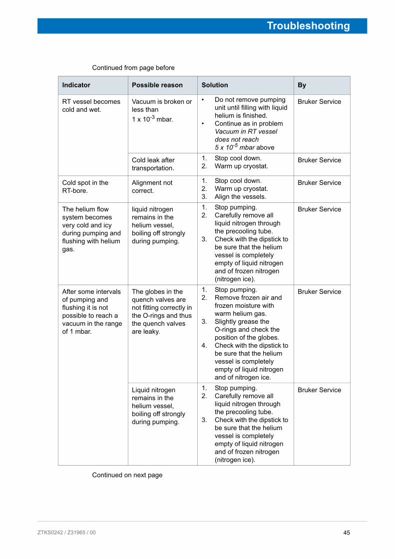
Indicator Possible reason Solution By
RT vessel becomes cold and wet.
Vacuum is broken or less than 1 x 10⁻³ mbar.
• Do not remove pumping unit until filling with liquid helium is finished.
• Continue as in problem Vacuum in RT vessel does not reach 5 x 10⁻⁵ mbar above
Bruker Service
Cold leak after transportation.
1. Stop cool down.2. Warm up cryostat.
Bruker Service
Cold spot in the RT-bore.
Alignment not correct.
1. Stop cool down.2. Warm up cryostat.3. Align the vessels.
Bruker Service
The helium flow system becomes very cold and icy during pumping and flushing with helium gas.
liquid nitrogen remains in the helium vessel, boiling off strongly during pumping.
1. Stop pumping.2. Carefully remove all
liquid nitrogen through the precooling tube.
3. Check with the dipstick to be sure that the helium vessel is completely empty of liquid nitrogen and of frozen nitrogen (nitrogen ice).
Bruker Service
After some intervals of pumping and flushing it is not possible to reach a vacuum in the range of 1 mbar.
The globes in the quench valves are not fitting correctly in the O-rings and thus the quench valves are leaky.
1. Stop pumping.2. Remove frozen air and
frozen moisture with warm helium gas.
3. Slightly grease the O-rings and check the position of the globes.
4. Check with the dipstick to be sure that the helium vessel is completely empty of liquid nitrogen and of nitrogen ice.
Bruker Service
Liquid nitrogen remains in the helium vessel, boiling off strongly during pumping.
1. Stop pumping.2. Carefully remove all
liquid nitrogen through the precooling tube.
3. Check with the dipstick to be sure that the helium vessel is completely empty of liquid nitrogen and of frozen nitrogen (nitrogen ice).
Bruker Service
45 242 / Z31965 / 00

Troubleshooting
Continued from page before
Continued on next page
Indicator Possible reason Solution By
Nitrogen ice in the helium vessel.
Pumping intervals during pumping and flushing were too long and remaining nitrogen was boiling off and got frozen.
1. Warm up the magnet coil with warm helium gas through the precooling tube until the whole coil is warmer than 90 K.
2. Repeat pumping and flushing and carefully check with the dipstick to be sure that the helium vessel is completely empty of liquid nitrogen and of frozen nitrogen (nitrogen ice).
Bruker Service
Transfer of liquid helium does not start.
Empty transporta-tion dewar.
Refill or replace transportation dewar.
Bruker Service
The transfer pressure in the transportation dewar is too low.
Increase the transfer pressure.
Bruker Service
The transportation dewar is leaky, there is no transfer pres-sure built up.
Check the transportation dewar for leakage. Re-tighten all connections.
Bruker Service
The siphon or the helium transfer line are blocked with ice.
Check the siphon and helium transfer line for blockages, remove ice with warm helium gas.
Bruker Service
The cool down of the magnet coil does not continue although helium is transferred.
The helium transfer line is defective.
Check the helium transfer line for icing. If there are cold spots visible, replace the helium transfer line.
Bruker Service
The extension is not mounted on the helium transfer line.
Mount the extension piece on the helium transfer line. Check the helium transfer line to be inserted completely into the siphon.
Bruker Service
46 ZTKS0242 / Z31965 / 00

ZTKS0
Troubleshooting
Continued from page before
Indicator Possible reason Solution By
The zero reading of the Helium Level Sensor can not be adjusted at the beginning of cooling down with liquid helium.
The Helium Level Sensor is not connected correctly with the connector in the helium flow system.
Check the connection in the helium fill-in turret between Helium Level Sensor and connector.
Bruker Service
The Helium Level Sensor is defective.
Check the Helium Level Sensor with the 0% calibration plug.
Bruker Service
The helium level does not reach 100% after cooling down.
Empty transporta-tion dewar, helium transfer stopped.
Refill or replace transportation dewar.
Bruker Service
The Helium Level Sensor is disturbed by the transfer line’s extension piece.
1. Stop the liquid helium transfer.
2. Remove the transfer line.3. Measure the helium level
after some minutes without the transfer line.
Bruker Service
After cool down the helium boil off is higher than specified (up to 5 times).
Usual behavior. A few days are necessary for the radiation shields and the insulation to reach scheduled temperatures.
Wait a few days and check helium boil off. The presence of the current lead in the current lead turret during energizing and shimming helps to cool down the radiation shield due to higher helium flow.
Bruker Service
Temperature of the radiation shield decreases too slowly (if TRS > 250 K after pre-cooling with liquid nitrogen)
Cryogenic Refrigera-tor not operating.
Start Cryogenic Refrigerator. Bruker Service
Cryogenic Refrigera-tion operating not correct
See ”During Operation of the Cryogenic Refrigera-tor” on page 73.
Bruker Service
2 days after cool down the TRS is still higher than set value (alarm of CMU)
Cryogenic Refrigera-tor performance not sufficient.
See ”During Operation of the Cryogenic Refrigera-tor” on page 73.
Bruker Service
Alarm default settings of the CMU or MICS not correct.
Check set values (see sepa-rate manual of the CMU and of the MICS)
Bruker Service
Cold head not mounted correctly.
See ”Mounting the Cryo-genic Refrigerator Parts” on page 54.
Bruker Service
47 242 / Z31965 / 00

Troubleshooting
6.2.4 During Energizing and Shimming
Continued on next page
Indicator Possible reason Solution By
The current lead can not be inserted completely into the connector.
The connector is covered with ice. (frozen moisture or nitrogen ice).
Carefully remove the ice with warm helium gas. To remove small ice spots use the dipstick or the precooling tube as tubing for the warm helium gas.
Bruker Service
The shorting plug was not removed.
Remove the shorting plug with the shorting plug tool.
Bruker Service
The orientation of the current lead is not correct.
Turn the current lead carefully until it can be inserted correctly into the connector.
Bruker Service
Main coil heater test fails.
Power Supply defective.
Replace the Power Supply. Bruker Service
Connector or cables defective.
Clean connectors or replace cables if necessary.
Bruker Service
Setting of sense voltage fails.
The main coil heater switch is "OFF".The main coil switch is not opened.
Switch the main coil heater to "ON" and check the main coil heater current to be adjusted correctly.
Bruker Service
The main coil heater current is not correct. The main coil switch is not opened.
Adjust main coil heater current correctly.
Bruker Service
The auxiliary shorting plug is inserted in the current lead turret by mistake and makes a short circuit across the main coil.
Remove the auxiliary shorting plug and insert it in the helium fill-in turret.
Bruker Service
Current lead can not be removed.
The connector is covered with ice (frozen moisture or nitrogen ice).
Carefully remove the ice with warm helium gas over the helium flow system. To remove small ice spots from the connector use the dipstick or the precooling tube as tub-ing for the warm helium gas.
Bruker Service
48 ZTKS0242 / Z31965 / 00
ZTKS0
Troubleshooting
Continued from page before
Continued on next page
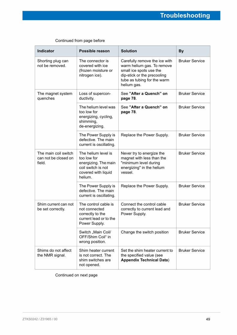
Indicator Possible reason Solution By
Shorting plug can not be removed.
The connector is covered with ice (frozen moisture or nitrogen ice).
Carefully remove the ice with warm helium gas. To remove small ice spots use the dip-stick or the precooling tube as tubing for the warm helium gas.
Bruker Service
The magnet system quenches
Loss of supercon-ductivity.
See ”After a Quench” on page 78.
Bruker Service
The helium level was too low for energizing, cycling, shimming, de-energizing.
See ”After a Quench” on page 78.
Bruker Service
The Power Supply is defective. The main current is oscillating.
Replace the Power Supply. Bruker Service
The main coil switch can not be closed on field.
The helium level is too low for energizing. The main coil switch is not covered with liquid helium.
Never try to energize the magnet with less than the "minimum level during energizing" in the helium vessel.
Bruker Service
The Power Supply is defective. The main current is oscillating.
Replace the Power Supply. Bruker Service
Shim current can not be set correctly.
The control cable is not connected correctly to the current lead or to the Power Supply.
Connect the control cable correctly to current lead and Power Supply.
Bruker Service
Switch „Main Coil/OFF/Shim Coil“ in wrong position.
Change the switch position Bruker Service
Shims do not affect the NMR signal.
Shim heater current is not correct. The shim switches are not opened.
Set the shim heater current to the specified value (see Appendix Technical Data)
Bruker Service
49 242 / Z31965 / 00
Troubleshooting
Continued from page before
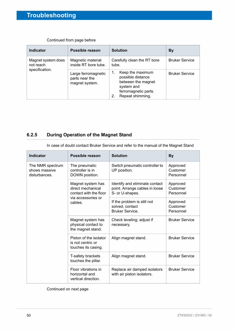
6.2.5 During Operation of the Magnet Stand
In case of doubt contact Bruker Service and refer to the manual of the Magnet Stand
Continued on next page
Indicator Possible reason Solution By
Magnet system does not reach specification.
Magnetic material inside RT bore tube.
Carefully clean the RT bore tube.
Bruker Service
Large ferromagnetic parts near the magnet system.
1. Keep the maximum possible distance between the magnet system and ferromagnetic parts.
2. Repeat shimming.
Bruker Service
Indicator Possible reason Solution By
The NMR spectrum shows massive disturbances.
The pneumatic controller is in DOWN position.
Switch pneumatic controller to UP position.
Approved Customer Personnel
Magnet system has direct mechanical contact with the floor via accessories or cables.
Identify and eliminate contact point. Arrange cables in loose S- or U-shapes.
Approved Customer Personnel
If the problem is still not solved, contact Bruker Service.
Approved Customer Personnel
Magnet system has physical contact to the magnet stand.
Check leveling; adjust if necessary.
Bruker Service
Piston of the isolator is not centric or touches its casing.
Align magnet stand. Bruker Service
T-safety brackets touches the pillar.
Align magnet stand. Bruker Service
Floor vibrations in horizontal and vertical direction.
Replace air damped isolators with air piston isolators.
Bruker Service
50 ZTKS0242 / Z31965 / 00
ZTKS0
Troubleshooting
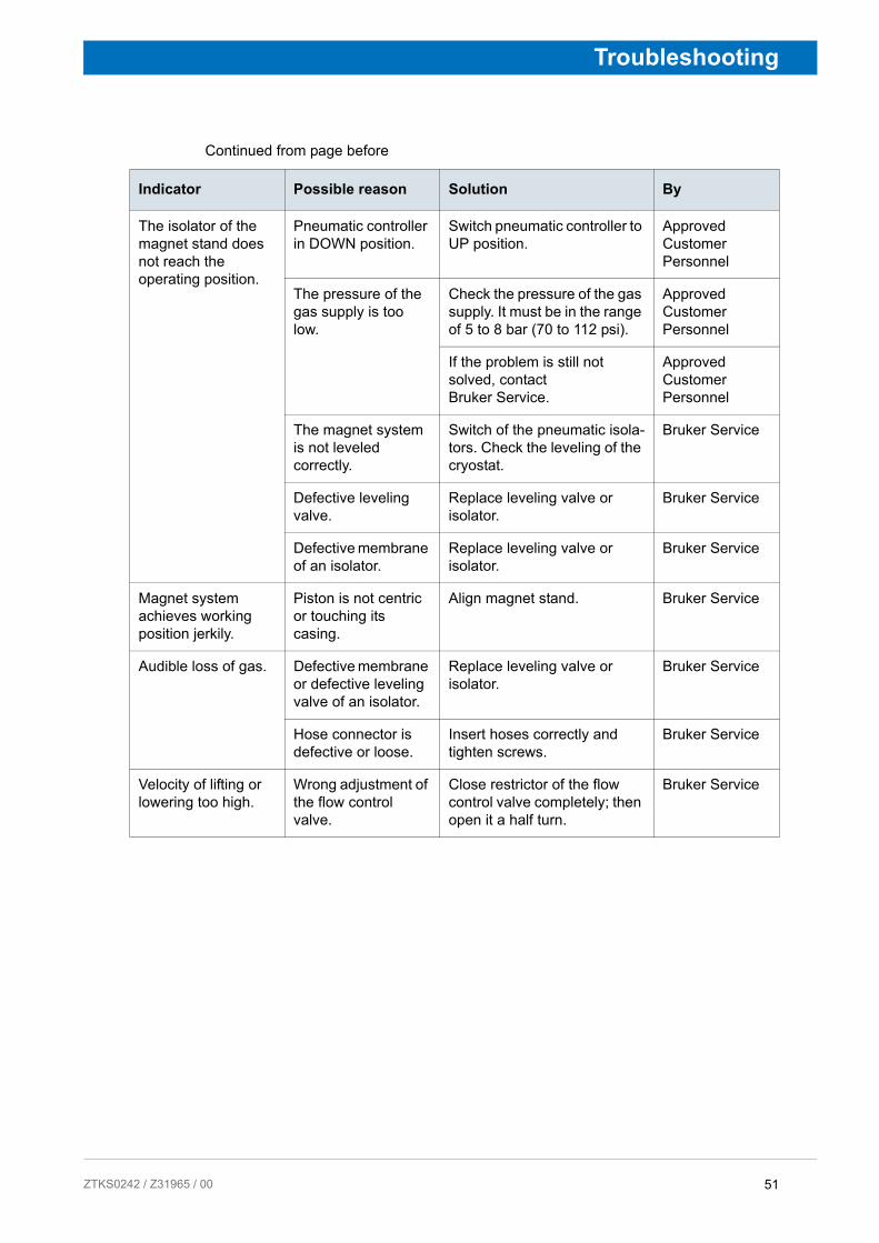
Continued from page before
Indicator Possible reason Solution By
The isolator of the magnet stand does not reach the operating position.
Pneumatic controller in DOWN position.
Switch pneumatic controller to UP position.
Approved Customer Personnel
The pressure of the gas supply is too low.
Check the pressure of the gas supply. It must be in the range of 5 to 8 bar (70 to 112 psi).
Approved Customer Personnel
If the problem is still not solved, contact Bruker Service.
Approved Customer Personnel
The magnet system is not leveled correctly.
Switch of the pneumatic isola-tors. Check the leveling of the cryostat.
Bruker Service
Defective leveling valve.
Replace leveling valve or isolator.
Bruker Service
Defective membrane of an isolator.
Replace leveling valve or isolator.
Bruker Service
Magnet system achieves working position jerkily.
Piston is not centric or touching its casing.
Align magnet stand. Bruker Service
Audible loss of gas. Defective membrane or defective leveling valve of an isolator.
Replace leveling valve or isolator.
Bruker Service
Hose connector is defective or loose.
Insert hoses correctly and tighten screws.
Bruker Service
Velocity of lifting or lowering too high.
Wrong adjustment of the flow control valve.
Close restrictor of the flow control valve completely; then open it a half turn.
Bruker Service
51 242 / Z31965 / 00

Troubleshooting
6.2.6 During Standard Operation
Continued on next page
Indicator Possible reason Solution By
The helium boil off decreases to zero.
The helium flow system is covered with ice.
Contact Bruker Service imme-diately! Do not try to remove ice of the helium flow system!
Approved Customer Personnel
WARNING:
Cryogenic Agents
Quench
The helium flow system or the suspension tubes are blocked with ice.
Blow in warm helium gas carefully through an applicable tube. Do not insert it more than 600 mm from the top of the helium turrets.
Bruker Service
The helium boil off is too high.
The Helium Level Sensor is permanently on (service mode) or used often.
Switch off Helium Level Sensor. Reduce helium level measurement (during measuring of the helium level an amount of helium boils off due to the heat input of the Helium Level Sensor.
Approved Customer Personnel
The atmospheric pressure is decreasing.
Usual behavior. Watch helium boil off daily.
Approved Customer Personnel
If the problem is still not solved, contact Bruker Service.
Approved Customer Personnel
52 ZTKS0242 / Z31965 / 00

ZTKS0
Troubleshooting
Continued from page before
Indicator Possible reason Solution By
Continue of: The helium boil off is too high.
Vacuum reduced. Rebuild vacuum, see ”Rebuilding Vacuum” on page 52
Bruker Service
The radiation baffles are not inserted in the current lead turret.
Insert the radiation baffles into the current lead turret.
Bruker Service
Quench Loss of superconductivity.
See ”After a Quench” on page 78Contact Bruker Service immediately!
Approved Customer Personnel
Cold spots within the RT bore.
Alignment not correct.
Contact Bruker Service. Approved Customer Personnel
RT vessel is wet and cold.
Vacuum reduced. Contact Bruker Service immediately!
Approved Customer Personnel
Not correct helium level warning from MICS GUI.
Helium Level Sensor defective.
Contact Bruker Service immediately!
Approved Customer Personnel
Helium level at constant level, no change during days.
Helium Level Sensor defective.
Contact Bruker Service immediately!
Approved Customer Personnel
WARNING:
Low Temperature
Not correct helium level warning out of MICS GUI.
Helium Level Sensor defective.
Replace Helium Level Sensor (see ”Replacement of the Helium Level Sensor” on page 126)
Bruker Service
Helium level at constant level, no change during days.
Helium Level Sensor defective.
Replace Helium Level Sensor (see ”Replacement of the Helium Level Sensor” on page 126)
Bruker Service
53 242 / Z31965 / 00

Troubleshooting
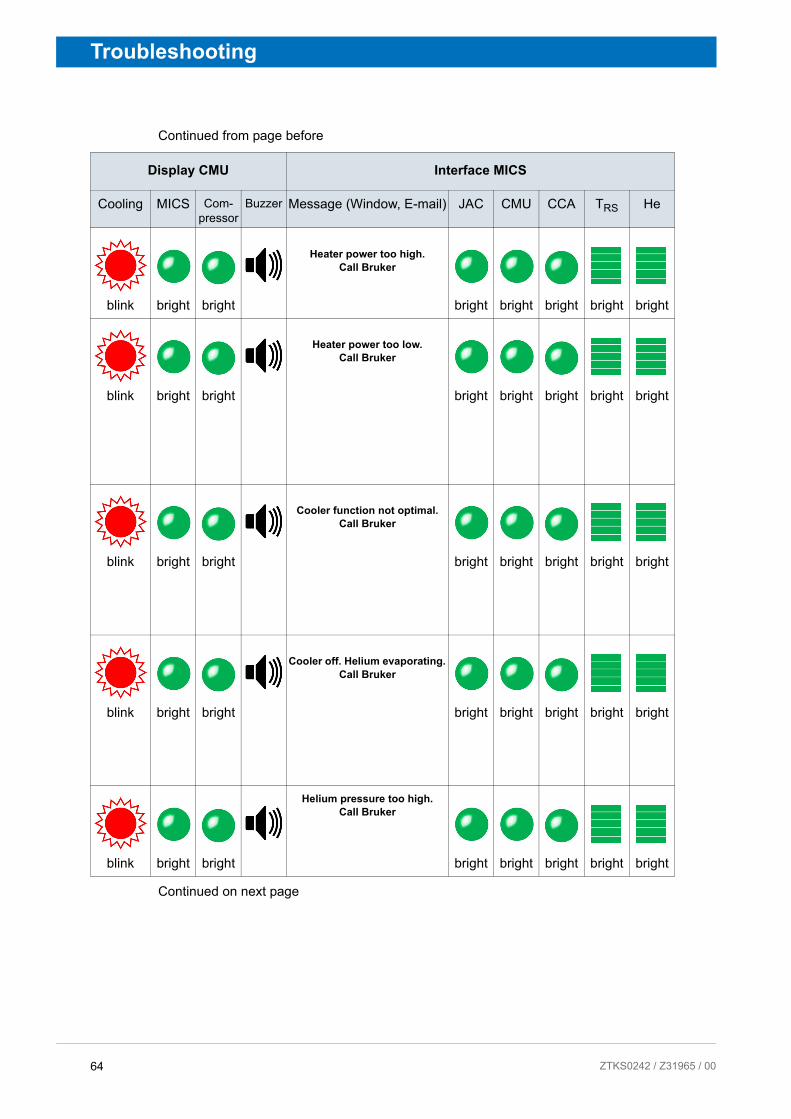
The following information you might find during standard operation of the magnet system. The display and interfaces of CMU and MICS are on the left side, the corresponding reason and solution is in the same row on the right side.
The alert massage given by e-mail gives detailed information on which sensor value is out of limit. For further information refer to the User Manual of MICS.
Continued on next page
Display CMU Interface MICS
Cooling MICS Com-pressor
Buzzer Message (Window, E-mail) JAC CMU CCA TRS He
blink bright bright
Cooler function not optimal. Call Bruker
bright bright bright bright bright
blink bright bright
Cooler function not optimal. Call Bruker
bright bright bright bright bright
blink bright bright
Cooler function not optimal. Call Bruker
bright bright bright bright bright
54 ZTKS0242 / Z31965 / 00
ZTKS0
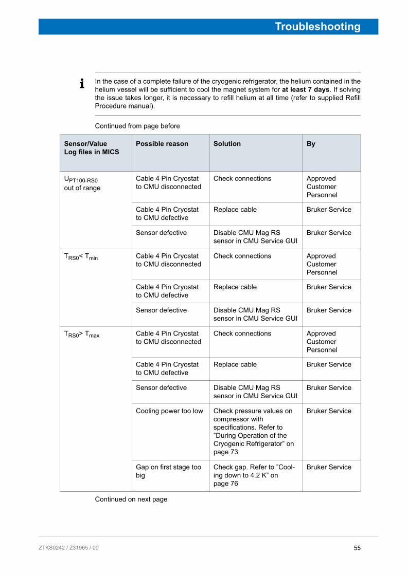
Troubleshooting
i In the case of a complete failure of the cryogenic refrigerator, the helium contained in the helium vessel will be sufficient to cool the magnet system for at least 7 days. If solving the issue takes longer, it is necessary to refill helium at all time (refer to supplied Refill Procedure manual).
Continued from page before
Continued on next page
Sensor/Value Log files in MICS
Possible reason Solution By
UPT100-RS0 out of range
Cable 4 Pin Cryostat to CMU disconnected
Check connections Approved Customer Personnel
Cable 4 Pin Cryostat to CMU defective
Replace cable Bruker Service
Sensor defective Disable CMU Mag RS sensor in CMU Service GUI
Bruker Service
TRS0< Tmin Cable 4 Pin Cryostat to CMU disconnected
Check connections Approved Customer Personnel
Cable 4 Pin Cryostat to CMU defective
Replace cable Bruker Service
Sensor defective Disable CMU Mag RS sensor in CMU Service GUI
Bruker Service
TRS0> Tmax Cable 4 Pin Cryostat to CMU disconnected
Check connections Approved Customer Personnel
Cable 4 Pin Cryostat to CMU defective
Replace cable Bruker Service
Sensor defective Disable CMU Mag RS sensor in CMU Service GUI
Bruker Service
Cooling power too low Check pressure values on compressor with specifications. Refer to ”During Operation of the Cryogenic Refrigerator” on page 73
Bruker Service
Gap on first stage too big
Check gap. Refer to ”Cool-ing down to 4.2 K” on page 76
Bruker Service
55 242 / Z31965 / 00

Troubleshooting
Continued from page before
Continued on next page
Display CMU Interface MICS
Cooling MICS Com-pressor
Buzzer Message (Window, E-mail) JAC CMU CCA TRS He
blink bright bright
Cooler function not optimal. Check system status
bright bright bright bright bright
blink bright bright
Cooler function not optimal. Call Bruker
bright bright bright bright bright
blink bright bright
Cooler function not optimal. Call Bruker
bright bright bright bright bright
56 ZTKS0242 / Z31965 / 00

ZTKS0
Troubleshooting
Continued from page before
Continued on next page
Sensor/Value Log files in MICS
Possible reason Solution By
UPT100 RS1 out of range
Cable 4 Pin Cryostat to BSMS Mag RS disconnected
Check connections Approved Customer Personnel
BSMS Mag RS cable defective
Replace cable Bruker Service
BSMS Mag RS defective
Replace BSMS Mag RS box
Bruker Service
Sensor defective Disable sensor in CMU Service GUI
Bruker Service
TRS1< Tmin Cable 4 Pin Cryostat to VTA Mag RS disconnected
Check connections Approved Customer Personnel
Mag RS box cable defective
Replace Mag RS box cable Bruker Service
Mag RS box defective Replace Mag RS box Bruker Service
Sensor defective Disable sensor in CMU Service GUI
Bruker Service
TRS1> Tmax Cable 4 Pin Cryostat to VTA Mag RS disconnected
Check connections Approved Customer Personnel
Cable 4 Pin Cryostat to Mag RS Box defective
Replace cable Bruker Service
Sensor defective Disable BSMS Mag RS in CMU Service GUI
Bruker Service
Cooling power too low Check pressure values on compressor with specifications. Refer to ”During Operation of the Cryogenic Refrigerator” on page 73
Bruker Service
Gap on first stage too big
Check gap. Refer to ”Cool-ing down to 4.2 K” on page 76
Bruker Service
57 242 / Z31965 / 00

Troubleshooting
Continued from page before
Continued on next page
Display CMU Interface MICS
Cooling MICS Com-pressor
Buzzer Message (Window, E-mail) JAC CMU CCA TRS He
blink bright bright
Helium measurement failed. Check system status
bright bright bright bright bright
blink bright blink
Compressor off.Check compressor status
bright bright bright bright bright
58 ZTKS0242 / Z31965 / 00

ZTKS0
Troubleshooting
Continued from page before
Continued on next page
Sensor/Value Log files in MICS
Possible reason Solution By
UHe-Sensor out of range
Cable from helium sensor to console disconnected
Check connections Approved Customer Personnel
Electronic failure Check helium log file Approved Customer Personnel
Calibration missing Calibrate helium sensor in MICS GUI
Bruker Service
Cable from sensor to console defective
Replace cable Bruker Service
Helium sensor defective
Replace helium sensor Bruker Service
Compressor off Compressor power supply failure
Check connections Approved Customer Personnel
Cooling water failure Check water chiller Bruker Service
Compressor not operating
Check compressor. Refer to the manual of the cryogenic refrigerator
Bruker Service
59 242 / Z31965 / 00

Troubleshooting
Continued from page before
Continued on next page
Display CMU Interface MICS
Cooling MICS Com-pressor
Buzzer Message (Window, E-mail) JAC CMU CCA TRS He
blink bright blink
Compressor function not optimal.
Call Bruker
bright bright bright bright bright
blink bright blink
Cooling water temperature too high. Check chiller
bright bright bright bright bright
blink bright blink
Compressor function not optimal.
Call Bruker
bright bright bright bright bright
blink bright blink
Cooling water flow too low. Check chiller
bright bright bright bright bright
bright bright bright
CMU e-mail problem.Check settings/connection
bright bright bright bright bright
-/- -/- -/- Cooler funktion not optimal. Call Bruker
bright bright bright bright bright
60 ZTKS0242 / Z31965 / 00

ZTKS0
Troubleshooting
Continued from page before
Continued on next page
Sensor/Value Log files in MICS
Possible reason Solution By
UT, Cooling Water out of range
Cable at CCA or CMU disconnected
Check connections Approved Customer Personnel
CCA cable or CCA defective
Replace CCA cable or CCA Bruker Service
TCooling Water > Tmax Cooling water problem Check chiller loop Approved Customer Personnel
UQ, Cooling Water out of range
Cable at CCA or CMU disconnected
Check connections Approved Customer Personnel
CCA cable or CCA defective
Replace CCA cable or CCA Bruker Service
QChiller < Qmin Cooling water problem Check chiller loop Approved Customer Personnel
JAC can not send e-mail
E-mail setting incorrect Check settings Approved Customer Personnel
LAN cable disconnected
Check LAN connections Approved Customer Personnel
JAC internal error JAC defective Reboot JAC. If not solved, replace JAC.
Bruker Service
61 242 / Z31965 / 00

Troubleshooting
Continued from page before
Continued on next page
Display CMU Interface MICS
Cooling MICS Com-pressor
Buzzer Message (Window, E-mail) JAC CMU CCA TRS He
-/- -/- -/- Power failure. RZ system off
bright bright bright bright bright
-/- -/- -/- Connection to JAC failed. Check system status
Remarks: compressor switched off to avoid underpressure
bright bright bright bright bright
blink bright bright
Connection to BSMS failed. Check BSMS status
bright bright bright bright bright
blink bright bright
Cooler function not optimal. Check system status
bright bright bright bright bright
62 ZTKS0242 / Z31965 / 00
ZTKS0
Troubleshooting
Continued from page before
Continued on next page
Sensor/Value Log files in MICS
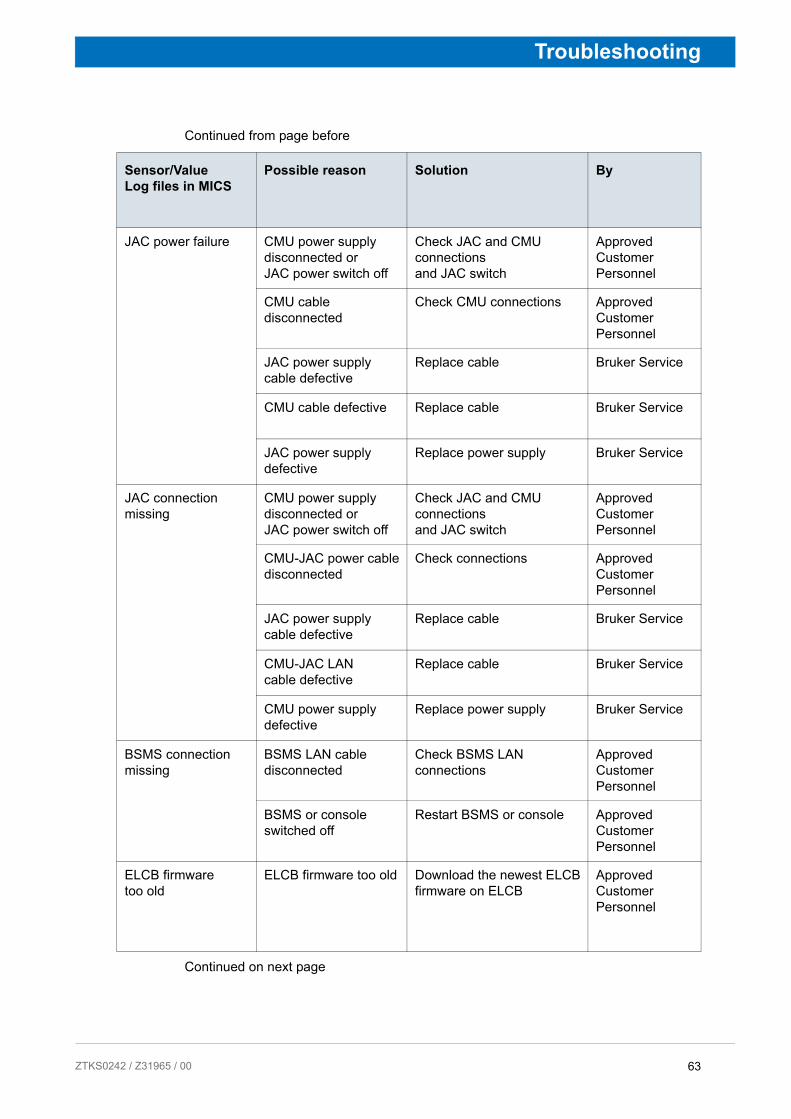
Possible reason Solution By
JAC power failure CMU power supply disconnected or JAC power switch off
Check JAC and CMU connections and JAC switch
Approved Customer Personnel
CMU cable disconnected
Check CMU connections Approved Customer Personnel
JAC power supply cable defective
Replace cable Bruker Service
CMU cable defective Replace cable Bruker Service
JAC power supply defective
Replace power supply Bruker Service
JAC connection missing
CMU power supply disconnected or JAC power switch off
Check JAC and CMU connections and JAC switch
Approved Customer Personnel
CMU-JAC power cable disconnected
Check connections Approved Customer Personnel
JAC power supply cable defective
Replace cable Bruker Service
CMU-JAC LAN cable defective
Replace cable Bruker Service
CMU power supply defective
Replace power supply Bruker Service
BSMS connection missing
BSMS LAN cable disconnected
Check BSMS LAN connections
Approved Customer Personnel
BSMS or console switched off
Restart BSMS or console Approved Customer Personnel
ELCB firmware too old
ELCB firmware too old Download the newest ELCB firmware on ELCB
Approved Customer Personnel
63 242 / Z31965 / 00
Troubleshooting
Continued from page before
Continued on next page
Display CMU Interface MICS
Cooling MICS Com-pressor
Buzzer Message (Window, E-mail) JAC CMU CCA TRS He
blink bright bright
Heater power too high.Call Bruker
bright bright bright bright bright
blink bright bright
Heater power too low.Call Bruker
bright bright bright bright bright
blink bright bright
Cooler function not optimal.Call Bruker
bright bright bright bright bright
blink bright bright
Cooler off. Helium evaporating. Call Bruker
bright bright bright bright bright
blink bright bright
Helium pressure too high. Call Bruker
bright bright bright bright bright
64 ZTKS0242 / Z31965 / 00

ZTKS0
Troubleshooting
Continued from page before
Continued on next page
Sensor/Value Log files in MICS
Possible reason Solution By
Heater power above set value
Pressure is below set value
Check for leaks in the helium flow system
Bruker Service
Pressure can not be reached due to leak
Check for leaks in the helium flow system
Bruker Service
Heater power below set value
Gas pressure inside compressor too low
Check gas pressure values of the compressor. Refill helium if not correct.
Bruker Service
Rotary valve defective Check operation status of the rotary valve. Replace rotary valve if necessary
Bruker Service
Cold head power too low
Replace cold head Bruker Service
Helium pressure below set value
Cable from pressure sensor to CMU disconnected
Check connections Approved Customer Personnel
CMU controller defective
Replace CMU Bruker Service
Heater defective Check heater resistance. If broken replace heater
Bruker Service
Helium pressure below lowest limit
Cable from pressure sensor to CMU disconnected
Check connections Approved Customer Personnel
CMU controller defective
Replace CMU Bruker Service
Heater defective Check heater resistance. If broken replace heater
Bruker Service
Helium pressure above set value
Cooling power too low. Check heater power. If zero, refer to Heater power < 50 mW
Bruker Service
65 242 / Z31965 / 00

Troubleshooting
Continued from page before
Continued on next page
Display CMU Interface MICS
Cooling MICS Com-pressor
Buzzer Message (Window, E-mail) JAC CMU CCA TRS He
blink bright bright
Cooler off. Helium evaporating. Call Bruker
Remarks: compressor switched off to avoid underpressure
after 15 minbright bright bright bright bright
-/- -/- -/- Connection to CMU failed. Check CMU status
Remarks: compressor switched off to avoid underpressure
after 15 minbright bright bright bright bright
blink bright blink
Connection to CCA failed. Check CCA status
Remarks: compressor switched off to avoid underpressure
after 15 minbright bright bright bright bright
blink blink bright
No message -/- -/- -/- -/- -/-
66 ZTKS0242 / Z31965 / 00

ZTKS0
Troubleshooting
Continued from page before
Continued on next page
Sensor/Value Log files in MICS
Possible reason Solution By
Pressure out of range Cable from pressure sensor to CMU disconnected
Check connections Approved Customer Personnel
Pressure sensor defective
Replace pressure sensor Bruker Service
CMU off CMU cable disconnected
Check connections Approved Customer Personnel
CMU cable defective Replace CMU cable Bruker Service
CMU defective Replace CMU Bruker Service
CCA off CCA cable disconnected
Check connections Approved Customer Personnel
CCA cable defective Replace CCA cable Bruker Service
CCA defective Replace CCA Bruker Service
MICS or PC off Console workstation down
Restart workstation Approved Customer Personnel
MICS software not running
Restart MICS. MICS has to run at all time
Approved Customer Personnel
67 242 / Z31965 / 00
Troubleshooting
Continued from page before
Continued on next page
Display CMU Interface MICS
Cooling MICS Com-pressor
Buzzer Message (Window, E-mail) JAC CMU CCA TRS He
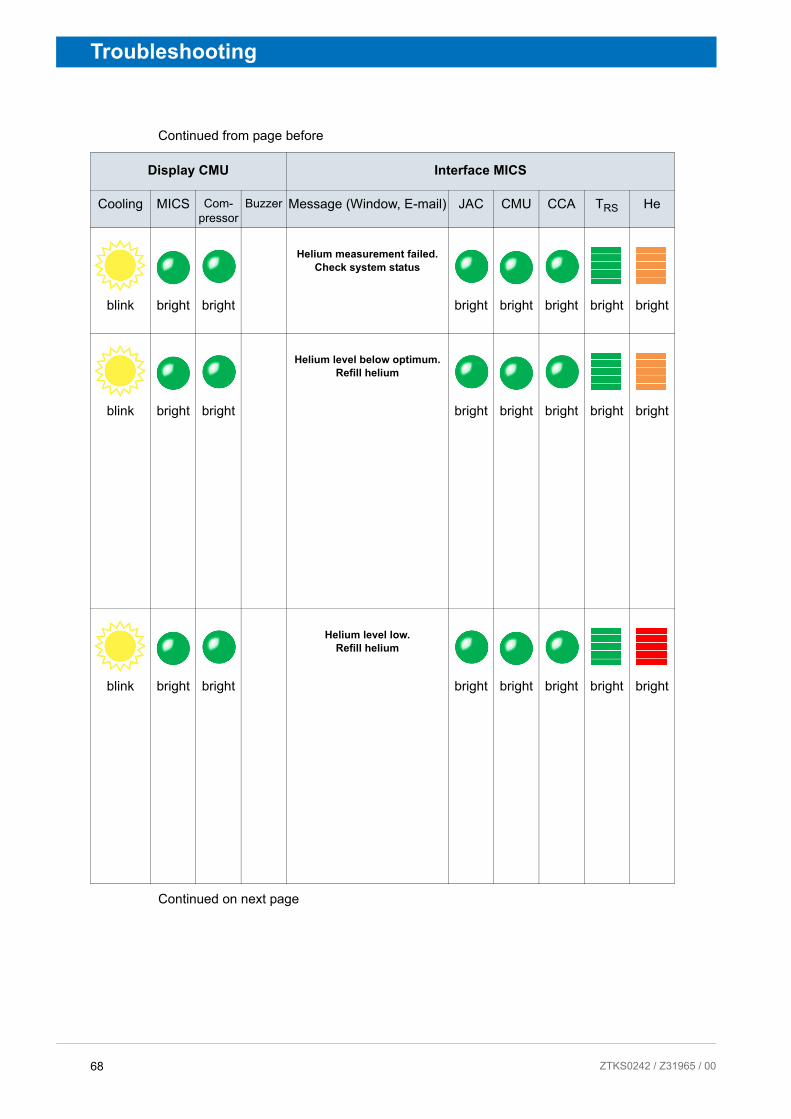
blink bright bright
Helium measurement failed. Check system status
bright bright bright bright bright
blink bright bright
Helium level below optimum. Refill helium
bright bright bright bright bright
blink bright bright
Helium level low. Refill helium
bright bright bright bright bright
68 ZTKS0242 / Z31965 / 00

ZTKS0
Troubleshooting
Continued from page before
Continued on next page
Sensor/Value Log files in MICS
Possible reason Solution By
Data update missing Cable from helium sensor disconnected
Check connections Approved Customer Personnel
Calibration missing Calibrate helium sensor in MICS GUI
Bruker Service
He-Level < 85 % Helium leak Refill helium. Call Bruker Approved Customer Personnel
Cooling power too low. Check pressure values on compressor with specifications. Refer to ”During Operation of the Cryogenic Refrigerator” on page 73
Bruker Service
Rotary valve defective Check operation status of the rotary valve. Replace rotary valve if necessary
Bruker Service
Cold head power too low
Replace cold head Bruker Service
He-Level < 70 % Helium leak Refill helium. Call Bruker Approved Customer Personnel
Cooling power too low. Check pressure values on compressor with specifications. Refer to ”During Operation of the Cryogenic Refrigerator” on page 73
Bruker Service
Rotary valve defective Check operation status of the rotary valve. Replace rotary valve if necessary
Bruker Service
Cold head power too low
Replace cold head Bruker Service
69 242 / Z31965 / 00

Troubleshooting
Continued from page before
Continued on next page
Display CMU Interface MICS
Cooling MICS Com-pressor
Buzzer Message (Window, E-mail) JAC CMU CCA TRS He
blink bright bright
Helium level too low. Refill helium
bright bright bright bright bright
70 ZTKS0242 / Z31965 / 00

ZTKS0
Troubleshooting
Continued from page before
Sensor/Value Log files in MICS
Possible reason Solution By
He-Level < 40 % Helium leak Refill helium. Call Bruker immediately.
Approved Customer Personnel
Cooling power too low. Check pressure values on compressor with specifications. Refer to ”During Operation of the Cryogenic Refrigerator” on page 73
Bruker Service
Rotary valve defective Check operation status of the rotary valve. Replace rotary valve if necessary
Bruker Service
Cold head power too low
Replace cold head Bruker Service
71 242 / Z31965 / 00

Troubleshooting
6.2.7 During De-energizing and Warming up
Indicator Possible reason Solution By
The magnet system quenches during de-energizing.
The helium level was too low for de-energizing.
Refill helium at least to the minimum allowed level (see Appendix Technical Data).
Bruker Service
The Power Supply is defective.
Replace Power Supply. Bruker Service
The main current is oscillating.
Replace Power Supply. Bruker Service
The shim current can not be set correctly.
The control cable is not connected correctly to the current lead and/or the Power Supply.
Connect the control cable to the current lead and to the Power Supply correctly.
Bruker Service
The switch "Main Coil/OFF/Shim Coil" is not on the "Shim Coil" position.
Switch "Main Coil/OFF/Shim Coil" on the "Shim Coil" position.
Bruker Service
High helium flow after breaking vacuum.
Remaining cryogenic agents in the inner vessels.
Remove liquid helium. Bruker Service
Vacuum still remains after 12 hours.
Vacuum Valve is closed.
Open Vacuum Valve. Block it if necessary.
Bruker Service
RT vessel is wet and cold.
Cryostat is still cold. Wait until RT vessel is dry and warm. Check PT 100 temperature sensors.
Bruker Service
RT bore wet and cold before disassembling.
Cryostat is still cold. Wait one more day.Do not open a cryostat before the room temperature bore tube is warm and dry!
Bruker Service
72 ZTKS0242 / Z31965 / 00

ZTKS0
Troubleshooting
6.2.8 During Operation of the Cryogenic Refrigerator
i In the case of a complete failure of the Cryogenic Refrigerator, the helium contained in the helium vessel will be sufficient to cool the magnet for at least 3 days. If solving the issue takes longer, it is necessary to refill helium at all time (refer to supplied Refilling Procedure).
i In case of any issue or failure specified in the following table where the intervention of the operator is necessary, make sure the start button of the compressor is switched off and the power supply of the compressor is disconnected. After resolving the issue, connect the power supply and push the start button of the compressor. If the compressor does not start immediately, press the temperature and the pressure switch for reset and after this the start button on the compressor. For problems not specified in this chapter refer to the supplied manual of the Cryogenic Refrigerator.
Continued on next page
Indicator Possible reason Solution By
Compressor is not operating.
No power supply or power supply interrupted.
Check the power supply to the compressor and verify that it meets the system requirements.
Approved Customer Personnel
Circuit breaker OFF. Check that the circuit breaker on the front panel of the compressor is ON.Check for possible causes why the circuit breaker switched off.
Approved Customer Personnel
Check for possible causes why the circuit breaker switched off.
Approved Customer Personnel
Pressure switch tripped
Reset the pressure switch located at the bottom of the front panel of the compressor.
Approved Customer Personnel
Temperature switchtripped
Reset the temperature switch located at the bottom of the front panel of the compressor.
Approved Customer Personnel
73 242 / Z31965 / 00
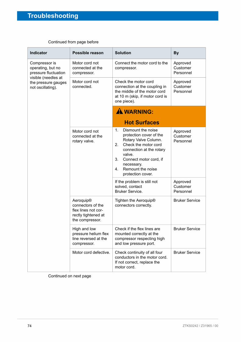
Troubleshooting
Continued from page before
Continued on next page
Indicator Possible reason Solution By
Compressor is operating, but no pressure fluctuation visible (needles at the pressure gauges not oscillating).
Motor cord not connected at the compressor.
Connect the motor cord to the compressor.
Approved Customer Personnel
Motor cord not connected.
Check the motor cord connection at the coupling in the middle of the motor cord at 10 m (skip, if motor cord is one piece).
Approved Customer Personnel
WARNING:
Hot Surfaces
Motor cord not connected at the rotary valve.
1. Dismount the noise protection cover of the Rotary Valve Column.
2. Check the motor cord connection at the rotary valve.
3. Connect motor cord, if necessary.
4. Remount the noise protection cover.
Approved Customer Personnel
If the problem is still not solved, contact Bruker Service.
Approved Customer Personnel
Aeroquip® connectors of the flex lines not cor-rectly tightened at the compressor.
Tighten the Aeroquip® connectors correctly.
Bruker Service
High and low pressure helium flex line reversed at the compressor.
Check if the flex lines are mounted correctly at the compressor respecting high and low pressure port.
Bruker Service
Motor cord defective. Check continuity of all four conductors in the motor cord. If not correct, replace the motor cord.
Bruker Service
74 ZTKS0242 / Z31965 / 00

ZTKS0
Troubleshooting
Continued from page before
Continued on next page
Indicator Possible reason Solution By
Continue of: Compressor is operating, but no pressure fluctuation visible (needles at the pressure gauges not oscillating).
Aeroquip® conectors of the flex lines tightened not correctly at the rotary valve.
Tighten the Aeroquip® connectors correctly.
Bruker Service
High and low pressure helium flex line reversed at the rotary valve.
Check if the flex lines are mounted correctly at the rotary valve respecting high and low pressure port.
Bruker Service
Rotary valve is defective.
If possible, check if the rotary valve sound has changed since installation. If the typical sound is missing, the rotary valve might be defective and has to be exchanged.Replace the rotary valve.
Bruker Service
Compressor is operating, pressure fluctuation visible at the pressure gauges, extinguish short after start.
Water chiller not running.
Check possible reasons why the water cooler is not running. Start the water cooler.
Approved Customer Personnel
Cooling water flow too low.
Check cooling water supply is sufficient (refer to supplied manual of the Cryogenic Refrigerator).
Approved Customer Personnel
Cooling water flow too low due to icing, blockage, fouling or leak in the cooling water lines.
Search possible reason for the disturbance.Check the cooling water supply is as specified in the supplied manual of the Cryogenic Refrigerator and the manual of the water chiller.
Approved Customer Personnel
Not correct environ-mental temperature (too high or too low).
Check the environmental temperature is as specified.
Approved Customer Personnel
Not correct water temperature (too high or too low).
Check the cooling water temperature is as specified.
Approved Customer Personnel
75 242 / Z31965 / 00

Troubleshooting
Continued from page before
Continued on next page
Indicator Possible reason Solution By
Compressor is operating, cryogenic refrigeration not sufficient.
Exclude all previous reasons of this list.
Approved Customer Personnel
Not correct maintenance.
Check periodic maintenance work was made according to schedule (see ”Maintenance Timetable” on page 84).
Approved Customer Personnel
If the problem is still not solved, contact Bruker Service.
Approved Customer Personnel
WARNING:
Hot Surfaces
Connecting line between rotary valve and cold head not mounted correctly at the cold head.
Tighten the Aeroquip® connectors correctly. Check if the O-rings of the fitting are in correct position (see chapter ”Mounting the Rotary Valve and Flex Lines” on page 60).
Bruker Service
Low helium pressure inside the compressor helium circuit.
Recharge helium of high purity (He 5.0, 99.999%). Refer to supplied manual of the Cryogenic Refrigerator.
Bruker Service
Low helium pressure due to small leak inside the compressor helium circuit.
1. Leak detection with leak detector at connectors, flex lines, inside com-pressor, cold head, rotary valve, connecting line.
2. Eliminate leak, if possible.
3. Recharge helium of high purity (He 5.0, 99.999%). Refer to supplied manual of the Cryogenic Refrigerator.
Bruker Service
High helium pressure inside the compressor.
Vent helium to the set value. Refer to supplied manual of the Cryogenic Refrigerator.
Bruker Service
76 ZTKS0242 / Z31965 / 00

ZTKS0
Troubleshooting
Continued from page before
Indicator Possible reason Solution By
Continue of: Compressor is operating, cryogenic refrigeration not sufficient.
Cold head contaminated.
Remount the cold head. Pump and flush the cold head. See chapter ”Proce-dure in case of Cryogenic Refrigerator failure” on page 81
Bruker Service
Cold head defective. Replace the cold head. See chapter ”Procedure in case of Cryogenic Refrigerator failure” on page 81
Bruker Service
Cryogenic Refrig-erator contaminated.
Replace the complete Cryogenic Refrigerator. See chapter ”Procedure in case of Cryogenic Refrigerator failure” on page 81 and ”Mounting the Cryogenic Refrigerator Parts” on page 53.
Bruker Service
77 242 / Z31965 / 00

Troubleshooting
6.3 Troubleshooting Work
6.3.1 After a Quench
Quench while in persistent mode:
1. Wait until the quench valves are closed and no helium evaporate out of the quench valves.
2. Wait until there is no helium vapor visible in the room or the ceiling to make sure there is sufficient oxygen in the room.
3. Switch off the alarm at the CMU.
4. Check the globes in the quench valves for their correct position.
5. Remove probe and shim system to prevent icing from the shim system.
6. Start the refill with liquid helium as soon as possible after the quench (within one hour after the quench; refer to the supplied Refilling Procedure).
7. Contact Bruker Service immediately.
Figure 6.1: Quench picture
A quench is the very fast de-energizing of the magnet by loss of its superconductivity. The stored magnetic energy is converted into heat, which promotes rapid evapora-tion of large quantities of helium. After an appearance of a quench contact Bruker Service immediately.
WARNING
Cryogenic Agents (see page 21)
Quench (see page 22)
78 ZTKS0242 / Z31965 / 00

ZTKS0
Troubleshooting
i If the quench occurs unattended or helium transfer was not possible within one hour after the quench, it is recommended to warm up the system to 90 K.
79 242 / Z31965 / 00

Troubleshooting
6.3.2 Procedure in case of an alarm signal
If the temperature of the radiation shield, the heater power or pressure inside the helium vessel exceeds the set maximum allowed values, an alarm will warn the operator (audible from the CMU, visible at the display of the CMU and the console via MICS).
Follow this procedure to fix the issue before contacting Bruker Service.
Note:
• Date and time.
• Temperature given on the display of the MICS.
• Turn the alarm of the CMU off.
• Which errors or warnings appear?
• What are the readings of the pressure gauges, run time counter etc. of the compressor?
• Which parts seems to be ok/not ok?
• How did the failure occur and what happened before failure?
80 ZTKS0242 / Z31965 / 00

ZTKS0
Troubleshooting
6.3.3 Procedure in case of Cryogenic Refrigerator failure
In case of a failure of the Cryogenic Refrigerator the temperature of the shield TRS will slowly rise to 200 K and the helium boil off to 1000 ml/h. This is usual behavior.
In case of failure shorter than 7 days just restart the compressor of the Cryogenic Refrigerator. See remarks at chapter ”During Operation of the Cryogenic Refrigera-tor” on page 73 for further information.
After restarting the Cryogenic Refrigerator, at least two days are necessary to recover the previous state of the magnet system. If the temperature and helium boil off does not decrease in the next two days call Bruker Service.
Figure 6.2: Temperature profile during Cryogenic Refrigerator failure
81 242 / Z31965 / 00

Troubleshooting
82 ZTKS0242 / Z31965 / 00

ZTKS0
7 Maintenance
Maintenance must be performed only with approved qualification.
In case of doubt contact Bruker Service. For contact information see page 9 of this document.
7.1 Safety
Approved Persons
Bruker Service, Approved Customer Personnel
Personal protective equipment
Protective goggles
Protective gloves
Safety shoes
WARNING
Magnetic Fields (see page 20)
Cryogenic Agents (see page 21)
Electricity (see page 21)
Gas under Pressure (see page 21)
Low Temperatures (see page 23)
Spontaneous Ignition and Explosion (see page 23)
Hot Surfaces (see page 25)
83242 / Z31965 / 00

Maintenance
7.2 Cleaning
Procedure
• Clean the RT vessel of the magnet system, the magnet stand with dry or slightly damp cloth.
• Only use water and neutral detergents.
• Do not use volatile cleaning solvents.
7.3 Maintenance Timetable
Continued on next page
Interval Device Work By
daily Cryostat Check the helium flow. Approved Customer Personnel
4.500 h(0.5 year)
Cryogenic Refrigerator
• Check the values at the high and low pressure gauges on the front panel of the compressor if the mean values are different and if an oscillation of the needles is noticeable. Refer to the supplied manual of the Cryogenic Refrig-erator. Contact Bruker Service if values are different.
• Check the proper operation of the water cooling unit.
• Check system pressure, water flow and temperatures. Refer to the manual of the water cooling unit for further information.
Approved Customer Personnel
Table 7.1: Maintenance Timetable - part 1
84 ZTKS0242 / Z31965 / 00

ZTKS0
Maintenance
Continued from page before
Interval Device Work By
17.500 hours (2 years)
Cryogenic Refrigerator
• Replace the rotary valve. Refer to chapter ”Replacement of the Rotary Valve and the Cold Head” on page 7-136.
• Replace the adsorber of the compressor. Refer to the supplied manual of the Cryogenic Refrig-erator.
• Check the values at the high and low pressure gauges on the front panel of the compressor if the mean values are different and if an oscillation of the needles is noticeable. Refer to the supplied manual of the Cryogenic Refrig-erator. - Pressure to high: Vent helium gas. Use the Service Kit. - Pressure to low: Refill helium gas of high purity (He 5.0, 99.999%). Use the Service Kit.
Bruker Service
35.000 hours (4 years)
Cryogenic Refrigerator
• Replace rotary valve and cold head. Refer to chapter ”Replace-ment of the Rotary Valve and the Cold Head” on page 7-136.
• Replace the compressor.
Bruker Service
Table 7.2: Maintenance Timetable - part 2
85 242 / Z31965 / 00

Maintenance
7.4 Maintenance Work at the Cryogenic Refrigerator
Approved Persons: Bruker Service only
86 ZTKS0242 / Z31965 / 00

ZTKS0
8 Disassembling
8.1 Safety
Approved Persons: Bruker Service only
87242 / Z31965 / 00

Disassembling
88 ZTKS0242 / Z31965 / 00
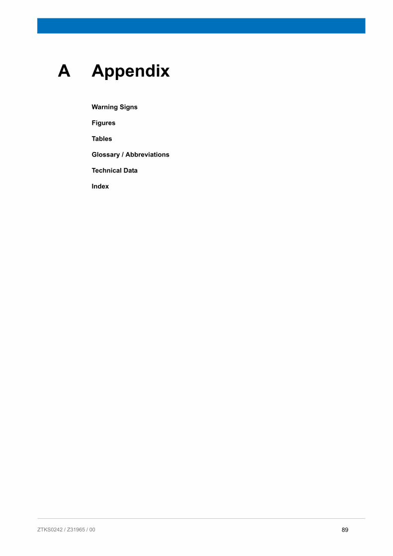
ZTKS0
A Appendix
Warning Signs
Figures
Tables
Glossary / Abbreviations
Technical Data
Index
89242 / Z31965 / 00

Appendix
90 ZTKS0242 / Z31965 / 00

ZTKS0
Appendix
A.1 Warning Signs
Danger
Key Word and Symbol .................................................................................. 17
Warning
Cryogenic Agents .......................................................................................... 21Electricity ....................................................................................................... 21Gas under Pressure ...................................................................................... 22Heavy Weights .............................................................................................. 24Intended Use ................................................................................................. 18Key Word and Symbol .................................................................................. 17Low Temperatures ........................................................................................ 23Magnetic Field ............................................................................................... 20Persons ......................................................................................................... 18Quench ......................................................................................................... 22Safety Devices .............................................................................................. 19Signs and Labels .......................................................................................... 20Slippage ........................................................................................................ 23Spare Parts ................................................................................................... 19Spontaneous Ignition and Explosion ............................................................. 23
Caution
Incorrect Transportation ................................................................................ 25Key Word and Symbol .................................................................................. 17
Notice
Key Word and Symbol .................................................................................. 17
91 242 / Z31965 / 00

Appendix
92 ZTKS0242 / Z31965 / 00

ZTKS0
Appendix
A.2 Figures
Figure 1.1: General view a Magnet System with Aeon /RZ Cryostat ..................... 12
Figure 2.1: Safety Devices of the RZ Cryostat....................................................... 28
Figure 3.1: Packaging (without surrounding panels).............................................. 31
Figure 3.2: Transportation by forklift - front side .................................................... 33
Figure 3.3: Transportation by forklift - rear side ..................................................... 33
Figure 3.4: Attachment points for lifting equipment................................................ 34
Figure 3.5: Instruction label for lifting equipment ................................................... 34
Figure 5.1: Start the Magnet Stand ........................................................................ 40
Figure 5.2: Stop the Magnet Stand ........................................................................ 40
Figure 6.1: Quench picture..................................................................................... 78
Figure 6.2: Temperature profile during Cryogenic Refrigerator failure................... 81
Figure A.1: Dimension Cryostat - Front View ....................................................... 100
Figure A.2: Dimension Cryostat - Top View ......................................................... 102
Figure A.3: Helium Level Graph ........................................................................... 104
Figure A.4: Helium Level Sensor.......................................................................... 105
Figure A.5: Characteristic Curve PT 100.............................................................. 106
Figure A.6: Characteristic Curve IBT.................................................................... 107
Figure A.7: Wiring Diagramm Temperature Sensors ........................................... 108
Figure A.8: Fringe field plot .................................................................................. 110
Figure A.9: Current Lead 55 pins ......................................................................... 111
Figure A.10: Wiring Diagram Magnet ..................................................................... 112
Figure A.11: Wiring Diagram Magnet - Control ...................................................... 113
Figure A.12: Wiring Diagram Magnet - Diagnostic and Temperature Sensors ...... 114
Figure A.13: Shorting Plug 55 pins......................................................................... 115
93 242 / Z31965 / 00

Appendix
94 ZTKS0242 / Z31965 / 00

ZTKS0
Appendix
A.3 Tables
Table 7.1: Maintenance Timetable - part 1 .......................................................... 84
Table 7.2: Maintenance Timetable - part 2 .......................................................... 85
Table A.1: Glossary.............................................................................................. 97
Table A.2: Abbreviations ...................................................................................... 98
Table A.1: Environmental conditions.................................................................... 99
Table A.2: Dimension Cryostat - Front View ...................................................... 101
Table A.3: Dimensions Cryostat - Top View ....................................................... 102
Table A.4: Cryogenic Agents.............................................................................. 103
Table A.5: Helium Level Sensor......................................................................... 105
Table A.6: Characteristic Values PT 100............................................................ 106
Table A.7: Characteristic Values IBT.................................................................. 107
Table A.8: Specification of the Magnet............................................................... 109
Table A.9: Fringe Field Values ............................................................................110
Table A.10: Resistance at Room Temperature .....................................................117
Table A.11: Heater currents ..................................................................................118
Table A.12: Energizing assignment and currents..................................................118
Table A.13: Magnetic Center.................................................................................119
Table A.14: Cycling assignment (recommended only for 500Mhz and more).......119
Table A.15: Energizing currents ........................................................................... 120
Table A.16: Deenergizing Assignment and Currents ........................................... 121
95 242 / Z31965 / 00

Appendix
96 ZTKS0242 / Z31965 / 00

ZTKS0
Appendix
A.4 Glossary / Abbreviations
Used term Description
Box Any kind of package used to protect sensitive parts during transportation.
Cryostat The collective of all parts providing a temperature of 4 K inside for the superconducting magnet. The cryostat also provides the safety devices and the access ports for the cryogenic agents and electricity. The superconducting magnet inside the cryostat is not energized.
Dewar Any kind of package used for transporting cryogenic agents like liquid helium or nitrogen.
Pressure Cylinder Any kind of package used for transporting gaseous agentswith a pressure up to 200 bar.
Magnet System The collective of all parts necessary for the intended use. The superconducting magnet inside the cryostat is energized.
Table A.1: Glossary
97 242 / Z31965 / 00

Appendix
Abbreviations Description
ACD Automatic Cooling Device
BSMS Bruker Smart Magnet control System
BSVT Bruker Smart Variable Temperature System
CCA Compressor Control Adaptor
CMU Cryostat Monitoring Unit
GUI Graphical User Interface
JAC Java Controller
MICS Magnet Information and Control System
NMR Nuclear Magnetic Resonance
RS Radiation Shield
RT Room Temperature; used as prefix of parts which are at room temperature
RVC Rotary Valve Column
VTA Variable Temperature Adapter
Table A.2: Abbreviations
98 ZTKS0242 / Z31965 / 00

ZTKS0
Technical Data MS 700‘54 Ascend Aeon
A.5 Technical Data MS 700‘54 Ascend Aeon
A.5.1 Technical Data Cryostat
Environmental conditions
Identification Plate
The identification plate is on the right back side of the cryostat fixed at the bottom plate.
Contents of the identification plate:
• Address of the Manufacturer
• Magnet System Identifier
• Type
• Identification Number
• Magnet Identifier
• Serial Number
• Year of Construction
• Cryostat Identifier
• Specification Helium Vessel
• Specification Vacuum Chamber
• Weight (empty and completely filled) including magnet stand
Value Unit
Minimum surrounding temperature 7 °C
Maximum surrounding temperature 38 °C
Maximum relative humidity up to 31 °C 80 %
Maximum relative humidity between 31 °C and 40 °C linear decreasing
80-50 %
Table A.1: Environmental conditions
99 242 / Z31965 / 00

Technical Data MS 700‘54 Ascend Aeon
Dimensions Cryostat
Front view
Figure A.1: Dimension Cryostat - Front View
100 ZTKS0242 / Z31965 / 00

ZTKS0
Technical Data MS 700‘54 Ascend Aeon
Dimensions Cryostat Value Unit
C Operational Ceiling Height
2660 mm
D-RT Diameter RT Bore Tube
54 mm
D1 Diameter RT vessel
900 mm
D2 Diameter Bottom Plate
950 mm
H1 Height Cryostat (bottom plate to top flange)
1360 mm
H2 Height Cryostat (minimum height for transportation)
1809 mm
H3 Height Cryostat (bottom plate to flow system)
1908 mm
H4Height Rotary Valve Column
1800 mm
S Height Magnet Stand (floor to bottom plate)
700 mm
M1 Distance magnetic Center to bottom flange (calculated)
refer to Table A.13,page 119
M2 Distance magnetic center to top flange (calculated)
refer to Table A.13,page 119
Table A.2: Dimension Cryostat - Front View
101 242 / Z31965 / 00

Technical Data MS 700‘54 Ascend Aeon
Top view
Figure A.2: Dimension Cryostat - Top View
Dimensions Cryostat Value Unit
W1 (Width side to side) 1476 mm
W2 (Width front to back with RVC) 1448 mm
W3 (Width side to side with RVC) 1556 mm
D3 1 (Diameter magnet stand)
1. Keep at least an additional free space of 1.5 m around the magnet system for service.
1661 mm
Table A.3: Dimensions Cryostat - Top View
102 ZTKS0242 / Z31965 / 00

ZTKS0
Technical Data MS 700‘54 Ascend Aeon
Fill Volume, Evaporation Rate and Hold Time
Cryogenic Agents Value Unit
Helium vessel total volume 329 l
Helium refill volume 50 l
Helium evaporation rate 0 ml/h
Helium hold time1 with Cryogenic Refrigerator operating
1. Maximum time intervall between two fillings
3000 days
Helium hold time with Cryogenic Refrigerator not operating (at minimum allowed helium level)
7 days
Helium refill volume after Quench (cool down and refill)
500 l
Table A.4: Cryogenic Agents
103 242 / Z31965 / 00

Technical Data MS 700‘54 Ascend Aeon
Helium Level Graph
Figure A.3: Helium Level Graph
104 ZTKS0242 / Z31965 / 00

ZTKS0
Technical Data MS 700‘54 Ascend Aeon
Helium Level Sensor
The Helium Level Sensor is inserted in the helium fill-in turret.
Helium Level Sensor Material No. Value Unit
Level Sensor Type Z58114 1300/690
Overall length 1300 mm
Active length 690 mm
Calibration 0 %, Calibration resistor Z28630blue
140 Ω
Calibration 100 %, Calibration resistor Z28628black
15 Ω
Table A.5: Helium Level Sensor
Figure A.4: Helium Level Sensor
1 Pin-Side
2 Solder-Side
3 Pin connector
4 Active length
5 Sensor tube
6 Superconductor
105 242 / Z31965 / 00

Technical Data MS 700‘54 Ascend Aeon
Temperature Sensors
The temperature sensors (PT 100 and IBT) will be used to monitor the temperature of the magnets during cooling and warming up of the magnet system.
PT 100
i Measure the resistance with a maximum current of 1 mA.
Temperature Unit Resistance Unit
Room Temperature 293 K 107.8 Ω
273 K 100.0 Ω
250 K 91.0 Ω
200 K 71.1 Ω
150 K 50.9 Ω
100 K 30.0 Ω
Liquid Nitrogen 77 K 20.1 Ω
Table A.6: Characteristic Values PT 100
Figure A.5: Characteristic Curve PT 100
106 ZTKS0242 / Z31965 / 00

ZTKS0
Technical Data MS 700‘54 Ascend Aeon
IBT Carbon Resistor
i Measure the Resistance with a maximum current of 0.1 mA.
Temperature Unit Resistance Unit
Room Temperature 300 K 220 Ω
Liquid Nitrogen 77 K 265 Ω
40 K 300 Ω
20 K 350 Ω
10 K 420 Ω
8 K 450 Ω
6 K 500 Ω
5 K 540 Ω
Liquid Helium 4.2 K 575 Ω
Table A.7: Characteristic Values IBT
Figure A.6: Characteristic Curve IBT
107 242 / Z31965 / 00

Technical Data MS 700‘54 Ascend Aeon
Wiring Diagramm Temperature Sensors
(will be added after final design)
Figure A.7: Wiring Diagramm Temperature Sensors
View from outside Feedthrough Plate
108 ZTKS0242 / Z31965 / 00

ZTKS0
Technical Data MS 700‘54 Ascend Aeon
A.5.3 Technical Data Magnet
Operating modes of the Magnet System:
Driven Mode
In the driven mode the current lead is mounted and the electricity is flowing through the power supply. The coils of the magnet can be charged and discharged.
Persistent Mode
In the persistent mode the electricity is flowing exclusively within the magnet. The circuit has no connection to the outside. The magnetic field cannot be switched off.
Technical Data Magnet Value Unit
Proton frequency 700 MHz
Central field 16.4 T
Coil inductance 56.3 H
Magnetic energy 1481 kJ
Maximum drift rate 0.01 ppm/h
7 Hz/h
Table A.8: Specification of the Magnet
109 242 / Z31965 / 00

Technical Data MS 700‘54 Ascend Aeon
Fringe Field Plot
Figure A.8: Fringe field plot
Fringe Field Unit R max Unit Z max Unit
200 mT 0.29 m 0.48 m
5.0 mT 0.49 m 0.99 m
3.0 mT 0.52 m 1.09 m
1.0 mT 0.65 m 1.37 m
0.5 mT 0.80 m 1.60 m
0.2 mT 1.10 m 2.01 m
0.1 mT 1.43 m 2.42 m
0.05 mT 1.87 m 2.95 m
max magnetic field B0 at access point 458 mT
max field gradient dB/dz at access point 6.2 T/m
Table A.9: Fringe Field Values
110 ZTKS0242 / Z31965 / 00

ZTKS0
Technical Data MS 700‘54 Ascend Aeon
Current Lead
Figure A.9: Current Lead 55 pins
111 242 / Z31965 / 00

Technical Data MS 700‘54 Ascend Aeon
Wiring Diagram Magnet
Figure A.10: Wiring Diagram Magnet
112 ZTKS0242 / Z31965 / 00
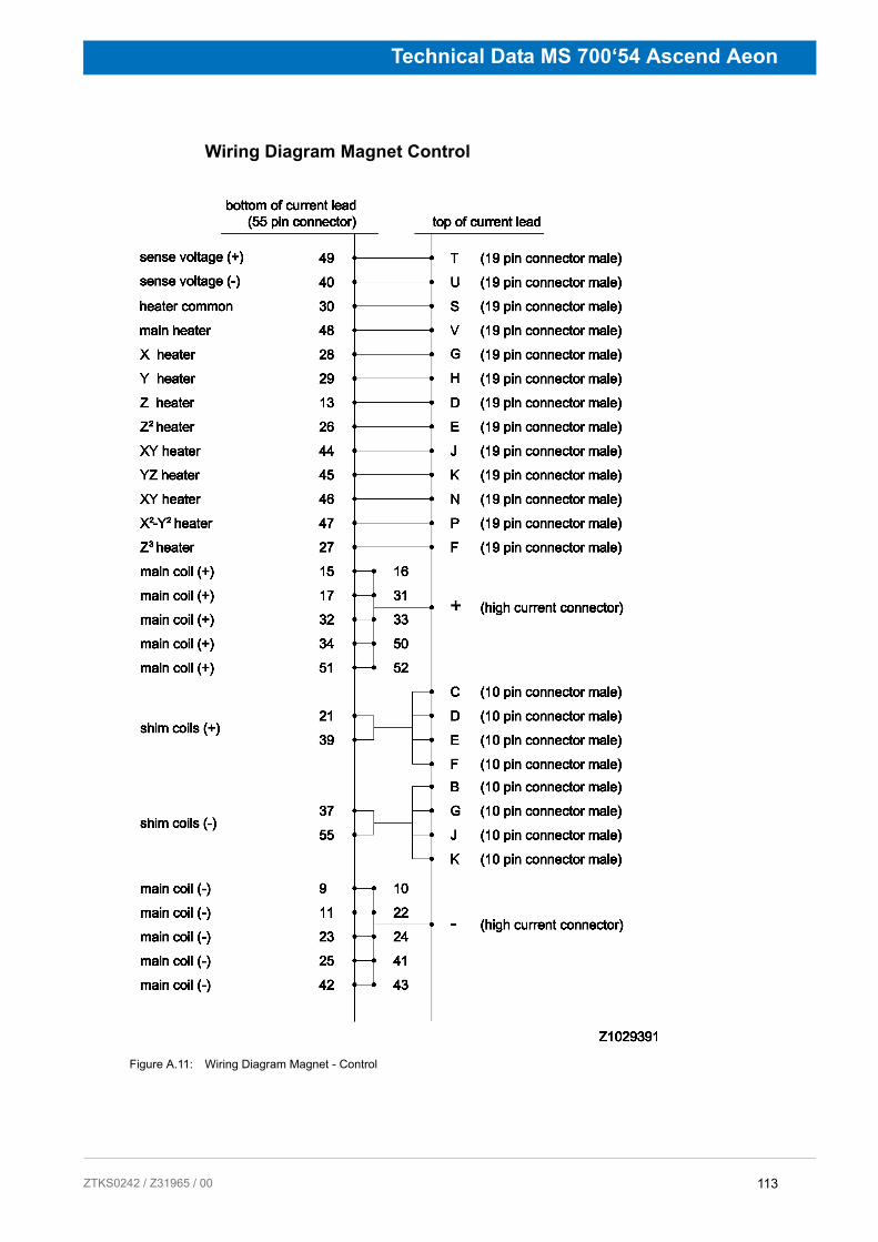
ZTKS0
Technical Data MS 700‘54 Ascend Aeon
Wiring Diagram Magnet Control
Figure A.11: Wiring Diagram Magnet - Control
113 242 / Z31965 / 00
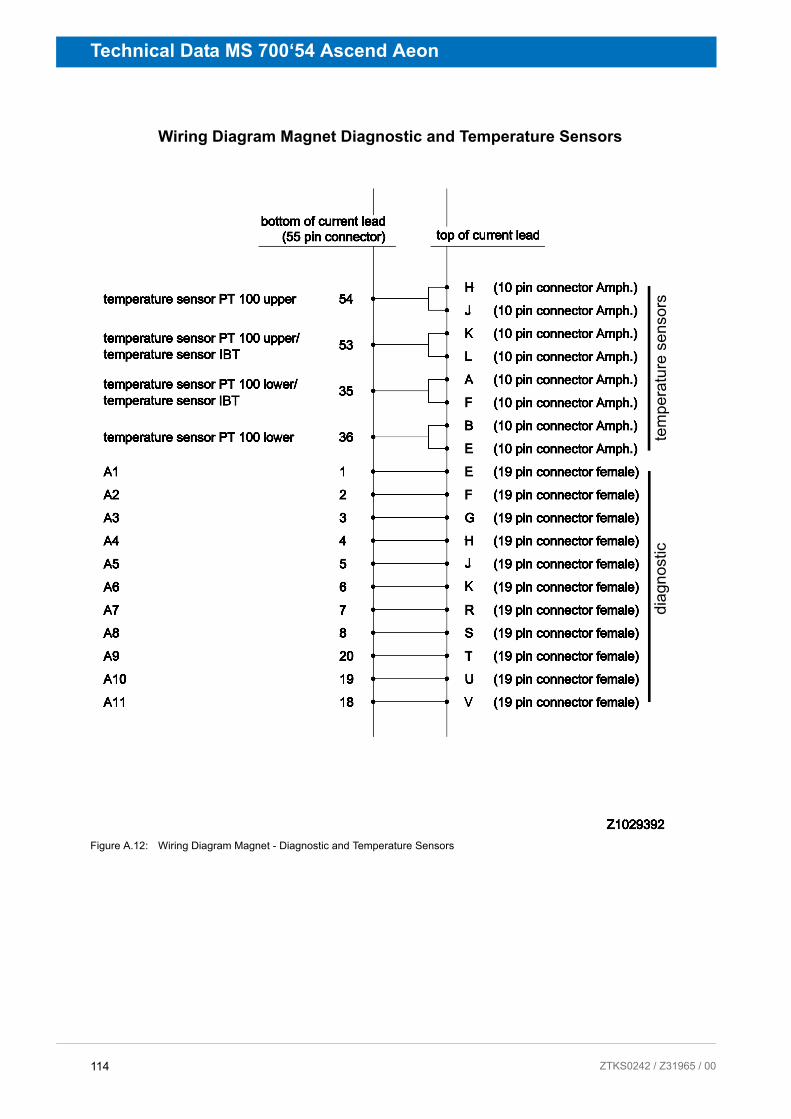
Technical Data MS 700‘54 Ascend Aeon
Wiring Diagram Magnet Diagnostic and Temperature Sensors
Figure A.12: Wiring Diagram Magnet - Diagnostic and Temperature Sensors
tem
pera
ture
sen
sors
diag
nost
ic
114 ZTKS0242 / Z31965 / 00

ZTKS0
Technical Data MS 700‘54 Ascend Aeon
Shorting Plug
The shorting plug is plugged after removal of the current lead. After inserting the shorting plug the current flows through the shorting plug and no longer through the current lead and the power supply.
1 Shorting Plug Tool for fitting and removing the shorting plug
2 Shorting Plug
3 Shorting Plug - view from pin side
Figure A.13: Shorting Plug 55 pins
115 242 / Z31965 / 00

Technical Data MS 700‘54 Ascend Aeon
This side is intentionally left blank.
116 ZTKS0242 / Z31965 / 00

ZTKS0
Technical Data MS 700‘54 Ascend Aeon
Resistance at Room Temperature _ _ _´_ _ _´_ _ _´_ _
Pin Connector Description Value Unit
From:To:
PIN VPIN S
19 PIN Con CONTROL19 PIN Con CONTROL
Main Heater Ω
From:To:
PIN DPIN S
19 PIN Con CONTROL19 PIN Con CONTROL
Z Heater Ω
From:To:
PIN GPIN S
19 PIN Con CONTROL19 PIN Con CONTROL
X Heater Ω
From:To:
PIN HPIN S
19 PIN Con CONTROL19 PIN Con CONTROL
Y Heater Ω
From:To:
PIN JPIN S
19 PIN Con CONTROL19 PIN Con CONTROL
XZ Heater Ω
From:To:
PIN KPIN S
19 PIN Con CONTROL19 PIN Con CONTROL
YZ Heater Ω
From:To:
PIN NPIN S
19 PIN Con CONTROL19 PIN Con CONTROL
XY Heater Ω
From:To:
PIN PPIN S
19 PIN Con CONTROL19 PIN Con CONTROL
X²–Y² Heater Ω
From:To:
PIN EPIN S
19 PIN Con CONTROL19 PIN Con CONTROL
Z² Heater Ω
From:To:
PIN FPIN S
19 PIN Con CONTROL19 PIN Con CONTROL
Z³ Heater Ω
From:To:
PIN C,D,E,F PIN B,G,J,K
10 PIN Con SHIM10 PIN Con SHIM
Shim Coils +/- Ω
From:To:
+PIN T
High current Con19 PIN Con CONTROL
High Current to Sense +
Ω
From:To:
+–
High current ConHigh current Con
Main Coil Ω
From:To:
–PIN U
High current Con19 PIN Con CONTROL
High Current to Sense –
Ω
From:To:
PIN TPIN U
19 PIN Con CONTROL19 PIN Con CONTROL
Sense +Sense –
Ω
From:To:
PIN CPIN S
10 PIN Con SHIM19 PIN Con CONTROL
Shim Coil toHeater (common)
Ω
From:To:
PIN CPIN T
10 PIN Con SHIM19 PIN Con CONTROL
Shim Coil toMain Coil
Ω
From:To:
PIN TPIN S
19 PIN Con CONTROL19 PIN Con CONTROL
Sense toHeater (common)
Ω
From:To:
All ConnectorsGround
Insulation Magnet to Cryostat
Ω
From:To:
PIN KPIN H
10 Pin cool down Con10 Pin cool down Con
Upper temperature sensor PT 100
Ω
From:To:
PIN APIN K
10 Pin cool down Con10 Pin cool down Con
IBT Carbon tem-perature sensor
Ω
From:To:
PIN APIN B
10 Pin cool down Con10 Pin cool down Con
Lower temperature sensor PT100
Ω
Table A.10: Resistance at Room Temperature
117 242 / Z31965 / 00

Technical Data MS 700‘54 Ascend Aeon
Heater Currents _ _ _´_ _ _´_ _ _´_ _
Energizing Assignment and Currents
Check the "minimum helium level for energizing" (refer to Figure A.3, page 104)
During energizing the Z2 shim heater must be permanently ON.
Heater Currents Value Unit
Main heater current A
Shim heater current A
Table A.11: Heater currents
Energizing Currents[A]
Sense voltage [mV]
Remarks Bruker Test Site
0 to 120 4000
120 to 170 2000
170 to 190 1000
190 to 205 500
205 to 200
Overshoot (0.25 % of final current)
to 50
10 Minutes break at overshoot current
to -50
Total energizing time [min]
Table A.12: Energizing assignment and currents
118 ZTKS0242 / Z31965 / 00

ZTKS0
Technical Data MS 700‘54 Ascend Aeon
Magnetic Center _ _ _´_ _ _´_ _ _´_ _
Refer to Figure A.1, page 100.
Cycling Assignment and Shim Currents
(recommended only for 500MHz and more)
Magnetic Center Value Unit
Magnet center from bottom flange M1 mm
Magnet center from top flange M2 mm
Table A.13: Magnetic Center
Cycling Assignment and Shim Currents Value Unit
Time between energizing and cycling (at least 12 h) h
Time between cycling and shimming (at least 12 h) h
Current rate A/h
Z-Shim current A
Z2-Shim current A
Z3-Shim current A
X–Shim current A
Y–Shim current A
XZ–Shim current A
YZ–Shim current A
XY–Shim current A
X2–Y2–Shim current A
Frequency change due to cycling kHz
Date and Signature
Table A.14: Cycling assignment (recommended only for 500Mhz and more)
119 242 / Z31965 / 00

Technical Data MS 700‘54 Ascend Aeon
Energizing Currents _ _ _´_ _ _´_ _ _´_ _
Energizing Currents ValueBruker Test Site
ValueCustomer Site #1
ValueCustomer Site #2
Unit
Magnet main current A
Z-Shim current A
Z2-Shim current A
Z3-Shim current A
X–Shim current A
Y–Shim current A
XZ–Shim current A
YZ–Shim current A
XY–Shim current A
X2–Y2–Shim current A
Magnetic center from bottom flange (measured)
mm
Magnetic center from top flange (measured)
mm
Date and Signature
Table A.15: Energizing currents
120 ZTKS0242 / Z31965 / 00

ZTKS0
Technical Data MS 700‘54 Ascend Aeon
Deenergizing Assignment and Currents _ _ _´_ _ _´_ _ _´_ _
Deenergizing Currents[A]
Sense voltage [mV]
Remarks Bruker Test Site
to 205 400
205 to 190 1000
190 to 0 2000 through external diodes
Total deenergizing time [min]
Table A.16: Deenergizing Assignment and Currents
121 242 / Z31965 / 00

Technical Data MS 700‘54 Ascend Aeon
This side is intentionally left blank.
122 ZTKS0242 / Z31965 / 00

ZTKS0
Technical Data MS 700‘54 Ascend Aeon
Magnet System Report
Helium level [%]
T RS[K]
Excess[mW]
Pressure[mbar]
Date, Time Signature
123 242 / Z31965 / 00

Technical Data MS 700‘54 Ascend Aeon
Magnet System Report
Helium level [%]
T RS[K]
Excess[mW]
Pressure[mbar]
Date, Time Signature
124 ZTKS0242 / Z31965 / 00

ZTKS0
Index
A.6 Index
AAttachment Point ......................................34
CCleaning Staff ...........................................16Cold Head ................................................12Complaint Process ...................................32Compressor ..............................................12Connection Line .......................................12Cryogenic Agents ...............................20, 21Cryogenic Refrigerator .......................13, 81
DDisturbances ............................................50Drop-off Plate ...........................................29
EElectricity ..................................................21Emergency ...............................................30Emergency Exit ........................................27
FFire Department .......................................30First Aid for Cold Burns ............................30Flex Lines .................................................12
IIdentification Plate ....................................99Intended Use ............................................18
LLiability .....................................................11Low Temperatures ...................................23
MMagnet Stand ...........................................12Magnetic Center .....................................119Magnetic Field ..........................................20
PPortable Oxygen Monitor ..........................26Protective Clothes ....................................26Protective Gloves .....................................26Protective Goggles ...................................26
QQuench ...............................................22, 78Quench Valve ...........................................29
125 242 / Z31965 / 00

Index
RRescue Equipment ...................................30Rotary Valve Column ...............................12
SSafety Devices .........................................28Safety Shoes ............................................26Shock Watch ............................................32Slippage ...................................................23Spontaneous Ignition ................................23
TTilt Watch .................................................32Tilting ........................................................24
WWarranty ...................................................11
126 ZTKS0242 / Z31965 / 00

ZTKS0
Revision History List
Index: Date: Alteration Type:
00 March 2014
First release.
127 242 / Z31965 / 00