6D 66D & 8D ACTIVE STUDIO MONITORS
12
6481 0412 6D 66D & 8D ACTIVE STUDIO MONITORS OWNERS MANUAL Tannoy adopts a policy of continuous improvement and product specification is subject to change. Tannoy United Kingdom T: +44 (0) 1236 420199 F: +44 (0) 1236 428230 E: [email protected] Tannoy North America T: (519) 745 1158 F: (519) 745 2364 E: [email protected] Tannoy Deutschland T: (04102) 888 393 F: (04102) 888 959 E: [email protected]
Transcript of 6D 66D & 8D ACTIVE STUDIO MONITORS

64
81 0
41
2
6D 66D & 8D ACTIVE STUDIO MONITORS
O W N E R S M A N U A L
Tannoy adopts a policy of continuous improvement and product specification is subject to change.
Tannoy United Kingdom T: +44 (0) 1236 420199 F: +44 (0) 1236 428230 E: [email protected]
Tannoy North America T: (519) 745 1158 F: (519) 745 2364 E: [email protected]
Tannoy Deutschland T: (04102) 888 393 F: (04102) 888 959 E: [email protected]

2 3
1.0: IMPORTANT SAFETY INSTRUCTIONS 1.1 Introduction
2.0: THE BASICS 2.1 Unpacking and visual checks
2.2 Preliminary recommendation
3.0: REVEAL D SERIES FEATURES 3.1 Analog Input
3.2 Digital SPDIF Input
3.3 Connecting your speakers
3.4 User Controls
4.0: EQUALISATION POSSIBILITIES
5.0: GUIDE TO SETTING THE EQUALISATION
6.0: PLACEMENT OF THE SPEAKERS 6.1 Orientation (R6D & R8D)
6.2 Positioning (R6D & R8D)
6.3 Positioning (R66D)
6.4 Speaker Mounting
6.5 Bass Ports
7.0: PERFORMANCE DATA Reveal 6D
Reveal 8D
Reveal 66D
8.0: TECHNICAL SPECIFICATIONS
9.0: DIMENSIONS
10.0: SERVICING 6.1 Cabinet Finish
6.2 Driver Removal
6.3 Amplifier Removal
6.4 Spare parts
11.0: WARRANTY
12.0: DECLARATION OF CONFORMITY
CO
NTEN
TS
1.0: IMPORTANT SAFETY INSTRUCTIONS
1. Read these instructions.
2. Keep these instructions.
3. Heed all warnings.
4. Follow all instructions.
5. Do not use this apparatus near water.
6. Clean only with dry cloth.
7. Do not block any ventilation openings. Install in accordance with manufacturer’s instructions.
8. Do not install near any heat sources such as radiators, heat registers, stoves, or other apparatus (including amplifiers) thatproduce heat and ensure adequate air circulation around the rear of the product.
9. Do not defeat the safety purpose of the polarised or grounding-type plug. A polarised plug has two blades with one widerthan the other. A grounding type plug has two blades and a third grounding prong. The wide blade or the third prong areprovided for your safety. If the provided plug does not fit into your outlet, consult an electrician for replacement of the obsolete outlet.
10. Protect the power cord from being walked on or pinched particularly at plugs, wall sockets, and the point where they exit from the apparatus.
11. Only use attachments/accessories specified by the manufacturer.
12. Unplug this apparatus during lightning storms or when unused for long periods of time.
13. Refer all servicing to qualified service personnel. Servicing is required when the apparatus has been damaged in any way,such as power-supply cord or plug is damaged, liquid has been spilled or objects have fallen into the apparatus, the apparatus has been exposed to rain or moisture, does not operate normally, or has been dropped.
14. WARNING: To reduce the risk of fire or electrical shock, this apparatus should not be exposed to rain or moisture and objectsfilled with liquids, such as vases, should not be placed on this apparatus.
15. To completely disconnect this equipment from the mains, disconnect the power supply cord plug from the wall socket.
16. The mains plug on the power supply cord shall remain readily accessible.
17. SAFETY WARNING: This product design uses amplifier output stages with substantial standing currents for optimal sound quality. Fit and use the protective heat shield when adjusting the feature controls above the heatsink, to prevent contact with uncomfortably hot surfaces when monitoring at continuously high sound pressure levels. Use the small tool provided to adjust the switches in accordance with the instructions in the user manual.
ELECTRICAL REQUIREMENTS
Check that the voltage rating displayed on the rear panel is correct for your area before connecting. If it is incorrect, pleaserefer to your local dealer or authorised service agent, as no user adjustment is provided.
Warning!• To reduce the risk of fire or electric shock, do not expose this apparatus to rain or moisture.• Be advised that different operating voltages require the use of different types of line cord and attachment plugs.• Check the voltage in your area and use the correct type. See table below:
Voltage Line plug according to standard110-125V UL817 and CSA C22.2 no 42.220-230V CEE 7 page VII, SR section 107-2-D1/IEC 83 page C4.240V BS 1363 of 1984. Specification for 13A fused plugs and switched and un-switched socket outlets.
ServiceThere are no user-serviceable parts inside. Qualified personnel must perform all service. Servicing is required when: -• The unit has been damaged in any way, such as when the power-supply cord or plug is damaged.• The unit has been exposed to rain or moisture, or liquid has been spilled into the unit.• Objects have fallen into the unit.• The unit does not work properly.• The unit has been dropped.
EUROPEAN MODELS
A mains cable is supplied with an IEC moulded socket at one end and a moulded mains plug at the other end. Where themoulded plug is fitted with a mains fuse, always replace with the same 5A rated fuse. If the fitted plug is unsuitable for yourtype of outlet sockets, it should be cut off and disposed of safely, in case it is inserted into a live socket elsewhere. The wires inthe mains cable are coloured in accordance with the following code:
GREEN AND YELLOW EARTH BLUE NEUTRAL BROWN LIVE
The lightning flash with an arrowhead symbol within anequilateral triangle, is intended to alert the user to thepresence of uninsulated “dangerous voltage” within theproduct’s enclosure that may be of sufficient magnitudeto constitute a risk of electric shock to persons.
The exclamation point within an equilateral triangle isintended to alert the user to the presence of importantoperating and maintenance (servicing) instructions in theliterature accompanying the product.

4 5
1.1: INTRODUCTION
The Tannoy Reveal Digital range of near field monitoring speakers builds upon the success and worldwide reputation of thefamous original Tannoy Reveal Active. Since the launch of the original Tannoy Reveal Active in 1998 there have been significantadvances in digital speaker measuring techniques, acoustic CAD design and simulation, and precision manufacturing processes. The Tannoy Reveal Digital range now provides greater bandwidth, significantly lower levels of distortion, smoother responses,more accurate phase control, and higher sensitivity levels; all within compact cabinet sizes. Also, much has been learnt aboutthe near field listening environment - the effects of boundary walls, acoustic reflections from mixing console surfaces and theacoustic properties of often sparsely prepared PC/Mac post production editing situations.
The Tannoy Reveal Digital range of monitoring speakers can be optimised for far field, mid field and near/close field free spacesituations right through to far field, mid field and near/close field situations in difficult acoustic spaces such as meter bridgepositions, adjacent to walls or reflecting surfaces and space restricted PC/Mac based sound editing environments.
Acoustic space environments are referred to as 4pi, 2pi and pi representing the solid angle in space (steradians) into which thespeaker is radiating. These environments are frequently referred to as free space, half space and quarter space listeningconditions . The type of acoustic space into which a speaker radiates, defined by nearby solid boundaries, affects the acousticair load presented to the speaker and so the relative radiating efficiency at various frequencies. In different pi spaces the linearityof the amplitude response changes, especially within the band 50Hz to 800Hz.
Varying distances encountered between the monitors and the listener are generally referred to as far field (greater than 3m or10 feet), mid field (2 to 3m or 6 to 10 feet), near field (1 to 2m or 3 to 6 feet) and close field (around 0.5m or 1.5 feet). Theproximity of the listener to the speaker changes the way the listener perceives the sound balance from the speaker. At largedistances from an acoustic source plane waves are perceived. At small distances from an acoustic source the waves appearspherical.
2.0: THE BASICS 2.1: UNPACKING AND VISUAL CHECKS
The Reveal 6D’s are packed in pairs and the Reveal 8D and 66D’s are packed singly. To remove the speakers from the cartonwithout damage open the end flaps fully and bend them right back (remember they are packed in pairs). Turn the packageupside-down on the floor and lift the carton vertically up to leave the speakers resting on their packing tray. Nothing on or inyour speakers should rattle about. Inspect each speaker for signs of transit damage. In the unlikely event of this having occurredinform the carrier and the supplier. Keep all the packaging if damage has occurred, as this will show evidence of excessivehandling forces. It is also a good idea to keep the packaging if possible for future transportation.
AS THE COLOURS OF THE WIRES IN THE MAINS CABLE MAY NOT CORRESPOND WITH THE COLOURED MARKINGSIDENTIFYING THE TERMINALS IN YOUR PLUG, PROCEED AS FOLLOWS:
The wire which is coloured GREEN AND YELLOW must be connected to the terminal in the plug which is marked either by theletter E, the earth safety symbol, or coloured GREEN or GREEN and YELLOW.
The wire which is coloured BLUE must be connected to the terminal in the plug which is marked by the letter N or coloured BLACK
The wire which is coloured BROWN must be connected to the terminal in the plug which is marked by the letter L or coloured RED.
Ensure that the terminals are tightened securely, and no loose strands of wire are present. Ensure cord grip is clamped overouter sheath of cable, rather than over the wires.
FUSE PROTECTION
An additional mains fuse is provided in the IEC power inlet on the back of the loudspeaker, which can only be removed withthe power cord unplugged. This must be replaced by a fuse of the same type and ratings (see Specifications or refer to rearpanel).
INSTALLATION
Do not install this equipment in an enclosed space. Do not limit free ventilation and movement of air around the back panel.Do not install this equipment in a cupboard with a closed door. Allow for a distance of 150mm (6 inches) of free air spacearound all sides, top, bottom and the back panel of this product. The user must be able to see the blue coloured front panelof this product when in use.
EMC
This equipment has been tested and found to comply with the limits for a Class B digital device, pursuant to part 15 of the FCCRules. These limits are designed to provide reasonable protection against harmful interference in a residential installation. Thisequipment generates uses and can radiate radio frequency energy and, if not installed and used in accordance with theinstructions, may cause harmful interference to radio communications. However, there is no guarantee that interference will notoccur in a particular installation. If this equipment does cause harmful interference to radio or television reception, which canbe determined by turning the equipment off and on, the user is encouraged to try to correct the interference by one or more ofthe following measures:
Reorient or relocate the receiving antenna. Increase the separation between the equipment and receiver. Connect the equipment into an outlet on a circuit different from that to which the receiver is connected. Reorient or coil cables. If necessary, consult the dealer or an experienced radio/television technician for additional suggestions.
Any cables the user adds to the device must be shielded to be in compliance with the FCC standards. Any unauthorised modificationto this device could result in the revocation of the end user’s authority to operate this device.
This device complies with Part 15 of FCC rules. Operation is subject to the following two conditions: (1) This device may notcause harmful interference, and (2) This device must accept any interference received, including interference that may causeundesired operation.
CanadaIndustry Canada Class B emission compliance statement. This Class B digital apparatus complies with Canadian ICES-003.Avis de conformite a la reglementation d'Industrie Canada. Cet appareil numerique de classe B est conforme a la norme NMB-003 du Canada.
2.2: PRELIMINARY RECOMMENDATION
Initially we would like to give a word of warning on high sound levels, which these speakers are capable of generating oversustained periods of time. Levels over 95 dB for 8 hours per day can eventually cause permanent hearing loss. Because Tannoymonitors have very low levels of time, amplitude and frequency distortion it is not always obvious that the sound level is highwhile working with them.
For continuous exposure we recommend the occasional use of a sound level meter capable of integrating the sound level overa period of exposure according to noise control standards. This should be used just to check that noise levels are always withinsafety limits.
3.0: REVEAL D SERIES FEATURES
A set of DIP switches on the rear panel of each speaker can be set to choose the optimum speaker response for these real lifeand often difficult situations, so that the frequency response from the speaker is always substantially flat. We are not equalisingthe room modes due to standing waves or resonant structures, we are equalising the speaker to take account of the varying airload presented by the room and surrounding large structures such as the mixing desk.
The switches are arranged in groups according to their function and each switch can be set to the 'on' (down) or 'off' (up) positionin various combinations to achieve a flatter, more balanced response within a wide variety of acoustic spaces and with far, mid,near and close field monitoring positions.
Figure 1 shows the range of equalisation available in the 50Hz to 800Hz region and also shows the degree of trim availablein the bass, upper midrange and high frequency areas,

6 7
An A/V 80Hz high pass filter switch provides instant conversion to 5.1 and higher order systems where a separate subwooferbelow 80Hz is required. Filter characteristics are according to the international standards for this setup. This response is alsoshown diagramatically in Figure 1.
Listening to well recorded male or female spoken word or vocals at the normal listening position is a good way to check andoptimise the available settings. Difficult environments and variable listening distances produce varying degrees of boost fromthe flat position in the 50Hz to 800Hz area. Graphical representations of the responses available by setting the switches areshown below. The linear or flat response positions for the DIP switches are always clearly shown in the diagrams below andalso on the rear panel of the speaker.
The Tannoy ActivAssist™ software package is available to help with the DIP switch settings. Using a standard laptop with themicrophone and cables supplied in the pack, the performance of the speaker in a particular environment can be assessed anda recommended set of switches set up.
Fig. 1. Full range of equalisation and trim available.
Fig. 2. Range of adjustment available and settings for the first 4 DIP switches. All other DIPs set to 'Flat'
Diagramatic View of EQ Dip Switches: LF EQ + Av Filter
20 way DIP Switch Bank (4+4+2+4+6)
10Hz 100Hz 1Khz 10kHz
-10dB
+10dB
0dB re 2.8v @ 1 metre
500Hz 5kHz200Hz 2kHz 20kHz20Hz 50Hz
LF EQ Low Mids Hz Up Highs
1 1 1 0 1 1 1 0 0 0 0 0 0 0 0 0 0 0 0 0
1 1 1 1 1 1 1 0 0 0 0 0 0 0 0 0 0 0 0 0
1 1 0 0 1 1 1 0 0 0 0 0 0 0 0 0 0 0 0 0
0 0 0 0 1 1 1 0 0 0 0 0 0 0 0 0 0 0 0 0
1 0 0 0 1 1 1 0 0 0 0 0 0 0 0 0 0 0 0 0
80Hz AV Filter (AV on/off)
Mids
3.1: ANALOG INPUT
XLR: 2= +ve (hot), 3= -ve (cold), 1= screen, shield or signal ground.3 way Jack: tip=+ve (hot), ring= -ve (cold), sleeve= screen, shield or signal ground.For unbalanced XLR connection short pin 1 to pin 3 and use 2= +ve (hot), 3= -ve (ground).For unbalanced 3 way Jack short ring to sleeve and use tip= +ve (hot), sleeve= -ve (ground).
3.2: DIGITAL SPDIF INPUT
The input impedance is the SPDIF specification at 75 ohms and the 24 bit DAC supports 44.1, 48 and 96kHz sampling rates.Please use a high quality* SPDIF coaxial phono (RCA) cable to connect the source equipment (eg CD player, DAT/ADAT or PCsound card) to one of the speakers. Connect a second (phono to phono) high quality cable from this speaker to the secondspeaker of the stereo pair. Select whether each speaker converts left channel or right channel audio as appropriate using theswitch adjacent to the SPDIF input connector. For true mono requirements set the switch to mono. If volume can be controlledfrom the source equipment, set the source equipment volume level to minimum and the speaker volume control to maximum(fully clockwise). If volume cannot be controlled by the source equipment (eg a simple CD or DAT etc) set the volume controlon the speaker to minimum (fully anticlockwise) to prevent excessive sound levels. The volume control adjusts the analoguelevel after the DA converters to preserve the full digital dynamic range.
* In order to comply fully with EMC regulations, the SPDIF input and SPDIF thru should be connected using metal-shelledconnectors and good quality shielded cable suitable for digital audio.
3.3: CONNECTING YOUR SPEAKERS
Having chosen an appropriate location for your monitors and arranged them accordingly, connect the power cord to the mainssocket and turn the power on. The LED on the front panel will now glow red. Push the Tannoy logo on the front panel to operatethe switch to bring the amplifier out of standby mode and into operational mode. Set the volume control on the rear panel tozero (fully anticlockwise). Connect the audio signal source (console output) to the input connector (combined XLR/jack socket)or SPDIF at the back of the monitor.
3.4: USER CONTROLS
A/V (80Hz): a switch to the bottom left of the bank of DIP switches sets the system high pass filter to either flat or –6dB at 80Hz. The 80Hz setting is used when the speakers are in combination with a subwoofer for low frequency effects such as Dolby Digital,AC3, DTS etc playback situations. For all other situations set this switch to flat. This response can be seen in Figure 1 above.
Left/Right/Mono: a switch at the bottom left of the bank of DIP switches sets the SPDIF DAC to sense the left, right or combinedstereo information (mono) from the digital stream. Set the left hand speaker to ‘Left’ and the right hand speaker to ‘Right’ for2 channel stereo, or to ‘mono’ for single speaker monitoring.
Analogue/Digital: a switch adjacent to the XLR/Jack combi socket selects whether the speaker is receiving a signal from thebalanced/unbalanced analogue input combi socket, or, from the SPDIF phono (RCA) digital input. Both may be connectedsimultaneously but only one can be selected at any one time.
4.0: EQUALISATION POSSIBILITIES
Note: In the diagrams which follow, the corner frequency shown as 50Hz will vary according to the specification relating tothe particular model which has been chosen. Please refer to the detailed specification section at the end of this manual for moredetails. Smaller models will have a slightly higher corner frequency and larger models will have a lower corner frequency. Thediagrams have been prepared to make the visualisation of the EQ possibilities easier to understand. The transitions of thespeaker amplitude response bewteen frequency bands will be gradual and not as sharp as the diagrams show. Note the +10dBand -10dB calibrations on the charts. EQ settings should never be at opposite extremes eg -8dB low mid contour with -2dBmids and +3dB highs.
There are 4 basic frequency bands that can be adjusted. The range of adjustment is purposely restricted so that although effectivein the majority of environments, it is difficult to set the speaker to have a totally unacceptable response. A 'flat' setting meansflat within specification as measured in an anechoic chamber, on axis, under free field conditions in the far field (3 metres away).The frequency bands are:
Bass Corner Frequency: The 'Q' value of the bass unit and cabinet volume alignment can be altered giving +3dB, flat, -1.5, -3, and -4.5 dB relative to the -3dB point shown in the specification. This provides a degree of boost and cut in the 45Hzto 65Hz area. Figure 2 shows the range of adjustment available together with the DIP switch settings for the first 4 DIP switches.All other DIP switches are shown in the anechoic flat positions.
+3dB+1.5dB Large Medium Normal +1.5dB +2dB
+0.75dB +1dB0dB Flat Flat Flat Flat
-2dB -0.75dB -1dB-1dB -4dB
-1.5dB -2dB-6dB -3dB-2dB-8dB
-3dB
( AV 80Hz HiPass on slide switch)

8 9
Low Mid Contour Frequency: A shelving filter can be set to the flat anechoic response or set to shelve at frequencies of 800Hz,
400Hz, or 200Hz in combination with the low mid contour amplitude (below) to correct half space (pi/2), quarter space (pi/4)
and very difficult close field boundary conditions (pi/8 space).
Low Mid Contour: a shelving filter can be set to a flat anechoic response or to -2dB, -4dB, -6dB or -8dB in combination with
the low mid contour frequency (above) to correct mid, near and close field listening positions compared with free space, far
field conditions.
Figures 3, 4 and 5 below show the range of amplitude settings at 800Hz, 400Hz and 200Hz and the DIP switch settings. DIPs
5 to 8 (inclusive) control the amplitude responses and switches 9 and 10 control the frequency at which the shelving starts. All
other DIPs are shown in the 'Flat' position.
Baffle Step Effect: Both low mid frequency and low mid contour are used together to correct for the baffle step effect. the baffle
step effect is a well known property of speakers and is caused by a change in air load on the moving diaphragm at a frequency
dependant on the effective size of the baffle or cabinet frontal area compared with the wavelength of the sound being reproduced.
Most speakers are designed to have a flat amplitude and phase response over the audio band in anechoic or 'free field'
conditions where there are no boundary walls close to the bass drive unit. When the speaker is placed against a wall, in a
corner, on a mixing console or on a table adjacent to a PC editor the wall boundaries effectively increase the baffle size. This
produces a boost in the frequency band around 100 to 800 Hz depending on the effective size and proximity of the boundary
surfaces, the size of the bass driver and the distance of the listener from the source.
More at: Olson, H. F. "Direct Radiator Loudspeaker Enclosures" Journal of the Audio Engineering Society Vol. 17, No. 1, 1969
October, pp.22-29
There are many more references to these effects by searching the web for 'Baffle Step Effect'.
Fig. 3. DIP switches 5 to 8 control amplitude, 9 & 10 control frequency - set here to 800Hz. All other DIPs set to 'flat'.
10Hz 100Hz 1Khz 10kHz
-10dB
+10dB
0dB re 2.8v @ 1 metre
500Hz 5kHz200Hz 2kHz 20kHz20Hz 50Hz
LF EQ Low Mids Hz Up Mid Highs
1 1 1 0 0 0 0 1 0 0 0 0 0 0 0 0 0 0 0 0
1 1 1 0 1 1 1 0 0 0 0 0 0 0 0 0 0 0 0 0
1 1 1 0 0 1 1 0 0 0 0 0 0 0 0 0 0 0 0 0
1 1 1 0 0 0 0 0 0 0 0 0 0 0 0 0 0 0 0 0
1 1 1 0 0 0 1 0 0 0 0 0 0 0 0 0 0 0 0 0
Diagramatic View of EQ Dip Switches: Baffle Step Filters, Low Mids, 800Hz
20 way DIP Switch Bank (4+4+2+4+6)
Fig. 5. DIP switches 5 to 8 control amplitude, 9 & 10 control frequency - set here to 200Hz. All other DIPs set to 'flat'.
10Hz 100Hz 1Khz 10kHz
-10dB
+10dB
0dB re 2.8v @ 1 metre
500Hz 5kHz200Hz 2kHz 20kHz20Hz 50Hz
LF EQ Low Mids Hz Up Mid Highs
1 1 1 0 0 0 0 1 1 1 0 0 0 0 0 0 0 0 0 0
1 1 1 0 1 1 1 0 0 0 0 0 0 0 0 0 0 0 0 0
1 1 1 0 0 1 1 0 1 1 0 0 0 0 0 0 0 0 0 0
1 1 1 0 0 0 0 0 1 1 0 0 0 0 0 0 0 0 0 0
1 1 1 0 0 0 1 0 1 1 0 0 0 0 0 0 0 0 0 0
Diagramatic View of EQ Dip Switches: Baffle Step Filters, Low Mids, 200Hz
20 way DIP Switch Bank (4+4+2+4+6)
Fig. 4. DIP switches 5 to 8 control amplitude, 9 & 10 control frequency - set here to 400Hz. All other DIPs set to 'flat'.
10Hz 100Hz 1Khz 10kHz
-10dB
+10dB
0dB re 2.8v @ 1 metre
500Hz 5kHz200Hz 2kHz 20kHz20Hz 50Hz
LF EQ Low Mids Hz Up Mid Highs
1 1 1 0 0 0 0 1 1 0 0 0 0 0 0 0 0 0 0 0
1 1 1 0 1 1 1 0 0 0 0 0 0 0 0 0 0 0 0 0
1 1 1 0 0 1 1 0 1 0 0 0 0 0 0 0 0 0 0 0
1 1 1 0 0 0 0 0 1 0 0 0 0 0 0 0 0 0 0 0
1 1 1 0 0 0 1 0 1 0 0 0 0 0 0 0 0 0 0 0
Diagramatic View of EQ Dip Switches: Baffle Step Filters, Low Mids, 400Hz
20 way DIP Switch Bank (4+4+2+4+6)

10 11
Hi-Mid Shelf Boost/Cut: a shelving filter between 1kHz and 3KHz can be set to +2, +1dB, flat, -1dB, -2dB, to take account
of room characteristics and personal preference. Editing news broadcast material is often easier with an increased output in
this band. Figure 6 shows the range of adjustment in this area controlled by DIP switches 11 to 14.
High Frequency Shelf Boost/Cut: a shelving filter between 5kHz and 50kHz can be set to +3dB, +2dB; +1dB, flat anechoic,
-1dB, -2dB, -3dB to take account of RT60 decay times for the environment within this band and to allow a degree of personal
preference. Figure 7 shows the range available diagramatically.
10Hz 100Hz 1Khz 10kHz500Hz 5kHz200Hz 2kHz 20kHz20Hz 50Hz
1 1 1 0 1 1 1 0 0 0 0 0 1 1
1 1 1 0 1 1 1 0 0 0 1 1 0 0 0 0 0 0 0 0
1 1 1 0 1 1 1 0 0 0 0 1 0 0 0 0 0 0 0 0
1 1 1 0 1 1 1 0 0 0 0 0 1 0
1 1 1 0 1 1 1 0 0 0 0 0 0 0
LF EQ Low Mids Hz Up Mid Highs
Diagramatic View of EQ Dip Switches: Upper Midband Filter Settings
20 way DIP Switch Bank (4+4+2+4+6)
-10dB
+10dB
0dB re 2.8v @ 1 metre
Fig. 6. Range of EQ available for DIP switches 11 to 14. All other DIPs set to 'Flat'.
10Hz 100Hz 1Khz 10kHz500Hz 5kHz200Hz 2kHz 20kHz20Hz 50Hz
1 1 1 0 1 1 1 0 0 0 0 0 0 0 0 0 0 1 1 0
1 1 1 0 1 1 1 0 0 0 0 0 0 0 1 1 1 0 0 0
1 1 1 0 1 1 1 0 0 0 0 0 0 0 0 1 1 0 0 0
1 1 1 0 1 1 1 0 0 0 0 0 0 0 0 0 0 1 0 0
1 1 1 0 1 1 1 0 0 0 0 0 0 0 0 0 1 0 0 0
1 1 1 0 1 1 1 0 0 0 0 0 0 0 0 0 0 0 0 0
1 1 1 0 1 1 1 0 0 0 0 0 0 0 0 0 0 1 1 1
LF EQ Low Mids Hz Up Mid Highs
Diagramatic View of EQ Dip Switches: High Frequency Filter Settings
20 way DIP Switch Bank (4+4+2+4+6)
Fig. 7. The range of upper HF EQ controlled by DIP switches 15 to 20. All other DIPs set to 'Flat'
-10dB
+10dB
0dB re 2.8v @ 1 metre
5.0: A GUIDE TO SETTING THE EQUALISATION
Assess the monitoring conditions and consider these 4 main factors:
1. The environment: free space (4pi), half space (2pi), quarter space (pi) and in the extreme, a "Difficult Space" (pi/2)
2. The distance from the speakers: far field (2 to 3m), mid field (1 to 2m), near field (0.5 to1m) or close field (less than 0.5m)
3. The room: absorbent or reflective surfaces, estimate the RT 60 decay time above 1kHz
4. The nature of the source material: prolonged sessions working on editing bright or forward material can produce fatigue.
10Hz 100Hz 1Khz 10kHz500Hz 5kHz200Hz 2kHz 20kHz20Hz 50Hz
-10dB
+10dB
0dB re 2.8v @ 1 metre
1 1 1 0 1 1 1 0 0 0 0 0 0 0 0 0 0 0 0 0
Free Space (4Pi): An example of free space conditions would be with the speakers mounted on tall (0.5m to 1.2m) speaker
stands well away from the wall at one end of a room and with the listener 2 to 3 meters away. Under these conditions set all
the DIP switches to the 'flat anechoic' position. This then provides a high quality high fidelity installation operating in good
acoustically treated environments.
Half Space (2Pi): An example of half space would be with speakers against a wall mounted on stands as above, or on the
meter bridge with the console in the centre of a room. Follow the DIP settings in the diagram below for half space (Pi/2) and
adjust for the listening distance accordingly. Adjust the LF-Q settings to balance the system.
10Hz 100Hz 1Khz 10kHz500Hz 5kHz200Hz 2kHz 20kHz20Hz 50Hz
1 1 1 0 0 1 1 0 0 0 0 0 0 0 0 0 0 0 0 0
-10dB
+10dB
0dB re 2.8v @ 1 metre
0 0 0 0 0 0
0 0 0 0 0 0
0 0 0 0 0 0

12 13
1 1 1 0 0 0 1 0 1 0 0 0 0 0 0 0 0 0 0 0 0 0
-10dB
+10dB
0dB re 2.8v @ 1 metre
Quarter Space (Pi): An example of quarter space would be with speakers mounted on stands in a corner, or on the meter
bridge against a wall or mounted on small stands or shelves against a wall. Also typical PC/Mac editing in a confined space
on a desk near a wall. This is usually also a close field situation. Follow the DIP settings below for Quarter Space and adjust
for the listening distance accordingly. Adjust the LF-Q settings to balance the system.
10Hz 100Hz 1Khz 10kHz500Hz 5kHz200Hz 2kHz 20kHz20Hz 50Hz
10Hz 100Hz 1Khz 10kHz500Hz 5kHz200Hz 2kHz 20kHz20Hz 50Hz
-10dB
+10dB
0dB re 2.8v @ 1 metre
1 1 1 0 0 0 0 0 1 1 0 0 0 0 0 0 0 0 0 0 0
"Difficult Space" (pi/2): An example of a difficult space would be with speakers against a wall, mounted on the same surface
as the PC/Mac machine tilted upwards towards the listener with one or other (or both!) speakers in a corner. This is also a close
field situation and demands extreme EQ to make the speakers measure reasonably flat. Typical examples might be a mobile
or temporary sound booth set up during an outside broadcast or live field event. Follow the DIP settings in the diagram below
for "Difficult Space" for the speakers in corners and adjust for the listening distance accordingly. Adjust the LF-Q settings to
balance the system.
Notes
14 15
MID AND HIGH EQ SETTINGS
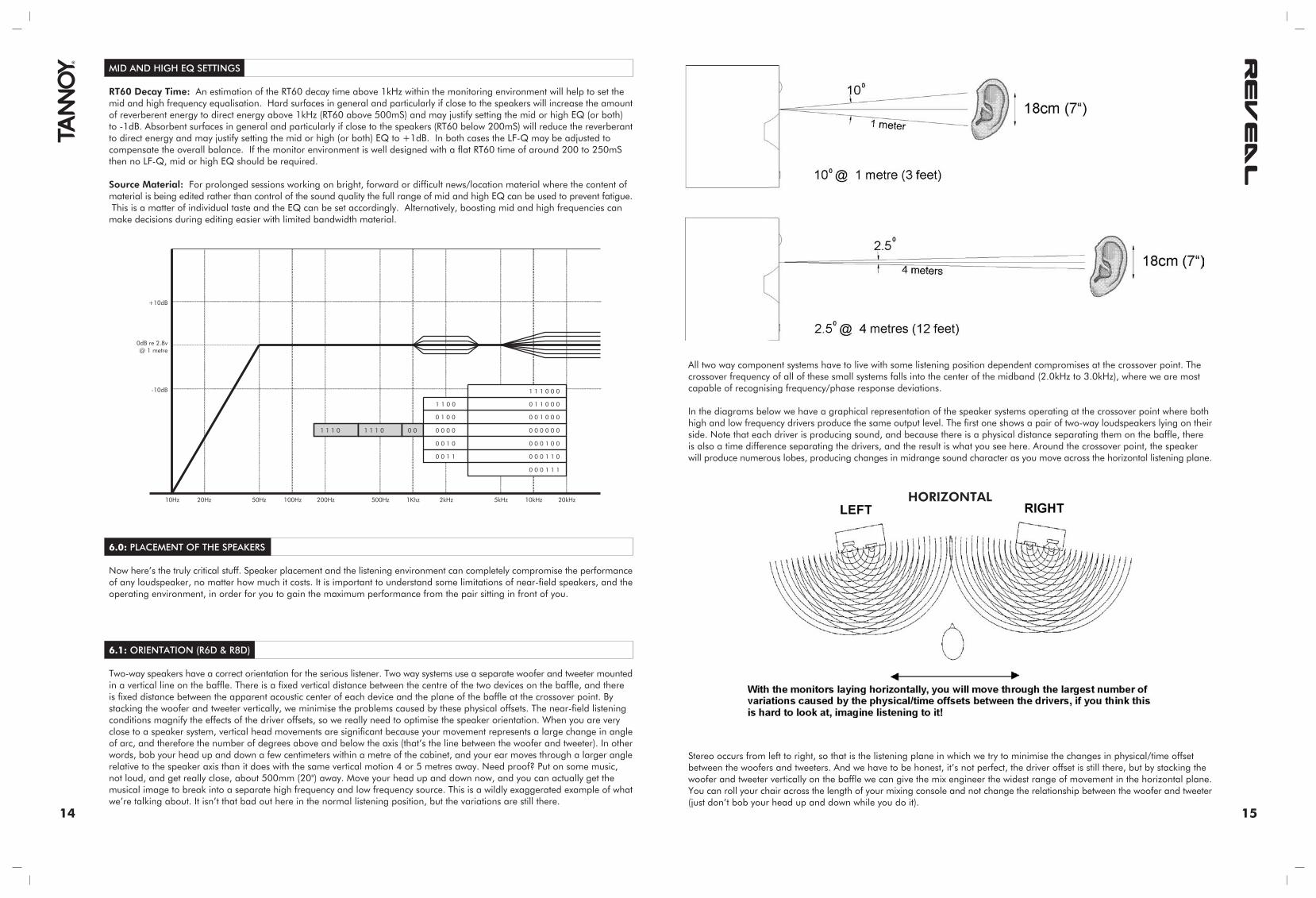
RT60 Decay Time: An estimation of the RT60 decay time above 1kHz within the monitoring environment will help to set themid and high frequency equalisation. Hard surfaces in general and particularly if close to the speakers will increase the amountof reverberent energy to direct energy above 1kHz (RT60 above 500mS) and may justify setting the mid or high EQ (or both)to -1dB. Absorbent surfaces in general and particularly if close to the speakers (RT60 below 200mS) will reduce the reverberantto direct energy and may justify setting the mid or high (or both) EQ to +1dB. In both cases the LF-Q may be adjusted tocompensate the overall balance. If the monitor environment is well designed with a flat RT60 time of around 200 to 250mSthen no LF-Q, mid or high EQ should be required.
Source Material: For prolonged sessions working on bright, forward or difficult news/location material where the content ofmaterial is being edited rather than control of the sound quality the full range of mid and high EQ can be used to prevent fatigue. This is a matter of individual taste and the EQ can be set accordingly. Alternatively, boosting mid and high frequencies canmake decisions during editing easier with limited bandwidth material.
10Hz 100Hz 1Khz 10kHz500Hz 5kHz200Hz 2kHz 20kHz20Hz 50Hz
1 1 1 0 1 1 1 0 0 0 0 0 0 0 0 0 0 0 0 0
0 1 0 0 0 0 1 0 0 0
1 1 0 0 0 1 1 0 0 0
0 0 1 0 0 0 0 1 0 0
0 0 1 1 0 0 0 1 1 0
1 1 1 0 0 0
0 0 0 1 1 1
-10dB
+10dB
0dB re 2.8v @ 1 metre
6.0: PLACEMENT OF THE SPEAKERS
Now here’s the truly critical stuff. Speaker placement and the listening environment can completely compromise the performanceof any loudspeaker, no matter how much it costs. It is important to understand some limitations of near-field speakers, and theoperating environment, in order for you to gain the maximum performance from the pair sitting in front of you.
6.1: ORIENTATION (R6D & R8D)
Two-way speakers have a correct orientation for the serious listener. Two way systems use a separate woofer and tweeter mountedin a vertical line on the baffle. There is a fixed vertical distance between the centre of the two devices on the baffle, and thereis fixed distance between the apparent acoustic center of each device and the plane of the baffle at the crossover point. Bystacking the woofer and tweeter vertically, we minimise the problems caused by these physical offsets. The near-field listeningconditions magnify the effects of the driver offsets, so we really need to optimise the speaker orientation. When you are veryclose to a speaker system, vertical head movements are significant because your movement represents a large change in angleof arc, and therefore the number of degrees above and below the axis (that’s the line between the woofer and tweeter). In otherwords, bob your head up and down a few centimeters within a metre of the cabinet, and your ear moves through a larger anglerelative to the speaker axis than it does with the same vertical motion 4 or 5 metres away. Need proof? Put on some music,not loud, and get really close, about 500mm (20") away. Move your head up and down now, and you can actually get themusical image to break into a separate high frequency and low frequency source. This is a wildly exaggerated example of whatwe’re talking about. It isn’t that bad out here in the normal listening position, but the variations are still there.
All two way component systems have to live with some listening position dependent compromises at the crossover point. Thecrossover frequency of all of these small systems falls into the center of the midband (2.0kHz to 3.0kHz), where we are mostcapable of recognising frequency/phase response deviations.
In the diagrams below we have a graphical representation of the speaker systems operating at the crossover point where bothhigh and low frequency drivers produce the same output level. The first one shows a pair of two-way loudspeakers lying on theirside. Note that each driver is producing sound, and because there is a physical distance separating them on the baffle, thereis also a time difference separating the drivers, and the result is what you see here. Around the crossover point, the speakerwill produce numerous lobes, producing changes in midrange sound character as you move across the horizontal listening plane.
Stereo occurs from left to right, so that is the listening plane in which we try to minimise the changes in physical/time offsetbetween the woofers and tweeters. And we have to be honest, it’s not perfect, the driver offset is still there, but by stacking thewoofer and tweeter vertically on the baffle we can give the mix engineer the widest range of movement in the horizontal plane.You can roll your chair across the length of your mixing console and not change the relationship between the woofer and tweeter(just don’t bob your head up and down while you do it).
HORIZONTAL
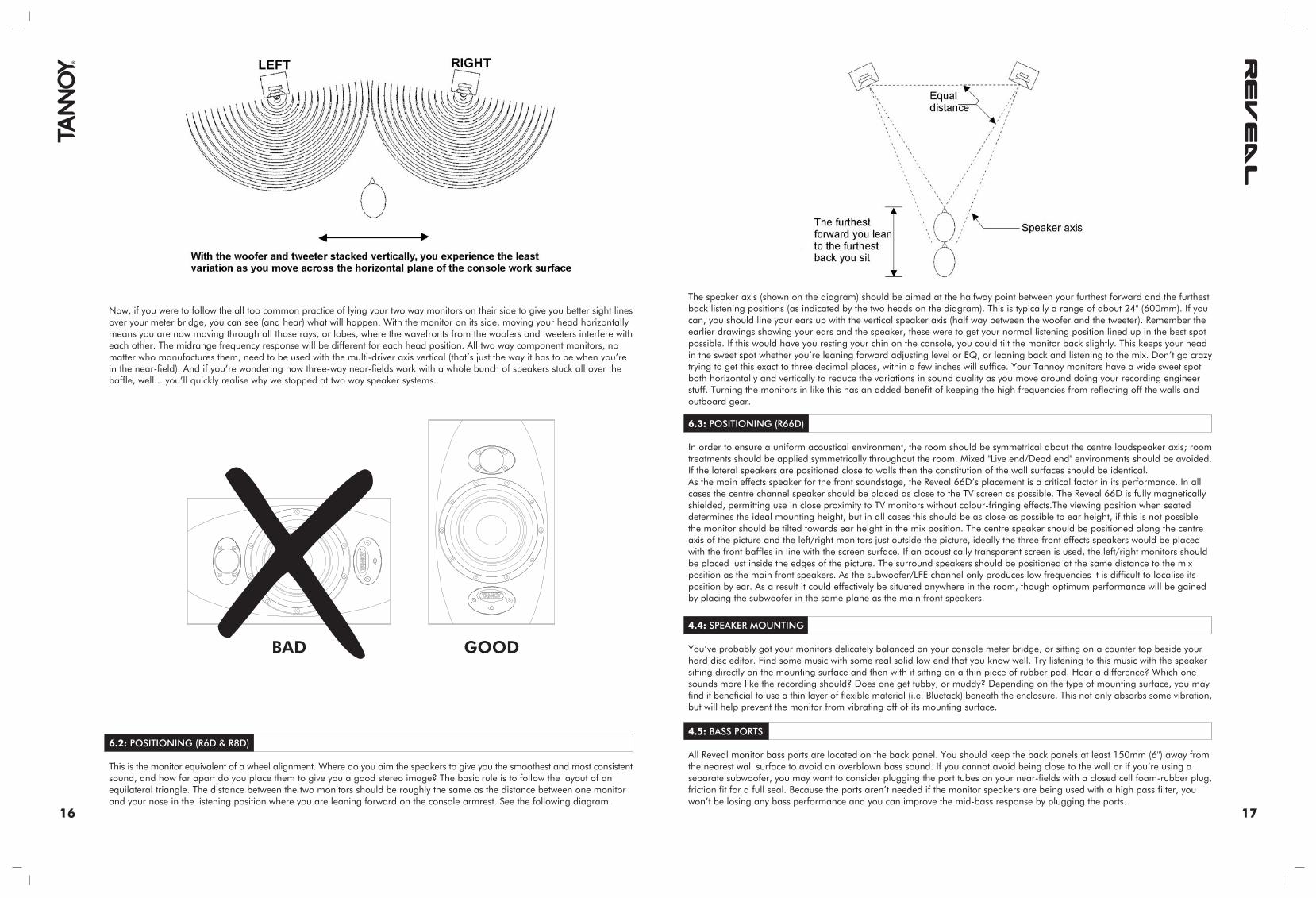
Now, if you were to follow the all too common practice of lying your two way monitors on their side to give you better sight linesover your meter bridge, you can see (and hear) what will happen. With the monitor on its side, moving your head horizontallymeans you are now moving through all those rays, or lobes, where the wavefronts from the woofers and tweeters interfere witheach other. The midrange frequency response will be different for each head position. All two way component monitors, nomatter who manufactures them, need to be used with the multi-driver axis vertical (that’s just the way it has to be when you’rein the near-field). And if you’re wondering how three-way near-fields work with a whole bunch of speakers stuck all over thebaffle, well... you’ll quickly realise why we stopped at two way speaker systems.
16 17
6.2: POSITIONING (R6D & R8D)
This is the monitor equivalent of a wheel alignment. Where do you aim the speakers to give you the smoothest and most consistentsound, and how far apart do you place them to give you a good stereo image? The basic rule is to follow the layout of anequilateral triangle. The distance between the two monitors should be roughly the same as the distance between one monitorand your nose in the listening position where you are leaning forward on the console armrest. See the following diagram.
The speaker axis (shown on the diagram) should be aimed at the halfway point between your furthest forward and the furthestback listening positions (as indicated by the two heads on the diagram). This is typically a range of about 24" (600mm). If youcan, you should line your ears up with the vertical speaker axis (half way between the woofer and the tweeter). Remember theearlier drawings showing your ears and the speaker, these were to get your normal listening position lined up in the best spotpossible. If this would have you resting your chin on the console, you could tilt the monitor back slightly. This keeps your headin the sweet spot whether you’re leaning forward adjusting level or EQ, or leaning back and listening to the mix. Don’t go crazytrying to get this exact to three decimal places, within a few inches will suffice. Your Tannoy monitors have a wide sweet spotboth horizontally and vertically to reduce the variations in sound quality as you move around doing your recording engineerstuff. Turning the monitors in like this has an added benefit of keeping the high frequencies from reflecting off the walls andoutboard gear.
6.3: POSITIONING (R66D)
In order to ensure a uniform acoustical environment, the room should be symmetrical about the centre loudspeaker axis; roomtreatments should be applied symmetrically throughout the room. Mixed "Live end/Dead end" environments should be avoided.If the lateral speakers are positioned close to walls then the constitution of the wall surfaces should be identical.As the main effects speaker for the front soundstage, the Reveal 66D’s placement is a critical factor in its performance. In allcases the centre channel speaker should be placed as close to the TV screen as possible. The Reveal 66D is fully magneticallyshielded, permitting use in close proximity to TV monitors without colour-fringing effects.The viewing position when seateddetermines the ideal mounting height, but in all cases this should be as close as possible to ear height, if this is not possiblethe monitor should be tilted towards ear height in the mix position. The centre speaker should be positioned along the centreaxis of the picture and the left/right monitors just outside the picture, ideally the three front effects speakers would be placedwith the front baffles in line with the screen surface. If an acoustically transparent screen is used, the left/right monitors shouldbe placed just inside the edges of the picture. The surround speakers should be positioned at the same distance to the mixposition as the main front speakers. As the subwoofer/LFE channel only produces low frequencies it is difficult to localise itsposition by ear. As a result it could effectively be situated anywhere in the room, though optimum performance will be gainedby placing the subwoofer in the same plane as the main front speakers.
4.4: SPEAKER MOUNTING
You’ve probably got your monitors delicately balanced on your console meter bridge, or sitting on a counter top beside yourhard disc editor. Find some music with some real solid low end that you know well. Try listening to this music with the speakersitting directly on the mounting surface and then with it sitting on a thin piece of rubber pad. Hear a difference? Which onesounds more like the recording should? Does one get tubby, or muddy? Depending on the type of mounting surface, you mayfind it beneficial to use a thin layer of flexible material (i.e. Bluetack) beneath the enclosure. This not only absorbs some vibration,but will help prevent the monitor from vibrating off of its mounting surface.
4.5: BASS PORTS
All Reveal monitor bass ports are located on the back panel. You should keep the back panels at least 150mm (6") away fromthe nearest wall surface to avoid an overblown bass sound. If you cannot avoid being close to the wall or if you’re using aseparate subwoofer, you may want to consider plugging the port tubes on your near-fields with a closed cell foam-rubber plug,friction fit for a full seal. Because the ports aren’t needed if the monitor speakers are being used with a high pass filter, youwon’t be losing any bass performance and you can improve the mid-bass response by plugging the ports.
BAD GOOD
18 19
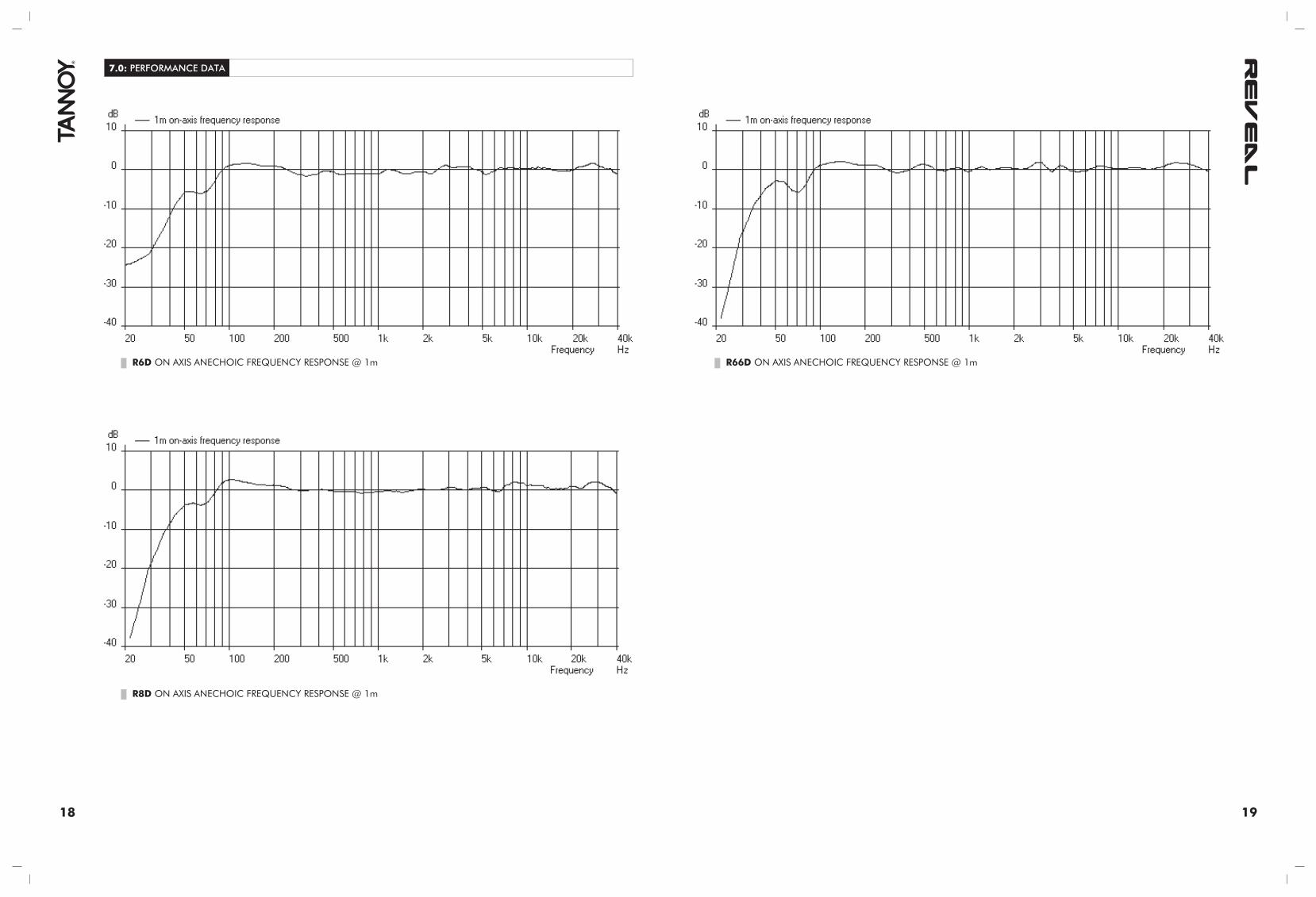
7.0: PERFORMANCE DATA
R6D ON AXIS ANECHOIC FREQUENCY RESPONSE @ 1m
R8D ON AXIS ANECHOIC FREQUENCY RESPONSE @ 1m
R66D ON AXIS ANECHOIC FREQUENCY RESPONSE @ 1m

20 21
8.0: TECHNICAL SPECIFICATIONS
Frequency response (1)
Maximum SPL (2)
Distortion
Dispersion (@-6dB)
Drive unit LF/MID
WideBand™ HF
Shielded
SYSTEM
60Hz – 51 kHz
115dB
<0.5%
90 degrees
165mm (6") multi fibre paperpulp cone
25mm (1") titanium domeneodymium magnet system
Yes
Low frequency design
Cabinet construction
Cabinet finish
Cabinet dimensions (HxWxD)
Total Cabinet weight
CABINET
Optimised bass-reflex loaded
MDF cabinet and front baffle,tongue and groove front and back
Grey cabinet with blue paintedbaffle
340mm x 210mm x 381mm133/8” x 81/4” x 15”
7.8kg (17.15lbs)
R6D R8D R66D
46Hz-51kHz
118dB
<0.4%
90 degrees
2 x 165mm (6") multi fibre paperpulp cone
25mm (1") titanium domeneodymium magnet system
Yes
47Hz-51kHz
117dB
<0.4%
90 degrees
200mm (8") multi fibre paper pulpcone
25mm (1") titanium domeneodymium magnet system
Yes
(1) +/- 3 dB, measured at 1m in an anechoic chamber. (2) Peak SPL at mix position for 1 pair driven.
Tannoy operates a policy of continuous research and development. The introduction of new materials or manufacturing methods will always equal or exceed the published specifications which Tannoy reserve the right to alter withoutprior notice. Please verify the latest specifications when dealing with critical applications.
NOTES
Input
Sensitivity
Crossover frequency
Amplifier output power
User Controls
Power supply
ELECTRONIC SECTION
600Ω balanced on combinedXLR/jack
0.775 Vrms for Full Output
2.6kHz
LF 75 W rms HF 35 W rms
Front panel mountedon/standby/mute LED indicatorRear Trim +6/-12dB80Hz High-Pass switch (for AVuse)16-way DIP switch selection forresponse optimisation
Fixed mains voltageIEC inlet with detachable powercordRegion Specific (to order)110/220/230v
600Ω balanced on combinedXLR/jack
0.775 Vrms for Full Output
2.5kHz
LF 120 W rms HF 60 W rms
Front panel mountedon/standby/mute LED indicatorRear Trim +6/-12dB80Hz High-Pass switch (for AVuse)16-way DIP switch selection forresponse optimisation
Fixed mains voltageIEC inlet with detachable powercordRegion Specific (to order)110/220/230v
600Ω balanced on combinedXLR/jack
0.775 Vrms for Full Output
2.6kHz
LF 100 W rms HF 50 W rms
Front panel mountedon/standby/mute LED indicatorRear Trim +6/-12dB80Hz High-Pass switch (for AVuse)16-way DIP switch selection forresponse optimisation
Fixed mains voltageIEC inlet with detachable powercordRegion Specific (to order)110/220/230v
9.0: DIMENSIONS
R6D
R8D
R66D
262.0mm330.5mm
363.5mm
425.0mm
210.0mm339.5mm
381.0mm
340.0mm
527.0mm 375.5mm
408.5mm
230.0mm
Optimised bass-reflex loaded
MDF cabinet and front baffle,tongue and groove front and back
Grey cabinet with blue paintedbaffle
425mm x 262mm x 363.5mm163/4” x 105/16” x 145/16”
16kg (35.2lbs)
Optimised bass-reflex loaded
MDF cabinet and front baffle,tongue and groove front and back
Grey cabinet with blue paintedbaffle
230mm x 527mm x 408.5mm91/16” x 203/4” x 131/16”
17.3kg (38lbs)
203/4”
91/16”
161/16”
143/4”
13”
145/16”
105/16”
163/4”
81/4”
133/8”
133/8”
15”

22 23
11.0: WARRANTY
NO MAINTENANCE OF THE REVEAL 6D, 8D & 66D MONITORS IS NECESSARY.
All components are guaranteed for a period of one year from the date of manufacture, subject to the absence of, or evidenceof, misuse, overload or accidental damage.
For further information please contact your dealer or the distributor in your country.
If you cannot locate your distributor please contact:
Customer Services, Tannoy Ltd., Coatbridge, Strathclyde, ML5 4TF, Scotland
Telephone: 01236 420199 (UK) +44 1236 420199 (International)Fax: 01236 428230 (UK) +44 1236 428230 (International)Internet: http://www.tannoy.com
DO NOT SHIP ANY PRODUCT TO TANNOY WITHOUT PREVIOUS AUTHORISATION
This warranty in no way affects your statutory rights.
12.0: DECLARATION OF CONFORMITY
The following apparatus is/are manufactured in China by Tannoy Ltd of Rosehall Industrial Estate, Coatbridge, Scotland, ML54TF. The following equipment is marked with the CE label and conform(s) to the protection requirements of the EuropeanElectromagnetic Compatibility Standards and Directives. The apparatus is designed and constructed such that electromagneticdisturbances generated do not exceed levels allowing radio and telecommunications equipment and other apparatus to operateas intended, and, the apparatus has an adequate level of intrinsic immunity to electromagnetic disturbance to enable operationas specified and intended.
Details of the Apparatus: Reveal 6D Studio MonitorReveal 8D Studio MonitorReveal 66D Studio Monitor
The equipment listed above is covered by this certificate and marked with the CE-label conforms to the following standards:
EN 60065 Safety requirements for mains operated electronic and related
(IEC 60065) apparatus for household and similar general use
EN 55103-1 Product family standard for audio, video, audio-visual and entertainment lighting control apparatusfor professional use. Part 1: Emission.
EN 55103-2 Product family standard for audio, video, audio-visual and entertainment lighting control apparatusfor professional use. Part 2: Immunity.
With reference to regulations in following directives:73/23/EEC, 89/336/EEC
Signed:
Position: Technical Director
Date: 1 March 2005
For Tannoy Ltd
10.0: SERVICING 10.1: CABINET FINISH
To remove marks and scuffs use a soft brush. If necessary, a little warm water and detergent can be used but under nocircumstances use a solvent or abrasive cleaner.
10.2: DRIVER REMOVAL
Lay the cabinet on its back. Remove the ten hexagonal screws and set aside. Ease the driver from the front of the cabinet takingcare not to mark the front surface. Remove the driver, note the polarity of the internal connections and disconnect the internalwiring. Take care not to damage the moving parts of the LF driver. To refit the driver, connect the cables from the crossover tothe LF terminals. Fit the driver into the mounting hole, making sure that the internal connecting cables are not trapped or ableto touch the LF cone. Fasten the screws finger tight and then progressively tighten them down with the appropriate Allen key.Repeat the same procedure for the HF driver.
10.3: AMPLIFIER
A fuse is located just under the mains input (fig 1). Replacement is simple and a spare fuse is provided inside the fuse housingitself. Always use the correctly rated fuse, as indicated on the silk screen-printing. Only qualified and authorised personnel shouldundertake any other servicing regarding the amplifier section.
In case of any malfunction of the unit, the first thing to check should be the input connection, more especially if the source hasunbalanced outputs (see "Connecting your speakers" section) as improper connection can result in significant level reductionand affect the response.
10.4: LIST OF SPARE PARTS
Driver Kit
High Frequency Unit
Amplifier Complete
Amplifier Complete
Filter Board Assembly
Power Board Assembly
Digital I/O Board Assembly
Features Board Assembly
Transformer
Passive Crossover
DESCRIPTION REVEAL 6D (PART NO)
Type 1603 -7900 0747
Type 0294 – 7900 0891B
7300 0932 (230V)
7300 1026 (110V)
7600 1550
7600 1556
7600 1558
7600 1409
3212 0132
REVEAL 8D (PART NO)
Type 2076 -7900 0748
Type 0294 – 7900 0891B
7300 0933 (230V)
7300 1027 (110V)
7600 1551
7600 1557
7600 1558
7600 1409
3212 0133
REVEAL 66D (PART NO)
Type 1603 -7900 0747
Type 0294 – 7900 0891B
7300 0934 (230V)
7300 1028 (110V)
7600 1552
7600 1557
7600 1558
7600 1409
3212 0132
Type 1509 – 7300 1044