8D - D38999 Stainless Steel Series - Air Electro, Inc. Electrical
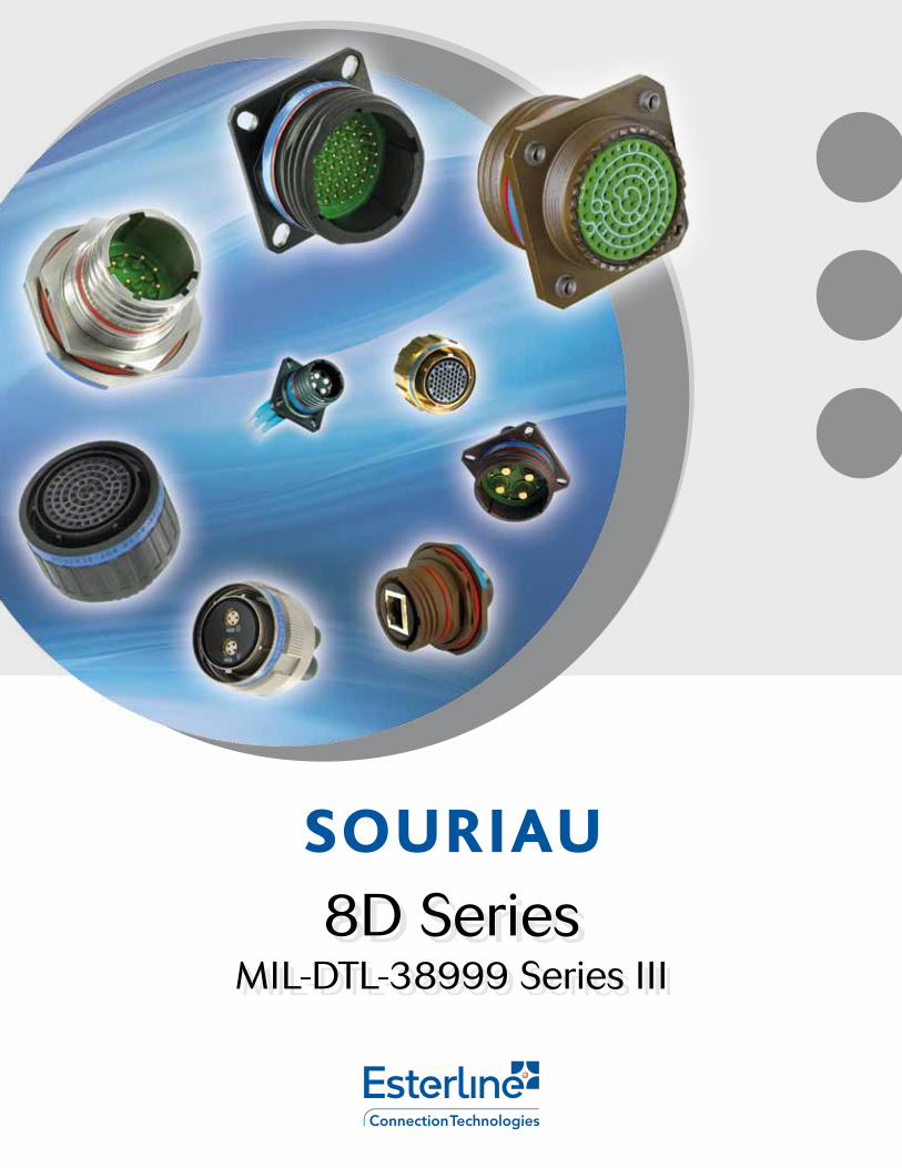
8D SeriesMIL-DTL-38999 Series III

8D SeriesMIL-DTL-38999 Series III
3© 2013 - SOURIAU
• Solder cup ...................................................................................
• Crimp contacts: 1500 mating ..............................................
• Wire wrap contacts ..................................................................
• Quadrax #8 contacts ...............................................................
• Thermocouple contacts .........................................................
• Dummy contacts .......................................................................
• Filler plugs ....................................................................................
• Wiring instruction ......................................................................
• Crimping tools ............................................................................
• Insertion and extraction tools .............................................
• Gaskets .........................................................................................
• Plastic protective caps ............................................................
• Orientations ................................................................................
• Panel cut-out ...............................................................................
• Coordinates for straight PC tail terminations ................
• Reinforced sealing Series ......................................................
• Hermetic Series .........................................................................
• Integrated clinch nuts .............................................................
• Double flange .............................................................................
• PCB contacts without shoulder ...........................................
• High density ................................................................................
• Quadrax contacts ......................................................................
• Power contacts ..........................................................................
• High power contacts ................................................................
• BMA coaxial contacts .............................................................
• Optical ELIO® Contacts ...........................................................
• RJ45/USB Series ......................................................................
• micro38999 ................................................................................
• 8D hermetic ELIO® feedthrough .........................................
• Rack & panel ...............................................................................
• 230V connector .......................................................................
• 8D8 / 8D9 Series ......................................................................
• 8DB bulkhead feedthrough ..................................................
• 8PS Series ....................................................................................
• 8D hermetic aluminum power & signal ...........................
• 8D36 lanyard release .............................................................
• 8TFD filter connector ..............................................................
Contents
• A universal product platform ...............................................
• 8D Series - Presentation .......................................................
• Product overview ......................................................................
• A superior concept ..................................................................
• A performing MIL standard connector design ............
• Technical features & benefits .............................................
• Contact layouts .........................................................................
• Contact layouts (matrix) .........................................................
• Aluminum Series
Part numbers ................................................................
Dimensions ...................................................................
Backshells ......................................................................
Dummy receptacle .....................................................
Caps ................................................................................
Connectors weight ......................................................
• Composite Series
Part numbers ................................................................
Dimensions ...................................................................
Backshells ......................................................................
Connectors weight ......................................................
• Stainless Steel Series
Part numbers ................................................................
Dimensions ...................................................................
Connectors weight ......................................................
• Titanium Series
Part numbers ................................................................
Dimensions ...................................................................
Connectors weight ......................................................
• Bronze Series
Part numbers ................................................................
Dimensions ...................................................................
Backshells ......................................................................
Caps ................................................................................
• Crimp contacts ..........................................................................
• Straight PC tail contacts ........................................................
• Coax contacts #12 ..............................................................
0607080910111318
222427333335
36384041
424447
484952
53545761
646667
676767676868686970717272 737374
84869396100102104110115120124130
138138139139140140141141142142
Overview
Common Section
Standard Series
Derived Series
Range Extension

8D Series
Overview8D Series
A universal product platform .......................................................................................................
8D Series - Presentation ...............................................................................................................
Product overview .............................................................................................................................
A superior concept .........................................................................................................................
A performing MIL standard connector design ......................................................................
Technical features & benefits .......................................................................................................
Contact layouts ................................................................................................................................
Contact layouts (matrix) .................................................................................................................
06
07
08
09
10
11
13
18
8D SeriesMIL-DTL-38999 Series III
6 © 2013 - SOURIAU
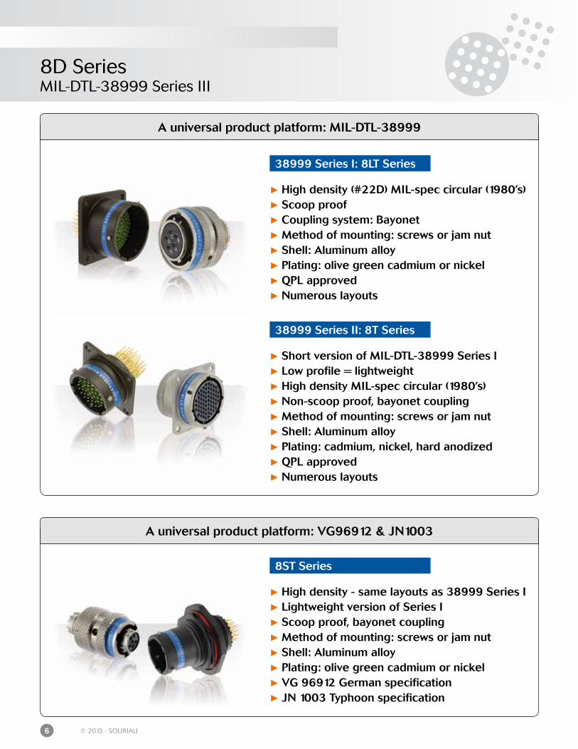
A universal product platform: VG96912 & JN1003
8ST Series
High density - same layouts as 38999 Series I Lightweight version of Series I Scoop proof, bayonet coupling Method of mounting: screws or jam nut Shell: Aluminum alloy Plating: olive green cadmium or nickel VG 96912 German specification JN 1003 Typhoon specification
A universal product platform: MIL-DTL-38999
38999 Series II: 8T Series
Short version of MIL-DTL-38999 Series I Low profile = lightweight High density MIL-spec circular (1980’s) Non-scoop proof, bayonet coupling Method of mounting: screws or jam nut Shell: Aluminum alloy Plating: cadmium, nickel, hard anodized QPL approved Numerous layouts
38999 Series I: 8LT Series
High density (#22D) MIL-spec circular (1980’s) Scoop proof Coupling system: Bayonet Method of mounting: screws or jam nut Shell: Aluminum alloy Plating: olive green cadmium or nickel QPL approved Numerous layouts
8D SeriesMIL-DTL-38999 Series III
7© 2013 - SOURIAU
8D Series - Presentation
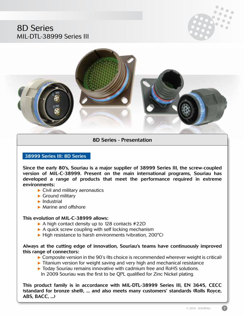
Since the early 80’s, Souriau is a major supplier of 38999 Series III, the screw-coupled version of MIL-C-38999. Present on the main international programs, Souriau has developed a range of products that meet the performance required in extreme environments: Civil and military aeronautics Ground military Industrial Marine and offshore
This evolution of MIL-C-38999 allows: A high contact density up to 128 contacts #22D A quick screw coupling with self locking mechanism High resistance to harsh environments (vibration, 200°C)
Always at the cutting edge of innovation, Souriau’s teams have continuously improved this range of connectors: Composite version in the 90’s (Its choice is recommended wherever weight is critical) Titanium version for weight saving and very high and mechanical resistance Today Souriau remains innovative with cadmium free and RoHS solutions. In 2009 Souriau was the first to be QPL qualified for Zinc Nickel plating.
This product family is in accordance with MIL-DTL-38999 Series III, EN 3645, CECC (standard for bronze shell), ... and also meets many customers’ standards (Rolls Royce, ABS, BACC, ...)
38999 Series III: 8D Series
8D SeriesMIL-DTL-38999 Series III
8 © 2013 - SOURIAU
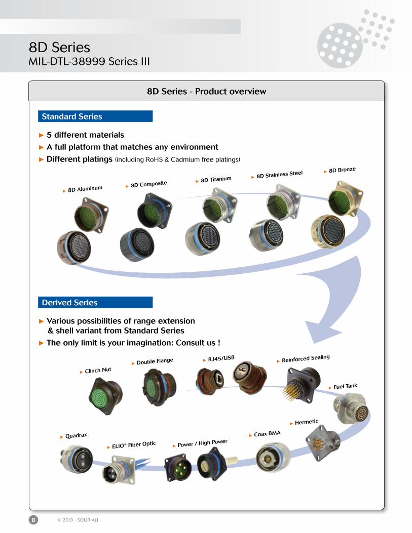
8D Series - Product overview
Standard Series
Derived Series
5 different materials
A full platform that matches any environment
Different platings (including RoHS & Cadmium free platings)
Various possibilities of range extension & shell variant from Standard Series
The only limit is your imagination: Consult us !
Quadrax
Power / High Power
Reinforced Sealing
Hermetic
Clinch Nut Double Flange
Fuel Tank
ELIO® Fiber Optic Coax BMA
8D Aluminum 8D Composite 8D Stainless Steel 8D Bronze
8D Titanium
RJ45/USB
8D SeriesMIL-DTL-38999 Series III
9© 2013 - SOURIAU
8D Series - A superior concept
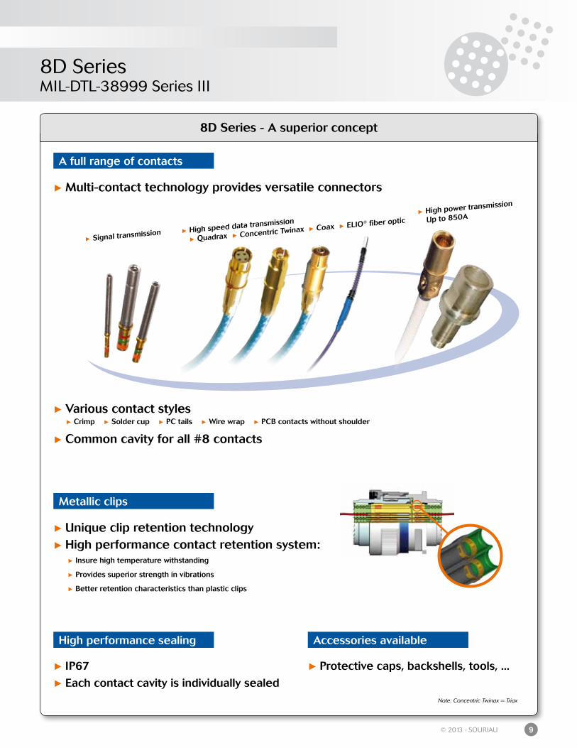
A full range of contacts
Multi-contact technology provides versatile connectors
Various contact styles Crimp Solder cup PC tails Wire wrap PCB contacts without shoulder
Common cavity for all #8 contacts
Signal transmission
High power transmission
Up to 850A
High speed data transmission
Quadrax Concentric Twinax Coax ELIO® fiber optic
Metallic clips
Unique clip retention technology High performance contact retention system: Insure high temperature withstanding
Provides superior strength in vibrations
Better retention characteristics than plastic clips
High performance sealing
IP67
Each contact cavity is individually sealed
Accessories available
Protective caps, backshells, tools, ...
Note: Concentric Twinax = Triax
8D SeriesMIL-DTL-38999 Series III
10 © 2013 - SOURIAU
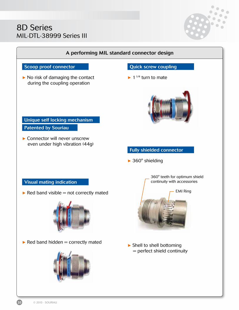
A performing MIL standard connector design
EMI Ring
360° teeth for optimum shield continuity with accessories
Quick screw coupling
Fully shielded connector
Scoop proof connector
No risk of damaging the contact during the coupling operation
Visual mating indication
Red band visible = not correctly mated
Red band hidden = correctly mated
1 1/4 turn to mate
360° shielding
Shell to shell bottoming = perfect shield continuity
Patented by Souriau
Connector will never unscrew even under high vibration (44g)
Unique self locking mechanism
8D SeriesMIL-DTL-38999 Series III
11© 2013 - SOURIAU
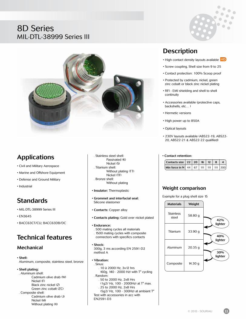
Description• High contact density layouts available
• Screw coupling, Shell size from 9 to 25
• Contact protection: 100% Scoop proof
• Protected by cadmium, nickel, green zinc cobalt or black zinc nickel plating
• RFI - EMI shielding and shell to shell continuity
• Accessories available (protective caps, backshells, etc… )
• Hermetic versions
• High power up to 850A
• Optical layouts
• 230V layouts available (ABS22-19, ABS22- 20, ABS22-21 & ABS22-22 qualified)
Applications• Civil and Military Aerospace
• Marine and Offshore Equipment
• Defense and Ground Military
• Industrial
Standards• MIL-DTL-38999 Series III
• EN3645
• BACC63CT/CU; BACC63DB/DC
Technical features
Mechanical
• Shell: Aluminum, composite, stainless steel, bronze
• Shell plating: . Aluminum shell: Cadmium olive drab (W) Nickel (F) Black zinc nickel (Z) Green zinc cobalt (ZC) . Composite shell: Cadmium olive drab (J) Nickel (M) Without plating (X)
. Stainless steel shell: Passivated (K) Nickel (S) . Titanium shell: Without plating (TT) Nickel (TF) . Bronze shell: Without plating
• Insulator: Thermoplastic
• Grommet and interfacial seal: Silicone elastomer
• Contacts: Copper alloy
• Contacts plating: Gold over nickel plated
• Endurance: . 500 mating cycles all materials . 1500 mating cycles with composite connectors with specifics contacts
• Shock: 300g, 3 ms according EN 2591-D2 method A
• Vibration: . Sinus: . 10 à 2000 Hz, 3x12 hrs (60g, 140 - 2000 Hz) with T° cycling . Random: . 50 to 2000 Hz, 2x8 Hrs (1g2/ Hz, 100 - 2000Hz) at T° max. . 25 to 2000 Hz, 2x8 Hrs (5g2/ Hz, 100 - 300Hz) at ambiant T° Test with accessories in acc with EN2591-D3
• Contact retention:
Weight comparison
Example for a plug shell size 15
Materials Weight
Stainless steel
58.80 g
Titanium 33.90 g
Aluminum 20.35 g
Composite 14.30 g
42%lighter
40%lighter
30%lighter
HD
Contacts size 22 20 16 12 8 4
Min force in N 44 67 111 111 111 200
8D SeriesMIL-DTL-38999 Series III
12 © 2013 - SOURIAU
Electrical
• Test voltage rating (Vrms)
• Contact resistance
• Insulation resistance: ≥ 5 000 MΩ (under 500 Vdc)
• Contact rating:
• Shell continuity . Aluminum shell: Cadmium olive drab (W): 2.5 mΩ Nickel (F): 1 mΩ Black zinc nickel (Z): 2.5 mΩ Green zinc cobalt (ZC): 2.5 mΩ . Composite shell: Cadmium olive drab (J): 3 mΩ Nickel (M): 3 mΩ . Stainless steel shell: Passivated (K): 10 mΩ Nickel (S): 1 mΩ . Titanium shell: Without plating (TT): 10 mΩ Nickel (TF): 1 mΩ . Bronze shell: Without plating: 5 mΩ
• Shielding: . Aluminum shell: F: 65 db at 10 GHz Z, F & W: 85 db at 1 GHz Z & W: 50 db at 10 GHz ZC: Consult us . Composite shell: J & M: 85 db at 1 GHz . Stainless steel shell: K: 45 db at 10 GHz S: 65 db at 10 GHz . Titanium shell: TT: 45 db at 10 GHz TF: 65 db at 10 GHz . Bronze shell: 85 db at 10 GHz
Climatics
• Temperature range: . Aluminum shell: W: -65°C +175°C F: -65°C +200°C Z: -65°C +200°C ZC: -65°C +175°C . Composite shell: J: -65°C +175°C M: -65°C +200°C Without plating (X): -65°C +175° . Stainless steel shell: K: -65°C +200°C S: -65°C +200°C . Titanium shell: TT: -65°C +200°C TF: -65°C +200°C . Bronze shell: Without plating: -65°C +175°C
• Sealing: Mated connectors meet altitude immersion requirements of MIL-DTL-38999.
• Salt spray: . Aluminum shell: W: 500 Hrs F: 48 Hrs Z: 500 Hrs ZC: 250 Hrs . Composite shell: J: 2000 Hrs M: 2000 Hrs Without plating (X): 2000 Hrs . Stainless steel shell: K: 500 Hrs S: 500 Hrs . Titanium shell: TT: 500 Hrs TF: 48 Hrs . Bronze shell: Without plating: 500 Hrs
Resistance to fluids
• According to MIL-DTL-38999 standard . Gasoline: JP5 (OTAN F44) . Mineral hydraulic fluid: MIL-H-5606 (OTAN H515) . Synthetic hydraulic fluid: Skydrol 500 B4
• LD4 (SAE AS 1241) . Mineral lubricating: MIL-L-7870A (OTAN 0142) . Synthetic lubricating: MIL-L-23699 (OTAN 0156), MIL-L-7808 . Cleaning fluid: MIL-DTL-25769 diluted . De-icing fluid: MIL-A-8243 . Extinguishing fluid: Chlorobrométhane . Cooling fluid: Coolanol
Service sea level at 21000 mR 400 N/AM 1 300 800N 1 000 600I 1 800 1 000II 2 300 1 000
Contacts size 26 22 20 16 12 8 4
Resistance mΩ 16 14.6 7.3 3.8 3.5 3 2
Contacts size 26 22 20 16 12 8 4
Rating (A) 3 5 7.5 13 23 45 80
8D SeriesMIL-DTL-38999 Series III
13© 2013 - SOURIAU
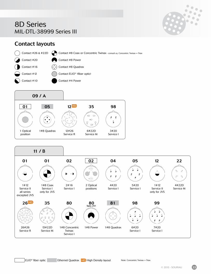
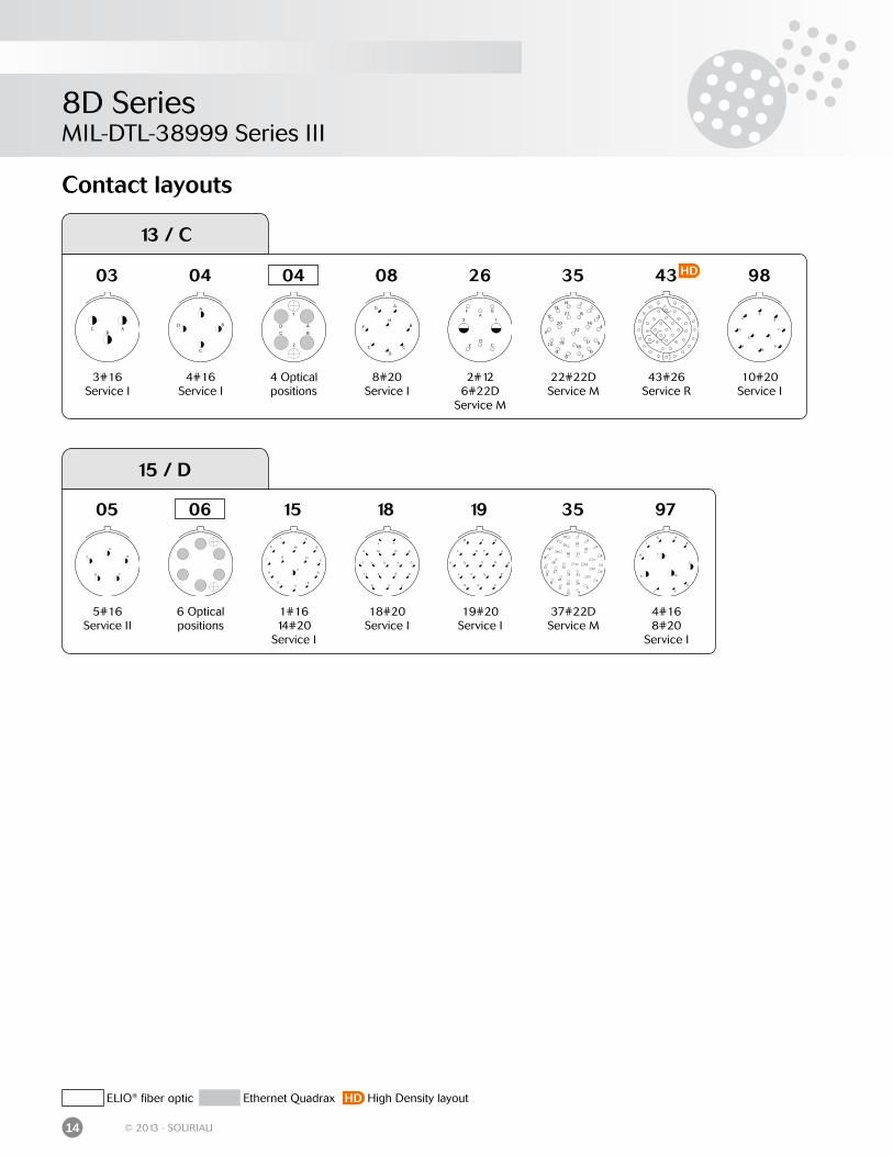
Contact layouts
Contact #26 & #22D
Contact #20
Contact #16
Contact #12
Contact #10
Contact #8 Coax or Concentric Twinax - consult us, Concentric Twinax = Triax
Contact #8 Power
Contact #8 Quadrax
Contact ELIO® (fiber optic)
Contact #4 Power
ELIO® fiber optic Ethernet Quadrax High Density layout Note: Concentric Twinax = TriaxHD
35
6#22DService M
09 / A
1 Optical position
01
1#8 Quadrax
12
12#26Service R
05 98
3#20Service I
HD
01
1#12Service IIall series
excepted JVS
26
26#26Service R
01 02 04 05 12 2202
1#8 CoaxService I
only for JVS
2#16Service I
2 Optical positions
4#20Service I
5#20Service I
1#12Service II
only for JVS
4#22DService M
11 / B
35 80 98 9981
13#22DService M
1#8 Concentric Twinax
Service I
1#8 Quadrax 6#20Service I
7#20Service I
80Spec 251
1#8 Power
HD
8D SeriesMIL-DTL-38999 Series III
14 © 2013 - SOURIAU
Contact layouts
13 / C
03 04 08 26 35 4304
3#16Service I
4#16Service I
4 Optical positions
8#20Service I
2#126#22D
Service M
22#22DService M
43#26Service R
98
10#20Service I
HD
15 / D
5#16Service II
05
6 Optical positions
1#1614#20
Service I
18
18#20Service I
19
19#20Service I
35 97
37#22DService M
4#168#20
Service I
1506
ELIO® fiber optic Ethernet Quadrax High Density layoutHD
8D SeriesMIL-DTL-38999 Series III
15© 2013 - SOURIAU
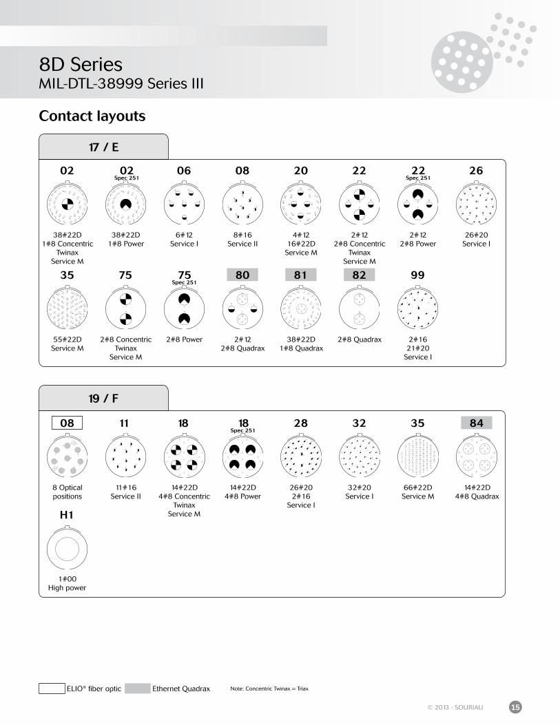
Contact layouts
19 / F
181108
8 Optical positions
11#16Service II
14#22D4#8 Concentric
TwinaxService M
18Spec 251
28 32 35
14#22D4#8 Power
26#202#16
Service I
32#20Service I
66#22DService M
14#22D4#8 Quadrax
84
H1
1#00High power
17 / E
02 22
35 75
38#22D1#8 Concentric
TwinaxService M
2#122#8 Concentric
TwinaxService M
55#22DService M
2#8 Concentric Twinax
Service M
9982
2#122#8 Quadrax
38#22D1#8 Quadrax
2#8 Quadrax 2#1621#20
Service I
818075Spec 251
2#8 Power
22Spec 251
26
2#122#8 Power
26#20Service I
02Spec 251
06 08
38#22D1#8 Power
6#12Service I
8#16Service II
4#1216#22DService M
20
ELIO® fiber optic Ethernet Quadrax Note: Concentric Twinax = Triax
8D SeriesMIL-DTL-38999 Series III
16 © 2013 - SOURIAU
86
23 / H
6#8 Concentric Twinax
Service M
06
21#16Service II
32#20Service I
35
100#22DService M
53
53#20Service I
54 55
4#12, 9#1640#22DService M
55#20Service I
21 32
6#8 PowerService M
06Spec 251
6#8 Quadrax
H1
1#000High power
Contact layouts
21 / G
17#22D2#8 Quadrax
78
11#12Service I
12 Optical positions
11
42
2#4 PowerService I
4#8 Quadrax
84
18#202#8 Quadrax
80
48
4#8 PowerService I
55#22D4#12
Service M
6#16 2#4 PowerService I
75
4#8 Concentric Twinax
Service M
59 72 75Spec 251
4#8 Power
77
17#22D2#8 Concentric
TwinaxService M
77Spec 251
17#22D2#8 Power
16#16Service II
20
18#202#8 Concentric
TwinaxService M
16 20Spec 251
18#202#8 Power
35
79#22DService M
39 41
2#1637#20
Service I
41#20Service I
12
ELIO® fiber optic Ethernet Quadrax Note: Concentric Twinax = Triax
8D SeriesMIL-DTL-38999 Series III
17© 2013 - SOURIAU
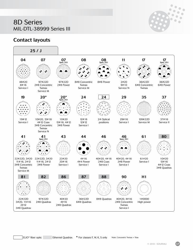
Contact layouts
25 / J
48#208#16
Service I
97#22D2#8 Concentric
TwinaxService M
19
19#12Service I
04 07
20*
10#20, 13#164#12 Coax
3#8 Concentric Twinax
Service N
24 Opticalpositions
29#16Service I
37
37#16Service II
41
22#22D, 3#2011#16, 2#12
3#8 Concentric Twinax
Service M
43 44
23#2020#16
Service I
4#164#4 PowerService I
29
46
40#20, 4#162#8 CoaxService I
10#20 13#16
4#12 Coax3#8 Quadrax
22#22D 3#20, 11#16
2#123#8 Quadrax
97#22D2#8 Quadrax
40#204#16
2#8 Quadrax
36#22D6#8 Quadrax
8#8 Quadrax
90
40#20, 4#162#8 Concentric
TwinaxService I
80
81 82 86 87 88
128#22DService M
35
61#20Service I
61
24
46Spec 251
40#20, 4#162#8 PowerService I
41Spec 251
22#22D, 3#2011#16, 2#123#8 Power
20*Spec 251
24
10#2013#16, 4#123#8 Power
12#1612#12
Service I
97#22D2#8 Power
08
8#8 Concentric Twinax
Service M
07Spec 251
08Spec 251
8#8 Power
11
2#209#10
Service N
17
36#22D6#8 Concentric
Twinax
17Spec 251
36#22D6#8 Power
H1
1#0000High power
ELIO® fiber optic Ethernet Quadrax * For classes F, W, K, S only Note: Concentric Twinax = Triax
8D SeriesMIL-DTL-38999 Series III
18 © 2013 - SOURIAU
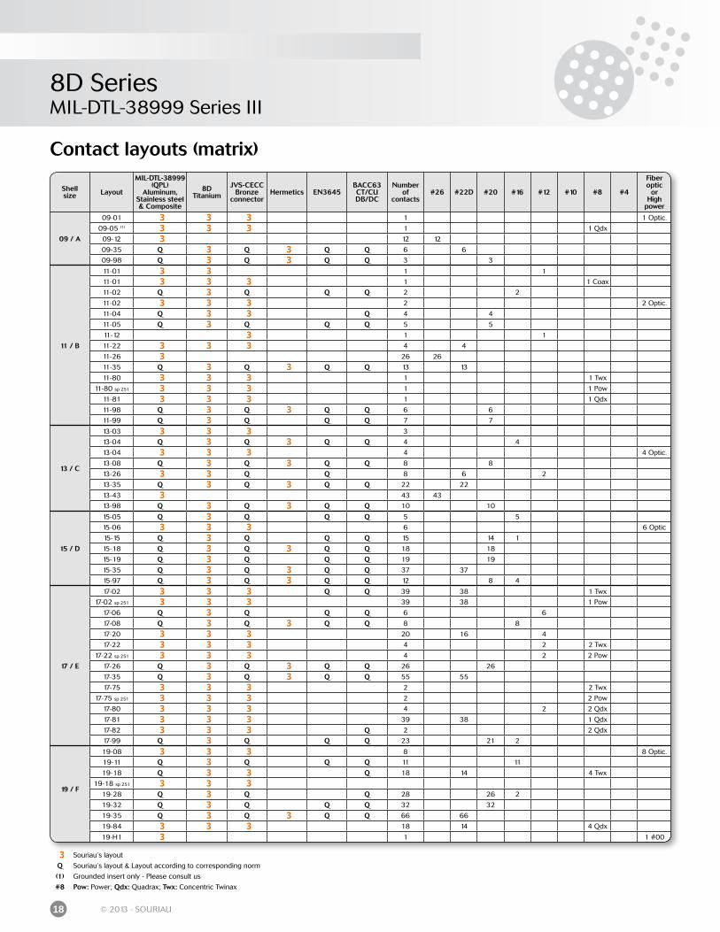
Contact layouts (matrix)
3 Souriau’s layout
Q Souriau’s layout & Layout according to corresponding norm
(1) Grounded insert only - Please consult us
#8 Pow: Power; Qdx: Quadrax; Twx: Concentric Twinax
Shellsize Layout
MIL-DTL-38999(QPL)
Aluminum, Stainless steel& Composite
8DTitanium
JVS-CECC Bronze
connectorHermetics EN3645
BACC63CT/CUDB/DC
Numberof
contacts#26 #22D #20 #16 #12 #10 #8 #4
Fiber optic
orHigh
power
09 / A
09-01 3 3 3 1 1 Optic.
09-05 (1) 3 3 3 1 1 Qdx
09-12 3 12 12
09-35 Q 3 Q 3 Q Q 6 6
09-98 Q 3 Q 3 Q Q 3 3
11 / B
11-01 3 3 1 1
11-01 3 3 3 1 1 Coax
11-02 Q 3 Q Q Q 2 2
11-02 3 3 3 2 2 Optic.
11-04 Q 3 3 Q 4 4
11-05 Q 3 Q Q Q 5 5
11-12 3 1 1
11-22 3 3 3 4 4
11-26 3 26 26
11-35 Q 3 Q 3 Q Q 13 13
11-80 3 3 3 1 1 Twx
11-80 sp 251 3 3 3 1 1 Pow
11-81 3 3 3 1 1 Qdx
11-98 Q 3 Q 3 Q Q 6 6
11-99 Q 3 Q Q Q 7 7
13 / C
13-03 3 3 3 3
13-04 Q 3 Q 3 Q Q 4 4
13-04 3 3 3 4 4 Optic.
13-08 Q 3 Q 3 Q Q 8 8
13-26 3 3 Q Q 8 6 2
13-35 Q 3 Q 3 Q Q 22 22
13-43 3 43 43
13-98 Q 3 Q 3 Q Q 10 10
15 / D
15-05 Q 3 Q Q Q 5 5
15-06 3 3 3 6 6 Optic
15-15 Q 3 Q Q Q 15 14 1
15-18 Q 3 Q 3 Q Q 18 18
15-19 Q 3 Q Q Q 19 19
15-35 Q 3 Q 3 Q Q 37 37
15-97 Q 3 Q 3 Q Q 12 8 4
17 / E
17-02 3 3 3 Q Q 39 38 1 Twx
17-02 sp 251 3 3 3 39 38 1 Pow
17-06 Q 3 Q Q Q 6 6
17-08 Q 3 Q 3 Q Q 8 8
17-20 3 3 3 20 16 4
17-22 3 3 3 4 2 2 Twx
17-22 sp 251 3 3 3 4 2 2 Pow
17-26 Q 3 Q 3 Q Q 26 26
17-35 Q 3 Q 3 Q Q 55 55
17-75 3 3 3 2 2 Twx
17-75 sp 251 3 3 3 2 2 Pow
17-80 3 3 3 4 2 2 Qdx
17-81 3 3 3 39 38 1 Qdx
17-82 3 3 3 Q 2 2 Qdx
17-99 Q 3 Q Q Q 23 21 2
19 / F
19-08 3 3 3 8 8 Optic.
19-11 Q 3 Q Q Q 11 11
19-18 Q 3 3 Q 18 14 4 Twx
19-18 sp 251 3 3 319-28 Q 3 Q Q 28 26 2
19-32 Q 3 Q Q Q 32 32
19-35 Q 3 Q 3 Q Q 66 66
19-84 3 3 3 18 14 4 Qdx
19-H1 3 1 1 #00
8D SeriesMIL-DTL-38999 Series III
19© 2013 - SOURIAU
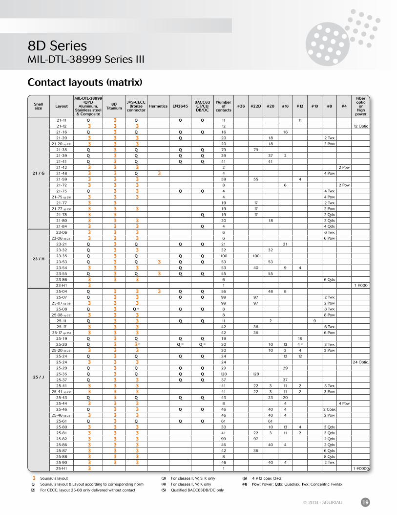
Contact layouts (matrix)
3 Souriau’s layout (3) For classes F, W, S, K only (6) 4 #12 coax (2+2)
Q Souriau’s layout & Layout according to corresponding norm (4) For classes F, W, K only #8 Pow: Power; Qdx: Quadrax; Twx: Concentric Twinax
(2) For CECC, layout 25-08 only delivered without contact (5) Qualified BACC63DB/DC only
Shellsize Layout
MIL-DTL-38999(QPL)
Aluminum, Stainless steel& Composite
8DTitanium
JVS-CECC Bronze
connectorHermetics EN3645
BACC63CT/CUDB/DC
Numberof
contacts#26 #22D #20 #16 #12 #10 #8 #4
Fiber optic
orHigh
power
21 / G
21-11 Q 3 Q Q Q 11 11
21-12 3 3 3 12 12 Optic
21-16 Q 3 Q Q Q 16 16
21-20 3 3 3 Q 20 18 2 Twx
21-20 sp 251 3 3 3 20 18 2 Pow
21-35 Q 3 Q Q Q 79 79
21-39 Q 3 Q Q Q 39 37 2
21-41 Q 3 Q Q Q 41 41
21-42 3 3 3 2 2 Pow
21-48 3 3 Q 3 4 4 Pow
21-59 3 3 3 59 55 4
21-72 3 3 3 8 6 2 Pow
21-75 Q 3 3 Q Q 4 4 Twx
21-75 sp 251 3 3 3 4 4 Pow
21-77 3 3 19 17 2 Twx
21-77 sp 251 3 3 3 19 17 2 Pow
21-78 3 3 Q 19 17 2 Qdx
21-80 3 3 3 20 18 2 Qdx
21-84 3 3 3 Q 4 4 Qdx
23 / H
23-06 3 3 3 6 6 Twx
23-06 sp 251 3 3 3 6 6 Pow
23-21 Q 3 Q Q Q 21 21
23-32 Q 3 3 32 32
23-35 Q 3 Q Q Q 100 100
23-53 Q 3 Q 3 Q Q 53 53
23-54 3 3 3 Q 53 40 9 4
23-55 Q 3 Q 3 Q Q 55 55
23-86 3 3 3 6 6 Qdx
23-H1 3 1 1 #000
25 / J
25-04 Q 3 3 3 Q Q 56 48 8
25-07 Q 3 3 Q Q 99 97 2 Twx
25-07 sp 251 3 3 3 99 97 2 Pow
25-08 Q 3 Q (2) Q Q 8 8 Twx
25-08 sp 251 3 3 3 8 8 Pow
25-11 Q 3 3 Q Q 11 2 9
25-17 3 3 3 42 36 6 Twx
25-17 sp 251 3 3 3 42 36 6 Pow
25-19 Q 3 Q Q Q 19 19
25-20 Q 3 3 3) Q (4) Q (5) 30 10 13 4 6) 3 Twx
25-20 sp 251 3 3 3 30 10 3 4 3 Pow
25-24 Q 3 Q Q Q 24 12 12
25-24 3 3 3 24 24 Optic.
25-29 Q 3 Q Q Q 29 29
25-35 Q 3 Q Q Q 128 128
25-37 Q 3 3 Q Q 37 37
25-41 3 3 3 41 22 3 11 2 3 Twx
25-41 sp 251 3 3 3 41 22 3 11 2 3 Pow
25-43 Q 3 Q Q Q 43 23 20
25-44 3 3 3 8 4 4 Pow
25-46 Q 3 3 Q Q 46 40 4 2 Coax
25-46 sp 251 3 3 3 46 40 4 2 Pow
25-61 Q 3 Q Q Q 61 61
25-80 3 3 3 30 10 13 4 3 Qdx
25-81 3 3 3 41 22 3 11 2 3 Qdx
25-82 3 3 3 99 97 2 Qdx
25-86 3 3 3 46 40 4 2 Qdx
25-87 3 3 3 42 36 6 Qdx
25-88 3 3 3 8 8 Qdx
25-90 3 3 3 46 40 4 2 Twx
25-H1 3 1 1 #0000

8D Series
Standard Series8D Series
Aluminum Series .............................................................................................................................
Composite Series ............................................................................................................................
Stainless Steel Series .....................................................................................................................
Titanium Series .................................................................................................................................
Bronze Series ....................................................................................................................................
22
36
42
48
53
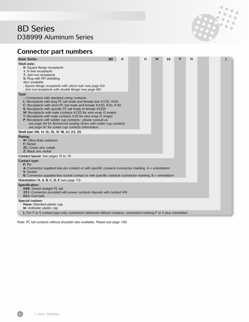
8D SeriesD38999 Aluminum Series
22 © 2013 - SOURIAU
Connector part numbersBasic Series 8D 0 - 11 W 35 P N LShell style: 0: Square flange receptacle 1: In line receptacle 7: Jam nut receptacle 5: Plug with RFI shielding Also available: . Square flange receptacle with clinch nuts (see page 93) . Jam nut receptacle with double flange (see page 96)
Type: -: Connectors with standard crimp contacts. L: Receptacle with long PC tail (male and female size #22D, #20). C: Receptacle with short PC tail (male and female #22D, #20, #16). S: Receptacle with specific PC tail (male et female #22D) W: Receptacle with male contacts #22D for wire wrap (3 wraps) T: Receptacle with male contacts #20 for wire wrap (2 wraps) P: Receptacle with solder cup contacts - please consult us . see page 84 for Reinforced sealing Series with solder cup contacts . see page 67 for solder cup contacts information
Shell size: 09, 11, 13, 15, 17, 19, 21, 23, 25Plating: W: Olive drab cadmium F: Nickel ZC: Green zinc cobalt Z: Black zinc nickel
Contact layout: See pages 13 to 19
Contact type: P: Pin A: Connector supplied less pin contact or with specific contacts (connector marking: A + orientation) S: Socket B: Connector supplied less socket contact or with specific contacts (connector marking: B + orientation)
Orientation: N, A, B, C, D, E (see page 73)
Specification: 046: Tinned straight PC tail 251: Connector provided with power contacts (layouts with contact #8) 022: Fuel tank
Special custom: None: Standard plastic cap M: Antistatic plastic cap
L: For P or S contact type only, connectors delivered without contacts, connectors marking P or S plus orientation
Note: PC tail contacts without shoulder also available. Please see page 100.
8D SeriesD38999 Aluminum Series
23© 2013 - SOURIAU
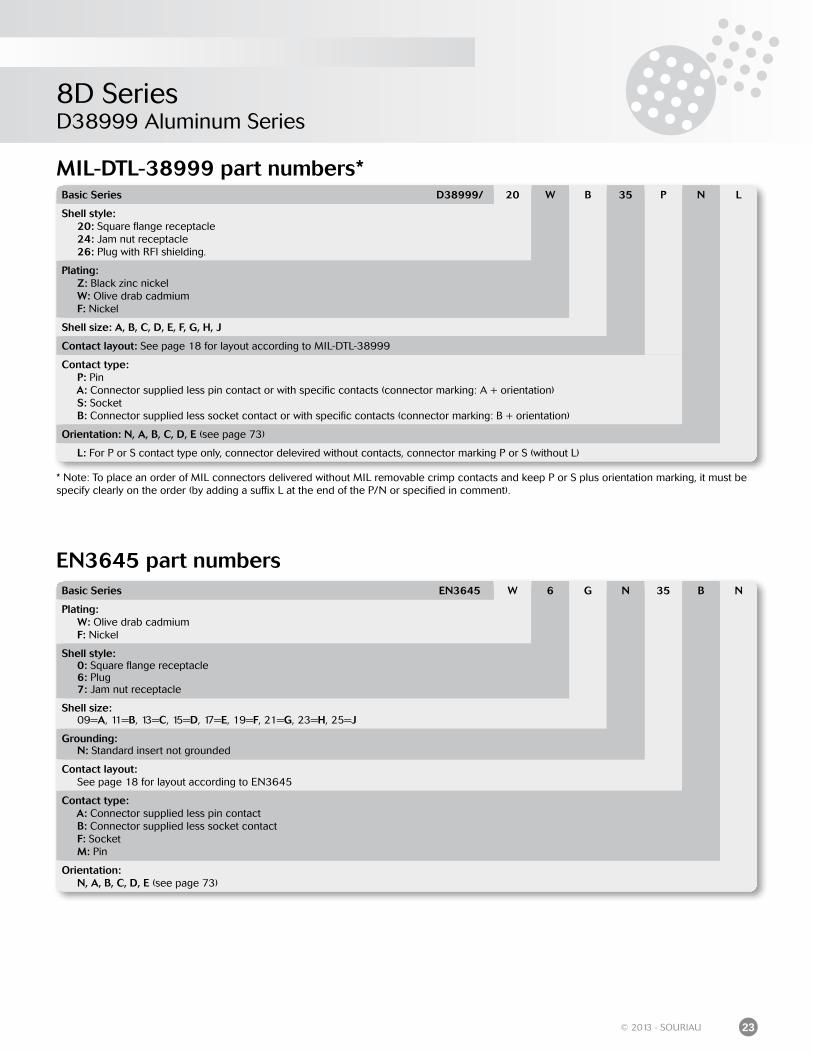
MIL-DTL-38999 part numbers*
* Note: To place an order of MIL connectors delivered without MIL removable crimp contacts and keep P or S plus orientation marking, it must be specify clearly on the order (by adding a suffix L at the end of the P/N or specified in comment).
Basic Series D38999/ 20 W B 35 P N L
Shell style: 20: Square flange receptacle 24: Jam nut receptacle 26: Plug with RFI shielding.
Plating: Z: Black zinc nickel W: Olive drab cadmium F: Nickel
Shell size: A, B, C, D, E, F, G, H, J
Contact layout: See page 18 for layout according to MIL-DTL-38999
Contact type: P: Pin A: Connector supplied less pin contact or with specific contacts (connector marking: A + orientation) S: Socket B: Connector supplied less socket contact or with specific contacts (connector marking: B + orientation)
Orientation: N, A, B, C, D, E (see page 73)
L: For P or S contact type only, connector delevired without contacts, connector marking P or S (without L)
EN3645 part numbersBasic Series EN3645 W 6 G N 35 B N
Plating: W: Olive drab cadmium F: Nickel
Shell style: 0: Square flange receptacle 6: Plug 7: Jam nut receptacle
Shell size: 09=A, 11=B, 13=C, 15=D, 17=E, 19=F, 21=G, 23=H, 25=J
Grounding: N: Standard insert not grounded
Contact layout: See page 18 for layout according to EN3645
Contact type: A: Connector supplied less pin contact B: Connector supplied less socket contact F: Socket M: Pin
Orientation: N, A, B, C, D, E (see page 73)
8D SeriesD38999 Aluminum Series
24 © 2013 - SOURIAU
Dimensions
Receptacle type 0
Receptacle type 7
Recommended coupling torque on panel for jam nut receptacle (type 7)
Shell 09 (A) 11 (B) 13 (C) 15 (D) 17 (E) 19 (F) 21 (G) 23 (H) 25 (J)
Coupling torque(±0.5 N.m)
4 5 7 8 9 10 12 13 14
Note: All dimensions are in millimeters (mm)
Shell size
A±0.15 B Max C Max D Thread E Max F±0.4 ØG Max
09 (A) 16.53
9.9 3.2
M12 x 1-6g 23 27 30.5
11 (B) 19.07 M15 x 1-6g 26 31.8 35.2
13 (C) 23.82 M18 x 1-6g 31 34.9 38.4
15 (D) 26.97 M22 x 1-6g 34 38.1 41.6
17 (E) 30.15 M25 x 1-6g 37 41.3 44.8
19 (F) 33.32 M28 x 1-6g 41 46 49.5
21 (G) 36.50 M31 x 1-6g 46 49.2 52.7
23 (H) 39.67 M34 x 1-6g 47 52.4 55.9
25 (J) 42.85 M37 x 1-6g 51.23 55.6 59
Shell size
A Max B Max C Max D Thread E±0.3 F G H±0.2 J±0.2
09 (A)
20.9 10.72 2.5
M12 x 1-6g 23.8 18.26 15.09
3.25
5.49
11 (B) M15 x 1-6g 26.2 20.62 18.264.93
13 (C) M18 x 1-6g 28.6 23.01 20.62
15 (D) M22 x 1-6g 31 24.61 23.01 4.4
17 (E) M25 x 1-6g 33.3 26.97 24.61
4.9319 (F) M28 x 1-6g 36.5 29.36 26.97
21 (G)
20.07 11.54 3.2
M31 x 1-6g 39.7 31.75 29.36
23 (H) M34 x 1-6g 42.9 34.93 31.753.91 6.15
25 (J) M37 x 1-6g 46 38.1 34.93
A B
CD
EFG
H
J
A
BC
D
EF
ØG
22.6 Max

8D SeriesD38999 Aluminum Series
25© 2013 - SOURIAU
In line receptacle type 1 Plug type 5
Mated connectors dimensions
31.45 Maxi
Thread
ØA
Note: All dimensions are in millimeters (mm)
Shell size Thread ØA
09 (A) M12 x 1-6g 15.90
11 (B) M15 x 1-6g 19.05
13 (C) M18 x 1-6g 22.25
15 (D) M22 x 1-6g 25.40
17 (E) M25 x 1-6g 30.15
19 (F) M28 x 1-6g 31.75
21 (G) M31 x 1-6g 34.75
23 (H) M34 x 1-6g 37.10
25 (J) M37 x 1-6g 41.30
Shell size A Max Thread ØB Max
09 (A)
31.00
M12 x 1-6g 21.80
11 (B) M15 x 1-6g 25.00
13 (C) M18 x 1-6g 29.40
15 (D) M22 x 1-6g 32.50
17 (E) M25 x 1-6g 35.70
19 (F) M28 x 1-6g 38.50
21 (G) M31 x 1-6g 41.70
23 (H) M34 x 1-6g 44.90
25 (J) M37 x 1-6g 48.00
Shell size A Max B Max C Max D Max
09 (A)
37.00 52.30
38.30 53.6011 (B)
13 (C)
38.50 53.80
15 (D)
17 (E)
19 (F)
21 (G)
36.00 51.3023 (H)
25 (J)
A ØB
Thread
Type 0 with plug Type 7 with plug
A
B
C
D

8D SeriesD38999 Aluminum Series
26 © 2013 - SOURIAU
Receptacle with straight PC tail contacts
M: Male contact F: Female contact L: Long PC tail C: Short PC tail S: Specific PC tail Dimensions in millimeters
Shell size09 (A) 11 (B) 13 (C) 15 (C) 17 (E) 19 (F) 21 (G) 23 (H) 25 (J)
Contact size Contact type PC tail type
A
#22D M & F L & C 0.70#22D M & F S 0.50#20 M & F C 0.70#16 M & F C 1.12±0.03
L1
Min #22D M L & C 10.52 10.34Max #22D M L & C 11.46 11.28Min #22D F L & C 10.19 10.01Max #22D F L & C 11.46 11.28Min #22D M S 10.19 10.01Max #22D M S 11.46 11.28Min #22D F S 10.69 10.51Max #22D F S 11.63 11.45Min #20 M C 10.36 10.18Max #20 M C 11.63 11.45Min #20 F C 10.69 10.51Max #20 F C 11.63 11.45Min #16 M C 10.69 10.51Max #16 M C 11.63 11.45Min #16 F C 10.69 10.51Max #16 F C 11.63 11.45
L2
#22D M & F L 8.50#22D M & F C 4.00#22D M & F S 5.10#20 M & F C 5.10#16 M & F C 5±0.1
L3
Min #22D M L & C 9.48 9.59Max #22D M L & C 10.58 10.69Min #22D F L & C 9.15 9.26Max #22D F L & C 10.58 10.69Min #22D M S 9.65 9.76Max #22D M S 10.75 10.86Min #22D F S 9.15 9.26Max #22D F S 10.75 10.86Min #20 M C 9.65 9.76Max #20 M C 10.75 10.86Min #20 F C 9.65 9.76Max #20 F C 10.75 10.86Min #16 M C 9.64 9.75Max #16 M C 10.75 10.86Min #16 F C 9.64 9.75Max #16 F C 10.75 10.86
L1L2
ØA
L3L2
ØA
8D SeriesD38999 Aluminum Series
27© 2013 - SOURIAU
Note: All dimensions are in millimeters (mm)
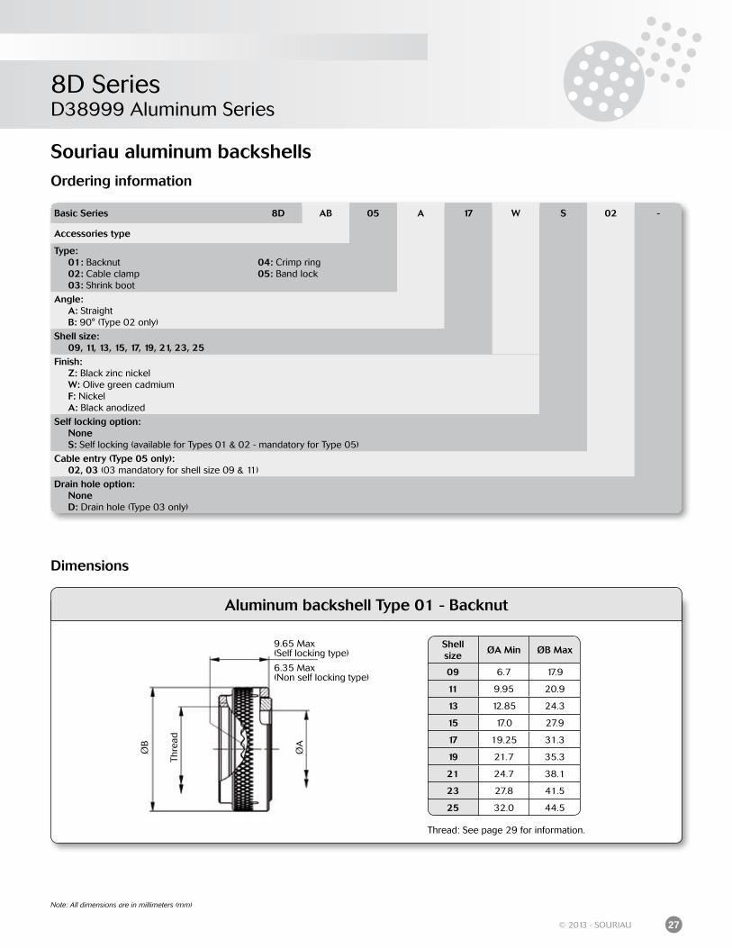
Souriau aluminum backshellsOrdering information
Basic Series 8D AB 05 A 17 W S 02 -
Accessories type
Type: 01: Backnut 02: Cable clamp 03: Shrink boot
04: Crimp ring05: Band lock
Angle: A: Straight B: 90° (Type 02 only)
Shell size: 09, 11, 13, 15, 17, 19, 21, 23, 25Finish: Z: Black zinc nickel W: Olive green cadmium F: Nickel A: Black anodized
Self locking option: None S: Self locking (available for Types 01 & 02 - mandatory for Type 05)
Cable entry (Type 05 only): 02, 03 (03 mandatory for shell size 09 & 11)
Drain hole option: None D: Drain hole (Type 03 only)
Aluminum backshell Type 01 - Backnut
Shellsize
ØA Min ØB Max
09 6.7 17.9
11 9.95 20.9
13 12.85 24.3
15 17.0 27.9
17 19.25 31.3
19 21.7 35.3
21 24.7 38.1
23 27.8 41.5
25 32.0 44.5
9.65 Max(Self locking type)
6.35 Max(Non self locking type)
Thre
ad
ØB
ØA
Thread: See page 29 for information.
Dimensions
8D SeriesD38999 Aluminum Series
28 © 2013 - SOURIAU
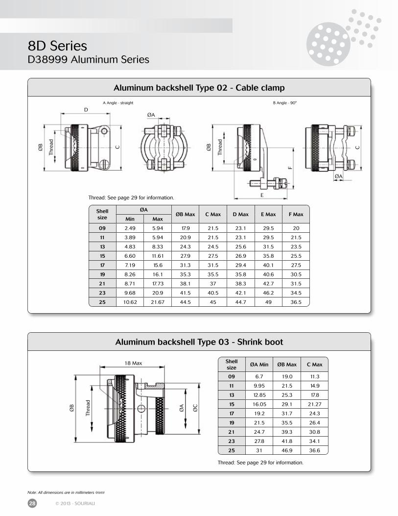
Note: All dimensions are in millimeters (mm)
Aluminum backshell Type 02 - Cable clamp
Shellsize
ØAØB Max C Max D Max E Max F Max
Min Max
09 2.49 5.94 17.9 21.5 23.1 29.5 20
11 3.89 5.94 20.9 21.5 23.1 29.5 21.5
13 4.83 8.33 24.3 24.5 25.6 31.5 23.5
15 6.60 11.61 27.9 27.5 26.9 35.8 25.5
17 7.19 15.6 31.3 31.5 29.4 40.1 27.5
19 8.26 16.1 35.3 35.5 35.8 40.6 30.5
21 8.71 17.73 38.1 37 38.3 42.7 31.5
23 9.68 20.9 41.5 40.5 42.1 46.2 34.5
25 10.62 21.67 44.5 45 44.7 49 36.5
Thre
ad
ØB
ØA
Thre
ad
ØA
ØBC
D
C
F
EThread: See page 29 for information.
A Angle - straight B Angle - 90°
Aluminum backshell Type 03 - Shrink boot
Shellsize
ØA Min ØB Max C Max
09 6.7 19.0 11.3
11 9.95 21.5 14.9
13 12.85 25.3 17.8
15 16.05 29.1 21.27
17 19.2 31.7 24.3
19 21.5 35.5 26.4
21 24.7 39.3 30.8
23 27.8 41.8 34.1
25 31 46.9 36.6
18 Max
Thre
ad
ØB
ØA
ØC
Thread: See page 29 for information.
8D SeriesD38999 Aluminum Series
29© 2013 - SOURIAU
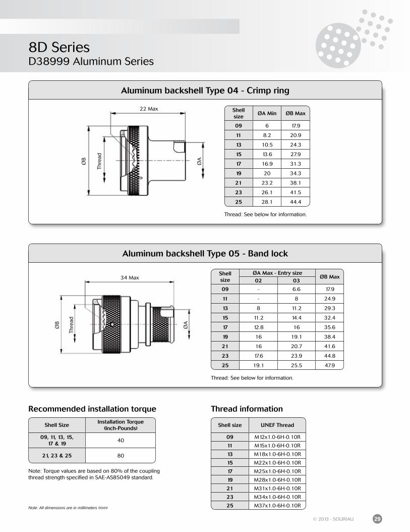
Note: All dimensions are in millimeters (mm)
Aluminum backshell Type 04 - Crimp ring
22 Max
Thre
ad
ØB
ØA
Shellsize
ØA Min ØB Max
09 6 17.9
11 8.2 20.9
13 10.5 24.3
15 13.6 27.9
17 16.9 31.3
19 20 34.3
21 23.2 38.1
23 26.1 41.5
25 28.1 44.4
Thread: See below for information.
Aluminum backshell Type 05 - Band lock
34 Max
Thre
ad
ØB
ØA
Shell size
ØA Max - Entry sizeØB Max
02 03
09 - 6.6 17.9
11 - 8 24.9
13 8 11.2 29.3
15 11.2 14.4 32.4
17 12.8 16 35.6
19 16 19.1 38.4
21 16 20.7 41.6
23 17.6 23.9 44.8
25 19.1 25.5 47.9
Thread: See below for information.
Thread information
Shell size UNEF Thread
09 M12x1.0-6H-0.10R
11 M15x1.0-6H-0.10R
13 M18x1.0-6H-0.10R
15 M22x1.0-6H-0.10R
17 M25x1.0-6H-0.10R
19 M28x1.0-6H-0.10R
21 M31x1.0-6H-0.10R
23 M34x1.0-6H-0.10R
25 M37x1.0-6H-0.10R
Recommended installation torque
Shell SizeInstallation Torque
(Inch-Pounds)
09, 11, 13, 15,17 & 19
40
21, 23 & 25 80
Note: Torque values are based on 80% of the coupling thread strength specified in SAE-AS85049 standard.
8D SeriesD38999 Aluminum Series
30 © 2013 - SOURIAU
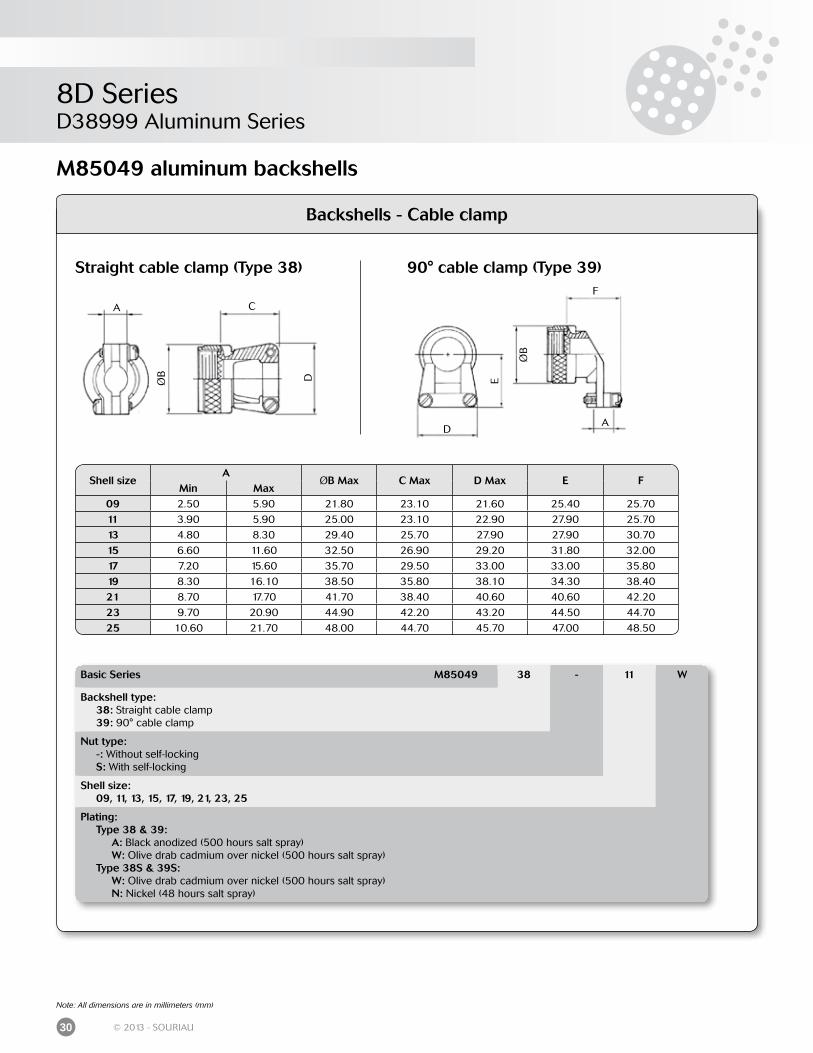
Backshells - Cable clamp
Straight cable clamp (Type 38) 90° cable clamp (Type 39)
A CDØB
A
ØB
D
E
F
Basic Series M85049 38 - 11 W
Backshell type: 38: Straight cable clamp 39: 90° cable clamp
Nut type: -: Without self-locking S: With self-locking
Shell size: 09, 11, 13, 15, 17, 19, 21, 23, 25
Plating: Type 38 & 39: A: Black anodized (500 hours salt spray) W: Olive drab cadmium over nickel (500 hours salt spray) Type 38S & 39S: W: Olive drab cadmium over nickel (500 hours salt spray) N: Nickel (48 hours salt spray)
Shell sizeA
ØB Max C Max D Max E FMin Max
09 2.50 5.90 21.80 23.10 21.60 25.40 25.70
11 3.90 5.90 25.00 23.10 22.90 27.90 25.70
13 4.80 8.30 29.40 25.70 27.90 27.90 30.70
15 6.60 11.60 32.50 26.90 29.20 31.80 32.00
17 7.20 15.60 35.70 29.50 33.00 33.00 35.80
19 8.30 16.10 38.50 35.80 38.10 34.30 38.40
21 8.70 17.70 41.70 38.40 40.60 40.60 42.20
23 9.70 20.90 44.90 42.20 43.20 44.50 44.70
25 10.60 21.70 48.00 44.70 45.70 47.00 48.50
Note: All dimensions are in millimeters (mm)
M85049 aluminum backshells
8D SeriesD38999 Aluminum Series
31© 2013 - SOURIAU
Note: All dimensions are in millimeters (mm)
Backshells for heat shrink boots
Backshell for heat shrink boots(Type 69)
Straight backshell for EMI/RFI heat shrink boots (Type 88)
Basic Series M85049 69 11 A D
Backshell type: 69: Backshell for heat shrink boots 88: Straight backshell for EMI/RFI heat shrink boots
Shell size: 09, 11, 13, 15, 17, 19, 21, 23, 25
Plating: Type 69: A: Black anodised (500 hours salt spray) Type 88: W: Olive drab cadmium N: Nickel
Option (Type 69 only): Empty: Without drain hole D: With drain holeEntry size (Type 88 only): 02: See table above 03: See table above
Shell size ØA Max ØB Max ØC Max
09 19.10 6.35 13.55
11 21.60 9.50 15.40
13 25.40 12.70 19.70
15 29.20 15.90 21.30
17 31.80 19.00 24.50
19 35.60 20.60 26.50
21 39.40 23.80 30.90
23 41.90 27.00 34.40
25 47.00 30.20 36.65
Shell size
ØA MaxØB±0.10 Entry size ØC
02 03 02 0309 21.79 - 6.35 - 10.03
11 24.99 - 7.92 - 11.61
13 29.39 7.92 11.13 11.61 14.81
15 32.49 11.13 14.27 14.81 17.96
17 35.71 12.70 15.88 16.38 19.56
19 38.51 15.88 19.05 19.56 22.73
21 41.71 15.88 20.62 19.56 24.30
23 44.91 17.47 23.83 21.06 27.51
25 47.98 19.05 25.40 22.73 29.08
ØA
ØB
ØC
19.60 Max
ØA
ØB
ØC
40.65 Max
8D SeriesD38999 Aluminum Series
32 © 2013 - SOURIAU
Note: All dimensions are in millimeters (mm)
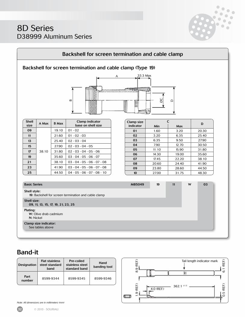
Band-it
DesignationFlat stainless
steel standard band
Pre-coiledstainless steelstandard band
Handbanding tool
Partnumber
8599-9344 8599-9345 8599-9346
8.9
(RE
F.)
1.9
(RE
F.)
6.1
(RE
F.)
0.5
(RE
F.)
4.0 (REF.)362.1 ±1.5
Tail length indicator mark
Backshell for screen termination and cable clamp
B
A 33.3 Max
DØC
Clamp size indicator
CD
Min Max01 1.60 3.20 20.30
02 3.20 6.35 25.40
03 6.35 9.50 27.90
04 7.90 12.70 30.50
05 11.10 15.90 31.80
06 14.30 19.00 35.60
07 17.45 22.20 38.10
08 20.60 24.40 41.90
09 23.80 28.60 44.50
10 27.00 31.75 48.30
Shell size
A Max B MaxClamp indicator
base on shell size
09
38.10
19.10 01 - 02
11 21.60 01 - 02 - 03
13 25.40 02 - 03 - 04
15 27.90 02 - 03 - 04 - 05
17 31.80 02 - 03 - 04 - 05 - 06
19 35.60 03 - 04 - 05 - 06 - 07
21 38.10 03 - 04 - 05 - 06 - 07 - 08
23 41.90 03 - 04 - 05 - 06 - 07 - 08
25 44.50 04 - 05 - 06 - 07 - 08 - 10
Basic Series M85049 19 11 W 03
Shell style: 19: Backshell for screen termination and cable clamp
Shell size: 09, 11, 13, 15, 17, 19, 21, 23, 25
Plating: W: Olive drab cadmium N: Nickel
Clamp size indicator: See tables above
Backshell for screen termination and cable clamp (Type 19)
8D SeriesD38999 Aluminum Series
33© 2013 - SOURIAU
Dimensions
Shell size
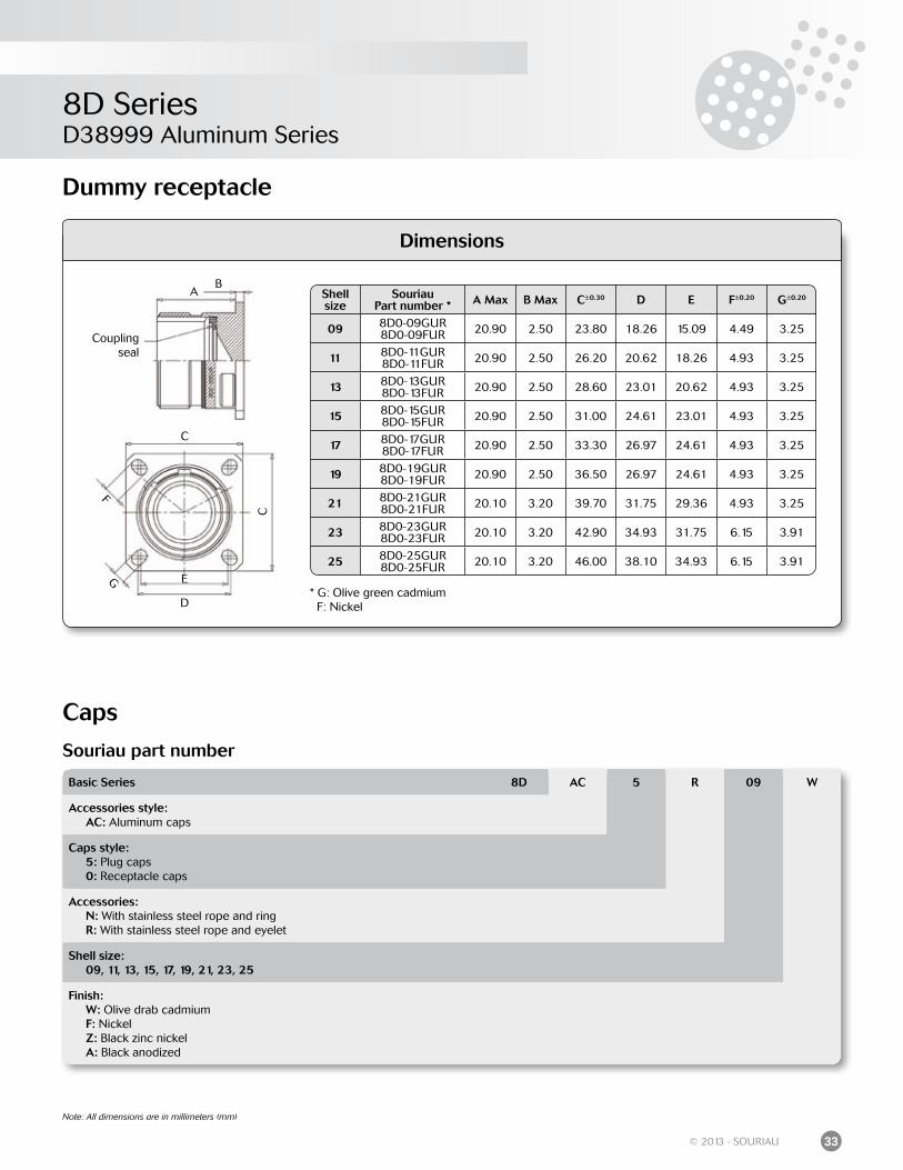
SouriauPart number * A Max B Max C±0.30 D E F±0.20 G±0.20
09 8D0-09GUR8D0-09FUR 20.90 2.50 23.80 18.26 15.09 4.49 3.25
11 8D0-11GUR8D0-11FUR 20.90 2.50 26.20 20.62 18.26 4.93 3.25
13 8D0-13GUR8D0-13FUR 20.90 2.50 28.60 23.01 20.62 4.93 3.25
15 8D0-15GUR8D0-15FUR 20.90 2.50 31.00 24.61 23.01 4.93 3.25
17 8D0-17GUR8D0-17FUR 20.90 2.50 33.30 26.97 24.61 4.93 3.25
19 8D0-19GUR8D0-19FUR 20.90 2.50 36.50 26.97 24.61 4.93 3.25
21 8D0-21GUR8D0-21FUR 20.10 3.20 39.70 31.75 29.36 4.93 3.25
23 8D0-23GUR8D0-23FUR 20.10 3.20 42.90 34.93 31.75 6.15 3.91
25 8D0-25GUR8D0-25FUR 20.10 3.20 46.00 38.10 34.93 6.15 3.91
* G: Olive green cadmium F: Nickel
Note: All dimensions are in millimeters (mm)
Dummy receptacle
Coupling seal
AB
C
C
E
D
F
G
Caps
Basic Series 8D AC 5 R 09 W
Accessories style: AC: Aluminum caps
Caps style: 5: Plug caps 0: Receptacle caps
Accessories: N: With stainless steel rope and ring R: With stainless steel rope and eyelet
Shell size: 09, 11, 13, 15, 17, 19, 21, 23, 25
Finish: W: Olive drab cadmium F: Nickel Z: Black zinc nickel A: Black anodized
Souriau part number
8D SeriesD38999 Aluminum Series
34 © 2013 - SOURIAU
Note: All dimensions are in millimeters (mm)
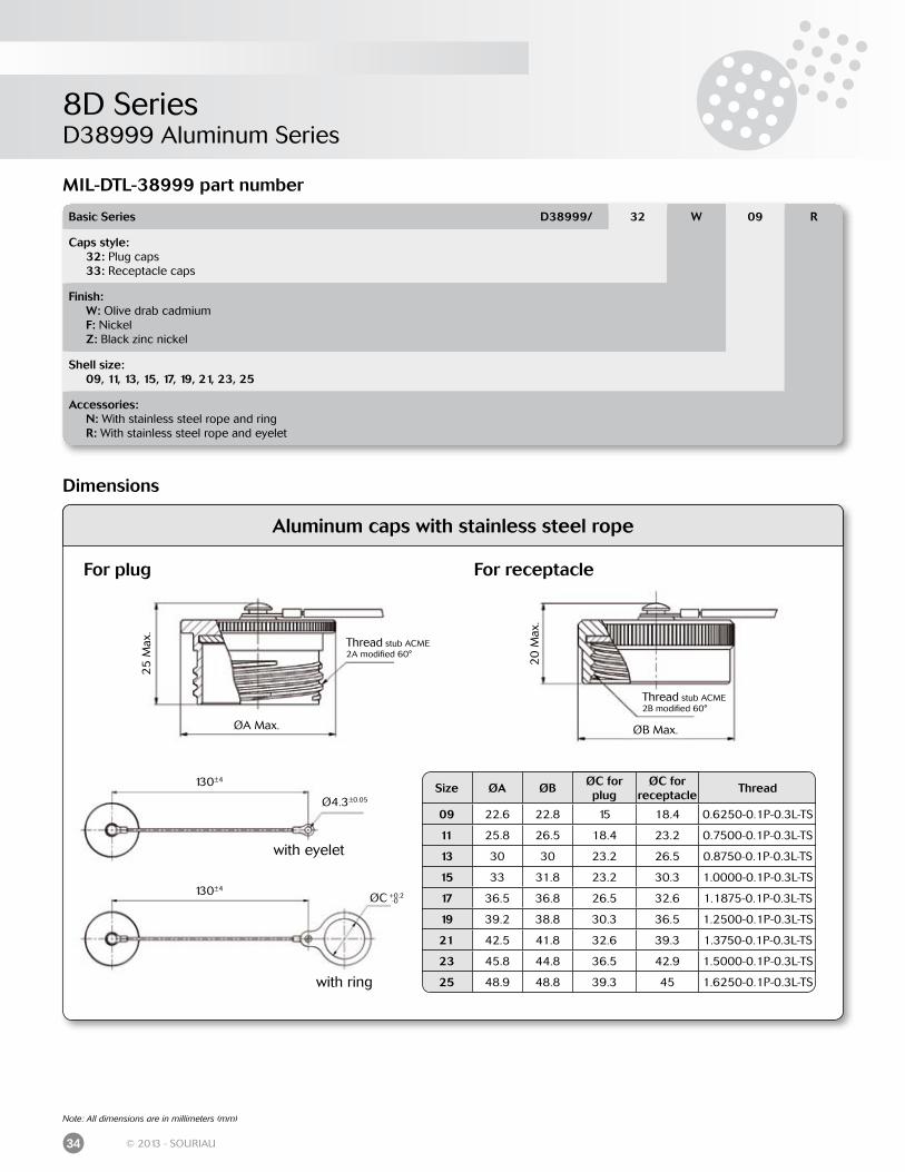
Aluminum caps with stainless steel rope
130±4
130±4
with ring
with eyelet
Ø4.3±0.05
ØC +0.2-0
20
Max
.
ØB Max.
Thread stub ACME 2B modified 60°
25
Max
.
ØA Max.
Thread stub ACME 2A modified 60°
For plug For receptacle
Size ØA ØBØC for plug
ØC forreceptacle
Thread
09 22.6 22.8 15 18.4 0.6250-0.1P-0.3L-TS
11 25.8 26.5 18.4 23.2 0.7500-0.1P-0.3L-TS
13 30 30 23.2 26.5 0.8750-0.1P-0.3L-TS
15 33 31.8 23.2 30.3 1.0000-0.1P-0.3L-TS
17 36.5 36.8 26.5 32.6 1.1875-0.1P-0.3L-TS
19 39.2 38.8 30.3 36.5 1.2500-0.1P-0.3L-TS
21 42.5 41.8 32.6 39.3 1.3750-0.1P-0.3L-TS
23 45.8 44.8 36.5 42.9 1.5000-0.1P-0.3L-TS
25 48.9 48.8 39.3 45 1.6250-0.1P-0.3L-TS
Dimensions
MIL-DTL-38999 part number
Basic Series D38999/ 32 W 09 R
Caps style: 32: Plug caps 33: Receptacle caps
Finish: W: Olive drab cadmium F: Nickel Z: Black zinc nickel
Shell size: 09, 11, 13, 15, 17, 19, 21, 23, 25
Accessories: N: With stainless steel rope and ring R: With stainless steel rope and eyelet
8D SeriesD38999 Aluminum Series
35© 2013 - SOURIAU
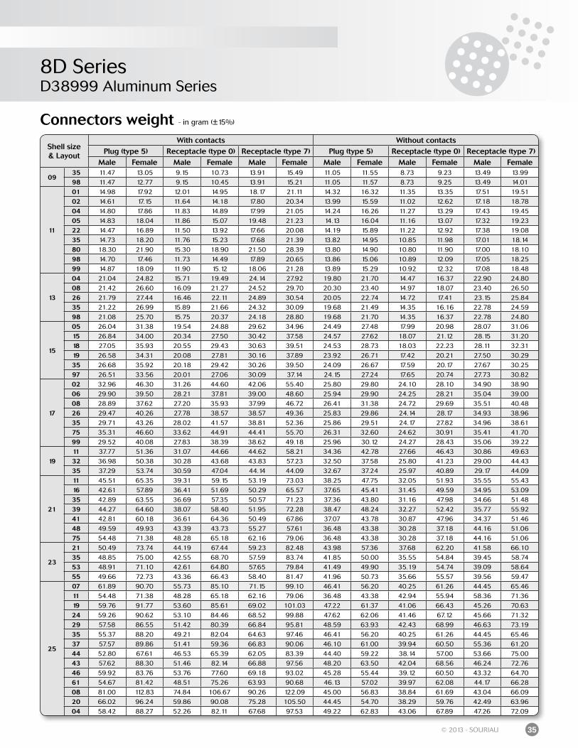
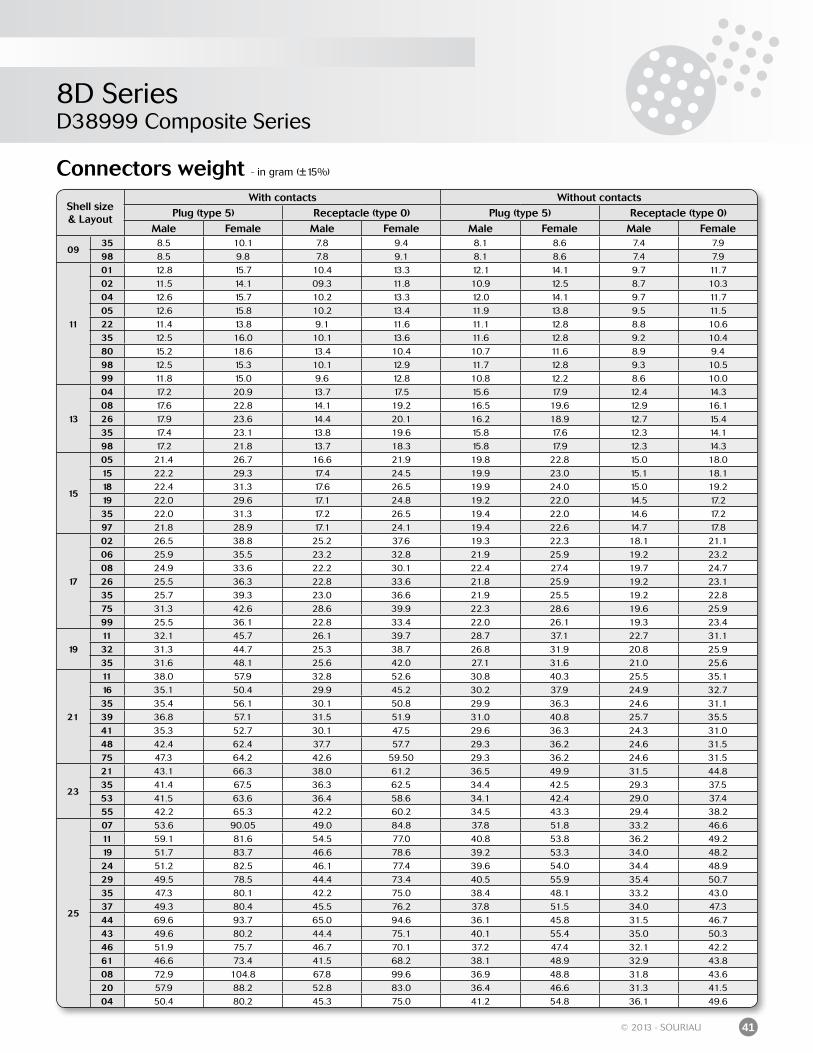
Connectors weight - in gram (±15%)
Shell size& Layout
With contacts Without contactsPlug (type 5) Receptacle (type 0) Receptacle (type 7) Plug (type 5) Receptacle (type 0) Receptacle (type 7)
Male Female Male Female Male Female Male Female Male Female Male Female
0935 11.47 13.05 9.15 10.73 13.91 15.49 11.05 11.55 8.73 9.23 13.49 13.9998 11.47 12.77 9.15 10.45 13.91 15.21 11.05 11.57 8.73 9.25 13.49 14.01
11
01 14.98 17.92 12.01 14.95 18.17 21.11 14.32 16.32 11.35 13.35 17.51 19.5102 14.61 17.15 11.64 14.18 17.80 20.34 13.99 15.59 11.02 12.62 17.18 18.7804 14.80 17.86 11.83 14.89 17.99 21.05 14.24 16.26 11.27 13.29 17.43 19.4505 14.83 18.04 11.86 15.07 19.48 21.23 14.13 16.04 11.16 13.07 17.32 19.2322 14.47 16.89 11.50 13.92 17.66 20.08 14.19 15.89 11.22 12.92 17.38 19.0835 14.73 18.20 11.76 15.23 17.68 21.39 13.82 14.95 10.85 11.98 17.01 18.1480 18.30 21.90 15.30 18.90 21.50 28.39 13.80 14.90 10.80 11.90 17.00 18.1098 14.70 17.46 11.73 14.49 17.89 20.65 13.86 15.06 10.89 12.09 17.05 18.2599 14.87 18.09 11.90 15.12 18.06 21.28 13.89 15.29 10.92 12.32 17.08 18.48
13
04 21.04 24.82 15.71 19.49 24.14 27.92 19.80 21.70 14.47 16.37 22.90 24.8008 21.42 26.60 16.09 21.27 24.52 29.70 20.30 23.40 14.97 18.07 23.40 26.5026 21.79 27.44 16.46 22.11 24.89 30.54 20.05 22.74 14.72 17.41 23.15 25.8435 21.22 26.99 15.89 21.66 24.32 30.09 19.68 21.49 14.35 16.16 22.78 24.5998 21.08 25.70 15.75 20.37 24.18 28.80 19.68 21.70 14.35 16.37 22.78 24.80
15
05 26.04 31.38 19.54 24.88 29.62 34.96 24.49 27.48 17.99 20.98 28.07 31.0615 26.84 34.00 20.34 27.50 30.42 37.58 24.57 27.62 18.07 21.12 28.15 31.2018 27.05 35.93 20.55 29.43 30.63 39.51 24.53 28.73 18.03 22.23 28.11 32.3119 26.58 34.31 20.08 27.81 30.16 37.89 23.92 26.71 17.42 20.21 27.50 30.2935 26.68 35.92 20.18 29.42 30.26 39.50 24.09 26.67 17.59 20.17 27.67 30.2597 26.51 33.56 20.01 27.06 30.09 37.14 24.15 27.24 17.65 20.74 27.73 30.82
17
02 32.96 46.30 31.26 44.60 42.06 55.40 25.80 29.80 24.10 28.10 34.90 38.9006 29.90 39.50 28.21 37.81 39.00 48.60 25.94 29.90 24.25 28.21 35.04 39.0008 28.89 37.62 27.20 35.93 37.99 46.72 26.41 31.38 24.72 29.69 35.51 40.4826 29.47 40.26 27.78 38.57 38.57 49.36 25.83 29.86 24.14 28.17 34.93 38.9635 29.71 43.26 28.02 41.57 38.81 52.36 25.86 29.51 24.17 27.82 34.96 38.6175 35.31 46.60 33.62 44.91 44.41 55.70 26.31 32.60 24.62 30.91 35.41 41.7099 29.52 40.08 27.83 38.39 38.62 49.18 25.96 30.12 24.27 28.43 35.06 39.22
1911 37.77 51.36 31.07 44.66 44.62 58.21 34.36 42.78 27.66 46.43 30.86 49.6332 36.98 50.38 30.28 43.68 43.83 57.23 32.50 37.58 25.80 41.23 29.00 44.4335 37.29 53.74 30.59 47.04 44.14 44.09 32.67 37.24 25.97 40.89 29.17 44.09
21
11 45.51 65.35 39.31 59.15 53.19 73.03 38.25 47.75 32.05 51.93 35.55 55.4316 42.61 57.89 36.41 51.69 50.29 65.57 37.65 45.41 31.45 49.59 34.95 53.0935 42.89 63.55 36.69 57.35 50.57 71.23 37.36 43.80 31.16 47.98 34.66 51.4839 44.27 64.60 38.07 58.40 51.95 72.28 38.47 48.24 32.27 52.42 35.77 55.9241 42.81 60.18 36.61 64.36 50.49 67.86 37.07 43.78 30.87 47.96 34.37 51.4648 49.59 49.93 43.39 43.73 55.27 57.61 36.48 43.38 30.28 37.18 44.16 51.0675 54.48 71.38 48.28 65.18 62.16 79.06 36.48 43.38 30.28 37.18 44.16 51.06
23
21 50.49 73.74 44.19 67.44 59.23 82.48 43.98 57.36 37.68 62.20 41.58 66.1035 48.85 75.00 42.55 68.70 57.59 83.74 41.85 50.00 35.55 54.84 39.45 58.7453 48.91 71.10 42.61 64.80 57.65 79.84 41.49 49.90 35.19 54.74 39.09 58.6455 49.66 72.73 43.36 66.43 58.40 81.47 41.96 50.73 35.66 55.57 39.56 59.47
25
07 61.89 90.70 55.73 85.10 71.15 99.10 46.41 56.20 40.25 61.26 44.45 65.4611 54.48 71.38 48.28 65.18 62.16 79.06 36.48 43.38 42.94 55.94 58.36 71.3619 59.76 91.77 53.60 85.61 69.02 101.03 47.22 61.37 41.06 66.43 45.26 70.6324 59.26 90.62 53.10 84.46 68.52 99.88 47.62 62.06 41.46 67.12 45.66 71.3229 57.58 86.55 51.42 80.39 66.84 95.81 48.59 63.93 42.43 68.99 46.63 73.1935 55.37 88.20 49.21 82.04 64.63 97.46 46.41 56.20 40.25 61.26 44.45 65.4637 57.57 89.86 51.41 59.36 66.83 90.06 46.10 61.00 39.94 60.50 55.36 61.2044 52.80 67.61 46.53 65.39 62.05 83.39 44.40 59.22 38.14 57.00 53.66 75.0043 57.62 88.30 51.46 82.14 66.88 97.56 48.20 63.50 42.04 68.56 46.24 72.7646 59.92 83.76 53.76 77.60 69.18 93.02 45.28 55.44 39.12 60.50 43.32 64.7061 54.67 81.42 48.51 75.26 63.93 90.68 46.13 57.02 39.97 62.08 44.17 66.2808 81.00 112.83 74.84 106.67 90.26 122.09 45.00 56.83 38.84 61.69 43.04 66.0920 66.02 96.24 59.86 90.08 75.28 105.50 44.45 54.70 38.29 59.76 42.49 63.9604 58.42 88.27 52.26 82.11 67.68 97.53 49.22 62.83 43.06 67.89 47.26 72.09
8D SeriesD38999 Composite Series
36 © 2013 - SOURIAU
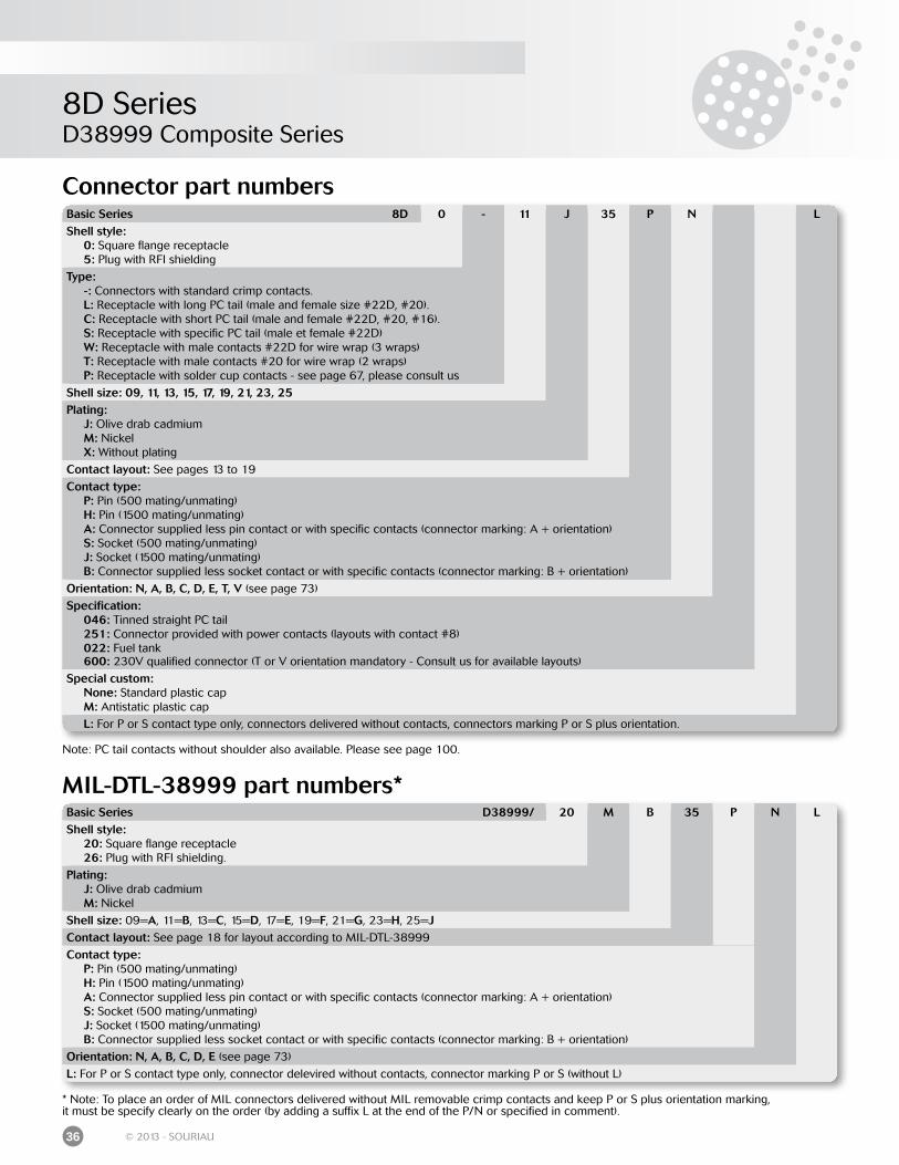
Connector part numbers
MIL-DTL-38999 part numbers*
* Note: To place an order of MIL connectors delivered without MIL removable crimp contacts and keep P or S plus orientation marking,it must be specify clearly on the order (by adding a suffix L at the end of the P/N or specified in comment).
Basic Series 8D 0 - 11 J 35 P N LShell style: 0: Square flange receptacle 5: Plug with RFI shielding
Type: -: Connectors with standard crimp contacts. L: Receptacle with long PC tail (male and female size #22D, #20). C: Receptacle with short PC tail (male and female #22D, #20, #16). S: Receptacle with specific PC tail (male et female #22D) W: Receptacle with male contacts #22D for wire wrap (3 wraps) T: Receptacle with male contacts #20 for wire wrap (2 wraps) P: Receptacle with solder cup contacts - see page 67, please consult us
Shell size: 09, 11, 13, 15, 17, 19, 21, 23, 25Plating: J: Olive drab cadmium M: Nickel X: Without plating
Contact layout: See pages 13 to 19
Contact type: P: Pin (500 mating/unmating) H: Pin (1500 mating/unmating) A: Connector supplied less pin contact or with specific contacts (connector marking: A + orientation) S: Socket (500 mating/unmating) J: Socket (1500 mating/unmating) B: Connector supplied less socket contact or with specific contacts (connector marking: B + orientation)
Orientation: N, A, B, C, D, E, T, V (see page 73)
Specification: 046: Tinned straight PC tail 251: Connector provided with power contacts (layouts with contact #8) 022: Fuel tank 600: 230V qualified connector (T or V orientation mandatory - Consult us for available layouts)
Special custom: None: Standard plastic cap M: Antistatic plastic cap
L: For P or S contact type only, connectors delivered without contacts, connectors marking P or S plus orientation.
Basic Series D38999/ 20 M B 35 P N LShell style: 20: Square flange receptacle 26: Plug with RFI shielding.
Plating: J: Olive drab cadmium M: Nickel
Shell size: 09=A, 11=B, 13=C, 15=D, 17=E, 19=F, 21=G, 23=H, 25=JContact layout: See page 18 for layout according to MIL-DTL-38999
Contact type: P: Pin (500 mating/unmating) H: Pin (1500 mating/unmating) A: Connector supplied less pin contact or with specific contacts (connector marking: A + orientation) S: Socket (500 mating/unmating) J: Socket (1500 mating/unmating) B: Connector supplied less socket contact or with specific contacts (connector marking: B + orientation)
Orientation: N, A, B, C, D, E (see page 73)
L: For P or S contact type only, connector delevired without contacts, connector marking P or S (without L)
Note: PC tail contacts without shoulder also available. Please see page 100.
8D SeriesD38999 Composite Series
37© 2013 - SOURIAU
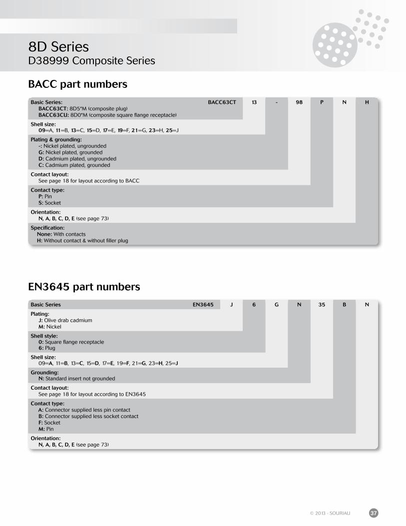
BACC part numbers
EN3645 part numbers
Basic Series: BACC63CT: 8D5*M (composite plug) BACC63CU: 8D0*M (composite square flange receptacle)
BACC63CT 13 - 98 P N H
Shell size: 09=A, 11=B, 13=C, 15=D, 17=E, 19=F, 21=G, 23=H, 25=J
Plating & grounding: -: Nickel plated, ungrounded G: Nickel plated, grounded D: Cadmium plated, ungrounded C: Cadmium plated, grounded
Contact layout: See page 18 for layout according to BACC
Contact type: P: Pin S: Socket
Orientation: N, A, B, C, D, E (see page 73)
Specification: None: With contacts H: Without contact & without filler plug
Basic Series EN3645 J 6 G N 35 B N
Plating: J: Olive drab cadmium M: Nickel
Shell style: 0: Square flange receptacle 6: Plug
Shell size: 09=A, 11=B, 13=C, 15=D, 17=E, 19=F, 21=G, 23=H, 25=J
Grounding: N: Standard insert not grounded
Contact layout: See page 18 for layout according to EN3645
Contact type: A: Connector supplied less pin contact B: Connector supplied less socket contact F: Socket M: Pin
Orientation: N, A, B, C, D, E (see page 73)
8D SeriesD38999 Composite Series
38 © 2013 - SOURIAU
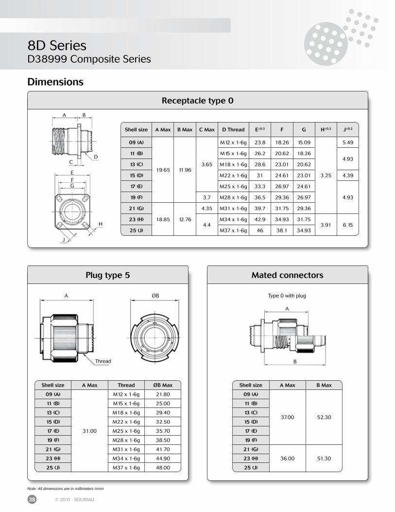
Receptacle type 0
Dimensions
Shell size A Max B Max C Max D Thread E±0.3 F G H±0.2 J±0.2
09 (A)
19.65 11.963.65
M12 x 1-6g 23.8 18.26 15.09
3.25
5.49
11 (B) M15 x 1-6g 26.2 20.62 18.264.93
13 (C) M18 x 1-6g 28.6 23.01 20.62
15 (D) M22 x 1-6g 31 24.61 23.01 4.39
17 (E) M25 x 1-6g 33.3 26.97 24.61
4.9319 (F) 3.7 M28 x 1-6g 36.5 29.36 26.97
21 (G)
18.85 12.76
4.35 M31 x 1-6g 39.7 31.75 29.36
23 (H)4.4
M34 x 1-6g 42.9 34.93 31.753.91 6.15
25 (J) M37 x 1-6g 46 38.1 34.93
Note: All dimensions are in millimeters (mm)
A B
CD
EFG
H
J
Plug type 5 Mated connectors
Shell size A Max Thread ØB Max
09 (A)
31.00
M12 x 1-6g 21.80
11 (B) M15 x 1-6g 25.00
13 (C) M18 x 1-6g 29.40
15 (D) M22 x 1-6g 32.50
17 (E) M25 x 1-6g 35.70
19 (F) M28 x 1-6g 38.50
21 (G) M31 x 1-6g 41.70
23 (H) M34 x 1-6g 44.90
25 (J) M37 x 1-6g 48.00
A ØB
Thread
Shell size A Max B Max
09 (A)
37.00 52.30
11 (B)
13 (C)
15 (D)
17 (E)
19 (F)
21 (G)
36.00 51.3023 (H)
25 (J)
Type 0 with plug
A
B
8D SeriesD38999 Composite Series
39© 2013 - SOURIAU
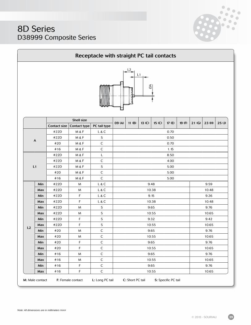
Receptacle with straight PC tail contacts
M: Male contact F: Female contact L: Long PC tail C: Short PC tail S: Specific PC tail
Shell size09 (A) 11 (B) 13 (C) 15 (C) 17 (E) 19 (F) 21 (G) 23 (H) 25 (J)
Contact size Contact type PC tail type
A
#22D M & F L & C 0.70
#22D M & F S 0.50
#20 M & F C 0.70
#16 M & F C 1.15
L1
#22D M & F L 8.50
#22D M & F C 4.00
#22D M & F S 5.00
#20 M & F C 5.00
#16 M & F C 5.00
L2
Min #22D M L & C 9.48 9.59
Max #22D M L & C 10.38 10.48
Min #22D F L & C 9.15 9.26
Max #22D F L & C 10.38 10.48
Min #22D M S 9.65 9.76
Max #22D M S 10.55 10.65
Min #22D F S 9.32 9.42
Max #22D F S 10.55 10.65
Min #20 M C 9.65 9.76
Max #20 M C 10.55 10.65
Min #20 F C 9.65 9.76
Max #20 F C 10.55 10.65
Min #16 M C 9.65 9.76
Max #16 M C 10.55 10.65
Min #16 F C 9.65 9.76
Max #16 F C 10.55 10.65
Note: All dimensions are in millimeters (mm)
L1
L2
ØA
8D SeriesD38999 Composite Series
40 © 2013 - SOURIAU
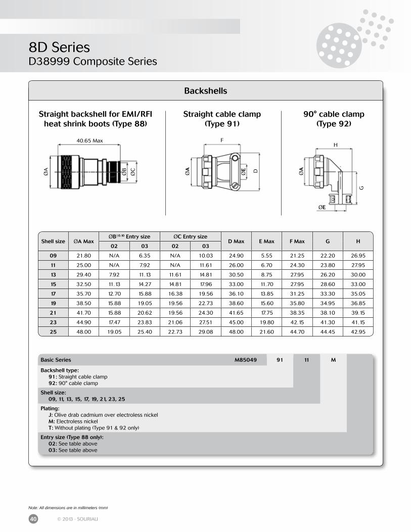
ØA
ØE
H
G
DØE
ØA
F
ØA
ØB
ØC
40.65 Max
Note: All dimensions are in millimeters (mm)
Backshells
Straight cable clamp(Type 91)
90° cable clamp (Type 92)
Basic Series M85049 91 11 M
Backshell type: 91: Straight cable clamp 92: 90° cable clamp
Shell size: 09, 11, 13, 15, 17, 19, 21, 23, 25
Plating: J: Olive drab cadmium over electroless nickel M: Electroless nickel T: Without plating (Type 91 & 92 only)
Entry size (Type 88 only): 02: See table above 03: See table above
Shell size ØA MaxØB±0.10 Entry size ØC Entry size
D Max E Max F Max G H02 03 02 03
09 21.80 N/A 6.35 N/A 10.03 24.90 5.55 21.25 22.20 26.95
11 25.00 N/A 7.92 N/A 11.61 26.00 6.70 24.30 23.80 27.95
13 29.40 7.92 11.13 11.61 14.81 30.50 8.75 27.95 26.20 30.00
15 32.50 11.13 14.27 14.81 17.96 33.00 11.70 27.95 28.60 33.00
17 35.70 12.70 15.88 16.38 19.56 36.10 13.85 31.25 33.30 35.05
19 38.50 15.88 19.05 19.56 22.73 38.60 15.60 35.80 34.95 36.85
21 41.70 15.88 20.62 19.56 24.30 41.65 17.75 38.35 38.10 39.15
23 44.90 17.47 23.83 21.06 27.51 45.00 19.80 42.15 41.30 41.15
25 48.00 19.05 25.40 22.73 29.08 48.00 21.60 44.70 44.45 42.95
Straight backshell for EMI/RFI heat shrink boots (Type 88)
8D SeriesD38999 Composite Series
41© 2013 - SOURIAU
Connectors weight - in gram (±15%)
Shell size& Layout
With contacts Without contactsPlug (type 5) Receptacle (type 0) Plug (type 5) Receptacle (type 0)
Male Female Male Female Male Female Male Female
0935 8.5 10.1 7.8 9.4 8.1 8.6 7.4 7.998 8.5 9.8 7.8 9.1 8.1 8.6 7.4 7.9
11
01 12.8 15.7 10.4 13.3 12.1 14.1 9.7 11.702 11.5 14.1 09.3 11.8 10.9 12.5 8.7 10.304 12.6 15.7 10.2 13.3 12.0 14.1 9.7 11.705 12.6 15.8 10.2 13.4 11.9 13.8 9.5 11.522 11.4 13.8 9.1 11.6 11.1 12.8 8.8 10.635 12.5 16.0 10.1 13.6 11.6 12.8 9.2 10.480 15.2 18.6 13.4 10.4 10.7 11.6 8.9 9.498 12.5 15.3 10.1 12.9 11.7 12.8 9.3 10.599 11.8 15.0 9.6 12.8 10.8 12.2 8.6 10.0
13
04 17.2 20.9 13.7 17.5 15.6 17.9 12.4 14.308 17.6 22.8 14.1 19.2 16.5 19.6 12.9 16.126 17.9 23.6 14.4 20.1 16.2 18.9 12.7 15.435 17.4 23.1 13.8 19.6 15.8 17.6 12.3 14.198 17.2 21.8 13.7 18.3 15.8 17.9 12.3 14.3
15
05 21.4 26.7 16.6 21.9 19.8 22.8 15.0 18.015 22.2 29.3 17.4 24.5 19.9 23.0 15.1 18.118 22.4 31.3 17.6 26.5 19.9 24.0 15.0 19.219 22.0 29.6 17.1 24.8 19.2 22.0 14.5 17.235 22.0 31.3 17.2 26.5 19.4 22.0 14.6 17.297 21.8 28.9 17.1 24.1 19.4 22.6 14.7 17.8
17
02 26.5 38.8 25.2 37.6 19.3 22.3 18.1 21.106 25.9 35.5 23.2 32.8 21.9 25.9 19.2 23.208 24.9 33.6 22.2 30.1 22.4 27.4 19.7 24.726 25.5 36.3 22.8 33.6 21.8 25.9 19.2 23.135 25.7 39.3 23.0 36.6 21.9 25.5 19.2 22.875 31.3 42.6 28.6 39.9 22.3 28.6 19.6 25.999 25.5 36.1 22.8 33.4 22.0 26.1 19.3 23.4
1911 32.1 45.7 26.1 39.7 28.7 37.1 22.7 31.132 31.3 44.7 25.3 38.7 26.8 31.9 20.8 25.935 31.6 48.1 25.6 42.0 27.1 31.6 21.0 25.6
21
11 38.0 57.9 32.8 52.6 30.8 40.3 25.5 35.116 35.1 50.4 29.9 45.2 30.2 37.9 24.9 32.735 35.4 56.1 30.1 50.8 29.9 36.3 24.6 31.139 36.8 57.1 31.5 51.9 31.0 40.8 25.7 35.541 35.3 52.7 30.1 47.5 29.6 36.3 24.3 31.048 42.4 62.4 37.7 57.7 29.3 36.2 24.6 31.575 47.3 64.2 42.6 59.50 29.3 36.2 24.6 31.5
23
21 43.1 66.3 38.0 61.2 36.5 49.9 31.5 44.835 41.4 67.5 36.3 62.5 34.4 42.5 29.3 37.553 41.5 63.6 36.4 58.6 34.1 42.4 29.0 37.455 42.2 65.3 42.2 60.2 34.5 43.3 29.4 38.2
25
07 53.6 90.05 49.0 84.8 37.8 51.8 33.2 46.611 59.1 81.6 54.5 77.0 40.8 53.8 36.2 49.219 51.7 83.7 46.6 78.6 39.2 53.3 34.0 48.224 51.2 82.5 46.1 77.4 39.6 54.0 34.4 48.929 49.5 78.5 44.4 73.4 40.5 55.9 35.4 50.735 47.3 80.1 42.2 75.0 38.4 48.1 33.2 43.037 49.3 80.4 45.5 76.2 37.8 51.5 34.0 47.344 69.6 93.7 65.0 94.6 36.1 45.8 31.5 46.743 49.6 80.2 44.4 75.1 40.1 55.4 35.0 50.346 51.9 75.7 46.7 70.1 37.2 47.4 32.1 42.261 46.6 73.4 41.5 68.2 38.1 48.9 32.9 43.808 72.9 104.8 67.8 99.6 36.9 48.8 31.8 43.620 57.9 88.2 52.8 83.0 36.4 46.6 31.3 41.504 50.4 80.2 45.3 75.0 41.2 54.8 36.1 49.6
8D SeriesD38999 Stainless Steel Series
42 © 2013 - SOURIAU
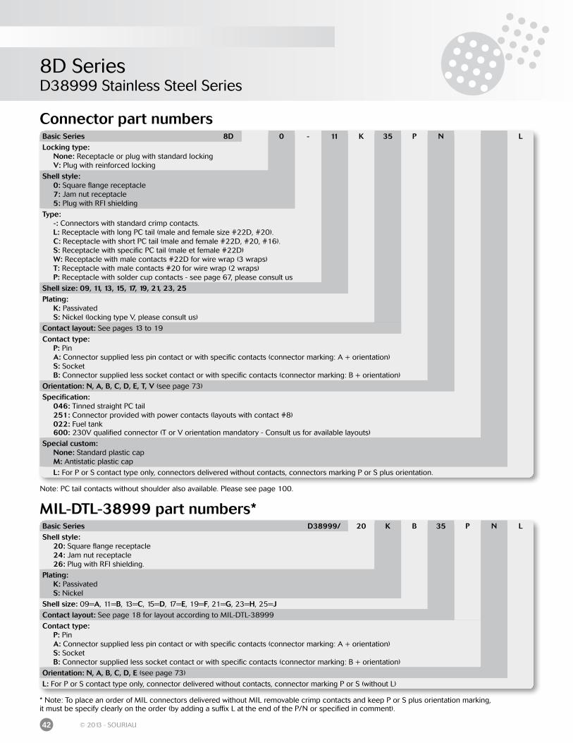
Connector part numbers
MIL-DTL-38999 part numbers*
* Note: To place an order of MIL connectors delivered without MIL removable crimp contacts and keep P or S plus orientation marking,it must be specify clearly on the order (by adding a suffix L at the end of the P/N or specified in comment).
Basic Series 8D 0 - 11 K 35 P N LLocking type: None: Receptacle or plug with standard locking V: Plug with reinforced locking
Shell style: 0: Square flange receptacle 7: Jam nut receptacle 5: Plug with RFI shielding
Type: -: Connectors with standard crimp contacts. L: Receptacle with long PC tail (male and female size #22D, #20). C: Receptacle with short PC tail (male and female #22D, #20, #16). S: Receptacle with specific PC tail (male et female #22D) W: Receptacle with male contacts #22D for wire wrap (3 wraps) T: Receptacle with male contacts #20 for wire wrap (2 wraps) P: Receptacle with solder cup contacts - see page 67, please consult us
Shell size: 09, 11, 13, 15, 17, 19, 21, 23, 25Plating: K: Passivated S: Nickel (locking type V, please consult us)
Contact layout: See pages 13 to 19
Contact type: P: Pin A: Connector supplied less pin contact or with specific contacts (connector marking: A + orientation) S: Socket B: Connector supplied less socket contact or with specific contacts (connector marking: B + orientation)
Orientation: N, A, B, C, D, E, T, V (see page 73)
Specification: 046: Tinned straight PC tail 251: Connector provided with power contacts (layouts with contact #8) 022: Fuel tank 600: 230V qualified connector (T or V orientation mandatory - Consult us for available layouts)
Special custom: None: Standard plastic cap M: Antistatic plastic cap
L: For P or S contact type only, connectors delivered without contacts, connectors marking P or S plus orientation.
Basic Series D38999/ 20 K B 35 P N LShell style: 20: Square flange receptacle 24: Jam nut receptacle 26: Plug with RFI shielding.
Plating: K: Passivated S: Nickel
Shell size: 09=A, 11=B, 13=C, 15=D, 17=E, 19=F, 21=G, 23=H, 25=JContact layout: See page 18 for layout according to MIL-DTL-38999
Contact type: P: Pin A: Connector supplied less pin contact or with specific contacts (connector marking: A + orientation) S: Socket B: Connector supplied less socket contact or with specific contacts (connector marking: B + orientation)
Orientation: N, A, B, C, D, E (see page 73)
L: For P or S contact type only, connector delivered without contacts, connector marking P or S (without L)
Note: PC tail contacts without shoulder also available. Please see page 100.
8D SeriesD38999 Stainless Steel Series
43© 2013 - SOURIAU
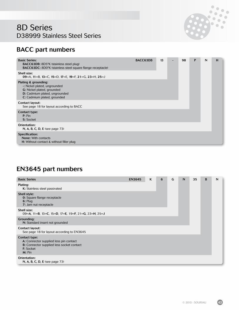
BACC part numbers
EN3645 part numbers
Basic Series EN3645 K 6 G N 35 B N
Plating: K: Stainless steel passivated
Shell style: 0: Square flange receptacle 6: Plug 7: Jam nut receptacle
Shell size: 09=A, 11=B, 13=C, 15=D, 17=E, 19=F, 21=G, 23=H, 25=J
Grounding: N: Standard insert not grounded
Contact layout: See page 18 for layout according to EN3645
Contact type: A: Connector supplied less pin contact B: Connector supplied less socket contact F: Socket M: Pin
Orientation: N, A, B, C, D, E (see page 73)
Basic Series: BACC63DB: 8D5*K (stainless steel plug) BACC63DC: 8D0*K (stainless steel square flange receptacle)
BACC63DB 13 - 98 P N H
Shell size: 09=A, 11=B, 13=C, 15=D, 17=E, 19=F, 21=G, 23=H, 25=J
Plating & grounding: -: Nickel plated, ungrounded G: Nickel plated, grounded D: Cadmium plated, ungrounded C: Cadmium plated, grounded
Contact layout: See page 18 for layout according to BACC
Contact type: P: Pin S: Socket
Orientation: N, A, B, C, D, E (see page 73)
Specification: None: With contacts H: Without contact & without filler plug
8D SeriesD38999 Stainless Steel Series
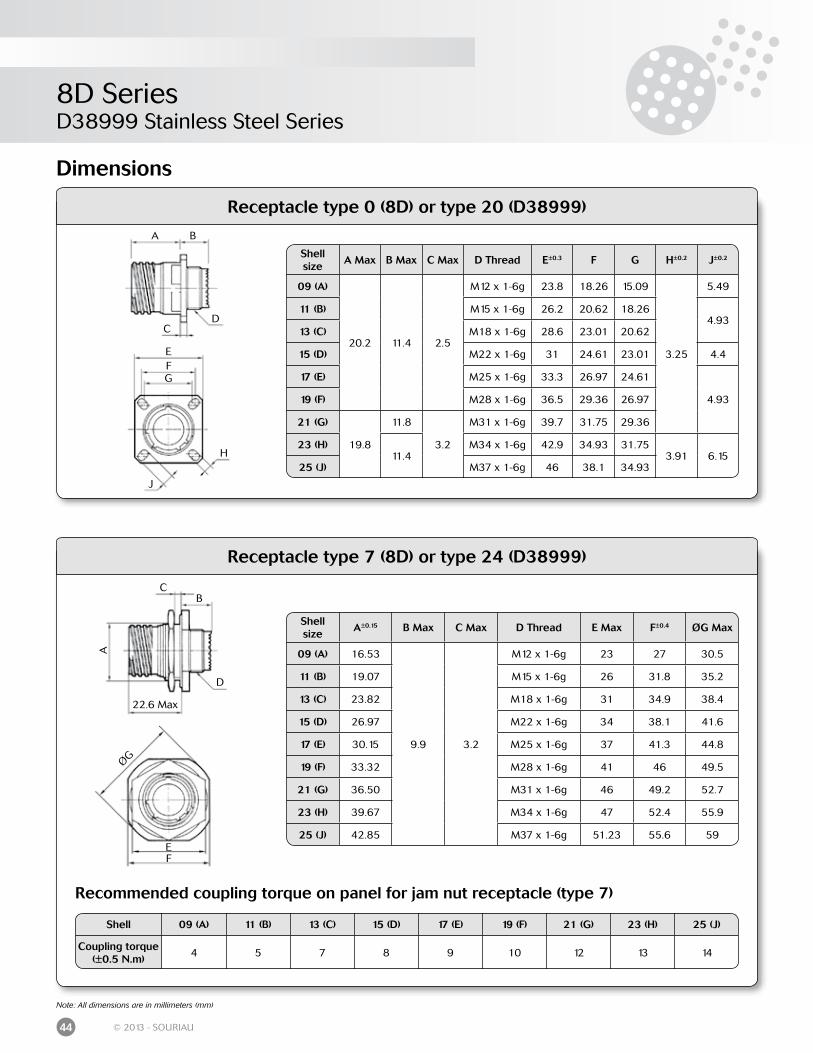
44 © 2013 - SOURIAU
Dimensions
Receptacle type 0 (8D) or type 20 (D38999)
Receptacle type 7 (8D) or type 24 (D38999)
Recommended coupling torque on panel for jam nut receptacle (type 7)
Note: All dimensions are in millimeters (mm)
Shell 09 (A) 11 (B) 13 (C) 15 (D) 17 (E) 19 (F) 21 (G) 23 (H) 25 (J)
Coupling torque(±0.5 N.m)
4 5 7 8 9 10 12 13 14
Shell size
A Max B Max C Max D Thread E±0.3 F G H±0.2 J±0.2
09 (A)
20.2 11.4 2.5
M12 x 1-6g 23.8 18.26 15.09
3.25
5.49
11 (B) M15 x 1-6g 26.2 20.62 18.264.93
13 (C) M18 x 1-6g 28.6 23.01 20.62
15 (D) M22 x 1-6g 31 24.61 23.01 4.4
17 (E) M25 x 1-6g 33.3 26.97 24.61
4.9319 (F) M28 x 1-6g 36.5 29.36 26.97
21 (G)
19.8
11.8
3.2
M31 x 1-6g 39.7 31.75 29.36
23 (H)11.4
M34 x 1-6g 42.9 34.93 31.753.91 6.15
25 (J) M37 x 1-6g 46 38.1 34.93
A B
CD
EFG
H
J
A
BC
D
EF
ØG
22.6 Max
Shell size
A±0.15 B Max C Max D Thread E Max F±0.4 ØG Max
09 (A) 16.53
9.9 3.2
M12 x 1-6g 23 27 30.5
11 (B) 19.07 M15 x 1-6g 26 31.8 35.2
13 (C) 23.82 M18 x 1-6g 31 34.9 38.4
15 (D) 26.97 M22 x 1-6g 34 38.1 41.6
17 (E) 30.15 M25 x 1-6g 37 41.3 44.8
19 (F) 33.32 M28 x 1-6g 41 46 49.5
21 (G) 36.50 M31 x 1-6g 46 49.2 52.7
23 (H) 39.67 M34 x 1-6g 47 52.4 55.9
25 (J) 42.85 M37 x 1-6g 51.23 55.6 59
8D SeriesD38999 Stainless Steel Series
45© 2013 - SOURIAU
Note: All dimensions are in millimeters (mm)
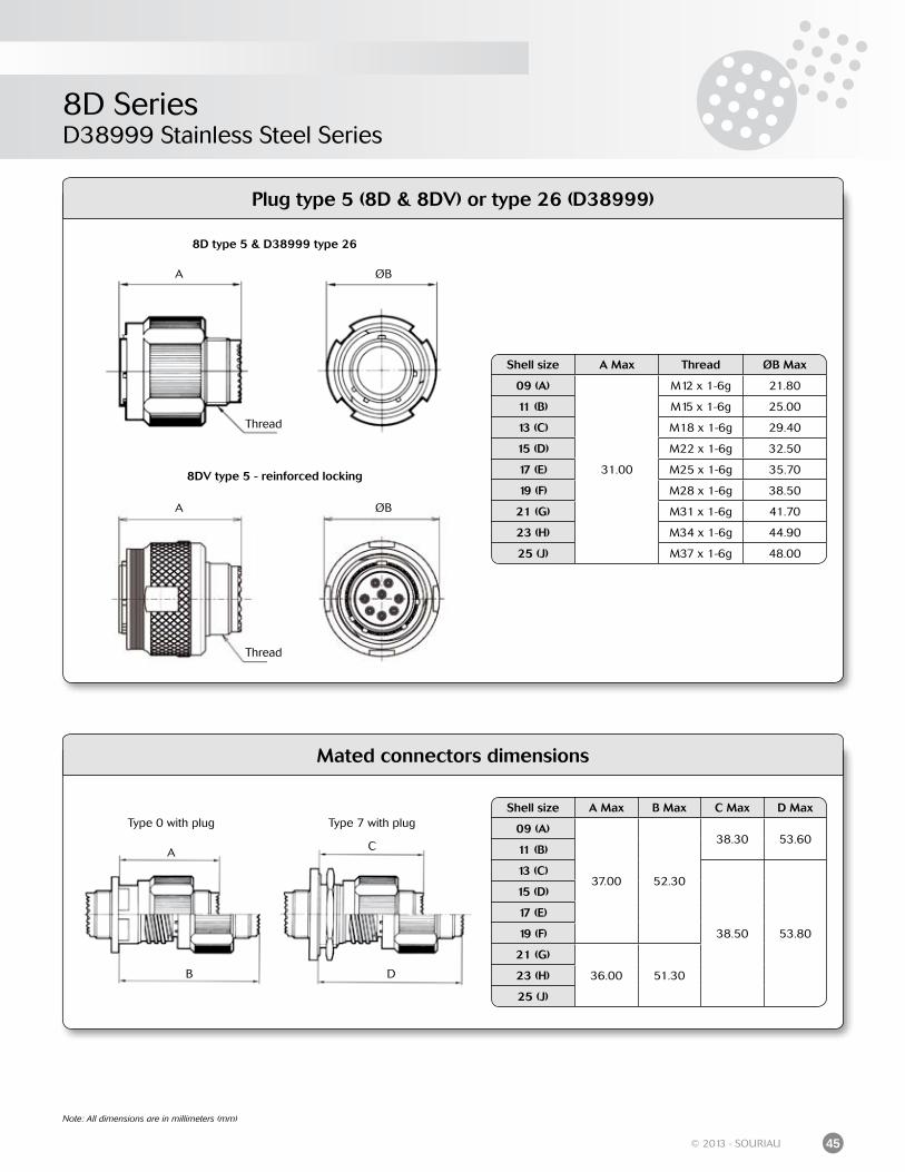
Mated connectors dimensions
Shell size A Max Thread ØB Max
09 (A)
31.00
M12 x 1-6g 21.80
11 (B) M15 x 1-6g 25.00
13 (C) M18 x 1-6g 29.40
15 (D) M22 x 1-6g 32.50
17 (E) M25 x 1-6g 35.70
19 (F) M28 x 1-6g 38.50
21 (G) M31 x 1-6g 41.70
23 (H) M34 x 1-6g 44.90
25 (J) M37 x 1-6g 48.00
Shell size A Max B Max C Max D Max
09 (A)
37.00 52.30
38.30 53.6011 (B)
13 (C)
38.50 53.80
15 (D)
17 (E)
19 (F)
21 (G)
36.00 51.3023 (H)
25 (J)
A ØB
Thread
Type 0 with plug Type 7 with plug
A
B
C
D
Plug type 5 (8D & 8DV) or type 26 (D38999)
A ØB
Thread
8D type 5 & D38999 type 26
8DV type 5 - reinforced locking
8D SeriesD38999 Stainless Steel Series
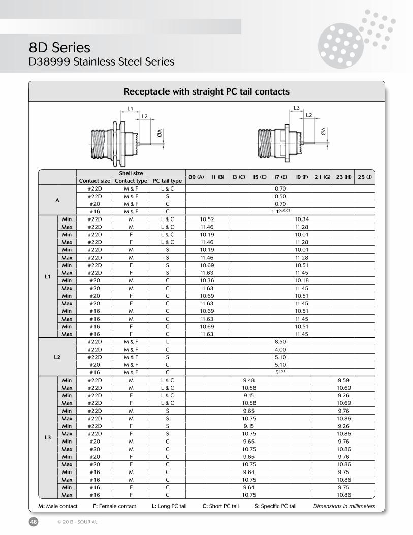
46 © 2013 - SOURIAU
Receptacle with straight PC tail contacts
M: Male contact F: Female contact L: Long PC tail C: Short PC tail S: Specific PC tail Dimensions in millimeters
L1
L2
ØA
L3L2
ØA
Shell size09 (A) 11 (B) 13 (C) 15 (C) 17 (E) 19 (F) 21 (G) 23 (H) 25 (J)
Contact size Contact type PC tail type
A
#22D M & F L & C 0.70#22D M & F S 0.50#20 M & F C 0.70#16 M & F C 1.12±0.03
L1
Min #22D M L & C 10.52 10.34Max #22D M L & C 11.46 11.28Min #22D F L & C 10.19 10.01Max #22D F L & C 11.46 11.28Min #22D M S 10.19 10.01Max #22D M S 11.46 11.28Min #22D F S 10.69 10.51Max #22D F S 11.63 11.45Min #20 M C 10.36 10.18Max #20 M C 11.63 11.45Min #20 F C 10.69 10.51Max #20 F C 11.63 11.45Min #16 M C 10.69 10.51Max #16 M C 11.63 11.45Min #16 F C 10.69 10.51Max #16 F C 11.63 11.45
L2
#22D M & F L 8.50#22D M & F C 4.00#22D M & F S 5.10#20 M & F C 5.10#16 M & F C 5±0.1
L3
Min #22D M L & C 9.48 9.59Max #22D M L & C 10.58 10.69Min #22D F L & C 9.15 9.26Max #22D F L & C 10.58 10.69Min #22D M S 9.65 9.76Max #22D M S 10.75 10.86Min #22D F S 9.15 9.26Max #22D F S 10.75 10.86Min #20 M C 9.65 9.76Max #20 M C 10.75 10.86Min #20 F C 9.65 9.76Max #20 F C 10.75 10.86Min #16 M C 9.64 9.75Max #16 M C 10.75 10.86Min #16 F C 9.64 9.75Max #16 F C 10.75 10.86
8D SeriesD38999 Stainless Steel Series
47© 2013 - SOURIAU
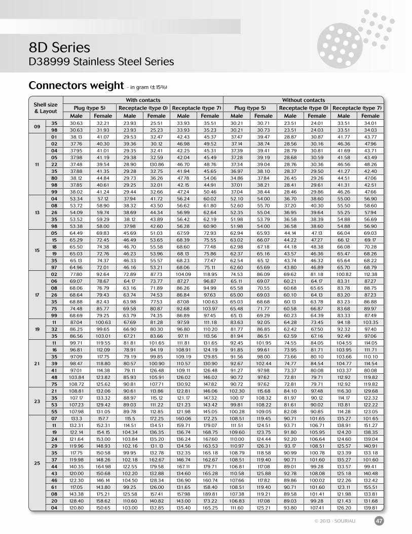
Connectors weight - in gram (±15%)
Shell size& Layout
With contacts Without contactsPlug (type 5) Receptacle (type 0) Receptacle (type 7) Plug (type 5) Receptacle (type 0) Receptacle (type 7)
Male Female Male Female Male Female Male Female Male Female Male Female
0935 30.63 32.21 23.93 25.51 33.93 35.51 30.21 30.71 23.51 24.01 33.51 34.0198 30.63 31.93 23.93 25.23 33.93 35.23 30.21 30.73 23.51 24.03 33.51 34.03
11
01 38.13 41.07 29.53 32.47 42.43 45.37 37.47 39.47 28.87 30.87 41.77 43.7702 37.76 40.30 39.36 30.12 46.98 49.52 37.14 38.74 28.56 30.16 46.36 47.9604 37.95 41.01 29.35 32.41 42.25 45.31 37.39 39.41 28.79 30.81 41.69 43.7105 37.98 41.19 29.38 32.59 42.04 45.49 37.28 39.19 28.68 30.59 41.58 43.4922 37.48 39.54 28.90 130.86 46.70 48.76 37.34 39.04 28.76 30.36 46.56 48.2635 37.88 41.35 29.28 32.75 41.94 45.65 36.97 38.10 28.37 29.50 41.27 42.4080 38.12 44.84 29.73 36.26 47.78 54.06 34.86 37.84 26.45 29.26 44.51 47.0698 37.85 40.61 29.25 32.01 42.15 44.91 37.01 38.21 28.41 29.61 41.31 42.5199 38.02 41.24 29.44 32.66 47.24 50.46 37.04 38.44 28.46 29.86 46.26 47.66
13
04 53.34 57.12 37.94 41.72 56.24 60.02 52.10 54.00 36.70 38.60 55.00 56.9008 53.72 58.90 38.32 43.50 56.62 61.80 52.60 55.70 37.20 40.30 55.50 58.6026 54.09 59.74 38.69 44.34 56.99 62.64 52.35 55.04 36.95 39.64 55.25 57.9435 53.52 59.29 38.12 43.89 56.42 62.19 51.98 53.79 36.58 38.39 54.88 56.6998 53.38 58.00 37.98 42.60 56.28 60.90 51.98 54.00 36.58 38.60 54.88 56.90
15
05 64.49 69.83 45.69 51.03 67.59 72.93 62.94 65.93 44.14 47.13 66.04 69.0315 65.29 72.45 46.49 53.65 68.39 75.55 63.02 66.07 44.22 47.27 66.12 69.1718 65.50 74.38 46.70 55.58 68.60 77.48 62.98 67.18 44.18 48.38 66.08 70.2819 65.03 72.76 46.23 53.96 68.13 75.86 62.37 65.16 43.57 46.36 65.47 68.2635 65.13 74.37 46.33 55.57 68.23 77.47 62.54 65.12 43.74 46.32 65.64 68.2297 64.96 72.01 46.16 53.21 68.06 75.11 62.60 65.69 43.80 46.89 65.70 68.79
17
02 77.80 92.64 72.89 87.73 104.09 118.95 74.53 86.09 69.62 81.18 100.82 112.3806 69.07 78.67 64.17 73.77 87.27 96.87 65.11 69.07 60.21 64.17 83.31 87.2708 68.06 76.79 63.16 71.89 86.26 94.99 65.58 70.55 60.68 65.65 83.78 88.7526 68.64 79.43 63.74 74.53 86.84 97.63 65.00 69.03 60.10 64.13 83.20 87.2335 68.88 82.43 63.98 77.53 87.08 100.63 65.03 68.68 60.13 63.78 83.23 86.8875 74.48 85.77 69.58 80.87 92.68 103.97 65.48 71.77 60.58 66.87 83.68 89.9799 68.69 79.25 63.79 74.35 86.89 97.45 65.13 69.29 60.23 64.39 83.33 87.49
1911 87.04 100.63 67.69 81.28 97.59 111.18 83.63 92.05 64.28 73.45 94.18 103.3532 86.25 99.65 66.90 80.30 96.80 110.20 81.77 86.85 62.42 67.50 92.32 97.4035 86.56 103.01 67.21 83.66 97.11 113.56 81.94 86.51 62.59 67.16 92.49 97.06
21
11 99.71 119.55 81.81 101.65 111.81 131.65 92.45 101.95 74.55 84.05 104.55 114.0516 96.81 112.09 78.91 94.19 108.91 124.19 91.85 99.61 73.95 81.71 103.95 111.7135 97.09 117.75 79.19 99.85 109.19 129.85 91.56 98.00 73.66 80.10 103.66 110.1039 98.47 118.80 80.57 100.90 110.57 130.90 92.67 102.44 74.77 84.54 104.77 114.5441 97.01 114.38 79.11 126.48 109.11 126.48 91.27 97.98 73.37 80.08 103.37 80.0848 103.84 123.82 85.93 105.91 126.02 146.02 90.72 97.62 72.81 79.71 112.92 119.8275 108.72 125.62 90.81 107.71 130.92 147.82 90.72 97.62 72.81 79.71 112.92 119.82
23
21 108.81 132.06 90.61 113.86 122.81 146.06 102.30 115.68 84.10 97.48 116.30 129.6835 107.17 133.32 88.97 115.12 121.17 147.32 100.17 108.32 81.97 90.12 114.17 122.3253 107.23 129.42 89.03 111.22 121.23 143.42 99.81 108.22 81.61 90.02 113.81 122.2255 107.98 131.05 89.78 112.85 121.98 145.05 100.28 109.05 82.08 90.85 114.28 123.05
25
07 133.3 157.7 115.5 172.25 160.06 172.25 108.51 119.45 90.71 101.65 135.27 101.6511 132.31 152.31 114.51 134.51 159.71 179.07 111.51 124.51 93.71 106.71 138.91 151.2719 122.14 154.15 104.34 136.35 136.74 168.75 109.60 123.75 91.80 105.95 124.20 138.3524 121.64 153.00 103.84 135.20 136.24 167.60 110.00 124.44 92.20 106.64 124.60 139.0429 119.96 148.93 102.16 131.13 134.56 163.53 110.97 126.31 93.17 108.51 125.57 140.9135 117.75 150.58 99.95 132.78 132.35 165.18 108.79 118.58 90.99 100.78 123.39 133.1837 119.98 148.26 102.18 162.67 146.74 162.67 108.51 119.40 90.71 101.60 135.27 101.6044 140.35 164.98 122.55 179.58 167.11 179.71 106.81 117.08 89.01 99.28 133.57 99.4143 120.00 150.68 102.20 132.88 134.60 165.28 110.58 125.88 92.78 108.08 125.18 140.4846 122.30 146.14 104.50 128.34 136.90 160.74 107.66 117.82 89.86 100.02 122.26 132.4261 117.05 143.80 99.25 126.00 131.65 158.40 108.51 119.40 90.71 101.60 123.11 155.5108 143.38 175.21 125.58 157.41 157.98 189.81 107.38 119.21 89.58 101.41 121.98 133.8120 128.40 158.62 110.60 140.82 143.00 173.22 106.83 117.08 89.03 99.28 121.43 131.6804 120.80 150.65 103.00 132.85 135.40 165.25 111.60 125.21 93.80 107.41 126.20 139.81
8D SeriesD38999 Titanium Series
48 © 2013 - SOURIAU
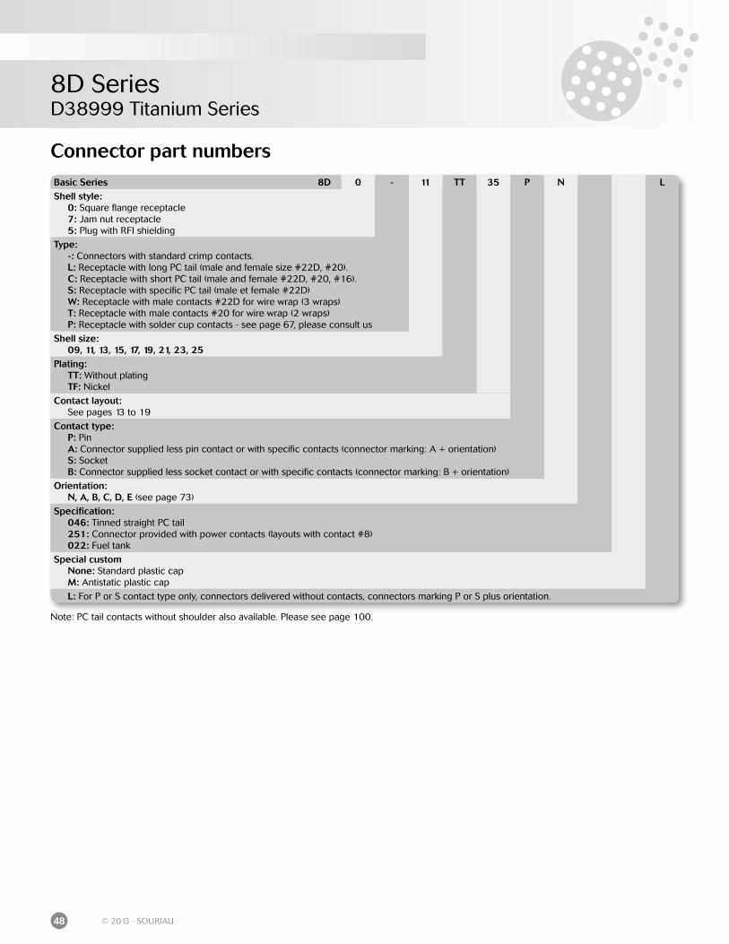
Connector part numbers
Basic Series 8D 0 - 11 TT 35 P N LShell style: 0: Square flange receptacle 7: Jam nut receptacle 5: Plug with RFI shielding
Type: -: Connectors with standard crimp contacts. L: Receptacle with long PC tail (male and female size #22D, #20). C: Receptacle with short PC tail (male and female #22D, #20, #16). S: Receptacle with specific PC tail (male et female #22D) W: Receptacle with male contacts #22D for wire wrap (3 wraps) T: Receptacle with male contacts #20 for wire wrap (2 wraps) P: Receptacle with solder cup contacts - see page 67, please consult us
Shell size: 09, 11, 13, 15, 17, 19, 21, 23, 25Plating: TT: Without plating TF: Nickel
Contact layout: See pages 13 to 19
Contact type: P: Pin A: Connector supplied less pin contact or with specific contacts (connector marking: A + orientation) S: Socket B: Connector supplied less socket contact or with specific contacts (connector marking: B + orientation)
Orientation: N, A, B, C, D, E (see page 73)
Specification: 046: Tinned straight PC tail 251: Connector provided with power contacts (layouts with contact #8) 022: Fuel tank
Special custom None: Standard plastic cap M: Antistatic plastic cap
L: For P or S contact type only, connectors delivered without contacts, connectors marking P or S plus orientation.
Note: PC tail contacts without shoulder also available. Please see page 100.
8D SeriesD38999 Titanium Series
49© 2013 - SOURIAU
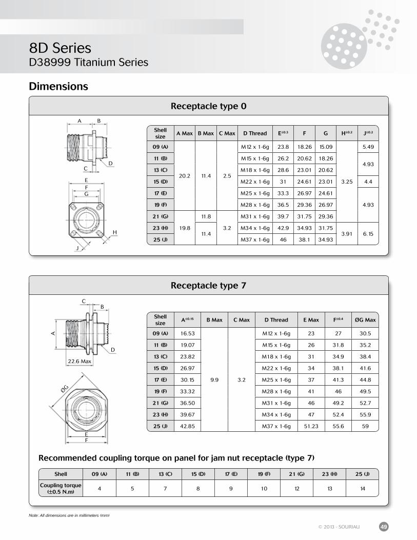
Dimensions
Receptacle type 0
Receptacle type 7
Recommended coupling torque on panel for jam nut receptacle (type 7)
Note: All dimensions are in millimeters (mm)
Shell 09 (A) 11 (B) 13 (C) 15 (D) 17 (E) 19 (F) 21 (G) 23 (H) 25 (J)
Coupling torque(±0.5 N.m)
4 5 7 8 9 10 12 13 14
Shell size
A Max B Max C Max D Thread E±0.3 F G H±0.2 J±0.2
09 (A)
20.2 11.4 2.5
M12 x 1-6g 23.8 18.26 15.09
3.25
5.49
11 (B) M15 x 1-6g 26.2 20.62 18.264.93
13 (C) M18 x 1-6g 28.6 23.01 20.62
15 (D) M22 x 1-6g 31 24.61 23.01 4.4
17 (E) M25 x 1-6g 33.3 26.97 24.61
4.9319 (F) M28 x 1-6g 36.5 29.36 26.97
21 (G)
19.8
11.8
3.2
M31 x 1-6g 39.7 31.75 29.36
23 (H)11.4
M34 x 1-6g 42.9 34.93 31.753.91 6.15
25 (J) M37 x 1-6g 46 38.1 34.93
A B
CD
EFG
H
J
A
BC
D
EF
ØG
22.6 Max
Shell size
A±0.15 B Max C Max D Thread E Max F±0.4 ØG Max
09 (A) 16.53
9.9 3.2
M12 x 1-6g 23 27 30.5
11 (B) 19.07 M15 x 1-6g 26 31.8 35.2
13 (C) 23.82 M18 x 1-6g 31 34.9 38.4
15 (D) 26.97 M22 x 1-6g 34 38.1 41.6
17 (E) 30.15 M25 x 1-6g 37 41.3 44.8
19 (F) 33.32 M28 x 1-6g 41 46 49.5
21 (G) 36.50 M31 x 1-6g 46 49.2 52.7
23 (H) 39.67 M34 x 1-6g 47 52.4 55.9
25 (J) 42.85 M37 x 1-6g 51.23 55.6 59
8D SeriesD38999 Titanium Series
50 © 2013 - SOURIAU
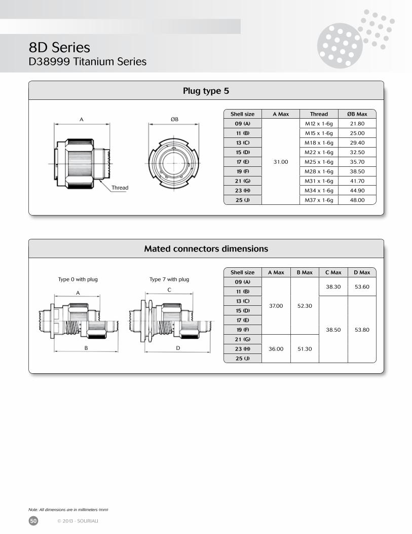
Note: All dimensions are in millimeters (mm)
Mated connectors dimensions
Shell size A Max Thread ØB Max
09 (A)
31.00
M12 x 1-6g 21.80
11 (B) M15 x 1-6g 25.00
13 (C) M18 x 1-6g 29.40
15 (D) M22 x 1-6g 32.50
17 (E) M25 x 1-6g 35.70
19 (F) M28 x 1-6g 38.50
21 (G) M31 x 1-6g 41.70
23 (H) M34 x 1-6g 44.90
25 (J) M37 x 1-6g 48.00
Shell size A Max B Max C Max D Max
09 (A)
37.00 52.30
38.30 53.6011 (B)
13 (C)
38.50 53.80
15 (D)
17 (E)
19 (F)
21 (G)
36.00 51.3023 (H)
25 (J)
A ØB
Thread
Type 0 with plug Type 7 with plug
A
B
C
D
Plug type 5
8D SeriesD38999 Titanium Series
51© 2013 - SOURIAU
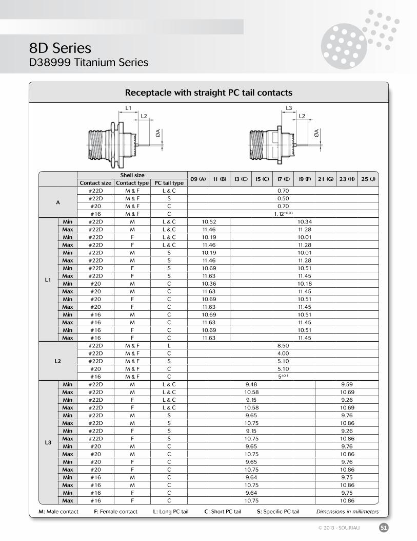
Receptacle with straight PC tail contacts
M: Male contact F: Female contact L: Long PC tail C: Short PC tail S: Specific PC tail Dimensions in millimeters
L1
L2
ØA
L3
L2
ØA
Shell size09 (A) 11 (B) 13 (C) 15 (C) 17 (E) 19 (F) 21 (G) 23 (H) 25 (J)
Contact size Contact type PC tail type
A
#22D M & F L & C 0.70#22D M & F S 0.50#20 M & F C 0.70#16 M & F C 1.12±0.03
L1
Min #22D M L & C 10.52 10.34Max #22D M L & C 11.46 11.28Min #22D F L & C 10.19 10.01Max #22D F L & C 11.46 11.28Min #22D M S 10.19 10.01Max #22D M S 11.46 11.28Min #22D F S 10.69 10.51Max #22D F S 11.63 11.45Min #20 M C 10.36 10.18Max #20 M C 11.63 11.45Min #20 F C 10.69 10.51Max #20 F C 11.63 11.45Min #16 M C 10.69 10.51Max #16 M C 11.63 11.45Min #16 F C 10.69 10.51Max #16 F C 11.63 11.45
L2
#22D M & F L 8.50#22D M & F C 4.00#22D M & F S 5.10#20 M & F C 5.10#16 M & F C 5±0.1
L3
Min #22D M L & C 9.48 9.59Max #22D M L & C 10.58 10.69Min #22D F L & C 9.15 9.26Max #22D F L & C 10.58 10.69Min #22D M S 9.65 9.76Max #22D M S 10.75 10.86Min #22D F S 9.15 9.26Max #22D F S 10.75 10.86Min #20 M C 9.65 9.76Max #20 M C 10.75 10.86Min #20 F C 9.65 9.76Max #20 F C 10.75 10.86Min #16 M C 9.64 9.75Max #16 M C 10.75 10.86Min #16 F C 9.64 9.75Max #16 F C 10.75 10.86
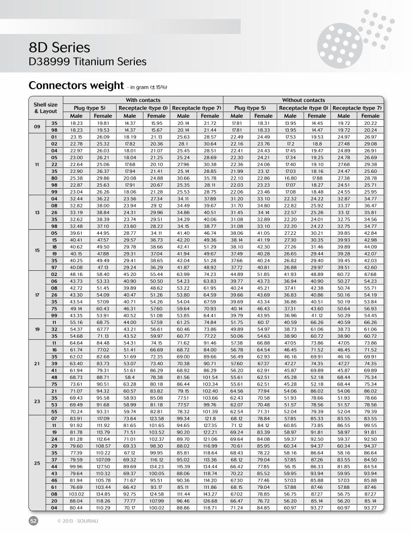
8D SeriesD38999 Titanium Series
52 © 2013 - SOURIAU
Connectors weight - in gram (±15%)
Shell size& Layout
With contacts Without contactsPlug (type 5) Receptacle (type 0) Receptacle (type 7) Plug (type 5) Receptacle (type 0) Receptacle (type 7)
Male Female Male Female Male Female Male Female Male Female Male Female
0935 18.23 19.81 14.37 15.95 20.14 21.72 17.81 18.31 13.95 14.45 19.72 20.2298 18.23 19.53 14.37 15.67 20.14 21.44 17.81 18.33 13.95 14.47 19.72 20.24
11
01 23.15 26.09 18.19 21.13 25.63 28.57 22.49 24.49 17.53 19.53 24.97 26.9702 22.78 25.32 17.82 20.36 28.1 30.64 22.16 23.76 17.2 18.8 27.48 29.0804 22.97 26.03 18.01 21.07 25.45 28.51 22.41 24.43 17.45 19.47 24.89 26.9105 23.00 26.21 18.04 21.25 25.24 28.69 22.30 24.21 17.34 19.25 24.78 26.6922 22.64 25.06 17.68 20.10 27.96 30.38 22.36 24.06 17.40 19.10 27.68 29.3835 22.90 26.37 17.94 21.41 25.14 28.85 21.99 23.12 17.03 18.16 24.47 25.6080 25.38 29.86 20.08 24.88 30.66 35.78 22.10 22.86 16.80 17.88 27.38 28.7898 22.87 25.63 17.91 20.67 25.35 28.11 22.03 23.23 17.07 18.27 24.51 25.7199 23.04 26.26 18.06 21.28 25.53 28.75 22.06 23.46 17.08 18.48 24.55 25.95
13
04 32.44 36.22 23.56 27.34 34.11 37.89 31.20 33.10 22.32 24.22 32.87 34.7708 32.82 38.00 23.94 29.12 34.49 39.67 31.70 34.80 22.82 25.92 33.37 36.4726 33.19 38.84 24.31 29.96 34.86 40.51 31.45 34.14 22.57 25.26 33.12 35.8135 32.62 38.39 23.74 29.51 34.29 40.06 31.08 32.89 22.20 24.01 32.75 34.5698 32.48 37.10 23.60 28.22 34.15 38.77 31.08 33.10 22.20 24.22 32.75 34.77
15
05 39.61 44.95 28.77 34.11 41.40 46.74 38.06 41.05 27.22 30.21 39.85 42.8415 40.41 47.57 29.57 36.73 42.20 49.36 38.14 41.19 27.30 30.35 39.93 42.9818 40.62 49.50 29.78 38.66 42.41 51.29 38.10 42.30 27.26 31.46 39.89 44.0919 40.15 47.88 29.31 37.04 41.94 49.67 37.49 40.28 26.65 29.44 39.28 42.0735 40.25 49.49 29.41 38.65 42.04 51.28 37.66 40.24 26.82 29.40 39.45 42.0397 40.08 47.13 29.24 36.29 41.87 48.92 37.72 40.81 26.88 29.97 39.51 42.60
17
02 48.16 58.40 45.20 55.44 63.99 74.23 44.89 51.85 41.93 48.89 60.72 67.6806 43.73 53.33 40.90 50.50 54.23 63.83 39.77 43.73 36.94 40.90 50.27 54.2308 42.72 51.45 39.89 48.62 53.22 61.95 40.24 45.21 37.41 42.38 50.74 55.7126 43.30 54.09 40.47 51.26 53.80 64.59 39.66 43.69 36.83 40.86 50.16 54.1935 43.54 57.09 40.71 54.26 54.04 67.59 39.69 43.34 36.86 40.51 50.19 53.8475 49.14 60.43 46.31 57.60 59.64 70.93 40.14 46.43 37.31 43.60 50.64 56.9399 43.35 53.91 40.52 51.08 53.85 64.41 39.79 43.95 36.96 41.12 50.29 54.45
1911 55.16 68.75 44.00 57.59 61.25 74.84 51.75 60.17 40.59 66.26 40.59 66.2632 54.37 67.77 43.21 56.61 60.46 73.86 49.89 54.97 38.73 61.06 38.73 61.0635 54.68 71.13 43.52 59.97 60.77 77.22 50.06 54.63 38.90 60.72 38.90 60.72
21
11 64.64 84.48 54.31 74.15 71.62 91.46 57.38 66.88 47.05 73.86 47.05 73.8616 61.74 77.02 51.41 66.69 68.72 84.00 56.78 64.54 46.45 71.52 46.45 71.5235 62.02 82.68 51.69 72.35 69.00 89.66 56.49 62.93 46.16 69.91 46.16 69.9139 63.40 83.73 53.07 73.40 70.38 90.71 57.60 67.37 47.27 74.35 47.27 74.3541 61.94 79.31 51.61 86.29 68.92 86.29 56.20 62.91 45.87 69.89 45.87 69.8948 68.73 88.71 58.4 78.38 81.56 101.54 55.61 62.51 45.28 52.18 68.44 75.3475 73.61 90.51 63.28 80.18 86.44 103.34 55.61 62.51 45.28 52.18 68.44 75.34
23
21 71.07 94.32 60.57 83.82 79.15 102.40 64.56 77.94 54.06 86.02 54.06 86.0235 69.43 95.58 58.93 85.08 77.51 103.66 62.43 70.58 51.93 78.66 51.93 78.6653 69.49 91.68 58.99 81.18 77.57 99.76 62.07 70.48 51.57 78.56 51.57 78.5655 70.24 93.31 59.74 82.81 78.32 101.39 62.54 71.31 52.04 79.39 52.04 79.39
25
07 83.91 117.09 73.64 123.58 99.34 121.8 68.12 78.84 57.85 85.33 83.55 83.5511 91.92 111.92 81.65 101.65 94.65 127.35 71.12 84.12 60.85 73.85 86.55 99.5519 81.78 113.79 71.51 103.52 90.20 122.21 69.24 83.39 58.97 91.81 58.97 91.8124 81.28 112.64 71.01 102.37 89.70 121.06 69.64 84.08 59.37 92.50 59.37 92.5029 79.60 108.57 69.33 98.30 88.02 116.99 70.61 85.95 60.34 94.37 60.34 94.3735 77.39 110.22 67.12 99.95 85.81 118.64 68.43 78.22 58.16 86.64 58.16 86.6437 79.59 107.09 69.32 116.12 95.02 113.36 68.12 79.04 57.85 87.26 83.55 84.5044 99.96 127.50 89.69 134.23 115.39 134.44 66.42 77.85 56.15 86.33 81.85 84.5443 79.64 110.32 69.37 100.05 88.06 118.74 70.22 85.52 59.95 93.94 59.95 93.9446 81.94 105.78 71.67 95.51 90.36 114.20 67.30 77.46 57.03 85.88 57.03 85.8861 76.69 103.44 66.42 93.17 85.11 111.86 68.15 79.04 57.88 87.46 57.88 87.4608 103.02 134.85 92.75 124.58 111.44 143.27 67.02 78.85 56.75 87.27 56.75 87.2720 88.04 118.26 77.77 107.99 96.46 126.68 66.47 76.72 56.20 85.14 56.20 85.1404 80.44 110.29 70.17 100.02 88.86 118.71 71.24 84.85 60.97 93.27 60.97 93.27
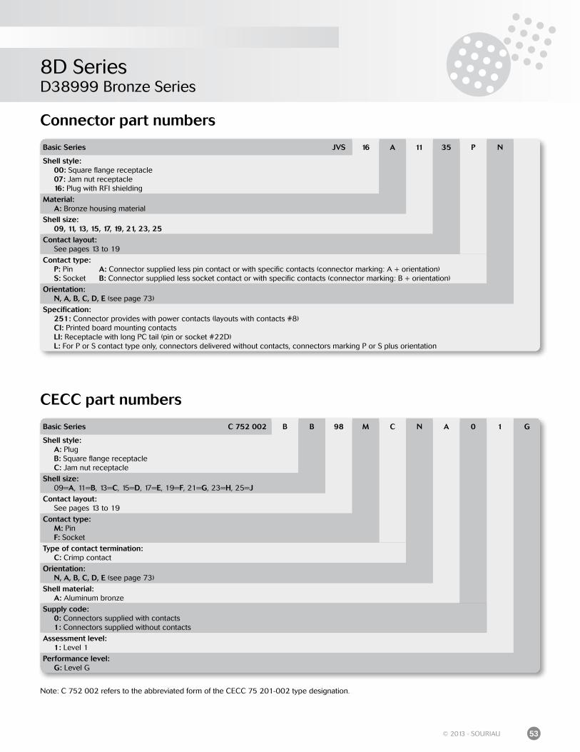
8D SeriesD38999 Bronze Series
53© 2013 - SOURIAU
Connector part numbers
CECC part numbers
Basic Series JVS 16 A 11 35 P N
Shell style: 00: Square flange receptacle 07: Jam nut receptacle 16: Plug with RFI shielding
Material: A: Bronze housing material
Shell size: 09, 11, 13, 15, 17, 19, 21, 23, 25Contact layout: See pages 13 to 19
Contact type: P: Pin A: Connector supplied less pin contact or with specific contacts (connector marking: A + orientation) S: Socket B: Connector supplied less socket contact or with specific contacts (connector marking: B + orientation)
Orientation: N, A, B, C, D, E (see page 73)
Specification: 251: Connector provides with power contacts (layouts with contacts #8) CI: Printed board mounting contacts LI: Receptacle with long PC tail (pin or socket #22D) L: For P or S contact type only, connectors delivered without contacts, connectors marking P or S plus orientation
Basic Series C 752 002 B B 98 M C N A 0 1 G
Shell style: A: Plug B: Square flange receptacle C: Jam nut receptacle
Shell size: 09=A, 11=B, 13=C, 15=D, 17=E, 19=F, 21=G, 23=H, 25=JContact layout: See pages 13 to 19
Contact type: M: Pin F: Socket
Type of contact termination: C: Crimp contact
Orientation: N, A, B, C, D, E (see page 73)
Shell material: A: Aluminum bronze
Supply code: 0: Connectors supplied with contacts 1: Connectors supplied without contacts
Assessment level: 1: Level 1
Performance level: G: Level G
Note: C 752 002 refers to the abbreviated form of the CECC 75 201-002 type designation.
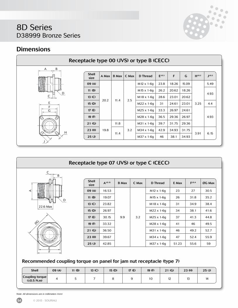
8D SeriesD38999 Bronze Series
54 © 2013 - SOURIAU
Dimensions
Recommended coupling torque on panel for jam nut receptacle (type 7)
Note: All dimensions are in millimeters (mm)
Shell 09 (A) 11 (B) 13 (C) 15 (D) 17 (E) 19 (F) 21 (G) 23 (H) 25 (J)
Coupling torque(±0.5 N.m)
4 5 7 8 9 10 12 13 14
Shell size
A Max B Max C Max D Thread E±0.3 F G H±0.2 J±0.2
09 (A)
20.2 11.4 2.5
M12 x 1-6g 23.8 18.26 15.09
3.25
5.49
11 (B) M15 x 1-6g 26.2 20.62 18.264.93
13 (C) M18 x 1-6g 28.6 23.01 20.62
15 (D) M22 x 1-6g 31 24.61 23.01 4.4
17 (E) M25 x 1-6g 33.3 26.97 24.61
4.9319 (F) M28 x 1-6g 36.5 29.36 26.97
21 (G)
19.8
11.8
3.2
M31 x 1-6g 39.7 31.75 29.36
23 (H)11.4
M34 x 1-6g 42.9 34.93 31.753.91 6.15
25 (J) M37 x 1-6g 46 38.1 34.93
Receptacle type 00 (JVS) or type B (CECC)
Receptacle type 07 (JVS) or type C (CECC)
A B
CD
EFG
H
J
A
BC
D
EF
ØG
22.6 Max
Shell size
A±0.15 B Max C Max D Thread E Max F±0.4 ØG Max
09 (A) 16.53
9.9 3.2
M12 x 1-6g 23 27 30.5
11 (B) 19.07 M15 x 1-6g 26 31.8 35.2
13 (C) 23.82 M18 x 1-6g 31 34.9 38.4
15 (D) 26.97 M22 x 1-6g 34 38.1 41.6
17 (E) 30.15 M25 x 1-6g 37 41.3 44.8
19 (F) 33.32 M28 x 1-6g 41 46 49.5
21 (G) 36.50 M31 x 1-6g 46 49.2 52.7
23 (H) 39.67 M34 x 1-6g 47 52.4 55.9
25 (J) 42.85 M37 x 1-6g 51.23 55.6 59
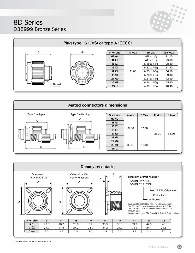
8D SeriesD38999 Bronze Series
55© 2013 - SOURIAU
Note: All dimensions are in millimeters (mm)
Mated connectors dimensions
Shell size A Max Thread ØB Max09 (A)
31.00
M12 x 1-6g 21.10
11 (B) M15 x 1-6g 23.80
13 (C) M18 x 1-6g 28.20
15 (D) M22 x 1-6g 31.40
17 (E) M25 x 1-6g 36.50
19 (F) M28 x 1-6g 39.30
21 (G) M31 x 1-6g 42.50
23 (H) M34 x 1-6g 45.30
25 (J) M37 x 1-6g 48.40
Shell size A Max B Max C Max D Max09 (A)
37.00 52.30
38.30 53.60
11 (B)13 (C)15 (D)17 (E)19 (F)21 (G)
36.00 51.3023 (H)25 (J)
A ØB
Thread
Type 0 with plug Type 7 with plug
A
B
C
D
Plug type 16 (JVS) or type A (CECC)
A
A
Orientation: DU(= all orientations)
Dummy receptacle
B
CA
A
Orientation:N, A, B, C, D, E
Shell size 9 11 13 15 17 19 21 23 25A+0.3 23.8 26.2 28.6 31 33.3 36.5 39.7 42.9 46B maxi 24.2 24.2 24.2 24.2 24.2 24.2 24.1 24.1 24.1C maxi 2.5 2.5 2.5 2.5 2.5 2.5 3.2 3.2 3.2
-0.3
Examples of Part Number:
. JVS BN 02 A 17 N
. JVS BN 02 A 17 DU
Equivalent to CECC blind hole. For information only:CECC75201002AxA00A (x = shell size A, B, C, D, .. )CECC75201002EA00A (blind hole) = JVSBN02A17DU (through hole)(no correspondance CECC with N, A, B, C, D, E orientations)
N, DU: Orientation
A: Bronze
17: Shell size
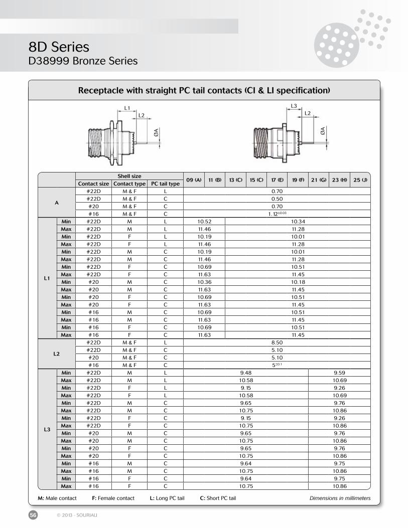
8D SeriesD38999 Bronze Series
56 © 2013 - SOURIAU
Receptacle with straight PC tail contacts (CI & LI specification)
M: Male contact F: Female contact L: Long PC tail C: Short PC tail Dimensions in millimeters
Shell size09 (A) 11 (B) 13 (C) 15 (C) 17 (E) 19 (F) 21 (G) 23 (H) 25 (J)
Contact size Contact type PC tail type
A
#22D M & F L 0.70#22D M & F C 0.50#20 M & F C 0.70#16 M & F C 1.12±0.03
L1
Min #22D M L 10.52 10.34Max #22D M L 11.46 11.28Min #22D F L 10.19 10.01Max #22D F L 11.46 11.28Min #22D M C 10.19 10.01Max #22D M C 11.46 11.28Min #22D F C 10.69 10.51Max #22D F C 11.63 11.45Min #20 M C 10.36 10.18Max #20 M C 11.63 11.45Min #20 F C 10.69 10.51Max #20 F C 11.63 11.45Min #16 M C 10.69 10.51Max #16 M C 11.63 11.45Min #16 F C 10.69 10.51Max #16 F C 11.63 11.45
L2
#22D M & F L 8.50#22D M & F C 5.10#20 M & F C 5.10#16 M & F C 5±0.1
L3
Min #22D M L 9.48 9.59Max #22D M L 10.58 10.69Min #22D F L 9.15 9.26Max #22D F L 10.58 10.69Min #22D M C 9.65 9.76Max #22D M C 10.75 10.86Min #22D F C 9.15 9.26Max #22D F C 10.75 10.86Min #20 M C 9.65 9.76Max #20 M C 10.75 10.86Min #20 F C 9.65 9.76Max #20 F C 10.75 10.86Min #16 M C 9.64 9.75Max #16 M C 10.75 10.86Min #16 F C 9.64 9.75Max #16 F C 10.75 10.86
L1L2
ØA
L3L2
ØA
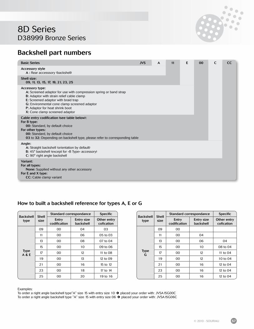
8D SeriesD38999 Bronze Series
57© 2013 - SOURIAU
Backshell part numbersBasic Series JVS A 11 E 00 C CC
Accessory style A : Rear accesssory (backshell)
Shell size: 09, 11, 13, 15, 17, 19, 21, 23, 25
Accessory type: A: Screened adaptor for use with compression spring or band strap B: Adaptor with strain relief cable clamp E: Screened adaptor with braid trap G: Environmental cone clamp screened adaptor P: Adaptor for heat shrink boot X: Cone clamp screened adaptor
Cable entry codification (see table below):For B type: 00: Standard, by default choiceFor other types: 00: Standard, by default choice 03 to 32: Depending on backshell type, please refer to corresponding table
Angle: A: Straight backshell (orientation by default) B: 45° backshell (except for «B Type» accessory) C: 90° right angle backshell
Variant:For all types: None: Supplied without any other accessoryFor E and X type: CC: Cable clamp variant
How to built a backshell reference for types A, E or G
Examples:To order a right angle backshell type"A" size 15 with entry size 10 placed your order with: JVSA15G00C To order a right angle backshell type "A" size 15 with entry size 06 placed your order with: JVSA15G06C
Backshell type
Shell size
Standard correspondance Specific
Entrycodification
Entry size backshell
Other entry cofication
TypeA & E
09 00 04 03
11 00 06 05 to 03
13 00 08 07 to 04
15 00 10 09 to 06
17 00 12 11 to 08
19 00 13 12 to 09
21 00 16 15 to 12
23 00 18 17 to 14
25 00 20 19 to 16
Backshell type
Shell size
Standard correspondance Specific
Entrycodification
Entry size backshell
Other entry cofication
TypeG
09 00
11 00 04
13 00 06 04
15 00 10 08 to 04
17 00 12 11 to 04
19 00 12 10 to 04
21 00 16 12 to 04
23 00 16 12 to 04
25 00 16 12 to 04
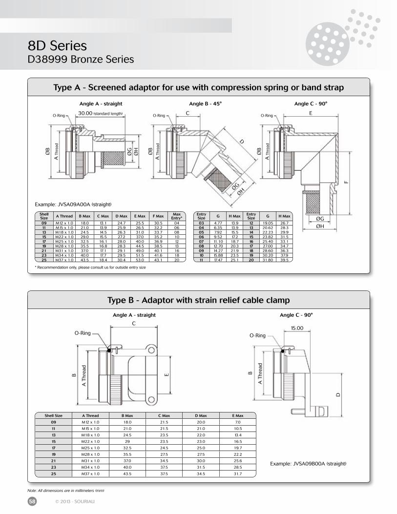
8D SeriesD38999 Bronze Series
58 © 2013 - SOURIAU
Angle B - 45°Angle A - straight Angle C - 90°
O-Ring
A T
hrea
d
30.00 (standard length)
A T
hrea
d
O-Ring O-Ring
A T
hrea
d
C E
D
ØGØH
ØB
ØB
ØB
ØG
ØH
ØG
ØH
F
* Recommendation only, please consult us for outside entry size
ShellSize A Thread B Max C Max D Max E Max F Max Max
Entry*09 M12 x 1.0 18.0 13.1 24.7 25.5 30.5 0411 M15 x 1.0 21.0 13.9 25.9 26.5 32.2 0613 M18 x 1.0 24.5 14.5 26.3 31.0 33.7 0815 M22 x 1.0 29.0 15.5 27.2 37.0 35.2 1017 M25 x 1.0 32.5 16.1 28.0 40.0 36.9 1219 M28 x 1.0 35.5 16.8 28.3 44.5 38.5 1321 M31 x 1.0 37.0 17.1 29.1 49.0 40.1 1623 M34 x 1.0 40.0 17.7 29.5 51.5 41.6 1825 M37 x 1.0 43.5 18.4 30.4 53.0 43.1 20
EntrySize G H Max Entry
Size G H Max
03 4.77 13.9 12 19.05 26.704 6.35 13.9 13 20.62 28.305 7.92 15.5 14 22.23 29.906 9.52 17.2 15 23.82 31.507 11.10 18.7 16 25.40 33.108 12.70 20.3 17 27.00 34.709 14.27 21.9 18 28.60 36.310 15.88 23.5 19 30.20 37.911 17.47 25.1 20 31.80 39.5
Type A - Screened adaptor for use with compression spring or band strap
Type B - Adaptor with strain relief cable clamp
Example: JVSA09A00A (straight)
Example: JVSA09B00A (straight)
Note: All dimensions are in millimeters (mm)
Angle A - straight
A T
hrea
d
C
O-Ring
B E
Angle C - 90°
A T
hrea
d
15.00O-Ring
B
D
Shell Size A Thread B Max C Max D Max E Max
09 M12 x 1.0 18.0 21.5 20.0 7.0
11 M15 x 1.0 21.0 21.5 21.0 10.5
13 M18 x 1.0 24.5 23.5 22.0 13.4
15 M22 x 1.0 29 23.5 23.0 16.5
17 M25 x 1.0 32.5 24.5 25.0 19.7
19 M28 x 1.0 35.5 27.5 27.5 22.2
21 M31 x 1.0 37.0 34.5 30.0 25.6
23 M34 x 1.0 40.0 37.5 31.5 28.5
25 M37 x 1.0 43.5 37.5 34.5 31.7
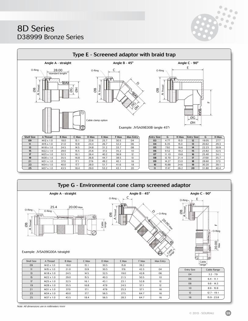
8D SeriesD38999 Bronze Series
59© 2013 - SOURIAU
25.4O-Ring
A T
hrea
d
20.00 Max
A T
hrea
d
O-RingO-Ring
A T
hrea
d
C E
D
ØB
ØB
ØB
Cab
le
rang
e
F
Angle B - 45°Angle A - straight Angle C - 90°
O-RingO-Ring
Cable
rang
e
20.00 M
axO-Ring
20
.00
M
ax
Cable range
O-Ring
A T
hrea
d
28.00(standard length)
A T
hrea
d
O-Ring O-Ring
A T
hrea
d
CE
D
ØG
ØH
ØB
ØB
ØB
ØG
ØH
ØG
ØH
F
Cable clamp option
Angle B - 45°Angle A - straight Angle C - 90°
Type E - Screened adaptor with braid trap
Shell Size A Thread B Max C Max D Max E Max F Max Max Entry09 M12 x 1.0 18.0 13.1 23.6 25.7 30.5 0411 M15 x 1.0 21.0 13.9 24.4 26.7 32.2 0613 M18 x 1.0 24.5 14.5 24.8 31.2 33.7 0815 M22 x 1.0 29.0 15.5 25.6 37.2 35.2 1017 M25 x 1.0 32.5 16.1 26.4 40.2 36.9 1219 M28 x 1.0 35.5 16.8 26.8 44.7 38.5 1321 M31 x 1.0 37.0 17.1 27.6 49.2 40.1 1623 M34 x 1.0 40.0 17.7 28.0 51.7 41.6 1825 M37 x 1.0 43.5 18.4 29.0 53.2 43.1 20
Entry Size G H Max Entry Size G H Max03 4.77 15.0 12 19.05 27.704 6.35 15.0 13 20.62 29.305 7.92 16.6 14 22.23 30.906 9.52 18.2 15 23.82 32.507 11.10 19.8 16 25.40 34.108 12.70 21.4 17 27.00 35.709 14.27 23.0 18 28.60 37.310 15.88 24.6 19 30.20 39.111 17.47 26.2 20 31.80 40.4
Type G - Environmental cone clamp screened adaptor
Entry Size Cable Range
04 3.2 - 7.9
06 6.4 - 11.1
08 9.8 - 14.3
10 8.9 - 15.9
12 12.7 - 19.1
16 15.9 - 23.8
Example: JVSA09E00B (angle 45°)
Example: JVSA09G00A (straight)
Note: All dimensions are in millimeters (mm)
Shell Size A Thread B Max C Max D Max E Max F Max Max Entry
09 M12 x 1.0 18.0 13.1 30.5 15.8 39.2 -
11 M15 x 1.0 21.0 13.9 30.5 17.6 42.3 04
13 M18 x 1.0 24.5 14.5 32.5 19.0 42.8 06
15 M22 x 1.0 29.0 15.5 40.3 21.5 50.5 10
17 M25 x 1.0 32.5 16.1 43.1 23.1 52.8 12
19 M28 x 1.0 35.5 16.8 47.9 24.5 57.1 12
21 M31 x 1.0 37.0 17.1 47.9 25.3 57.1 16
23 M34 x 1.0 40.0 17.7 56.5 27.5 64.7 16
25 M37 x 1.0 43.5 18.4 56.5 28.3 64.7 16
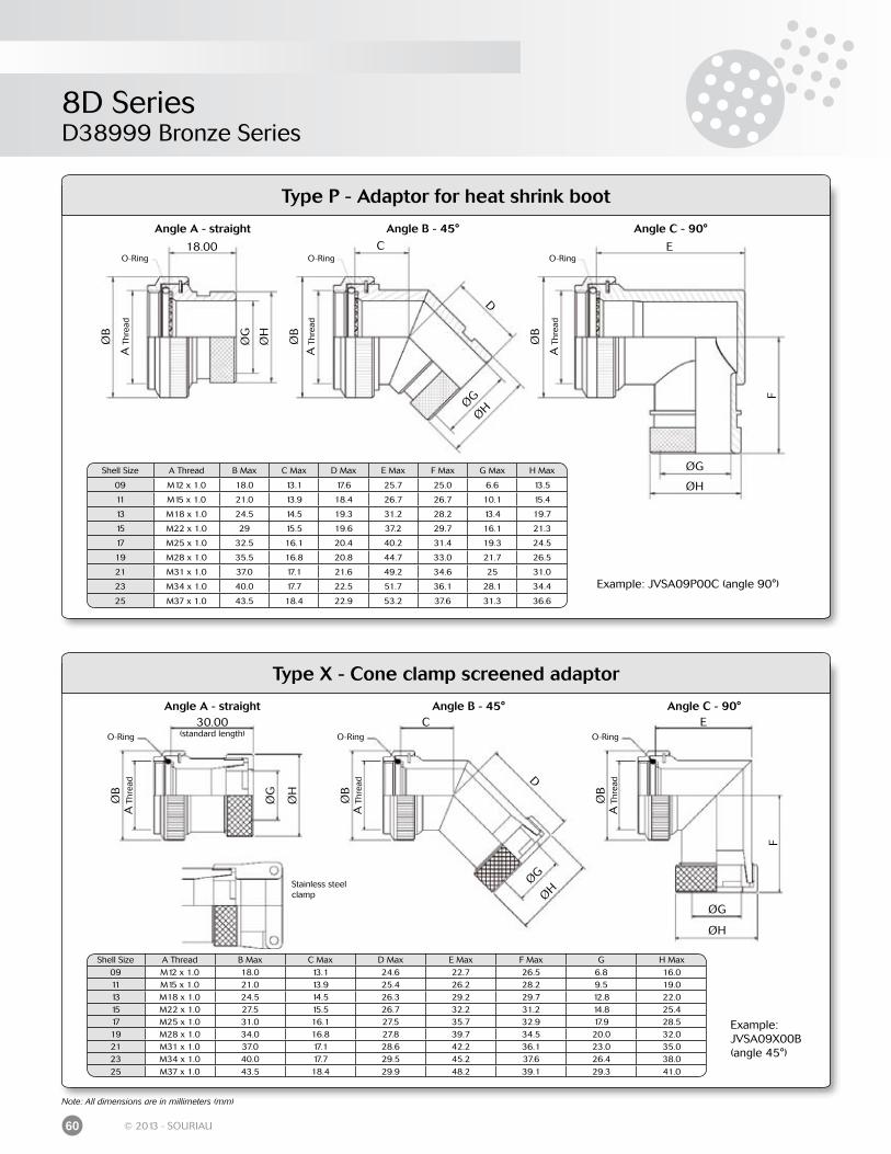
8D SeriesD38999 Bronze Series
60 © 2013 - SOURIAU
Angle B - 45°Angle A - straight Angle C - 90°
O-Ring
A T
hrea
d
18.00
A T
hrea
d
O-Ring O-Ring
A T
hrea
d
C E
D
ØG
ØH
ØB
ØB
ØB
ØG
ØH
ØG
ØH
F
Type X - Cone clamp screened adaptor
Type P - Adaptor for heat shrink boot
Shell Size A Thread B Max C Max D Max E Max F Max G Max H Max
09 M12 x 1.0 18.0 13.1 17.6 25.7 25.0 6.6 13.5
11 M15 x 1.0 21.0 13.9 18.4 26.7 26.7 10.1 15.4
13 M18 x 1.0 24.5 14.5 19.3 31.2 28.2 13.4 19.7
15 M22 x 1.0 29 15.5 19.6 37.2 29.7 16.1 21.3
17 M25 x 1.0 32.5 16.1 20.4 40.2 31.4 19.3 24.5
19 M28 x 1.0 35.5 16.8 20.8 44.7 33.0 21.7 26.5
21 M31 x 1.0 37.0 17.1 21.6 49.2 34.6 25 31.0
23 M34 x 1.0 40.0 17.7 22.5 51.7 36.1 28.1 34.4
25 M37 x 1.0 43.5 18.4 22.9 53.2 37.6 31.3 36.6
Shell Size A Thread B Max C Max D Max E Max F Max G H Max09 M12 x 1.0 18.0 13.1 24.6 22.7 26.5 6.8 16.011 M15 x 1.0 21.0 13.9 25.4 26.2 28.2 9.5 19.013 M18 x 1.0 24.5 14.5 26.3 29.2 29.7 12.8 22.015 M22 x 1.0 27.5 15.5 26.7 32.2 31.2 14.8 25.417 M25 x 1.0 31.0 16.1 27.5 35.7 32.9 17.9 28.519 M28 x 1.0 34.0 16.8 27.8 39.7 34.5 20.0 32.021 M31 x 1.0 37.0 17.1 28.6 42.2 36.1 23.0 35.023 M34 x 1.0 40.0 17.7 29.5 45.2 37.6 26.4 38.025 M37 x 1.0 43.5 18.4 29.9 48.2 39.1 29.3 41.0
Example: JVSA09P00C (angle 90°)
Example:JVSA09X00B(angle 45°)
Note: All dimensions are in millimeters (mm)
Stainless steel clamp
Angle B - 45°Angle A - straight Angle C - 90°
O-Ring
A T
hrea
d
A T
hrea
d
O-Ring O-Ring
A T
hrea
d
C E
D
ØG
ØH
ØB
ØB
ØB
ØG
ØH
ØG
ØH
F
30.00(standard length)
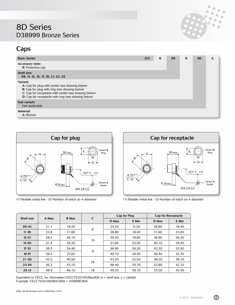
8D SeriesD38999 Bronze Series
61© 2013 - SOURIAU
Caps
Cap for plug Cap for receptacle
(1) Flexible metal link - (2) Number of notch on A diameter
Basic Series JVS B 09 B 00 A
Accessory style: B: Protective cap
Shell size: 09, 11, 13, 15, 17, 19, 21, 23, 25
Variant: A: Cap for plug with eyelet (see drawing below) B: Cap for plug with ring (see drawing below) C: Cap for receptacle with eyelet (see drawing below) D: Cap for receptacle with ring (see drawing below)
Sub variant: Not applicable
Material: A: Bronze
Equivalent to CECC, for information CECC75201002Bxy00A (x = shell size, y = variant)Example: CECC75201002BAC00A = JVSB09C00A
Note: All dimensions are in millimeters (mm)
Shell size A Max B Max CCap for Plug Cap for Receptacle
D Max E Min D Max E Min
09 (A) 21.1 19.208
24.20 13.50 26.80 18.40
11 (B) 23.8 21.80 26.80 18.40 31.60 23.00
13 (C) 28.2 26.1010
30.50 19.80 36.90 26.20
15 (D) 31.4 29.30 31.60 23.00 40.10 29.40
17 (E) 36.5 34.4012
36.90 26.20 43.20 32.50
19 (F) 39.3 37.20 40.10 29.40 46.40 35.70
21 (G) 42.5 40.5016
43.20 32.50 49.20 39.10
23 (H) 45.3 43.10 46.40 35.70 52.80 42.10
25 (J) 48.4 46.10 18 49.20 39.10 55.50 45.30
(1) Flexible metal link - (2) Number of notch on A diameter
A
B
C (2)4.75±0.13
30 Max
6.9 Max
E
D
Variant BRing
Variant AEyelet
127+13- 7
Ø4.24+0.25- 0.13
(1)
A
B
C (2)4.75±0.13
30 Max
11.9 Max
E
D
Variant BRing
Variant AEyelet
127+13- 7
Ø4.24+0.25- 0.13
(1)

8D Series
Contacts: Crimp contacts .......................................................................................................................... Straight PC tail contacts .......................................................................................................... Coax contacts #12 .................................................................................................................... Solder cup ................................................................................................................................... Crimp contacts: 1500 mating ................................................................................................ Wire wrap contacts ................................................................................................................... Quadrax #8 contacts ............................................................................................................... Thermocouple contacts .......................................................................................................... Dummy contacts ....................................................................................................................... Filler plugs ...................................................................................................................................
Wiring instruction ............................................................................................................................
Tooling: Crimping tools ............................................................................................................................ Insertion and extraction tools ............................................................................................... Backshell tightening tools ...................................................................................................... Tightening support ................................................................................................................... Slackening tools ........................................................................................................................
Accessories: Gaskets ......................................................................................................................................... Plastic protective caps .............................................................................................................
Orientations .......................................................................................................................................
Panel cut-out .....................................................................................................................................
Coordinates for straight PC tail terminations ..........................................................................
64666767676767686868
69
7071717171
7272
73 73
74
Common Section8D Series
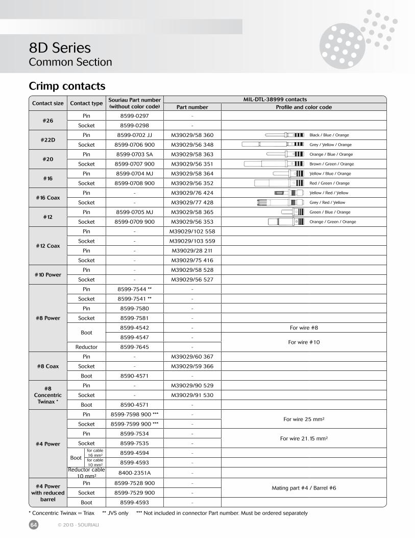
8D SeriesCommon Section
64 © 2013 - SOURIAU
Crimp contacts
* Concentric Twinax = Triax ** JVS only *** Not included in connector Part number. Must be ordered separately
Contact size Contact typeSouriau Part number (without color code)
MIL-DTL-38999 contactsPart number Profile and color code
#26Pin 8599-0297 -
Socket 8599-0298 -
#22DPin 8599-0702 JJ M39029/58 360 Black / Blue / Orange
Socket 8599-0706 900 M39029/56 348 Grey / Yellow / Orange
#20Pin 8599-0703 SA M39029/58 363 Orange / Blue / Orange
Socket 8599-0707 900 M39029/56 351 Brown / Green / Orange
#16Pin 8599-0704 MJ M39029/58 364 Yellow / Blue / Orange
Socket 8599-0708 900 M39029/56 352 Red / Green / Orange
#16 CoaxPin - M39029/76 424 Yellow / Red / Yellow
Socket - M39029/77 428 Grey / Red / Yellow
#12Pin 8599-0705 MJ M39029/58 365 Green / Blue / Orange
Socket 8599-0709 900 M39029/56 353 Orange / Green / Orange
#12 Coax
Pin - M39029/102 558
Socket - M39029/103 559
Pin - M39029/28 211
Socket - M39029/75 416
#10 PowerPin - M39029/58 528
Socket - M39029/56 527
#8 Power
Pin 8599-7544 ** -
Socket 8599-7541 ** -
Pin 8599-7580 -
Socket 8599-7581 -
Boot8599-4542 - For wire #8
8599-4547 -For wire #10
Reductor 8599-7645 -
#8 Coax
Pin - M39029/60 367
Socket - M39029/59 366
Boot 8590-4571 -
#8Concentric
Twinax *
Pin - M39029/90 529
Socket - M39029/91 530
Boot 8590-4571 -
#4 Power
Pin 8599-7598 900 *** -For wire 25 mm²
Socket 8599-7599 900 *** -
Pin 8599-7534 -For wire 21.15 mm²
Socket 8599-7535 -
Bootfor cable 16 mm² 8599-4594 -for cable 10 mm² 8599-4593 -
Reductor cable 10 mm²
8400-2351A -
#4 Powerwith reduced
barrel
Pin 8599-7528 900 -Mating part #4 / Barrel #6
Socket 8599-7529 900 -
Boot 8599-4593 -
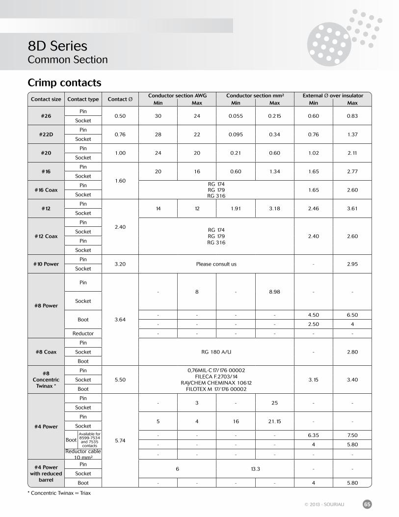
8D SeriesCommon Section
65© 2013 - SOURIAU
Crimp contactsContact size Contact type Contact Ø
Conductor section AWG Conductor section mm² External Ø over insulatorMin Max Min Max Min Max
#26Pin
0.50 30 24 0.055 0.215 0.60 0.83Socket
#22DPin
0.76 28 22 0.095 0.34 0.76 1.37Socket
#20Pin
1.00 24 20 0.21 0.60 1.02 2.11Socket
#16Pin
1.60
20 16 0.60 1.34 1.65 2.77Socket
#16 CoaxPin RG 174
RG 179RG 316
1.65 2.60Socket
#12Pin
2.40
14 12 1.91 3.18 2.46 3.61Socket
#12 Coax
PinRG 174RG 179RG 316
2.40 2.60Socket
Pin
Socket
#10 PowerPin
3.20 Please consult us - 2.95Socket
#8 Power
Pin
3.64
- 8 - 8.98 - -
Socket
Boot- - - - 4.50 6.50
- - - - 2.50 4
Reductor - - - - - -
#8 Coax
Pin
RG 180 A/U - 2.80Socket
Boot
#8Concentric
Twinax *
Pin
5.50
0,76MIL-C17/176 00002FILECA F.2703/14
RAYCHEM CHEMINAX 10612FILOTEX M 17/176 00002
3.15 3.40Socket
Boot
#4 Power
Pin
5.74
- 3 - 25 - -Socket
Pin5 4 16 21.15 - -
Socket
BootAvailable for 8599-7534 and 7535 contacts
- - - - 6.35 7.50
- - - - 4 5.80Reductor cable
10 mm²- - - - - -
#4 Powerwith reduced
barrel
Pin6 13.3 - -
Socket
Boot - - - - 4 5.80
* Concentric Twinax = Triax
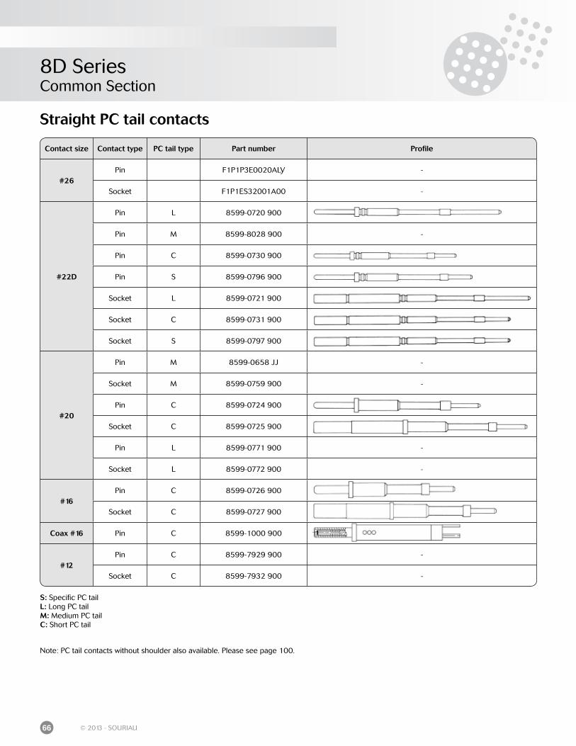
8D SeriesCommon Section
66 © 2013 - SOURIAU
Straight PC tail contacts
S: Specific PC tail L: Long PC tail M: Medium PC tail C: Short PC tail
Contact size Contact type PC tail type Part number Profile
#26Pin F1P1P3E0020ALY -
Socket F1P1ES32001A00 -
#22D
Pin L 8599-0720 900
Pin M 8599-8028 900 -
Pin C 8599-0730 900
Pin S 8599-0796 900
Socket L 8599-0721 900
Socket C 8599-0731 900
Socket S 8599-0797 900
#20
Pin M 8599-0658 JJ -
Socket M 8599-0759 900 -
Pin C 8599-0724 900
Socket C 8599-0725 900
Pin L 8599-0771 900 -
Socket L 8599-0772 900 -
#16Pin C 8599-0726 900
Socket C 8599-0727 900
Coax #16 Pin C 8599-1000 900
#12Pin C 8599-7929 900 -
Socket C 8599-7932 900 -
Note: PC tail contacts without shoulder also available. Please see page 100.
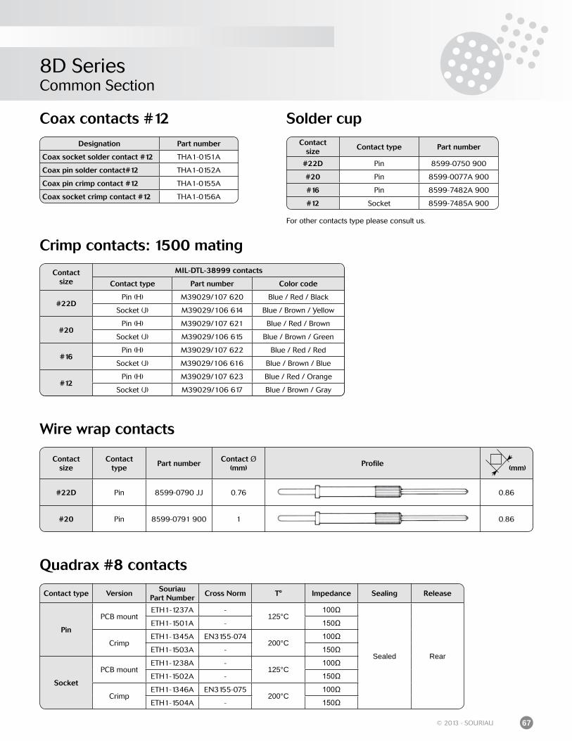
8D SeriesCommon Section
67© 2013 - SOURIAU
Crimp contacts: 1500 mating
Wire wrap contacts
Coax contacts #12 Solder cup
For other contacts type please consult us.
Designation Part number
Coax socket solder contact #12 THA1-0151A
Coax pin solder contact#12 THA1-0152A
Coax pin crimp contact #12 THA1-0155A
Coax socket crimp contact #12 THA1-0156A
Contactsize
Contact type Part number
#22D Pin 8599-0750 900
#20 Pin 8599-0077A 900
#16 Pin 8599-7482A 900
#12 Socket 8599-7485A 900
Contactsize
MIL-DTL-38999 contacts
Contact type Part number Color code
#22DPin (H) M39029/107 620 Blue / Red / Black
Socket (J) M39029/106 614 Blue / Brown / Yellow
#20Pin (H) M39029/107 621 Blue / Red / Brown
Socket (J) M39029/106 615 Blue / Brown / Green
#16Pin (H) M39029/107 622 Blue / Red / Red
Socket (J) M39029/106 616 Blue / Brown / Blue
#12Pin (H) M39029/107 623 Blue / Red / Orange
Socket (J) M39029/106 617 Blue / Brown / Gray
Contactsize
Contacttype
Part numberContact Ø
(mm)Profile
(mm)
#22D Pin 8599-0790 JJ 0.76 0.86
#20 Pin 8599-0791 900 1 0.86
Quadrax #8 contacts
Contact type VersionSouriau
Part NumberCross Norm T° Impedance Sealing Release
Pin
PCB mountETH1-1237A -
125°C100Ω
Sealed Rear
ETH1-1501A - 150Ω
CrimpETH1-1345A EN3155-074
200°C100Ω
ETH1-1503A - 150Ω
Socket
PCB mountETH1-1238A -
125°C100Ω
ETH1-1502A - 150Ω
CrimpETH1-1346A EN3155-075
200°C100Ω
ETH1-1504A - 150Ω
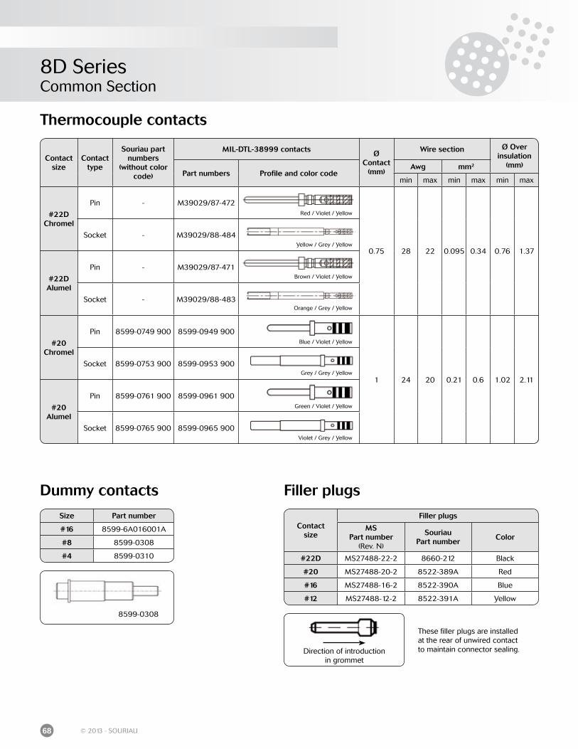
8D SeriesCommon Section
68 © 2013 - SOURIAU
Thermocouple contacts
Contact size
Contact type
Souriau part numbers
(without color code)
MIL-DTL-38999 contacts Ø Contact
(mm)
Wire section Ø Overinsulation
(mm)Part numbers Profile and color code
Awg mm2
min max min max min max
#22DChromel
Pin - M39029/87-472
0.75 28 22 0.095 0.34 0.76 1.37
Socket - M39029/88-484
#22DAlumel
Pin - M39029/87-471
Socket - M39029/88-483
#20Chromel
Pin 8599-0749 900 8599-0949 900
1 24 20 0.21 0.6 1.02 2.11
Socket 8599-0753 900 8599-0953 900
#20Alumel
Pin 8599-0761 900 8599-0961 900
Socket 8599-0765 900 8599-0965 900
Dummy contacts Filler plugs
Direction of introductionin grommet
Size Part number
#16 8599-6A016001A
#8 8599-0308
#4 8599-0310
Contactsize
Filler plugs
MSPart number
(Rev. N)
SouriauPart number
Color
#22D MS27488-22-2 8660-212 Black
#20 MS27488-20-2 8522-389A Red
#16 MS27488-16-2 8522-390A Blue
#12 MS27488-12-2 8522-391A Yellow
Red / Violet / Yellow
Yellow / Grey / Yellow
Brown / Violet / Yellow
Orange / Grey / Yellow
Blue / Violet / Yellow
Grey / Grey / Yellow
Green / Violet / Yellow
Violet / Grey / Yellow
8599-0308
These filler plugs are installed at the rear of unwired contact to maintain connector sealing.
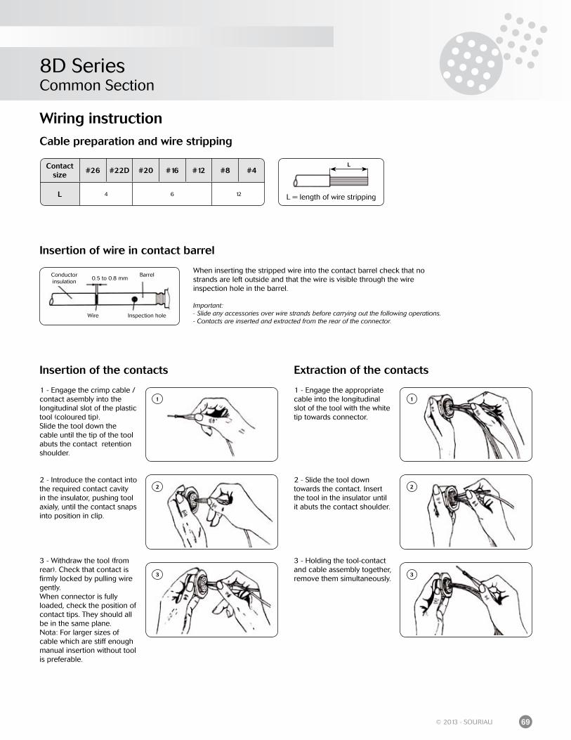
8D SeriesCommon Section
69© 2013 - SOURIAU
Wiring instructionCable preparation and wire stripping
L = length of wire stripping
LContact size
#26 #22D #20 #16 #12 #8 #4
L 4 6 12
Conductor insulation
Barrel
Inspection holeWire
0.5 to 0.8 mm
Insertion of wire in contact barrel
When inserting the stripped wire into the contact barrel check that no strands are left outside and that the wire is visible through the wireinspection hole in the barrel.
Important:- Slide any accessories over wire strands before carrying out the following operations. - Contacts are inserted and extracted from the rear of the connector.
Insertion of the contacts
1 - Engage the crimp cable / contact asembly into thelongitudinal slot of the plastic tool (coloured tip). Slide the tool down the cable until the tip of the tool abuts the contact retention shoulder.
2 - Introduce the contact into the required contact cavity in the insulator, pushing tool axialy, until the contact snaps into position in clip.
3 - Withdraw the tool (from rear). Check that contact is firmly locked by pulling wire gently. When connector is fully loaded, check the position of contact tips. They should all be in the same plane. Nota: For larger sizes of cable which are stiff enough manual insertion without tool is preferable.
1
2
3
Extraction of the contacts
1 - Engage the appropriate cable into the longitudinal slot of the tool with the white tip towards connector.
2 - Slide the tool down towards the contact. Insert the tool in the insulator until it abuts the contact shoulder.
3 - Holding the tool-contact and cable assembly together, remove them simultaneously.
1
2
3
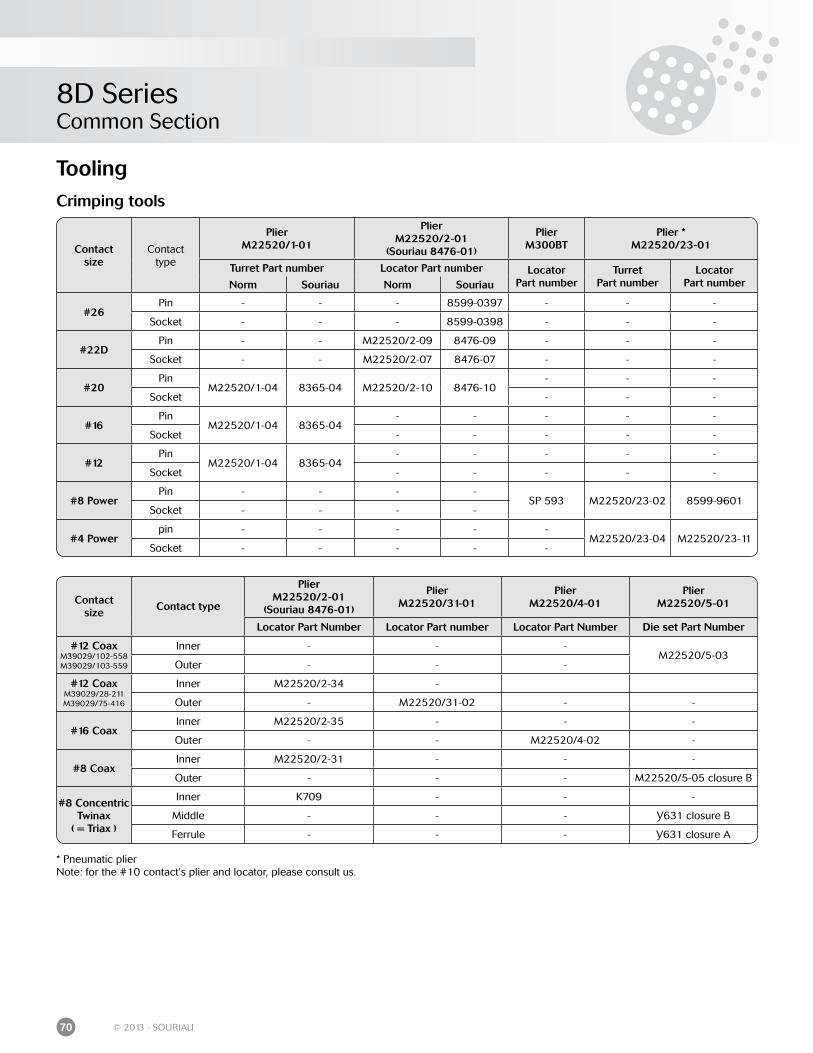
8D SeriesCommon Section
70 © 2013 - SOURIAU
Crimping tools
* Pneumatic plierNote: for the #10 contact’s plier and locator, please consult us.
Contactsize
Contacttype
PlierM22520/1-01
PlierM22520/2-01
(Souriau 8476-01)
PlierM300BT
Plier *M22520/23-01
Turret Part number Locator Part number LocatorPart number
TurretPart number
LocatorPart numberNorm Souriau Norm Souriau
#26Pin - - - 8599-0397 - - -
Socket - - - 8599-0398 - - -
#22DPin - - M22520/2-09 8476-09 - - -
Socket - - M22520/2-07 8476-07 - - -
#20Pin
M22520/1-04 8365-04 M22520/2-10 8476-10- - -
Socket - - -
#16Pin
M22520/1-04 8365-04- - - - -
Socket - - - - -
#12Pin
M22520/1-04 8365-04- - - - -
Socket - - - - -
#8 PowerPin - - - -
SP 593 M22520/23-02 8599-9601Socket - - - -
#4 Powerpin - - - - -
M22520/23-04 M22520/23-11Socket - - - - -
Contactsize
Contact type
PlierM22520/2-01
(Souriau 8476-01)
PlierM22520/31-01
PlierM22520/4-01
PlierM22520/5-01
Locator Part Number Locator Part number Locator Part Number Die set Part Number
#12 CoaxM39029/102-558M39029/103-559
Inner - - -M22520/5-03
Outer - - -
#12 CoaxM39029/28-211M39029/75-416
Inner M22520/2-34 -
Outer - M22520/31-02 - -
#16 CoaxInner M22520/2-35 - - -
Outer - - M22520/4-02 -
#8 CoaxInner M22520/2-31 - - -
Outer - - - M22520/5-05 closure B
#8 Concentric Twinax
( = Triax )
Inner K709 - - -
Middle - - - Y631 closure B
Ferrule - - - Y631 closure A
Tooling
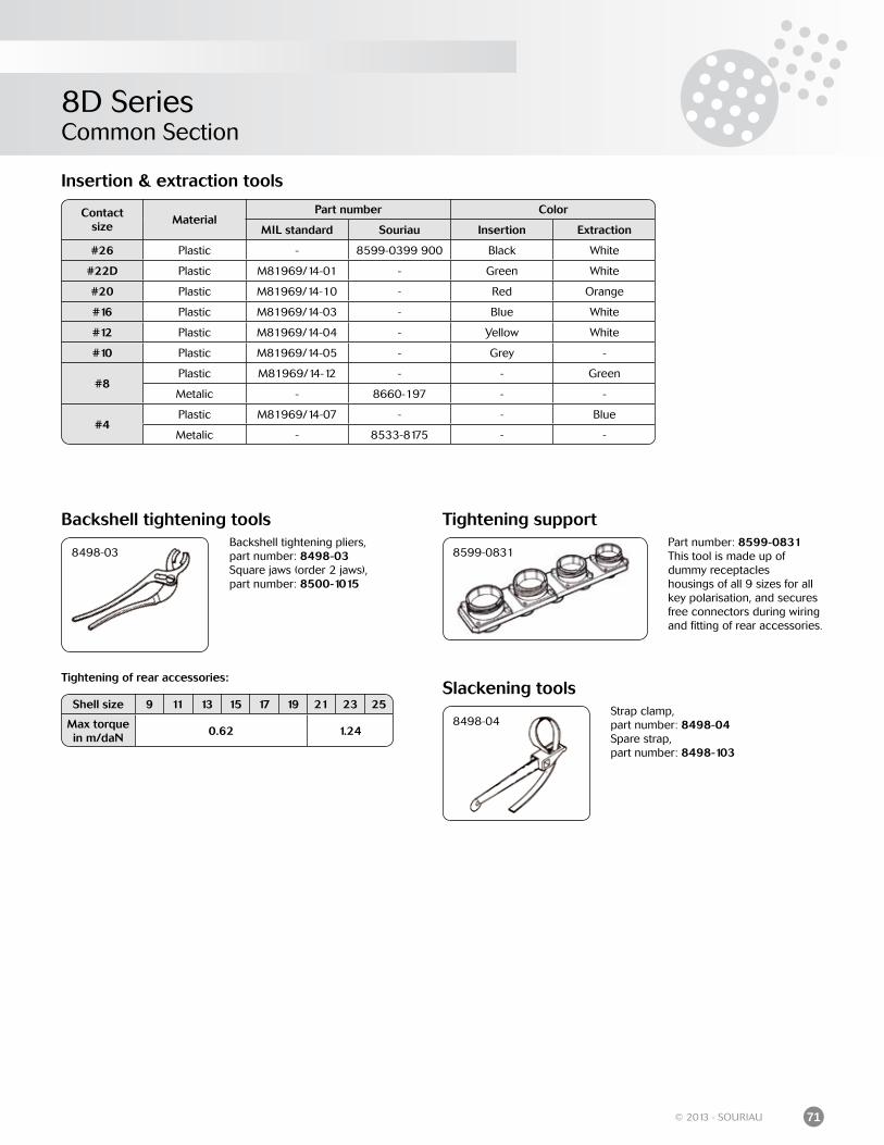
8D SeriesCommon Section
71© 2013 - SOURIAU
Tightening supportPart number: 8599-0831This tool is made up ofdummy receptacleshousings of all 9 sizes for all key polarisation, and secures free connectors during wiring and fitting of rear accessories.
8599-0831
Backshell tightening tools
8498-03Backshell tightening pliers,part number: 8498-03Square jaws (order 2 jaws),part number: 8500-1015
Tightening of rear accessories:
Shell size 9 11 13 15 17 19 21 23 25
Max torque in m/daN
0.62 1.24
Strap clamp,part number: 8498-04 Spare strap,part number: 8498-103
Slackening tools
8498-04
Insertion & extraction tools
Contactsize
MaterialPart number Color
MIL standard Souriau Insertion Extraction
#26 Plastic - 8599-0399 900 Black White
#22D Plastic M81969/14-01 - Green White
#20 Plastic M81969/14-10 - Red Orange
#16 Plastic M81969/14-03 - Blue White
#12 Plastic M81969/14-04 - Yellow White
#10 Plastic M81969/14-05 - Grey -
#8Plastic M81969/14-12 - - Green
Metalic - 8660-197 - -
#4Plastic M81969/14-07 - - Blue
Metalic - 8533-8175 - -
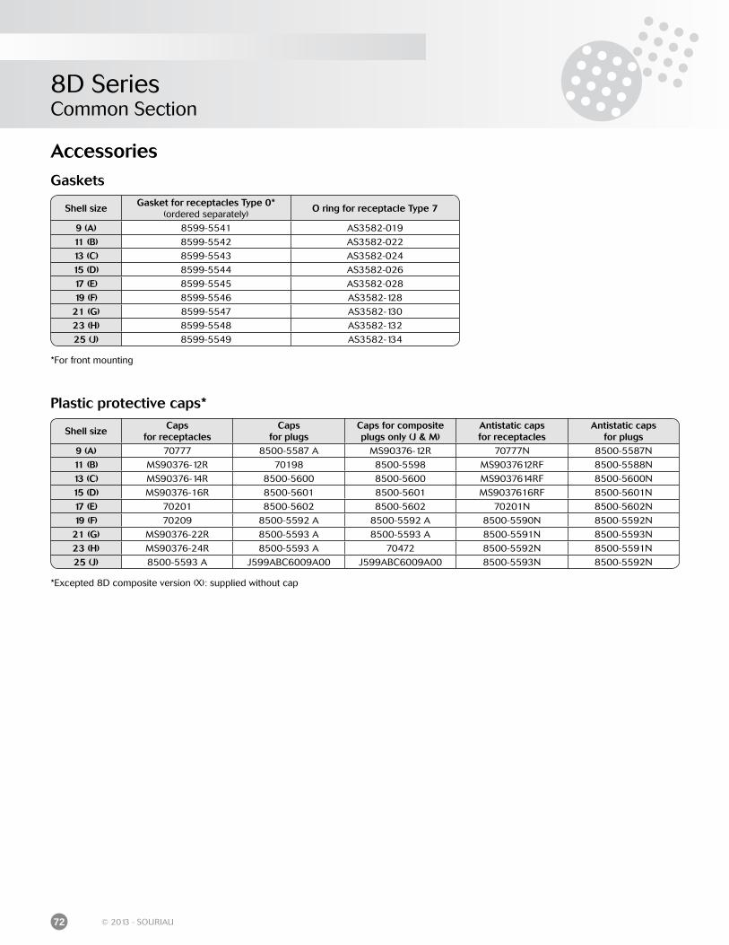
8D SeriesCommon Section
72 © 2013 - SOURIAU
Plastic protective caps*
*Excepted 8D composite version (X): supplied without cap
Shell sizeCaps
for receptaclesCaps
for plugsCaps for composite plugs only (J & M)
Antistatic capsfor receptacles
Antistatic capsfor plugs
9 (A) 70777 8500-5587 A MS90376-12R 70777N 8500-5587N
11 (B) MS90376-12R 70198 8500-5598 MS9037612RF 8500-5588N
13 (C) MS90376-14R 8500-5600 8500-5600 MS9037614RF 8500-5600N
15 (D) MS90376-16R 8500-5601 8500-5601 MS9037616RF 8500-5601N
17 (E) 70201 8500-5602 8500-5602 70201N 8500-5602N
19 (F) 70209 8500-5592 A 8500-5592 A 8500-5590N 8500-5592N
21 (G) MS90376-22R 8500-5593 A 8500-5593 A 8500-5591N 8500-5593N
23 (H) MS90376-24R 8500-5593 A 70472 8500-5592N 8500-5591N
25 (J) 8500-5593 A J599ABC6009A00 J599ABC6009A00 8500-5593N 8500-5592N
Gaskets
*For front mounting
Shell sizeGasket for receptacles Type 0*
(ordered separately)O ring for receptacle Type 7
9 (A) 8599-5541 AS3582-019
11 (B) 8599-5542 AS3582-022
13 (C) 8599-5543 AS3582-024
15 (D) 8599-5544 AS3582-026
17 (E) 8599-5545 AS3582-028
19 (F) 8599-5546 AS3582-128
21 (G) 8599-5547 AS3582-130
23 (H) 8599-5548 AS3582-132
25 (J) 8599-5549 AS3582-134
Accessories
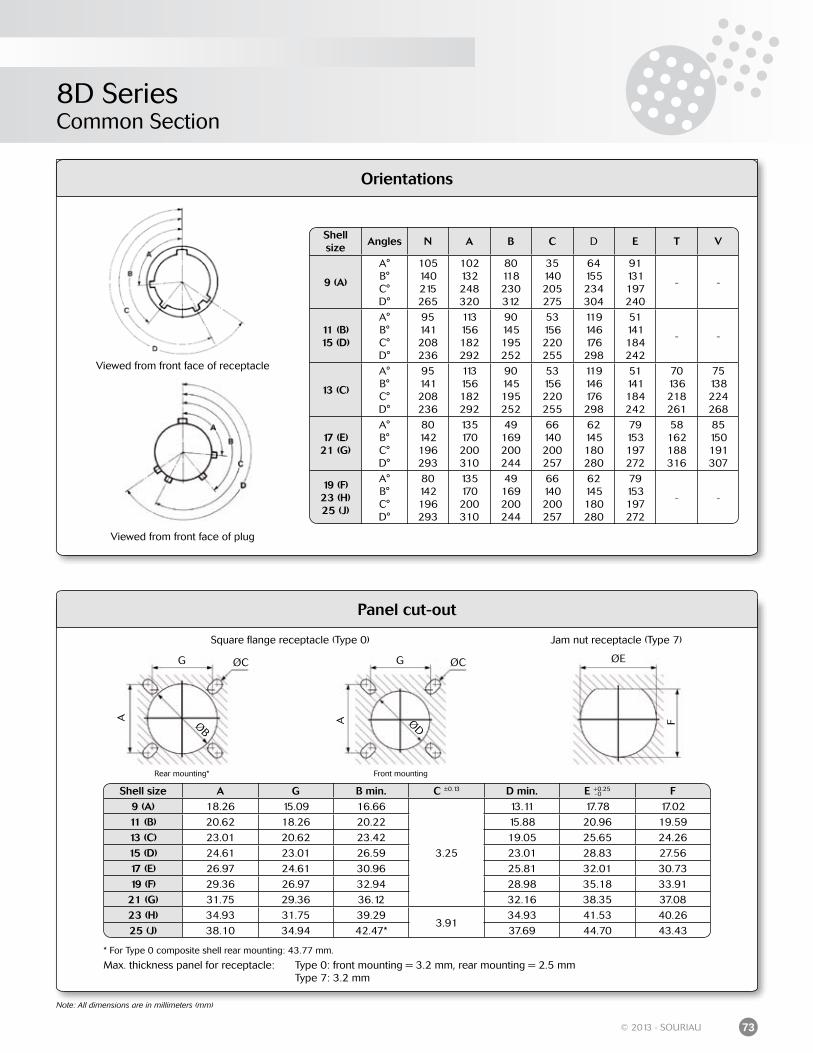
8D SeriesCommon Section
73© 2013 - SOURIAU
Panel cut-out
Max. thickness panel for receptacle: Type 0: front mounting = 3.2 mm, rear mounting = 2.5 mm Type 7: 3.2 mm
Rear mounting* Front mounting
Square flange receptacle (Type 0) Jam nut receptacle (Type 7)
ØEØCØC
ØDØB
G G
A A F
Note: All dimensions are in millimeters (mm)
* For Type 0 composite shell rear mounting: 43.77 mm.
Orientations
Viewed from front face of receptacle
Viewed from front face of plug
Shell size
Angles N A B C D E T V
9 (A)
A°B°C°D°
105140215265
102132248320
80118230312
35140205275
64155234304
91131197240
- -
11 (B) 15 (D)
A°B°C°D°
95141208236
113156182292
90145195252
53156220255
119146176298
51141184242
- -
13 (C)
A°B°C°D°
95141208236
113156182292
90145195252
53156220255
119146176298
51141184242
70136218261
75138224268
17 (E)21 (G)
A°B°C°D°
80142196293
135170200310
49169200244
66140200257
62145180280
79153197272
58162188316
85150191307
19 (F)23 (H)25 (J)
A°B°C°D°
80142196293
135170200310
49169200244
66140200257
62145180280
79153197272
- -
Shell size A G B min. C ±0.13 D min. E +0.25 F9 (A) 18.26 15.09 16.66
3.25
13.11 17.78 17.02
11 (B) 20.62 18.26 20.22 15.88 20.96 19.59
13 (C) 23.01 20.62 23.42 19.05 25.65 24.26
15 (D) 24.61 23.01 26.59 23.01 28.83 27.56
17 (E) 26.97 24.61 30.96 25.81 32.01 30.73
19 (F) 29.36 26.97 32.94 28.98 35.18 33.91
21 (G) 31.75 29.36 36.12 32.16 38.35 37.08
23 (H) 34.93 31.75 39.293.91
34.93 41.53 40.26
25 (J) 38.10 34.94 42.47* 37.69 44.70 43.43
- 0
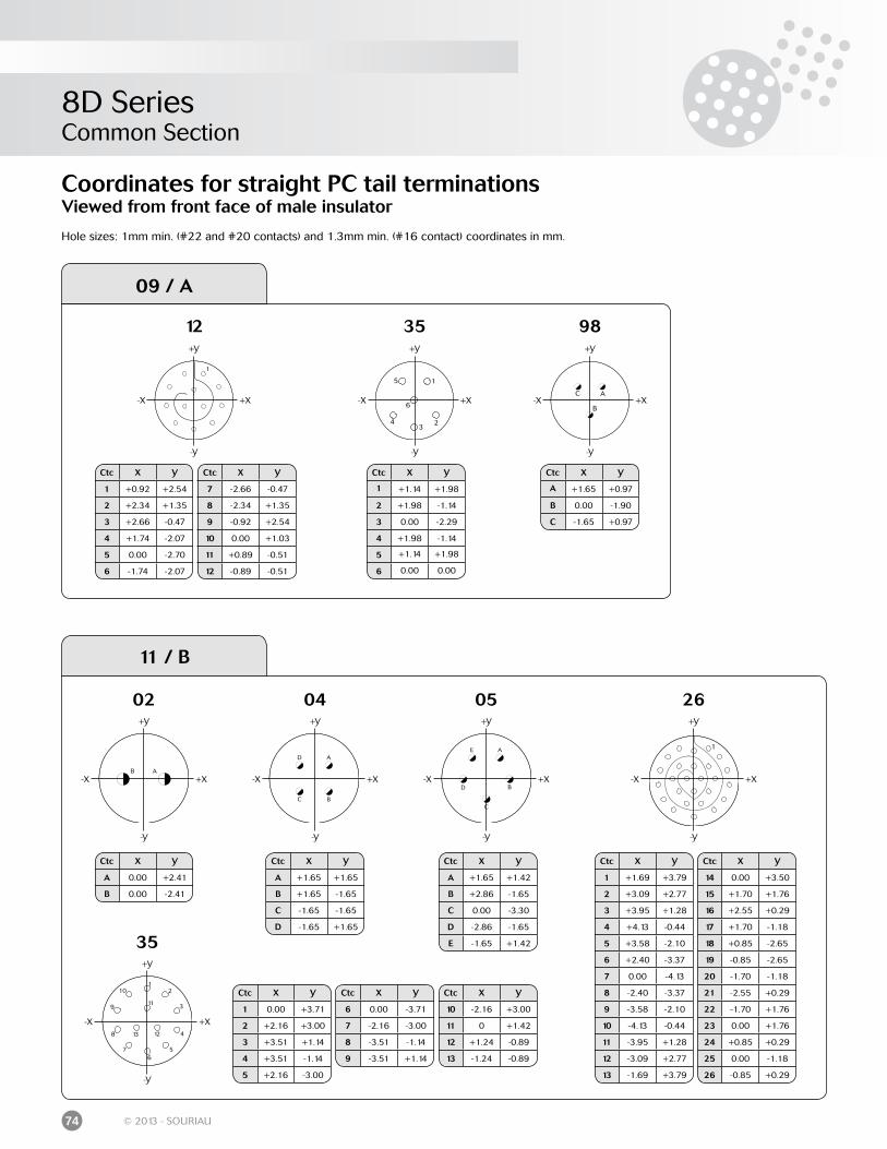
8D SeriesCommon Section
74 © 2013 - SOURIAU
Ctc X Y
7 -2.66 -0.47
8 -2.34 +1.35
9 -0.92 +2.54
10 0.00 +1.03
11 +0.89 -0.51
12 -0.89 -0.51
12
+X-X
+Y
-Y
Ctc X Y
1 +0.92 +2.54
2 +2.34 +1.35
3 +2.66 -0.47
4 +1.74 -2.07
5 0.00 -2.70
6 -1.74 -2.07
09 / A
Coordinates for straight PC tail terminationsViewed from front face of male insulator
Hole sizes: 1mm min. (#22 and #20 contacts) and 1.3mm min. (#16 contact) coordinates in mm.
98
+X-X
+Y
-Y
Ctc X Y
A +1.65 +0.97
B 0.00 -1.90
C -1.65 +0.97
35
+X-X
+Y
-Y
Ctc X Y
1 +1.14 +1.98
2 +1.98 -1.14
3 0.00 -2.29
4 +1.98 -1.14
5 +1.14 +1.98
6 0.00 0.00
05
+X-X
+Y
-Y
Ctc X Y
A +1.65 +1.42
B +2.86 -1.65
C 0.00 -3.30
D -2.86 -1.65
E -1.65 +1.42
04
+X-X
+Y
-Y
Ctc X Y
A +1.65 +1.65
B +1.65 -1.65
C -1.65 -1.65
D -1.65 +1.65
+X-X
+Y
-Y
02
Ctc X Y
A 0.00 +2.41
B 0.00 -2.41
11 / B
Ctc X Y
1 +1.69 +3.79
2 +3.09 +2.77
3 +3.95 +1.28
4 +4.13 -0.44
5 +3.58 -2.10
6 +2.40 -3.37
7 0.00 -4.13
8 -2.40 -3.37
9 -3.58 -2.10
10 -4.13 -0.44
11 -3.95 +1.28
12 -3.09 +2.77
13 -1.69 +3.79
Ctc X Y
14 0.00 +3.50
15 +1.70 +1.76
16 +2.55 +0.29
17 +1.70 -1.18
18 +0.85 -2.65
19 -0.85 -2.65
20 -1.70 -1.18
21 -2.55 +0.29
22 -1.70 +1.76
23 0.00 +1.76
24 +0.85 +0.29
25 0.00 -1.18
26 -0.85 +0.29
26
+X-X
+Y
-Y
35
+X-X
+Y
-Y
Ctc X Y
1 0.00 +3.71
2 +2.16 +3.00
3 +3.51 +1.14
4 +3.51 -1.14
5 +2.16 -3.00
Ctc X Y
10 -2.16 +3.00
11 0 +1.42
12 +1.24 -0.89
13 -1.24 -0.89
Ctc X Y
6 0.00 -3.71
7 -2.16 -3.00
8 -3.51 -1.14
9 -3.51 +1.14
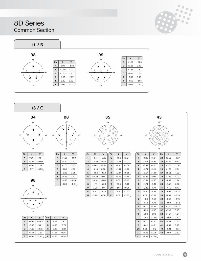
8D SeriesCommon Section
75© 2013 - SOURIAU
Ctc X Y
A 0.00 +3.30
B +3.30 0.00
C +1.65 -2.87
D -1.65 -2.87
E -3.30 0.00
F 0.00 0.00
+X-X
+Y
-Y
04 35
+X-X
+Y
-Y
Ctc X Y
12 -4.62 +2.24
13 -3.20 +4.01
14 -1.14 +5.00
15 +1.14 +2.72
16 +2.97 +0.66
17 +2.36 -1.91
18 0.00 -3.05
19 -2.36 -1.91
20 -2.97 +0.66
21 -1.14 +2.72
22 0.00 -0.76
Ctc X Y
1 +1.14 +5.00
2 +3.20 +4.01
3 +4.62 +2.24
4 +5.16 0.00
5 +4.62 -2.24
6 +3.20 -4.01
7 +1.14 -5.00
8 -1.14 -5.00
9 -3.20 -4.01
10 -4.62 -2.24
11 -5.16 0.00
Ctc X Y
A 0.00 +3.81
B +3.71 +0.89
C 0.00 -2.11
D -3.71 +0.89
08
+X-X
+Y
-Y
Ctc X Y
A +1.65 +3.99
B +4.32 0.00
C +3.05 -3.05
D 0.00 -4.32
E -3.05 -3.05
F -4.32 0.00
G -1.65 +3.99
H 0.00 +1.12
13 / C
11 / B
98
+X-X
+Y
-Y
99
+X-X
+Y
-Y
Ctc X Y
A +1.65 +2.85
B +3.30 0.00
C +1.65 -2.87
D -1.65 -2.87
E -3.30 0.00
F -1.65 +2.87
G 0.00 0.00
98
+X-X
+Y
-Y
Ctc X Y
A 0.00 +4.95
B +3.18 +3.81
C +4.90 +0.76
D +4.17 -2.67
E 0.00 -3.43
Ctc X Y
F -4.17 -2.67
G -4.90 +0.76
H -3.18 +3.81
J +1.65 -0.38
K -1.65 -0.38
Ctc X Y
23 +3.92 +1.27
24 +4.10 -0.43
25 +3.57 -2.06
26 +1.99 -2.74
27 +0.86 -4.03
28 -0.86 -4.03
29 -1.99 -2.74
30 -3.57 -2.06
31 -4.10 -0.43
32 -3.92 +1.27
33 -2.54 +2.28
34 -1.68 +3.76
35 0.00 +2.42
36 +1.21 +1.21
37 +2.42 0.00
38 +1.21 -1.21
39 0.00 -2.42
40 -1.21 -1.21
41 -2.42 0.00
42 -1.21 +1.21
43 0.00 0.00
Ctc X Y
1 +1.80 +5.54
2 -1.80 +5.54
3 +3.42 +4.71
4 +4.71 +3.42
5 +5.54 +1.80
6 +5.82 0.00
7 +5.54 -1.80
8 +4.71 -3.42
9 +3.42 -4.71
10 +1.80 -5.54
11 0.00 -5.82
12 -1.80 -5.54
13 -3.42 -4.71
14 -4.71 -3.42
15 -5.54 -1.80
16 -5.82 0.00
17 -5.54 +1.80
18 -4.71 +3.42
19 -3.42 +4.71
20 0.00 +4.12
21 +1.68 +3.76
22 +2.54 +2.28
43
+X-X
+Y
-Y
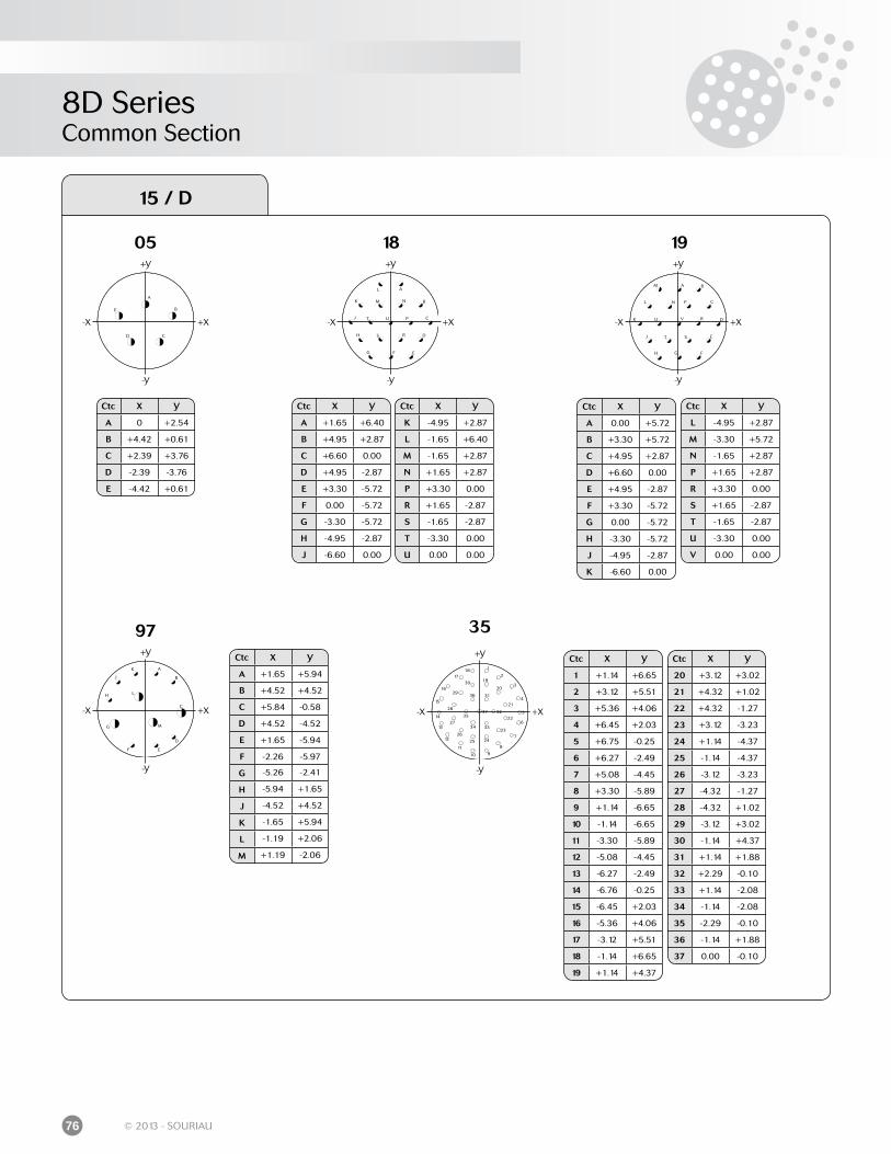
8D SeriesCommon Section
76 © 2013 - SOURIAU
35
+X-X
+Y
-Y
Ctc X Y
20 +3.12 +3.02
21 +4.32 +1.02
22 +4.32 -1.27
23 +3.12 -3.23
24 +1.14 -4.37
25 -1.14 -4.37
26 -3.12 -3.23
27 -4.32 -1.27
28 -4.32 +1.02
29 -3.12 +3.02
30 -1.14 +4.37
31 +1.14 +1.88
32 +2.29 -0.10
33 +1.14 -2.08
34 -1.14 -2.08
35 -2.29 -0.10
36 -1.14 +1.88
37 0.00 -0.10
Ctc X Y
1 +1.14 +6.65
2 +3.12 +5.51
3 +5.36 +4.06
4 +6.45 +2.03
5 +6.75 -0.25
6 +6.27 -2.49
7 +5.08 -4.45
8 +3.30 -5.89
9 +1.14 -6.65
10 -1.14 -6.65
11 -3.30 -5.89
12 -5.08 -4.45
13 -6.27 -2.49
14 -6.76 -0.25
15 -6.45 +2.03
16 -5.36 +4.06
17 -3.12 +5.51
18 -1.14 +6.65
19 +1.14 +4.37
97
+X-X
+Y
-Y
Ctc X Y
A +1.65 +5.94
B +4.52 +4.52
C +5.84 -0.58
D +4.52 -4.52
E +1.65 -5.94
F -2.26 -5.97
G -5.26 -2.41
H -5.94 +1.65
J -4.52 +4.52
K -1.65 +5.94
L -1.19 +2.06
M +1.19 -2.06
15 / D
18
+X-X
+Y
-Y
Ctc X Y
A +1.65 +6.40
B +4.95 +2.87
C +6.60 0.00
D +4.95 -2.87
E +3.30 -5.72
F 0.00 -5.72
G -3.30 -5.72
H -4.95 -2.87
J -6.60 0.00
Ctc X Y
K -4.95 +2.87
L -1.65 +6.40
M -1.65 +2.87
N +1.65 +2.87
P +3.30 0.00
R +1.65 -2.87
S -1.65 -2.87
T -3.30 0.00
U 0.00 0.00
05
+X-X
+Y
-Y
Ctc X Y
A 0 +2.54
B +4.42 +0.61
C +2.39 +3.76
D -2.39 -3.76
E -4.42 +0.61
19
+X-X
+Y
-Y
Ctc X Y
A 0.00 +5.72
B +3.30 +5.72
C +4.95 +2.87
D +6.60 0.00
E +4.95 -2.87
F +3.30 -5.72
G 0.00 -5.72
H -3.30 -5.72
J -4.95 -2.87
K -6.60 0.00
Ctc X Y
L -4.95 +2.87
M -3.30 +5.72
N -1.65 +2.87
P +1.65 +2.87
R +3.30 0.00
S +1.65 -2.87
T -1.65 -2.87
U -3.30 0.00
V 0.00 0.00
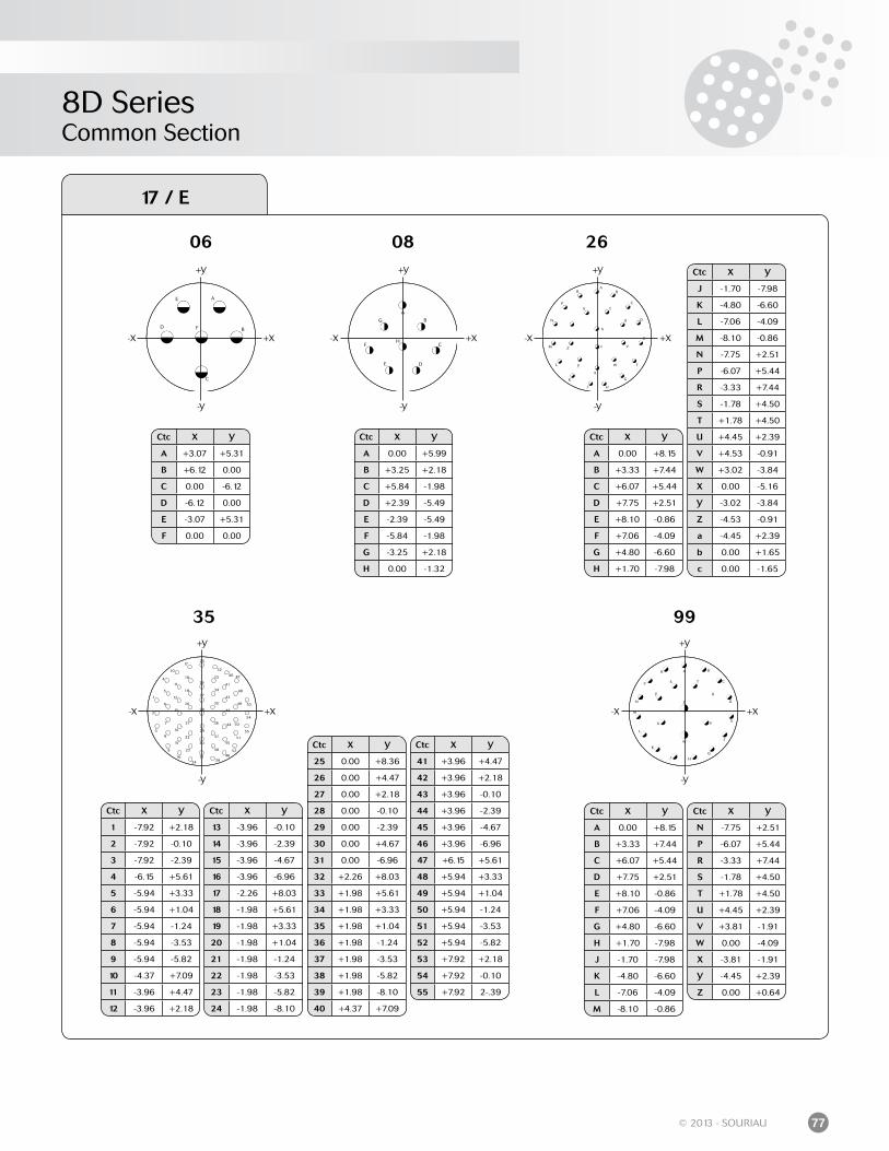
8D SeriesCommon Section
77© 2013 - SOURIAU
35
+X-X
+Y
-Y
99
+X-X
+Y
-Y
17 / E
06
+X-X
+Y
-Y
Ctc X Y
A +3.07 +5.31
B +6.12 0.00
C 0.00 -6.12
D -6.12 0.00
E -3.07 +5.31
F 0.00 0.00
08
+X-X
+Y
-Y
Ctc X Y
A 0.00 +5.99
B +3.25 +2.18
C +5.84 -1.98
D +2.39 -5.49
E -2.39 -5.49
F -5.84 -1.98
G -3.25 +2.18
H 0.00 -1.32
26
+X-X
+Y
-Y
Ctc X Y
A 0.00 +8.15
B +3.33 +7.44
C +6.07 +5.44
D +7.75 +2.51
E +8.10 -0.86
F +7.06 -4.09
G +4.80 -6.60
H +1.70 -7.98
Ctc X Y
J -1.70 -7.98
K -4.80 -6.60
L -7.06 -4.09
M -8.10 -0.86
N -7.75 +2.51
P -6.07 +5.44
R -3.33 +7.44
S -1.78 +4.50
T +1.78 +4.50
U +4.45 +2.39
V +4.53 -0.91
W +3.02 -3.84
X 0.00 -5.16
Y -3.02 -3.84
Z -4.53 -0.91
a -4.45 +2.39
b 0.00 +1.65
c 0.00 -1.65
Ctc X Y
A 0.00 +8.15
B +3.33 +7.44
C +6.07 +5.44
D +7.75 +2.51
E +8.10 -0.86
F +7.06 -4.09
G +4.80 -6.60
H +1.70 -7.98
J -1.70 -7.98
K -4.80 -6.60
L -7.06 -4.09
M -8.10 -0.86
Ctc X Y
N -7.75 +2.51
P -6.07 +5.44
R -3.33 +7.44
S -1.78 +4.50
T +1.78 +4.50
U +4.45 +2.39
V +3.81 -1.91
W 0.00 -4.09
X -3.81 -1.91
Y -4.45 +2.39
Z 0.00 +0.64
Ctc X Y
25 0.00 +8.36
26 0.00 +4.47
27 0.00 +2.18
28 0.00 -0.10
29 0.00 -2.39
30 0.00 +4.67
31 0.00 -6.96
32 +2.26 +8.03
33 +1.98 +5.61
34 +1.98 +3.33
35 +1.98 +1.04
36 +1.98 -1.24
37 +1.98 -3.53
38 +1.98 -5.82
39 +1.98 -8.10
40 +4.37 +7.09
Ctc X Y
13 -3.96 -0.10
14 -3.96 -2.39
15 -3.96 -4.67
16 -3.96 -6.96
17 -2.26 +8.03
18 -1.98 +5.61
19 -1.98 +3.33
20 -1.98 +1.04
21 -1.98 -1.24
22 -1.98 -3.53
23 -1.98 -5.82
24 -1.98 -8.10
Ctc X Y
41 +3.96 +4.47
42 +3.96 +2.18
43 +3.96 -0.10
44 +3.96 -2.39
45 +3.96 -4.67
46 +3.96 -6.96
47 +6.15 +5.61
48 +5.94 +3.33
49 +5.94 +1.04
50 +5.94 -1.24
51 +5.94 -3.53
52 +5.94 -5.82
53 +7.92 +2.18
54 +7.92 -0.10
55 +7.92 2-.39
Ctc X Y
1 -7.92 +2.18
2 -7.92 -0.10
3 -7.92 -2.39
4 -6.15 +5.61
5 -5.94 +3.33
6 -5.94 +1.04
7 -5.94 -1.24
8 -5.94 -3.53
9 -5.94 -5.82
10 -4.37 +7.09
11 -3.96 +4.47
12 -3.96 +2.18
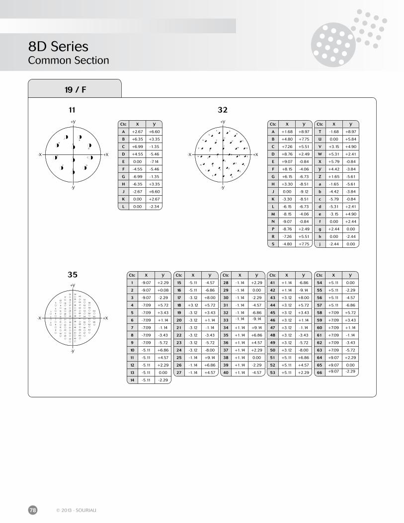
8D SeriesCommon Section
78 © 2013 - SOURIAU
35
+X-X
+Y
-Y
Ctc X Y
15 -5.11 -4.57
16 -5.11 -6.86
17 -3.12 +8.00
18 +3.12 +5.72
19 -3.12 +3.43
20 -3.12 +1.14
21 -3.12 -1.14
22 -3.12 -3.43
23 -3.12 -5.72
24 -3.12 -8.00
25 -1.14 +9.14
26 -1.14 +6.86
27 -1.14 +4.57
Ctc X Y
1 -9.07 +2.29
2 -9.07 +0.08
3 -9.07 -2.29
4 -7.09 +5.72
5 -7.09 +3.43
6 -7.09 +1.14
7 -7.09 -1.14
8 -7.09 -3.43
9 -7.09 -5.72
10 -5.11 +6.86
11 -5.11 +4.57
12 -5.11 +2.29
13 -5.11 0.00
14 -5.11 -2.29
Ctc X Y
28 -1.14 +2.29
29 -1.14 0.00
30 -1.14 -2.29
31 -1.14 -4.57
32 -1.14 -6.86
33 -1.14 -9.14
34 +1.14 +9.14
35 +1.14 +6.86
36 +1.14 +4.57
37 +1.14 +2.29
38 +1.14 0.00
39 +1.14 -2.29
40 +1.14 -4.57
Ctc X Y
41 +1.14 -6.86
42 +1.14 -9.14
43 +3.12 +8.00
44 +3.12 +5.72
45 +3.12 +3.43
46 +3.12 +1.14
47 +3.12 -1.14
48 +3.12 -3.43
49 +3.12 -5.72
50 +3.12 -8.00
51 +5.11 +6.86
52 +5.11 +4.57
53 +5.11 +2.29
Ctc X Y
54 +5.11 0.00
55 +5.11 -2.29
56 +5.11 -4.57
57 +5.11 -6.86
58 +7.09 +5.72
59 +7.09 +3.43
60 +7.09 +1.14
61 +7.09 -1.14
62 +7.09 -3.43
63 +7.09 -5.72
64 +9.07 +2.29
65 +9.07 0.00
66 +9.07 -2.29
19 / F
11 32
+X-X
+Y
-Y
+X-X
+Y
-Y
Ctc X Y
A +2.67 +6.60
B +6.35 +3.35
C +6.99 -1.35
D +4.55 -5.46
E 0.00 -7.14
F -4.55 -5.46
G -6.99 -1.35
H -6.35 +3.35
J -2.67 +6.60
K 0.00 +2.67
L 0.00 -2.34
Ctc X Y
T -1.68 +8.97
U 0.00 +5.84
V +3.15 +4.90
W +5.31 +2.41
X +5.79 -0.84
Y +4.42 -3.84
Z +1.65 -5.61
a -1.65 -5.61
b -4.42 -3.84
c -5.79 -0.84
d -5.31 +2.41
e -3.15 +4.90
f 0.00 +2.44
g +2.44 0.00
h 0.00 -2.44
j -2.44 0.00
Ctc X Y
A +1.68 +8.97
B +4.80 +7.75
C +7.26 +5.51
D +8.76 +2.49
E +9.07 -0.84
F +8.15 -4.06
G +6.15 -6.73
H +3.30 -8.51
J 0.00 -9.12
K -3.30 -8.51
L -6.15 -6.73
M -8.15 -4.06
N -9.07 -0.84
P -8.76 +2.49
R -7.26 +5.51
S -4.80 +7.75
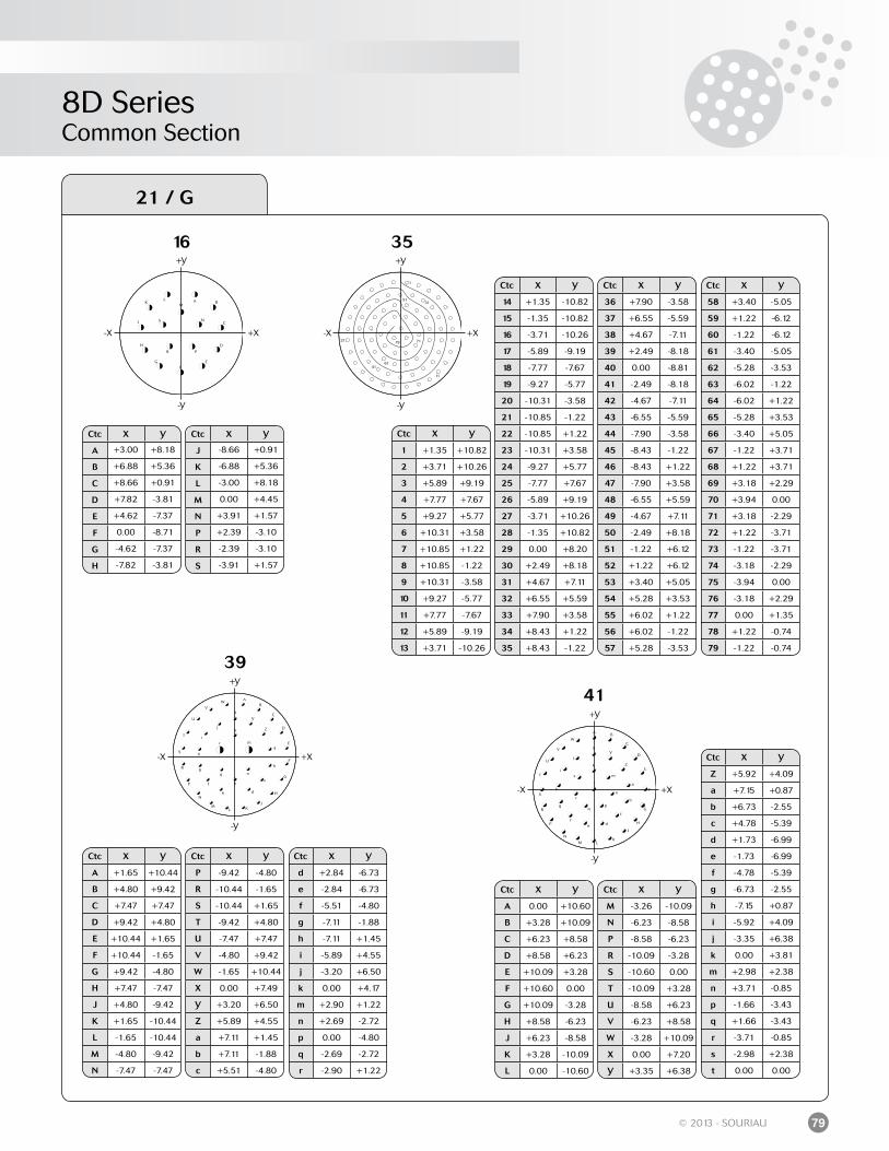
8D SeriesCommon Section
79© 2013 - SOURIAU
41
+X-X
+Y
-Y
39
+X-X
+Y
-Y
21 / G
16
+X-X
+Y
-Y
35
+X-X
+Y
-Y
Ctc X Y
1 +1.35 +10.82
2 +3.71 +10.26
3 +5.89 +9.19
4 +7.77 +7.67
5 +9.27 +5.77
6 +10.31 +3.58
7 +10.85 +1.22
8 +10.85 -1.22
9 +10.31 -3.58
10 +9.27 -5.77
11 +7.77 -7.67
12 +5.89 -9.19
13 +3.71 -10.26
Ctc X Y
14 +1.35 -10.82
15 -1.35 -10.82
16 -3.71 -10.26
17 -5.89 -9.19
18 -7.77 -7.67
19 -9.27 -5.77
20 -10.31 -3.58
21 -10.85 -1.22
22 -10.85 +1.22
23 -10.31 +3.58
24 -9.27 +5.77
25 -7.77 +7.67
26 -5.89 +9.19
27 -3.71 +10.26
28 -1.35 +10.82
29 0.00 +8.20
30 +2.49 +8.18
31 +4.67 +7.11
32 +6.55 +5.59
33 +7.90 +3.58
34 +8.43 +1.22
35 +8.43 -1.22
Ctc X Y
36 +7.90 -3.58
37 +6.55 -5.59
38 +4.67 -7.11
39 +2.49 -8.18
40 0.00 -8.81
41 -2.49 -8.18
42 -4.67 -7.11
43 -6.55 -5.59
44 -7.90 -3.58
45 -8.43 -1.22
46 -8.43 +1.22
47 -7.90 +3.58
48 -6.55 +5.59
49 -4.67 +7.11
50 -2.49 +8.18
51 -1.22 +6.12
52 +1.22 +6.12
53 +3.40 +5.05
54 +5.28 +3.53
55 +6.02 +1.22
56 +6.02 -1.22
57 +5.28 -3.53
Ctc X Y
58 +3.40 -5.05
59 +1.22 -6.12
60 -1.22 -6.12
61 -3.40 -5.05
62 -5.28 -3.53
63 -6.02 -1.22
64 -6.02 +1.22
65 -5.28 +3.53
66 -3.40 +5.05
67 -1.22 +3.71
68 +1.22 +3.71
69 +3.18 +2.29
70 +3.94 0.00
71 +3.18 -2.29
72 +1.22 -3.71
73 -1.22 -3.71
74 -3.18 -2.29
75 -3.94 0.00
76 -3.18 +2.29
77 0.00 +1.35
78 +1.22 -0.74
79 -1.22 -0.74
Ctc X Y
A +3.00 +8.18
B +6.88 +5.36
C +8.66 +0.91
D +7.82 -3.81
E +4.62 -7.37
F 0.00 -8.71
G -4.62 -7.37
H -7.82 -3.81
Ctc X Y
J -8.66 +0.91
K -6.88 +5.36
L -3.00 +8.18
M 0.00 +4.45
N +3.91 +1.57
P +2.39 -3.10
R -2.39 -3.10
S -3.91 +1.57
Ctc X Y
P -9.42 -4.80
R -10.44 -1.65
S -10.44 +1.65
T -9.42 +4.80
U -7.47 +7.47
V -4.80 +9.42
W -1.65 +10.44
X 0.00 +7.49
Y +3.20 +6.50
Z +5.89 +4.55
a +7.11 +1.45
b +7.11 -1.88
c +5.51 -4.80
Ctc X Y
A +1.65 +10.44
B +4.80 +9.42
C +7.47 +7.47
D +9.42 +4.80
E +10.44 +1.65
F +10.44 -1.65
G +9.42 -4.80
H +7.47 -7.47
J +4.80 -9.42
K +1.65 -10.44
L -1.65 -10.44
M -4.80 -9.42
N -7.47 -7.47
Ctc X Y
d +2.84 -6.73
e -2.84 -6.73
f -5.51 -4.80
g -7.11 -1.88
h -7.11 +1.45
i -5.89 +4.55
j -3.20 +6.50
k 0.00 +4.17
m +2.90 +1.22
n +2.69 -2.72
p 0.00 -4.80
q -2.69 -2.72
r -2.90 +1.22
Ctc X Y
Z +5.92 +4.09
a +7.15 +0.87
b +6.73 -2.55
c +4.78 -5.39
d +1.73 -6.99
e -1.73 -6.99
f -4.78 -5.39
g -6.73 -2.55
h -7.15 +0.87
i -5.92 +4.09
j -3.35 +6.38
k 0.00 +3.81
m +2.98 +2.38
n +3.71 -0.85
p -1.66 -3.43
q +1.66 -3.43
r -3.71 -0.85
s -2.98 +2.38
t 0.00 0.00
Ctc X Y
A 0.00 +10.60
B +3.28 +10.09
C +6.23 +8.58
D +8.58 +6.23
E +10.09 +3.28
F +10.60 0.00
G +10.09 -3.28
H +8.58 -6.23
J +6.23 -8.58
K +3.28 -10.09
L 0.00 -10.60
Ctc X Y
M -3.26 -10.09
N -6.23 -8.58
P -8.58 -6.23
R -10.09 -3.28
S -10.60 0.00
T -10.09 +3.28
U -8.58 +6.23
V -6.23 +8.58
W -3.28 +10.09
X 0.00 +7.20
Y +3.35 +6.38
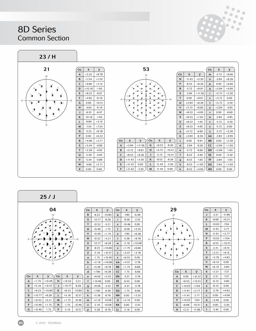
8D SeriesCommon Section
80 © 2013 - SOURIAU
04
+X-X
+Y
-Y
Ctc X Y
A +1.75 +13.49
B +5.16 +12.57
C +8.23 +10.80
D +10.77 +8.28
E +12.52 +5.21
F +13.49 +1.75
G +13.49 -1.75
Ctc X Y
H +12.52 -5.21
J +10.77 -8.28
K +8.23 -10.80
L +5.16 -12.57
M +1.75 -13.49
N -1.75 -13.49
P -5.16 -12.57
Ctc X Y
R -8.23 -10.80
S -10.77 -8.28
T -12.52 -5.21
U -13.49 -1.75
V -13.49 +1.75
W -12.52 +5.21
X -10.77 +8.28
Y -8.23 +10.80
Z -5.16 +12.57
a -1.75 +13.49
b +2.18 +10.08
c +5.38 +8.78
d +7.90 +6.38
e +9.58 +3.35
f +10.46 0.00
g +9.58 -3.35
h +7.90 -6.38
k +5.38 -8.78
m +2.18 -10.08
n -2.18 -10.08
p -5.38 -8.78
Ctc X Y
q -7.90 -6.38
r -9.58 -3.35
s -10.46 0.00
t -9.58 +3.35
u -7.90 +6.38
v -5.38 +8.78
w -2.18 +10.08
x +1.75 +6.66
y +4.37 +3.78
z +6.55 0.00
AA +4.37 -3.78
BB +1.75 -6.66
CC -1.75 -6.66
DD -4.37 -3.78
EE -6.55 0.00
FF -4.37 -3.78
GG -1.75 -6.66
HH 0.00 +3.35
JJ +2.18 0.00
KK 0.00 -3.35
LL -2.18 0.00
29
+X-X
+Y
-Y
Ctc X Y
J -2.31 -11.99
K -6.68 -10.31
L -10.03 -7.04
M -11.91 -2.77
N -11.91 +2.77
P -10.03 +7.04
R -6.55 +10.31
S -2.31 +8.15
T +2.31 +8.15
U +5.79 +4.93
V +8.10 0.00
W +6.10 -4.60
X +2.31 -7.37
Y -2.31 -7.37
Z -6.10 -4.60
a -8.10 0.00
b -5.79 +4.93
c 0.00 +4.09
d +3.40 0.00
e 0.00 -3.30
f -3.40 0.00
Ctc X Y
A 0.00 +12.22
B +6.55 +10.31
C +10.03 +7.04
D +11.91 +2.77
E +11.91 -2.77
F +10.03 -7.04
G +6.68 -10.31
H +2.31 -11.99
25 / J
21
+X-X
+Y
-Y
53
+X-X
+Y
-Y
Ctc X Y
A +3.25 +9.78
B +7.34 +7.24
C +9.80 +3.12
D +10.16 -1.65
E +8.33 -6.07
F +4.65 -9.19
G 0.00 -10.31
H -4.65 -9.19
J -8.33 -6.07
K -10.16 -1.65
L -9.80 +3.12
M -7.34 +7.24
N -3.25 +9.78
P 0.00 +6.22
R +4.06 +3.71
S +5.44 -0.89
T +2.39 -4.93
U -2.39 -4.93
V -5.44 -0.89
W -4.06 +3.71
X 0.00 0.00
Ctc X Y
A +2.84 +11.56
B +5.72 +9.91
C +8.53 +8.26
D +11.43 +3.30
E +11.43 0.00
F +11.43 -3.30
Ctc X Y
G +8.53 -8.26
H +5.72 -10.41
J -5.72 -10.41
K -8.53 -8.26
L -11.43 -3.30
M -11.43 0.00
Ctc X Y
N -11.43 +3.30
P -8.53 +8.26
R -5.72 +9.91
S -2.84 +11.56
T 0.00 +9.91
U +2.84 +8.26
V +5.72 +6.60
W +8.53 +4.95
X +8.53 +1.65
Y +8.53 -1.65
Z +8.53 -4.95
a +5.72 -6.60
b +2.84 -8.26
c 0.00 -9.91
d -2.84 -8.26
e -5.72 -6.60
f -8.53 -4.95
g -8.53 -1.65
h -8.53 +1.65
k -8.53 +4.95
Ctc X Y
m -5.72 +6.60
n -2.84 +8.26
p 0.00 +6.60
q +2.84 +4.95
r +5.72 +3.30
s +5.72 0.00
t +5.72 -3.30
u +2.84 -4.95
v 0.00 -6.60
w -2.84 -4.95
x -5.72 -3.30
y -5.72 0.00
z -5.72 +3.30
AA -2.84 +4.95
BB 0.00 +3.30
CC +2.84 +1.65
DD +2.84 -1.65
EE 0.00 -3.30
FF -2.84 -1.65
GG -2.84 +1.65
HH 0.00 0.00
23 / H
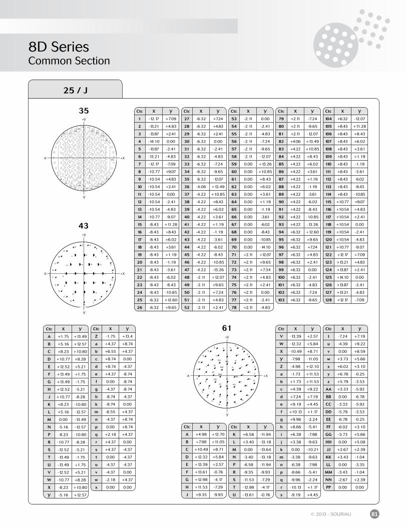
8D SeriesCommon Section
81© 2013 - SOURIAU
43
+X-X
+Y
-Y
+X-X
+Y
-Y
61
Ctc X Y
A +4.98 +12.70
B +7.98 +11.05
C +10.49 +8.71
D +12.32 +5.84
E +13.39 +2.57
F +13.61 -0.76
G +12.98 -4.17
H +11.53 -7.29
J +9.35 -9.93
Ctc X Y
K +6.58 -11.94
L +3.40 -13.18
M 0.00 -13.64
N -3.40 -13.18
P -6.58 -11.94
R -9.35 -9.93
S -11.53 -7.29
T -12.98 -4.17
U -13.61 -0.76
Ctc X Y
V -13.39 +2.57
W -12.32 +5.84
X -10.49 +8.71
Y -7.98 -11.05
Z -4.98 +12.10
a -1.73 +11.53
b +1.73 +11.53
c +4.39 +9.22
d +7.24 +7.19
e +9.19 +4.45
f +10.13 +1.17
g +9.96 -2.24
h +8.66 -5.41
i +6.38 -7.98
j +3.38 -9.63
k 0.00 -10.21
m -3.38 -9.63
n -6.38 -7.98
p -8.66 -5.41
q -9.96 -2.24
r -10.13 +1.17
s -9.19 +4.45
Ctc X Y
t -7.24 +7.19
u -4.39 +9.22
v 0.00 +8.59
w +3.73 +5.66
x +6.02 +3.10
y +6.78 -0.25
z +5.79 -3.53
AA +3.33 -5.92
BB 0.00 -6.78
CC -3.33 -5.92
DD -5.79 -3.53
EE -6.78 -0.25
FF -6.02 +3.10
GG -3.73 +5.66
HH 0.00 +5.08
JJ +2.67 +2.39
KK +3.43 -1.04
LL 0.00 -3.35
MM -3.43 -1.04
NN -2.67 +2.39
PP 0.00 0.00
Ctc X Y
A +1.75 +13.49
B +5.16 +12.57
C +8.23 +10.80
D +10.77 +8.28
E +12.52 +5.21
F +13.49 +1.75
G +13.49 -1.75
H +12.52 -5.21
J +10.77 -8.28
K +8.23 -10.80
L +5.16 -12.57
M 0.00 -13.49
N -5.16 -12.57
P -8.23 -10.80
R -10.77 -8.28
S -12.52 -5.21
T -13.49 -1.75
U -13.49 +1.75
V -12.52 +5.21
W -10.77 +8.28
X -8.23 +10.80
Y -5.16 +12.57
Ctc X Y
Z -1.75 +13.4
a +4.37 +8.74
b +6.55 +4.37
c +8.74 0.00
d +8.74 -4.37
e +4.37 -8.74
f 0.00 -8.74
g -4.37 -8.74
h -8.74 -4.37
k -8.74 0.00
m -6.55 +4.37
n -4.37 +8.74
p 0.00 +8.74
q +2.18 +4.37
r +4.37 0.00
s +4.37 -4.37
t 0.00 -4.37
u -4.37 -4.37
v -4.37 0.00
w -2.18 +4.37
x 0.00 0.00
25 / J
+X-X
+Y
-Y
35 Ctc X Y
1 -12.17 +7.09
2 -13.21 +4.83
3 -13.87 +2.41
4 -14.10 0.00
5 -13.87 -2.41
6 -13.21 -4.83
7 -12.17 -7.09
8 -10.77 +9.07
9 -10.54 +4.83
10 -10.54 +2.41
11 -10.54 0.00
12 -10.54 -2.41
13 -10.54 -4.83
14 -10.77 -9.07
15 -8.43 +11.28
16 -8.43 +8.43
17 -8.43 +6.02
18 -8.43 +3.61
19 -8.43 +1.19
20 -8.43 -1.19
21 -8.43 -3.61
22 -8.43 -6.02
23 -8.43 -8.43
24 -8.43 -10.85
25 -6.32 +12.60
26 -6.32 +9.65
Ctc X Y
27 -6.32 +7.24
28 -6.32 +4.83
29 -6.32 +2.41
30 -6.32 0.00
31 -6.32 -2.41
32 -6.32 -4.83
33 -6.32 -7.24
34 -6.32 -9.65
35 -6.32 -12.07
36 -4.06 +13.49
37 -4.22 +10.85
38 -4.22 +8.43
39 -4.22 +6.02
40 -4.22 +3.61
41 -4.22 +1.19
42 -4.22 -1.19
43 -4.22 -3.61
44 -4.22 -6.02
45 -4.22 -8.43
46 -4.22 -10.85
47 -4.22 -13.26
48 -2.11 +12.07
49 -2.11 +9.65
50 -2.11 +7.24
51 -2.11 +4.83
52 -2.11 +2.41
Ctc X Y
53 -2.11 0.00
54 -2.11 -2.41
55 -2.11 -4.83
56 -2.11 -7.24
57 -2.11 -9.65
58 -2.11 -12.07
59 0.00 +13.26
60 0.00 +10.85
61 0.00 +8.43
62 0.00 +6.02
63 0.00 +3.61
64 0.00 +1.19
65 0.00 -1.19
66 0.00 -3.61
67 0.00 -6.02
68 0.00 -8.43
69 0.00 -10.85
70 0.00 -14.10
71 +2.11 +12.07
72 +2.11 +9.65
73 +2.11 +7.34
74 +2.11 +4.83
75 +2.11 +2.41
76 +2.11 0.00
77 +2.11 -2.41
78 +2.11 -4.83
Ctc X Y
79 +2.11 -7.24
80 +2.11 -9.65
81 +2.11 -12.07
82 +4.06 +13.49
83 +4.22 +10.85
84 +4.22 +8.43
85 +4.22 +6.02
86 +4.22 +3.61
87 +4.22 +1.19
88 +4.22 -1.19
89 +4.22 -3.61
90 +4.22 -6.02
91 +4.22 -8.43
92 +4.22 -10.85
93 +4.22 -13.26
94 +6.32 +12.60
95 +6.32 +9.65
96 +6.32 +7.24
97 +6.32 +4.83
98 +6.32 +2.41
99 +6.32 0.00
100 +6.32 -2.41
101 +6.32 -4.83
102 +6.32 -7.24
103 +6.32 -9.65
Ctc X Y
104 +6.32 -12.07
105 +8.43 +11.28
106 +8.43 +8.43
107 +8.43 +6.02
108 +8.43 +3.61
109 +8.43 +1.19
110 +8.43 -1.19
111 +8.43 -3.61
112 +8.43 -6.02
113 +8.43 -8.43
114 +8.43 -10.85
115 +10.77 +9.07
116 +10.54 +4.83
117 +10.54 +2.41
118 +10.54 0.00
119 +10.54 -2.41
120 +10.54 -4.83
121 +10.77 -9.07
122 +12.17 +7.09
123 +13.21 +4.83
124 +13.87 +2.41
125 +14.10 0.00
126 +13.87 -2.41
127 +13.21 -4.83
128 +12.17 -7.09

8D Series
Derived Series8D Series
Reinforced sealing Series .............................................................................................................
Hermetic Series ...............................................................................................................................
Integrated clinch nuts ....................................................................................................................
Double flange ...................................................................................................................................
PCB contacts without shoulder ...................................................................................................
High density ......................................................................................................................................
Quadrax contacts ............................................................................................................................
Power contacts ................................................................................................................................
High power contacts ......................................................................................................................
BMA coaxial contacts ....................................................................................................................
Optical ELIO® contacts ..................................................................................................................
RJ45/USB Series .............................................................................................................................
84
86
93
96
100
102
104
110
115
120
124
130
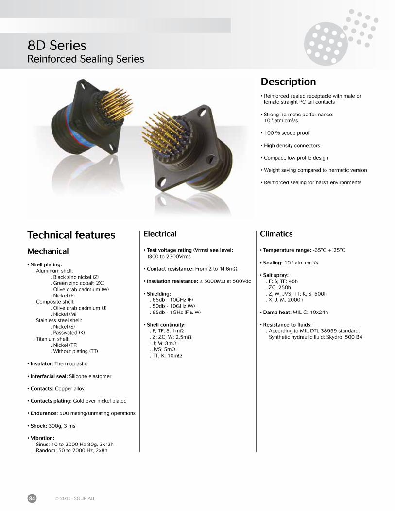
8D SeriesReinforced Sealing Series
84 © 2013 - SOURIAU
Description• Reinforced sealed receptacle with male or female straight PC tail contacts
• Strong hermetic performance: 10-7 atm.cm3/s
• 100 % scoop proof
• High density connectors
• Compact, low profile design
• Weight saving compared to hermetic version
• Reinforced sealing for harsh environments
Technical features
Mechanical
• Shell plating: . Aluminum shell: . Black zinc nickel (Z) . Green zinc cobalt (ZC) . Olive drab cadmium (W) . Nickel (F) . Composite shell: . Olive drab cadmium (J) . Nickel (M) . Stainless steel shell: . Nickel (S) . Passivated (K) . Titanium shell: . Nickel (TF) . Without plating (TT)
• Insulator: Thermoplastic
• Interfacial seal: Silicone elastomer
• Contacts: Copper alloy
• Contacts plating: Gold over nickel plated
• Endurance: 500 mating/unmating operations
• Shock: 300g, 3 ms
• Vibration: . Sinus: 10 to 2000 Hz-30g, 3x12h . Random: 50 to 2000 Hz, 2x8h
Electrical
• Test voltage rating (Vrms) sea level: 1300 to 2300Vrms
• Contact resistance: From 2 to 14.6mΩ
• Insulation resistance: ≥ 5000MΩ at 500Vdc
• Shielding: . 65db - 10GHz (F) . 50db - 10GHz (W) . 85db - 1GHz (F & W)
• Shell continuity: . F; TF; S: 1mΩ . Z; ZC; W: 2.5mΩ . J; M: 3mΩ . JVS: 5mΩ . TT; K: 10mΩ
Climatics
• Temperature range: -65°C +125°C
• Sealing: 10-7 atm.cm3/s
• Salt spray: . F; S; TF: 48h . ZC: 250h . Z; W; JVS; TT; K; S: 500h . X; J; M: 2000h
• Damp heat: MIL C: 10x24h
• Resistance to fluids: . According to MIL-DTL-38999 standard: Synthetic hydraulic fluid: Skydrol 500 B4
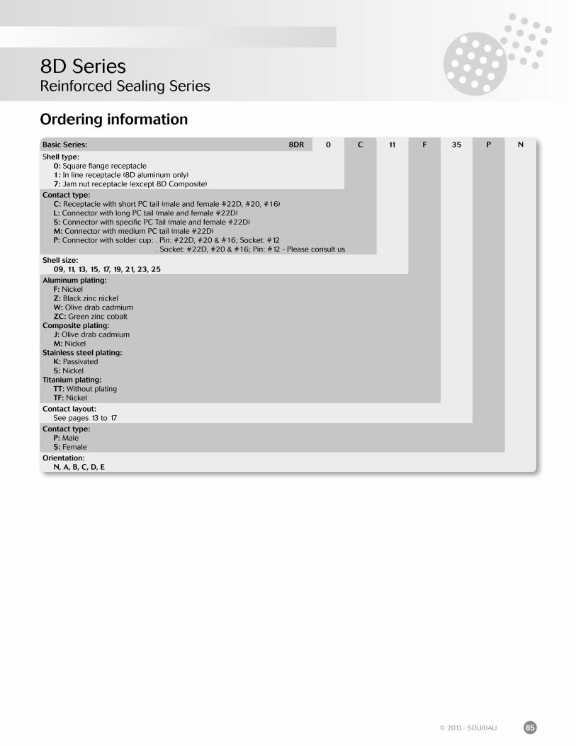
8D SeriesReinforced Sealing Series
85© 2013 - SOURIAU
Ordering information
Basic Series: 8DR 0 C 11 F 35 P N
Shell type: 0: Square flange receptacle 1: In line receptacle (8D aluminum only) 7: Jam nut receptacle (except 8D Composite)
Contact type: C: Receptacle with short PC tail (male and female #22D, #20, #16) L: Connector with long PC tail (male and female #22D) S: Connector with specific PC Tail (male and female #22D) M: Connector with medium PC tail (male #22D) P: Connector with solder cup: . Pin: #22D, #20 & #16; Socket: #12 . Socket: #22D, #20 & #16; Pin: #12 - Please consult us
Shell size: 09, 11, 13, 15, 17, 19, 21, 23, 25Aluminum plating: F: Nickel Z: Black zinc nickel W: Olive drab cadmium ZC: Green zinc cobaltComposite plating: J: Olive drab cadmium M: NickelStainless steel plating: K: Passivated S: NickelTitanium plating: TT: Without plating TF: Nickel
Contact layout: See pages 13 to 17
Contact type: P: Male S: Female
Orientation: N, A, B, C, D, E
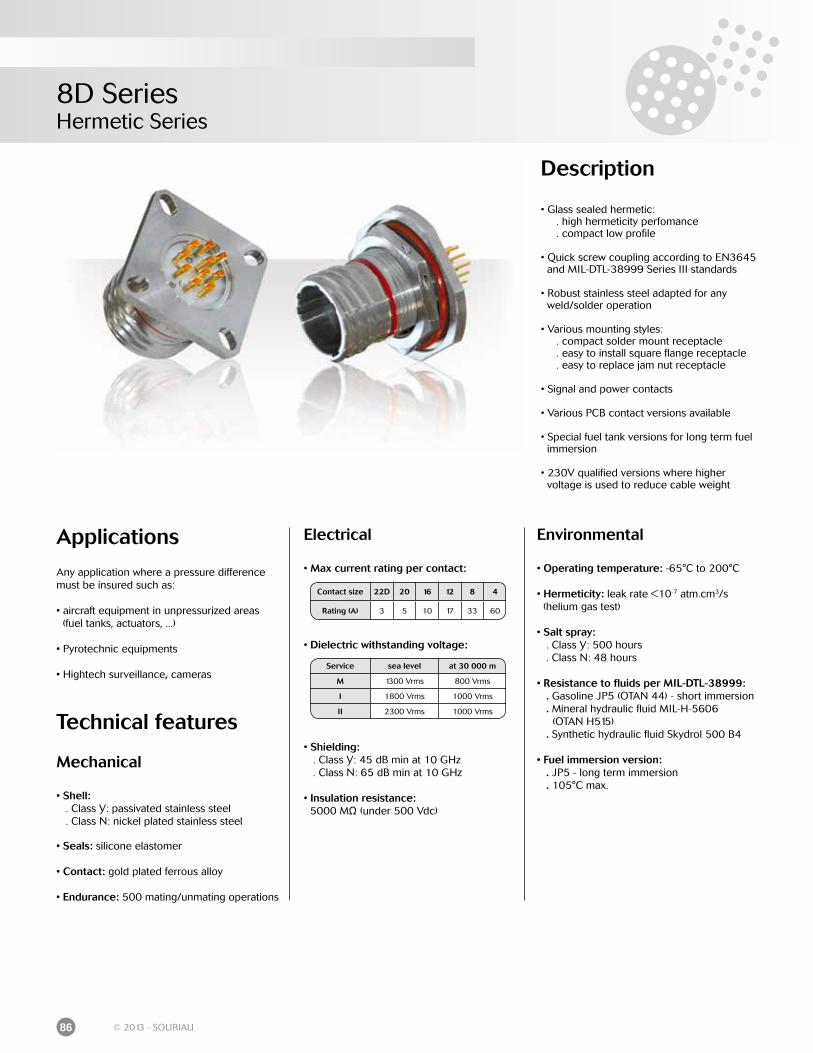
8D SeriesHermetic Series
86 © 2013 - SOURIAU
Applications
Any application where a pressure difference must be insured such as:
• aircraft equipment in unpressurized areas (fuel tanks, actuators, ...)
• Pyrotechnic equipments
• Hightech surveillance, cameras
Technical features
Mechanical
• Shell: . Class Y: passivated stainless steel . Class N: nickel plated stainless steel
• Seals: silicone elastomer
• Contact: gold plated ferrous alloy
• Endurance: 500 mating/unmating operations
Electrical
• Max current rating per contact:
• Dielectric withstanding voltage:
• Shielding: . Class Y: 45 dB min at 10 GHz . Class N: 65 dB min at 10 GHz
• Insulation resistance: 5000 MΩ (under 500 Vdc)
Service sea level at 30 000 m
M 1300 Vrms 800 Vrms
I 1800 Vrms 1000 Vrms
II 2300 Vrms 1000 Vrms
Environmental
• Operating temperature: -65°C to 200°C
• Hermeticity: leak rate <10-7 atm.cm3/s (helium gas test)
• Salt spray: . Class Y: 500 hours . Class N: 48 hours
• Resistance to fluids per MIL-DTL-38999: . Gasoline JP5 (OTAN 44) - short immersion . Mineral hydraulic fluid MIL-H-5606 (OTAN H515) . Synthetic hydraulic fluid Skydrol 500 B4
• Fuel immersion version: . JP5 - long term immersion . 105°C max.
Description
• Glass sealed hermetic: . high hermeticity perfomance . compact low profile
• Quick screw coupling according to EN3645 and MIL-DTL-38999 Series III standards
• Robust stainless steel adapted for any weld/solder operation
• Various mounting styles: . compact solder mount receptacle . easy to install square flange receptacle . easy to replace jam nut receptacle
• Signal and power contacts
• Various PCB contact versions available
• Special fuel tank versions for long term fuel immersion
• 230V qualified versions where higher voltage is used to reduce cable weight
Contact size 22D 20 16 12 8 4
Rating (A) 3 5 10 17 33 60
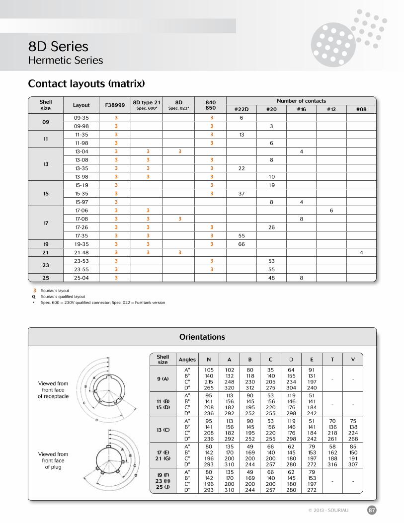
8D SeriesHermetic Series
87© 2013 - SOURIAU
Orientations
Viewed from front faceof plug
Viewed from front face
of receptacle
Shell size Angles N A B C D E T V
9 (A)
A°B°C°D°
105140215265
102132248320
80118230312
35140205275
64155234304
91131197240
- -
11 (B) 15 (D)
A°B°C°D°
95141208236
113156182292
90145195252
53156220255
119146176298
51141184242
- -
13 (C)
A°B°C°D°
95141208236
113156182292
90145195252
53156220255
119146176298
51141184242
70136218261
75138224268
17 (E)21 (G)
A°B°C°D°
80142196293
135170200310
49169200244
66140200257
62145180280
79153197272
58162188316
85150191307
19 (F)23 (H)25 (J)
A°B°C°D°
80142196293
135170200310
49169200244
66140200257
62145180280
79153197272
- -
Contact layouts (matrix)
Shell size
Layout F38999 8D type 21Spec. 600*
8DSpec. 022*
840850
Number of contacts
#22D #20 #16 #12 #08
0909-35 3 3 6
09-98 3 3 3
1111-35 3 3 13
11-98 3 3 6
13
13-04 3 3 3 4
13-08 3 3 3 8
13-35 3 3 3 22
13-98 3 3 3 10
15
15-19 3 3 19
15-35 3 3 37
15-97 3 8 4
17
17-06 3 3 6
17-08 3 3 3 8
17-26 3 3 3 26
17-35 3 3 3 55
19 19-35 3 3 3 66
21 21-48 3 3 3 4
2323-53 3 3 53
23-55 3 3 55
25 25-04 3 48 8
3 Souriau’s layout
Q Souriau’s qualified layout
* Spec. 600 = 230V qualified connector; Spec. 022 = Fuel tank version
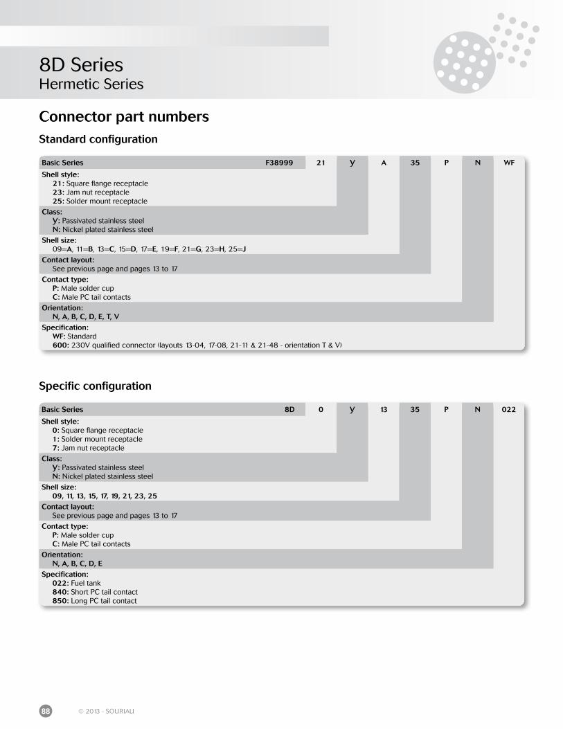
8D SeriesHermetic Series
88 © 2013 - SOURIAU
Basic Series F38999 21 Y A 35 P N WF
Shell style: 21: Square flange receptacle 23: Jam nut receptacle 25: Solder mount receptacle
Class: Y: Passivated stainless steel N: Nickel plated stainless steel
Shell size: 09=A, 11=B, 13=C, 15=D, 17=E, 19=F, 21=G, 23=H, 25=JContact layout: See previous page and pages 13 to 17
Contact type: P: Male solder cup C: Male PC tail contacts
Orientation: N, A, B, C, D, E, T, VSpecification: WF: Standard 600: 230V qualified connector (layouts 13-04, 17-08, 21-11 & 21-48 - orientation T & V)
Connector part numbersStandard configuration
Basic Series 8D 0 Y 13 35 P N 022
Shell style: 0: Square flange receptacle 1: Solder mount receptacle 7: Jam nut receptacle
Class: Y: Passivated stainless steel N: Nickel plated stainless steel
Shell size: 09, 11, 13, 15, 17, 19, 21, 23, 25Contact layout: See previous page and pages 13 to 17
Contact type: P: Male solder cup C: Male PC tail contacts
Orientation: N, A, B, C, D, ESpecification: 022: Fuel tank 840: Short PC tail contact 850: Long PC tail contact
Specific configuration
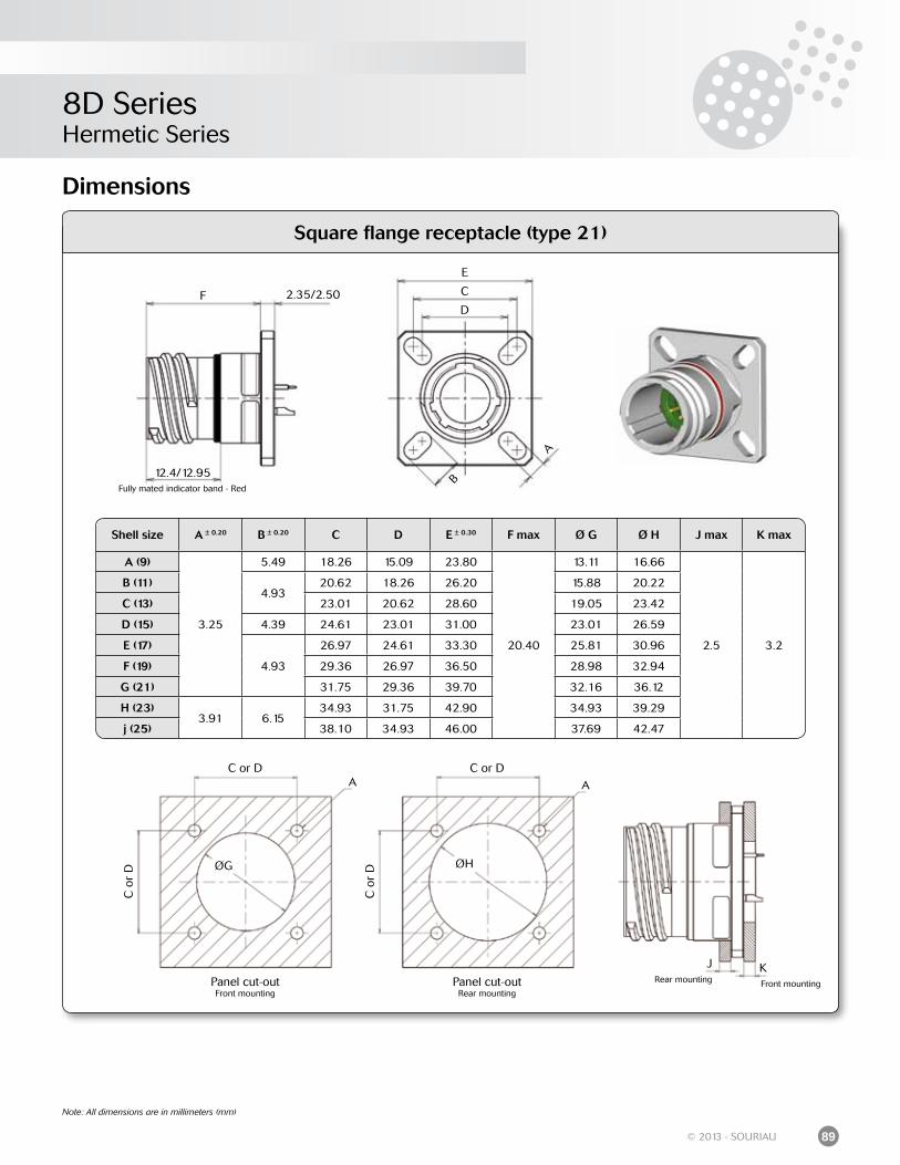
8D SeriesHermetic Series
89© 2013 - SOURIAU
Square flange receptacle (type 21)
Dimensions
Note: All dimensions are in millimeters (mm)
Shell size A ± 0.20 B ± 0.20 C D E ± 0.30 F max Ø G Ø H J max K max
A (9)
3.25
5.49 18.26 15.09 23.80
20.40
13.11 16.66
2.5 3.2
B (11)4.93
20.62 18.26 26.20 15.88 20.22
C (13) 23.01 20.62 28.60 19.05 23.42
D (15) 4.39 24.61 23.01 31.00 23.01 26.59
E (17)
4.93
26.97 24.61 33.30 25.81 30.96
F (19) 29.36 26.97 36.50 28.98 32.94
G (21) 31.75 29.36 39.70 32.16 36.12
H (23)3.91 6.15
34.93 31.75 42.90 34.93 39.29
j (25) 38.10 34.93 46.00 37.69 42.47
A
B
C
D
E
F 2.35/2.50
12.4/12.95Fully mated indicator band - Red
Panel cut-outFront mounting
Panel cut-outRear mounting
A AC or D C or D
C o
r D
C o
r DØG ØH
J KRear mounting Front mounting
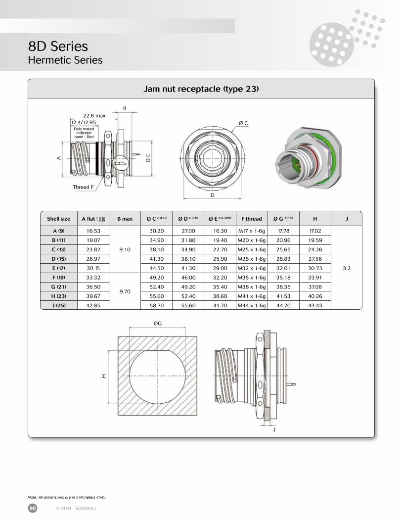
8D SeriesHermetic Series
90 © 2013 - SOURIAU
Jam nut receptacle (type 23)
A Ø E
22.6 maxB
Thread F
12.4/12.95Fully mated
indicator band - Red
D
Ø C
Shell size A flat + 0.10 B max Ø C ± 0.30 Ø D ± 0.40 Ø E ± 0.30/0 F thread Ø G ±0.25 H J
A (9) 16.53
9.10
30.20 27.00 16.30 M17 x 1-6g 17.78 17.02
3.2
B (11) 19.07 34.90 31.80 19.40 M20 x 1-6g 20.96 19.59
C (13) 23.82 38.10 34.90 22.70 M25 x 1-6g 25.65 24.26
D (15) 26.97 41.30 38.10 25.90 M28 x 1-6g 28.83 27.56
E (17) 30.15 44.50 41.30 29.00 M32 x 1-6g 32.01 30.73
F (19) 33.32
9.70
49.20 46.00 32.20 M35 x 1-6g 35.18 33.91
G (21) 36.50 52.40 49.20 35.40 M38 x 1-6g 38.35 37.08
H (23) 39.67 55.60 52.40 38.60 M41 x 1-6g 41.53 40.26
J (25) 42.85 58.70 55.60 41.70 M44 x 1-6g 44.70 43.43
- 0.15
Note: All dimensions are in millimeters (mm)
ØG
H
J
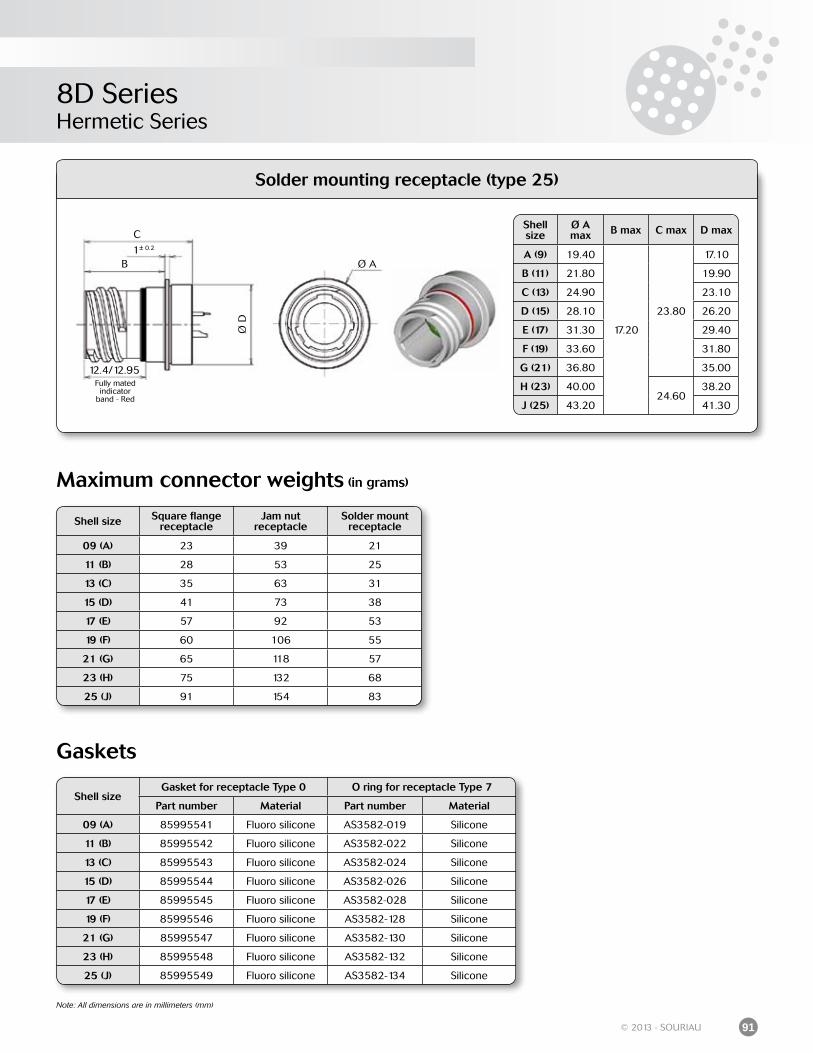
8D SeriesHermetic Series
91© 2013 - SOURIAU
Solder mounting receptacle (type 25)
Note: All dimensions are in millimeters (mm)
Shell size
Ø A max B max C max D max
A (9) 19.40
17.20
23.80
17.10
B (11) 21.80 19.90
C (13) 24.90 23.10
D (15) 28.10 26.20
E (17) 31.30 29.40
F (19) 33.60 31.80
G (21) 36.80 35.00
H (23) 40.0024.60
38.20
J (25) 43.20 41.30
Shell size Square flange receptacle
Jam nutreceptacle
Solder mount receptacle
09 (A) 23 39 21
11 (B) 28 53 25
13 (C) 35 63 31
15 (D) 41 73 38
17 (E) 57 92 53
19 (F) 60 106 55
21 (G) 65 118 57
23 (H) 75 132 68
25 (J) 91 154 83
Maximum connector weights (in grams)
B
C
1± 0.2Ø
D
12.4/12.95Fully mated
indicator band - Red
Ø A
Shell sizeGasket for receptacle Type 0 O ring for receptacle Type 7
Part number Material Part number Material
09 (A) 85995541 Fluoro silicone AS3582-019 Silicone
11 (B) 85995542 Fluoro silicone AS3582-022 Silicone
13 (C) 85995543 Fluoro silicone AS3582-024 Silicone
15 (D) 85995544 Fluoro silicone AS3582-026 Silicone
17 (E) 85995545 Fluoro silicone AS3582-028 Silicone
19 (F) 85995546 Fluoro silicone AS3582-128 Silicone
21 (G) 85995547 Fluoro silicone AS3582-130 Silicone
23 (H) 85995548 Fluoro silicone AS3582-132 Silicone
25 (J) 85995549 Fluoro silicone AS3582-134 Silicone
Gaskets
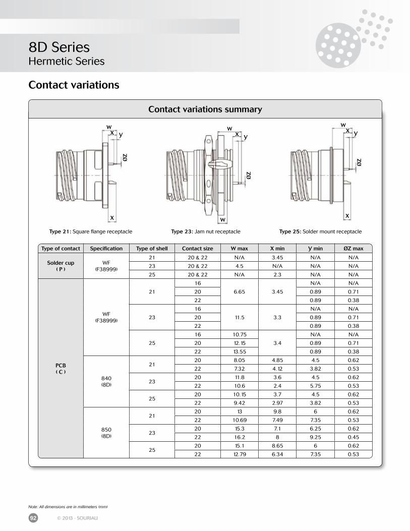
8D SeriesHermetic Series
92 © 2013 - SOURIAU
Contact variations summary
Type 25: Solder mount receptacleType 21: Square flange receptacle Type 23: Jam nut receptacle
Type of contact Specification Type of shell Contact size W max X min Y min ØZ max
Solder cup ( P )
WF(F38999)
21 20 & 22 N/A 3.45 N/A N/A
23 20 & 22 4.5 N/A N/A N/A
25 20 & 22 N/A 2.3 N/A N/A
PCB ( C )
WF(F38999)
21
16
6.65 3.45
N/A N/A
20 0.89 0.71
22 0.89 0.38
23
16
11.5 3.3
N/A N/A
20 0.89 0.71
22 0.89 0.38
25
16 10.75
3.4
N/A N/A
20 12.15 0.89 0.71
22 13.55 0.89 0.38
840(8D)
2120 8.05 4.85 4.5 0.62
22 7.32 4.12 3.82 0.53
2320 11.8 3.6 4.5 0.62
22 10.6 2.4 5.75 0.53
2520 10.15 3.7 4.5 0.62
22 9.42 2.97 3.82 0.53
850(8D)
2120 13 9.8 6 0.62
22 10.69 7.49 7.35 0.53
2320 15.3 7.1 6.25 0.62
22 16.2 8 9.25 0.45
2520 15.1 8.65 6 0.62
22 12.79 6.34 7.35 0.53
Contact variations
X XW
WX Y
ØZ
WX Y
ØZ
WX Y
ØZ
Note: All dimensions are in millimeters (mm)
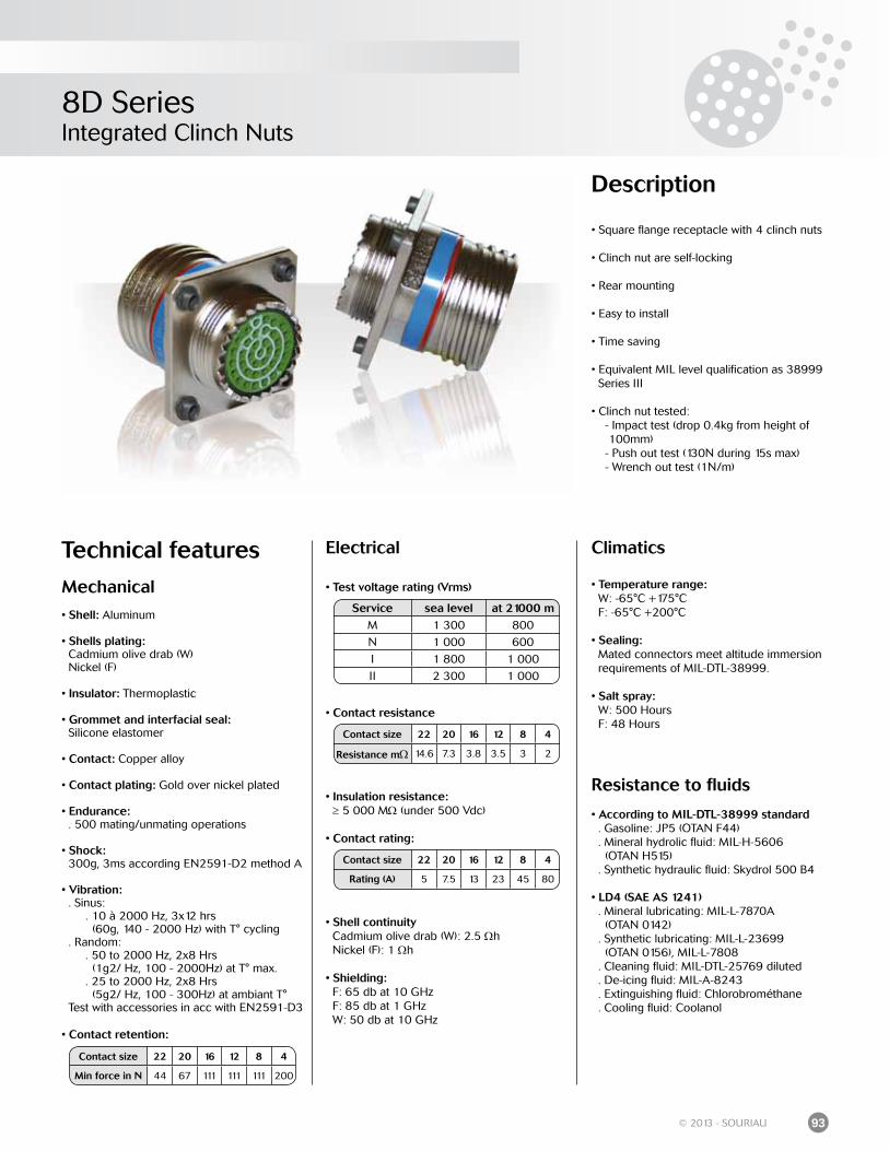
8D SeriesIntegrated Clinch Nuts
93© 2013 - SOURIAU
Description
• Square flange receptacle with 4 clinch nuts
• Clinch nut are self-locking
• Rear mounting
• Easy to install
• Time saving
• Equivalent MIL level qualification as 38999 Series III
• Clinch nut tested: - Impact test (drop 0.4kg from height of 100mm) - Push out test (130N during 15s max) - Wrench out test (1N/m)
Technical features
Mechanical
• Shell: Aluminum
• Shells plating: Cadmium olive drab (W) Nickel (F)
• Insulator: Thermoplastic
• Grommet and interfacial seal: Silicone elastomer
• Contact: Copper alloy
• Contact plating: Gold over nickel plated
• Endurance: . 500 mating/unmating operations
• Shock: 300g, 3ms according EN2591-D2 method A
• Vibration: . Sinus: . 10 à 2000 Hz, 3x12 hrs (60g, 140 - 2000 Hz) with T° cycling . Random: . 50 to 2000 Hz, 2x8 Hrs (1g2/ Hz, 100 - 2000Hz) at T° max. . 25 to 2000 Hz, 2x8 Hrs (5g2/ Hz, 100 - 300Hz) at ambiant T° Test with accessories in acc with EN2591-D3
• Contact retention:
Electrical
• Test voltage rating (Vrms)
• Contact resistance
• Insulation resistance: ≥ 5 000 MΩ (under 500 Vdc)
• Contact rating:
• Shell continuity Cadmium olive drab (W): 2.5 Ωh Nickel (F): 1 Ωh
• Shielding: F: 65 db at 10 GHz F: 85 db at 1 GHz W: 50 db at 10 GHz
Climatics
• Temperature range: W: -65°C +175°C F: -65°C +200°C
• Sealing: Mated connectors meet altitude immersion requirements of MIL-DTL-38999.
• Salt spray: W: 500 Hours F: 48 Hours
Resistance to fluids
• According to MIL-DTL-38999 standard . Gasoline: JP5 (OTAN F44) . Mineral hydrolic fluid: MIL-H-5606 (OTAN H515) . Synthetic hydraulic fluid: Skydrol 500 B4
• LD4 (SAE AS 1241) . Mineral lubricating: MIL-L-7870A (OTAN 0142) . Synthetic lubricating: MIL-L-23699 (OTAN 0156), MIL-L-7808 . Cleaning fluid: MIL-DTL-25769 diluted . De-icing fluid: MIL-A-8243 . Extinguishing fluid: Chlorobrométhane . Cooling fluid: Coolanol
Contact size 22 20 16 12 8 4
Min force in N 44 67 111 111 111 200
Service sea level at 21000 mM 1 300 800
N 1 000 600
I 1 800 1 000
II 2 300 1 000
Contact size 22 20 16 12 8 4
Resistance mΩ 14.6 7.3 3.8 3.5 3 2
Contact size 22 20 16 12 8 4
Rating (A) 5 7.5 13 23 45 80
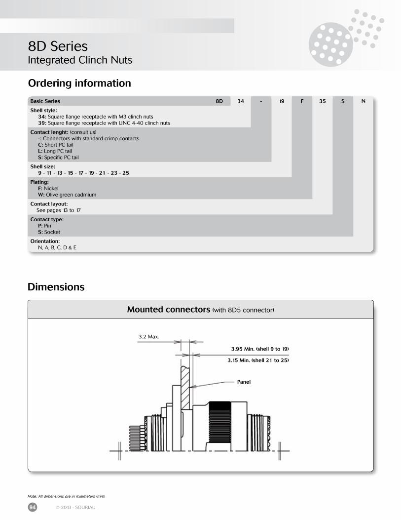
8D SeriesIntegrated Clinch Nuts
94 © 2013 - SOURIAU
Mounted connectors (with 8D5 connector)
Ordering information
3.2 Max.
3.95 Min. (shell 9 to 19)
3.15 Min. (shell 21 to 25)
Panel
Dimensions
Note: All dimensions are in millimeters (mm)
Basic Series 8D 34 - 19 F 35 S N
Shell style: 34: Square flange receptacle with M3 clinch nuts 39: Square flange receptacle with UNC 4-40 clinch nuts
Contact lenght: (consult us) -: Connectors with standard crimp contacts C: Short PC tail L: Long PC tail S: Specific PC tail
Shell size: 9 - 11 - 13 - 15 - 17 - 19 - 21 - 23 - 25
Plating: F: Nickel W: Olive green cadmium
Contact layout: See pages 13 to 17
Contact type: P: Pin S: Socket
Orientation: N, A, B, C, D & E
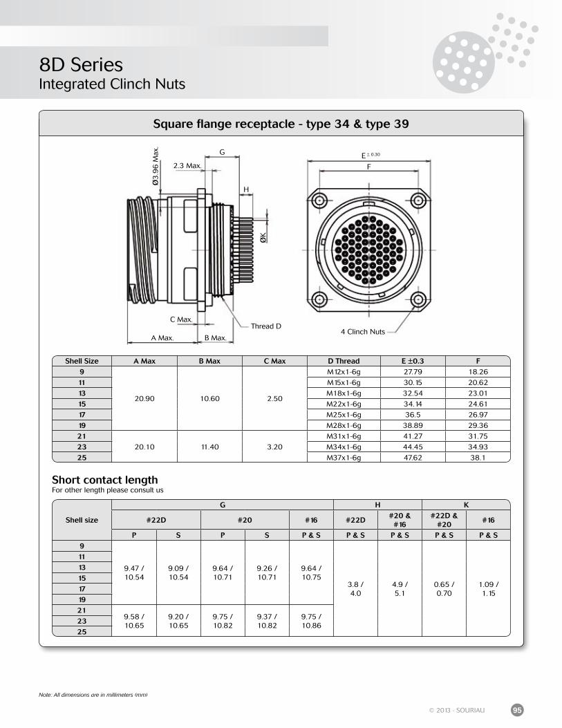
8D SeriesIntegrated Clinch Nuts
95© 2013 - SOURIAU
Note: All dimensions are in millimeters (mm)
Square flange receptacle - type 34 & type 39
E ± 0.30
F
G
2.3 Max.Ø
3.9
6 M
ax.
ØK
H
Thread D
A Max. B Max.
C Max.
4 Clinch Nuts
Shell size
G H K
#22D #20 #16 #22D#20 &
#16#22D &
#20#16
P S P S P & S P & S P & S P & S P & S9
9.47 /10.54
9.09 /10.54
9.64 /10.71
9.26 /10.71
9.64 /10.75
3.8 /4.0
4.9 /5.1
0.65 /0.70
1.09 /1.15
111315171921
9.58 /10.65
9.20 /10.65
9.75 /10.82
9.37 /10.82
9.75 /10.86
2325
Shell Size A Max B Max C Max D Thread E ±0.3 F9
20.90 10.60 2.50
M12x1-6g 27.79 18.26
11 M15x1-6g 30.15 20.62
13 M18x1-6g 32.54 23.01
15 M22x1-6g 34.14 24.61
17 M25x1-6g 36.5 26.97
19 M28x1-6g 38.89 29.36
2120.10 11.40 3.20
M31x1-6g 41.27 31.75
23 M34x1-6g 44.45 34.93
25 M37x1-6g 47.62 38.1
Short contact lengthFor other length please consult us
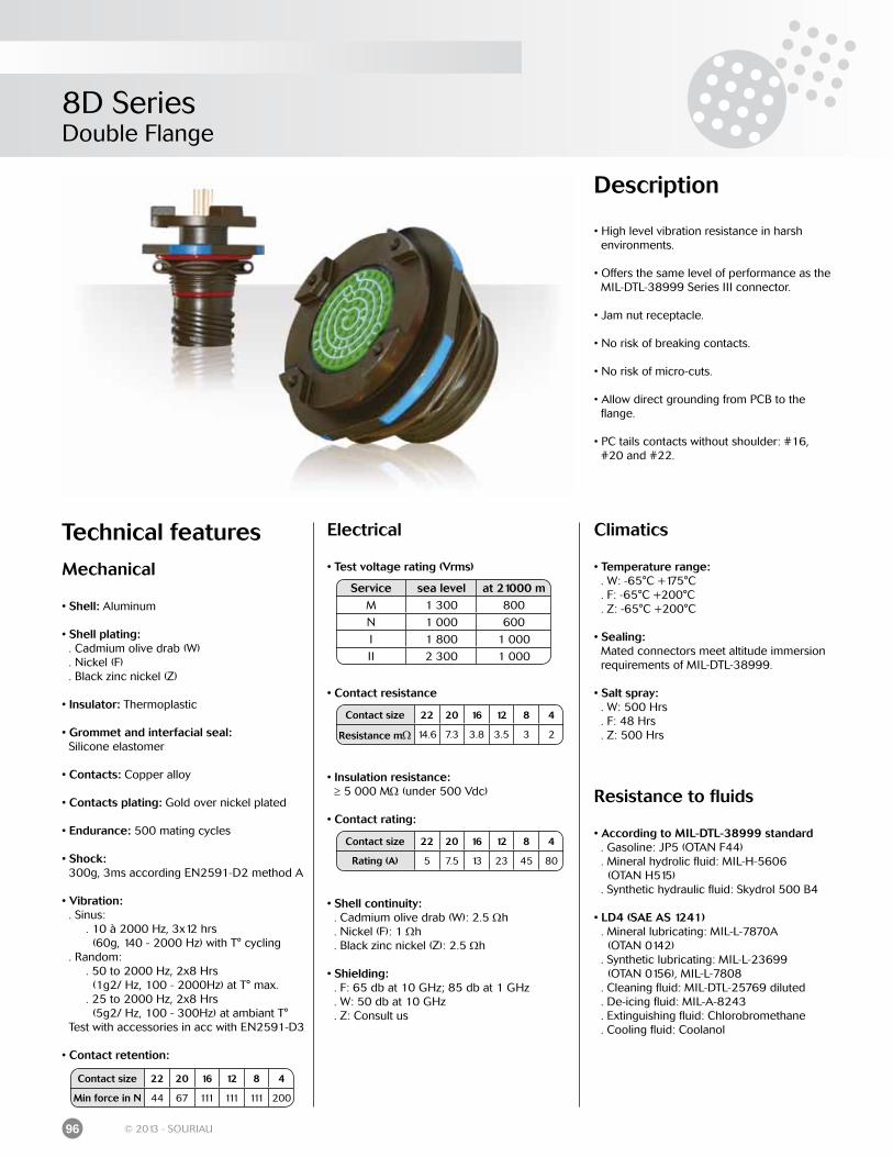
8D SeriesDouble Flange
96 © 2013 - SOURIAU
Technical features
Mechanical
• Shell: Aluminum
• Shell plating: . Cadmium olive drab (W) . Nickel (F) . Black zinc nickel (Z)
• Insulator: Thermoplastic
• Grommet and interfacial seal: Silicone elastomer
• Contacts: Copper alloy
• Contacts plating: Gold over nickel plated
• Endurance: 500 mating cycles
• Shock: 300g, 3ms according EN2591-D2 method A
• Vibration: . Sinus: . 10 à 2000 Hz, 3x12 hrs (60g, 140 - 2000 Hz) with T° cycling . Random: . 50 to 2000 Hz, 2x8 Hrs (1g2/ Hz, 100 - 2000Hz) at T° max. . 25 to 2000 Hz, 2x8 Hrs (5g2/ Hz, 100 - 300Hz) at ambiant T° Test with accessories in acc with EN2591-D3
• Contact retention:
Electrical
• Test voltage rating (Vrms)
• Contact resistance
• Insulation resistance: ≥ 5 000 MΩ (under 500 Vdc)
• Contact rating:
• Shell continuity: . Cadmium olive drab (W): 2.5 Ωh . Nickel (F): 1 Ωh . Black zinc nickel (Z): 2.5 Ωh
• Shielding: . F: 65 db at 10 GHz; 85 db at 1 GHz . W: 50 db at 10 GHz . Z: Consult us
Contact size 22 20 16 12 8 4
Min force in N 44 67 111 111 111 200
Climatics
• Temperature range: . W: -65°C +175°C . F: -65°C +200°C . Z: -65°C +200°C
• Sealing: Mated connectors meet altitude immersion requirements of MIL-DTL-38999.
• Salt spray: . W: 500 Hrs . F: 48 Hrs . Z: 500 Hrs
Resistance to fluids
• According to MIL-DTL-38999 standard . Gasoline: JP5 (OTAN F44) . Mineral hydrolic fluid: MIL-H-5606 (OTAN H515) . Synthetic hydraulic fluid: Skydrol 500 B4
• LD4 (SAE AS 1241) . Mineral lubricating: MIL-L-7870A (OTAN 0142) . Synthetic lubricating: MIL-L-23699 (OTAN 0156), MIL-L-7808 . Cleaning fluid: MIL-DTL-25769 diluted . De-icing fluid: MIL-A-8243 . Extinguishing fluid: Chlorobromethane . Cooling fluid: Coolanol
Service sea level at 21000 mM 1 300 800
N 1 000 600
I 1 800 1 000
II 2 300 1 000
Contact size 22 20 16 12 8 4
Resistance mΩ 14.6 7.3 3.8 3.5 3 2
Contact size 22 20 16 12 8 4
Rating (A) 5 7.5 13 23 45 80
Description
• High level vibration resistance in harsh environments.
• Offers the same level of performance as the MIL-DTL-38999 Series III connector.
• Jam nut receptacle.
• No risk of breaking contacts.
• No risk of micro-cuts.
• Allow direct grounding from PCB to the flange.
• PC tails contacts without shoulder: #16, #20 and #22.
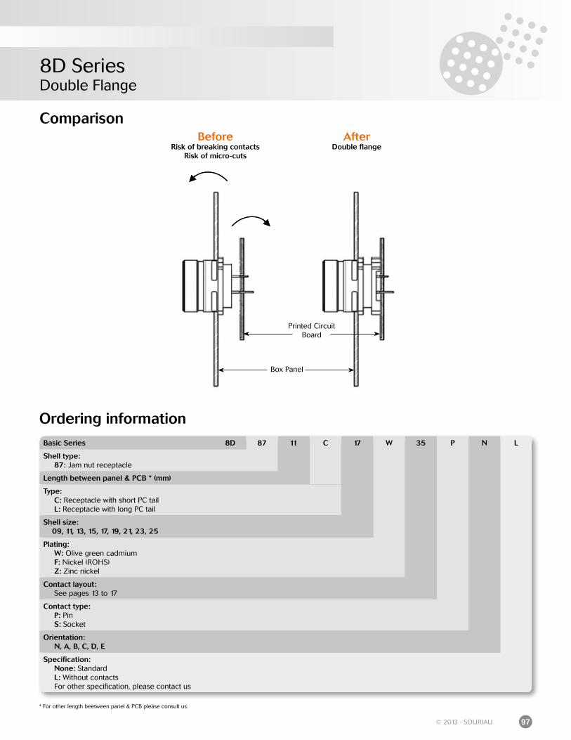
8D SeriesDouble Flange
97© 2013 - SOURIAU
Ordering information
Comparison
Box Panel
Printed Circuit Board
BeforeRisk of breaking contacts
Risk of micro-cuts
AfterDouble flange
Basic Series 8D 87 11 C 17 W 35 P N L
Shell type: 87: Jam nut receptacle
Length between panel & PCB * (mm)
Type: C: Receptacle with short PC tail L: Receptacle with long PC tail
Shell size: 09, 11, 13, 15, 17, 19, 21, 23, 25
Plating: W: Olive green cadmium F: Nickel (ROHS) Z: Zinc nickel
Contact layout: See pages 13 to 17
Contact type: P: Pin S: Socket
Orientation: N, A, B, C, D, E
Specification: None: Standard L: Without contacts For other specification, please contact us
* For other length beetween panel & PCB please consult us.
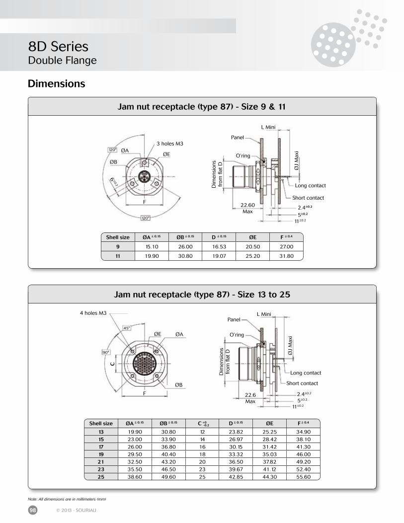
8D SeriesDouble Flange
98 © 2013 - SOURIAU
Jam nut receptacle (type 87) - Size 13 to 25
Jam nut receptacle (type 87) - Size 9 & 11
Dimensions
Shell size ØA ± 0.15 ØB ± 0.15 D ± 0.15 ØE F ± 0.4
9 15.10 26.00 16.53 20.50 27.00
11 19.90 30.80 19.07 25.20 31.80
Shell size ØA ± 0.15 ØB ± 0.15 C +0 D ± 0.15 ØE F ± 0.4
13 19.90 30.80 12 23.82 25.25 34.9015 23.00 33.90 14 26.97 28.42 38.1017 26.00 36.80 16 30.15 31.42 41.3019 29.50 40.40 18 33.32 35.03 46.0021 32.50 43.20 20 36.50 37.82 49.2023 35.50 46.50 23 39.67 41.12 52.4025 38.60 49.60 25 42.85 44.30 55.60
-0.2
3 holes M3120°
120°
ØEØA
ØB
6±0.2
F
Panel
O’ring
L Mini
Long contact
Short contact
2.4±0.2
5±0.2
11±0.2
22.60 Max
ØJ
Max
i
Dim
ensi
ons
from
flat
D
4 holes M3
45°
90°
ØE ØA
ØB
F
Panel
O’ring
L Mini
Long contact
Short contact
2.4±0.2
5±0.2
11±0.2
22.6 Max
ØJ
Max
i
Dim
ensi
ons
from
flat
D
C
Note: All dimensions are in millimeters (mm)
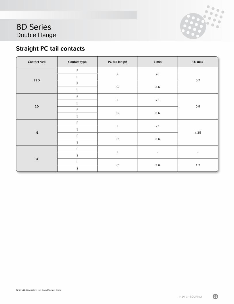
8D SeriesDouble Flange
99© 2013 - SOURIAU
Straight PC tail contacts
Contact size Contact type PC tail length L min ØJ max
22D
PL 7.1
0.7S
PC 3.6
S
20
PL 7.1
0.9S
PC 3.6
S
16
PL 7.1
1.35S
PC 3.6
S
12
PL - -
S
PC 3.6 1.7
S
Note: All dimensions are in millimeters (mm)
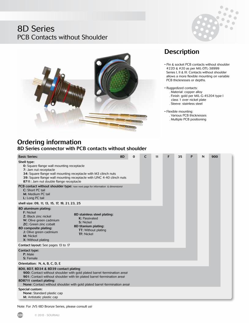
8D SeriesPCB Contacts without Shoulder
100 © 2013 - SOURIAU
Description
• Pin & socket PCB contacts without shoulder #22D & #20 as per MIL-DTL-38999 Series I, II & III. Contacts without shoulder allows a more flexible mounting on variable PCB thicknesses or depths.
• Ruggedized contacts: . Material: copper alloy . Finish: gold per MIL-G-45204 type I class 1 over nickel plate . Sleeve: stainless steel
• Flexible mounting: . Various PCB thicknesses . Multiple PCB positioning
Ordering information8D Series connector with PCB contacts without shoulder
Basic Series: 8D 0 C 11 F 35 P N 900
Shell type: 0: Square flange wall mounting receptacle 7: Jam nut receptacle 34: Square flange wall mounting receptacle with M3 clinch nuts 39: Square flange wall mounting receptacle with UNC 4-40 clinch nuts 8711: Jam nut double flange receptacle
PCB contact without shoulder type: (see next page for information & dimensions)
C: Short PC tail M: Medium PC tail L: Long PC tail
shell size: 09, 11, 13, 15, 17, 19, 21, 23, 25
8D aluminum plating: F: Nickel Z: Black zinc nickel W: Olive green cadmium ZC: Green zinc cobalt8D composite plating: J: Olive green cadmium M: Nickel X: Without plating
Contact layout: See pages 13 to 17
Contact type: P: Male S: Female
Orientation: N, A, B, C, D, E
8D0, 8D7, 8D34 & 8D39 contact plating: 900: Contact without shoulder with gold plated barrel (termination area) 901: Contact without shoulder with tin plated barrel (termination area)8D8711 contact plating: None: Contact without shoulder with gold plated barrel (termination area)
Special custom: None: Standard plastic cap M: Antistatic plastic cap
Note: For JVS (8D Bronze Series, please consult us)
8D stainless steel plating: K: Passivated S: Nickel8D titanium plating: TT: Without plating TF: Nickel
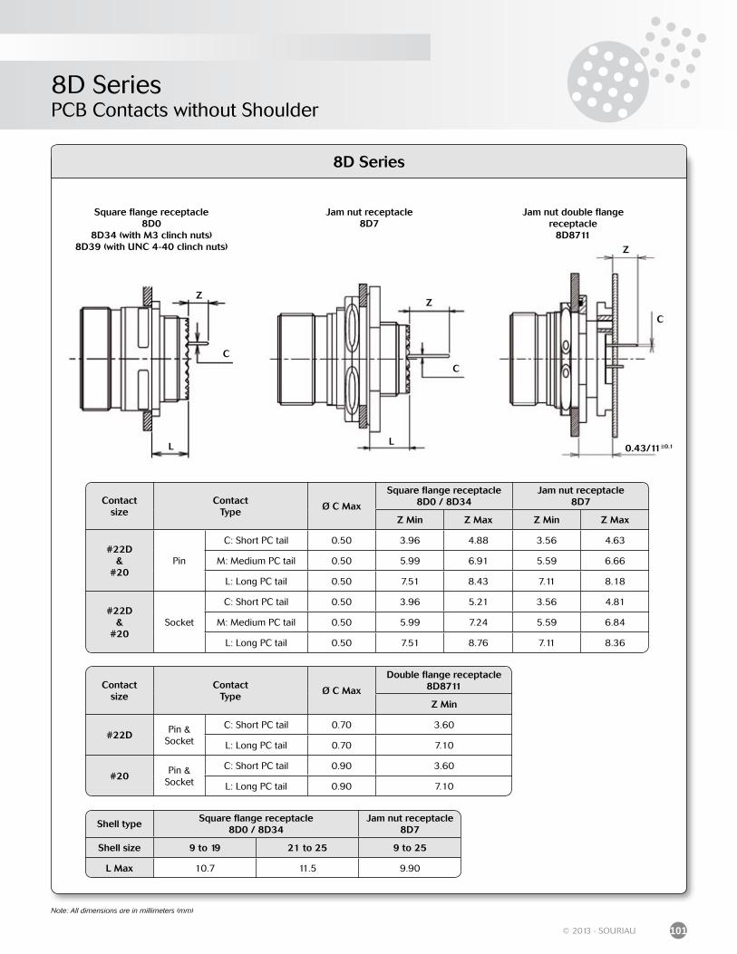
8D SeriesPCB Contacts without Shoulder
101© 2013 - SOURIAU
8D Series
Note: All dimensions are in millimeters (mm)
Z
C
L
Z
C
L
Jam nut receptacle8D7
Jam nut double flange receptacle
8D8711
C
0.43/11±0.1
Z
Shell typeSquare flange receptacle
8D0 / 8D34Jam nut receptacle
8D7
Shell size 9 to 19 21 to 25 9 to 25
L Max 10.7 11.5 9.90
Contactsize
ContactType
Ø C Max
Square flange receptacle8D0 / 8D34
Jam nut receptacle8D7
Z Min Z Max Z Min Z Max
#22D&
#20Pin
C: Short PC tail 0.50 3.96 4.88 3.56 4.63
M: Medium PC tail 0.50 5.99 6.91 5.59 6.66
L: Long PC tail 0.50 7.51 8.43 7.11 8.18
#22D&
#20Socket
C: Short PC tail 0.50 3.96 5.21 3.56 4.81
M: Medium PC tail 0.50 5.99 7.24 5.59 6.84
L: Long PC tail 0.50 7.51 8.76 7.11 8.36
Contactsize
ContactType
Ø C Max
Double flange receptacle 8D8711
Z Min
#22DPin &
Socket
C: Short PC tail 0.70 3.60
L: Long PC tail 0.70 7.10
#20Pin &
Socket
C: Short PC tail 0.90 3.60
L: Long PC tail 0.90 7.10
Square flange receptacle8D0
8D34 (with M3 clinch nuts)8D39 (with UNC 4-40 clinch nuts)
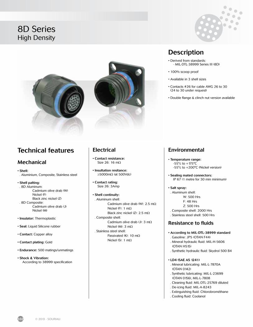
8D SeriesHigh Density
102 © 2013 - SOURIAU
Description• Derived from standards: - MIL-DTL-38999 Series III (8D)
• 100% scoop proof
• Available in 3 shell sizes
• Contacts #26 for cable AWG 26 to 30 (24 to 30 under request)
• Double flange & clinch nut version available
Technical features
Mechanical
• Shell: . Aluminium, Composite, Stainless steel
• Shell palting: . 8D Aluminum: Cadmium olive drab (W) Nickel (F) Black zinc nickel (Z) . 8D Composite: Cadmium olive drab (J) Nickel (M)
• Insulator: Thermoplastic
• Seal: Liquid Silicone rubber
• Contact: Copper alloy
• Contact plating: Gold
• Endurance: 500 matings/unmatings
• Shock & Vibration: According to 38999 specification
Electrical
• Contact resistance: Size 26: 16 mΩ
• Insultation resitance: ≥5000mΩ (at 500Vdc)
• Contact rating: Size 26: 3Amp • Shell continuity: . Aluminum shell: Cadmium olive drab (W): 2.5 mΩ Nickel (F): 1 mΩ Black zinc nickel (Z): 2.5 mΩ . Composite shell: Cadmium olive drab (J): 3 mΩ Nickel (M): 3 mΩ . Stainless steel shell: Passivated (K): 10 mΩ Nickel (S): 1 mΩ
Environmental • Temperature range: -55°c to +175°C -55°c to +200°C (Nickel version)
• Sealing mated connectors: IP 67 (1 metre for 30 min minimum)
• Salt spray: . Aluminum shell: W: 500 Hrs F: 48 Hrs Z: 500 Hrs . Composite shell: 2000 Hrs . Stainless steel shell: 500 Hrs
Resistance to fluids
• According to MIL-DTL-38999 standard . Gasoline: JP5 (OTAN F44) . Mineral hydraulic fluid: MIL-H-5606 (OTAN H515) . Synthetic hydraulic fluid: Skydrol 500 B4
• LD4 (SAE AS 1241) . Mineral lubricating: MIL-L-7870A (OTAN 0142) . Synthetic lubricating: MIL-L-23699 (OTAN 0156), MIL-L-7808 . Cleaning fluid: MIL-DTL-25769 diluted . De-icing fluid: MIL-A-8243 . Extinguishing fluid: Chlorobrométhane . Cooling fluid: Coolanol
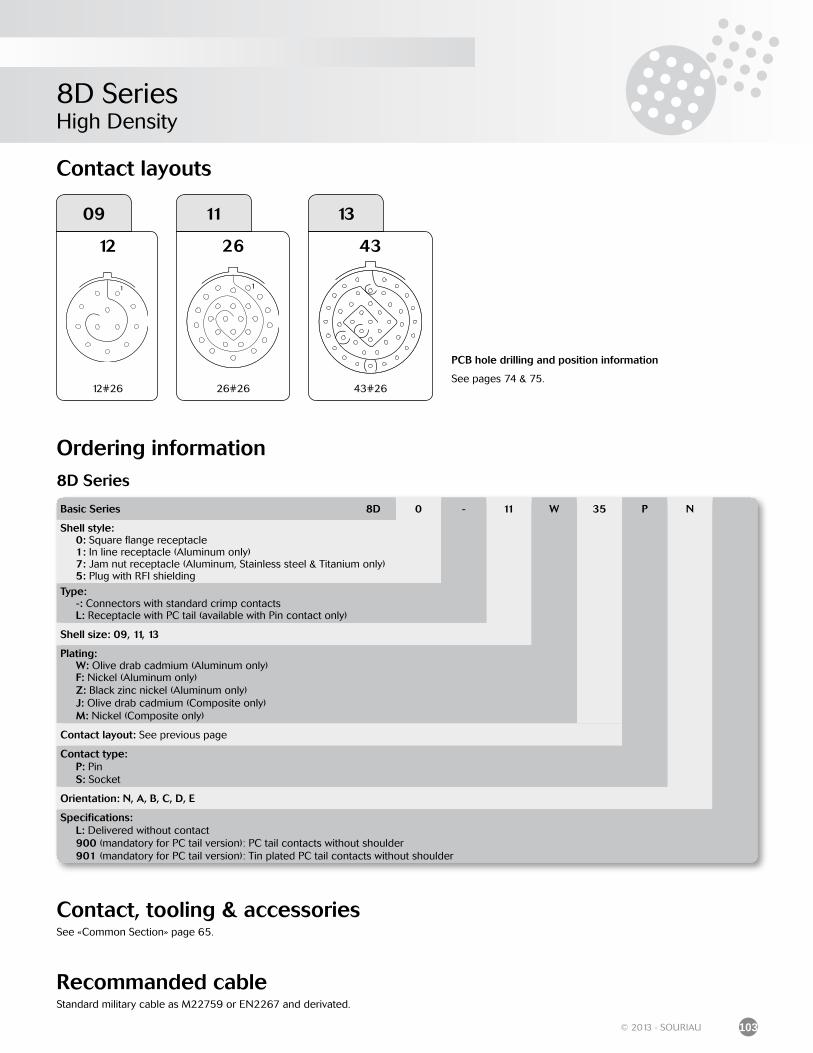
8D SeriesHigh Density
103© 2013 - SOURIAU
Contact layouts
Ordering information
09
12
12#26
11
26
26#26
13
43
43#26
Basic Series 8D 0 - 11 W 35 P N
Shell style: 0: Square flange receptacle 1: In line receptacle (Aluminum only) 7: Jam nut receptacle (Aluminum, Stainless steel & Titanium only) 5: Plug with RFI shielding
Type: -: Connectors with standard crimp contacts L: Receptacle with PC tail (available with Pin contact only)
Shell size: 09, 11, 13
Plating: W: Olive drab cadmium (Aluminum only) F: Nickel (Aluminum only) Z: Black zinc nickel (Aluminum only) J: Olive drab cadmium (Composite only) M: Nickel (Composite only)
Contact layout: See previous page
Contact type: P: Pin S: Socket
Orientation: N, A, B, C, D, E
Specifications: L: Delivered without contact 900 (mandatory for PC tail version): PC tail contacts without shoulder 901 (mandatory for PC tail version): Tin plated PC tail contacts without shoulder
8D Series
Recommanded cableStandard military cable as M22759 or EN2267 and derivated.
Contact, tooling & accessoriesSee «Common Section» page 65.
PCB hole drilling and position information
See pages 74 & 75.
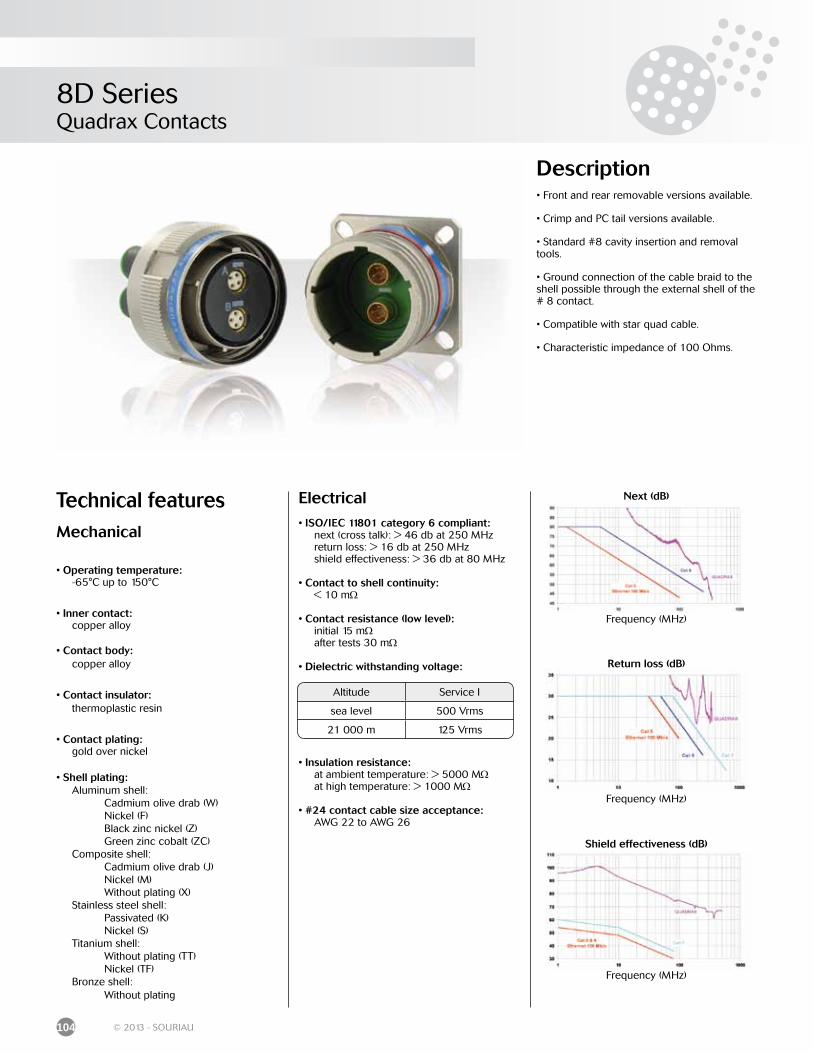
8D SeriesQuadrax Contacts
104 © 2013 - SOURIAU
Electrical• ISO/IEC 11801 category 6 compliant: next (cross talk): > 46 db at 250 MHz return loss: > 16 db at 250 MHz shield effectiveness: > 36 db at 80 MHz
• Contact to shell continuity: < 10 mΩ
• Contact resistance (low level): initial 15 mΩ after tests 30 mΩ
• Dielectric withstanding voltage:
• Insulation resistance: at ambient temperature: > 5000 MΩ at high temperature: > 1000 MΩ
• #24 contact cable size acceptance: AWG 22 to AWG 26
Description• Front and rear removable versions available.
• Crimp and PC tail versions available.
• Standard #8 cavity insertion and removal tools.
• Ground connection of the cable braid to the shell possible through the external shell of the # 8 contact.
• Compatible with star quad cable.
• Characteristic impedance of 100 Ohms.
Technical featuresMechanical
• Operating temperature: -65°C up to 150°C
• Inner contact: copper alloy
• Contact body: copper alloy
• Contact insulator: thermoplastic resin
• Contact plating: gold over nickel
• Shell plating: Aluminum shell: Cadmium olive drab (W) Nickel (F) Black zinc nickel (Z) Green zinc cobalt (ZC) Composite shell: Cadmium olive drab (J) Nickel (M) Without plating (X) Stainless steel shell: Passivated (K) Nickel (S) Titanium shell: Without plating (TT) Nickel (TF) Bronze shell: Without plating
Altitude Service I
sea level 500 Vrms
21 000 m 125 Vrms
Frequency (MHz)
Next (dB)
Frequency (MHz)
Shield effectiveness (dB)
Frequency (MHz)
Return loss (dB)
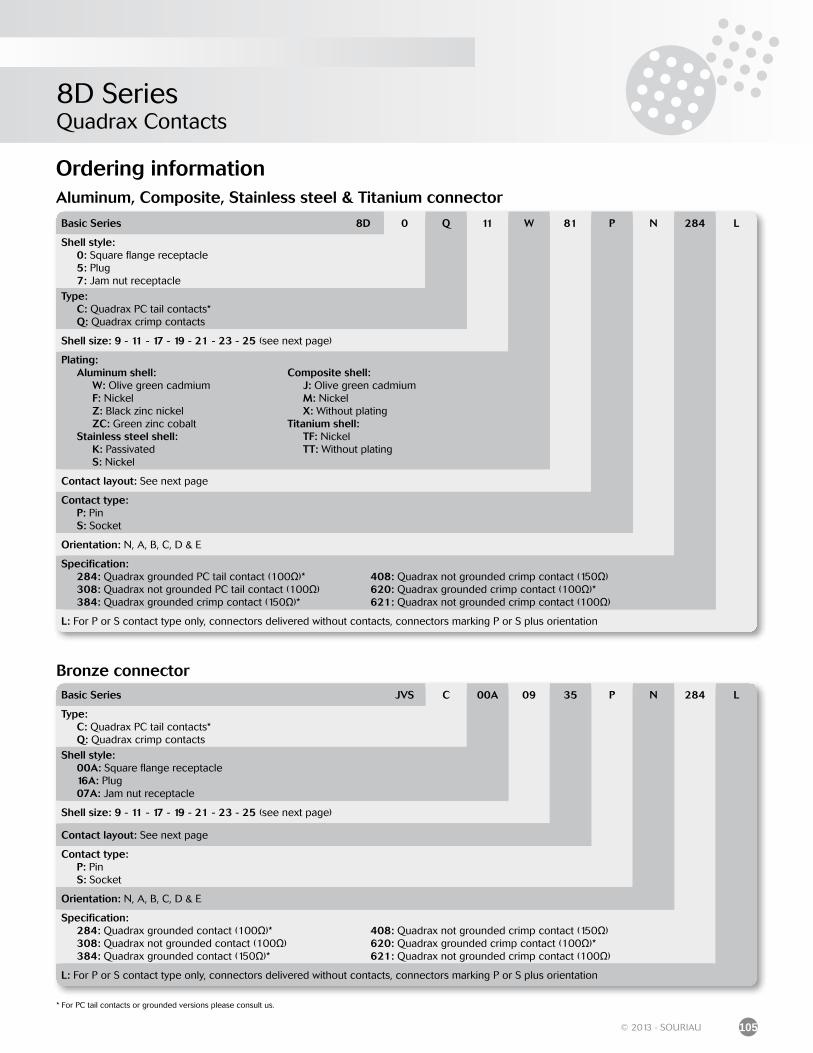
8D SeriesQuadrax Contacts
105© 2013 - SOURIAU
Ordering information
* For PC tail contacts or grounded versions please consult us.
Aluminum, Composite, Stainless steel & Titanium connector
Bronze connector
Basic Series 8D 0 Q 11 W 81 P N 284 L
Shell style: 0: Square flange receptacle 5: Plug 7: Jam nut receptacle
Type: C: Quadrax PC tail contacts* Q: Quadrax crimp contacts
Shell size: 9 - 11 - 17 - 19 - 21 - 23 - 25 (see next page)
Plating: Aluminum shell: W: Olive green cadmium F: Nickel Z: Black zinc nickel ZC: Green zinc cobalt Stainless steel shell: K: Passivated S: Nickel
Composite shell: J: Olive green cadmium M: Nickel X: Without platingTitanium shell: TF: Nickel TT: Without plating
Contact layout: See next page
Contact type: P: Pin S: Socket
Orientation: N, A, B, C, D & E
Specification: 284: Quadrax grounded PC tail contact (100Ω)* 308: Quadrax not grounded PC tail contact (100Ω) 384: Quadrax grounded crimp contact (150Ω)*
408: Quadrax not grounded crimp contact (150Ω)620: Quadrax grounded crimp contact (100Ω)*621: Quadrax not grounded crimp contact (100Ω)
L: For P or S contact type only, connectors delivered without contacts, connectors marking P or S plus orientation
Basic Series JVS C 00A 09 35 P N 284 L
Type: C: Quadrax PC tail contacts* Q: Quadrax crimp contacts
Shell style: 00A: Square flange receptacle 16A: Plug 07A: Jam nut receptacle
Shell size: 9 - 11 - 17 - 19 - 21 - 23 - 25 (see next page)
Contact layout: See next page
Contact type: P: Pin S: Socket
Orientation: N, A, B, C, D & E
Specification: 284: Quadrax grounded contact (100Ω)* 308: Quadrax not grounded contact (100Ω) 384: Quadrax grounded contact (150Ω)*
408: Quadrax not grounded crimp contact (150Ω)620: Quadrax grounded crimp contact (100Ω)*621: Quadrax not grounded crimp contact (100Ω)
L: For P or S contact type only, connectors delivered without contacts, connectors marking P or S plus orientation
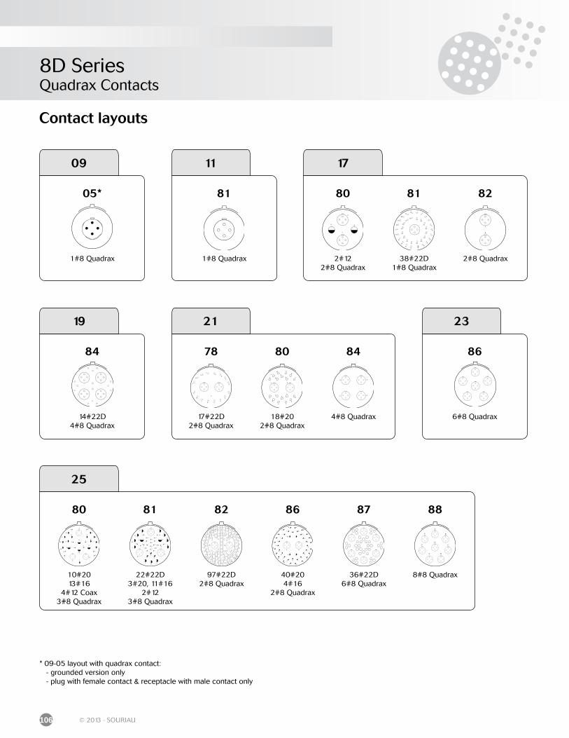
8D SeriesQuadrax Contacts
106 © 2013 - SOURIAU
Contact layouts
05*
1#8 Quadrax
09
81
1#8 Quadrax
11 17
80
2#122#8 Quadrax
81
38#22D1#8 Quadrax
82
2#8 Quadrax
84
14#22D4#8 Quadrax
19 21
78
17#22D2#8 Quadrax
80
18#202#8 Quadrax
84
4#8 Quadrax
25
80
10#20 13#16
4#12 Coax3#8 Quadrax
81
22#22D 3#20, 11#16
2#123#8 Quadrax
82
97#22D2#8 Quadrax
86
40#204#16
2#8 Quadrax
87
36#22D6#8 Quadrax
88
8#8 Quadrax
86
6#8 Quadrax
23
* 09-05 layout with quadrax contact: - grounded version only - plug with female contact & receptacle with male contact only
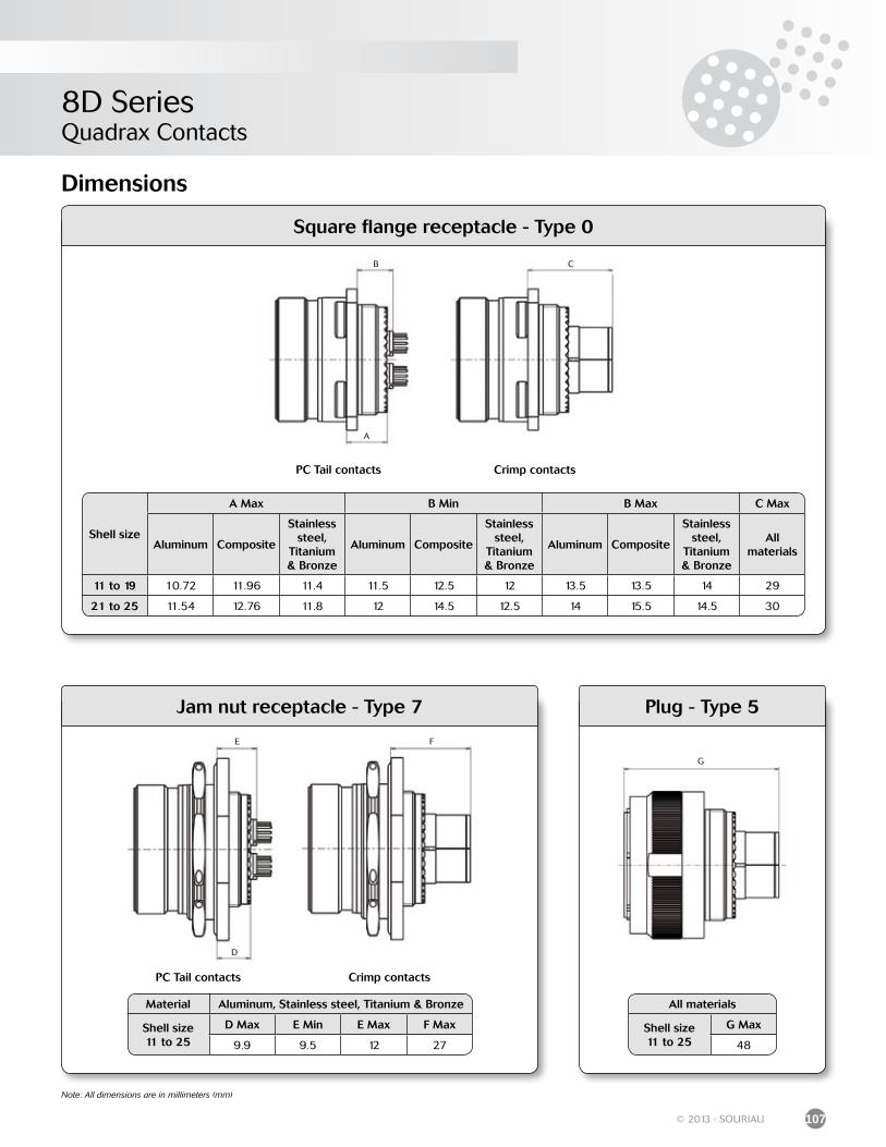
8D SeriesQuadrax Contacts
107© 2013 - SOURIAU
Dimensions
Square flange receptacle - Type 0
Jam nut receptacle - Type 7
Shell size
A Max B Min B Max C Max
Aluminum Composite
Stainless steel,
Titanium & Bronze
Aluminum Composite
Stainless steel,
Titanium & Bronze
Aluminum Composite
Stainless steel,
Titanium & Bronze
Allmaterials
11 to 19 10.72 11.96 11.4 11.5 12.5 12 13.5 13.5 14 29
21 to 25 11.54 12.76 11.8 12 14.5 12.5 14 15.5 14.5 30
Material Aluminum, Stainless steel, Titanium & Bronze
Shell size11 to 25
D Max E Min E Max F Max
9.9 9.5 12 27
D
FE
Note: All dimensions are in millimeters (mm)
A
CB
PC Tail contacts Crimp contacts
PC Tail contacts Crimp contacts
Plug - Type 5
G
All materials
Shell size11 to 25
G Max
48
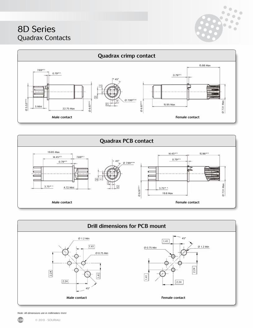
8D SeriesQuadrax Contacts
108 © 2013 - SOURIAU
Note: All dimensions are in millimeters (mm)
Drill dimensions for PCB mount
Male contact
2.24
2.2
4
1.4
1
1.41
45°
Ø 0.75 Min
Ø 1.2 Min
Female contact
2.24
2.2
4
1.4
1
1.4145°
Ø 0.75 Min Ø 1.2 Min
Quadrax crimp contact
Quadrax PCB contact
19.85 Max
14.45±0 5
0.79±0 5
3.75±0 54.72 Mini
7.69±0 2
45°
2
2 1
1
Ø 7.99±0 04
14.45±0 5
0.79±0 5
19.8 Max
Ø 7
.31
Max
3.75±0 5
15.96±0 5
Ø 6
.97
±0
4
22.75 Max
Ø 6
.97
±0
.4
0.79±0 5
Ø 5
.53
±0
02
5 Mini
7.69±0 2
45°
2
2
11 Ø 7.99±0 04
0.79±0 5
15.95 Max
Ø 7
.31
Max
15.88 Max
Ø 6
.97
±0
.4
Male contact Female contact
Male contact Female contact
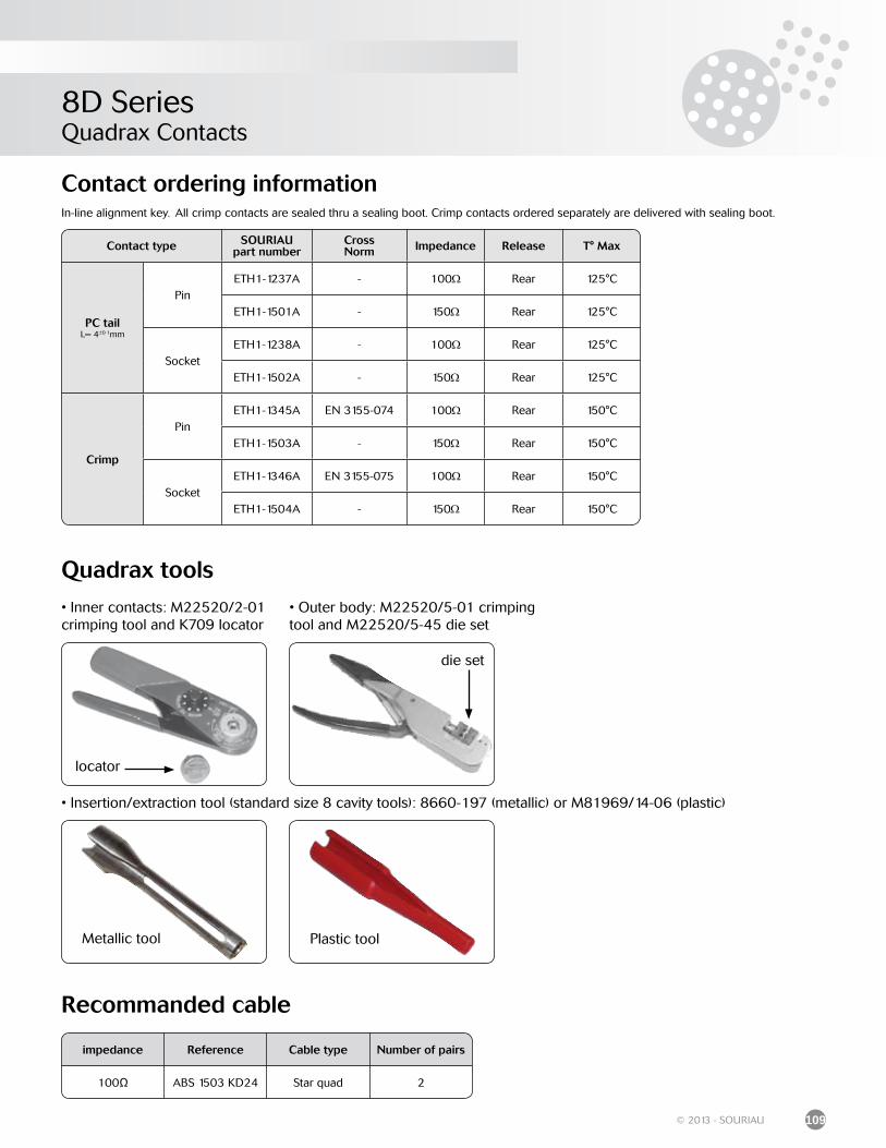
8D SeriesQuadrax Contacts
109© 2013 - SOURIAU
In-line alignment key. All crimp contacts are sealed thru a sealing boot. Crimp contacts ordered separately are delivered with sealing boot.
Contact type SOURIAUpart number
CrossNorm Impedance Release T° Max
PC tailL= 4±0 1mm
PinETH1-1237A - 100Ω Rear 125°C
ETH1-1501A - 150Ω Rear 125°C
SocketETH1-1238A - 100Ω Rear 125°C
ETH1-1502A - 150Ω Rear 125°C
Crimp
PinETH1-1345A EN 3155-074 100Ω Rear 150°C
ETH1-1503A - 150Ω Rear 150°C
SocketETH1-1346A EN 3155-075 100Ω Rear 150°C
ETH1-1504A - 150Ω Rear 150°C
Contact ordering information
Recommanded cable
impedance Reference Cable type Number of pairs
100Ω ABS 1503 KD24 Star quad 2
Quadrax tools
• Insertion/extraction tool (standard size 8 cavity tools): 8660-197 (metallic) or M81969/14-06 (plastic)
Metallic tool Plastic tool
• Outer body: M22520/5-01 crimping tool and M22520/5-45 die set
die set
• Inner contacts: M22520/2-01 crimping tool and K709 locator
locator
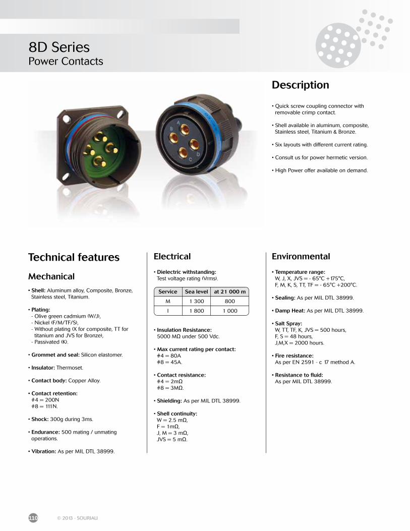
8D SeriesPower Contacts
110 © 2013 - SOURIAU
Description
• Quick screw coupling connector with removable crimp contact.
• Shell available in aluminum, composite, Stainless steel, Titanium & Bronze.
• Six layouts with different current rating.
• Consult us for power hermetic version.
• High Power offer available on demand.
Technical features
Mechanical
• Shell: Aluminum alloy, Composite, Bronze, Stainless steel, Titanium.
• Plating: - Olive green cadmium (W/J), - Nickel (F/M/TF/S), - Without plating (X for composite, TT for titanium and JVS for Bronze), - Passivated (K).
• Grommet and seal: Silicon elastomer.
• Insulator: Thermoset.
• Contact body: Copper Alloy.
• Contact retention: #4 = 200N #8 = 111N.
• Shock: 300g during 3ms.
• Endurance: 500 mating / unmating operations.
• Vibration: As per MIL DTL 38999.
Environmental • Temperature range: W, J, X, JVS = - 65°C +175°C, F, M, K, S, TT, TF = - 65°C +200°C.
• Sealing: As per MIL DTL 38999.
• Damp Heat: As per MIL DTL 38999.
• Salt Spray: W, TT, TF, K, JVS = 500 hours, F, S = 48 hours, J,M,X = 2000 hours.
• Fire resistance: As per EN 2591 - c 17 method A.
• Resistance to fluid: As per MIL DTL 38999.
Electrical
• Dielectric withstanding: Test voltage rating (Vrms).
• Insulation Resistance: 5000 MΩ under 500 Vdc.
• Max current rating per contact: #4 = 80A #8 = 45A.
• Contact resistance: #4 = 2mΩ #8 = 3MΩ.
• Shielding: As per MIL DTL 38999.
• Shell continuity: W = 2.5 mΩ, F = 1mΩ, J, M = 3 mΩ, JVS = 5 mΩ.
Service Sea level at 21 000 m
M 1 300 800
I 1 800 1 000
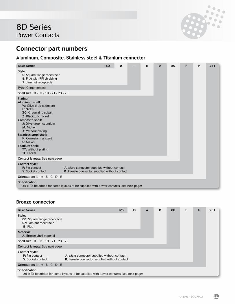
8D SeriesPower Contacts
111© 2013 - SOURIAU
Basic Series 8D 0 - 11 W 80 P N 251
Style: 0: Square flange receptacle 5: Plug with RFI shielding 7: Jam nut receptacle
Type: Crimp contact
Shell size: 11 - 17 - 19 - 21 - 23 - 25
Plating:Aluminum shell: W: Olive drab cadmium F: Nickel ZC: Green zinc cobalt Z: Black zinc nickelComposite shell: J: Olive green cadmium M: Nickel X: Without platingStainless steel shell: K: Corrosion resistant S: NickelTitanium shell: TT: Without plating TF: Nickel
Contact layouts: See next page
Contact style: P: Pin contact A: Male connector supplied without contact S: Socket contact B: Female connector supplied without contact
Orientation: N - A - B - C - D - E
Specification: 251: To be added for some layouts to be supplied with power contacts (see next page)
Basic Series JVS 16 A 11 80 P N 251
Style: 00: Square flange receptacle 07: Jam nut receptacle 16: Plug
Material: A: Bronze shell material
Shell size: 11 - 17 - 19 - 21 - 23 - 25
Contact layouts: See next page
Contact style: P: Pin contact A: Male connector supplied without contact S: Socket contact B: Female connector supplied without contact
Orientation: N - A - B - C - D - E
Specification: 251: To be added for some layouts to be supplied with power contacts (see next page)
Aluminum, Composite, Stainless steel & Titanium connector
Bronze connector
Connector part numbers
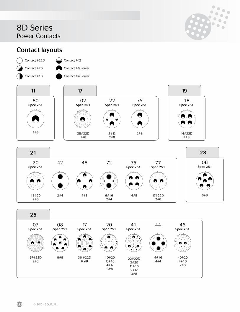
8D SeriesPower Contacts
112 © 2013 - SOURIAU
Contact layouts
42
20Spec 251
41Spec 251
07Spec 251
08Spec 251
17Spec 251
44 46Spec 251
25
48 72 75Spec 251
77Spec 251
11
80Spec 251
1#8
02Spec 251
22Spec 251
75Spec 251
17
38#22D1#8
2#122#8
2#8
18Spec 251
19
14#22D4#8
20Spec 251
21
18#202#8
2#4 4#8
06Spec 251
23
6#86#162#4
4#8 17#22D2#8
97#22D2#8
8#8 36 #22D6 #8
10#20 13#164#12 3#8
22#22D 3#2011#16 2#123#8
4#164#4
40#20 4#162#8
Contact #22D
Contact #20
Contact #16
Contact #12
Contact #8 Power
Contact #4 Power
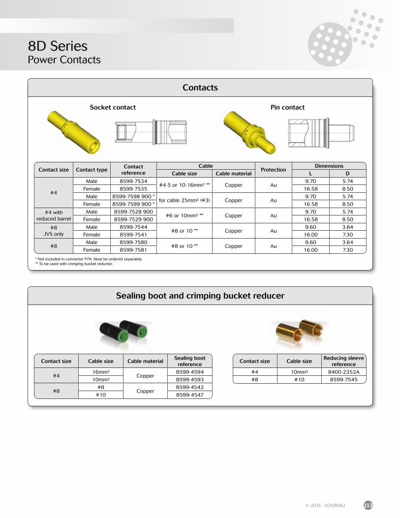
8D SeriesPower Contacts
113© 2013 - SOURIAU
Contacts
* Not included in connector P/N. Must be ordered separately.** To be used with crimping bucket reductor.
Socket contact Pin contact
Sealing boot and crimping bucket reducer
Contact size Contact typeContact
referenceCable
ProtectionDimensions
Cable size Cable material L D
#4
Male 8599-7534#4-5 or 10-16mm² ** Copper Au
9.70 5.74
Female 8599-7535 16.58 8.50
Male 8599-7598 900 *for cable 25mm² (#3) Copper Au
9.70 5.74
Female 8599-7599 900 * 16.58 8.50
#4 withreduced barrel
Male 8599-7528 900#6 or 10mm² ** Copper Au
9.70 5.74
Female 8599-7529 900 16.58 8.50
#8JVS only
Male 8599-7544#8 or 10 ** Copper Au
9.60 3.64
Female 8599-7541 16.00 7.30
#8Male 8599-7580
#8 or 10 ** Copper Au9.60 3.64
Female 8599-7581 16.00 7.30
Contact size Cable size Cable materialSealing boot
reference
#416mm²
Copper8599-4594
10mm² 8599-4593
#8#8
Copper8599-4542
#10 8599-4547
Contact size Cable sizeReducing sleeve
reference#4 10mm² 8400-2352A
#8 #10 8599-7545
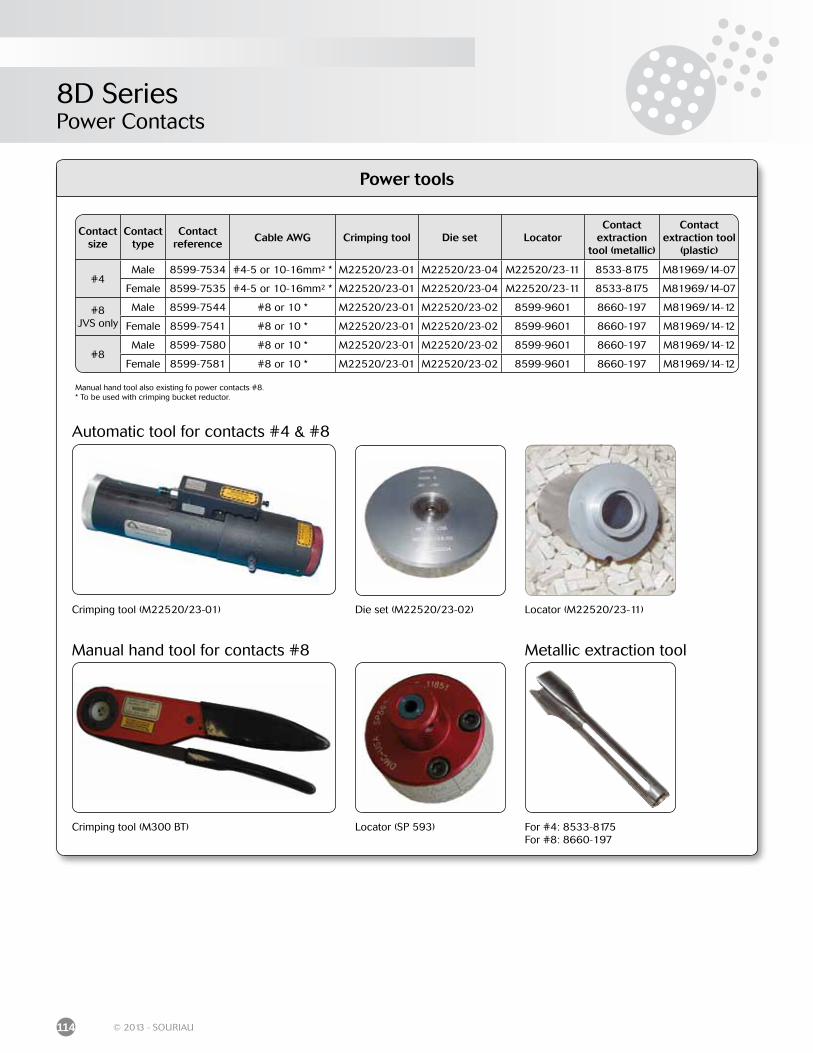
8D SeriesPower Contacts
114 © 2013 - SOURIAU
Power tools
Automatic tool for contacts #4 & #8
Manual hand tool for contacts #8 Metallic extraction tool
Contactsize
Contacttype
Contactreference
Cable AWG Crimping tool Die set LocatorContact
extractiontool (metallic)
Contactextraction tool
(plastic)
#4Male 8599-7534 #4-5 or 10-16mm² * M22520/23-01 M22520/23-04 M22520/23-11 8533-8175 M81969/14-07
Female 8599-7535 #4-5 or 10-16mm² * M22520/23-01 M22520/23-04 M22520/23-11 8533-8175 M81969/14-07
#8JVS only
Male 8599-7544 #8 or 10 * M22520/23-01 M22520/23-02 8599-9601 8660-197 M81969/14-12
Female 8599-7541 #8 or 10 * M22520/23-01 M22520/23-02 8599-9601 8660-197 M81969/14-12
#8Male 8599-7580 #8 or 10 * M22520/23-01 M22520/23-02 8599-9601 8660-197 M81969/14-12
Female 8599-7581 #8 or 10 * M22520/23-01 M22520/23-02 8599-9601 8660-197 M81969/14-12
Crimping tool (M22520/23-01) Die set (M22520/23-02) Locator (M22520/23-11)
Crimping tool (M300 BT) Locator (SP 593) For #4: 8533-8175For #8: 8660-197
Manual hand tool also existing fo power contacts #8.* To be used with crimping bucket reductor.
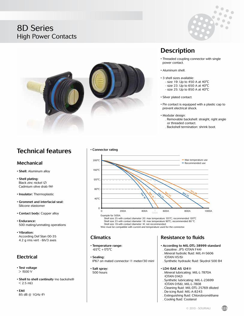
8D SeriesHigh Power Contacts
115© 2013 - SOURIAU
• Connector rating
Example for 500A: Shell size 25 with contact diameter 20: max temperature 135°C; recommended 120°C Shell size 23 with contact diameter 18: max temperature 90°C; recommended 80 °C Shell size 19 with contact diameter 14: not recommended Wire must be compatible with current and temperature used for the connector.
200°C
160°C
120°C
80°C
40°C
00 200A 400A 600A 800A 1000A
500A
Size 23
Size 23
Size 19
Size 19
Size 25
Size 25
- Max temperature use
- Recommended use
Description• Threaded coupling connector with single power contact.
• Aluminum shell.
• 3 shell sizes available: - size 19: Up to 450 A at 40°C - size 23: Up to 650 A at 40°C - size 25: Up to 850 A at 40°C
• Silver plated contact.
• Pin contact is equipped with a plastic cap to prevent electrical shock.
• Modular design: . Removable backshell: straight, right angle or threaded contact. . Backshell termination: shrink boot.
Technical features
Mechanical
• Shell: Aluminum alloy
• Shell plating: Black zinc nickel (Z) Cadmium olive drab (W)
• Insulator: Thermoplastic
• Grommet and interfacial seal: Silicone elastomer
• Contact body: Copper alloy
• Endurance: 500 mating/unmating operations
• Vibration: According Def Stan 00-35 4.2 g rms vert - 6h/3 axes
Electrical
• Test voltage > 1500 V
• Shell to shell continuity (no backshell) < 2.5 mΩ
• EMI 85 dB @ 1GHz (F)
Resistance to fluids
• According to MIL-DTL-38999 standard . Gasoline: JP5 (OTAN F44) . Mineral hydrolic fluid: MIL-H-5606 (OTAN H515) . Synthetic hydraulic fluid: Skydrol 500 B4
• LD4 (SAE AS 1241) . Mineral lubricating: MIL-L-7870A (OTAN 0142) . Synthetic lubricating: MIL-L-23699 (OTAN 0156), MIL-L-7808 . Cleaning fluid: MIL-DTL-25769 diluted . De-icing fluid: MIL-A-8243 . Extinguishing fluid: Chlorobrométhane . Cooling fluid: Coolanol
Climatics
• Temperature range: -65°C +175°C
• Sealing: IP67 on mated connector (1 meter/30 min)
• Salt spray: 500 hours
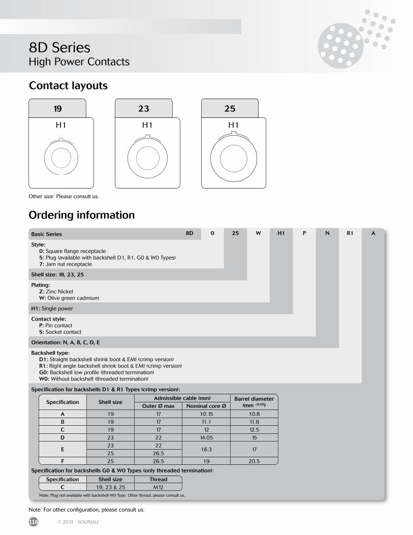
8D SeriesHigh Power Contacts
116 © 2013 - SOURIAU
Contact layouts
H1
19
H1
23
H1
25
Other size: Please consult us.
Basic Series 8D 0 25 W H1 P N R1 A
Style: 0: Square flange receptacle 5: Plug (available with backshell D1, R1, G0 & W0 Types) 7: Jam nut receptacle
Shell size: 19, 23, 25
Plating: Z: Zinc Nickel W: Olive green cadmium
H1: Single power
Contact style: P: Pin contact S: Socket contact
Orientation: N, A, B, C, D, E
Backshell type: D1: Straight backshell shrink boot & EMI (crimp version) R1: Right angle backshell shrink boot & EMI (crimp version) G0: Backshell low profile (threaded termination) W0: Without backshell (threaded termination)
Specification for backshells D1 & R1 Types (crimp version):
Specification for backshells G0 & W0 Types (only threaded termination):
Note: Plug not available with backshell W0 Type. Other thread, please consult us.
Ordering information
Note: For other configuration, please consult us.
Specification Shell size ThreadC 19, 23 & 25 M12
Specification Shell sizeAdmissible cable (mm) Barrel diameter
(mm ±0.05)Outer Ø max Nominal core ØA 19 17 10.15 10.8
B 19 17 11.1 11.8
C 19 17 12 12.5
D 23 22 14.05 15
E23 22
16.3 1725 26.5
F 25 26.5 19 20.5
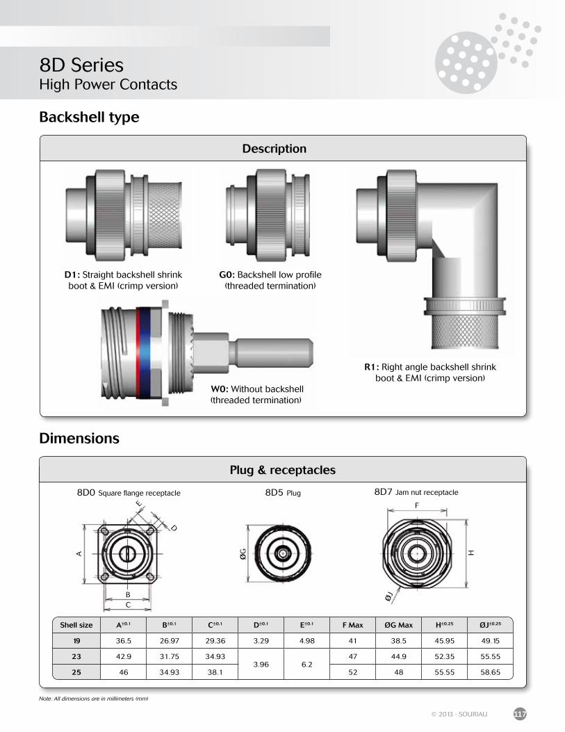
8D SeriesHigh Power Contacts
117© 2013 - SOURIAU
Description
D1: Straight backshell shrink boot & EMI (crimp version)
R1: Right angle backshell shrink boot & EMI (crimp version)
Backshell type
G0: Backshell low profile (threaded termination)
Dimensions
Plug & receptacles
8D5 Plug 8D7 Jam nut receptacle
ØG
F
H
ØJ
CB
E
D
A
8D0 Square flange receptacle
Shell size A±0.1 B±0.1 C±0.1 D±0.1 E±0.1 F Max ØG Max H±0.25 ØJ±0.25
19 36.5 26.97 29.36 3.29 4.98 41 38.5 45.95 49.15
23 42.9 31.75 34.933.96 6.2
47 44.9 52.35 55.55
25 46 34.93 38.1 52 48 55.55 58.65
W0: Without backshell (threaded termination)
Note: All dimensions are in millimeters (mm)
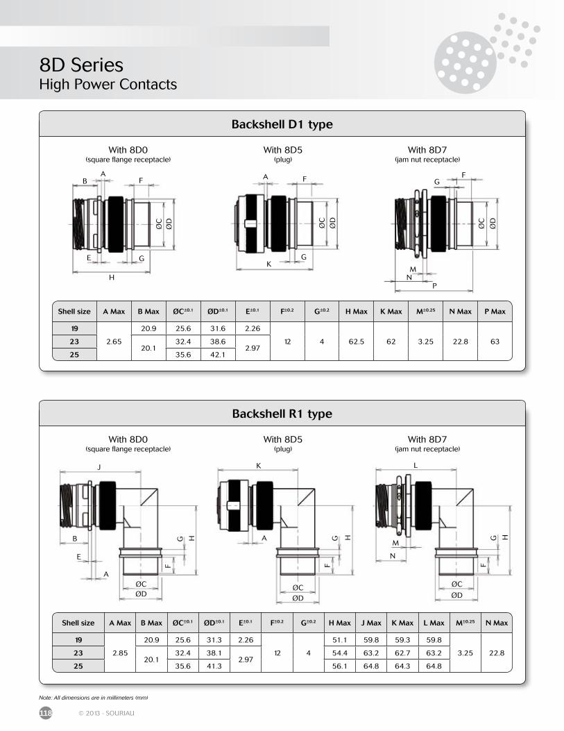
8D SeriesHigh Power Contacts
118 © 2013 - SOURIAU
Note: All dimensions are in millimeters (mm)
Backshell D1 type
Shell size A Max B Max ØC±0.1 ØD±0.1 E±0.1 F±0.2 G±0.2 H Max K Max M±0.25 N Max P Max
19
2.65
20.9 25.6 31.6 2.26
12 4 62.5 62 3.25 22.8 632320.1
32.4 38.62.97
25 35.6 42.1
G
F
ØC
ØD
B
H
G
F
K
GF
M
PN
ØC
ØD
ØC
ØD
A A
E
With 8D5(plug)
With 8D0(square flange receptacle)
With 8D7(jam nut receptacle)
Backshell R1 type
A
B
ØCØD
F
J
G H
FG H
FG H
ØCØD
ØC
ØD
K L
M
N
A
E
With 8D5(plug)
With 8D0(square flange receptacle)
With 8D7(jam nut receptacle)
Shell size A Max B Max ØC±0.1 ØD±0.1 E±0.1 F±0.2 G±0.2 H Max J Max K Max L Max M±0.25 N Max
19
2.85
20.9 25.6 31.3 2.26
12 4
51.1 59.8 59.3 59.8
3.25 22.82320.1
32.4 38.12.97
54.4 63.2 62.7 63.2
25 35.6 41.3 56.1 64.8 64.3 64.8

8D SeriesHigh Power Contacts
119© 2013 - SOURIAU
Note: All dimensions are in millimeters (mm)
Backshell G0 type
Shell size A Max B Max C Max D Max E±0.1 F±0.2 ØG±0.1 H Max J Max K Max L Max M±0.25
19
2.65
20.9 29
39.4
2.26
25
31.3
88.1M12 x 1.75
22.6
27.6
3.252320.1 29.8 2.97
38.128.4
25 41.3
With 8D5(plug)
With 8D0(square flange receptacle)
With 8D7(jam nut receptacle)
J
F
DH
A
G J
F
DK L
M
G
B C D
E F
JA
G
Backshell W0 type
With 8D0(square flange receptacle)
With 8D7(jam nut receptacle)
B C D
E F
J J
F
DK L
M
Shell size B Max C Max D Max E±0.1 F±0.2 J Max K Max L Max M±0.25
19 20.9
14 40
2.26
25 M12 x 1.75 22.6 12 3.252320.1 2.97
25
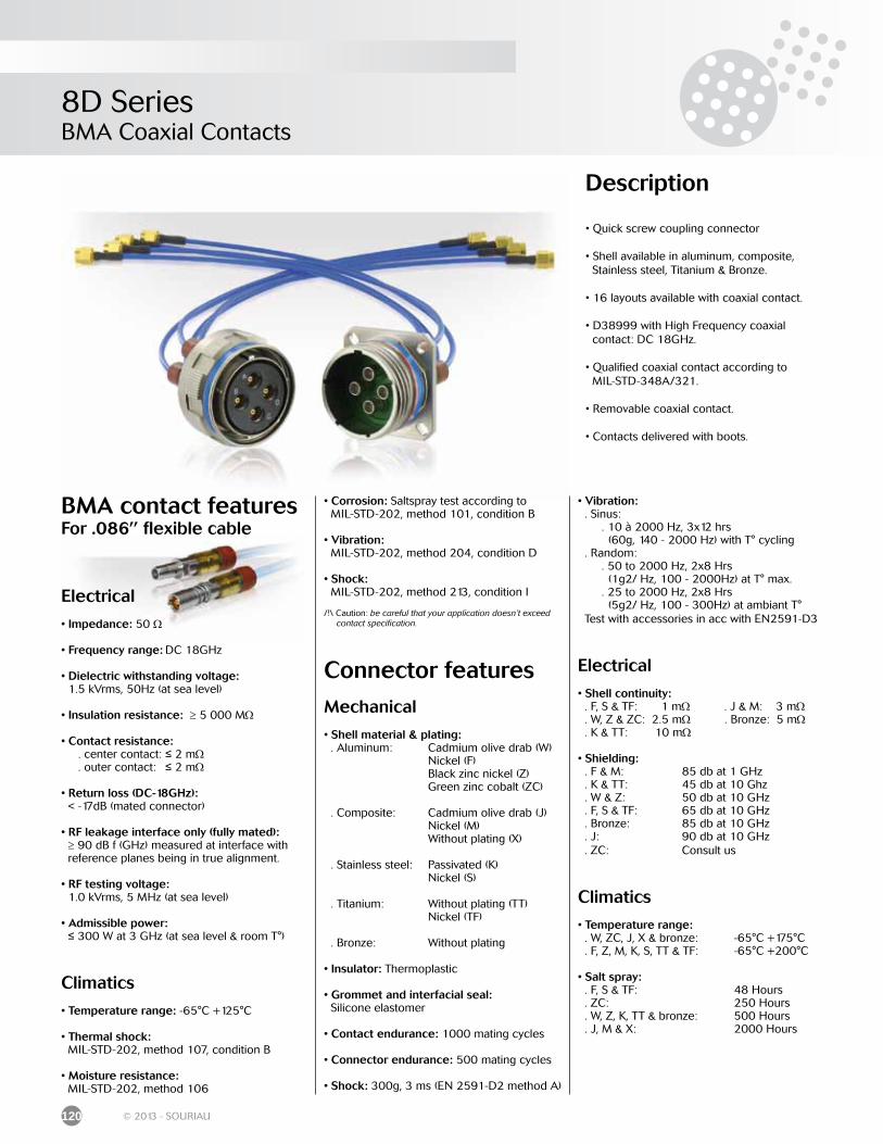
8D SeriesBMA Coaxial Contacts
120 © 2013 - SOURIAU
Description
• Quick screw coupling connector
• Shell available in aluminum, composite, Stainless steel, Titanium & Bronze.
• 16 layouts available with coaxial contact.
• D38999 with High Frequency coaxial contact: DC 18GHz.
• Qualified coaxial contact according to MIL-STD-348A/321.
• Removable coaxial contact.
• Contacts delivered with boots.
• Corrosion: Saltspray test according to MIL-STD-202, method 101, condition B
• Vibration: MIL-STD-202, method 204, condition D
• Shock: MIL-STD-202, method 213, condition I
/!\ Caution: be careful that your application doesn’t exceed contact specification.
Connector features
Mechanical
• Shell material & plating: . Aluminum: Cadmium olive drab (W) Nickel (F) Black zinc nickel (Z) Green zinc cobalt (ZC)
. Composite: Cadmium olive drab (J) Nickel (M) Without plating (X)
. Stainless steel: Passivated (K) Nickel (S)
. Titanium: Without plating (TT) Nickel (TF)
. Bronze: Without plating
• Insulator: Thermoplastic
• Grommet and interfacial seal: Silicone elastomer
• Contact endurance: 1000 mating cycles
• Connector endurance: 500 mating cycles
• Shock: 300g, 3 ms (EN 2591-D2 method A)
• Vibration: . Sinus: . 10 à 2000 Hz, 3x12 hrs (60g, 140 - 2000 Hz) with T° cycling . Random: . 50 to 2000 Hz, 2x8 Hrs (1g2/ Hz, 100 - 2000Hz) at T° max. . 25 to 2000 Hz, 2x8 Hrs (5g2/ Hz, 100 - 300Hz) at ambiant T° Test with accessories in acc with EN2591-D3
Electrical
• Shell continuity: . F, S & TF: 1 mΩ . J & M: 3 mΩ . W, Z & ZC: 2.5 mΩ . Bronze: 5 mΩ . K & TT: 10 mΩ
• Shielding: . F & M: 85 db at 1 GHz . K & TT: 45 db at 10 Ghz . W & Z: 50 db at 10 GHz . F, S & TF: 65 db at 10 GHz . Bronze: 85 db at 10 GHz . J: 90 db at 10 GHz . ZC: Consult us
Climatics
• Temperature range: . W, ZC, J, X & bronze: -65°C +175°C . F, Z, M, K, S, TT & TF: -65°C +200°C
• Salt spray: . F, S & TF: 48 Hours . ZC: 250 Hours . W, Z, K, TT & bronze: 500 Hours . J, M & X: 2000 Hours
BMA contact featuresFor .086’’ flexible cable
Electrical
• Impedance: 50 Ω
• Frequency range: DC 18GHz
• Dielectric withstanding voltage: 1.5 kVrms, 50Hz (at sea level)
• Insulation resistance: ≥ 5 000 MΩ
• Contact resistance: . center contact: ≤ 2 mΩ . outer contact: ≤ 2 mΩ
• Return loss (DC-18GHz): < -17dB (mated connector)
• RF leakage interface only (fully mated): ≥ 90 dB f (GHz) measured at interface with reference planes being in true alignment.
• RF testing voltage: 1.0 kVrms, 5 MHz (at sea level)
• Admissible power: ≤ 300 W at 3 GHz (at sea level & room T°)
Climatics
• Temperature range: -65°C +125°C
• Thermal shock: MIL-STD-202, method 107, condition B
• Moisture resistance: MIL-STD-202, method 106
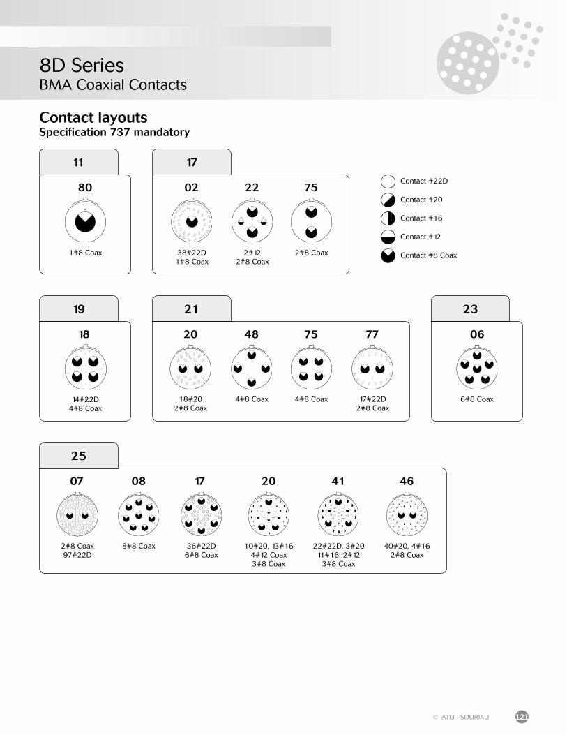
8D SeriesBMA Coaxial Contacts
121© 2013 - SOURIAU
Contact #22D
Contact #20
Contact #16
Contact #12
Contact #8 Coax
Contact layoutsSpecification 737 mandatory
80
1#8 Coax
11
02
38#22D1#8 Coax
22
2#122#8 Coax
75
2#8 Coax
17
18
14#22D4#8 Coax
19
20
18#202#8 Coax
48
4#8 Coax
75
4#8 Coax
77
17#22D2#8 Coax
21
6#8 Coax
06
23
2#8 Coax97#22D
07 08
8#8 Coax
17
36#22D6#8 Coax
20
10#20, 13#164#12 Coax3#8 Coax
41
22#22D, 3#2011#16, 2#12
3#8 Coax
46
40#20, 4#162#8 Coax
25
8D SeriesBMA Coaxial Contacts
122 © 2013 - SOURIAU
Ordering information
Basic Series 8D 0 25 W 46 P N 737
Shell style: 0: Square flange receptacle 1: In line receptacle 7: Jam nut receptacle 5: Plug with RFI shielding
Shell size: 11, 17, 19, 21, 23, 25Aluminum plating: W: Olive drab cadmium F: Nickel Z: Black zinc nickel
Contact layout: See previous page
Contact type: P: Pin S: Socket
Orientation: N, A, B, C, D, ESpecification (mandatory): 737: Coaxial contacts - for .086’’ flexible cable 747: Coaxial contacts - for .141’’ flexible cable
For other material and configuration (integrated clinch nuts, double flange, other cables, ...) please consult us.
Recommended cables
Designation Part number Description
.086’’ flexible cable Multiflex 86 Outer conductorcontact Soldered
.141’’ flexible cable Multiflex 141
For other cables please consult us.
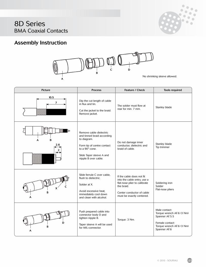
8D SeriesBMA Coaxial Contacts
123© 2013 - SOURIAU
Picture Process Feature / Check Tools required
Dip the cut length of cable in flux and tin.
Cut the jacket to the braid.Remove jacket.
The solder must flow atrear for min. 7 mm.
Stanley blade
Remove cable dielectricand tinned braid accordingto diagram.
Form tip of centre contactto a 90° cone.
Slide Taper sleeve A and nipple B over cable.
Do not damage innerconductor, dielectric and braid of cable.
Stanley bladeTip trimmer
Slide ferrule C over cable, flush to dielectric.
Solder at X.
Avoid excessive heat,immediately cool downand clean with alcohol.
If the cable does not fitinto the cable entry, use aflat-nose plier to calibratethe braid.
Center conductor of cable must be exactly centered.
Soldering ironSolderFlat-nose pliers
Push prepared cable into connector body D andtighten nipple B.
Taper sleeve A will be used for MIL-connector.
Torque: 3 Nm.
Male contact:Torque wrench AF.6 (3 Nm)Spanner AF.5.5
Female contact:Torque wrench AF.6 (3 Nm)Spanner AF.6
Assembly Instruction
10.5
7
2.6
2
A B
A
B
CX
AB
D
No shrinking sleeve allowed.A
BC D
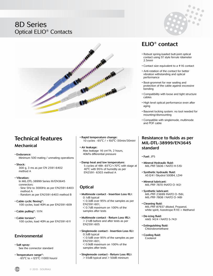
8D SeriesOptical ELIO® Contacts
124 © 2013 - SOURIAU
ELIO® contact
• Robust spring-loaded butt-joint optical contact using ST style ferrule (diameter 2.5mm)
• Contact size equivalent to a #16 contact
• Anti-rotation of the contact for better vibration withstanding and optical performance
• Boot-grommet for rear sealing and protection of the cable against excessive bending
• Compatibility with loose and tight structure cables
• High level optical performance even after aging
• Bayonet locking system: no tool needed for mounting/dismounting
• Compatible with singlemode, multimode and POF cable
Technical featuresMechanical
• Endurance: Minimum 500 mating / unmating operations
• Shock: 300 g, 3 ms as per EN 2591-6402 method A
• Vibration: In MIL-DTL-38999 Series III/EN3645 connectors: - Sine 5Hz to 3000Hz as per EN2591-6403 method A - Random as per EN2591-6403 method B
• Cable cyclic flexing*: 100 cycles, load 40N as per EN2591-609
• Cable pulling*: 111N
• Cable torsion*: 100 cycles, load 40N as per EN2591-611
Environmental
• Salt spray: See the connector standard
• Temperature range*: - 65°C to +125°C (1000 hours)
• Rapid temperature change: 10 cycles - 65°C / +150°C (30min/30min)
• Air leakage: Max leakage 16 cm3/h, 2 hours, 40kPa differential pressure
• Damp heat and low temperature: 5 cycles of 48h -65°C/+70°C with stage at 40°C with 95% of humidity as per EN2591- 6303 method A
Optical
• Multimode contact - Insertion Loss (IL): 0.1dB typical < 0.3dB over 95% of the samples as per EN2591-601, < 0.7dB maximum on 100% of the samples after tests
• Multimode contact - Return Loss (RL): > 21dB before and after tests as per EN2591-605
• Singlemode contact - Insertion Loss (IL): 0.3dB typical < 0.5dB over 95% of the samples as per EN2591-601, < 0.9dB maximum on 100% of the samples after tests
• Singlemode contact - Return Loss (RL): > 55dB typical and > 50dB mininum
Resistance to fluids as perMIL-DTL-38999/EN3645 standard
• Fuel: JP5
• Mineral Hydraulic fluid: MIL-PRF-5606 ( NATO H-515)
• Synthetic hydraulic fluid: AS1241 (Skydrol 500B4, LD4)
• Mineral lubricant: MIL-PRF-7870 (NATO O-142)
• Synthetic lubricant: MIL-PRF-23699 (NATO O-156), MIL-PRF-7808 ( NATO O-148)
• Cleaning fluid: MIL-PRF-87937 diluted, Propanol, white spirit, Azeotrope R113 + Methanol
• De-icing fluid: AMS 1424 ( NATO S-742)
• Extinguishing fluid: Chlorobromethane
• Cooling fluid: Coolanol
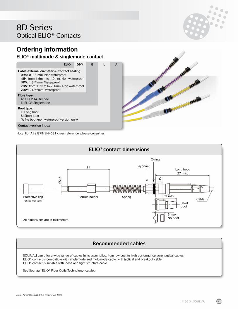
8D SeriesOptical ELIO® Contacts
125© 2013 - SOURIAU
Note: All dimensions are in millimeters (mm)
Ordering information
ELIO® contact dimensions
Ø2
.5
21
Ø5
27 max
12 max
6 max
CableProtective cap(shape may vary)
Ferrule holder
Bayonnet
Spring
O-ring
Long boot
Short boot
No bootAll dimensions are in millimeters.
Recommended cables
SOURIAU can offer a wide range of cables in its assemblies, from low cost to high performance aeronautical cables.ELIO® contact is compatible with singlemode and multimode cable, with tactical and breakout cable.ELIO® contact is suitable with loose and tight structure cable.
See Souriau ‘‘ELIO® Fiber Optic Technology» catalog.
Note: For ABS1379/EN4531 cross reference, please consult us.
ELIO 09N G L A
Cable external diameter & Contact sealing: 09N: 0.9±0.1mm. Non waterproof 18N: from 1.5mm to 1.9mm. Non waterproof 18W: 1.8±0.1mm. Waterproof 20N: from 1.7mm to 2.1mm. Non waterproof 20W: 2.0±0.1mm. Waterproof
Fibre type: G: ELIO® Multimode E: ELIO® Singlemode
Boot type: L: Long boot S: Short boot N: No boot (non waterproof version only)
Contact version index
ELIO® multimode & singlemode contact
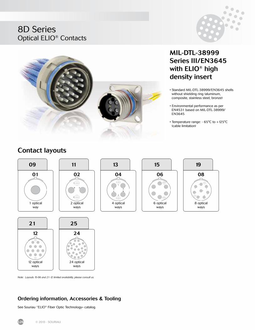
8D SeriesOptical ELIO® Contacts
126 © 2013 - SOURIAU
MIL-DTL-38999Series III/EN3645 with ELIO® highdensity insert
• Standard MIL-DTL-38999/EN3645 shells without shielding ring (aluminum, composite, stainless steel, bronze)
• Environmental performance as per EN4531 based on MIL-DTL-38999/ EN3645
• Temperature range: - 65°C to +125°C (cable limitation)
Ordering information, Accessories & Tooling
See Souriau ‘‘ELIO® Fiber Optic Technology» catalog.
Contact layouts
11
2 optical ways
02
13
4 optical ways
04
19
8 optical ways
08
09
1 optical way
01
15
6 optical ways
06
24 optical ways
24
2521
12 optical ways
12
Note: Layouts 15-06 and 21-12 limited availability, please consult us.
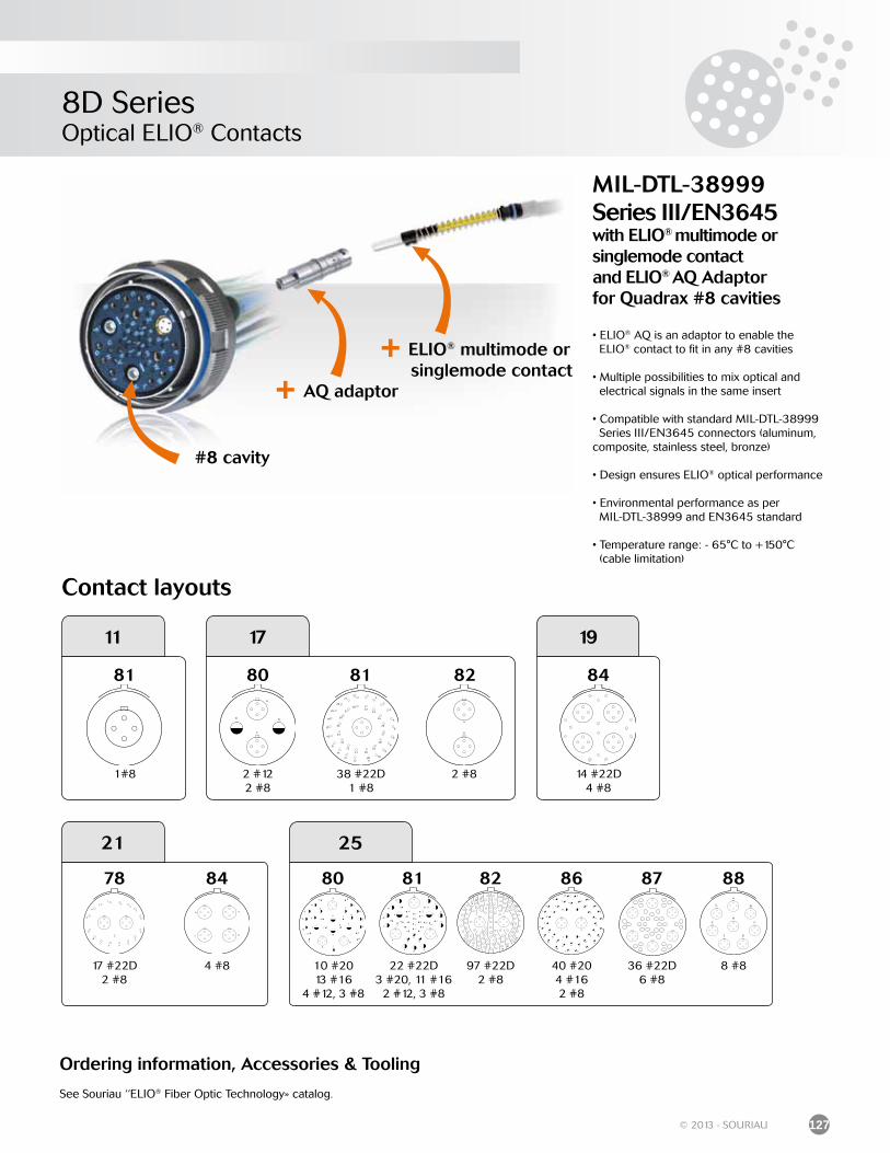
8D SeriesOptical ELIO® Contacts
127© 2013 - SOURIAU
MIL-DTL-38999Series III/EN3645with ELIO® multimode orsinglemode contactand ELIO® AQ Adaptorfor Quadrax #8 cavities
• ELIO® AQ is an adaptor to enable the ELIO® contact to fit in any #8 cavities
• Multiple possibilities to mix optical and electrical signals in the same insert
• Compatible with standard MIL-DTL-38999 Series III/EN3645 connectors (aluminum, composite, stainless steel, bronze)
• Design ensures ELIO® optical performance
• Environmental performance as per MIL-DTL-38999 and EN3645 standard
• Temperature range: - 65°C to +150°C (cable limitation)
#8 cavity
+ AQ adaptor
+ ELIO® multimode or singlemode contact
11
81
1#8
17
80 81 82
2 #838 #22D 1 #8
2 #122 #8
19
14 #22D 4 #8
84
21
4 #817 #22D 2 #8
8478
8 #897 #22D 2 #8
40 #204 #162 #8
22 #22D3 #20, 11 #16
2 #12, 3 #8
81 8882 86
25
80 87
10 #2013 #16
4 #12, 3 #8
36 #22D6 #8
Contact layouts
Ordering information, Accessories & Tooling
See Souriau ‘‘ELIO® Fiber Optic Technology» catalog.
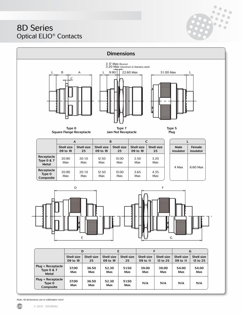
8D SeriesOptical ELIO® Contacts
128 © 2013 - SOURIAU
Dimensions
D
E
F
G
A B C
Shell size 09 to 19
Shell size 25
Shell size 09 to 19
Shell size 25
Shell size 09 to 19
Shell size 25
Receptacle Type 0 & 7
Metal
20.90 Max
20.10 Max
12.50 Max
13.00Max
2.50Max
3.20Max
Receptacle Type 0
Composite
20.90 Max
20.10 Max
12.50 Max
13.00 Max
3.65Max
4.35Max
L
Male insulator
Female insulator
4 Max 6.60 Max
D E F G
Shell size 09 to 19
Shell size 25
Shell size 09 to 19
Shell size 25
Shell size 09 to 11
Shell size 13 to 25
Shell size 09 to 11
Shell size 13 to 25
Plug + Receptacle Type 0 & 7
Metal
37.00 Max
36.50Max
52.30Max
51.50Max
39.00Max
39.00Max
54.00Max
54.00Max
Plug + Receptacle Type 0
Composite
37.00 Max
36.50 Max
52.30Max
51.50Max
N/A N/A N/A N/A
Note: All dimensions are in millimeters (mm)
L B
C
A L 9.90 22.60 Max L31.00 Max
Type 0Square Flange Receptacle
Type 7Jam Nut Receptacle
Type 5Plug
3.17 Max (Bronze)3.20 Max (Aluminum & Stainless steel)
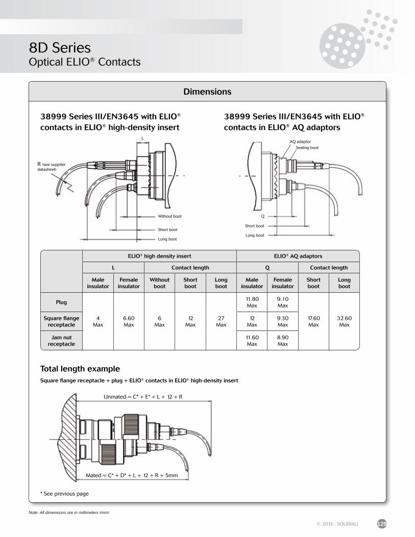
8D SeriesOptical ELIO® Contacts
129© 2013 - SOURIAU
Dimensions
ELIO® high density insert ELIO® AQ adaptors
L Contact length Q Contact length
Male insulator
Female insulator
Without boot
Short boot
Long boot
Male insulator
Female insulator
Short boot
Long boot
Plug
4Max
6.60Max
6Max
12Max
27Max
11.80Max
9.10Max
17.60Max
32.60Max
Square flange receptacle
12Max
9.30Max
Jam nutreceptacle
11.60Max
8.90Max
38999 Series III/EN3645 with ELIO® contacts in ELIO® high-density insert
38999 Series III/EN3645 with ELIO® contacts in ELIO® AQ adaptors
Long boot
Short boot
Without boot
L
Total length exampleSquare flange receptacle + plug + ELIO® contacts in ELIO® high-density insert
R (see supplier datasheet)
Unmated = C* + E* + L + 12 + R
Mated = C* + D* + L + 12 + R + 5mm
* See previous page
Note: All dimensions are in millimeters (mm)
Long boot
Short boot
Q
AQ adaptor
Sealing boot
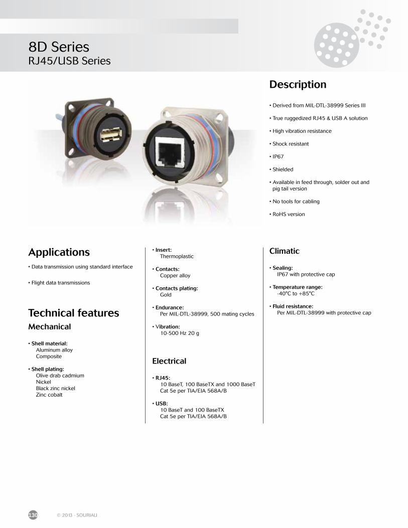
8D SeriesRJ45/USB Series
130 © 2013 - SOURIAU
Description
• Derived from MIL-DTL-38999 Series III
• True ruggedized RJ45 & USB A solution
• High vibration resistance
• Shock resistant
• IP67
• Shielded
• Available in feed through, solder out and pig tail version
• No tools for cabling
• RoHS version
Applications• Data transmission using standard interface
• Flight data transmissions
Technical featuresMechanical
• Shell material: Aluminum alloy Composite • Shell plating: Olive drab cadmium Nickel Black zinc nickel Zinc cobalt
• Insert: Thermoplastic
• Contacts: Copper alloy
• Contacts plating: Gold
• Endurance: Per MIL-DTL-38999, 500 mating cycles
• Vibration: 10-500 Hz 20 g
Electrical
• RJ45: 10 BaseT, 100 BaseTX and 1000 BaseT Cat 5e per TIA/EIA 568A/B
• USB: 10 BaseT and 100 BaseTX Cat 5e per TIA/EIA 568A/B
Climatic
• Sealing: IP67 with protective cap
• Temperature range: -40°C to +85°C
• Fluid resistance: Per MIL-DTL-38999 with protective cap
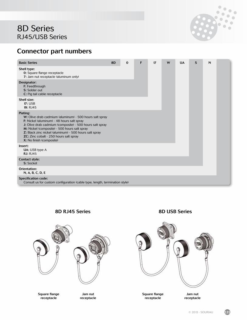
8D SeriesRJ45/USB Series
131© 2013 - SOURIAU
8D RJ45 Series 8D USB Series
Square flange receptacle
Square flange receptacle
Jam nut receptacle
Jam nut receptacle
Basic Series 8D 0 F 17 W UA S N
Shell type: 0: Square flange receptacle 7: Jam nut receptacle (aluminum only)
Designator: F: Feedthrough S: Solder out C: Pig tail cable receptacle
Shell size: 17: USB 19: RJ45
Plating: W: Olive drab cadmium (aluminum) - 500 hours salt spray F: Nickel (aluminum) - 48 hours salt spray J: Olive drab cadmium (composite) - 500 hours salt spray M: Nickel (composite) - 500 hours salt spray Z: Black zinc nickel (aluminum) - 500 hours salt spray ZC: Zinc cobalt - 250 hours salt spray X: No finish (composite)
Insert: UA: USB type A RJ: RJ45
Contact style: S: Socket
Orientation: N, A, B, C, D, E
Specification code: Consult us for custom configuration (cable type, length, termination style)
Connector part numbers
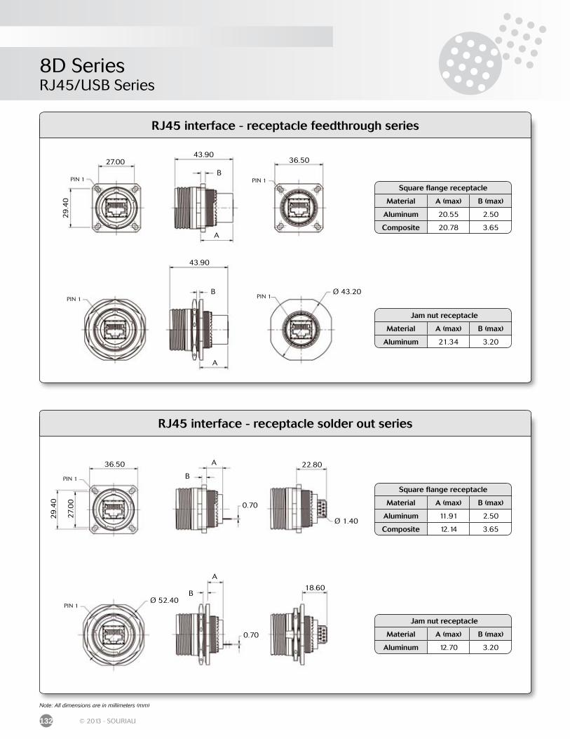
8D SeriesRJ45/USB Series
132 © 2013 - SOURIAU
RJ45 interface - receptacle feedthrough series
RJ45 interface - receptacle solder out series
Jam nut receptacle
Material A (max) B (max)
Aluminum 21.34 3.20
Square flange receptacle
Material A (max) B (max)
Aluminum 20.55 2.50
Composite 20.78 3.65
PIN 1
27.00
29
.40
B
A
43.9036.50
PIN 1
B
A
43.90
PIN 1 PIN 1Ø 43.20
Note: All dimensions are in millimeters (mm)
Jam nut receptacle
Material A (max) B (max)
Aluminum 12.70 3.20
Square flange receptacle
Material A (max) B (max)
Aluminum 11.91 2.50
Composite 12.14 3.65
PIN 1
36.50
29
.40
B
A
0.70
22.80
B
A
0.70
PIN 1Ø 52.40
27.
00
Ø 1.40
18.60
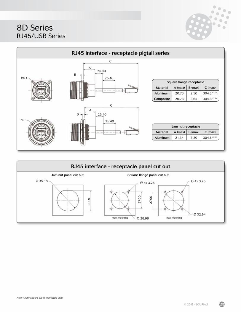
8D SeriesRJ45/USB Series
133© 2013 - SOURIAU
RJ45 interface - receptacle pigtail series
Jam nut receptacle
Material A (max) B (max) C (max)
Aluminum 21.34 3.20 304.8 ±25.4
Square flange receptacle
Material A (max) B (max) C (max)
Aluminum 20.78 2.50 304.8 ±25.4
Composite 20.78 3.65 304.8 ±25.4
Note: All dimensions are in millimeters (mm)
PIN 1B
C
25.40A
25.40
B
PIN 1
C
A25.40
25.40
RJ45 interface - receptacle panel cut out
Front mounting Rear mounting
Ø 35.18
33
.91
27.
00
27.
00
Ø 28.98
Ø 4x 3.25 Ø 4x 3.25
Ø 32.94
Jam nut panel cut out Square flange panel cut out
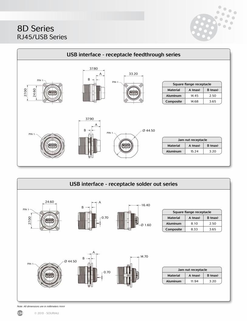
8D SeriesRJ45/USB Series
134 © 2013 - SOURIAU
USB interface - receptacle feedthrough series
USB interface - receptacle solder out series
Note: All dimensions are in millimeters (mm)
Jam nut receptacle
Material A (max) B (max)
Aluminum 15.24 3.20
Square flange receptacle
Material A (max) B (max)
Aluminum 14.45 2.50
Composite 14.68 3.65
Jam nut receptacle
Material A (max) B (max)
Aluminum 11.94 3.20
Square flange receptacle
Material A (max) B (max)
Aluminum 8.10 2.50
Composite 8.33 3.65
PIN 1
33.20
PIN 1
PIN 1
PIN 1
37.80
27.
00
24
.60
A
B
37.90
A
B Ø 44.50
PIN 1
PIN 1
A
B
A
B
27.
00
24.60
0.70
16.40
Ø 1.60
Ø 44.50
0.70
14.70
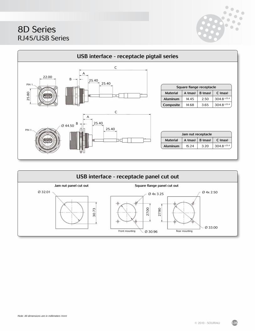
8D SeriesRJ45/USB Series
135© 2013 - SOURIAU
Note: All dimensions are in millimeters (mm)
Jam nut receptacle
Material A (max) B (max) C (max)
Aluminum 15.24 3.20 304.8 ±25.4
Square flange receptacle
Material A (max) B (max) C (max)
Aluminum 14.45 2.50 304.8 ±25.4
Composite 14.68 3.65 304.8 ±25.4
Front mounting Rear mounting
Ø 32.01
30
.73
27.
00
27.
90
Ø 30.96
Ø 4x 3.25 Ø 4x 2.50
Ø 33.00
Jam nut panel cut out Square flange panel cut out
USB interface - receptacle panel cut out
USB interface - receptacle pigtail series
B
PIN 1
CA
25.40
25.40Ø 44.50
PIN 1
B
C
25.40
A
25.40
22.00
25
.80

8D Series
Range Extension8D Series
micro38999 ......................................................................................................................................
8D hermetic ELIO® feedthrough ................................................................................................
Rack & panel .....................................................................................................................................
230V connector ..............................................................................................................................
8D8 / 8D9 Series ............................................................................................................................
8DB bulkhead feedthrough .........................................................................................................
8PS Series ..........................................................................................................................................
8D hermetic aluminum 38999 power & signal connector ...............................................
8D36 lanyard release ....................................................................................................................
8TFD filter connector .....................................................................................................................
138
138
139
139
140
140
141
141
142
142
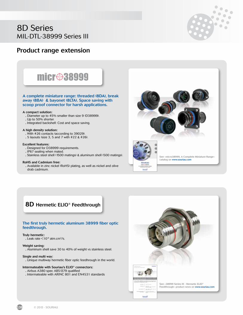
8D SeriesMIL-DTL-38999 Series III
138 © 2013 - SOURIAU
Product range extension
See «micro38999, A Complete Miniature Range» catalog on www.souriau.com
A complete miniature range: threaded (8DA), break away (8BA) & bayonet (8LTA). Space saving with scoop proof connector for harsh applications.
A compact solution: . Diameter up to 45% smaller than size 9 (D38999). . Up to 50% shorter. . Integrated backshell: Cost and space saving.
A high density solution: . With #26 contacts (according to 39029). . 5 layouts (size 3, 5 and 7 with #22 & #26).
Excellent features: . Designed for D38999 requirements. . IP67 sealing when mated. . Stainless steel shell (1500 matings) & aluminum shell (500 matings).
RoHS and Cadmium free: . Available in zinc nickel (RoHS) plating, as well as nickel and olive drab cadmium.
8D Hermetic ELIO® Feedthrough
See «38999 Series III - Hermetic ELIO® Feedthrough» product news on www.souriau.com
The first truly hermetic aluminum 38999 fiber optic feedthrough.
Truly hermetic: . Leak rate <10-9 atm.cm3/s.
Weight saving: . Aluminum shell save 30 to 40% of weight vs stainless steel.
Single and multi way: . Unique multiway hermetic fiber optic feedhrough in the world.
Intermateable with Souriau’s ELIO® connectors: . Airbus A380 spec ABS1379 qualified . Intermateable with ARINC 801 and EN4531 standards
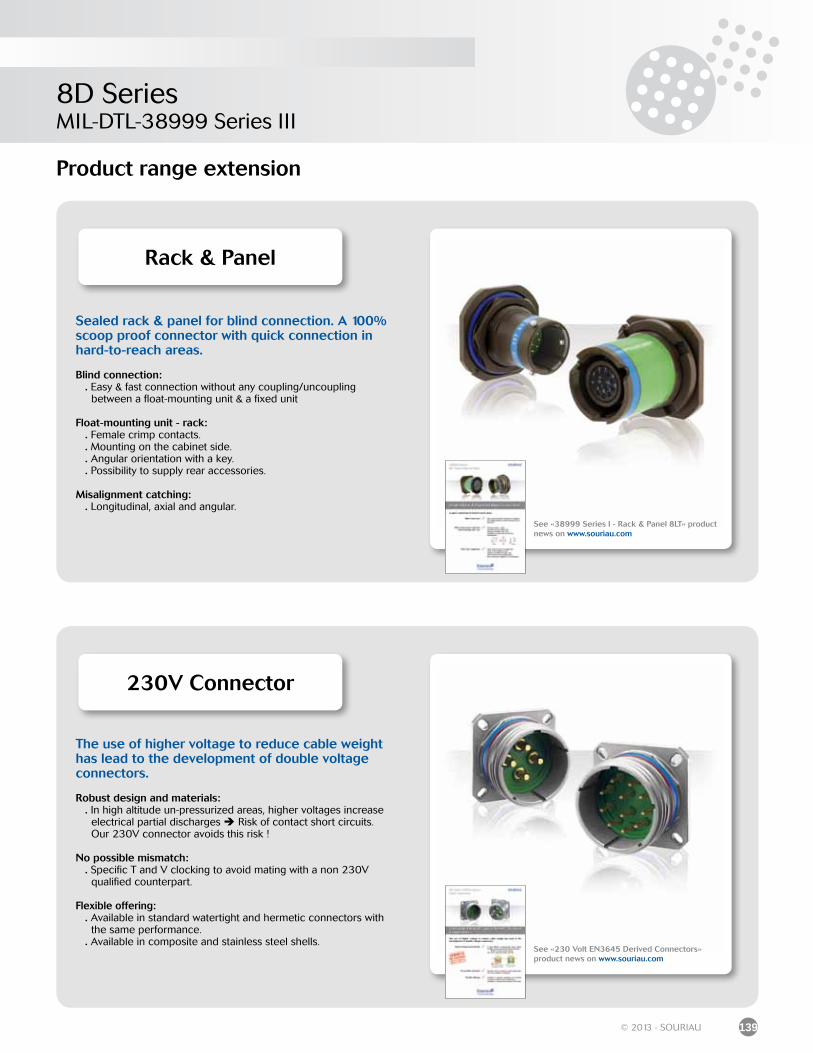
8D SeriesMIL-DTL-38999 Series III
139© 2013 - SOURIAU
Product range extension
Rack & Panel
See «38999 Series I - Rack & Panel 8LT» product news on www.souriau.com
230V Connector
The use of higher voltage to reduce cable weight has lead to the development of double voltage connectors.
Robust design and materials: . In high altitude un-pressurized areas, higher voltages increase electrical partial discharges Risk of contact short circuits. Our 230V connector avoids this risk !
No possible mismatch: . Specific T and V clocking to avoid mating with a non 230V qualified counterpart.
Flexible offering: . Available in standard watertight and hermetic connectors with the same performance. . Available in composite and stainless steel shells.
Sealed rack & panel for blind connection. A 100% scoop proof connector with quick connection in hard-to-reach areas.
Blind connection: . Easy & fast connection without any coupling/uncoupling between a float-mounting unit & a fixed unit
Float-mounting unit - rack: . Female crimp contacts. . Mounting on the cabinet side. . Angular orientation with a key. . Possibility to supply rear accessories.
Misalignment catching: . Longitudinal, axial and angular.
See «230 Volt EN3645 Derived Connectors» product news on www.souriau.com
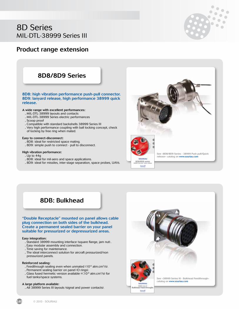
8D SeriesMIL-DTL-38999 Series III
140 © 2013 - SOURIAU
Product range extension
8D8/8D9 Series
See «8D8/8D9 Series - 38999 Push pull/Quick release» catalog on www.souriau.com
8D8: high vibration performance push-pull connector. 8D9: lanyard release, high performance 38999 quick release.
A wide range with excellent performances: . MIL-DTL-38999 layouts and contacts . MIL-DTL-38999 Series electric performances . Scoop proof . Compatible with standard backshells 38999 Series III . Very high performance coupling with ball locking concept, check of locking by free ring when mated.
Easy to connect-disconnect: . 8D8: ideal for restricted space mating. . 8D9: simple push to connect - pull to disconnect.
High vibration performance: . Up to 44g . 8D8: ideal for mil-aero and space applications. . 8D9: ideal for missiles, inter-stage separation, space probes, UAVs.
8DB: Bulkhead
See «38999 Series III - Bulkhead Feedthrough» catalog on www.souriau.com
“Double Receptacle” mounted on panel allows cable plug connection on both sides of the bulkhead. Create a permanent sealed barrier on your panel suitable for pressurized or depressurized areas.
Easy integration: . Standard 38999 mounting interface (square flange, jam nut).. . Easy modular assembly and connection. . Time saving for maintenance. . The ideal interconnect solution for aircraft pressurized/non pressurized panels.
Reinforced sealing: . Feedthrough sealing even when unmated (10-6 atm.cm3/s). . Permanent sealing barrier on panel (O rings). . Glass fused hermetic version available (<10-8 atm.cm3/s) for fuel tanks/space systems.
A large platform available: . All 38999 Series III layouts (signal and power contacts).
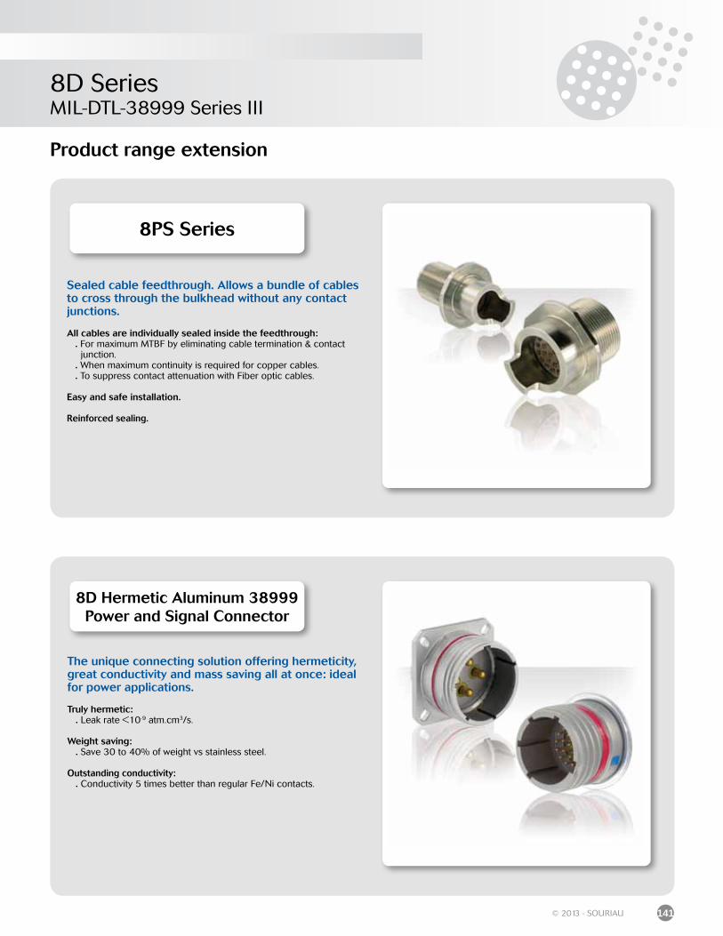
8D SeriesMIL-DTL-38999 Series III
141© 2013 - SOURIAU
Product range extension
8D Hermetic Aluminum 38999 Power and Signal Connector
The unique connecting solution offering hermeticity, great conductivity and mass saving all at once: ideal for power applications.
Truly hermetic: . Leak rate <10-9 atm.cm3/s.
Weight saving: . Save 30 to 40% of weight vs stainless steel.
Outstanding conductivity: . Conductivity 5 times better than regular Fe/Ni contacts.
8PS Series
Sealed cable feedthrough. Allows a bundle of cables to cross through the bulkhead without any contact junctions.
All cables are individually sealed inside the feedthrough: . For maximum MTBF by eliminating cable termination & contact junction. . When maximum continuity is required for copper cables. . To suppress contact attenuation with Fiber optic cables.
Easy and safe installation.
Reinforced sealing.
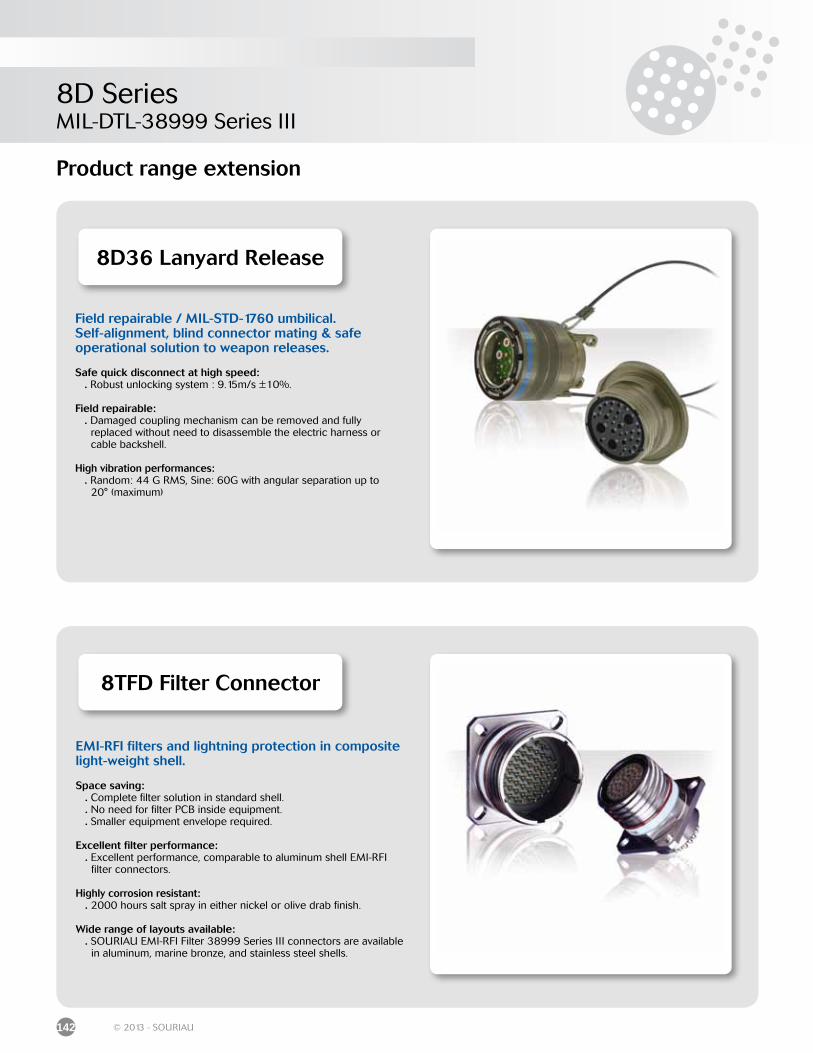
8D SeriesMIL-DTL-38999 Series III
142 © 2013 - SOURIAU
Product range extension
8D36 Lanyard Release
Field repairable / MIL-STD-1760 umbilical.Self-alignment, blind connector mating & safeoperational solution to weapon releases.
Safe quick disconnect at high speed: . Robust unlocking system : 9.15m/s ±10%.
Field repairable: . Damaged coupling mechanism can be removed and fully replaced without need to disassemble the electric harness or cable backshell.
High vibration performances: . Random: 44 G RMS, Sine: 60G with angular separation up to 20° (maximum)
8TFD Filter Connector
EMI-RFI filters and lightning protection in composite light-weight shell.
Space saving: . Complete filter solution in standard shell. . No need for filter PCB inside equipment. . Smaller equipment envelope required.
Excellent filter performance: . Excellent performance, comparable to aluminum shell EMI-RFI filter connectors.
Highly corrosion resistant: . 2000 hours salt spray in either nickel or olive drab finish.
Wide range of layouts available: . SOURIAU EMI-RFI Filter 38999 Series III connectors are available in aluminum, marine bronze, and stainless steel shells.

© C
opyr
ight
SO
UR
IAU
Mar
ch 2
013
- A
ll in
form
atio
n in
thi
s do
cum
ent
pres
ents
onl
y ge
nera
l par
ticul
ars
and
shal
l not
form
par
t of
any
con
trac
t. A
ll rig
hts
rese
rved
to
SOU
RIA
U fo
r ch
ange
s w
ithou
t pr
ior
notifi
catio
n or
pub
lic a
nnou
ncem
ent.
Any
dup
licat
ion
is p
rohi
bite
d, u
nles
s ap
prov
ed in
writ
ing.