PRODUCT NAME Compact Air Gripper - :: SMC ::€¦ · PRODUCT NAME Compact Air Gripper MODEL/...
18
Doc. No. MH*-OMF0021-A PRODUCT NAME Compact Air Gripper MODEL/ Series/ Product Number MHF2-8D MHF2-12D MHF2-16D MHF2-20D
Transcript of PRODUCT NAME Compact Air Gripper - :: SMC ::€¦ · PRODUCT NAME Compact Air Gripper MODEL/...

Doc. No. MH*-OMF0021-A
PRODUCT NAME
Compact Air Gripper
MODEL/ Series/ Product Number
MHF2-8D
MHF2-12D
MHF2-16D
MHF2-20D

- 1 -
Contents
Safety Instructions
1. Product Specifications
1-1.Specifications
2. Operating Method / Operation
2-1. Precautions for Design
2-2. Selection
2-3. Installation
2-4. Air supply
2-5 Piping
2-6. Operating Environment
2-7. Lubrication
3. Maintenance.
3-1. Precautions
3-2 Disassembly Drawing 1
Disassembly Drawing 2
3-3. Seal Replacement Procedure 1
Seal Replacement Procedure 2
3-4 Construction/Parts list 1
Construction/Parts list 2
- 2 -
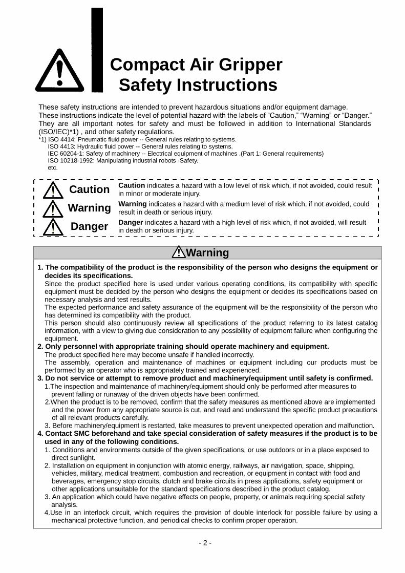
Compact Air Gripper Safety Instructions These safety instructions are intended to prevent hazardous situations and/or equipment damage. These instructions indicate the level of potential hazard with the labels of “Caution,” “Warning” or “Danger.” They are all important notes for safety and must be followed in addition to International Standards (ISO/IEC)*1) , and other safety regulations. *1) ISO 4414: Pneumatic fluid power -- General rules relating to systems. ISO 4413: Hydraulic fluid power -- General rules relating to systems. IEC 60204-1: Safety of machinery -- Electrical equipment of machines .(Part 1: General requirements) ISO 10218-1992: Manipulating industrial robots -Safety. etc.
Caution Caution indicates a hazard with a low level of risk which, if not avoided, could result in minor or moderate injury.
Warning Warning indicates a hazard with a medium level of risk which, if not avoided, could
result in death or serious injury.
Danger Danger indicates a hazard with a high level of risk which, if not avoided, will result in death or serious injury.
Warning 1. The compatibility of the product is the responsibility of the person who designs the equipment or
decides its specifications. Since the product specified here is used under various operating conditions, its compatibility with specific equipment must be decided by the person who designs the equipment or decides its specifications based on necessary analysis and test results. The expected performance and safety assurance of the equipment will be the responsibility of the person who has determined its compatibility with the product. This person should also continuously review all specifications of the product referring to its latest catalog information, with a view to giving due consideration to any possibility of equipment failure when configuring the equipment.
2. Only personnel with appropriate training should operate machinery and equipment. The product specified here may become unsafe if handled incorrectly. The assembly, operation and maintenance of machines or equipment including our products must be performed by an operator who is appropriately trained and experienced.
3. Do not service or attempt to remove product and machinery/equipment until safety is confirmed. 1.The inspection and maintenance of machinery/equipment should only be performed after measures to
prevent falling or runaway of the driven objects have been confirmed. 2.When the product is to be removed, confirm that the safety measures as mentioned above are implemented and the power from any appropriate source is cut, and read and understand the specific product precautions of all relevant products carefully. 3. Before machinery/equipment is restarted, take measures to prevent unexpected operation and malfunction.
4. Contact SMC beforehand and take special consideration of safety measures if the product is to be used in any of the following conditions. 1. Conditions and environments outside of the given specifications, or use outdoors or in a place exposed to direct sunlight. 2. Installation on equipment in conjunction with atomic energy, railways, air navigation, space, shipping,
vehicles, military, medical treatment, combustion and recreation, or equipment in contact with food and beverages, emergency stop circuits, clutch and brake circuits in press applications, safety equipment or other applications unsuitable for the standard specifications described in the product catalog.
3. An application which could have negative effects on people, property, or animals requiring special safety analysis.
4.Use in an interlock circuit, which requires the provision of double interlock for possible failure by using a mechanical protective function, and periodical checks to confirm proper operation.

- 3 -
Compact Air Gripper Safety Instructions
Caution 1.The product is provided for use in manufacturing industries.
The product herein described is basically provided for peaceful use in manufacturing industries. If considering using the product in other industries, consult SMC beforehand and exchange specifications or a contract if necessary. If anything is unclear, contact your nearest sales branch.
Limited warranty and Disclaimer/Compliance Requirements The product used is subject to the following “Limited warranty and Disclaimer” and “Compliance Requirements”. Read and accept them before using the product.
Limited warranty and Disclaimer
1.The warranty period of the product is 1 year in service or 1.5 years after the product is
delivered,whichever is first.2) Also, the product may have specified durability, running distance or replacement parts. Please consult your nearest sales branch.
2. For any failure or damage reported within the warranty period which is clearly our responsibility, a replacement product or necessary parts will be provided. This limited warranty applies only to our product independently, and not to any other damage
incurred due to the failure of the product.
3. Prior to using SMC products, please read and understand the warranty terms and disclaimers
noted in the specified catalog for the particular products.
2) Vacuum pads are excluded from this 1 year warranty. A vacuum pad is a consumable part, so it is warranted for a year after it is delivered.
Also, even within the warranty period, the wear of a product due to the use of the vacuum pad or failure due to the deterioration of rubber material are not covered by the limited
warranty.
Compliance Requirements
1. The use of SMC products with production equipment for the manufacture of weapons of mass destruction(WMD) or any other weapon is strictly prohibited.
2. The exports of SMC products or technology from one country to another are govemed by the relevant security laws and regulation of the countries involved in the transaction. Prior to the shipment of a SMC product to another country, assure that all local rules goveming that export
are known and followed.
The product is provided for use in manufacturing industries. The product herein described is basically provided for peaceful use in manufacturing industries. If considering using the product in other industries, consult SMC beforehand and provide specifications or a contract, if necessary.
契約などを行ってください。 The product is provided for use in manufacturing industries. The product herein described is basically provided for peaceful use in manufacturing industries. If considering using the product in other industries, consult SMC beforehand and provide specifications or a contract, if necessary.
契約などを行ってください。
- 4 -
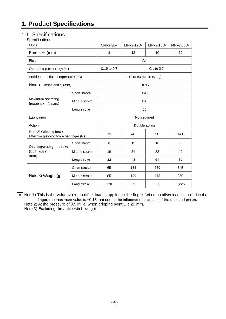
1. Product Specifications
1-1. Specifications Specifications
Model MHF2-8D MHF2-12D MHF2-16D MHF2-20D
Bore size (mm) 8 12 16 20
Fluid Air
Operating pressure (MPa) 0.15 to 0.7 0.1 to 0.7
Ambient and fluid temperature (oC) -10 to 60 (No freezing)
Note 1) Repeatability (mm) 0.05
Maximum operating
frequency (c.p.m.)
Short stroke 120
Middle stroke 120
Long stroke 60
Lubrication Not required
Action Double acting
Note 2) Gripping force
Effective gripping force per finger (N) 19 48 90 141
Opening/closing stroke
(Both sides)
(mm)
Short stroke 8 12 16 20
Middle stroke 16 24 32 40
Long stroke 32 48 64 80
Note 3) Weight (g)
Short stroke 65 155 350 645
Middle stroke 85 190 445 850
Long stroke 120 275 650 1,225
Note1) This is the value when no offset load is applied to the finger. When an offset load is applied to the
finger, the maximum value is 0.15 mm due to the influence of backlash of the rack and pinion. Note 2) At the pressure of 0.5 MPa, when gripping point L is 20 mm. Note 3) Excluding the auto switch weight.
A
- 5 -
2. Operating Method / Operation
2-1. Precautions for Design
! Warning 1. The product is designed for use only in compressed air systems.Do not operate at pressures or
temperatures, etc., beyond the range of the specifications, as this can cause damage or malfunction of the cylinder and other equipment. (Refer to the specifications.) Please contact SMC if using fluids other than compressed air. SMC does not guarantee against any damage if the product is used outside of the specification range.
2. Take safety measures (e.g. mounting protective covers) when there is a danger of fingers being caught in a gripper or workpieces causing damage etc.
3. There is a danger of workpieces dropping if there is a decrease in gripping force due to a drop in circuit pressure caused by a power failure, etc.It is necessary to take measures such as drop prevention so that injury and damage to machinery or equipment can be prevented.
4. If the product is used for a purpose other than the transportation of a workpiece such as positioning or clamping, please consult SMC.
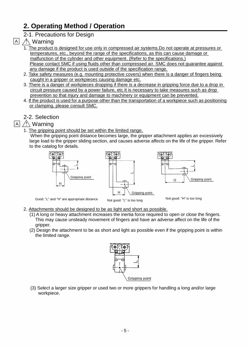
2-2. Selection
! Warning 1. The gripping point should be set within the limited range. When the gripping point distance becomes large, the gripper attachment applies an excessively
large load to the gripper sliding section, and causes adverse affects on the life of the gripper. Refer to the catalog for details.
2. Attachments should be designed to be as light and short as possible.
(1) A long or heavy attachment increases the inertia force required to open or close the fingers. This may cause unsteady movement of fingers and have an adverse affect on the life of the gripper.
(2) Design the attachment to be as short and light as possible even if the gripping point is within the limited range.
(3) Select a larger size gripper or used two or more grippers for handling a long and/or large
workpiece.
A
A
Gripping point
Gripping point Gripping point
Good: "L" and "H" are appropriate distance Not good: "L" is too long Not good: "H" is too long
Gripping point
- 6 -
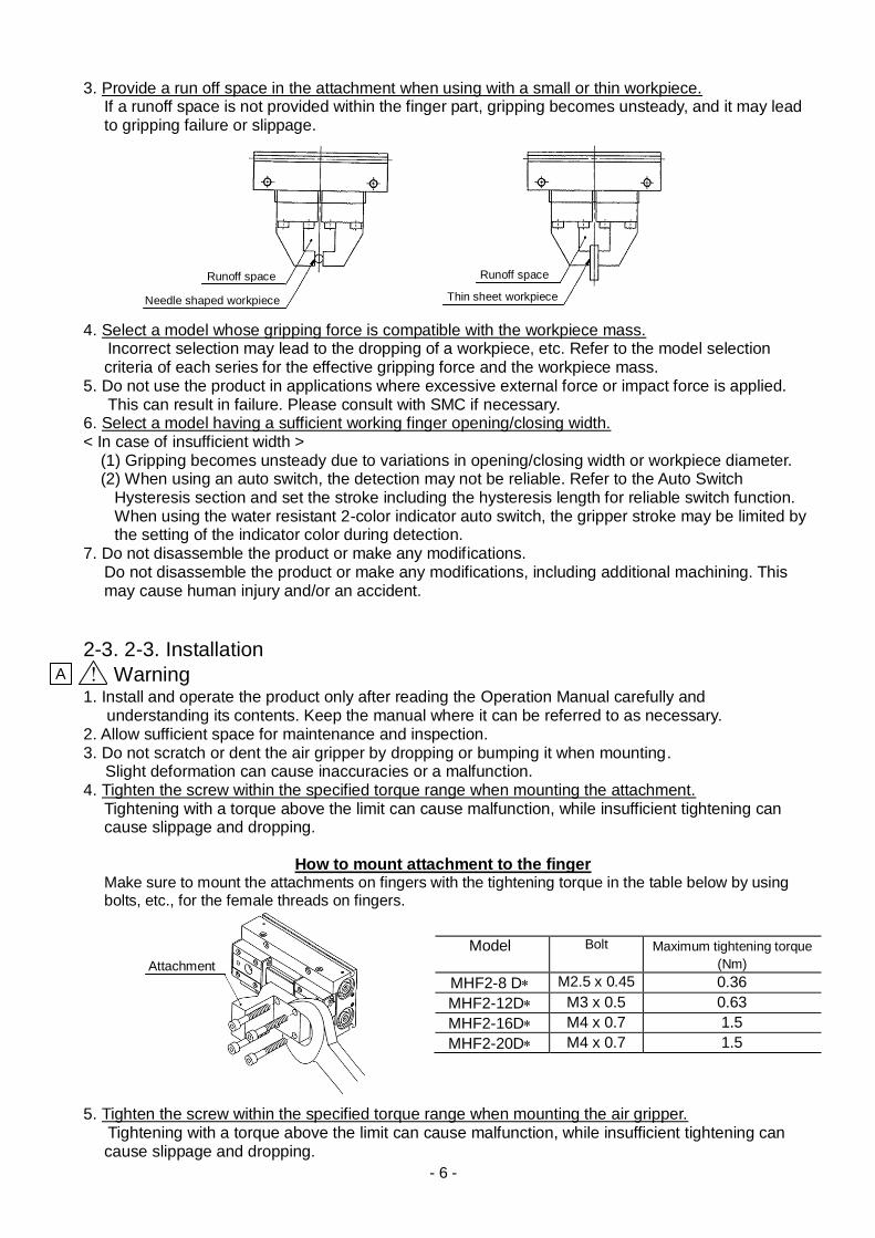
3. Provide a run off space in the attachment when using with a small or thin workpiece. If a runoff space is not provided within the finger part, gripping becomes unsteady, and it may lead to gripping failure or slippage.
4. Select a model whose gripping force is compatible with the workpiece mass. Incorrect selection may lead to the dropping of a workpiece, etc. Refer to the model selection
criteria of each series for the effective gripping force and the workpiece mass. 5. Do not use the product in applications where excessive external force or impact force is applied. This can result in failure. Please consult with SMC if necessary. 6. Select a model having a sufficient working finger opening/closing width. < In case of insufficient width >
(1) Gripping becomes unsteady due to variations in opening/closing width or workpiece diameter. (2) When using an auto switch, the detection may not be reliable. Refer to the Auto Switch
Hysteresis section and set the stroke including the hysteresis length for reliable switch function. When using the water resistant 2-color indicator auto switch, the gripper stroke may be limited by the setting of the indicator color during detection.
7. Do not disassemble the product or make any modifications. Do not disassemble the product or make any modifications, including additional machining. This may cause human injury and/or an accident.
2-3. 2-3. Installation
! Warning
1. Install and operate the product only after reading the Operation Manual carefully and understanding its contents. Keep the manual where it can be referred to as necessary.
2. Allow sufficient space for maintenance and inspection. 3. Do not scratch or dent the air gripper by dropping or bumping it when mounting.
Slight deformation can cause inaccuracies or a malfunction. 4. Tighten the screw within the specified torque range when mounting the attachment.
Tightening with a torque above the limit can cause malfunction, while insufficient tightening can cause slippage and dropping.
How to mount attachment to the finger
Make sure to mount the attachments on fingers with the tightening torque in the table below by using bolts, etc., for the female threads on fingers.
5. Tighten the screw within the specified torque range when mounting the air gripper. Tightening with a torque above the limit can cause malfunction, while insufficient tightening can
cause slippage and dropping.
Model Bolt Maximum tightening torque (Nm)
MHF2-8 D M2.5 x 0.45 0.36
MHF2-12D M3 x 0.5 0.63
MHF2-16D M4 x 0.7 1.5
MHF2-20D M4 x 0.7 1.5
A
Runoff space Runoff space
Needle shaped workpiece Thin sheet workpiece
Attachment
- 7 -
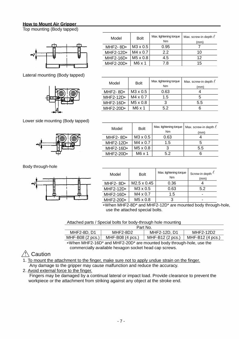
How to Mount Air Gripper Top mounting (Body tapped) Lateral mounting (Body tapped) Lower side mounting (Body tapped) Body through-hole
! Caution
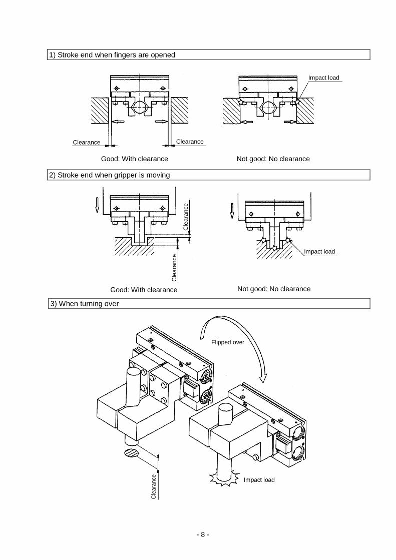
1. To mount the attachment to the finger, make sure not to apply undue strain on the finger. Any damage to the gripper may cause malfunction and reduce the accuracy. 2. Avoid external force to the finger. Fingers may be damaged by a continual lateral or impact load. Provide clearance to prevent the
workpiece or the attachment from striking against any object at the stroke end.
Model Bolt Max. tightening torque
Nm Max. screw-in depth
(mm)
MHF2- 8D M3 x 0.5 0.95 7
MHF2-12D M4 x 0.7 2.2 10
MHF2-16D M5 x 0.8 4.5 12
MHF2-20D M6 x 1 7.8 15
Model Bolt Max. tightening torque
Nm Max. screw-in depth
(mm)
MHF2- 8D M3 x 0.5 0.63 4
MHF2-12D M4 x 0.7 1.5 5
MHF2-16D M5 x 0.8 3 5.5
MHF2-20D M6 x 1 5.2 6
Model Bolt Max. tightening torque
Nm Max. screw-in depth
(mm)
MHF2- 8D M3 x 0.5 0.63 4
MHF2-12D M4 x 0.7 1.5 5
MHF2-16D M5 x 0.8 3 5.5
MHF2-20D M6 x 1 5.2 6
Model Bolt Max. tightening torque
Nm Screw-in depth
(mm)
MHF2- 8D M2.5 x 0.45 0.36 4
MHF2-12D M3 x 0.5 0.63 5.2
MHF2-16D M4 x 0.7 1.5 -
MHF2-20D M5 x 0.8 3 -
When MHF2-8D* and MHF2-12D* are mounted body through-hole, use the attached special bolts.
Attached parts / Special bolts for body-through hole mounting
Part No.
MHF2-8D, D1 MHF2-8D2 MHF2-12D, D1 MHF2-12D2
MHF-B08 (2 pcs.) MHF-B08 (4 pcs.) MHF-B12 (2 pcs.) MHF-B12 (4 pcs.)
When MHF2-16D* and MHF2-20D* are mounted body through-hole, use the commercially available hexagon socket head cap screws.
- 8 -
1) Stroke end when fingers are opened
2) Stroke end when gripper is moving
3) When turning over
Good: With clearance Not good: No clearance
Good: With clearance Not good: No clearance
Clearance Clearance
Impact load
Cle
ara
nce
Cle
ara
nce Impact load
Flipped over
Impact load
Cle
ara
nce

- 9 -
3. Adjust the gripping point so that an excessive force will not be applied to the fingers when inserting a workpiece. Confirm that the gripper can operate without receiving any shock by testing it in manual operation mode or by low speed operation.
4. Adjust the finger opening/closing speed with speed controllers so that the speed is not too fast.
If the finger opening/closing speed is faster than necessary, the impact force applied to the fingers will increase. The repeatability accuracy for gripping of the work piece may deteriorate or the life may be shortened.
<Applicable speed controller> Air gripper mounted type: AS1211F-M3, AS1201F-M5, etc. Piping type: AS1000 series, AS1002F, etc.
2-4. Air Supply
! Warning 1. Please contact SMC when using the product in applications other than with compressed air. 2. Compressed air containing a large amount of condensate can cause malfunction of pneumatic
equipment. An air dryer or water droplet separator should be installed upstream from the filters. 3. If condensate in the drain bowl is not emptied on a regular basis, the condensate will overflow enter the
compressed air lines. This will cause a malfunction of pneumatic equipment. If the drain bowl is difficult to check and remove, installation of a drain bowl with an auto drain option is recommended.
4. Use clean air. Do not use compressed air that contains chemicals, synthetic oils including organic solvents, salt or corrosive gases, etc., as it can cause damage or malfunction of equipment.
! Caution 1. If ultra dry air is used as a fluid, the lubrication characteristics of the equipment will deteriorate and
this can affect the reliability (life) of the product. Contact SMC beforehand, if using ultra dry air. 2. Install an air filter.
Install an air filter upstream near the valve. A filtration degree of 5m or less should be selected. 3. Install an aftercooler, air dryer or drain catch before the filter and take appropriate measures.
Compressed air that contains excessive foreign material may cause malfunction of valves and other pneumatic equipment. Take measures to ensure air quality, such as installing an aftercooler, air dryer, or water separator.
4. Use the product within the specified fluid and ambient temperature range. When operating at temperatures below 5oC, moisture in the circuit may freeze and cause breakage of seals or a malfunction. Corrective measures should be taken to prevent freezing.
For detailed information regarding the quality of the compressed air described above, refer to SMC's "Air Cleaning Systems".
A
A
A
Good: Aligned Not good: Not aligned
Impact load
- 10 -
2-5. Piping
! Caution
1. Refer to the Fittings and Tubing Precautions (Best Pneumatics) for handling One-touch fittings. 2. Before piping
Before piping, perform air blow (flushing) or clean the inside of piping to eliminate any cutting chips, cutting oil, dust, etc.
2-6. Operating Environment
! Warning 1. If the product is used in an atmosphere that may affect the product, such as an atmosphere
containing corrosive gases, chemicals, sea water, water, steam, or where there is direct contact with any of these, please contact SMC beforehand. Depending on the atmosphere, it may influence the seals, leading to malfunction or reduction of service life. Please consult SMC about the operating environment if there is anything unclear.
2. Do not use in direct sunlight. 3. Do not operate in a location subject to vibration or impact. 4. Do not mount the product in locations where it is exposed to radiant heat. 5. Do not use this product in an area that is dusty, or in an environment in which water or oil splashes
on the equipment.
2-7. Lubrication
! Caution
1. The non-lube type air gripper is lubricated at the factory, and can be used without any further lubrication. If a lubricant is used in the system, use turbine oil Class 1 (with no additive) ISO VG32.
Furthermore, once lubrication is applied, it must be continued. If lubrication is later stopped, malfunction can occur due to loss of the original lubricant.
Refer to the Material Safety Data Sheet (MSDS) of the hydraulic fluid when supplying the fluid.
3. Maintenance
3-1. Precautions
! Warning
1. Maintenance should be performed according to the procedure indicated in the Operation Manual. Improper handling can cause an injury; damage and/or malfunction of equipment and machinery.
2. If handled improperly, compressed air can be dangerous. Assembly, handling, repair and element replacement of pneumatic systems should be performed by a knowledgeable and experienced person.
3. Remove drainage moisture from air filters regularly. 4. When air grippers are removed, first confirm that measures are in place to prevent any workpieces
from dropping, run-away of equipment, etc. Then cut off the supply pressure and electric power and exhaust all compressed air from the system using the residual pressure release function. Before restarting the equipment, confirm that measures are taken to prevent sudden action.
5. Do not allow people to enter or place objects in the carrying path of the air gripper. This may cause an injury or accident.
6. Do not put hands, etc. in between the air gripper fingers or attachments. This may cause an injury or accident.
7. When removing the air gripper, first confirm that no workpieces are being held and then release the compressed air before removing the air gripper. If a workpiece is still being held, there is a danger of it being dropped.
A
A
A
A

- 11 -
3-2. Disassembly Drawing 1

- 12 -
Disassembly Drawing 2

- 13 -
3-3. Seal Replacement Procedure1 (Applicable models: MHF2-8D,MHF2-8D1) 1. Loosen the guide bolts and remove the finger assembly. 2. Remove the clips, cap B assemblies, and cap C assemblies. 3. Remove the pinion. (Make sure to align the groove of the rack and the pinion shaft when they are
assembled.) 4. Remove the rack assembly, and replace the seals with new ones. Assembly should be performed by following the removal procedure in reverse. Refer to the disassembly drawing for the tightening torque for the guide bolt. Use specified grease.
Specified grease package part No. - For guide: GR-S-010 (10g)
- For cylinder: GR-L-005 (5g)
Hexagon wrench size
Nominal
8 2
A
Guide bolt Hexagon wrench
Finger assembly
Body assembly
Clip Cap B assembly
Cap C assembly
Pinion
Groove of rack
Pinion shaft
Groove of rack
Seal
Rack assembly
Seal
Rack
Piston assembly
Piston assembly

- 14 -
Seal Replacement Procedure 2 (Applicable models: MHF2-8D2, MHF2-12Dto 20D) (1) Loosen the guide bolts and remove the finger assembly.
2. Loosen the hexagon socket set screws to remove the clips, 12 R-shaped retaining rings, 16 and
20 C-shaped retaining rings, caps A, caps B and caps C.
3. Loosen the hexagon socket head cap screws on the 8 piston assemblies to remove the piston assembly, and replace the seals with new ones.
(Mounting direction of seals more than 12 is specified.) Assembly should be performed by following the removal procedure in reverse. Refer to the disassembly drawing for the tightening torque for the guide bolts, hexagon socket set screws, and hexagon socket head set screws. Use specified grease.
Specified grease package part No. - For guide: GR-S-010 (10g)
- For cylinder: GR-L-005 (5g) or GR-L-010 (10g)
Hexagon wrench size
Nominal
8 2
12 2.5
16 3
20 4
Hexagon wrench size
Nominal
8 1.5
12 2
16 2.5
20 3
Hexagon wrench size
Nominal
8
12 0.9
16
20 1.3
A
Guide bolt
Hexagon wrench Finger assembly
Body assembly
Hexagon wrench
Cap B assembly Cap C assembly
C-shaped retaining ring
Clip for
MHF2-8D2
R-shaped retaining ring
for MHF2-12D
Hexagon socket head cap screw
Seal
Body assembly
Seal
Hexagon socket head cap screw
Piston assembly
Piston assembly
C-shaped retaining ring
Cap A assembly
Body assembly
Hexagon wrench
Seal
Piston assembly
for MHF2-8D2
Caution: Mounting direction of the seals more
than 12.
- 15 -
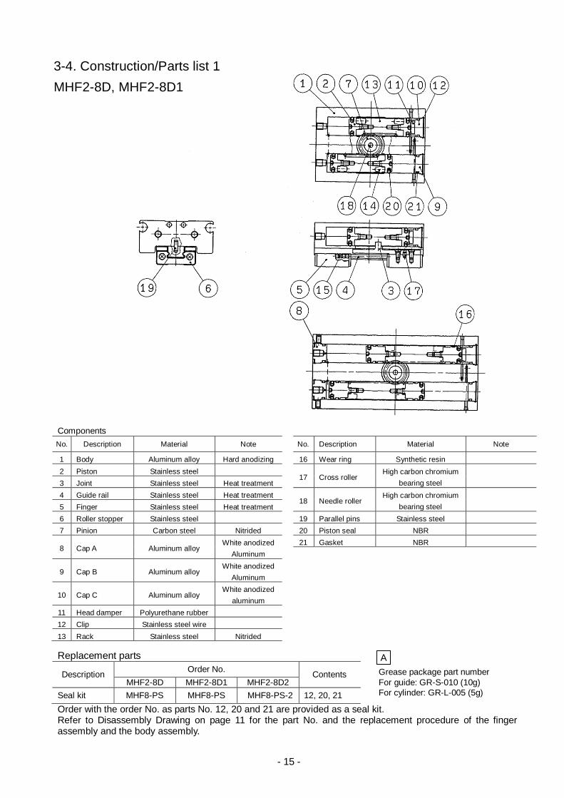
Components
No. Description Material Note No. Description Material Note
1 Body Aluminum alloy Hard anodizing 16 Wear ring Synthetic resin
2 Piston Stainless steel 17 Cross roller
High carbon chromium
bearing steel
3 Joint Stainless steel Heat treatment
4 Guide rail Stainless steel Heat treatment 18 Needle roller
High carbon chromium
bearing steel
5 Finger Stainless steel Heat treatment
6 Roller stopper Stainless steel 19 Parallel pins Stainless steel
7 Pinion Carbon steel Nitrided 20 Piston seal NBR
8 Cap A Aluminum alloy White anodized
Aluminum
21 Gasket NBR
9 Cap B Aluminum alloy White anodized
Aluminum
10 Cap C Aluminum alloy White anodized
aluminum
11 Head damper Polyurethane rubber
12 Clip Stainless steel wire
13 Rack Stainless steel Nitrided
3-4. Construction/Parts list 1
MHF2-8D, MHF2-8D1
Replacement parts
Description Order No.
Contents
Grease package part number
MHF2-8D MHF2-8D1 MHF2-8D2 For guide: GR-S-010 (10g)
Seal kit MHF8-PS MHF8-PS MHF8-PS-2 12, 20, 21 For cylinder: GR-L-005 (5g)
Order with the order No. as parts No. 12, 20 and 21 are provided as a seal kit. Refer to Disassembly Drawing on page 11 for the part No. and the replacement procedure of the finger assembly and the body assembly.
A

- 16 -
Components
No. Description Material Note No. Description Material Note
1 Body Aluminum alloy Hard anodizing
16 12: Cross roller
High carbon chromium
bearing steel
2 Piston Aluminum alloy White anodized aluminum
3 Joint Stainless steel Heat treatment 16 to 20: Parallel pin Stainless steel
4 Guide rail Stainless steel Heat treatment 17 Needle roller
High carbon chromium
bearing steel
5 Finger Stainless steel Heat treatment
6 Roller stopper Stainless steel
18
12: R-shaped
retaining ringCarbon steel Phosphate coated
7 Pinion Carbon steel Nitrided
8 Cap A Aluminum alloy White anodized aluminum 16 to 20: C-shaped
retaining ring 9 Cap B Aluminum alloy White anodized aluminum
10 Cap C Aluminum alloy White anodized aluminum 19 Parallel pin Stainless steel
11 Head damper Polyurethane rubber 20 Piston seal NBR
12 Rack Stainless steel Nitrided 21 Gasket NBR
13 Magnet Rare-earth magnet Nickel plated 22 Gasket NBR
14 Steel ball High carbon chromium
bearing steel
15 Wear ring Synthetic resin
Replacement parts
Description Order No.
Contents
MHF2-12D MHF2-12D1 MHF2-12D2 Grease package part number
Seal kit MHF12-PS MHF12-PS MHF12-PS 20, 21, 22 MHF2-D,D1 (12, 16, 20) GR-S-010 (10g) for guide
MHF2-D2 (12) GR-L-005 (5g) for cylinder
Description Order No.
Contents
MHF2-D2 (16, 20) GR-S-010 (10g) for guide
MHF2-16D MHF2-16D1 MHF2-16D2 GR-L-010 (10g) for cylinder
Seal kit MHF16-PS MHF16-PS MHF16-PS 20, 21, 22
Description Order No.
Contents
MHF2-20D MH2-20D1 MHF2-1D2 Seal kit MHF20-PS MHF20-PS MHF20-PS 20, 21, 22
Order with the order No. according to the cylinder bore as parts No. 20, 21, and 22 are provided as a seal kit. Refer to Disassembly Drawing on page 12 for the part No. and the replacement procedure of the finger assembly and the body assembly.
Construction/Parts list 2
MHF2-12D to 20D
A
A

Revision history
4-14-1, Sotokanda, Chiyoda-ku, Tokyo 101-0021 JAPAN Tel: + 81 3 5207 8249 Fax: +81 3 5298 5362 URL http://www.smcworld.com Note: Specifications are subject to change without prior notice and any obligation on the part of the manufacturer.
© 2015 SMC Corporation All Rights Reserved