
Author : Ps . Desireé Salazar; Co- authors : Ps . Patricia Salazar; Ps . Álvaro García;
Upload
adikurniawan028Category
view
227download
0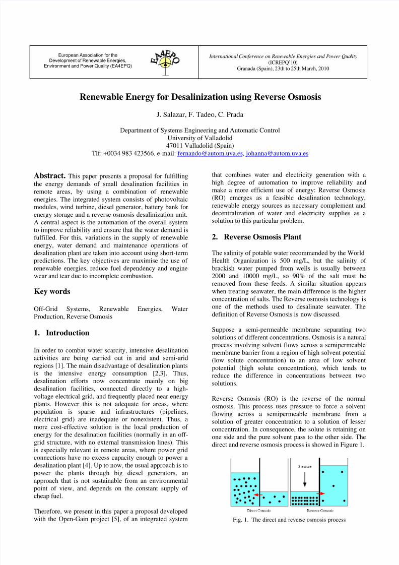
7/31/2019 631 Salazar
http://slidepdf.com/reader/full/631-salazar 1/6
European Association for theDevelopment of Renewable Energies,
Environment and Power Quality (EA4EPQ)
International Conference on Renewable Energies and Power Quality
(ICREPQ’10)Granada (Spain), 23th to 25th March, 2010
Renewable Energy for Desalinization using Reverse Osmosis
J. Salazar, F. Tadeo, C. Prada
Department of Systems Engineering and Automatic Control
University of Valladolid47011 Valladolid (Spain)
Tlf: +0034 983 423566, e-mail: [email protected], [email protected]
Abstract. This paper presents a proposal for fulfilling
the energy demands of small desalination facilities in
remote areas, by using a combination of renewable
energies. The integrated system consists of photovoltaicmodules, wind turbine, diesel generator, battery bank for
energy storage and a reverse osmosis desalinization unit.
A central aspect is the automation of the overall system
to improve reliability and ensure that the water demand is
fulfilled. For this, variations in the supply of renewable
energy, water demand and maintenance operations of
desalination plant are taken into account using short-term
predictions. The key objectives are maximise the use of
renewable energies, reduce fuel dependency and engine
wear and tear due to incomplete combustion.
Key words
Off-Grid Systems, Renewable Energies, Water
Production, Reverse Osmosis
1. Introduction
In order to combat water scarcity, intensive desalination
activities are being carried out in arid and semi-arid
regions [1]. The main disadvantage of desalination plants
is the intensive energy consumption [2,3]. Thus,
desalination efforts now concentrate mainly on big
desalination facilities, connected directly to a high-
voltage electrical grid, and frequently placed near energyplants. However this is not adequate for areas, where
population is sparse and infrastructures (pipelines,
electrical grid) are inadequate or nonexistent. Thus, a
more cost-effective solution is the local production of
energy for the desalination facilities (normally in an off-
grid structure, with no external transmission lines). This
is especially relevant in remote areas, where power grid
connections have no excess capacity enough to power a
desalination plant [4]. Up to now, the usual approach is to
power the plants through big diesel generators, an
approach that is not sustainable from an environmental
point of view, and depends on the constant supply of
cheap fuel.
Therefore, we present in this paper a proposal developed
with the Open-Gain project [5], of an integrated system
that combines water and electricity generation with a
high degree of automation to improve reliability and
make a more efficient use of energy: Reverse Osmosis
(RO) emerges as a feasible desalination technology,renewable energy sources as necessary complement and
decentralization of water and electricity supplies as asolution to this particular problem.
2. Reverse Osmosis Plant
The salinity of potable water recommended by the World
Health Organization is 500 mg/L, but the salinity of
brackish water pumped from wells is usually between
2000 and 10000 mg/L, so 90% of the salt must be
removed from these feeds. A similar situation appears
when treating seawater, the main difference is the higher
concentration of salts. The Reverse osmosis technology isone of the methods used to desalinate seawater. The
definition of Reverse Osmosis is now discussed.
Suppose a semi-permeable membrane separating two
solutions of different concentrations. Osmosis is a natural
process involving solvent flows across a semipermeable
membrane barrier from a region of high solvent potential
(low solute concentration) to an area of low solvent
potential (high solute concentration), which tends to
reduce the difference in concentrations between two
solutions.
Reverse Osmosis (RO) is the reverse of the normalosmosis. This process uses pressure to force a solvent
flowing across a semipermeable membrane from a
solution of greater concentration to a solution of lesser
concentration. In consequence, the solute is retaining on
one side and the pure solvent pass to the other side. The
direct and reverse osmosis process is showed in Figure 1.
Fig. 1. The direct and reverse osmosis process
7/31/2019 631 Salazar
http://slidepdf.com/reader/full/631-salazar 2/6
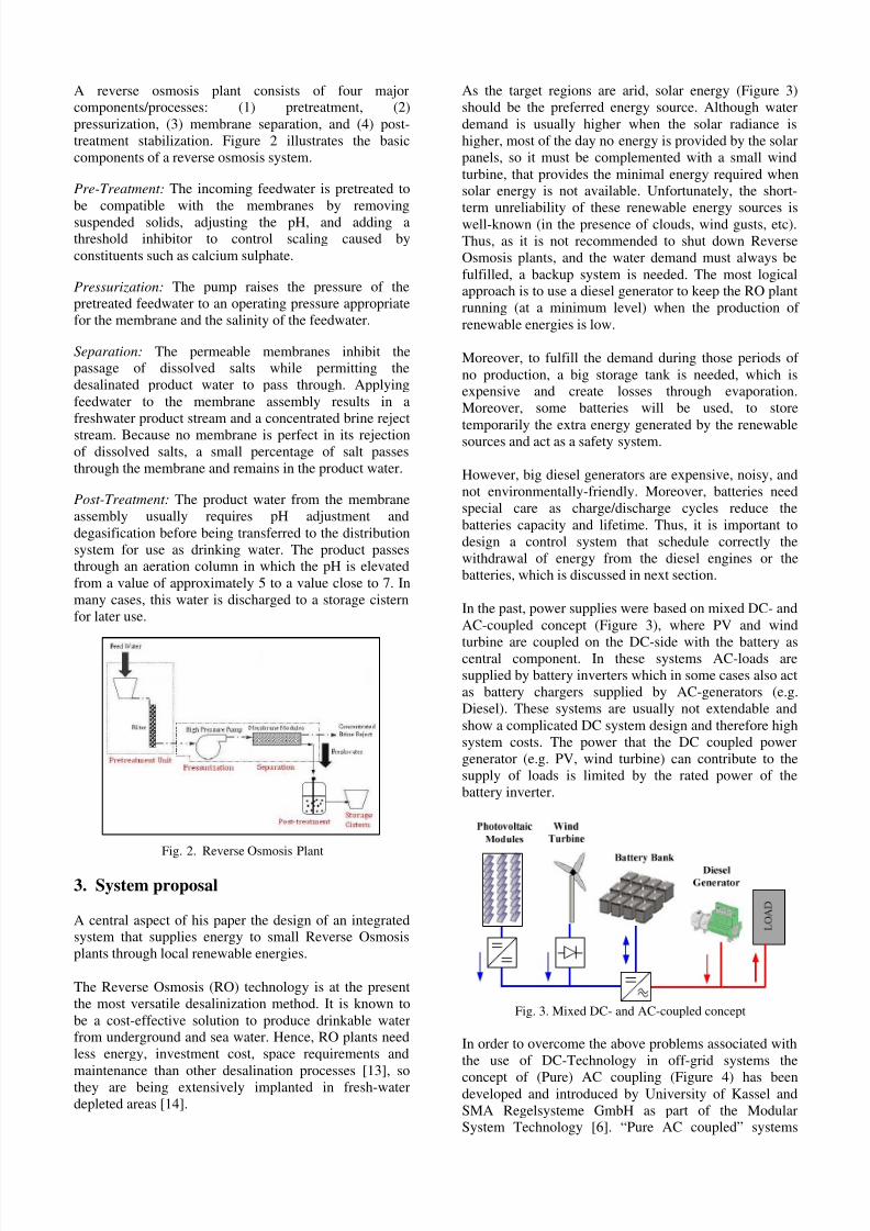
A reverse osmosis plant consists of four majorcomponents/processes: (1) pretreatment, (2)
pressurization, (3) membrane separation, and (4) post-
treatment stabilization. Figure 2 illustrates the basic
components of a reverse osmosis system.
Pre-Treatment: The incoming feedwater is pretreated to
be compatible with the membranes by removing
suspended solids, adjusting the pH, and adding athreshold inhibitor to control scaling caused by
constituents such as calcium sulphate.
Pressurization: The pump raises the pressure of the
pretreated feedwater to an operating pressure appropriate
for the membrane and the salinity of the feedwater.
Separation: The permeable membranes inhibit thepassage of dissolved salts while permitting the
desalinated product water to pass through. Applying
feedwater to the membrane assembly results in a
freshwater product stream and a concentrated brine reject
stream. Because no membrane is perfect in its rejectionof dissolved salts, a small percentage of salt passes
through the membrane and remains in the product water.
Post-Treatment: The product water from the membrane
assembly usually requires pH adjustment and
degasification before being transferred to the distribution
system for use as drinking water. The product passesthrough an aeration column in which the pH is elevated
from a value of approximately 5 to a value close to 7. In
many cases, this water is discharged to a storage cistern
for later use.
Fig. 2. Reverse Osmosis Plant
3. System proposal
A central aspect of his paper the design of an integratedsystem that supplies energy to small Reverse Osmosis
plants through local renewable energies.
The Reverse Osmosis (RO) technology is at the present
the most versatile desalinization method. It is known to
be a cost-effective solution to produce drinkable waterfrom underground and sea water. Hence, RO plants need
less energy, investment cost, space requirements and
maintenance than other desalination processes [13], so
they are being extensively implanted in fresh-water
depleted areas [14].
As the target regions are arid, solar energy (Figure 3)
should be the preferred energy source. Although water
demand is usually higher when the solar radiance is
higher, most of the day no energy is provided by the solar
panels, so it must be complemented with a small wind
turbine, that provides the minimal energy required whensolar energy is not available. Unfortunately, the short-
term unreliability of these renewable energy sources is
well-known (in the presence of clouds, wind gusts, etc).
Thus, as it is not recommended to shut down Reverse
Osmosis plants, and the water demand must always be
fulfilled, a backup system is needed. The most logicalapproach is to use a diesel generator to keep the RO plant
running (at a minimum level) when the production of
renewable energies is low.
Moreover, to fulfill the demand during those periods of
no production, a big storage tank is needed, which isexpensive and create losses through evaporation.
Moreover, some batteries will be used, to store
temporarily the extra energy generated by the renewablesources and act as a safety system.
However, big diesel generators are expensive, noisy, and
not environmentally-friendly. Moreover, batteries need
special care as charge/discharge cycles reduce the
batteries capacity and lifetime. Thus, it is important to
design a control system that schedule correctly the
withdrawal of energy from the diesel engines or the
batteries, which is discussed in next section.
In the past, power supplies were based on mixed DC- and
AC-coupled concept (Figure 3), where PV and wind
turbine are coupled on the DC-side with the battery ascentral component. In these systems AC-loads are
supplied by battery inverters which in some cases also act
as battery chargers supplied by AC-generators (e.g.
Diesel). These systems are usually not extendable and
show a complicated DC system design and therefore high
system costs. The power that the DC coupled power
generator (e.g. PV, wind turbine) can contribute to the
supply of loads is limited by the rated power of the
battery inverter.
Fig. 3. Mixed DC- and AC-coupled concept
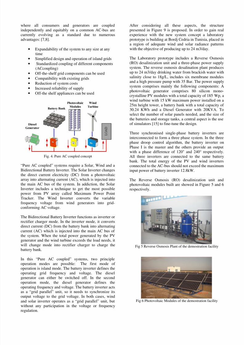
In order to overcome the above problems associated with
the use of DC-Technology in off-grid systems the
concept of (Pure) AC coupling (Figure 4) has beendeveloped and introduced by University of Kassel and
SMA Regelsysteme GmbH as part of the ModularSystem Technology [6]. “Pure AC coupled” systems
7/31/2019 631 Salazar
http://slidepdf.com/reader/full/631-salazar 3/6
where all consumers and generators are coupled
independently and equitably on a common AC-bus are
currently evolving as a standard due to numerous
advantages: [7,8].
• Expandability of the system to any size at any
time
•
Simplified design and operation of island grids• Standardized coupling of different components
(ACcoupling)
• Off-the-shelf grid components can be used
• Compatibility with existing grids
• Reduction of system costs
• Increased reliability of supply
• Off-the shelf appliances can be used
Fig. 4. Pure AC coupled concept
“Pure AC coupled” systems require a Solar, Wind and a
Bidirectional Battery Inverter. The Solar Inverter changes
the direct current electricity (DC) from a photovoltaic
array into alternating current (AC), which is injected intothe main AC bus of the system. In addiction, the Solar
Inverter includes a technique to get the most possible
power from PV array called Maximum Power Point
Tracker. The Wind Inverter converts the variable
frequency voltage from wind generators into grid-
conforming AC voltage.
The Bidirectional Battery Inverter functions as inverter or
rectifier charger mode. In the inverter mode, it converts
direct current (DC) from the battery bank into alternating
current (AC) which is injected into the main AC bus of
the system. When the total power generated by the PV
generator and the wind turbine exceeds the load needs, itwill change mode into rectifier charger to charge the
battery bank.
In this “Pure AC coupled” systems, two principle
operation modes are possible: The first mode of operation is island mode. The battery inverter defines the
operating grid frequency and voltage. The diesel
generator can either be switched off. In the second
operation mode, the diesel generator defines the
operating frequency and voltage. The battery inverter actsas a “grid parallel” unit, so it needs to synchronize its
output voltage to the grid voltage. In both cases, wind
and solar inverter operates as a “grid parallel” unit, butwithout any participation in the voltage or frequency
regulation.
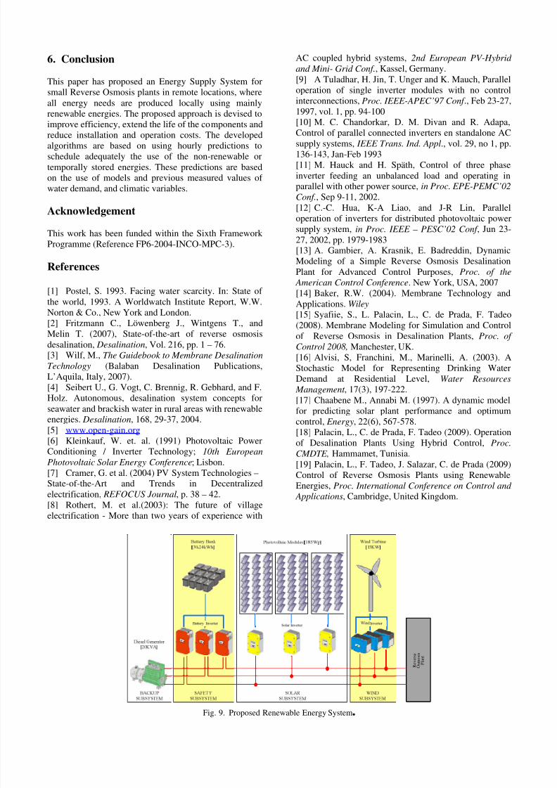
After considering all these aspects, the structure
presented in Figure 9 is proposed. In order to gain real
experience with the new system concept a laboratory
prototype is building at Bordj Cedria in Tunisia, placed in
a region of adequate wind and solar radiance patterns
with the objective of producing up to 24 m3/day.
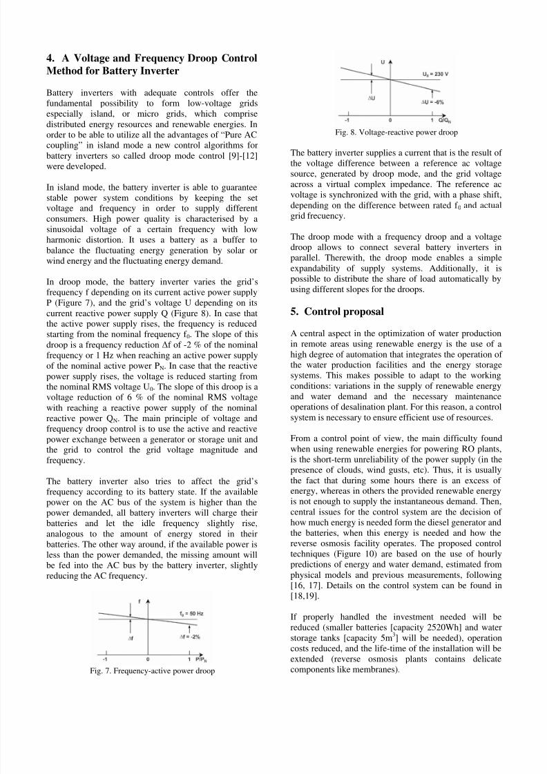
The Laboratory prototype includes a Reverse Osmosis
(RO) desalinization unit and a three-phase power supply
system. The reverse osmosis desalination plant produces
up to 24 m3/day drinking water from brackish water with
salinity close to 18g/L, includes six membrane modulesand a high pressure pump with 35 Bar. The power supply
system comprises mainly the following components: A
photovoltaic generator comprises 80 silicon mono-
crystalline PV modules with a total capacity of 185 Wp, a
wind turbine with 15 kW maximum power installed on a
25m height tower, a battery bank with a total capacity of 30.24 KWh and a Diesel Generator with 20KVA. To
select the number of solar panels needed, and the size of
the batteries and storage tanks, a central aspect is the useof simulators [15] to fine-tune the design.
Three synchronised single-phase battery inverters are
interconnected to form a three phase system. In the three
phase droop control algorithm, the battery inverter on
Phase I is the master and the others provide an output
with a phase difference of 120" and 240° respectively.
All three inverters are connected to the same battery
bank. The total energy of the PV and wind inverters
connected to the AC-bus should not exceed the maximum
input power of battery inverter 12.8kW.
The Reverse Osmosis (RO) desalinization unit andphotovoltaic modules built are showed in Figure 5 and 6
respectively.
Fig 5 Reverse Osmosis Plant of the demostration facility
Fig 6 Photovoltaic Modules of the demostration facility
7/31/2019 631 Salazar
http://slidepdf.com/reader/full/631-salazar 4/6
4. A Voltage and Frequency Droop Control
Method for Battery Inverter
Battery inverters with adequate controls offer the
fundamental possibility to form low-voltage grids
especially island, or micro grids, which comprise
distributed energy resources and renewable energies. In
order to be able to utilize all the advantages of “Pure ACcoupling” in island mode a new control algorithms for
battery inverters so called droop mode control [9]-[12]
were developed.
In island mode, the battery inverter is able to guarantee
stable power system conditions by keeping the setvoltage and frequency in order to supply different
consumers. High power quality is characterised by a
sinusoidal voltage of a certain frequency with low
harmonic distortion. It uses a battery as a buffer to
balance the fluctuating energy generation by solar or
wind energy and the fluctuating energy demand.
In droop mode, the battery inverter varies the grid’s
frequency f depending on its current active power supply
P (Figure 7), and the grid’s voltage U depending on its
current reactive power supply Q (Figure 8). In case thatthe active power supply rises, the frequency is reduced
starting from the nominal frequency f 0. The slope of this
droop is a frequency reduction ∆f of -2 % of the nominal
frequency or 1 Hz when reaching an active power supply
of the nominal active power PN. In case that the reactive
power supply rises, the voltage is reduced starting fromthe nominal RMS voltage U0. The slope of this droop is a
voltage reduction of 6 % of the nominal RMS voltage
with reaching a reactive power supply of the nominalreactive power QN. The main principle of voltage and
frequency droop control is to use the active and reactive
power exchange between a generator or storage unit andthe grid to control the grid voltage magnitude and
frequency.
The battery inverter also tries to affect the grid’s
frequency according to its battery state. If the available
power on the AC bus of the system is higher than the
power demanded, all battery inverters will charge their
batteries and let the idle frequency slightly rise,
analogous to the amount of energy stored in their
batteries. The other way around, if the available power isless than the power demanded, the missing amount will
be fed into the AC bus by the battery inverter, slightly
reducing the AC frequency.
Fig. 7. Frequency-active power droop
Fig. 8. Voltage-reactive power droop
The battery inverter supplies a current that is the result of
the voltage difference between a reference ac voltage
source, generated by droop mode, and the grid voltage
across a virtual complex impedance. The reference ac
voltage is synchronized with the grid, with a phase shift,
depending on the difference between rated f 0 and actual
grid frecuency.
The droop mode with a frequency droop and a voltage
droop allows to connect several battery inverters in
parallel. Therewith, the droop mode enables a simple
expandability of supply systems. Additionally, it ispossible to distribute the share of load automatically by
using different slopes for the droops.
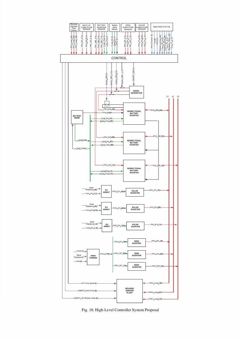
5. Control proposal
A central aspect in the optimization of water production
in remote areas using renewable energy is the use of a
high degree of automation that integrates the operation of the water production facilities and the energy storage
systems. This makes possible to adapt to the working
conditions: variations in the supply of renewable energy
and water demand and the necessary maintenance
operations of desalination plant. For this reason, a controlsystem is necessary to ensure efficient use of resources.
From a control point of view, the main difficulty found
when using renewable energies for powering RO plants,
is the short-term unreliability of the power supply (in the
presence of clouds, wind gusts, etc). Thus, it is usually
the fact that during some hours there is an excess of energy, whereas in others the provided renewable energy
is not enough to supply the instantaneous demand. Then,
central issues for the control system are the decision of
how much energy is needed form the diesel generator and
the batteries, when this energy is needed and how the
reverse osmosis facility operates. The proposed controltechniques (Figure 10) are based on the use of hourly
predictions of energy and water demand, estimated from
physical models and previous measurements, following
[16, 17]. Details on the control system can be found in
[18,19].
If properly handled the investment needed will be
reduced (smaller batteries [capacity 2520Wh] and water
storage tanks [capacity 5m3] will be needed), operation
costs reduced, and the life-time of the installation will be
extended (reverse osmosis plants contains delicate
components like membranes).
7/31/2019 631 Salazar
http://slidepdf.com/reader/full/631-salazar 5/6
7/31/2019 631 Salazar
http://slidepdf.com/reader/full/631-salazar 6/6
Fig. 10. High-Level Controller System Proposal