611 DL/DLD/DLM PGS 239-256 - PEI-Genesis · AWG Lbs. 32 1 30 1.5 28 3 26 10 24 15 22 15 20 19 18 30...
18
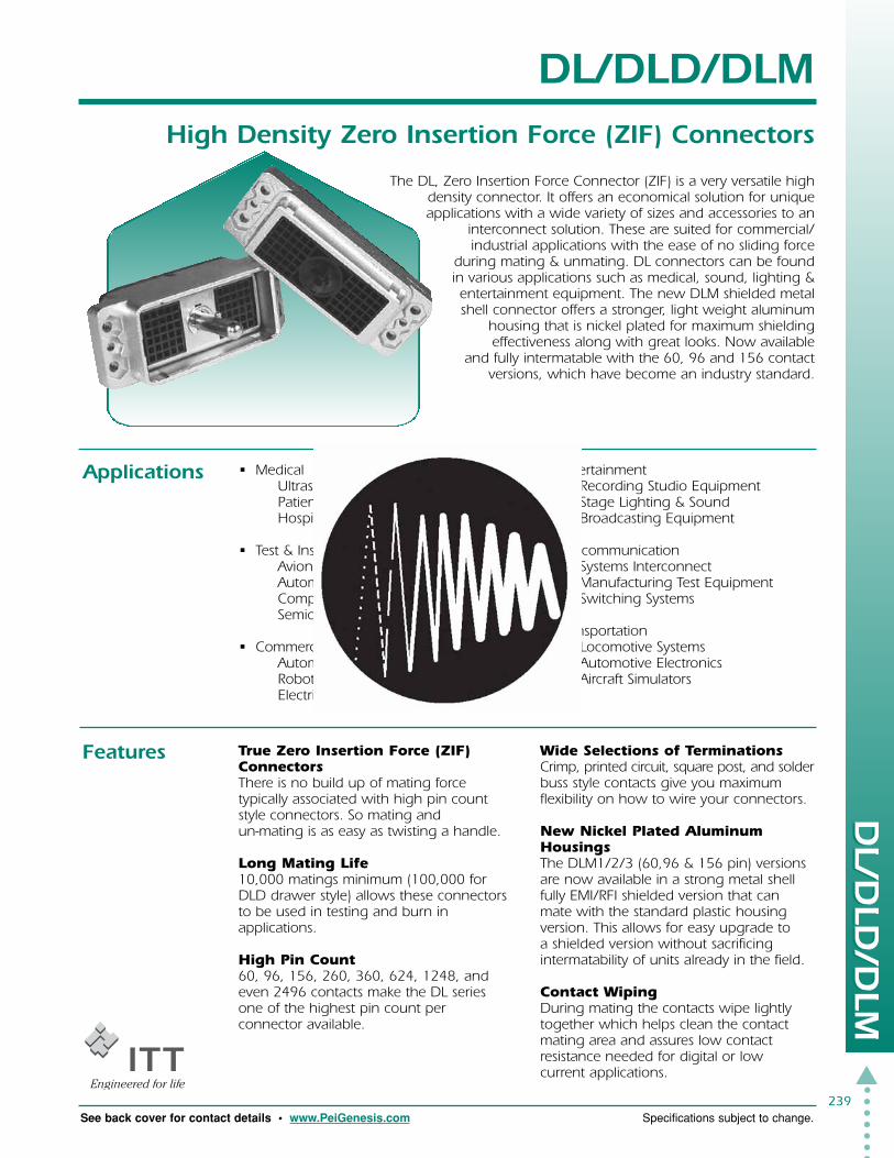
239 DL/DLD/DLM High Density Zero Insertion Force (ZIF) Connectors ▲ DL/DLD/DLM DL/DLD/DLM DL/DLD/DLM See back cover for contact details • www.PeiGenesis.com Specifications subject to change. The DL, Zero Insertion Force Connector (ZIF) is a very versatile high density connector. It offers an economical solution for unique applications with a wide variety of sizes and accessories to an interconnect solution. These are suited for commercial/ industrial applications with the ease of no sliding force during mating & unmating. DL connectors can be found in various applications such as medical, sound, lighting & entertainment equipment. The new DLM shielded metal shell connector offers a stronger, light weight aluminum housing that is nickel plated for maximum shielding effectiveness along with great looks. Now available and fully intermatable with the 60, 96 and 156 contact versions, which have become an industry standard. Applications Features • Medical Ultrasound Diagnostic Patient Monitoring Hospital Equipment • Test & Instrumentation Avionics Automated Test Equipment Computer & Peripheral Equipment Semiconductor • Commercial/Industrial Manufacturing Automation Robotics Electrical Controls • Entertainment Recording Studio Equipment Stage Lighting & Sound Broadcasting Equipment • Telecommunication Systems Interconnect Manufacturing Test Equipment Switching Systems • Transportation Locomotive Systems Automotive Electronics Aircraft Simulators True Zero Insertion Force (ZIF) Connectors There is no build up of mating force typically associated with high pin count style connectors. So mating and un-mating is as easy as twisting a handle. Long Mating Life 10,000 matings minimum (100,000 for DLD drawer style) allows these connectors to be used in testing and burn in applications. High Pin Count 60, 96, 156, 260, 360, 624, 1248, and even 2496 contacts make the DL series one of the highest pin count per connector available. Wide Selections of Terminations Crimp, printed circuit, square post, and solder buss style contacts give you maximum flexibility on how to wire your connectors. New Nickel Plated Aluminum Housings The DLM1/2/3 (60,96 & 156 pin) versions are now available in a strong metal shell fully EMI/RFI shielded version that can mate with the standard plastic housing version. This allows for easy upgrade to a shielded version without sacrificing intermatability of units already in the field. Contact Wiping During mating the contacts wipe lightly together which helps clean the contact mating area and assures low contact resistance needed for digital or low current applications.
Transcript of 611 DL/DLD/DLM PGS 239-256 - PEI-Genesis · AWG Lbs. 32 1 30 1.5 28 3 26 10 24 15 22 15 20 19 18 30...
239
DL/DLD/DLMHigh Density Zero Insertion Force (ZIF) Connectors
�
DL/DLD/DLM
DL/DLD/DLM
DL/DLD/DLM
See back cover for contact details • www.PeiGenesis.com Specifications subject to change.
The DL, Zero Insertion Force Connector (ZIF) is a very versatile highdensity connector. It offers an economical solution for uniqueapplications with a wide variety of sizes and accessories to an
interconnect solution. These are suited for commercial/industrial applications with the ease of no sliding force
during mating & unmating. DL connectors can be foundin various applications such as medical, sound, lighting &entertainment equipment. The new DLM shielded metalshell connector offers a stronger, light weight aluminum
housing that is nickel plated for maximum shieldingeffectiveness along with great looks. Now available
and fully intermatable with the 60, 96 and 156 contactversions, which have become an industry standard.
Applications
Features
• MedicalUltrasound DiagnosticPatient MonitoringHospital Equipment
• Test & InstrumentationAvionicsAutomated Test EquipmentComputer & Peripheral EquipmentSemiconductor
• Commercial/Industrial ManufacturingAutomationRoboticsElectrical Controls
• EntertainmentRecording Studio EquipmentStage Lighting & SoundBroadcasting Equipment
• TelecommunicationSystems InterconnectManufacturing Test EquipmentSwitching Systems
• TransportationLocomotive SystemsAutomotive ElectronicsAircraft Simulators
True Zero Insertion Force (ZIF)ConnectorsThere is no build up of mating forcetypically associated with high pin countstyle connectors. So mating andun-mating is as easy as twisting a handle.
Long Mating Life10,000 matings minimum (100,000 forDLD drawer style) allows these connectorsto be used in testing and burn inapplications.
High Pin Count60, 96, 156, 260, 360, 624, 1248, andeven 2496 contacts make the DL seriesone of the highest pin count perconnector available.
Wide Selections of TerminationsCrimp, printed circuit, square post, and solderbuss style contacts give you maximumflexibility on how to wire your connectors.
New Nickel Plated AluminumHousingsThe DLM1/2/3 (60,96 & 156 pin) versionsare now available in a strong metal shellfully EMI/RFI shielded version that canmate with the standard plastic housingversion. This allows for easy upgrade toa shielded version without sacrificingintermatability of units already in the field.
Contact WipingDuring mating the contacts wipe lightlytogether which helps clean the contactmating area and assures low contactresistance needed for digital or lowcurrent applications.

�240
TechnicalSpecifications
DL/DLD/DLM
DL/DLD/DLM
See back cover for contact details • www.PeiGenesis.com Specifications subject to change.
DL1DLM1DLD1
DL3DLM3
DL4
MATERIALS & FINISHESShells DL1/2/3 Glass filled thermoplastic, UL94V1 rated, Color: Black
DL4 Aluminum alloy, cadmium plated housing, clear anodizedmounting plate
DL5 Glass filled thermoplastic, UL94V0 rated, Color: BlackDLD1/2 Glass filled thermoplastic, UL94V1 rated, Color: BlackDLM1/2/3/5/6 Aluminum alloy, nickel plated
Actuators & Plug insert retainers Stainless steel, passivatedSpring Mounting Screws (DLD) Stainless steel, passivatedCompression Spring (DLD) Music wire, zinc platedContacts Copper alloyPlating
Crimp 50µ inches gold over 50µ inches nickel mating area gold flash on balanceCrimp 20µ inches gold over 50µ inches nickel mating area tin lead on balanceSquare Post 50µ inches gold over 50µ inches nickel mating area gold flash on balanceSquare Post 20µ inches gold over 50µ inches nickel mating area gold flash on balancePC/RC 20µ inches gold over 50µ inches nickel mating area tin lead on balance
InsulatorsDL4 Glass filled thermoplastic, UL94V1 rated, Color: GreyDLM1/2/3/5/6 Glass filled thermoplastic, UL94V0 rated, Color: Black
ELECTRICALDielectric Withstanding Voltage 1200 Vac RMS – Crimp & square post contacts
1000 Vac RMS – PC/RC round PCB contacts750 Vac RMS – DL4
Current Rating 5 Amps maximum – Crimp & square post contacts4 Amps maximum – PC/RC contact10 Amps up to 60 Amps maximum for buss contacts
Note: The Ambient Temperature Curves shown represent the rated current carrying capacity of the CannonDL1/2/3/4, DLM1/2/3, and DLD1/2 electrical connectors, derated to 80% of the value recorded usingthe methods specified by International Electro-Technical Commission Document 48 (1975).Current was applied to the total connector (all contacts) in one-half ampere increments and maintainedat each current level until thermal stability was achieved. A thermocouple inserted into the “hottestarea” of each connector then measured the connector temperature at the same time that an ambienttemperature reading was taken. The difference between the two measured values is the heat rise orself-heating created solely by the current flow, and this temperature rise for the current level wasdeducted from the insulator material rated temperature. These values were then derated to 80%to obtain the curves shown.
Wire Range Sizes 32 AWG –18 AWGContact Resistance 15 milliohms maximum – Crimp & square post contacts
20 milliohms maximum – Crimp 32-30 AWG contacts30 milliohms maximum – PC/RC contacts
Insulation Resistance 5000 megohms minimum
DL2DLM2DLD2

AWG Lbs.32 130 1.528 326 1024 1522 1520 1918 30
241
�
TechnicalSpecifications
DL/DLD/DLM
DL/DLD/DLM
See back cover for contact details • www.PeiGenesis.com Specifications subject to change.
MECHANICALOperating Temperature -55°C to 105°C: DL4 -55°C to 71°CDurability 10,000 Mating cycles minimum DL/DLM
20,000 Mating cycles minimum DL4100,000 Mating cycles minimum DLD
Insulation Strip Length 32 to 22 AWG .130" (3.30mm)20 to 18 AWG .160" (4.06mm)
Insulation Diameter 30 to 28 AWG .053 (1.35mm) maximum26 to 24 AWG .065 (1.65mm) maximum22 to 18 AWG .074 (1.88mm) maximum
Crimp Tensile Strength min. lbs.
Chemical Resistance Salt spray per MIL-STD-202 method 101 Condition B (48 hours)Vibration Per MIL-STD-202 method 204 Condition C
Per MIL-STD-167-1/2 Modified (DL4)Shock Per MIL-STD-202 method 213 Condition A (50g’s)Contact Type Crimp, wire wrap, printed circuit board,
Bus contacts -solder or crimp lug tabNumber of Circuits 60-2496Contact Insertion Hand insertable from rear no insertion tool requiredContact Retention 8 lbs. (35.585 newtons) minimumContact Spacing .100" (25.4mm) square gridPolarization By center and/or corner polarizing post kitApprovals UL94V1 and UL94V0 materials
How DL/DLMHand ActuatedConnectorsWork
How DLDDrawer StyleConnectorsWork

�242
How To Order DL/DLM
DL/DLD/DLM
DL/DLD/DLM
See back cover for contact details • www.PeiGenesis.com Specifications subject to change.
Plugs
Receptacles
PC Tail Round .280"PC Tail .280" (7.11mm) Square .025 (.64mm) (7.11mm) dia.020 (.50mm)
Number of Non Shielded ShieldedContacts 50µ" Gold 20µ" Gold 50µ" Gold 20µ" Gold 20µ" Gold
60 - Call DLM3-60PW6A DLM3-60PW6 DLM3-60PC112138-0000 112138-0001 127050-0223
96 DL2-96PW6A Call DLM2-96PW6A DLM2-96PW6 DLM2-96PC110777-0025 112136-0000 112136-0001 127050-0215
156 DL1-156PW6A DL1-156PW6 DLM1-156PW6A DLM1-156PW6 DLM1-156PC110535-0030 110535-0026 112134-0000 112134-0001 127050-0207
260 DL5-260PW6A Call DLM5-260PW6A DLM5-260PW6 DLM5-260PC111986-0000 112086-0000 112086-0002 127050-0111
360 Call Call DLM6-360PW6A DLM6-360PW6 DLM6-360PC111995-0000 111995-0001 127050-0097
624 DL4-624PW6A Call - - -110959-0042
1248 Call Call - - -
2496 Call Call - - -
PC Tail Round .280"PC Tail .280" (7.11mm) Square .025 (.64mm) (7.11mm) dia.020 (.50mm)
Number of Non Shielded ShieldedContacts 50µ" Gold 20µ" Gold 50µ" Gold 20µ" Gold 20µ" Gold
60 DL3-60RW6B Call DLM3-60RW6B - DLM3-60RC110901-0010 112139-0000 127050-0227
96 DL2-96RW6B Call DLM2-96RW6B - DLM2-96RC110855-0014 112137-0000 127050-0366
156 DL1-156RW6B DL1-156RW6 DLM1-156RW6B - DLM1-156RC110536-1007 110536-1009 112135-0000 127050-0211
260 DL5-260RW6B Call DLM5-260RW6B - DLM5-260RC111987-0000 112087-0000 127050-0112
360 Call Call DLM6-360RW6B - DLM6-360RC111996-0001 127050-0098
624 DL4-624RW6B Call - - -110960-0048
1248 Call Call - - -
2496 Call Call - - -

243
How To Order DL/DLM
�
DL/DLD/DLM
DL/DLD/DLM
See back cover for contact details • www.PeiGenesis.com Specifications subject to change.
PC Wire Wrap/PC Tail .605" (15.37 mm) PC Wire Wrap/Tail Length .125" (3.18mm) For Crimp andSquare .025 (.64mm) Square .025 (.64mm) Insert Contacts
Non Shielded Shielded 50 Non Shielded 50 Shielded 50 Non Shielded Shielded50µ" Gold 20µ" Gold 50µ" Gold 50µ" Gold 50µ" Gold
DL3-60PW4A DL3-60PW4 DLM3-60PW4A Call DLM3-60P w/.125 DL3-60P DLM3-60P110900-0013 110900-0006 112138-0001 112138-0002 110900-0008 127050-0220
DL2-96PW4A DL2-96PW4 DLM2-96PW4A Call DLM2-96P w/.125 DL2-96P DLM2-96P110777-0022 110777-0008 112136-0001 112136-0002 110777-0000 127050-0212
DL1-156PW4A DL1-156PW4 DLM1-156PW4A DL1-156P w/.125 DLM1-156P w/.125 DL1-156P DLM1-156P110535-0025 110535-0012 112134-0001 110535-0040 112134-0002 110535-0000 127050-0204
DL5-260PW4A Call DLM5-260PW4A Call DLM5-260P w/.125 DL5-260P DLM5-260P111986-0003 112086-0002 112086-0003 111986-0014 127050-0109
- Call DLM6-360PW4A Call DLM6-360P w/.125 - DLM6-360P111995-0001 111995-0007 127050-0034
DL4-624PW4A DL4-624PW4 - Call - DL4-624P -110959-0035 110959-0011 110959-0002
Call Call - Call - DL4-1248P -110959-0003
Call Call - Call - DL4-2496P -110959-0004
PC Wire Wrap/PC Tail .605" (15.37 mm) PC Wire Wrap /Tail Length .125" (3.18mm) For Crimp andSquare .025 (.64mm) Square .025 (.64mm) Insert Contacts
Non Shielded Shielded Non Shielded Shielded Non Shielded Shielded50µ" Gold 20µ" Gold 50µ" Gold 50µ" Gold 50µ" Gold
DL3-60RW4B DL3-60RW4 DLM3-60RW4B Call DLM3-60R w/.125 DL3-60R DLM3-60R110901-0009 110901-0004 112139-0001 112139-0002 086-0032-000 127050-0224
DL2-96RW4B DL2-96RW4 DLM2-96RW4B Call DLM2-96R w/.125 DL2-96R DLM2-96R110855-0013 110855-0008 112137-0001 112137-0002 086-0031-000 127050-0216
DL1-156RW4B DL1-156RW4 DL1-156RW4B DL1-156R w/.125 DLM1-156R w/.125 DL1-156R DLM1-156R110536-1006 110536-1003 112135-0001 110536-1011 112135-0002 086-0030-000 127050-0208
DL5-260RW4B Call DLM5-260RW4B Call DLM5-260R w/.125 DL5-260R DLM5-260R111987-0001 112087-0001 112087-0003 086-4501-000 127050-0110
- Call DLM6-360RW4B Call DLM6-360R w/.125 - DLM6-360R111996-0000 111996-0005 127050-0045
DL4-624RW4B DL4-624RW4 - Call - DL4-624R -110960-0045 110960-0022 110960-0002
Call Call - Call - DL4-1248R -110960-0003
Call Call - Call - DL4-2496R -110960-0004

�244
How to Order DLD
DL/DLD/DLM
DL/DLD/DLM
See back cover for contact details • www.PeiGenesis.com Specifications subject to change.
Connector Plug Plug Receptacle Metal Max.Style Actuating Protective Protective Backshell Cable
Handles Covers Covers Size
DL/DLM3-60 039-0246-000 039-0247-000 249-4518-000
025-0850-000†
DL/DLM2-96 204-0016-000 039-0244-000 039-0245-000 249-4517-000 .750 (19.05)
025-0851-000†
DL/DLM1-156 039-0242-000 039-0243-000 249-4520-000
025-0852-000†
DL/DLM5-260 204-4501-000 - - 249-4501-000 .875 (22.23)
DL/DLM6-360 204-4500-000 - - 249-4515-000 1.102 (28.00)
DL4-624 - 039-0239-000 039-0240-000 - -
DL4-1248 - 039-0245-000 039-0236-000 - -
Number PC Tail .280" (7.11mm) PC Wire Wrap /PC Tail .605" (15.37mm) For Crimp andof Contacts Square .025 (.64mm) Square .025 (.64mm) Insert Contacts
50 microinches 50 microinches
96 DLD2-96PW6A DLD2-96PW4A DLD2-96P111922-0002 111922-0001 111922-0000
156 DLD1-156PW6A DLD1-156PW4A DLD1-156P111496-0002 111496-0001 111496-0000
Plugs
Receptacles
Number PC Tail .280" (7.11mm) PC Wire Wrap /PC Tail .605" (15.37mm) For Crimp andof Contacts Square .025 (.64mm) Square .025 (.64mm) Insert Contacts
50 microinches 50 microinches
96 DLD2-96RW6B DLD2-96RW4B DLD2-96R111921-0002 111921-0001 111921-0000
156 DLD1-156RW6B DLD1-156RW4B DLD1-156R111497-0010 111497-0009 111497-0004
45
1
76
8
A
5
2
4
3
BCDEFGHJKLMNP
Accessories
†
† Low cost plastic Dimensions are in inches (mm).

PCB Pad Layout
For the PC/RC Versions: The contact tail design has been modified from a 0.64 (.025)square pin to a 0.05 (.020) diameter round pin. The change enables a decrease in thediameter of the through holes as well as the solder mounds on PCB’s (d1, and d2 can bewider than D1 and D2). This can reduce the crosstalk in RF circuits and enhance thedielectric withstanding voltage in high voltage circuits.The soldering of contacts into through (THRU) holes on a PC Board has become standardfor medical equipment and test equipment for semi-conductors. As a result of the narrowspacing between the solder pad and circuit pattern, crosstalk between signals increases.A solution to this problem is to make the diameter of the contacts and solder lands smallerto provide more space between the lands and the patterns. However, a smaller diametercontact results in higher impedance.ITT Cannon designed a solution with a smaller diameter contact tail. This design applicationallows the use of a smaller through-hole diameter.
245
�
DL/DLD/DLM
DL/DLD/DLM
See back cover for contact details • www.PeiGenesis.com Specifications subject to change.
Cable Clamp forPlastic second entry in Max Cable Corner Center
Backshell Plastic Backshell Size (Note: post replaces nut)
249-2060-000 218-0180-000 .560(14.20mm)249-2237-000 218-0181-000 .625(15.90mm) -249-2237-001 218-0200-000 .875(22.23mm)249-2060-001 218-0181-000 .625(15.90mm) 45° 320-0021-006 DL
320-4505-000 DLM249-1985-000 218-0180-000 .560(14.20mm)249-2238-000 218-0181-000 .625(15.90mm)249-2238-001 218-0200-000 .875(22.23mm)249-1985-001 218-0181-000 .625(15.90mm) 45° 320-0021-005
249-1950-000 218-0179-000 .875(22.23mm) 320-0021-006 DL
- - - 320-4502-000 -
- - - 320-0021-006 -
- - - - -
- - - - -
Printed Circuit Contacts
CONTACT
SOLDERTHRU HOLE
PC TAIL
PCB
CONNECTORINSULATOR
Dimensions
D1 1.14(.045)D2 0.47(.018)d1 1.44(.057)d2 0.82(.024)
Accessories
Polarizing Posts
�
�
� 45 Degree Cable Entry Dimensions are in inches (mm).

Wire Plating Wire Maximum Hand ExtractionSize Mating Area Strip Insulation Crimp ToolAWG Balance Length Diameter Tool
of contact Loose 10,000 Piece Loose 10,000 PieceReel* Reel*
50µ" Gold- 030-2416-003 110238-0482 030-2494-001 110238-0486Gold Flash
28-32 112108-000220µ" Gold- 030-2416-001 110238-0403 - -Tin Lead .130 .053
(3.30) (1.35)50µ" Gold- 030-2410-003 110238-0480 030-2492-001 110238-0484 274-7029-007Gold Flash
24-2620µ" Gold- 030-2410-001 110238-0401 - -Tin Lead
112108-000150µ" Gold- 030-2409-003 110238-0479 030-2491-001 110238-0483Gold Flash
20-2220µ" Gold- 030-2409-001 110238-0400 - -Tin Lead .160 .074
(4.06) (1.88)50µ" Gold- 030-2415-003 110238-0481 030-2493-001 110238-0485Gold Flash
18-20 112108-000020µ" Gold- 030-2415-001 110238-0402 - -Tin Lead
�246
Contacts
DL/DLD/DLM
DL/DLD/DLM
See back cover for contact details • www.PeiGenesis.com Specifications subject to change.
BUMPCONTACT
RETENTIONLANCE
For applications that will have over 100 milliamps bump, contact may be usedin both plugs and receptacle housings.Flat contacts provide excellent wiping action, can always be used in receptaclehousings, and are required for applications using 100 milliamps or less.*Call for Autocrimp Tool information.
Note: DL buss contactswill accommodate 18-30AWG wires for solderingor 1/8" crimp lugs.
Buss Number of Plating Mating MaximumPairs area-balance Part Number Current
1 030-7380-001 10 Amp 274-7029-003
2 030-7380-002 20 Amp274-7029-004
3 20µ" Gold- 030-7380-003 30 AmpGold Flash
4 030-7380-004 40 Amp 274-7029-005
5 030-7380-005 50 Amp274-7029-006
6 030-7380-006 60 Amp
Bump Contactsfor Plugs/Receptacles
Flat Contactsfor Plugs/Receptacles
High Amperage Buss Contacts
Extraction Tool
Bump & Flat Contacts
Dimensions are in inches (mm).

49,02 (1.931)
19,94(.785)
7,75 (.305)
6,35(.250)
25,20(.992)
0,50 (.020)
4,60 (.181)
7,92 (.312)
6,35(.250)
74,75(2.945)
34,20(1.347)
27,75(1.093)
0,64 (.025)
A
7,75 (.305)
6,35(.250)
25,20(.992)
0,64 (.025)
A
7,75 (.305)
6,35(.250)
20,55(.810)
7,92 (.312)
6,35(.250)
74,75(2.945)
34,20(1.347)
27,75(1.093)
0,50 (.020)
4,60 (.181)
247
DL/DLM3-60 Dimensions
�
DL/DLD/DLM
DL/DLD/DLM
See back cover for contact details • www.PeiGenesis.com Specifications subject to change.
Receptacles
2X 2,30(.091)
50,55 (1.992)
65,80 (2.592)
24,90 (.981)
11,89 (.468)57,91 (2.280)
4X 3,20(.126)
CAMSHAFTTURNING DIRECTION
49,02 (1.931)
7,92 (.312)
23,10(.910)
6,35(.250)
74,75(2.945)
38,85(1.530)
9.52 (.375) MINTHRU HOLE
15 4
FGHJK
6 23
SYMMLC
CLSYMM
ABCDE
2X 2,30(.091)
50,55 (1.992)
65,80 (2.592)
24,90 (.981)
11,89 (.468)57,91 (2.280)
4X 3,20(.126)
57,91 (2.280)
4 EQUAL SPACES @
CENTERS
= TOTAL
NON-ACCUMULATIVE
11,89 (.468)
10,16 (.400)
2,54 (.100)
4 EQUAL SPACES @
CENTERS
= TOTAL
NON-ACCUMULATIVE
60X
5 EQUAL SPACES @
CENTERS
= TOTAL
NON-ACCUMULATIVE
THRU HOLE
0,25 (.010) A B
PLATED THRU HOLE
1,09-0,94(.043-.037)
12,70 (.500)
2,54 (.100)
0,13 (.005) A B
16,51 (.650)
A
10,16 (.400)
6
FGHJK
2 43 5
ABCDE
CLSYMM
CLSYMM
2,54 (.100)3,30-3,05
(.130-.120)4X
1
B
1
3
FRONT
BACK
LAYOUT PANEL CUTOUT
FRONT
BACK
SIDE VIEWSCrimp
RC
LAYOUT
PANEL CUTOUT
Plugs
All dimensions are in mm (inches) unless otherwise indicated.
SIDE VIEWS
Crimp
PC
Contact AStyle
w/ .125 .125"(3.18).605"
4A, 4B (15.37).280"
6A, 6B (7.11)
Contact AStyle
w/ .125 .125"(3.18).605"
4A, 4B (15.37).280"
6A, 6B (7.11)

50,60 (1.994)
65,80 (2.592)
28,12 (1.108)
2X 2,30(.091)
19,38 (.763)
57,91 (2.280)
4X 3,20(.126)
7,75 (.305)
25,20(.992)
6,35 (.250)
0,50 (.020)
4,60 (.181)7,92 (.312)
6,35(.250)
74,75(2.945)
34,20(1.347)0,50 (.020)
4,60 (.181)
27,75(1.093)
50,60 (1.994)
65,80 (2.592)
28,12 (1.108)
2X 2,30(.091)
19,38 (.763)
57,91 (2.280)
4X 3,20(.126)
96P ITTCANNON
O
CAMSHAFTTURNING DIRECTION
24,05(.947)
50,60 (1.994)
ABCDEFGHJKLMN
7,92 (.312)
23,10(.910)
6,35(.250)
74,75(2.945)
38,85(1.530)
FRONT
BACK
SIDE VIEWS
Crimp
PC
�248
DL/DLM2-96 Dimensions
DL/DLD/DLM
DL/DLD/DLM
See back cover for contact details • www.PeiGenesis.com Specifications subject to change.
Plugs Receptacles
7,92 (.312)
6,35(.250)
74,75(2.945)
34,20(1.347)0,64 (.025)
27,75(1.093)
A
24,05(.947)
50,60 (1.994)
FRONT
BACK
7,75 (.305)
25,20(.992)
6,35 (.250)
0,64 (.025)
A
LAYOUT
8
ABCDEFG
SYMM
9,52 (.375) MINTHRU HOLE
HJKLMNP
C
4 3 2 1
CL
7 6
LSYMM
5
PANEL CUTOUT PANEL CUTOUT
19,38 (.763)
15,24 (.600)
LCSYMM
6 EQUAL SPACES @
CENTERS
= TOTAL
NON-ACCUMULATIVE
6 EQUAL SPACES @
CENTERS
= TOTAL
NON-ACCUMULATIVE
2.54 (.100)7 EQUAL SPACES @
CENTERS
= TOTAL
NON-ACCUMULATIVE
0,25 (.010) A B
4X 3,30-3,05(.130-.120)
THRU HOLE
6,35 (.250)HJKLMNP
A
2,54 (.100)
B
96X
57,91 (2.280)ABCDEFG
1,09-0,94 (.043-.037)
PLATED THRU HOLE0,13 (.005) A B
15,24 (.600)
641 2 3 8
1
75
2,54 (.100)
LCSYMM
17,78 (.700)
3
7,75 (.305)
20,55(.810)
6,35 (.250)
SIDE VIEWS
Crimp
RC
LAYOUT
All dimensions are in mm (inches) unless otherwise indicated.
Contact AStyle
w/ .125 .125"(3.18).605"
4A, 4B (15.37).280"
6A, 6B (7.11)
Contact AStyle
w/ .125 .125"(3.18).605"
4A, 4B (15.37).280"
6A, 6B (7.11)

M
3PN
21 4 5 6 7 8
LKJH
G
C
EF
D
BA
SYMM
SYMM
1
1,27-1,02(.050-.040)
4X R 1,02 (.040)MAX
B
2,29-2,03(.090-.080)
1,09-0,94(.043-.037)
0,13 (.005) A BPLATED THRU HOLE
96x
A
4X R 3,63 (.143)MAX
7 EQUAL SPACES @2,54 (.100) CENTERS
= 17.78 (.700) TOTALNON-ACCUMULATIVE
23,24-22,99(.915-.905)
6 EQUAL SPACES @2,54 (1.00) CENTERS
= 15,24 (6.00) TOTALNON-ACCUMULATIVE
10,16-9,65(.400-.380)
6,35 (.250) REF
22,86-22,35(.900-.880)
6 EQUAL SPACES @2,54 (1.00) CENTERS
= 15,24 (6.00) TOTALNON-ACCUMULATIVE
7,92 (.312)
0,64 (.025)
27,75(1.093)
6,35 (.250)
A
50,60 (1.994)57,91 (2.280)
65,80 (2.592) 85,72 (3.375) REF
19,38 (.763)
28,12 (1.108)
O N M L K J H G F E D C B A
12
34
5
67
84
5 24,05 (.947)
7 SPACES @2,54 (.100)= 17,78 (.700)
50,60(1.994)
6 SPACES @2,54 (.100)= 15,24 (.600)
6 SPACES @2,54 (.100)= 15,24 (.600)
7,75 (.305)
6,35 (.250)
CAM, ACTUATORRECEPTACLE CONNECTOR
ASSEMBLY
46,87(1.845)
2,03 (.080) REF3,18 (.125) REF
4X SCREW, SPRINGMOUNTING
20,32 (.800)
FRONT MOUNTINGPLATE-ASSEMBLY
[SUPPLIED BY CUSTOMER]
REAR PANEL, MOUNTING[STATIONARY]
[SUPPLIED BY CUSTOMER]4X SPRING,
COMPRESSION
NO. 4-40 UNC SCREW[SUPPLIED BY CUSTOMER]
FRONT
BACK
SIDE VIEWS
Crimp
PANEL CUTOUTS
6,35 (.250)
0,64 (.025)
7,75 (.305)
CAM, ACTUATORRECEPTACLE CONNECTOR
ASSEMBLY
57,03(2.245)
2,03 (.080) REF3,18 (.125) REF
A
4X SCREW, SPRINGMOUNTING
NO. 4-40 UNC SCREW[SUPPLIED BY CUSTOMER]
4X SPRING,COMPRESSION
FRONT MOUNTINGPLATE-ASSEMBLY
[SUPPLIED BY CUSTOMER]REAR PANEL, MOUNTING
[STATIONARY][SUPPLIED BY CUSTOMER]
CONTACT,WRAP POST
24,97 (.983)
7,92 (.312)
23,10(.910)
6,35 (.250)
SIDE VIEWS
Crimp
ABCDEFG
H
M
KJ
L
NP
8 7 6 5 4 3 2 1
SYMM
SYMM
9,52 (.375) MINTHRU HOLE
4X R 3,63 (.143)MAX
24,13-23,62(.950-.930)
50,80-50,29(2.000-1.980)
249
�
DL/DLD/DLM
DLD2-96DimensionsDL/DLD/DLM
See back cover for contact details • www.PeiGenesis.com Specifications subject to change.
Plugs Receptacles
3,81-3,56(.150-.140)
THRU 8,13-7,62(.320-.300)
2X 3,81-3,56(.150-.140)
9,53-9,14(.375-.360)
4X R 1,02 (.040)MAX
VIEW D
6,53-6,40(.257-.252)
5,74-5,66(.226-.223)
VIEW C
2X 3,81-3,56(.150-.140)
9,53-9,14(.375-.360)
4X R 1,02 (.040)MAX
8,13-7,62(.320-.300)
51,31(2.020)
58,04-57,78
19,51-19,25
23,37 (.920)
8X R 3,56 (.140)MAX
85,72(3.375)
4X NO. 4-40 UNC-2B
2X 5,21 (.205)THRU
SEE VIEWC OR D
THREAD THRU
CLSYMM
CLSYMM
(.768-.758)
(2.285-2.275)
MIN
51,31(2.020)
58,04-57,78(2.285-2.275)
19,51-19,25
28,45 (1.120)
4X 3,30-3,17
4X R 3,56 (.140)MAX
MIN
(.130-.125)
(.768-.758)
MINCLSYMM
CLSYMM
PANEL CUTOUT
50,60 (1.994)
65,80 (2.592)
28,12 (1.108)
19,38 (.763)57,91 (2.280)
4X 3,03(.119)
FRONT
LAYOUT LAYOUT
BACK
All dimensions are in mm (inches) unlessotherwise indicated.
Contact AStyle
w/ .125 .125"(3.18).605"
4A, 4B (15.37).280"
6A, 6B (7.11)

SYMM
45 3
ABCDEFGHJKLMN
6
PRSTUVWXYZabc
CL
9,52 (.375) MINTHRU HOLE
12
SYMMCL
7,92 (.312)
23,10(.910)
54,10(2.132)
90,00(3.546)
6,35(.250)
100,03 (3.938)
16,26 (.640)
108,00 (4.255)
92,00 (3.622)
24,90 (.980) 4X 3,03 (.119)
A
32
1
BCDEFGHJKLMNS PRU TVWXYZ
A
bc
BCDEFGHJKLMNS PRU TVWXYZbc a
64
5
20,10(.792)
92,10 (3.629)
5 SPACES @ 2,54 (.100)= 12,70 (.500)
12 SPACES @ 2,54 (.100)= 30,48 (1.200)
12 SPACES @ 2,54 (.100)= 30,48 (1.200)
7,75 (.305)
20,55(.810)
6,35(.250)
FRONT
BACK
SIDE VIEWS
Crimp
RC
100,03 (3.938)
16,26 (.640)
108,00 (4.255)
92,26 (3.631)
4X 3,03 (.119)24,90 (.980)
32
1A
45
6
BCDEFGHJKLMNS PRU TVWXYZ
A
bc
BCDEFGHJKLMNS PRU TVWXYZbc a
92,10 (3.629)
5 SPACES @ 2,54 (.100)= 12,70 (.500)
12 SPACES @ 2,54 (.100)= 30,48 (1.200)
20,10(.792)
CAMSHAFTTURNING DIRECTION
12 SPACES @ 2,54 (.100)= 30,48 (1.200)
FRONT
BACK
SIDE VIEWSCrimp
PC
PANEL CUTOUT
7,92 (.312)
49,45(1.948)
90,00(3.546)
6,35(.250)
27,75(1.093)
0,50 (.020)
4,60 (.181)
�250
DL/DLM1-156 Dimensions
DL/DLD/DLM
DL/DLD/DLM
See back cover for contact details • www.PeiGenesis.com Specifications subject to change.
Plugs Receptacles
LAYOUT
30,48 (1.200)
65432
12 EQUAL SPACES @
CENTERS
TOTAL
NON-ACCUMULATIVE
30,48 (1.200)
0,13 (.005) A B
PRSTUVWXYZabc
1
1
1,09-0,94(.043-.037)156X
PLATED THRU HOLE
12 EQUAL SPACES @CENTERS
TOTAL
NON-ACCUMULATIVE
2,54 (.100)
100,02 (3.938)
A
16,51 (.650)
2,54 (.100)
THRU HOLE
16,26 (.640)
12,70 (.500)
SYMM
4X
CL
5 EQUAL SPACES @
CENTERS
TOTAL
NON-ACCUMULATIVE
0,25 (.010) A B
3,30-3,05(.130-.120)
2,54 (.100)
B
CLSYMM
ABCDEFGHJKLMN
=
=
=
3
LAYOUT
PANEL CUTOUT
All dimensions are in mm (inches) unless otherwise indicated.
Contact AStyle
w/ .125 .125"(3.18).605"
4A, 4B (15.37).280"
6A, 6B (7.11)
Contact AStyle
w/ .125 .125"(3.18).605"
4A, 4B (15.37).280"
6A, 6B (7.11)

SYMM
SYMM
E
GF
A
CD
B
L
NM
JK
H
T
cb
X
Za
Y
VW
U
RS
P
3456 12
9,52 (.375) MINTHRU HOLE
4X R 3,63 (.143)MAX
92,20-91,69(3.630-3.610)
20,32-19,81(.800-.780)
108,00 (4.255)
92,26 (3.631)
24,90 (.980)
16,26 (.640)100,03 (3.938)
4X 3,03(.119)
7,92 (.312)
23,10 (.910)
6,35 (.250)
9,91-9,40(.390-.370)
VIEW B
3,81-3,56(.150-.140)
THRU
FRONT
BACK
LAYOUT
PANEL CUTOUT
7,92 (.312)
27,75 (1.093)
0,64 (.025)
A
6,35 (.250)
251
DLD1-156 Dimensions
�
DL/DLD/DLM
DL/DLD/DLM
See back cover for contact details • www.PeiGenesis.com Specifications subject to change.
Plugs
32
1A
45
6
BCDEFGHJKLMNS PRU TVWXYZ
A
bc
BCDEFGHJKLMNS PRU TVWXYZbc a
92,10 (3.626)
5 SPACES @ 2,54 (.100)= 12,70 (.500)
12 SPACES @ 2,54 (.100)= 30,48 (1.200)
20,10 (.792)
12 SPACES @ 2,54 (.100)= 30,48 (1.200)
92,00 (3.622) 16,26 (.640)
127,81 (5.032) REF
100,03 (3.938)108,00 (4.255)
24,90 (.980)
A
32
1
BCDEFGHJKLMNS PRU TVWXYZ
A
bc
BCDEFGHJKLMNS PRU TVWXYZbc a
64
5
92,10 (3.626)
20,10 (.792)5 SPACES @ 2,54 (.100)= 12,70 (.500)
12 SPACES @ 2,54 (.100)= 30,48 (1.200)
12 SPACES @ 2,54 (.100)= 30,48 (1.200)
7,75 (.305)
6,35 (.250)
46,86(1.845)
2,03 (.080) REF3,18 (.125) REF
CAM, ACTUATORRECEPTACLE CONNECTOR
ASSEMBLY
4X SCREW, SPRINGMOUNTING
FRONT MOUNTINGPLATE-ASSEMBLY
[SUPPLIED BY CUSTOMER]
REAR PANEL, MOUNTING[STATIONARY]
[SUPPLIED BY CUSTOMER]
4X SPRING,COMPRESSIONNO. 4-40 UNC SCREW
[SUPPLIED BY CUSTOMER]
20,32 (.800)
FRONT
BACK
SIDE VIEWS
Crimp
LAYOUT
PANEL CUTOUTS
7,92 (.312)
27,75 (1.093)
0,64 (.025)
A
6,35 (.250)
R
5c
1 2 3 4
baZYXWV
TU
S
6
N
P
J
LM
K
HGF
SYMM
B
EDC
A
SYMM
156X
1
1,09-0,94(.043-.037)
0,13 (.005) A BPLATED THRU HOLE
B
4X R 3,63 (.143)MAX
A
5 EQUAL SPACES @2,54 (.100) CENTERS
= 12,70 (.500) TOTALNON-ACCUMULATIVE
3,18-2,92(.125-.115)
40,89-40,39(1.610-1.590)
12 EQUAL SPACES @2,54 (1.00) CENTERS
= 30,48 (1.200) TOTALNON-ACCUMULATIVE
12 EQUAL SPACES @2,54 (1.00) CENTERS
= 30,48 (1.200) TOTALNON-ACCUMULATIVE
16,51 (.650)
20,32-19,81(.800-.780)
REF
9,91-9,40(.390-.370)
VIEW B
3,81-3,56(.150-.140)
THRU
6,53-6,40(.257-.252)
9,91-9,40(.390-.370)
5,74-5,66(.226-.223)
VIEW A
23,37 (.920)
8X R 3,56 (.140)MAX
127,81(5.032)
4X NO. 4-40 UNC-2BTHREAD THRU
2X 5,21(.205)THRU
SEE VIEWA OR B
MIN
92,71
CLSYMM
(3.650)MIN 100,15-99,90
(3.943-3.933)
16,38-16,13(.645-.635)
CLSYMM
Receptacles
SIDE VIEWS
Crimp
All dimensions are in mm (inches) unless otherwise indicated.
Contact AStyle
w/ .125 .125"(3.18).605"
4A, 4B (15.37).280"
6A, 6B (7.11)

FRONT
BACKBACK
PANELCUTOUT
�252
DL/DLM5-260 Dimensions
DL/DLD/DLM
DL/DLD/DLM
See back cover for contact details • www.PeiGenesis.com Specifications subject to change.
Plugs ReceptaclesFRONT
ABCDEFGHJKLMN
9,52 (.375) MINTHRU HOLE
8 6
CL
13 245
SYMM
PRSTUVWXYZabc
10 9 7
CLSYMM
LAYOUT
A
2.54 (.100)
B SYMMCL
12 EQUAL SPACES @
CENTERS
= TOTAL
NON-ACCUMULATIVE
30,48 (1.200)
3 260X
0,13 (.005) A B
PLATED THRU HOLE
4X
0,25 (.010) A B
THRU HOLE
12 EQUAL SPACES @
CENTERS
= TOTAL
NON-ACCUMULATIVE
SYMMCL
26,01 (1.024)
1041
2,54 (.100)
PRSTUVWXYZabc
832 9
ABCDEFGHJKLMN
9 EQUAL SPACES @
CENTERS
= TOTAL
NON-ACCUMULATIVE
30,48 (1.200)
7
1
65
22,86 (.900)
2,54 (.100)
100,02 (3.938)
16,51 (.650)
3,43-3,18(.135-.125)
1,09-0,94(.043-.037)
LAYOUT
PANELCUTOUT
SIDE VIEWS
Crimp
PC
SIDE VIEWS
Crimp
RC
All dimensions are in mm (inches) unless otherwise indicated.
Contact AStyle
w/ .125 .125"(3.18).605"
4A, 4B (15.37).280"
6A, 6B (7.11)

4 13510 267891112
CLSYMM
CLSYMM
ABCDEFGHJKLMNPR
9,52 (.375) MINTHRU HOLE
STUVWXYZabcdefg
FRONT
BACK
PANEL CUTOUT
115,01 (4.528)
27.94 (1.100)
ABCDEFGHJKLMNPR
2,54 (.100)
CLSYMM
CLSYMM
2,54 (.100)
3
11 EQUAL SPACES @
CENTERS
= TOTAL
NON-ACCUMULATIVE
1,09-0,94(.043-.037)
B
14 EQUAL SPACES @
CENTERS
= TOTAL
NON-ACCUMULATIVE
31 652 4
35,56 (1.400)
14 EQUAL SPACES @
CENTERS
= TOTAL
NON-ACCUMULATIVE
A3,43-3,18
(.135-.125)4X
0,25 (.010) A B
THRU HOLE
1098 12117
2,54 (.100)
STUVWXYZabcdefg
360X
PLATED THRU HOLE
0,13 (.005) A B
1
18,54 (.730)
29,01 (1.142)
35,56 (1.400)
FRONT
BACK
LAYOUT
PANEL CUTOUT
253
DLM6-360 Dimensions
�
DL/DLD/DLM
DL/DLD/DLM
See back cover for contact details • www.PeiGenesis.com Specifications subject to change.
Plugs Receptacles
LAYOUT
SIDE VIEWS
Crimp
PC
SIDE VIEWS
Crimp
RC
All dimensions are in mm (inches) unless otherwise indicated.
Contact AStyle
w/ .125 .125"(3.18).605"
4A, 4B (15.37).280"
6A, 6B (7.11)

76,20(3.000)
111,76 (4.400)
122,44 (4.820)MAX
12,70(.500)5X 4,60-4,19
(.181-.165)
101,85(4.010)MAX
5,08 (.200)
44,45(1.750)
4X R 12,70 (.500)
76,20(3.000)89,28
(3.515)MAX
111,76 (4.400)104,14 (4.100)
MAX
122,44 (4.820)MAX
5X 4,60-4,19(.181-.165)
101,85(4.010)MAX
18,42 (.725)MAX
12,70(.500)
44,45(1.750)
5,08 (.200)9,14 (.360)
4X R 12,70(.500)
95,76(3.770)MAX
FRONT
SIDE VIEWS
11 SPACES @ 2,54 (.100)= 27,94 (1.100)
11 SPACES @ 2,54 (.100)= 27,94 (1.100)
66,04(2.600)
2,16 (.085)MIN
41,40(1.630)
MAX
9,52 (.375)MAX
6,35 (.250)MAX
104,14 (4.100)MAX
9,14 (.360)
21,59 (.850)MAX
9,65 (.380)MAX
3,18 (.125)
104,14 (4.100)MAX
12 SPACES @ 2,54 (.100)= 30,48 (1.200)
0,64 (.025)12 SPACES @ 2,54 (.100)
= 30,48 (1.200)80,64(3.175)
9,65 (.380) MAX
3,18 (.125)
9,14 (.360)
21,59 (.850)MAX
A10,01 (.394)
R 7,62(.300) MAX
12 SPACES @ 2,54 (.100)= 30,48 (1.200)
12 SPACES @ 2,54 (.100)= 30,48 (1.200) 80,64
(3.175)
0,64 (.025)
20,32 (.800)MAX
A 3,18 (.125)
R 19,30 (.760)MAXR 76,84 (3.025)
MAX
�254
DL4-624 Dimensions
DL/DLD/DLM
DL/DLD/DLM
See back cover for contact details • www.PeiGenesis.com Specifications subject to change.
Plugs ReceptaclesFRONT
SIDE VIEWS
PANEL CUTOUT
11 SPACES @ 2,54 (.100)= 27,94 (1.100)
11 SPACES @ 2,54 (.100)= 27,94 (1.100)
66,04(2.600)
2,16 (.085)MIN
41,40(1.630)
MAX
9,52 (.375)MAX
6,35 (.250)MAX
R 7,62(.300) MAX
20,32 (.800)MAX
3,18 (.125)
10,01 (.394)
R 76,84 (3.025)MAX
R 19,30 (.760)MAX
41,40(1.630)
MAX
2,16 (.085)MIN
9,52 (.375)MAX
6,35 (.250)MAX
Crimp Crimp
All dimensions are in mm (inches) unless otherwise indicated.
PANEL CUTOUT
Contact AStyle
w/ .125 .125"(3.18).605"
4A, 4B (15.37).280"
6A, 6B (7.11)

255
Accessories
�
DL/DLD/DLM
DL/DLD/DLM
See back cover for contact details • www.PeiGenesis.com Specifications subject to change.
Connector Plastic MetalStyle
DL/DLM3-60
DL/DLM2-96
DL/DLM1-156
DL/DLM5-260 –
DL/DLM6-360 –
Dimensions are in mm (inches).

�256
Assembly
DL/DLD/DLM
DL/DLD/DLM
See back cover for contact details • www.PeiGenesis.com Specifications subject to change.
Assembly Instructions for Crimp ContactsContact Insertion:All crimp contacts are inserted by hand. No tooling is required for either theplug or receptacle.
Caution: Do not force contacts into contact cavities. If contact encountersexcessive resistance during installation remove and re-insert using a slight upand down motion. This will assure positive cavity alignment. Do not installcontact if plug is in the closed or actuated position.
Plug:Step 1 Prior to inserting contacts, turn the shaft counter-clockwise
to its maximum open position.Step 2 With the retention lance positioned away from the shaft,
insert contacts from the rear of the plug.
Receptacle:Step 1 With the retention lance positioned toward the shaft hole,
insert contacts from the rear of the receptacle.
Contact Removal for Crimp ContactsTool: CET-DL10
Release retention lance by inserting tip of extraction tool into cavity until it bottomson insulator shoulder. Gently pull wire in direction of arrow, see illustration, toremove contact from Insulator.
Assembly Instructions for Buss ContactsContact Insertion:All buss contacts are inserted by hand. No tooling is required for either the plug or receptacle.
Caution: Do not force contacts into contact cavities. If contact encountersexcessive resistance during installation remove and re-insert using a slight upand down motion. This will assure positive cavity alignment. Do not installcontact if plug is in the closed or actuated position.
Plug:Step 1 Prior to inserting contacts, burn the shaft counter-clockwise
to its maximum open position.Step 2 With the retention lance positioned away from the shaft,
insert contacts from the rear of the plug.
Receptacle:Step 1 With the retention lance positioned toward the shaft hole,
insert contacts from the rear of the receptacle.
Contact Removal for Buss ContactsTool: CET-DL3/4/5/6
Release retention lance by inserting tip of extraction tool into cavity until itbottoms on insulator shoulder. Gently remove buss contact in direction ofarrow, see illustration, to remove contact from insulator.
CAM
RETENTIONLANCE
(BOTTOM)
RETENTIONLANCE(TOP)
RECEPTACLECONNECTOR
PLUGCONNECTOR
SCREW
POLARIZINGPOSTRETENTION
LANCE(BOTTOM)
RETENTIONLANCE(TOP)
CONTACTRETENTION
LANCE
CAM
RETENTIONLANCE
(BOTTOM)
RETENTIONLANCE(TOP)
RECEPTACLECONNECTOR
PLUGCONNECTOR
SCREW
POLARIZINGPOST
RETENTIONLANCE
(BOTTOM)
RETENTIONLANCE(TOP)
CONTACTRETENTION
LANCE
CONTACTRETENTION
LANCE