DLD lec24-25
27
-
Upload
syedmeesumhaider -
Category
Documents
-
view
226 -
download
1
description
goood
Transcript of DLD lec24-25


Synchronous Sequential Logic
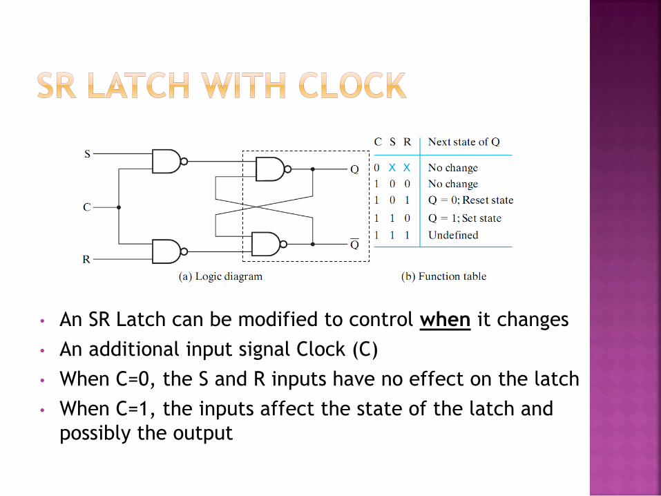
• An SR Latch can be modified to control when it changes
• An additional input signal Clock (C)
• When C=0, the S and R inputs have no effect on the latch
• When C=1, the inputs affect the state of the latch and
possibly the output
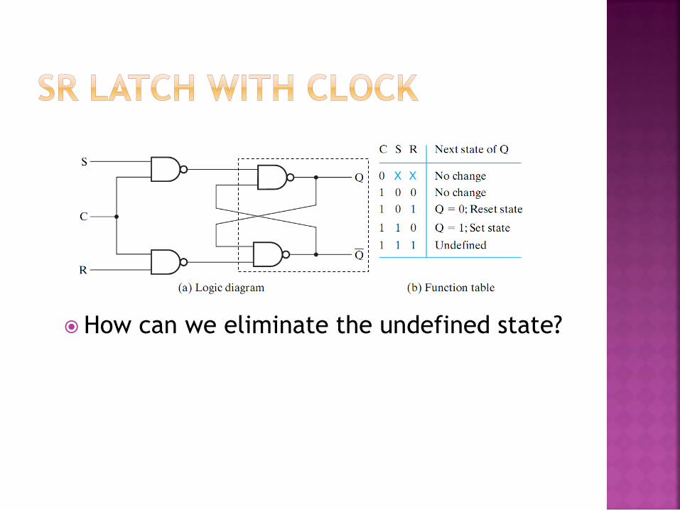
How can we eliminate the undefined state?
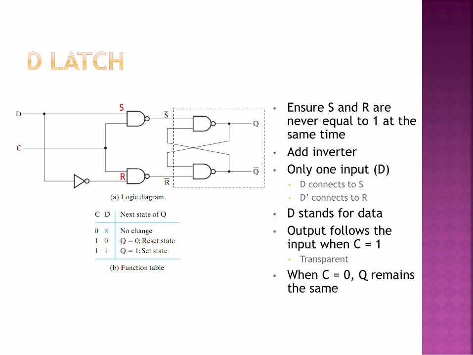
• Ensure S and R are never equal to 1 at the same time
• Add inverter
• Only one input (D) • D connects to S
• D’ connects to R
• D stands for data
• Output follows the input when C = 1 • Transparent
• When C = 0, Q remains the same
R
S

• A latch is designated by a rectangular block with inputs on the left and outputs on the right
• One output designates the normal output, the other (with the bubble) designates the complement
• For S’R’ (SR built with NANDs), bubbles added to the input
clk
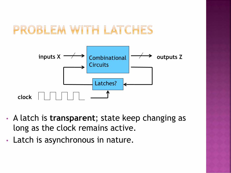
• A latch is transparent; state keep changing as
long as the clock remains active.
• Latch is asynchronous in nature.
Combinational
Circuits
inputs X outputs Z
Latches?
clock


• A flip-flop is a one bit memory similar to latches • Solves the issue of latch transparency • Latches are level sensitive memory element
• Active when the clock = 1 (whole duration)
• Flip-Flops are edge-triggered or edge-sensitive memory element • Active only at transitions; i.e. either from 0 1 or 1 0
positive (rising) edge negative (falling) edge
level

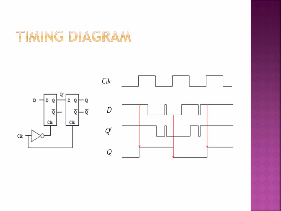
Construction of a D-Flip Flop with two D- Latches and
one inverter.
First Latch is called Master Latch and second is called
Slave Latch.
The output may change only once
A change in output is triggered by the positive edge of
clock
When the clock is ‘0’, the master D-latch is enabled
while slave D-latch would be disabled and vice versa
when clock is ‘1’. Hence positive edge triggered D-
Flip Flop

Master
D-Latch
Slave
D-Latch

• A Flip Flop is designated by a rectangular block with inputs on the left and outputs on the right (similar to latches)
• The clock is designated with an arrowhead
• A bubble designates a negative-edge triggered flip flops

SR-Flip Flop
Built using two SR latches
Master and Slave configuration
Q is sampled at the rising/falling edge only
Do it yourself
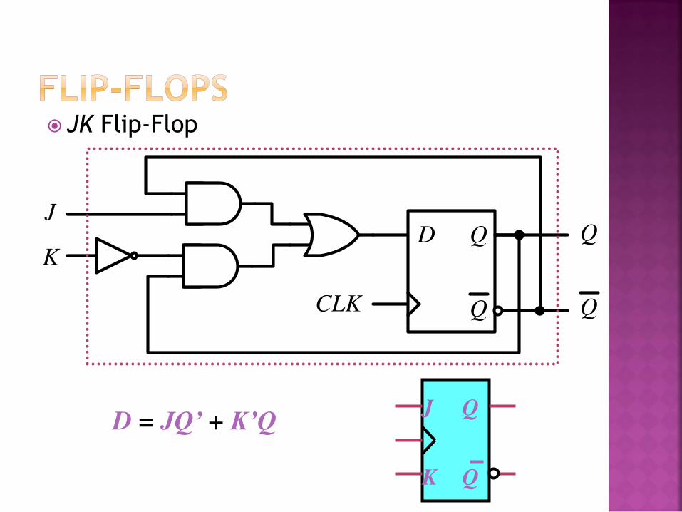
JK Flip-Flop
D Q
Q
Q
QCLK
J
K
J Q
Q K
D = JQ’ + K’Q

T Flip-Flop
D = TQ’ + T’Q = T Q
J Q
Q K
T D Q
Q
T
D = JQ’ + K’Q T Q
Q

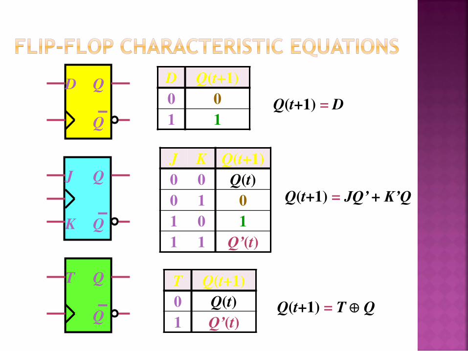
• A characteristic table defines the operation of a
flip flop in a tabular form
• Next state is defined in terms of the current
state and the inputs
• Q(t) refers to current state (before the clock arrives)
• Q(t+1) refers to next state (after the clock arrives)
• Similar to the truth table in combinational
circuits

• A characteristic equation defines the operation
of a flip flop in an algebraic form
• For D-FF
• Q(t+1) = D
• For JK-FF
• Q(t+1) = J Q’ + K’ Q
• For T-FF
• Q(t+1) = T Q

D Q
Q
D Q(t+1)
0 0
1 1
Reset
Set
J K Q(t+1)
0 0 Q(t)
0 1 0
1 0 1
1 1 Q’(t)
No change
Reset
Set
Toggle
J Q
Q K
T Q
Q
T Q(t+1)
0 Q(t)
1 Q’(t) No change
Toggle
D Q
Q
D Q(t+1)
0 0
1 1 Q(t+1) = D
J K Q(t+1)
0 0 Q(t)
0 1 0
1 0 1
1 1 Q’(t)
Q(t+1) = JQ’ + K’Q
J Q
Q K
T Q
Q
T Q(t+1)
0 Q(t)
1 Q’(t) Q(t+1) = T Q

Analysis / Derivation
J Q
Q K
J K Q(t) Q(t+1)
0 0 0 0
0 0 1 1
0 1 0
0 1 1
1 0 0
1 0 1
1 1 0
1 1 1
No change
Reset
Set
Toggle

Analysis / Derivation
J Q
Q K
J K Q(t) Q(t+1)
0 0 0 0
0 0 1 1
0 1 0 0
0 1 1 0
1 0 0
1 0 1
1 1 0
1 1 1
No change
Reset
Set
Toggle

Analysis / Derivation
J Q
Q K
J K Q(t) Q(t+1)
0 0 0 0
0 0 1 1
0 1 0 0
0 1 1 0
1 0 0 1
1 0 1 1
1 1 0
1 1 1
No change
Reset
Set
Toggle

Analysis / Derivation
J Q
Q K
J K Q(t) Q(t+1)
0 0 0 0
0 0 1 1
0 1 0 0
0 1 1 0
1 0 0 1
1 0 1 1
1 1 0 1
1 1 1 0
No change
Reset
Set
Toggle

Analysis / Derivation
J Q
Q K
J K Q(t) Q(t+1)
0 0 0 0
0 0 1 1
0 1 0 0
0 1 1 0
1 0 0 1
1 0 1 1
1 1 0 1
1 1 1 0
K
0 1 0 0
J 1 1 0 1
Q Q(t+1) = JQ’ + K’Q
Similarly, Characteristic equations for SR-Flip
Flop, D-Flip Flop and T-Flip Flop can be
derived using K-Map.

• In a sequential circuit, outputs depends on inputs and previous inputs • Previous inputs are stored as binary information into
memory
• The stored information at any time defines a state
• Similarly, next state depends on inputs and present state
• Two types of sequential circuits: Synchronous and Asynchronous
• Two types of Memory elements: Latches and Flip-Flops.
• Flip-flops are built with latches
• A flip-flop is described using characteristic table/equation