
5. USE ASSEMBLING DISASSEMBLING
21
5. U SE , ASSEMBLING, DISASSEMBLING OF BEARINGS Reliable running of rolling bearings depends not only on the quality of the bearing itself. There are also other factors affecting the service life of the rolling bearing, especially operating environment, technical mounting and correct maintenance. It is necessary to keep machines in a good operational condition. Besides securing necessary co- axial state it is important to protect bearings from an extreme temperature, moisture and pollution. It is necessary to choose the correct mounting process and select suitable tools to avoid of damaging bearings during the mounting already. The important precondition for the maximal service life of bearings is to keep the plans of oiling and maintenance, to control operational conditions. 5.1 TERMS OF RELIABLE BEARING OPERATION 5.1.1 Storage of Roller Bearings Dry and dust-free space with almost constant temperature creates the best conditions to store bearings. Bearings must be stored in original not damaged wrapping and taken out just prior to mounting. Big bearings must be put horizontally and supported all around in order not to deform the rings. Bearings are preserved at the producer´s for the storage period of 24 months. The storage conditions must fulfill these requirements: - The temperature in the store-room must be from 5°C to 35°C. The thermal amplitude must not exceed 5 °C. - Rolling bearings must not be put on the fresh wood shelf, near cold walls or on the stone floors. - Relative air moisture must not exceed 60%. There is a danger of corosion at higher relative moisture. - Bearings must not be put too near heating or water piping. - Bearings must not be exposed to the direct sunshine. - No chemicals may be stored at the same space with bearings (acids, ammoniacs, chloride of lime and etc.) since they cause bearings corosion. Each store-room must have hygrometer and thermometer. 5.1.2 Influence of Bearing Clearance on his Life and Operation Precision The size of a radial clearance of a radial bearing at constant operational conditions determines service life of a rolling bearing and reliability of operation of housing and also accuracy of running of a turning shaft, spindle. A very big radial clearance causes external weight that spreads at smaller number of rolling elements, and this way their weight increases and accuracy of shaft running worsen. The operational clearance of rolling bearings depends on its clearance size at not installed state, on overlap size of placement of an inner and outer ring and on thermal declivity between rings. The operational clearance cannot be measured at running, so the negative clearance may be generated, ergo pre-stress and, consequently, premature destruction of bearings may occur. Even though a bigger operational clearance might not ruin bearings quickly, it determines lowering of its load rating and durability. An axial clearance of a radial bearing is mostly not very important. Axial bearings should not work with clearance because adverse gliding of rolling elements can appear between raceways of rings, caused by centrifugal forces and bearing torques. At high perimeter speed of axial ball-bearings, balls can glide oblique rolling direction under the influence of bearing torque, so spiral traces of jam are generated. 5.1.3 Relation of Tolerance Class of Rolling Bearing to its Arrangement The dimensional accuracy of dimensions and accuracy of running of rolling bearings complies with the international standards. Most of machine and equipment arrangements suit standard tolerance class P0. Bearings with higher tolerance than P0 are used in the arrangements requiring higher accuracy of running, e.g. for placement of work- ing machines and instruments spindle, etc., and also when a bearing exceeds its limiting speed. The abutment components of the arrangement in higher tolerance class must be produced.
Transcript of 5. USE ASSEMBLING DISASSEMBLING

5. USE, ASSEMBLING, DISASSEMBLING OF BEARINGS
Reliable running of rolling bearings depends not only on the quality of the bearing itself. There are also other factors affecting the service life of the rolling bearing, especially operating environment, technical mounting and correct maintenance. It is necessary to keep machines in a good operational condition. Besides securing necessary co-axial state it is important to protect bearings from an extreme temperature, moisture and pollution. It is necessary to choose the correct mounting process and select suitable tools to avoid of damaging bearings during the mounting already.The important precondition for the maximal service life of bearings is to keep the plans of oiling and maintenance, to control operational conditions.
5.1 TERMS OF RELIABLE BEARING OPERATION
5.1.1 Storage of Roller BearingsDry and dust-free space with almost constant temperature creates the best conditions to store bearings. Bearings must be stored in original not damaged wrapping and taken out just prior to mounting. Big bearings must be put horizontally and supported all around in order not to deform the rings.
Bearings are preserved at the producer´s for the storage period of 24 months.The storage conditions must fulfi ll these requirements:- The temperature in the store-room must be from 5°C to 35°C. The thermal amplitude must not exceed 5 °C.- Rolling bearings must not be put on the fresh wood shelf, near cold walls or on the stone fl oors.- Relative air moisture must not exceed 60%. There is a danger of corosion at higher relative moisture.- Bearings must not be put too near heating or water piping.- Bearings must not be exposed to the direct sunshine.- No chemicals may be stored at the same space with bearings (acids, ammoniacs, chloride of lime and etc.) since they cause bearings corosion. Each store-room must have hygrometer and thermometer.
5.1.2 Infl uence of Bearing Clearance on his Life and Operation PrecisionThe size of a radial clearance of a radial bearing at constant operational conditions determines service life of a rolling bearing and reliability of operation of housing and also accuracy of running of a turning shaft, spindle. A very big radial clearance causes external weight that spreads at smaller number of rolling elements, and this way their weight increases and accuracy of shaft running worsen. The operational clearance of rolling bearings depends on its clearance size at not installed state, on overlap size of placement of an inner and outer ring and on thermal declivity between rings. The operational clearance cannot be measured at running, so the negative clearance may be generated, ergo pre-stress and, consequently, premature destruction of bearings may occur. Even though a bigger operational clearance might not ruin bearings quickly, it determines lowering of its load rating and durability. An axial clearance of a radial bearing is mostly not very important.Axial bearings should not work with clearance because adverse gliding of rolling elements can appear between raceways of rings, caused by centrifugal forces and bearing torques. At high perimeter speed of axial ball-bearings, balls can glide oblique rolling direction under the infl uence of bearing torque, so spiral traces of jam are generated.
5.1.3 Relation of Tolerance Class of Rolling Bearing to its ArrangementThe dimensional accuracy of dimensions and accuracy of running of rolling bearings complies with the international standards. Most of machine and equipment arrangements suit standard tolerance class P0. Bearings with higher tolerance than P0 are used in the arrangements requiring higher accuracy of running, e.g. for placement of work-ing machines and instruments spindle, etc., and also when a bearing exceeds its limiting speed. The abutment components of the arrangement in higher tolerance class must be produced.

It is also necessary to secure adequate toughness of the arrangement at variable loads, low temperature fl uctua-tion in bearings and possibility of the bearing clearance adjustment to reach higher accuracy of the arrangement running.
5.1.4 Rolling Bearings Arrangement DesignThe arrangment design must be developed not to allow additional loads when mounting and running; axial clamp-ing (overload) of bearings when mounting and shaft and housing dilatation when running. Therefore a bearing seating alignment and adequate thoughness and dimensions of abutment components must be considered when developing the design.The special attention to the arrangement design must be paid in relation to the oiling system and sealing of bear-ings space. It is necessary to ensure regular re-lubrication in bearings lubricated by grease. If the re-lubrication intervals are short it is necessary to build a slinger ring into the housing in order not to overfi ll the bearing space with grease and to overheat a bearing. The oil lubrication is used if the operation speed and temperatures don’t allow to use grease lubrication , and if the bearings are located in the space where oil is used for lubrication of other components, e.g. gear-wheels.The selection of the method of the oil lubrication (oil bath, circulating oil, oil drop, oil jet or oil mist) depends on operating conditions and lubricating system of the certain machine equipment.The construction design must ensure that bearings have adequate quantity of oil not only at normal running but mainly when starting-up the machine. Excessive oil increases oil temperature.For more details on lubrication see previous chapter.

5.2 MOUNTING OF ROLLING BEARINGS
5.2.1 Mounting of Rolling BearingsHousing bearings Mounting method Mounting equipment
Cylindrical Journal
small bearingcold cold mounting cases, hammer, mechanical or hydraulical presshot hot mounting inductive equipment, heating-up plate, heating-up box
medium bearing hot hot mounting inductive equipment, heating-up box, hot-air heater, heating-up tub,inductive heating-up equipment
large bearing hot large bearing hot mounting inductive equipment, heating-up box, hot-air heater,heating-up tub, inductive heating-up equipment
Tapered Journalsmall bearing cold small bearing cold mounting lock nut, hook spanner, press
medium bearing cold medium bearing cold mounting lock nut, hook spanner, hydraulic nut, pumplarge bearing hot large bearing hot mounting heating-up equipment, hydraulic equipment
Adapter and Withdrawal sleevessmall bearing cold small bearing cold mounting lock nut, hook spanner, hydraulic nut, pump
medium bearing cold medium bearing cold mounting lock nut, hook spanner, hydraulic nut, pumplarge bearing hot large bearing heat mounting heating-up equipment, hydraulic nut, pump
Small bearing: the bore diameter < 75 mmMedium bearing: thebore diameter 75 to 200 mmLarge bearing: the bore diameter > 200 mm
5.2.2 Mounting WorkplaceIt is necessary to protect bearings from dirt, foreign elements and shocks. Therefore it is necessary to choose dry and dust-free mounting workplace. No components can be produced and modifi ed in a mounting workplace (saw-ing, grinding, welding, etc.) nor pressed air can be used so the saw-dust, dust and other foreign elements do not penetrate into a bearing. When foreign elements such as dust, abradants, etc. penetrate into a bearing, together with the lubricant they create material damaging raceways, rolling elements and the cage. Accuracy of a bearing is lowered this way. Thicker dirt penetrating into a bearing will roll into raceways by rolling bodies and damage the raceways which will put the bearing out of service prematurely.
5.2.3 Bearing Preparation for MountingBefore starting the mounting it is necessary to check whether the designation on the packaging and the bearing designation complies with data on the drawing. It is important that not only the basic designation but also the supplementary designation which determines the bearing design comply with the data on the drawing. Bearings producers protect bearings from corosion by preservative material which is neutral to common plastic lubricants and oils and has good lubricating properties. Therefore bearings are not washed before mounting. If they are pre-served by slushing grease (bearings which are still stored at users premises), the grease is removed from the bore, bearing surface and the front of bearing rings only. If a grasepreserved bearing is lubricated by circulating oil when in operation, it needs to be washed out because of a danger that slushing grease blocks ducts or oil feed holes.Benzoline with 5 to 10% part of light mineral oil, benzole, naphtha, pure petroleum at common temperature. Inor-ganic cleansers can also be used to wash out bearings at the temperature of 70 to 80°C. Bearings made of light metals must not be washed out by inorganic cleansers. When washed out, bearing is immediately preserved by light oil.
5.2.4 Preparation of Arrangement Components for MountingBefore mounting all the components must be properly cleaned and cleared of burrs. Also lubricating holes and threads must be properly cleaned. Housing components areas must be produced within determined tolerance. The violation of bearing operation can be caused by exceeding permissible dimensional and shape deviations and not

keeping the supporting front surfaces for bearings rings in an upright position.Therefore it is necessary to check out properly determined dimensions of housing areas on the shaft and in the housing before mounting. If there are no special data on drawing, it generally stands that ovality and taper ratio must not exceed half of the tolerance zone. Then it is necessary to check out shoulder and chamfer of shaft bypass. Grooves and other defects must not be in front of the shoulder. The circularity, the angle of the taper and the surface straightness of the tapered surface must be checked out at the tapered housing areas. The taper ratio of the shaft must correspond with the tapered bore of the inner ring. For most of bearings types the taper ratio is 1:12, at some types it is 1:30. Figure 25 shows measuring of the shaft diameter, and the Figure 26 shows measuring of the bearing housing bore.
Figure 25
Figure 26
Figure 28Figure 27
5.2.5 Control of Housing AreasThe micrometer calipers adjusted by control gauge is used for measuring of the shafts. The inside calipers also adjusted by control gauge measures pillow blocks. The dial indicatior (see Figure 27) with 0,001 mm accuracy is used for evaluation.
The tapered gauge (see Figure 28) is the simplest gauge for small taper areas. The method of bluing shows wheth-er the taper ratio of the journal corresponds with the gauge and it is corrected until the gauge sits all over the width.

5.2.6. Cold Mounting
5.2.6.1 Cylindrical Seating SurfacesDifferent constructions and bearings sizes re-quire also different mounting procedures. The mounting force must always be applied on the fi rmly fi tted ring when mounting non-separable bearings (see Figure 29) e.g. single row ball bearings. If the force acts on the outer ring when mounting the inner ring, it is transfered to the rolling elements and raceways of rings and can damage them.
Mounting of separable bearings is simplier (seeFigure 30), both rings can be mounted sepa-rately. The inner ring with the journal will be inserted into the outer ring after pressing. To avoid grooves on functional bearing areas when inserting a ring into a bearing, the screw-shape turn should be done.
In standard fi tting, small bearings up to the di-ameter of approximately 75 mm can be cold pressed on the shaft. The shaft and bearing bore will be cleaned by a clean cloth and softly oiled up. Mechanical or hydraulic press is used when cold mounting (see Figure 31).
Figure 29
Figure 31
Figure 30

With no no press avaliable when fi tting the bearing with minor overlap, it can be knocked on the journal by light hits of a hammer on mounting sleeve. A bearing ring can be knocked directly by the hammer under no circumstances. Mounting sleeves of soft steel with fl at front area are suitable for mounting (see Figure 32). The diameter of this sleeve should be a little bigger than the diameter of the bearing bore. The outer diam-eter of the sleeve must not be bigger than the diameterof the front inner ring, whereas the cage damage could occur.
Balls overhang through the rings width in certain types of double row self-aligning ball bearings.The mounting attachement must have a recess for this reason (see Figure 34).
The seating areas can be damaged in press fi tted bearings made of light metal alloy. Therefore it is ap-propriate to heat up the bearing housing or to cool the bearings down. Mixture of dry ice and alcohol is used for cooling. The temperature of bearing rings must not drop under -50°C. Due to cage clearance the rollers might hit even the front area of the inner ring in bigger cylindrical bearings. Mounting sleeve facilitates mount-ing by guiding the rollers on raceway. (see Figure 35).
If the inner ring is solid fi tted and the outer ring is slide fi tted, the bearing is pressed onto the shaft fi rst and then inserted together with the shaft into the housing. If both rings are solid fi tted, they are mounted at the same time. The attachement is seated on both rings in this case (see Figure 33).
Figure 32
Figure 33
Figure 34
Figure 35

The proper clearance in milimeters is set up between rollers and fl ange on the inner ring according to the table 38 at mounting of the cylindrical roller bearing with one fl ange on the ring (type NJ).
Bearing size BoreDiameter rows Tab. 38
NJ2 NJ3 NJ404 20 0,55 0,55 0,605 25 0,55 0,55 0,806 30 0,6 0,6 0,907 35 0,75 0,75 0,9508 40 0,8 0,8 1,010 50 0,8 0,8 1,112 60 1,0 1,0 1,314 70 1,1 1,1 1,516 80 1,25 1,25 1,618 90 1,5 1,5 1,820 100 1,65 1,65 1,922 110 1,95 1,95 2,124 120 2,0 2,0 2,426 130 2,0 2,0 2,728 140 2,15 2,15 2,830 150 2,3 2,3 3,032 160 2,5 2,5 3,134 170 2,65 2,65 3,136 180 2,65 2,65 -
5.2.6.2 Tapered Seating Surfaces
Bearings with tapered bore are mounted either on the tapered shaft directly or on the cylindrical shaft using the adapter or withdrawal sleeve. Supporting areas of the shaft, sleeve and in the bearing bore can be softly oiled up before mounting. As the bearing is driven up the, the inner ring expands and the radial clearance is reduced. The reduction in radial internal clearance become the measure for the inner ring fi xing and is determined as the differ-ence between the radial clearance before and radial clearance after mounting of a bearing. The radial clearance is measured before mounting, it is constantly controlled when driving the bearing up the tapered seat until it reaches necessary reduction, and hence the correct fi xing on the shaft. Instead of the reduction in radial internal clearance an axial displacement of a bearing on the tapered seat can be measured.
Table 40 contains values of the reduction in radial clearance. The radial clearance is measured using the feeler gauge (see Figure 36). It is necessary to measure the radial clearance in both rows of spherical rollers of double row spherical roller bearings. The inner ring is not axially displaced only if the clearance in both rows of spherical rollers is the same. In cylindrical roller bearings the inner and the outer ring can be mounted separately. If the inner ring is separable, instead of measuring the reduction in radial internal clearance, the expansion of the inner ring can be measured using the stirrup micrometer. Hydraulic or mechanical equipment is used to press the bearing on the seating surface.
Small and medium sized bearings can be fi xed onto the tapered journal using an adjusting nut (see Figure 37). The hook spanner is used for tightening the nut.

Nominal diameter d (mm) Required radial
clearance reductionRequired shifting on the cone 1:12 Required shifting on the cone 1:30
over incl. on the shaft on the casing on the shaft on the casing
24 30 0,015-0,020 0,30-0,35 0,30-0,40 - -
30 40 0,020-0,025 0,35-0,40 0,35-0,45 - -
40 50 0,025-0,030 0,40-0,45 0,45-0,50 - -
50 65 0,030-0,035 0,45-0,60 0,50-0,70 - -
65 80 0,040-0,050 0,60-0,75 0,70-0,85 - -
80 100 0,045-0,060 0,70-0,90 0,75-1,00 1,70-2,20 1,80-2,40
100 120 0,050-0,070 0,70-1,10 0,80-1,20 1,90-2,70 2,00-2,80
120 140 0,065-0,090 1,10-1,40 1,20-1,50 2,70-3,50 2,80-3,60
140 160 0,075-0,100 1,20-1,60 1,30-1,70 3,00-4,00 3,10-4,20
160 180 0,080-0,110 1,30-1,70 1,40-1,90 3,20-4,20 3,30-4,60
180 200 0,090-0,130 1,40-2,00 1,50-2,20 3,50-4,50 3,60-5,00
200 225 0,100-0,140 1,60-2,20 1,70-2,40 4,00-5,50 4,20-5,70
225 250 0,110-0,150 1,70-2,40 1,80-2,60 4,20-6,20 4,60-6,20
250 280 0,120-0,170 1,90-2,60 2,00-2,90 4,70-6,70 4,80-6,90
280 315 0,130-0,190 2,00-3,22 2,20-3,20 5,00-7,50 5,20-7,70
315 355 0,150-0,210 2,40-3,40 2,60-3,60 6,00-8,20 6,20-8,40
355 400 0,160-0,215 2,60-3,60 2,90-3,90 6,50-9,00 6,80-9,20
400 450 0,170-0,230 3,10-4,10 3,40-4,40 7,70-10,0 7,00-10,4
450 500 0,200-0,260 3,30-4,40 3,60-4,80 8,20-11,0 8,40-11,2
500 560 0,210-0,280 3,70-5,00 4,10-5,40 9,20-12,5 9,60-12,8
560 630 0,240-0,320 4,00-5,40 4,40-5,90 10,0-13,5 10,4-14,0
630 710 0,260-0,350 4,60-6,20 5,10-6,80 11,5-15,5 12,0-16,0
710 800 0,340-0,450 5,30-7,00 5,80-7,60 13,3-17,5 13,6-18,0
800 900 0,370-0,500 5,70-7,80 6,30-8,40 14,3-19,5 14,8-20,0
900 1000 0,410-0,550 6,30-8,50 7,00-9,40 15,8-21,0 16,4-22,0
1000 1120 0,450-0,600 6,80-9,00 7,60-10,2 17,0-23,0 18,8-24,0
1120 1250 0,490-0,650 7,40-9,80 8,30-11,0 18,5-25,0 19,6-26,0
1250 1400 0,550-0,720 8,30-10,8 9,30-12,1 21,0-27,0 22,2-28,3
Tab. 39

Bearings with adapter sleeve (see Figure 38) are pressed on the tapered seating area using the adjusting nut. The sleeve, nut and washer checked before mounting. The radial clearance is measured and preserving agent is removed from the bearing bore and surface. When mounting, the adapter sleeve is positioned onto the journal fi rst then the bearing is inserted followed by locking washer and nut. The bearing is inserted on the tapered seating by tightening the nut until its radial clearance is reduced to specifi ed value. Pressing force is considerably high when pressing large bearings. Therefore it is recommended to spread mixture of oil and colloid graphite on the nut thread and nut front area. Adpater sleeves are mostly used for smooth shafts, therefore when mounting it is advisable to secure bearing position using the clamping pad (see Figure 39) which is removed after mounting.All mounting areas are fi rst cleaned when mounting the bearing onto the withdrawal sleeve. The bearing is put on the shaft and the withdrawal sleeve is being inserted (see Figure 40) into the gap between the shaft and bearing bore, so that the necessary reduction in radial internal clearance is reached.Bigger force is necessary for pressing the sleeve of bigger bearings. The withdrawal nut with thrust bolts (see Figure 41) makes mounting easier in such cases.
Figure 36
Figure 40
Figure 38
Figure 37
Figure 41
Figure 39
5.2.7.2 Heating up on Heating Plate and in Heating BoxBearings with the bore smaller than 100 mm are heated up using electric heating plates equipped with the tempera-ture control. Spiral heaters with the temperature control with accuracy of ±2°C are suitable for heating up larger bearings with the bore from 100 to 300 mm. Electric heating boxes with the built-in regulative thermostat and protec-tive equipment against bearings overheating are suitable for heating higher quantity of small and medium bearings.
5.2.7.3 Hot-air Heater Heating upThe hot-air heater bearings heating up is a reliable and clean method. The temperature is regulated by the thermo-stat. This method also protects bearings from impurities. The disadvantage is that heating up takes relatively long time, therefore relatively big heaters must be available during serial mounting.
5.2.7.4 Inductive Heating upThe equipment for inductive heating up is suitable for fast, reliable and clean hot mounting, even when mounting smaller quantity of bearings. The inductive mounting equipment provides possibility to heat up inner rings of cylin-drical roller bearings and needle roller bearings with the bore diameter from 100 mm. This equipment is economical to use when serial mounting of higher quantity of cylindrical roller bearings inner rings, for example at axle bearings of track vehicles or at metallurgical plants and rolling-mills equipment.
5.2.7 Heat Mounting
A force necessary for pressing the ring is increased quadratically with linear increase of bearing dimensions at constant surface pressure. Therefore it is advisable to heat mount larger bearings or mount them using pressurized oil. Heat mounting is suitable for bearings with cylindrical bore pressurized oil is better for bearings with tapered bore. Both methods can be used for both bore shapes. Heating up the bearing to 70 or 80°C makes the expansion of the rings suitable for easy mounting. Higher temperatures (over 100°C) lower bearing hardness and its durability and can also change its dimensions (except for bearings stabilised for high temperature operation). Bearings with shields (-2Z, -2 ZR) and sealing (-2 RS, -2RSR) can be heated up to maximum temperature of 80°C, however, never in oil bath.
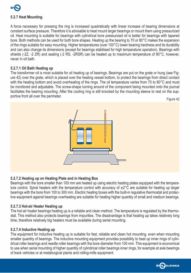
5.2.7.1 Oil Bath Heating upThe transformer oil is most suitable for oil heating up of bearings. Bearings are put on the grate or hung (see Fig-ure 42) over the grate, which is placed over the heating vessel bottom, to protect the bearings from direct contact with the heating bottom and avoid overheating of the rings. The oil temperature varies from 70 to 80°C and must be monitored and adjustable. The screw-shape turning around of the component being mounted onto the journal facilitates the bearing mounting. After the cooling ring is still knocked by the mounting sleeve to rest on the sup-portive front all over the perimeter.
Figure 42

5.2.8 Mounting of Bearings Using Pressurized Oil
The oil under the pressure approximately 12,5 to 75 MPa is led between the contact areas when mounting using pressurized oil method. The oil fi lm divides the inner bearing ring and journal so that they can move on each other with minimal force without risk of damaging the surface. The pure mineral oil should be used when mounting using pressurized oil. In majority of cases the light mineral oil with viscosity from 45 to 68 mm2.s-1 at 40°C is suitable. It is better to use less viscous oil which reliably es-capes from the contact housing areas after mounting. There are shaft grooves, feed channels and also connecting threads of oil injector or the oil pump therminal for pressing the oil in between the ring and journal contact areas (see Figure 43).
Pressurized oil cases with grooves are used for large bearings fi xed onto the shaft using adapter or withdrawal sleeves. The adapter sleeves have grooves on the surface and in the bore. The withdrawal sleeves (see Figure 44) have grooves on the surface and oil feed on the side of the thread or on the side of the tapered seat.The oil injector with the capacity 10 to 25 cm3, depending on its size, is suitable for distribution of the pressurized oil in small and medium sized bearings and can reach the pressure pres-sure up to 250. When necessary to distribute bigger oil quantity in medium and large sized bearings, the oil pump is more suit-able.
5.2.8.1 Mounting of Bearings with Tapered Bore
The drive fi t of the bearing inner ring with tapered bore can be reached by pressing it onto the shaft while the inner ring is fl exibly expanded, causing reduction of the bearings radial clearance. Reducing the size of the original radial clearance represents the measure for the adequate drive fi t on the ta-pered seat. The difference between the radial clearance before and after mounting represents the radial clearance reduction. Therefore the actual radial clearance must be determined by measuring before mounting. After pressing the bearing on the tapered seat, the clearance is being measured until it reaches necessary reduction and hence the required drive fi t.
Fixing nuts, lifting screws or hydraulic nuts are used for press-ing (see Figure 45 – 47). Depending on the size hydraulic with-drawal and adapter sleeves have connecting threads for the pressurized oil feed. The high-pressure hose pump is attached to the sleeve by screwing, reduction and a steel pipe. The oil is forced in between the contact areas when mounting. The axial mounting force is reached by 6 or 8 lifting screws in the nut which is mounted onto the shaft (the Figure 48) or on the adapter sleeve (see Figure 49).
Figure 43
Figure 46
Figure 45
Figure 44
B
(0,3 – 0,4) B

Figure 47The mounting pad prevents damaging of the withdrawal sleeve or the bearing by lifting screws. The oil feed goes through the nut mounted onto the shaft after pressing the withdrawal sleeve in. The axial displacement of the bearing or withdrawal sleeve is determined according to the required radial clearance reduction. When measuring radial clearance, bearing must be relieved from the oil pressure.
When mounting with pressurized oil, it is neccesary to leave the bearing depending on its size under the preload of a nut and screws for 15 to 30 minutes after reaching specifi ed radial clearance reduction and pressure release in order to let the oil run out of the tapered surfaces.
5.2.9 Mounting of Double Row Cylindrical Roller Bearings with Tapered Bore
Mounting of NN30K and NNU49K bearings requires a special process. Measuring the raceway or circle encasing the rollers with a special gauge determines the size of the radial clearance or preload.
The gauge is chosen considering the brearing design and the separability of the rings. In cylindrical roller bearings The diam-eter difference of the outer ring raceway and circle encasing the rollers represents the specifi ed radial clearance or preload. Figure 50 shows the gauge principle for measuring NN30K bearings.
The diameter of the raceway on the mounted outer ring is measured with the gauge when mounting. This diameter is transferred to the gauge for measuring the circle encasing the rollers and the gauge is applied on the inner ring with rollers. The inner ring is driven up on its tapered seat until the microca-tor shows the value of the specifi ed clearance or preload.
Figure 50
Figure 48
Figure 49
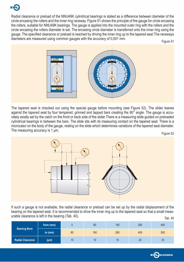
Bearing Borefrom (mm) 0 80 180 280 400
to (mm) 80 180 280 400 500
Radial Clearance (μm) 10 10 15 20 25
Radial clearance or preload of the NNU49K cylindrical bearings is stated as a difference between diameter of the circle encasing the rollers and the inner ring raceway. Figure 51 shows the principle of the gauge for circle encasing the rollers, suitable for NNU49K bearings. The gauge is applied into the mounted outer ring with the rollers and the circle encasing the rollers diameter is set. The encasing circle diameter is transferred onto the inner ring using the gauge. The specifi ed clearance or preload is reached by driving the inner ring up to the tapered seat.The raceways diameters are measured using common gauges with the accuracy of 0,001 mm.
The tapered seat is checked out using the special gauge before mounting (see Figure 52). The slider leanes against the tapered seat by four tempered, grinned and lapped bars creating the 90° angle. The gauge is accu-rately axially set by the catch on the front or back side of the slider.There is a measuring slide guided on preloaded cylindrical bearings in between the bars. The slide sits with its measuring contact on the tapered seat. There is a microcator on the body of the gauge, resting on the slide which determines variations of the tapered seat diameter. The measuring accuracy is 1 μm.
If such a gauge is not avaliable, the radial clearance or preload can be set up by the radial displacement of the bearing on the tapered seat. It is recommended to drive the inner ring up to the tapered seat so that a small meas-urable clearance is left in the bearing (Tab. 40).
Figure 51
Figure 52
Tab. 40

It is recommended to check the arrangement temperature when mounting preloaded bearings. It is advisable to choose the way of mounting in each individual case depending on the arrangement design, size and type of the bearing.The accuracy of bearing clearance or preload set up controlled by monitoring bearings temperature when test run-ning of high-turn spindles. Test running lasts until the bearings tempertaure is stabilised. Testing period is from ½ to 3 hours depending on the machine size. The constatnt temperature from 50 to 60°C is acceptable as a guiding temperature value for accurately set clearance or preload.
This measured axial clearance determines the size of the axial displacement on the Figure 53 diagram.
Figure 53
B
dsd
B2
0 5
axia
l mov
emen
t (m
m)
10 15 20 25 30
ds
d
35 0 5 10 15 20 25 30 35
0,7
0,6
0,5
0,4
0,3
0,2
0,1 axia
l mov
emen
t (m
m)
0,7
0,6
0,5
0,4
0,3
0,2
0,1
NNU49K NNU30K
lowering radial clearance (μm) lowering radial clearance (μm)
ds
d
0,00,40,60,70,8
0,00,40,60,7
0,8

5.2.10 Mounting of Thrust Bearings
The thrust bearings shaft washers have usually a slide fi t and the housing washers are always fi t with a clearance. In double direction thrust bearings the shaft washer must be axially clamped (see Figure 54 and 55).
The preload set up is the same as in tapered roller bearings. The high-revolution thrust bearings must be constantly preloaded to ensure correct rolling elements rolling. The preload is reached using a nut (Figure 54) or calibrated washer (see Figure 55), eventually using springs.
5.2.11 Mounting of Single Row Ball Bearings with Ball Surface and Wider Inner Ring (Insert Ball Bearings)
It needs to be checked before mounting whether the shaft is manufactured within required tolerance. In case that housing units are not delivered as a bearing unit, i.e. without mounted bearings, bearings need to be mounted into housing units. When mounting, the position of re-lubricating hole with re-lubricating groove must be maintained. This way the whole unit is ready for mounting onto the shaft. Bearings are secured on the shaft only after fi xing the housing unit to the supportive area.
Figure 54
Figure 55

Bearing mounting Dismounting method Dismounting equipmentCylindrical journal
Small bearing mechanical pullers
Medium bearing mechanicalhydraulicthermal
pullershydraulic equipmentinduction equipment
heating ring
Large bearing hydraulicthermal
hydraulic equipmentinduction equipment
heating ringTapered journal
Small bearing mechanicalhydraulic
pullershydraulic equipment
Medium bearing hydraulic hydraulic equipment Large bearing hydraulic hydraulic equipment Adapter sleeve
Small bearing mechanicalhydraulic
bar, hammerhydraulic equipment
Medium bearing mechanicalhydraulic
bar, hammer, mechanical presshydraulic equipment
Large bearing hydraulic hydraulic equipment Withdrawal sleeve
Small bearing mechanicalhydraulic
withdrawal sleevehydraulic equipment
Medium bearing mechanicalhydraulic
withdrawal sleevehydraulic equipment
Large bearing hydraulic hydraulic equipment
Small bearing: bore diameter < 75 mm
Medium bearing: bore diameter 75 to 200 mm
Large bearing: bore diameter > 200 mm
5.3 DISMOUNTING OF ROLLING BEARINGS
5.3.1 Dismounting Method Selection
5.3.2 Mechanical Methods
5.3.2.1 Dismounting of Bearings with Cylindrical Bore
To keep the possibility for bearings and housing units connecting components to be used again, they must be dismounted using proper equipment in a dry and dust-free workplace in order not to be damaged. The dismountingfi xture should seat only on the ring which is being dismounted. A force necessary for dismounting must not be car-ried through the rolling elements. Otherwise the bearing operating surfaces could be damaged. In non-separable bearings the slide fi tted ring is dismounted fi rst (see Figure 56).
Usually a bigger force is necessary for tightening the drive fi tted bearing ring then for pressing it as a result of driveseated mounting surfaces. In separable bearings the rings can be dismounted separately (see Figure 57).

Mechanic pullers’ (see Figure 58) or hydraulic presses’ withdrawal force acting on drive fi tted ring directly or via the supporting part e.g. labyrinth ring is mostly used to dismount small bearings.
Dismounting of bearings is facilitated if the equipment design suggests a threaded hole for dismounting lifting screws or groves for puller which can be attached to the bearing ring directly (see Figure 60, 61).
If the front of the inner ring fully seats on the rib of the shaft without grooves for puller then the single row ball bear-ings, tapered bearings and cylindrical bearings can be dismounted using a special collet pullers. Using this puller also bearings which are still not built in the housing unit can be removed from the journal.
Figure 56
Figure 58
Figure 60
Figure 57
Figure 59
Figure 61

5.3.2.2 Dismounting of Bearings with Tapered BoreWhen dismounting bearings seated directly on the tapered journal or on the adapter sleeve, the nut must be par-tially loosened fi rst. The inner ring is relieved from the tapered supporting areas of the journal or adapter sleeve with light hits of a hammer. For relieving the inner ring a soft metal bar is used (see Figure 62). If a press is used when dismounting, the fi xture is rested on the nut (see Figure 63) or directly on the adapter sleeve. Bearings fi xed to the journal by the adapter sleeve are dismounted by the withdrawal nut (see Figure 64). A nut with lifting screws is used in more complicated and larger bearings dismounting (see Figure 65). A washer is put in between the lift-ing screws and the front of the inner ring. Dismounting of withdrawal sleeves by hydraulic nut is more simple (see Figure 66). Withdrawal sleeves overhanging the shaft end are supported in the hole by the thick-walled ring.
Figure 62
Figure 64
Figure 63
Figure 65
Figure 66

5.3.3 Dismounting of Bearings Using Thermal Methods
5.3.3.1 Heating RingThe heating ring (see Figure 67) is suitable for dismounting of the inner rings of the cylindrical roller bearings. The ring is made of aluminium alloy and has a radial notches. Handling the ring is enabled by thermally isolated holders. The ring has the same width as the bearing and its bore has the same diameter as the bearing inner ring raceway.The ring is heated up to 200 or 300°C on the electric heating board and it is inserted on the pulled inner ring coated with the thick oxide-proof oil, and then it is clamped by holders. The heat is transferred from the heating ring into the inner bearing ring fairly quickly. When the overhanging in the housing of the shaft is relieved the ring is removed together with the heating ring. The heating ring is suitable for dismounting of medium sized bearing rings. For each bearing size a corresponding heating ring must be applied.
5.3.3.2 Inductive Dismounting EquipmentThe inductive dismounting equipment is predominantly used for dismounting the inner rings from the cylindrical roller and needle roller bearings with the bore diameter from 100 mm which are drive fi tted on the shaft. Heating up takes place so quickly that only a little heat penetrates into the shaft, while the rings are easily released. The rings are heated to temperature of 80 to 100°C.
5.3.3.3 Circular BurnerIn case there are no ribs and ducts for hydraulic mounting on the shaft, the inner rings of larger separable bearings can be heated up by fl ame. The circular burner proved to be suitable in such cases. Distance between the pipes and ring surface should be 40 to 50 mm. In common gas pressure the burner holes have the diameter 2 mm, they are alternately distanced with the spacing of 18 to 24 mm. When heating up the burner must be aligned with bear-ing ring and it is slowly and evenly moving in the axial direction over the bearing ring surface.
5.3.4 Dismounting of Bearing Using Hydraulic MethodThe oil is pressed in between the contact areas when using the hydraulic method. The oil fi lm breaks contact be-tween components which can be moved together by relatively small force and without the danger of surface damag-ing. The hydraulic method is equally suitable for dismounting of joints with tapered contact areas as well as joints with cylindrical contact areas. In both cases the journal must be grooved with feed channels and connecting threads (see Figure 68) for the pressurized oil to be attached. Larger withdrawal and adapter sleeves are produced with grooves and channels for pressurized oil. The approximately 45 mm2.s-1 viscosity oil at 40°C can be used for dismounting. The approximately 300 mm2.s-1 viscosity transmission oil at 40°C is used when the contact areas are damaged.
Figure 67 Figure 68

The sealed ring forcing oil in between the contact areas is pushed against the front side of the pressed bearing. The oil is forced in between the contact areas until the end of dismounting process by attaching the special sleeve to the journal front. If it is not possible for this sleeve to be used an approximately mm2.s-1 viscosity oil at 40°C must be used. This oil creates a fi lm in between the contact areas which keeps up 4 to 7 minutes. This time is suffi cient for the bearing dismounting. The withdrawal sleeves are relatively expensive and are used only when a higher quantity of bearings need to be dismounted (e.g. axle bearings dismounting. The induction heating is more suitable for dismounting of bearing mainly at regular maintenance.
5.3.4.2 Dismounting of Bearings with Tapered BoreWhen dismounting bearings seated directly on the tapered journal or on the withdrawal or adapter sleeve, it is suf-fi cient to press the oil in between the contact areas. It is essential to pay an increased attention as the contact is released at once. Considering the risk of injury, the axial bouncing of bearing or sleeve when dismounting must be limited by the nut on the shaft (see Figure 70) or by the nut on the sleeve (see Figure 71), eventually backstopped (see Figure 72).A complicated removal of the adapter sleeve can be facilitated with a withdrawal nut mounted on the sleeve. If such a nut is equipped with lifting screws (see Figure 73), a washer is inserted underneath these screws to protect the rib of a bearing ring from direct pressure impact.If the bearing rests on supporting ring the adapter sleeve can be relieved by hydraulic nut. The hydraulic nut must rest on the ending plate (see Figure 74).
5.3.4.1 Dismounting of Bearings with Cylindrical BoreThe hydraulic method is usually used only when dismounting bearings with cylindrical bore. The removal fi xture is used when dismounting (see Figure 69).
Oil is forced into both oil channels by two pumps after inserting the fi xture. After the oil penetrates in between the roller areas and rings are relieved, the ring is removed using the fi xture so that it equally covers front groove on both sides. The oil feed is interrupted in this position. A spring is inserted into the leading withdrawal sleeve fi xture and it is preloaded. The spring compression must be bigger than the length by which the ring is seated on the shaft. The spring preload should be approximately P = 20.d (N). The inner ring is removed by the spring’s force after oil is pressed into the front channel. If there are no oil grooves or feed channels in the journal, the oil can be pressed in between the contact areas from the front of the inner ring.
Figure 69

Figure 70
Figure 72
Figure 71
Figure 73
Figure 74