· PDF fileShift mechanism, checking Selector lever cable, checking and adjusting Ignition...
307
WWW.ALL-TRANS.BY
Transcript of · PDF fileShift mechanism, checking Selector lever cable, checking and adjusting Ignition...
WWW.ALL-TR
ANS.BY

WWW.ALL-TR
ANS.BY
4 Spd. Automatic Transmission 096
00 - General, Technical data
Transmission identification
Code letters, model/engine applications, ratios, equipment
Capacities
Repair instructions
01 - On Board Diagnostic (OBD)
On Board Diagnostic (OBD), general information Technical data On Board Diagnostic (OBD) program - Guide Electronic component locations
On Board Diagnostic (OBD) program VAG 1551 Scan Tool (ST), connecting and selecting functions List of selectable functions Diagnostic Trouble Code (DTC) Memory, checking Diagnostic Trouble Code (DTC) table Diagnostic Trouble Code (DTC) Memory, erasing Basic setting, initiating Reading measured value block
Transmission electrical testing Electrical testing on Transmission Control Module (TCM) with 38-pin connector Test table Electrical testing on Transmission Control Module (TCM) with 68-pin connector Test table
32 - Torque converter
Torque converter Torque converter, identifying Torque converter, draining Torque converter oil seal, removing and installing
37 - Automatic Transmission - Controls, Housing
Shift mechanism, servicing
WWW.ALL-TR
ANS.BY
Shift mechanism, checking Selector lever cable, checking and adjusting Ignition lock, checking Shift mechanism, disassembling and assembling Selector lever, disassembling and assembling Locking cable, removing and installing Locking cable, adjusting
Transmission, checking Shift points, checking Stall speed, checking Main pressure, checking
Transmission, removing and installing
ATF level ATF level, checking ATF, topping up
Gear selector elements
Transmission, disassembling and assembling ATF cooler and ATF filler tube, removing and installing Planetary gearbox disassembly and assembly, overview I - ATF pump to support tube, removing and installing II - Reverse gear clutch -K2- to large sun gear, removing and installing III - Free wheel and reverse gear brake -B1-, removing and installing IV - Planet carrier and input gear, removing and installing Planetary gearbox, disassembling and assembling Planetary gearbox adjustments, overview Planet carrier, adjusting Reverse gear brake -B1-, adjusting Clutch play between -K1- and -K2-, adjusting 2nd and 4th gear brake -B2-, adjusting
38 - Automatic Transmission - Gears, Hydraulic controls
ATF pump, disassembling and assembling
Free wheel with -B1- piston, disassembling and assembling
1st to 3rd gear clutch -K1- with turbine shaft, disassembling and assembling
Reverse gear clutch -K2-, disassembling and assembling
WWW.ALL-TR
ANS.BY
4th gear clutch -K3- with pump shaft, disassembling and assembling
Valve body, removing and installing Valve body conductor strip with transmission fluid temperature sensor, removing and installing
Parking lock, disassembling and assembling
39 - Final drive, Differential
Oil in final drive, checking
Drive flange oil seal, removing and installing
Final drive, disassembling and assembling Repair overview Input gear, removing and installing Drive pinion, removing and installing Differential, removing and installing Differential, disassembling and assembling
Final drive, adjusting Adjustment overview Adjustments to be completed after replacing individual components Drive pinion, adjusting Input gear, adjusting Differential, adjusting
WWW.ALL-TR
ANS.BY
00-1
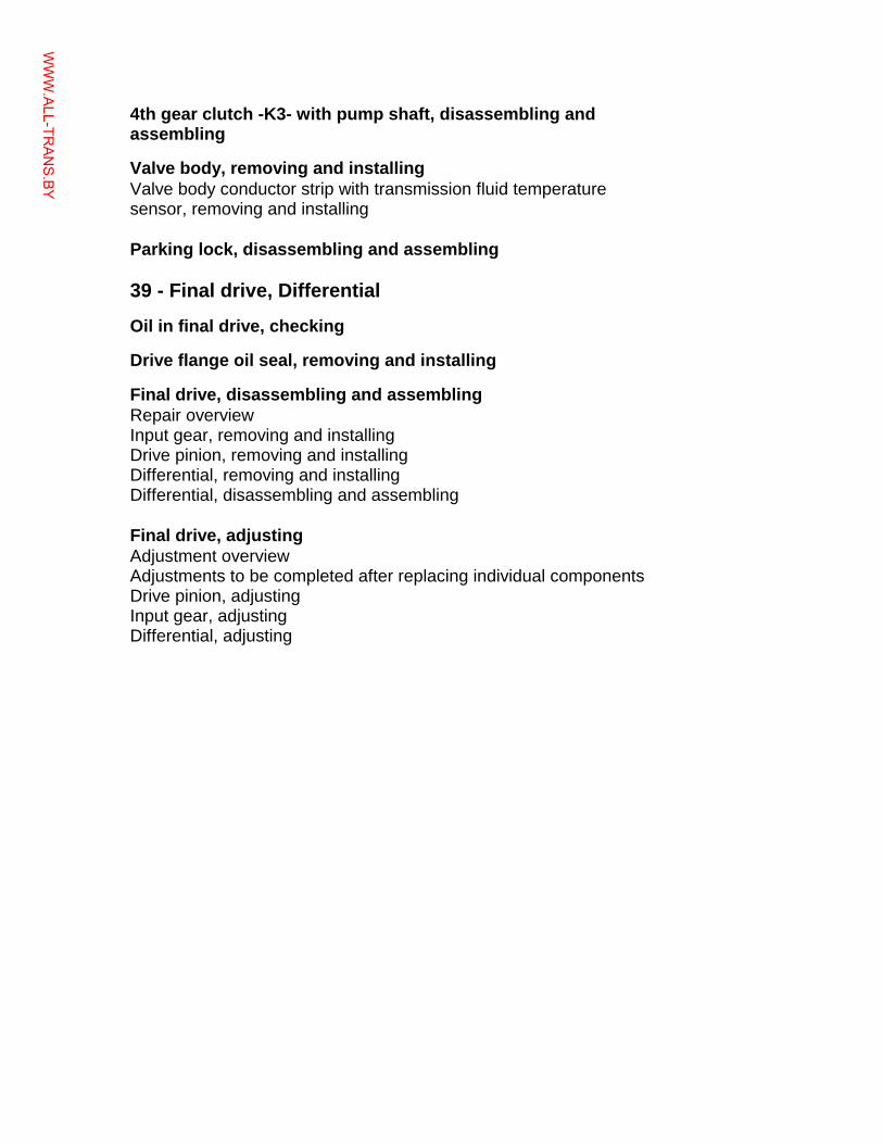
Transmission identification The 4-speed automatic transmission 096 is
installed in the Passat beginning in the 1995 model year.
It may be installed in combination with either a 4-cylinder or a 6-cylinder engine. Applications page 00-3 .
The transmission is identified by type (096), code letters and date of manufacture.
Location on transmission
Code letters (arrow -1-)
Automatic transmission 096 (-arrow 2-)
Automatic transmission 096 (-2-)
Page 1 of 2Transmission identification
12/6/2004http://ebahn.bentleypublishers.com/vw/servlet/Display?action=Goto&type=repair&id=VW.B4.AT02.00.1
WWW.ALL-TR
ANS.BY
00-2
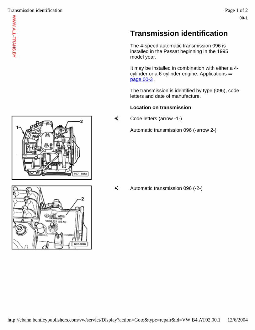
Transmission code letters and date of manufacture (arrow -1-)
The code letters of the transmission are also listed on the vehicle data plates.
Example: CFF 03 01 4
I I I I
I I I I
Transmission code letters
Day Month Year
Date (e.g. 3 Jan.,1994)
Page 2 of 2Transmission identification
12/6/2004http://ebahn.bentleypublishers.com/vw/servlet/Display?action=Goto&type=repair&id=VW.B4.AT02.00.1
WWW.ALL-TR
ANS.BY
00-3
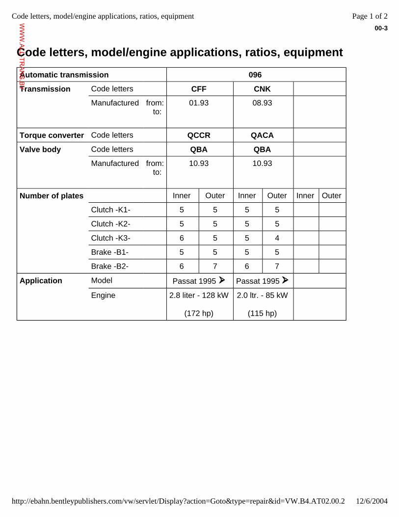
Code letters, model/engine applications, ratios, equipment
Automatic transmission 096
Transmission Code letters CFF CNK
Manufactured from: to:
01.93
08.93
Torque converter Code letters QCCR QACA
Valve body Code letters QBA QBA
Manufactured from: to:
10.93
10.93
Number of plates Inner Outer Inner Outer Inner Outer
Clutch -K1- 5 5 5 5
Clutch -K2- 5 5 5 5
Clutch -K3- 6 5 5 4
Brake -B1- 5 5 5 5
Brake -B2- 6 7 6 7
Application Model Passat 1995 Passat 1995
Engine 2.8 liter - 128 kW
(172 hp)
2.0 ltr. - 85 kW
(115 hp)
Page 1 of 2Code letters, model/engine applications, ratios, equipment
12/6/2004http://ebahn.bentleypublishers.com/vw/servlet/Display?action=Goto&type=repair&id=VW.B4.AT02.00.2
WWW.ALL-TR
ANS.BY
00-4
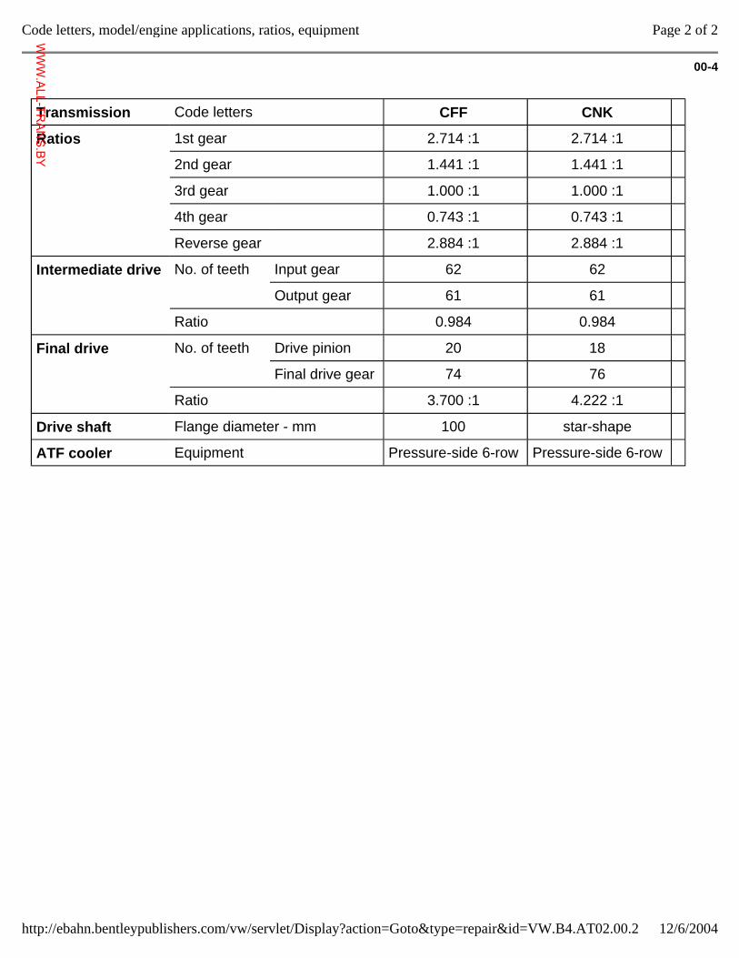
Transmission Code letters CFF CNK
Ratios 1st gear 2.714 :1 2.714 :1
2nd gear 1.441 :1 1.441 :1
3rd gear 1.000 :1 1.000 :1
4th gear 0.743 :1 0.743 :1
Reverse gear 2.884 :1 2.884 :1
Intermediate drive No. of teeth Input gear 62 62
Output gear 61 61
Ratio 0.984 0.984
Final drive No. of teeth Drive pinion 20 18
Final drive gear 74 76
Ratio 3.700 :1 4.222 :1
Drive shaft Flange diameter - mm 100 star-shape
ATF cooler Equipment Pressure-side 6-row Pressure-side 6-row
Page 2 of 2Code letters, model/engine applications, ratios, equipment
12/6/2004http://ebahn.bentleypublishers.com/vw/servlet/Display?action=Goto&type=repair&id=VW.B4.AT02.00.2
WWW.ALL-TR
ANS.BY
00-5
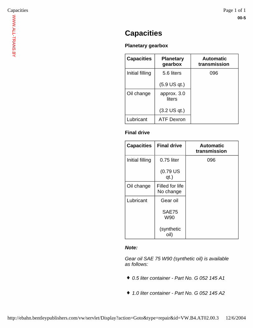
Capacities Planetary gearbox
Capacities Planetary gearbox
Automatic transmission
Initial filling 5.6 liters
(5.9 US qt.)
096
Oil change approx. 3.0 liters
(3.2 US qt.)
Lubricant ATF Dexron
Final drive
Capacities Final drive Automatic transmission
Initial filling 0.75 liter
(0.79 US qt.)
096
Oil change Filled for life No change
Lubricant Gear oil
SAE75 W90
(synthetic oil)
Note:
Gear oil SAE 75 W90 (synthetic oil) is available as follows:
0.5 liter container - Part No. G 052 145 A1
1.0 liter container - Part No. G 052 145 A2
Page 1 of 1Capacities
12/6/2004http://ebahn.bentleypublishers.com/vw/servlet/Display?action=Goto&type=repair&id=VW.B4.AT02.00.3
WWW.ALL-TR
ANS.BY
00-6
Repair instructions The maximum possible care and cleanliness and
proper tools are essential to ensure satisfactory and successful transmission repairs. The usual basic safety precautions also naturally apply when carrying out vehicle repairs.
A number of generally applicable instructions for individual repair operations, which are otherwise mentioned at various points in the Repair Manual, are summarized here. They apply to this Repair Manual.
Transmission
When an automatic transmission is replaced, the ATF in the planetary transmission ( page 37-43 ) and the gear oil in the final drive ( page 39-1 ) is to be checked and topped up as necessary. ATF and oil capacities and specifications page 00-5 .
When installing the transmission, make sure that the dowel sleeves for engine/transmission alignment are installed correctly.
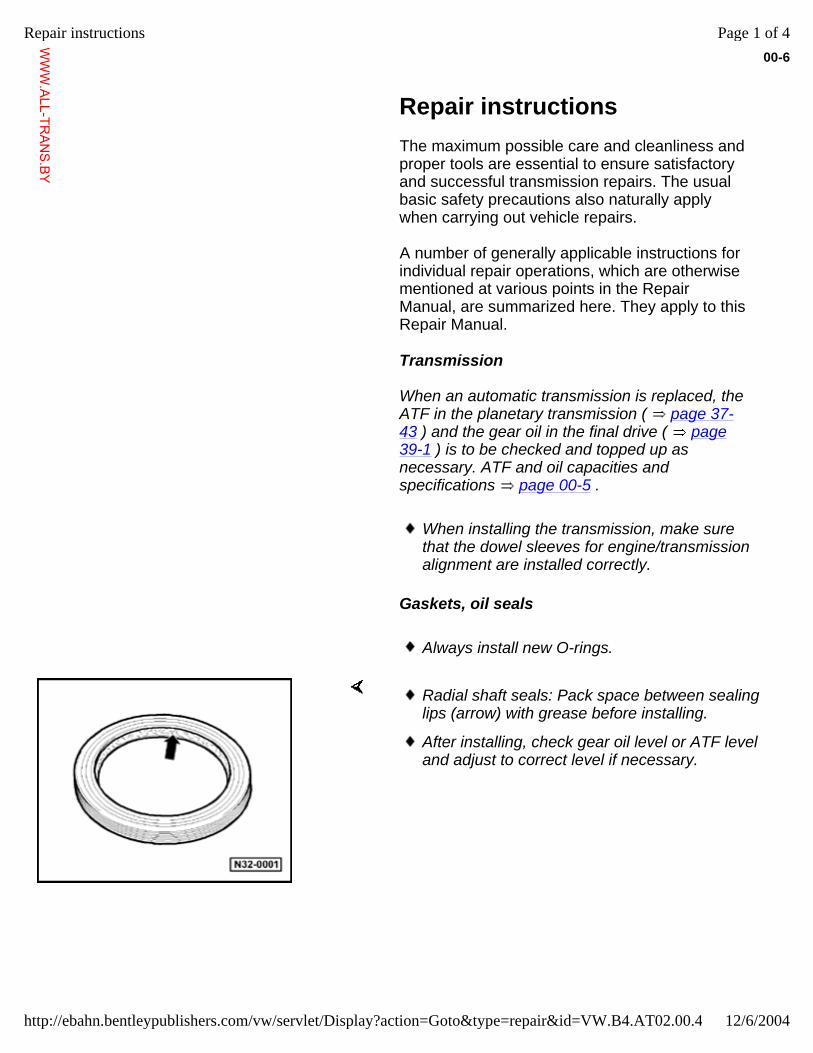
Gaskets, oil seals
Always install new O-rings.
Radial shaft seals: Pack space between sealing lips (arrow) with grease before installing.
After installing, check gear oil level or ATF level and adjust to correct level if necessary.
Page 1 of 4Repair instructions
12/6/2004http://ebahn.bentleypublishers.com/vw/servlet/Display?action=Goto&type=repair&id=VW.B4.AT02.00.4
WWW.ALL-TR
ANS.BY
00-7
Locking elements
Do not overstretch circlips; replace if necessary.
Circlips must be properly seated in the grooves.
Nuts, bolts
Nuts and bolts for attaching covers and housings must be loosened and tightened evenly, in an alternating pattern.
Do not distort particularly sensitive parts, e.g. valve body, and loosen or tighten diagonally in stages.
Tightening torques listed apply to unoiled nuts and bolts.
Threads of bolts that are secured by locking fluid are to be cleaned with a wire brush. Then insert bolts with AMV 185 100 A1.
Always replace self-locking nuts.
Bearings
Install needle bearings with the inscribed side (thicker sheet metal) facing the drift.
Lubricate all bearings in transmission with gear oil before installing. Oil with special care for measuring friction torque.
Heat the inner races of tapered roller bearings to approx. 100 C (212 F) before installing.
Do not interchange the inner or outer races between bearings of the same size.
Page 2 of 4Repair instructions
12/6/2004http://ebahn.bentleypublishers.com/vw/servlet/Display?action=Goto&type=repair&id=VW.B4.AT02.00.4
WWW.ALL-TR
ANS.BY
When tapered roller bearings are mounted on a shaft, always replace them together and use bearings from the same manufacturer.
Page 3 of 4Repair instructions
12/6/2004http://ebahn.bentleypublishers.com/vw/servlet/Display?action=Goto&type=repair&id=VW.B4.AT02.00.4
WWW.ALL-TR
ANS.BY
00-8
Shims
Measure shims at several points with a micrometer. Different tolerances in shims of the same nominal size make it possible to obtain the exact shim thickness required.
Check for signs of burrs and damage. Only install shims that are in perfect condition.
Inner plates
Place new inner plates in ATF fluid for 15 minutes before installing.
Valve body
Replace the valve body if any of the selector elements is scorched.
Clutches
Clutches K1, K2 and K3 should initially be dismantled only for cleaning. If parts are malfunctioning, replace clutch.
Clutch applications are determined by the transmission code letters.
On Board Diagnostic (OBD) program
Before carrying out any automatic transmission repairs, first determine the cause of the malfunction as precisely as possible with the aid of the On Board Diagnostic capability of the Transmission Control Module Repair Group 01.
Page 4 of 4Repair instructions
12/6/2004http://ebahn.bentleypublishers.com/vw/servlet/Display?action=Goto&type=repair&id=VW.B4.AT02.00.4
WWW.ALL-TR
ANS.BY
01-1
On Board Diagnostic (OBD), general information
Function
The 096 automatic transmission is controlled electro-hydraulically. "On Board Diagnostic" capability refers specifically to the electrical and electronic controls.
The Transmission Control Module (TCM) -J217- receives input signals from components that effect gear selection, and sends output signals to solenoid valves that control gear selection in the valve body.
The TCM -J217- is equipped with Diagnostic Trouble Code (DTC) Memory so that, in the event of an electrical/electronic component malfunction or an open circuit, the cause of the malfunction can be determined quickly.
Malfunctions in the monitored sensors or components are stored in DTC Memory along with an indication of the type of malfunction
Malfunctions that occur only occasionally are defined as "sporadic" malfunctions and are coded as such.
The Transmission Control Module (TCM) -J217- analyzes the information and distinguishes different types of malfunctions. Those that do not reoccur within 5 to 20 km (3 to 12 miles) or 6 to 24 minutes are stored as sporadic malfunctions.
Page 1 of 19On Board Diagnostic (OBD), general information
12/6/2004http://ebahn.bentleypublishers.com/vw/servlet/Display?action=Goto&type=repair&id=VW.B4.AT02.01.1
WWW.ALL-TR
ANS.BY
01-2
Electrical malfunctions that affect vehicle performance can be identified using the VAG 1551 Scan Tool (ST). The On Board Diagnostic (OBD) capabilities can only be fully exploited using operating mode 1 ("Rapid data transfer").
Functions of the VAG 1551 Scan Tool (ST) List of selectable functions, page 01-24 .
Safety functions of the Transmission Control Module (TCM)
If critical malfunctions occur while driving, the transmission will continue to operate in an emergency running mode. If a malfunction occurs while the selector lever is in position "D," "3" or "2," the 3rd gear emergency running mode is activated.
If a malfunction occurs while the selector lever is in position "1," "P," "N" or "R" the emergency running mode for that stage is activated.
If the engine is started again in the emergency running mode and the malfunction occurs when the selector lever is in position "D", "3" or "2" then 3rd gear is activated hydraulically, until the malfunction is repaired.
If there are malfunctions that result in emergency running, the transmission remains in the emergency running mode until the ignition is switched off.
Page 2 of 19On Board Diagnostic (OBD), general information
12/6/2004http://ebahn.bentleypublishers.com/vw/servlet/Display?action=Goto&type=repair&id=VW.B4.AT02.01.1
WWW.ALL-TR
ANS.BY
01-3
Malfunctions that may activate emergency running mode:
Open circuit in wiring, short-circuit, malfunctions in electrical or hydraulic components.
Transmission Control Module (TCM) recognition of malfunctions
If a malfunction exists for a certain time, it is stored as a static malfunction. A malfunction that is recognized but does not occur again within a certain time or distance is stored as a "sporadic malfunction."
Malfunctions that are stored in DTC Memory as sporadic malfunctions will be displayed as such when retrieved by the VAG 1551 Scan Tool (ST). In such cases, the letters "SP" appear on the right side of the Scan Tool display. If the printer is switched on, "sporadic DTC" is printed out after the malfunction is addressed.
Malfunctions that are stored in DTC Memory as sporadic malfunctions are automatically erased after 1,000 km (600 miles) or 20 hours.
Page 3 of 19On Board Diagnostic (OBD), general information
12/6/2004http://ebahn.bentleypublishers.com/vw/servlet/Display?action=Goto&type=repair&id=VW.B4.AT02.01.1
WWW.ALL-TR
ANS.BY
01-4
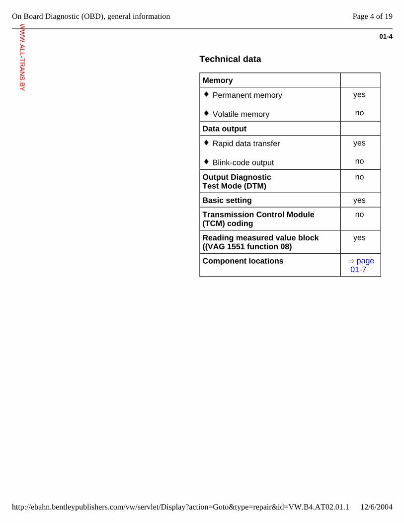
Technical data
Memory
Permanent memory
Volatile memory
yes
no
Data output
Rapid data transfer
Blink-code output
yes
no
Output Diagnostic Test Mode (DTM)
no
Basic setting yes
Transmission Control Module (TCM) coding
no
Reading measured value block ((VAG 1551 function 08)
yes
Component locations page 01-7
Page 4 of 19On Board Diagnostic (OBD), general information
12/6/2004http://ebahn.bentleypublishers.com/vw/servlet/Display?action=Goto&type=repair&id=VW.B4.AT02.01.1
WWW.ALL-TR
ANS.BY
01-5
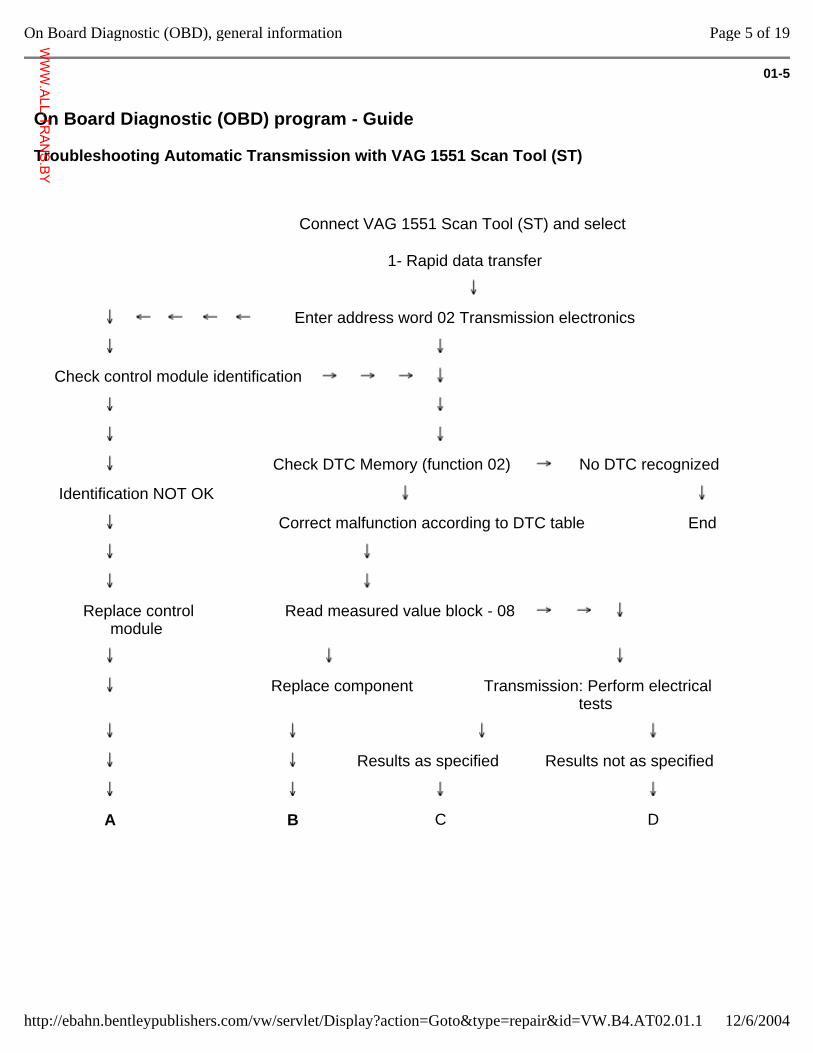
On Board Diagnostic (OBD) program - Guide
Troubleshooting Automatic Transmission with VAG 1551 Scan Tool (ST)
Connect VAG 1551 Scan Tool (ST) and select
1- Rapid data transfer
Enter address word 02 Transmission electronics
Check control module identification
Check DTC Memory (function 02) No DTC recognized
Identification NOT OK
Correct malfunction according to DTC table End
Replace control module
Read measured value block - 08
Replace component Transmission: Perform electrical tests
Results as specified Results not as specified
A B C D
Page 5 of 19On Board Diagnostic (OBD), general information
12/6/2004http://ebahn.bentleypublishers.com/vw/servlet/Display?action=Goto&type=repair&id=VW.B4.AT02.01.1
WWW.ALL-TR
ANS.BY
01-6
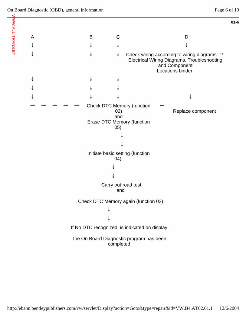
A B C D
Check wiring according to wiring diagrams Electrical Wiring Diagrams, Troubleshooting
and Component Locations binder
Check DTC Memory (function 02) and
Erase DTC Memory (function 05)
Replace component
Initiate basic setting (function 04)
Carry out road test and
Check DTC Memory again (function 02)
If No DTC recognized! is indicated on display
the On Board Diagnostic program has been completed
Page 6 of 19On Board Diagnostic (OBD), general information
12/6/2004http://ebahn.bentleypublishers.com/vw/servlet/Display?action=Goto&type=repair&id=VW.B4.AT02.01.1
WWW.ALL-TR
ANS.BY
01-7
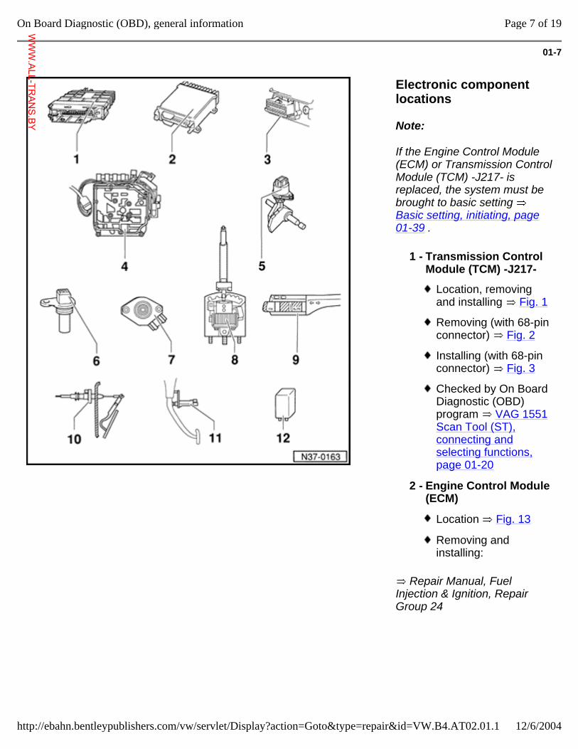
Electronic component locations
Note:
If the Engine Control Module (ECM) or Transmission Control Module (TCM) -J217- is replaced, the system must be brought to basic setting Basic setting, initiating, page 01-39 .
Repair Manual, Fuel Injection & Ignition, Repair Group 24
1 - Transmission Control Module (TCM) -J217-
Location, removing and installing Fig. 1
Removing (with 68-pin connector) Fig. 2
Installing (with 68-pin connector) Fig. 3
Checked by On Board Diagnostic (OBD) program VAG 1551 Scan Tool (ST), connecting and selecting functions, page 01-20
2 - Engine Control Module (ECM)
Location Fig. 13
Removing and installing:
Page 7 of 19On Board Diagnostic (OBD), general information
12/6/2004http://ebahn.bentleypublishers.com/vw/servlet/Display?action=Goto&type=repair&id=VW.B4.AT02.01.1
WWW.ALL-TR
ANS.BY
01-8
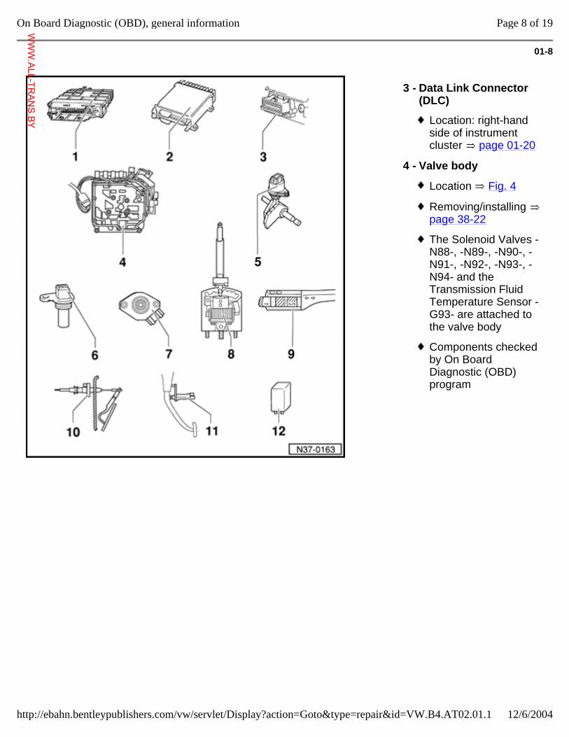
3 - Data Link Connector (DLC)
Location: right-hand side of instrument cluster page 01-20
4 - Valve body
Location Fig. 4
Removing/installing page 38-22
The Solenoid Valves -N88-, -N89-, -N90-, -N91-, -N92-, -N93-, -N94- and the Transmission Fluid Temperature Sensor -G93- are attached to the valve body
Components checked by On Board Diagnostic (OBD) program
Page 8 of 19On Board Diagnostic (OBD), general information
12/6/2004http://ebahn.bentleypublishers.com/vw/servlet/Display?action=Goto&type=repair&id=VW.B4.AT02.01.1
WWW.ALL-TR
ANS.BY
01-9
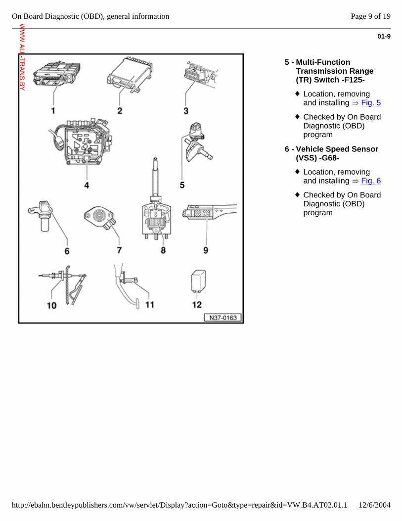
5 - Multi-Function Transmission Range (TR) Switch -F125-
Location, removing and installing Fig. 5
Checked by On Board Diagnostic (OBD) program
6 - Vehicle Speed Sensor (VSS) -G68-
Location, removing and installing Fig. 6
Checked by On Board Diagnostic (OBD) program
Page 9 of 19On Board Diagnostic (OBD), general information
12/6/2004http://ebahn.bentleypublishers.com/vw/servlet/Display?action=Goto&type=repair&id=VW.B4.AT02.01.1
WWW.ALL-TR
ANS.BY
01-10
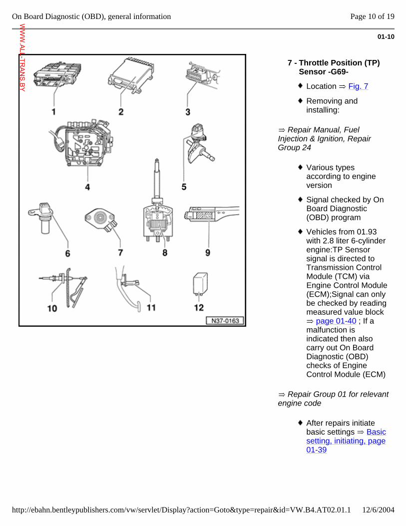
Repair Manual, Fuel Injection & Ignition, Repair Group 24
Repair Group 01 for relevant engine code
7 - Throttle Position (TP) Sensor -G69-
Location Fig. 7
Removing and installing:
Various types according to engine version
Signal checked by On Board Diagnostic (OBD) program
Vehicles from 01.93 with 2.8 liter 6-cylinder engine:TP Sensor signal is directed to Transmission Control Module (TCM) via Engine Control Module (ECM);Signal can only be checked by reading measured value block
page 01-40 ; If a malfunction is indicated then also carry out On Board Diagnostic (OBD) checks of Engine Control Module (ECM)
After repairs initiate basic settings Basic setting, initiating, page 01-39
Page 10 of 19On Board Diagnostic (OBD), general information
12/6/2004http://ebahn.bentleypublishers.com/vw/servlet/Display?action=Goto&type=repair&id=VW.B4.AT02.01.1
WWW.ALL-TR
ANS.BY
01-11
Repair Manual, Electrical Equipment, Repair Group 94
Repair Manual, General, Engine, Repair Group 20
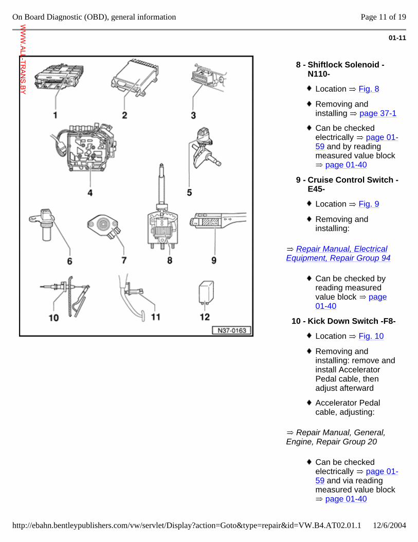
8 - Shiftlock Solenoid -N110-
Location Fig. 8
Removing and installing page 37-1
Can be checked electrically page 01-59 and by reading measured value block
page 01-40
9 - Cruise Control Switch -E45-
Location Fig. 9
Removing and installing:
Can be checked by reading measured value block page 01-40
10 - Kick Down Switch -F8-
Location Fig. 10
Removing and installing: remove and install Accelerator Pedal cable, then adjust afterward
Accelerator Pedal cable, adjusting:
Can be checked electrically page 01-59 and via reading measured value block
page 01-40
Page 11 of 19On Board Diagnostic (OBD), general information
12/6/2004http://ebahn.bentleypublishers.com/vw/servlet/Display?action=Goto&type=repair&id=VW.B4.AT02.01.1
WWW.ALL-TR
ANS.BY
01-12
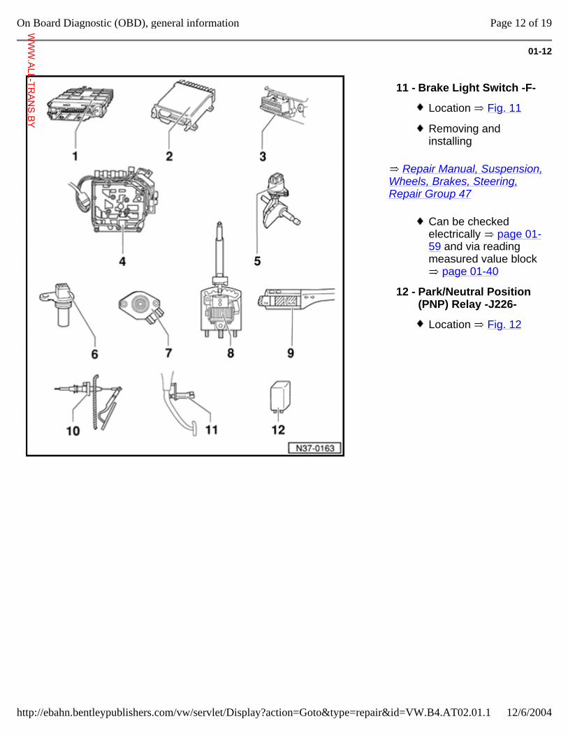
Repair Manual, Suspension, Wheels, Brakes, Steering, Repair Group 47
11 - Brake Light Switch -F-
Location Fig. 11
Removing and installing
Can be checked electrically page 01-59 and via reading measured value block
page 01-40
12 - Park/Neutral Position (PNP) Relay -J226-
Location Fig. 12
Page 12 of 19On Board Diagnostic (OBD), general information
12/6/2004http://ebahn.bentleypublishers.com/vw/servlet/Display?action=Goto&type=repair&id=VW.B4.AT02.01.1
WWW.ALL-TR
ANS.BY
01-13
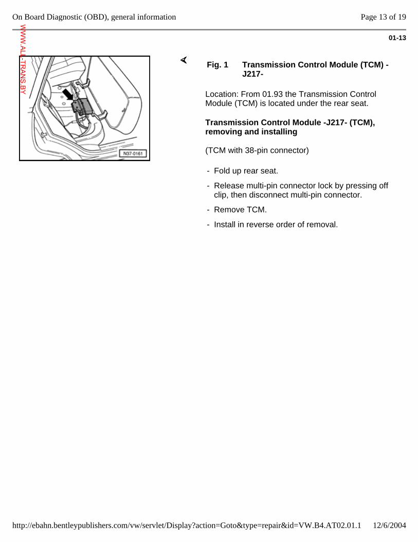
Location: From 01.93 the Transmission Control Module (TCM) is located under the rear seat.
Transmission Control Module -J217- (TCM), removing and installing
(TCM with 38-pin connector)
Fig. 1 Transmission Control Module (TCM) -J217-
- Fold up rear seat.
- Release multi-pin connector lock by pressing off clip, then disconnect multi-pin connector.
- Remove TCM.
- Install in reverse order of removal.
Page 13 of 19On Board Diagnostic (OBD), general information
12/6/2004http://ebahn.bentleypublishers.com/vw/servlet/Display?action=Goto&type=repair&id=VW.B4.AT02.01.1
WWW.ALL-TR
ANS.BY
01-14
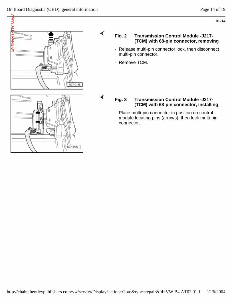
Fig. 2 Transmission Control Module -J217- (TCM) with 68-pin connector, removing
- Release multi-pin connector lock, then disconnect multi-pin connector.
- Remove TCM.
Fig. 3 Transmission Control Module -J217- (TCM) with 68-pin connector, installing
- Place multi-pin connector in position on control module locating pins (arrows), then lock multi-pin connector.
Page 14 of 19On Board Diagnostic (OBD), general information
12/6/2004http://ebahn.bentleypublishers.com/vw/servlet/Display?action=Goto&type=repair&id=VW.B4.AT02.01.1
WWW.ALL-TR
ANS.BY
01-15
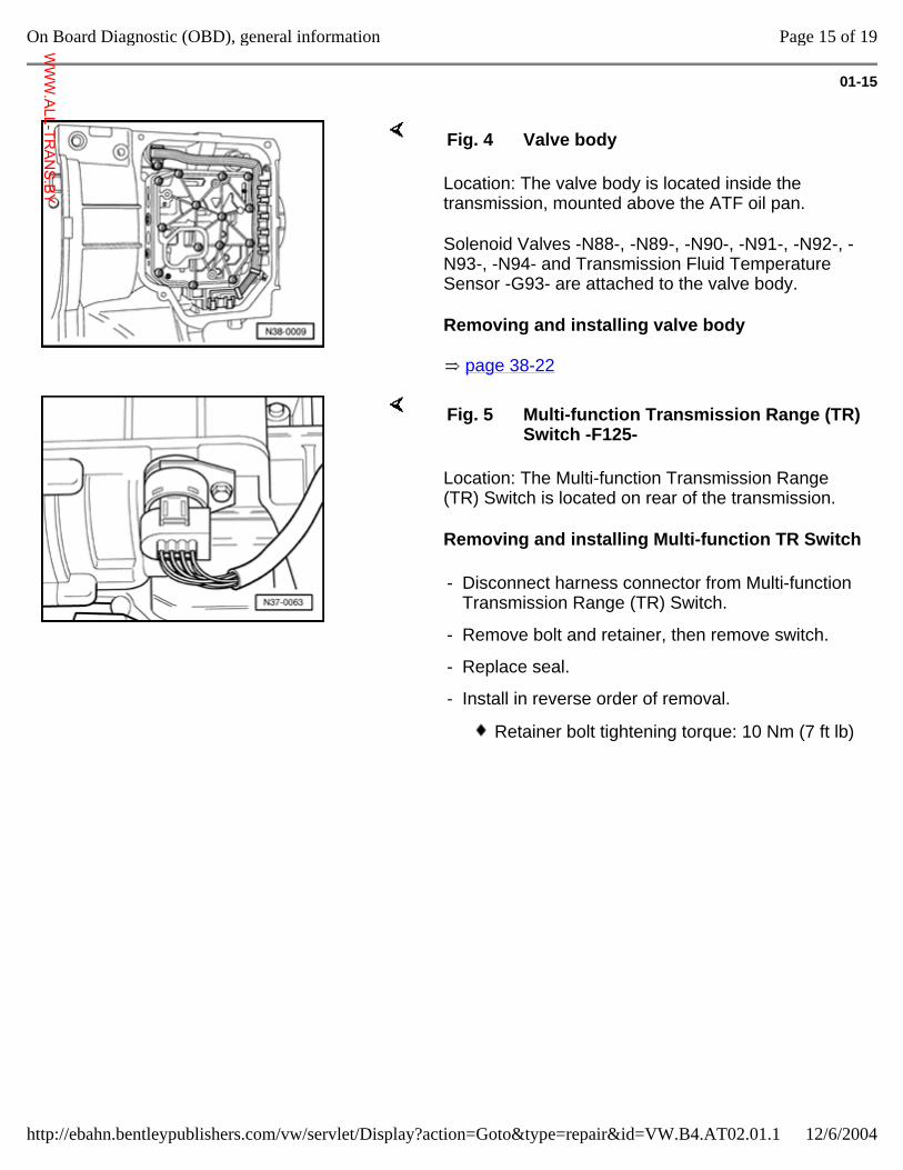
Location: The valve body is located inside the transmission, mounted above the ATF oil pan.
Solenoid Valves -N88-, -N89-, -N90-, -N91-, -N92-, -N93-, -N94- and Transmission Fluid Temperature Sensor -G93- are attached to the valve body.
Removing and installing valve body
page 38-22
Fig. 4 Valve body
Location: The Multi-function Transmission Range (TR) Switch is located on rear of the transmission.
Removing and installing Multi-function TR Switch
Fig. 5 Multi-function Transmission Range (TR) Switch -F125-
- Disconnect harness connector from Multi-function Transmission Range (TR) Switch.
- Remove bolt and retainer, then remove switch.
- Replace seal.
- Install in reverse order of removal.
Retainer bolt tightening torque: 10 Nm (7 ft lb)
Page 15 of 19On Board Diagnostic (OBD), general information
12/6/2004http://ebahn.bentleypublishers.com/vw/servlet/Display?action=Goto&type=repair&id=VW.B4.AT02.01.1
WWW.ALL-TR
ANS.BY
01-16
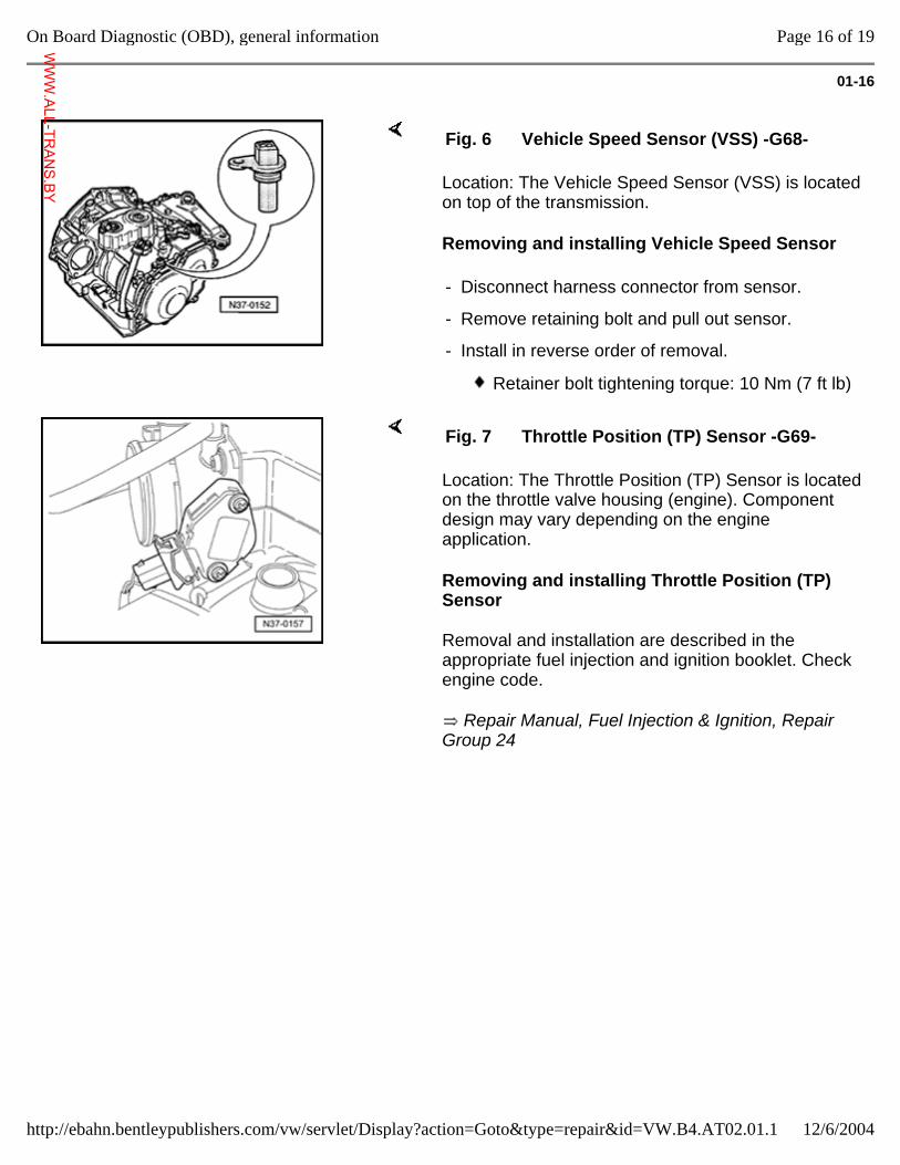
Location: The Vehicle Speed Sensor (VSS) is located on top of the transmission.
Removing and installing Vehicle Speed Sensor
Fig. 6 Vehicle Speed Sensor (VSS) -G68-
- Disconnect harness connector from sensor.
- Remove retaining bolt and pull out sensor.
- Install in reverse order of removal.
Retainer bolt tightening torque: 10 Nm (7 ft lb)
Location: The Throttle Position (TP) Sensor is located on the throttle valve housing (engine). Component design may vary depending on the engine application.
Removing and installing Throttle Position (TP) Sensor
Removal and installation are described in the appropriate fuel injection and ignition booklet. Check engine code.
Repair Manual, Fuel Injection & Ignition, Repair Group 24
Fig. 7 Throttle Position (TP) Sensor -G69-
Page 16 of 19On Board Diagnostic (OBD), general information
12/6/2004http://ebahn.bentleypublishers.com/vw/servlet/Display?action=Goto&type=repair&id=VW.B4.AT02.01.1
WWW.ALL-TR
ANS.BY
01-17
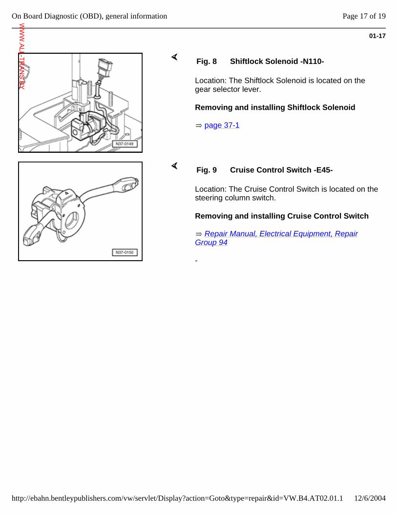
Location: The Shiftlock Solenoid is located on the gear selector lever.
Removing and installing Shiftlock Solenoid
page 37-1
Fig. 8 Shiftlock Solenoid -N110-
Location: The Cruise Control Switch is located on the steering column switch.
Removing and installing Cruise Control Switch
Repair Manual, Electrical Equipment, Repair Group 94
-
Fig. 9 Cruise Control Switch -E45-
Page 17 of 19On Board Diagnostic (OBD), general information
12/6/2004http://ebahn.bentleypublishers.com/vw/servlet/Display?action=Goto&type=repair&id=VW.B4.AT02.01.1
WWW.ALL-TR
ANS.BY
01-18
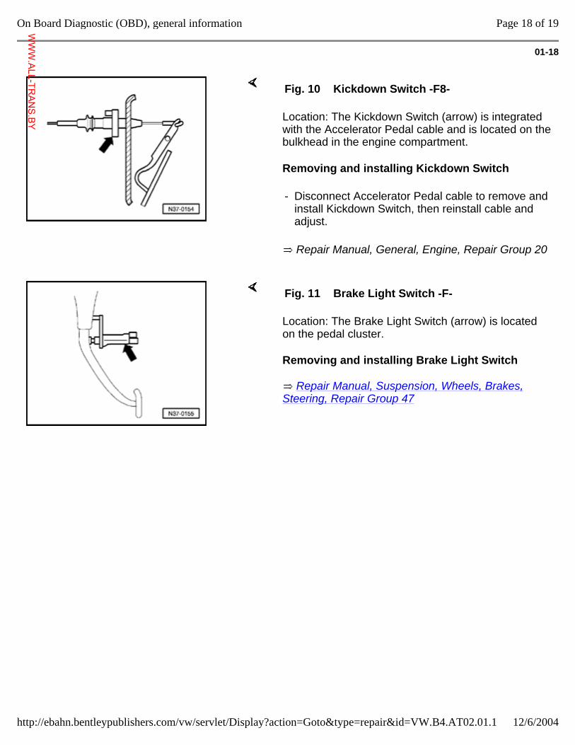
Location: The Kickdown Switch (arrow) is integrated with the Accelerator Pedal cable and is located on the bulkhead in the engine compartment.
Removing and installing Kickdown Switch
Repair Manual, General, Engine, Repair Group 20
Fig. 10 Kickdown Switch -F8-
- Disconnect Accelerator Pedal cable to remove and install Kickdown Switch, then reinstall cable and adjust.
Location: The Brake Light Switch (arrow) is located on the pedal cluster.
Removing and installing Brake Light Switch
Repair Manual, Suspension, Wheels, Brakes, Steering, Repair Group 47
Fig. 11 Brake Light Switch -F-
Page 18 of 19On Board Diagnostic (OBD), general information
12/6/2004http://ebahn.bentleypublishers.com/vw/servlet/Display?action=Goto&type=repair&id=VW.B4.AT02.01.1
WWW.ALL-TR
ANS.BY
01-19
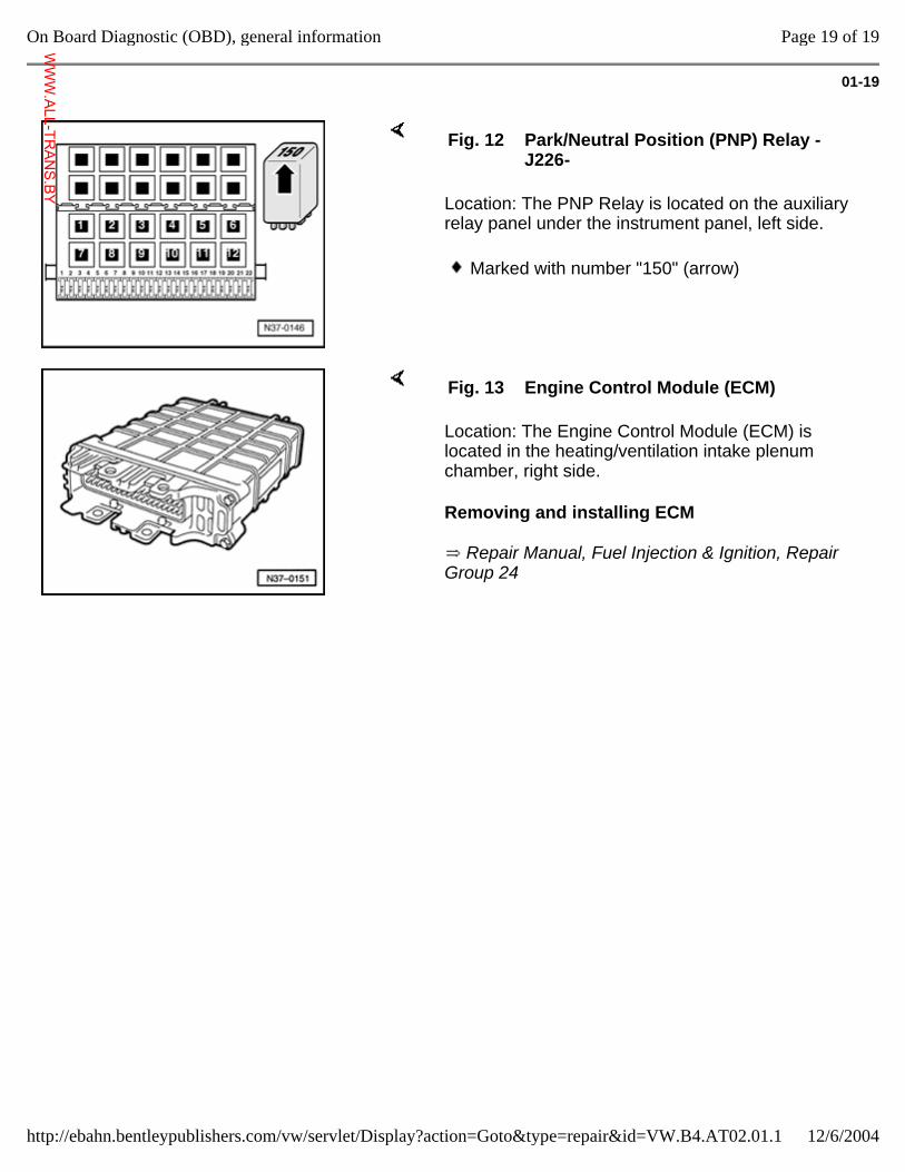
Location: The PNP Relay is located on the auxiliary relay panel under the instrument panel, left side.
Fig. 12 Park/Neutral Position (PNP) Relay -J226-
Marked with number "150" (arrow)
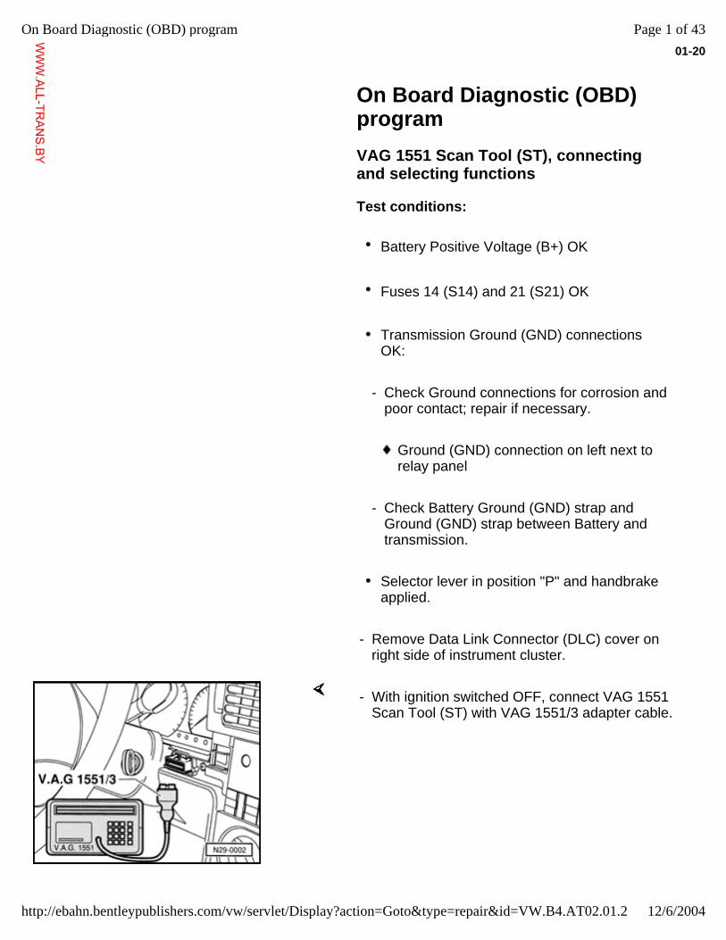
Location: The Engine Control Module (ECM) is located in the heating/ventilation intake plenum chamber, right side.
Removing and installing ECM
Repair Manual, Fuel Injection & Ignition, Repair Group 24
Fig. 13 Engine Control Module (ECM)
Page 19 of 19On Board Diagnostic (OBD), general information
12/6/2004http://ebahn.bentleypublishers.com/vw/servlet/Display?action=Goto&type=repair&id=VW.B4.AT02.01.1
WWW.ALL-TR
ANS.BY
01-20
On Board Diagnostic (OBD) program
VAG 1551 Scan Tool (ST), connecting and selecting functions
Test conditions:
Battery Positive Voltage (B+) OK
Fuses 14 (S14) and 21 (S21) OK
Transmission Ground (GND) connections OK:
- Check Ground connections for corrosion and poor contact; repair if necessary.
Ground (GND) connection on left next to relay panel
- Check Battery Ground (GND) strap and Ground (GND) strap between Battery and transmission.
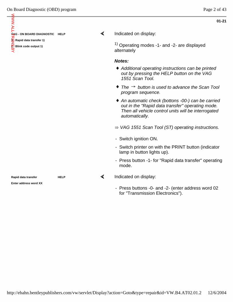
Selector lever in position "P" and handbrake applied.
- Remove Data Link Connector (DLC) cover on right side of instrument cluster.
- With ignition switched OFF, connect VAG 1551 Scan Tool (ST) with VAG 1551/3 adapter cable.
Page 1 of 43On Board Diagnostic (OBD) program
12/6/2004http://ebahn.bentleypublishers.com/vw/servlet/Display?action=Goto&type=repair&id=VW.B4.AT02.01.2
WWW.ALL-TR
ANS.BY
01-21
VAG - ON BOARD DIAGNOSTIC HELP
1 - Rapid data transfer 1)
2 - Blink code output 1)
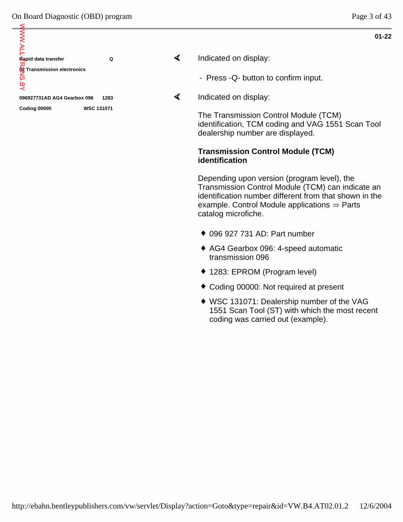
Indicated on display:
1) Operating modes -1- and -2- are displayed alternately
Notes:
VAG 1551 Scan Tool (ST) operating instructions.
Additional operating instructions can be printed out by pressing the HELP button on the VAG 1551 Scan Tool.
The button is used to advance the Scan Tool program sequence.
An automatic check (bottons -00-) can be carried out in the "Rapid data transfer" operating mode. Then all vehicle control units will be interrogated automatically.
- Switch ignition ON.
- Switch printer on with the PRINT button (indicator lamp in button lights up).
- Press button -1- for "Rapid data transfer" operating mode.
Rapid data transfer HELP
Enter address word XX Indicated on display:
- Press buttons -0- and -2- (enter address word 02 for "Transmission Electronics").
Page 2 of 43On Board Diagnostic (OBD) program
12/6/2004http://ebahn.bentleypublishers.com/vw/servlet/Display?action=Goto&type=repair&id=VW.B4.AT02.01.2
WWW.ALL-TR
ANS.BY
01-22
Rapid data transfer Q
02 Transmission electronics Indicated on display:
- Press -Q- button to confirm input.
096927731AD AG4 Gearbox 096 1283
Coding 00000 WSC 131071 Indicated on display:
The Transmission Control Module (TCM) identification, TCM coding and VAG 1551 Scan Tool dealership number are displayed.
Transmission Control Module (TCM) identification
Depending upon version (program level), the Transmission Control Module (TCM) can indicate an identification number different from that shown in the example. Control Module applications Parts catalog microfiche.
096 927 731 AD: Part number
AG4 Gearbox 096: 4-speed automatic transmission 096
1283: EPROM (Program level)
Coding 00000: Not required at present
WSC 131071: Dealership number of the VAG 1551 Scan Tool (ST) with which the most recent coding was carried out (example).
Page 3 of 43On Board Diagnostic (OBD) program
12/6/2004http://ebahn.bentleypublishers.com/vw/servlet/Display?action=Goto&type=repair&id=VW.B4.AT02.01.2
WWW.ALL-TR
ANS.BY
01-23
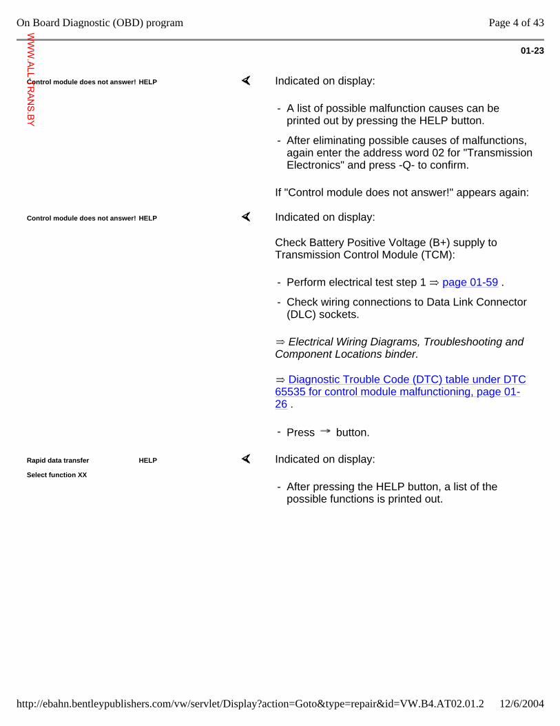
Control module does not answer! HELP Indicated on display:
If "Control module does not answer!" appears again:
- A list of possible malfunction causes can be printed out by pressing the HELP button.
- After eliminating possible causes of malfunctions, again enter the address word 02 for "Transmission Electronics" and press -Q- to confirm.
Control module does not answer! HELP Indicated on display:
Check Battery Positive Voltage (B+) supply to Transmission Control Module (TCM):
Electrical Wiring Diagrams, Troubleshooting and Component Locations binder.
Diagnostic Trouble Code (DTC) table under DTC 65535 for control module malfunctioning, page 01-26 .
- Perform electrical test step 1 page 01-59 .
- Check wiring connections to Data Link Connector (DLC) sockets.
- Press button.
Rapid data transfer HELP
Select function XX Indicated on display:
- After pressing the HELP button, a list of the possible functions is printed out.
Page 4 of 43On Board Diagnostic (OBD) program
12/6/2004http://ebahn.bentleypublishers.com/vw/servlet/Display?action=Goto&type=repair&id=VW.B4.AT02.01.2
WWW.ALL-TR
ANS.BY
01-24
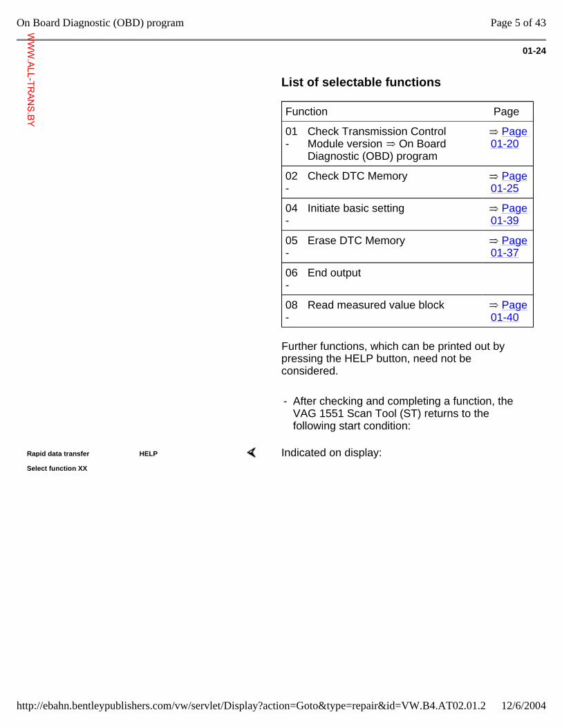
List of selectable functions
Function Page
01 -
Check Transmission Control Module version On Board Diagnostic (OBD) program
Page 01-20
02 -
Check DTC Memory Page 01-25
04 -
Initiate basic setting Page 01-39
05 -
Erase DTC Memory Page 01-37
06 -
End output
08 -
Read measured value block Page 01-40
Further functions, which can be printed out by pressing the HELP button, need not be considered.
- After checking and completing a function, the VAG 1551 Scan Tool (ST) returns to the following start condition:
Rapid data transfer HELP
Select function XX Indicated on display:
Page 5 of 43On Board Diagnostic (OBD) program
12/6/2004http://ebahn.bentleypublishers.com/vw/servlet/Display?action=Goto&type=repair&id=VW.B4.AT02.01.2
WWW.ALL-TR
ANS.BY
01-25
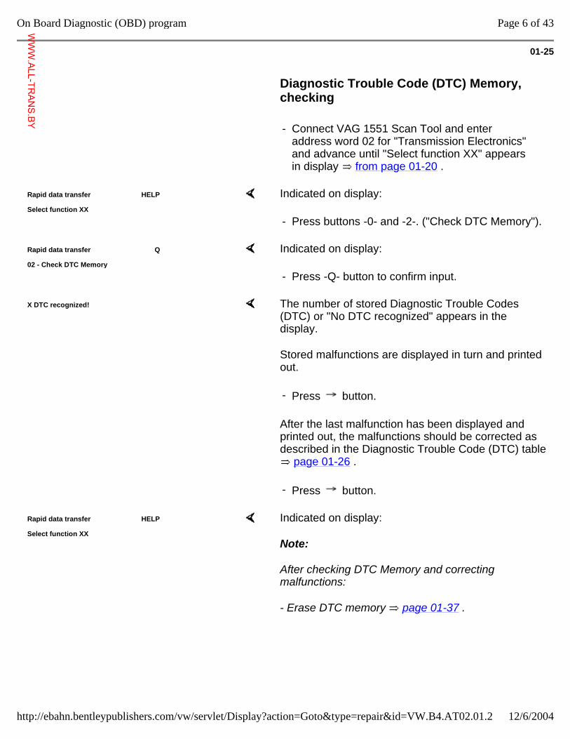
Diagnostic Trouble Code (DTC) Memory, checking
- Connect VAG 1551 Scan Tool and enter address word 02 for "Transmission Electronics" and advance until "Select function XX" appears in display from page 01-20 .
Rapid data transfer HELP
Select function XX Indicated on display:
- Press buttons -0- and -2-. ("Check DTC Memory").
Rapid data transfer Q
02 - Check DTC Memory Indicated on display:
- Press -Q- button to confirm input.
X DTC recognized! The number of stored Diagnostic Trouble Codes (DTC) or "No DTC recognized" appears in the display.
Stored malfunctions are displayed in turn and printed out.
After the last malfunction has been displayed and printed out, the malfunctions should be corrected as described in the Diagnostic Trouble Code (DTC) table
page 01-26 .
- Press button.
- Press button.
Rapid data transfer HELP
Select function XX Indicated on display:
Note:
After checking DTC Memory and correcting malfunctions:
- Erase DTC memory page 01-37 .
Page 6 of 43On Board Diagnostic (OBD) program
12/6/2004http://ebahn.bentleypublishers.com/vw/servlet/Display?action=Goto&type=repair&id=VW.B4.AT02.01.2
WWW.ALL-TR
ANS.BY
01-26
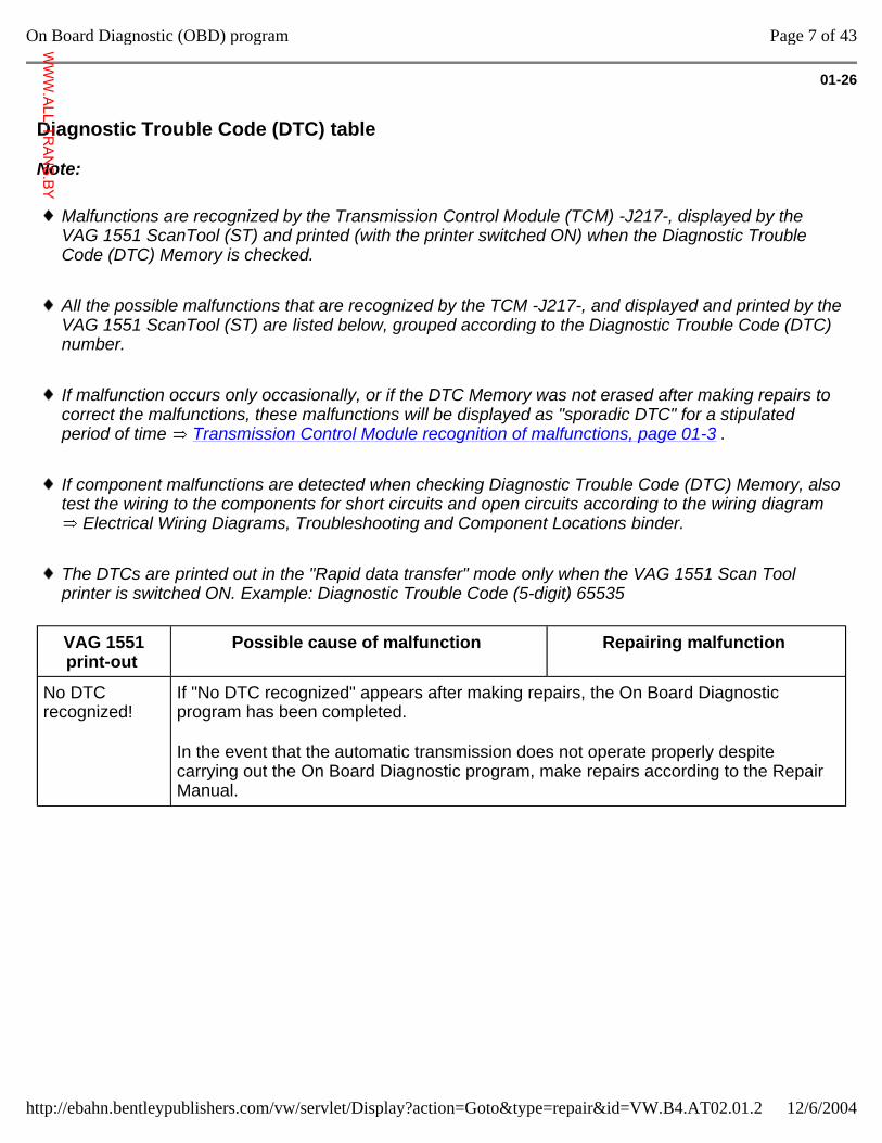
Diagnostic Trouble Code (DTC) table
Note:
Malfunctions are recognized by the Transmission Control Module (TCM) -J217-, displayed by the VAG 1551 ScanTool (ST) and printed (with the printer switched ON) when the Diagnostic Trouble Code (DTC) Memory is checked.
All the possible malfunctions that are recognized by the TCM -J217-, and displayed and printed by the VAG 1551 ScanTool (ST) are listed below, grouped according to the Diagnostic Trouble Code (DTC) number.
If malfunction occurs only occasionally, or if the DTC Memory was not erased after making repairs to correct the malfunctions, these malfunctions will be displayed as "sporadic DTC" for a stipulated period of time Transmission Control Module recognition of malfunctions, page 01-3 .
If component malfunctions are detected when checking Diagnostic Trouble Code (DTC) Memory, also test the wiring to the components for short circuits and open circuits according to the wiring diagram
Electrical Wiring Diagrams, Troubleshooting and Component Locations binder.
The DTCs are printed out in the "Rapid data transfer" mode only when the VAG 1551 Scan Tool printer is switched ON. Example: Diagnostic Trouble Code (5-digit) 65535
VAG 1551 print-out
Possible cause of malfunction Repairing malfunction
No DTC recognized!
If "No DTC recognized" appears after making repairs, the On Board Diagnostic program has been completed.
In the event that the automatic transmission does not operate properly despite carrying out the On Board Diagnostic program, make repairs according to the Repair Manual.
Page 7 of 43On Board Diagnostic (OBD) program
12/6/2004http://ebahn.bentleypublishers.com/vw/servlet/Display?action=Goto&type=repair&id=VW.B4.AT02.01.2
WWW.ALL-TR
ANS.BY
01-27
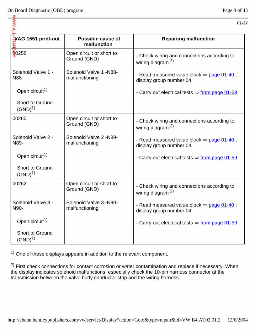
VAG 1551 print-out Possible cause of malfunction
Repairing malfunction
00258 Open circuit or short to Ground (GND) - Check wiring and connections according to
wiring diagram 2)
Solenoid Valve 1 -N88-
Solenoid Valve 1 -N88- malfunctioning - Read measured value block page 01-40 ;
display group number 04
Open circuit1)
Short to Ground (GND)1)
- Carry out electrical tests from page 01-59
00260 Open circuit or short to Ground (GND) - Check wiring and connections according to
wiring diagram 2)
Solenoid Valve 2 -N89-
Solenoid Valve 2 -N89- malfunctioning - Read measured value block page 01-40 ;
display group number 04
Open circuit1)
Short to Ground (GND)1)
- Carry out electrical tests from page 01-59
00262 Open circuit or short to Ground (GND) - Check wiring and connections according to
wiring diagram 2)
Solenoid Valve 3 -N90-
Solenoid Valve 3 -N90- malfunctioning - Read measured value block page 01-40 ;
display group number 04
Open circuit1)
Short to Ground (GND)1)
- Carry out electrical tests from page 01-59
1) One of these displays appears in addition to the relevant component.
2) First check connections for contact corrosion or water contamination and replace if necessary. When the display indicates solenoid malfunctions, especially check the 10-pin harness connector at the transmission between the valve body conductor strip and the wiring harness.
Page 8 of 43On Board Diagnostic (OBD) program
12/6/2004http://ebahn.bentleypublishers.com/vw/servlet/Display?action=Goto&type=repair&id=VW.B4.AT02.01.2
WWW.ALL-TR
ANS.BY

01-28
VAG 1551 print-out Possible cause of malfunction
Repairing malfunction
00264 Open circuit or short to Ground (GND) - Check wiring and connections according to
wiring diagram 2)
Solenoid Valve 4 -N91-
Solenoid Valve 4 -N91- malfunctioning - Read measured value block page 01-40 ;
display group number 04
Open circuit1)
Short to Ground (GND)1)
- Carry out electrical tests from page 01-59
00266 Open circuit or short to Ground (GND) - Check wiring and connections according to
wiring diagram 2)
Solenoid Valve 5 -N92-
Solenoid Valve 5 -N92- malfunctioning - Read measured value block page 01-40 ;
display group number 04
Open circuit1)
Short to Ground (GND)1)
- Carry out electrical tests from page 01-59
00268 Open circuit or short to Ground (GND) - Check wiring and connections according to
wiring diagram 2)
Solenoid Valve 6 -N93-
Solenoid Valve 6 -N93- malfunctioning - Read measured value block page 01-40 ;
display group number 02
Open circuit1)
Short to Ground (GND)1)
- Carry out electrical tests from page 01-59
1) One of these displays appears in addition to the relevant component.
2) First check connections for contact corrosion or water contamination and replace if necessary. When the display indicates solenoid malfunctions, especially check the 10-pin harness connector at the transmission between the valve body conductor strip and the wiring harness.
Page 9 of 43On Board Diagnostic (OBD) program
12/6/2004http://ebahn.bentleypublishers.com/vw/servlet/Display?action=Goto&type=repair&id=VW.B4.AT02.01.2
WWW.ALL-TR
ANS.BY
01-29
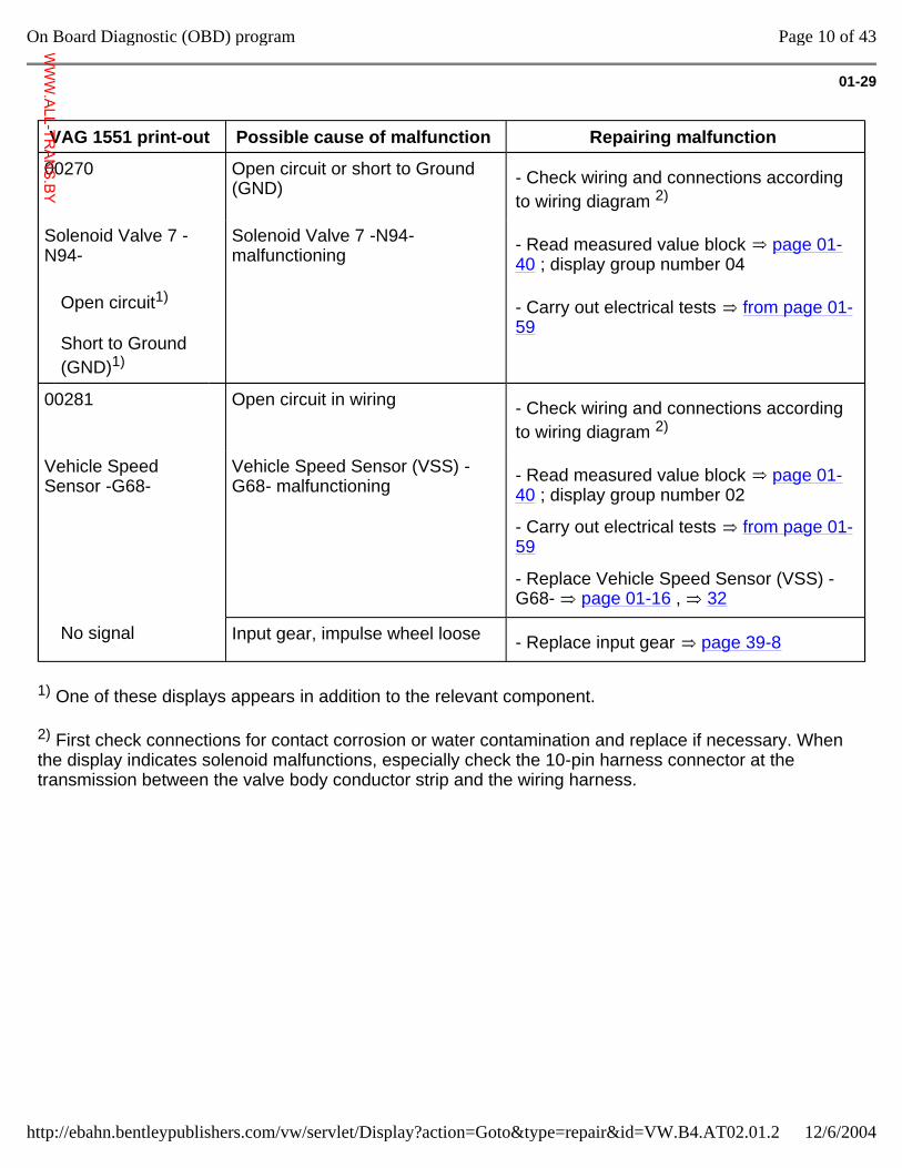
VAG 1551 print-out Possible cause of malfunction Repairing malfunction
00270 Open circuit or short to Ground (GND) - Check wiring and connections according
to wiring diagram 2)
Solenoid Valve 7 -N94-
Solenoid Valve 7 -N94- malfunctioning - Read measured value block page 01-
40 ; display group number 04
Open circuit1)
Short to Ground (GND)1)
- Carry out electrical tests from page 01-59
00281 Open circuit in wiring - Check wiring and connections according to wiring diagram 2)
Vehicle Speed Sensor -G68-
Vehicle Speed Sensor (VSS) -G68- malfunctioning - Read measured value block page 01-
40 ; display group number 02
- Carry out electrical tests from page 01-59
- Replace Vehicle Speed Sensor (VSS) -G68- page 01-16 , 32
No signal Input gear, impulse wheel loose - Replace input gear page 39-8
1) One of these displays appears in addition to the relevant component.
2) First check connections for contact corrosion or water contamination and replace if necessary. When the display indicates solenoid malfunctions, especially check the 10-pin harness connector at the transmission between the valve body conductor strip and the wiring harness.
Page 10 of 43On Board Diagnostic (OBD) program
12/6/2004http://ebahn.bentleypublishers.com/vw/servlet/Display?action=Goto&type=repair&id=VW.B4.AT02.01.2
WWW.ALL-TR
ANS.BY
01-30
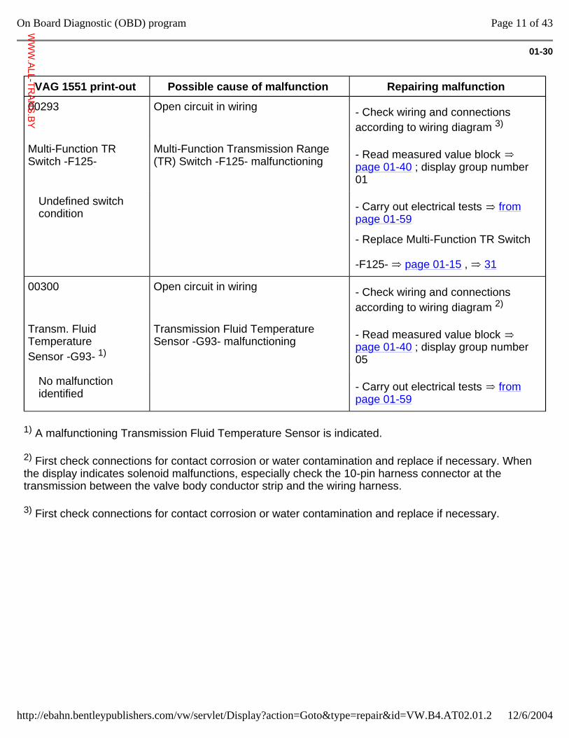
VAG 1551 print-out Possible cause of malfunction Repairing malfunction
00293 Open circuit in wiring - Check wiring and connections according to wiring diagram 3)
Multi-Function TR Switch -F125-
Multi-Function Transmission Range (TR) Switch -F125- malfunctioning - Read measured value block
page 01-40 ; display group number 01
Undefined switch condition
- Carry out electrical tests from page 01-59
- Replace Multi-Function TR Switch -F125- page 01-15 , 31
00300 Open circuit in wiring - Check wiring and connections according to wiring diagram 2)
Transm. Fluid Temperature Sensor -G93- 1)
Transmission Fluid Temperature Sensor -G93- malfunctioning - Read measured value block
page 01-40 ; display group number 05
No malfunction identified
- Carry out electrical tests from page 01-59
1) A malfunctioning Transmission Fluid Temperature Sensor is indicated.
2) First check connections for contact corrosion or water contamination and replace if necessary. When the display indicates solenoid malfunctions, especially check the 10-pin harness connector at the transmission between the valve body conductor strip and the wiring harness.
3) First check connections for contact corrosion or water contamination and replace if necessary.
Page 11 of 43On Board Diagnostic (OBD) program
12/6/2004http://ebahn.bentleypublishers.com/vw/servlet/Display?action=Goto&type=repair&id=VW.B4.AT02.01.2
WWW.ALL-TR
ANS.BY
01-31
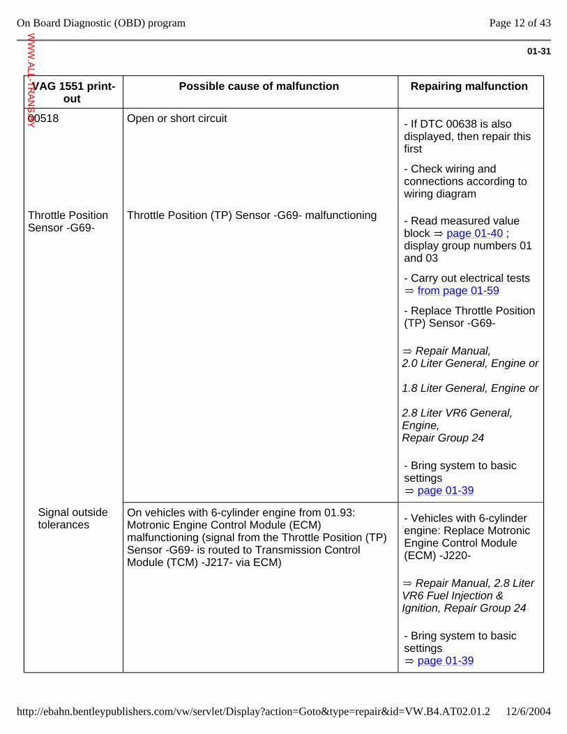
VAG 1551 print-out
Possible cause of malfunction Repairing malfunction
00518 Open or short circuit - If DTC 00638 is also displayed, then repair this first
- Check wiring and connections according to wiring diagram
Throttle Position Sensor -G69-
Throttle Position (TP) Sensor -G69- malfunctioning
Repair Manual, 2.0 Liter General, Engine or 1.8 Liter General, Engine or 2.8 Liter VR6 General, Engine, Repair Group 24
- Read measured value block page 01-40 ; display group numbers 01 and 03
- Carry out electrical tests from page 01-59
- Replace Throttle Position (TP) Sensor -G69-
- Bring system to basic settings
page 01-39
Signal outside tolerances
On vehicles with 6-cylinder engine from 01.93: Motronic Engine Control Module (ECM) malfunctioning (signal from the Throttle Position (TP) Sensor -G69- is routed to Transmission Control Module (TCM) -J217- via ECM)
Repair Manual, 2.8 Liter VR6 Fuel Injection & Ignition, Repair Group 24
- Vehicles with 6-cylinder engine: Replace Motronic Engine Control Module (ECM) -J220-
- Bring system to basic settings
page 01-39
Page 12 of 43On Board Diagnostic (OBD) program
12/6/2004http://ebahn.bentleypublishers.com/vw/servlet/Display?action=Goto&type=repair&id=VW.B4.AT02.01.2
WWW.ALL-TR
ANS.BY
01-32
VAG 1551 print-out Possible cause of malfunction
Repairing malfunction
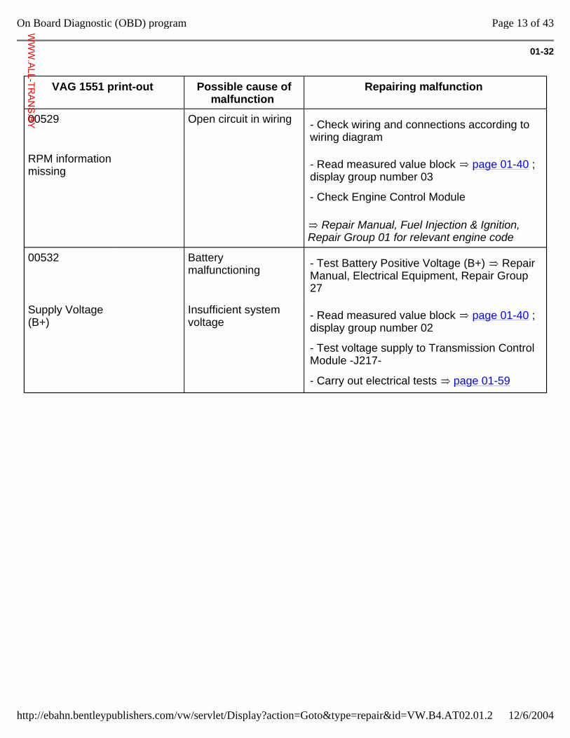
00529 Open circuit in wiring - Check wiring and connections according to wiring diagram
RPM information missing
Repair Manual, Fuel Injection & Ignition, Repair Group 01 for relevant engine code
- Read measured value block page 01-40 ; display group number 03
- Check Engine Control Module
00532 Battery malfunctioning - Test Battery Positive Voltage (B+) Repair
Manual, Electrical Equipment, Repair Group 27
Supply Voltage (B+)
Insufficient system voltage - Read measured value block page 01-40 ;
display group number 02
- Test voltage supply to Transmission Control Module -J217-
- Carry out electrical tests page 01-59
Page 13 of 43On Board Diagnostic (OBD) program
12/6/2004http://ebahn.bentleypublishers.com/vw/servlet/Display?action=Goto&type=repair&id=VW.B4.AT02.01.2
WWW.ALL-TR
ANS.BY
01-33
VAG 1551 print-out Possible cause of malfunction Repairing malfunction
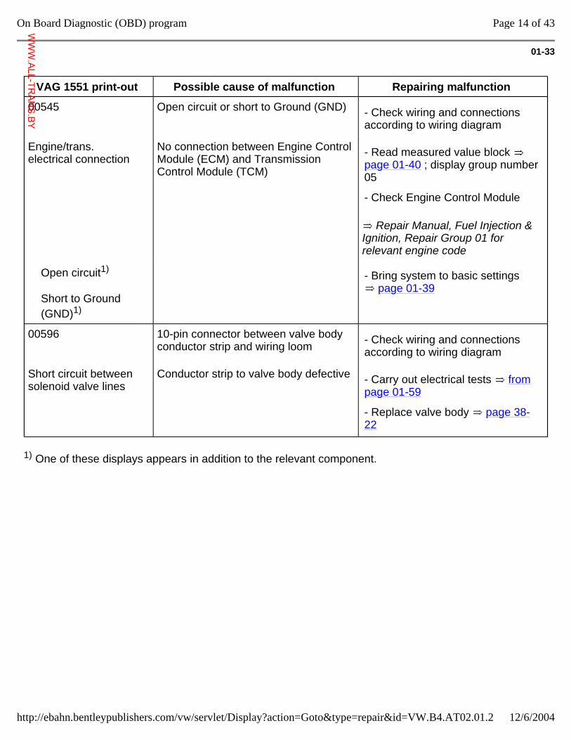
00545 Open circuit or short to Ground (GND) - Check wiring and connections according to wiring diagram
Engine/trans. electrical connection
No connection between Engine Control Module (ECM) and Transmission Control Module (TCM)
Repair Manual, Fuel Injection & Ignition, Repair Group 01 for relevant engine code
- Read measured value block page 01-40 ; display group number 05
- Check Engine Control Module
Open circuit1)
Short to Ground (GND)1)
- Bring system to basic settings page 01-39
00596 10-pin connector between valve body conductor strip and wiring loom - Check wiring and connections
according to wiring diagram
Short circuit between solenoid valve lines
Conductor strip to valve body defective - Carry out electrical tests from page 01-59
- Replace valve body page 38-22
1) One of these displays appears in addition to the relevant component.
Page 14 of 43On Board Diagnostic (OBD) program
12/6/2004http://ebahn.bentleypublishers.com/vw/servlet/Display?action=Goto&type=repair&id=VW.B4.AT02.01.2
WWW.ALL-TR
ANS.BY
01-34
VAG 1551 print-out Possible cause of malfunction Repairing malfunction
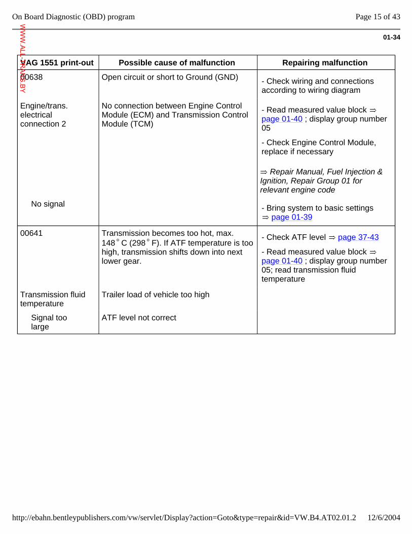
00638 Open circuit or short to Ground (GND) - Check wiring and connections according to wiring diagram
Engine/trans. electrical connection 2
No connection between Engine Control Module (ECM) and Transmission Control Module (TCM)
Repair Manual, Fuel Injection & Ignition, Repair Group 01 for relevant engine code
- Read measured value block page 01-40 ; display group number 05
- Check Engine Control Module, replace if necessary
No signal - Bring system to basic settings page 01-39
00641 Transmission becomes too hot, max. 148 C (298 F). If ATF temperature is too high, transmission shifts down into next lower gear.
- Check ATF level page 37-43
- Read measured value block page 01-40 ; display group number 05; read transmission fluid temperature
Transmission fluid temperature
Trailer load of vehicle too high
Signal too large
ATF level not correct
Page 15 of 43On Board Diagnostic (OBD) program
12/6/2004http://ebahn.bentleypublishers.com/vw/servlet/Display?action=Goto&type=repair&id=VW.B4.AT02.01.2
WWW.ALL-TR
ANS.BY
01-35
VAG 1551 print-out Possible cause of malfunction
Repairing malfunction
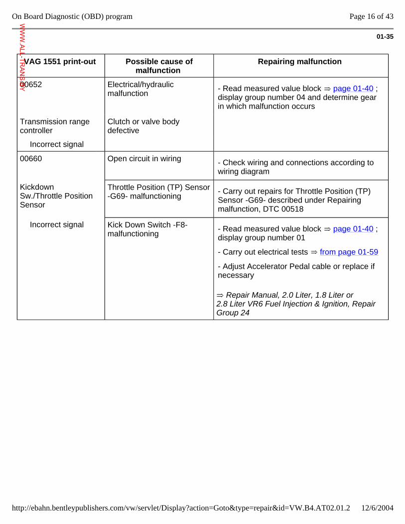
00652 Electrical/hydraulic malfunction - Read measured value block page 01-40 ;
display group number 04 and determine gear in which malfunction occurs
Transmission range controller
Clutch or valve body defective
Incorrect signal
00660 Open circuit in wiring - Check wiring and connections according to wiring diagram
Kickdown Sw./Throttle Position Sensor
Throttle Position (TP) Sensor -G69- malfunctioning - Carry out repairs for Throttle Position (TP)
Sensor -G69- described under Repairing malfunction, DTC 00518
Incorrect signal Kick Down Switch -F8- malfunctioning
Repair Manual, 2.0 Liter, 1.8 Liter or 2.8 Liter VR6 Fuel Injection & Ignition, Repair Group 24
- Read measured value block page 01-40 ; display group number 01
- Carry out electrical tests from page 01-59
- Adjust Accelerator Pedal cable or replace if necessary
Page 16 of 43On Board Diagnostic (OBD) program
12/6/2004http://ebahn.bentleypublishers.com/vw/servlet/Display?action=Goto&type=repair&id=VW.B4.AT02.01.2
WWW.ALL-TR
ANS.BY
01-36
VAG 1551 print-out Possible cause of malfunction Repairing malfunction
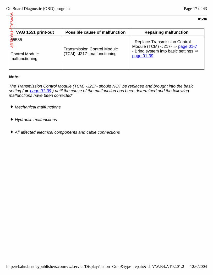
65535
Control Module malfunctioning
Transmission Control Module (TCM) -J217- malfunctioning
- Replace Transmission Control Module (TCM) -J217- page 01-7 - Bring system into basic settings page 01-39
Note:
The Transmission Control Module (TCM) -J217- should NOT be replaced and brought into the basic setting ( page 01-39 ) until the cause of the malfunction has been determined and the following malfunctions have been corrected:
Mechanical malfunctions
Hydraulic malfunctions
All affected electrical components and cable connections
Page 17 of 43On Board Diagnostic (OBD) program
12/6/2004http://ebahn.bentleypublishers.com/vw/servlet/Display?action=Goto&type=repair&id=VW.B4.AT02.01.2
WWW.ALL-TR
ANS.BY
01-37
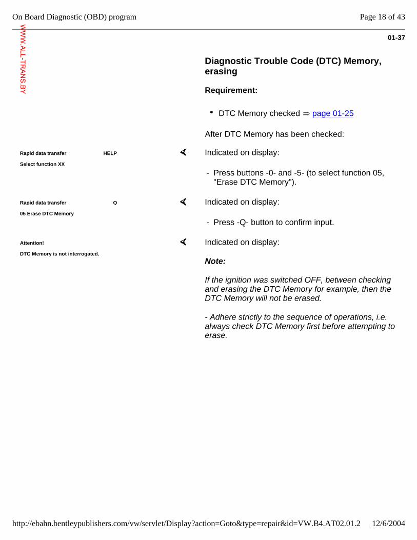
Diagnostic Trouble Code (DTC) Memory, erasing
Requirement:
DTC Memory checked page 01-25
After DTC Memory has been checked:
Rapid data transfer HELP
Select function XX Indicated on display:
- Press buttons -0- and -5- (to select function 05, "Erase DTC Memory").
Rapid data transfer Q
05 Erase DTC Memory Indicated on display:
- Press -Q- button to confirm input.
Attention!
DTC Memory is not interrogated. Indicated on display:
Note:
If the ignition was switched OFF, between checking and erasing the DTC Memory for example, then the DTC Memory will not be erased.
- Adhere strictly to the sequence of operations, i.e. always check DTC Memory first before attempting to erase.
Page 18 of 43On Board Diagnostic (OBD) program
12/6/2004http://ebahn.bentleypublishers.com/vw/servlet/Display?action=Goto&type=repair&id=VW.B4.AT02.01.2
WWW.ALL-TR
ANS.BY
01-38
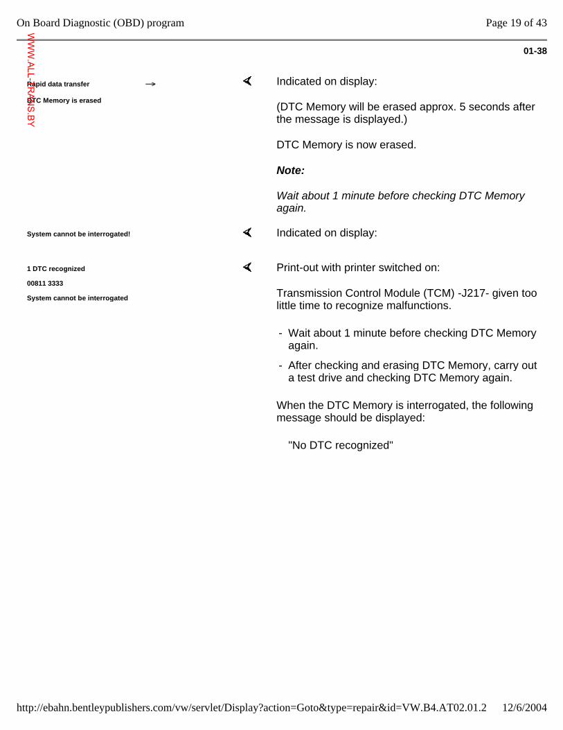
Rapid data transfer
DTC Memory is erased
Indicated on display:
(DTC Memory will be erased approx. 5 seconds after the message is displayed.)
DTC Memory is now erased.
Note:
Wait about 1 minute before checking DTC Memory again.
System cannot be interrogated! Indicated on display:
1 DTC recognized
00811 3333
System cannot be interrogated
Print-out with printer switched on:
Transmission Control Module (TCM) -J217- given too little time to recognize malfunctions.
When the DTC Memory is interrogated, the following message should be displayed:
- Wait about 1 minute before checking DTC Memory again.
- After checking and erasing DTC Memory, carry out a test drive and checking DTC Memory again.
"No DTC recognized"
Page 19 of 43On Board Diagnostic (OBD) program
12/6/2004http://ebahn.bentleypublishers.com/vw/servlet/Display?action=Goto&type=repair&id=VW.B4.AT02.01.2
WWW.ALL-TR
ANS.BY
01-39
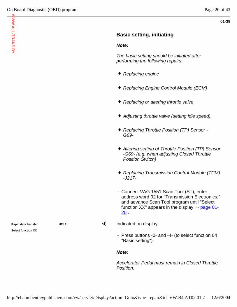
Basic setting, initiating
Note:
The basic setting should be initiated after performing the following repairs:
Replacing engine
Replacing Engine Control Module (ECM)
Replacing or altering throttle valve
Adjusting throttle valve (setting idle speed).
Replacing Throttle Position (TP) Sensor -G69-
Altering setting of Throttle Position (TP) Sensor -G69- (e.g. when adjusting Closed Throttle Position Switch)
Replacing Transmission Control Module (TCM) -J217-
- Connect VAG 1551 Scan Tool (ST), enter address word 02 for "Transmission Electronics," and advance Scan Tool program until "Select function XX" appears in the display page 01-20 .
Rapid data transfer HELP
Select function XX Indicated on display:
Note:
Accelerator Pedal must remain in Closed Throttle Position.
- Press buttons -0- and -4- (to select function 04 "Basic setting").
Page 20 of 43On Board Diagnostic (OBD) program
12/6/2004http://ebahn.bentleypublishers.com/vw/servlet/Display?action=Goto&type=repair&id=VW.B4.AT02.01.2
WWW.ALL-TR
ANS.BY
01-40
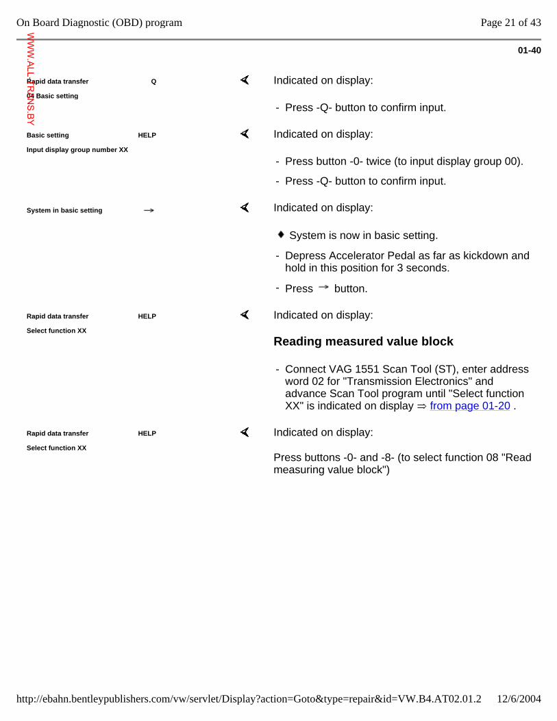
Rapid data transfer Q
04 Basic setting Indicated on display:
- Press -Q- button to confirm input.
Basic setting HELP
Input display group number XX Indicated on display:
- Press button -0- twice (to input display group 00).
- Press -Q- button to confirm input.
System in basic setting Indicated on display:
System is now in basic setting.
- Depress Accelerator Pedal as far as kickdown and hold in this position for 3 seconds.
- Press button.
Rapid data transfer HELP
Select function XX Indicated on display:
Reading measured value block
- Connect VAG 1551 Scan Tool (ST), enter address word 02 for "Transmission Electronics" and advance Scan Tool program until "Select function XX" is indicated on display from page 01-20 .
Rapid data transfer HELP
Select function XX Indicated on display:
Press buttons -0- and -8- (to select function 08 "Read measuring value block")
Page 21 of 43On Board Diagnostic (OBD) program
12/6/2004http://ebahn.bentleypublishers.com/vw/servlet/Display?action=Goto&type=repair&id=VW.B4.AT02.01.2
WWW.ALL-TR
ANS.BY
01-41
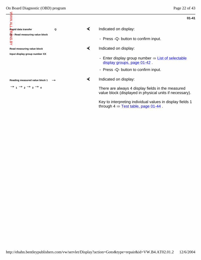
Rapid data transfer Q
08 - Read measuring value block Indicated on display:
- Press -Q- button to confirm input.
Read measuring value block
Input display group number XX Indicated on display:
- Enter display group number List of selectable display groups, page 01-42 .
- Press -Q- button to confirm input.
Reading measured value block 1
1 2 3 4
Indicated on display:
There are always 4 display fields in the measured value block (displayed in physical units if necessary).
Key to interpreting individual values in display fields 1 through 4 Test table, page 01-44 .
Page 22 of 43On Board Diagnostic (OBD) program
12/6/2004http://ebahn.bentleypublishers.com/vw/servlet/Display?action=Goto&type=repair&id=VW.B4.AT02.01.2
WWW.ALL-TR
ANS.BY
01-42
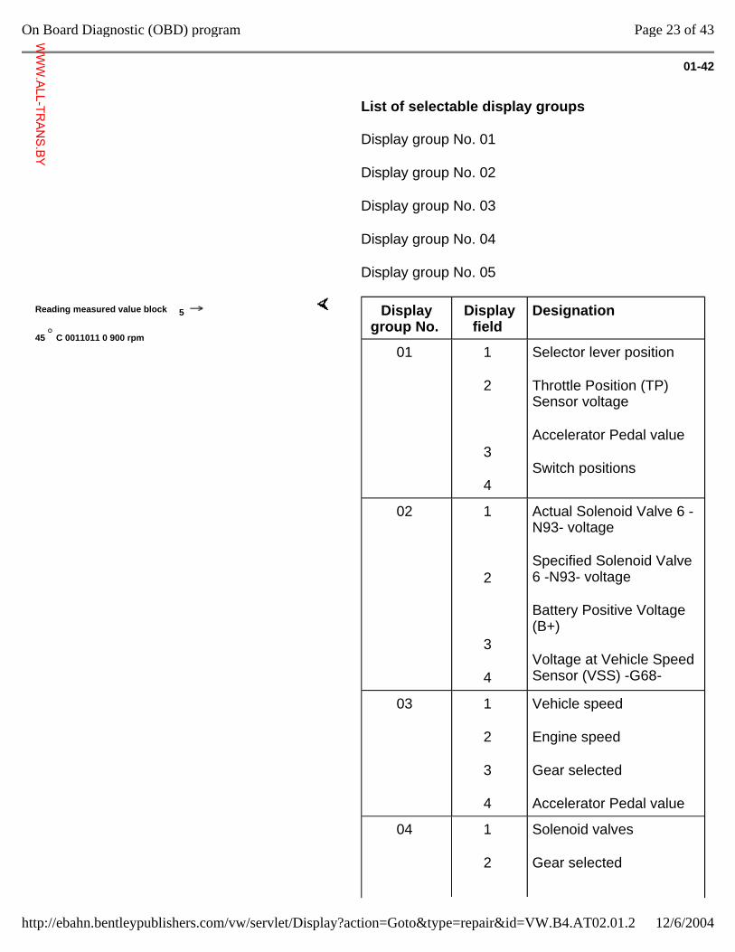
List of selectable display groups
Display group No. 01
Display group No. 02
Display group No. 03
Display group No. 04
Display group No. 05
Reading measured value block 5
45 C 0011011 0 900 rpm
Display group No.
Display field
Designation
01 1
2
3
4
Selector lever position
Throttle Position (TP) Sensor voltage
Accelerator Pedal value
Switch positions
02 1
2
3
4
Actual Solenoid Valve 6 -N93- voltage
Specified Solenoid Valve 6 -N93- voltage
Battery Positive Voltage (B+)
Voltage at Vehicle Speed Sensor (VSS) -G68-
03 1
2
3
4
Vehicle speed
Engine speed
Gear selected
Accelerator Pedal value
04 1
2
Solenoid valves
Gear selected
Page 23 of 43On Board Diagnostic (OBD) program
12/6/2004http://ebahn.bentleypublishers.com/vw/servlet/Display?action=Goto&type=repair&id=VW.B4.AT02.01.2
WWW.ALL-TR
ANS.BY
.
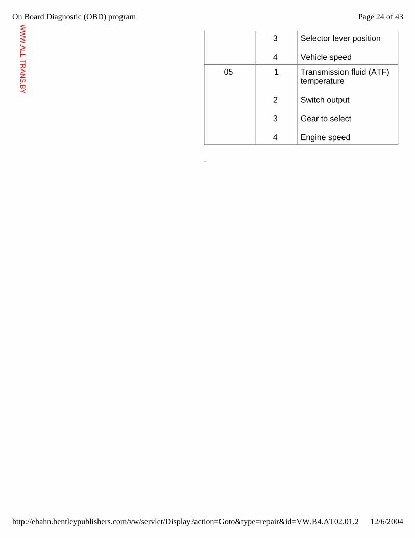
3
4
Selector lever position
Vehicle speed
05 1
2
3
4
Transmission fluid (ATF) temperature
Switch output
Gear to select
Engine speed
Page 24 of 43On Board Diagnostic (OBD) program
12/6/2004http://ebahn.bentleypublishers.com/vw/servlet/Display?action=Goto&type=repair&id=VW.B4.AT02.01.2
WWW.ALL-TR
ANS.BY
01-43
Reading measured value block 4
1001 00 0 P 0 km/h
Notes: If the printer is switched ON, the current display is printed out on the log.
If the values in all the display fields are as specified:
- Press button .
Rapid data transfer HELP
Select function XX Indicated on display:
Page 25 of 43On Board Diagnostic (OBD) program
12/6/2004http://ebahn.bentleypublishers.com/vw/servlet/Display?action=Goto&type=repair&id=VW.B4.AT02.01.2
WWW.ALL-TR
ANS.BY
01-44
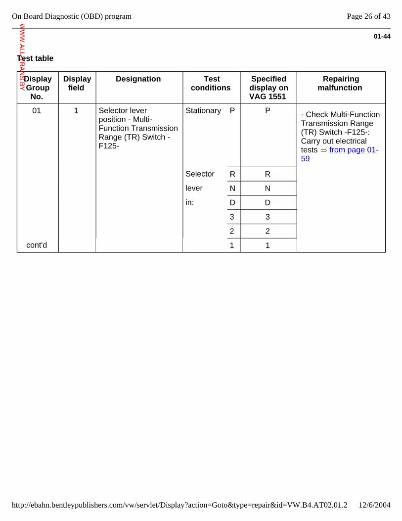
Test table
Display Group
No.
Display field
Designation Test conditions
Specified display on VAG 1551
Repairing malfunction
01 1 Selector lever position - Multi-Function Transmission Range (TR) Switch -F125-
Stationary P P
- Check Multi-Function Transmission Range (TR) Switch -F125-: Carry out electrical tests from page 01-59
Selector R R
lever N N
in: D D
3 3
2 2
cont'd 1 1
Page 26 of 43On Board Diagnostic (OBD) program
12/6/2004http://ebahn.bentleypublishers.com/vw/servlet/Display?action=Goto&type=repair&id=VW.B4.AT02.01.2
WWW.ALL-TR
ANS.BY
01-45
Display Group No.
Display field
Designation Test conditions Specified display on VAG 1551
Repairing malfunction
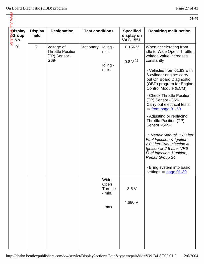
01 2 Voltage of Throttle Position (TP) Sensor -G69-
Stationary Idling - min.
Idling - max.
0.156 V
0.8 V 1)
When accelerating from idle to Wide Open Throttle, voltage value increases constantly
Repair Manual, 1.8 Liter Fuel Injection & Ignition, 2.0 Liter Fuel Injection & Ignition or 2.8 Liter VR6 Fuel Injection &Ignition, Repair Group 24
- Vehicles from 01.93 with 6-cylinder engine: carry out On Board Diagnostic (OBD) program for Engine Control Module (ECM)
- Check Throttle Position (TP) Sensor -G69-: Carry out electrical tests
from page 01-59
- Adjusting or replacing Throttle Position (TP) Sensor -G69-:
- Bring system into basic settings page 01-39
Wide Open Throttle - min.
- max.
3.5 V
4.680 V
Page 27 of 43On Board Diagnostic (OBD) program
12/6/2004http://ebahn.bentleypublishers.com/vw/servlet/Display?action=Goto&type=repair&id=VW.B4.AT02.01.2
WWW.ALL-TR
ANS.BY
cont'd
1) Engine with Mono-Motronic: Engine Coolant Temperature (ECT) min. 80 C (176 F).
Page 28 of 43On Board Diagnostic (OBD) program
12/6/2004http://ebahn.bentleypublishers.com/vw/servlet/Display?action=Goto&type=repair&id=VW.B4.AT02.01.2
WWW.ALL-TR
ANS.BY
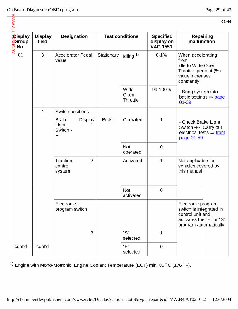
01-46
Display Group No.
Display field
Designation Test conditions Specified display on VAG 1551
Repairing malfunction
01 3 Accelerator Pedal value
Stationary Idling 1) 0-1% When accelerating from idle to Wide Open Throttle, percent (%) value increases constantly
Wide Open Throttle
99-100% - Bring system into basic settings page 01-39
4 Switch positions
Brake Light Switch -F-
Display 1
Brake Operated 1 - Check Brake Light Switch -F-: Carry out electrical tests from page 01-59
Not operated
0
Traction control system
2 Activated 1 Not applicable for vehicles covered by this manual
Not activated
0
Electronic program switch
Electronic program switch is integrated in control unit and activates the "E" or "S" program automatically
3 "S" selected
1
cont'd cont'd "E" selected
0
1) Engine with Mono-Motronic: Engine Coolant Temperature (ECT) min. 80 C (176 F).
Page 29 of 43On Board Diagnostic (OBD) program
12/6/2004http://ebahn.bentleypublishers.com/vw/servlet/Display?action=Goto&type=repair&id=VW.B4.AT02.01.2
WWW.ALL-TR
ANS.BY
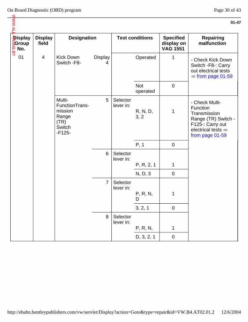
01-47
Display Group
No.
Display field
Designation Test conditions Specified display on VAG 1551
Repairing malfunction
01 4 Kick Down Switch -F8-
Display 4
Operated 1 - Check Kick Down Switch -F8-: Carry out electrical tests
from page 01-59
Not operated
0
Multi- FunctionTrans- mission Range (TR) Switch -F125-
5 Selector lever in:
R, N, D, 3, 2
1
- Check Multi-Function Transmission Range (TR) Switch -F125-: Carry out electrical tests from page 01-59
P, 1 0
6 Selector lever in:
P, R, 2, 1
1
N, D, 3 0
7 Selector lever in:
P, R, N, D
1
3, 2, 1 0
8 Selector lever in:
P, R, N,
1
D, 3, 2, 1 0
Page 30 of 43On Board Diagnostic (OBD) program
12/6/2004http://ebahn.bentleypublishers.com/vw/servlet/Display?action=Goto&type=repair&id=VW.B4.AT02.01.2
WWW.ALL-TR
ANS.BY
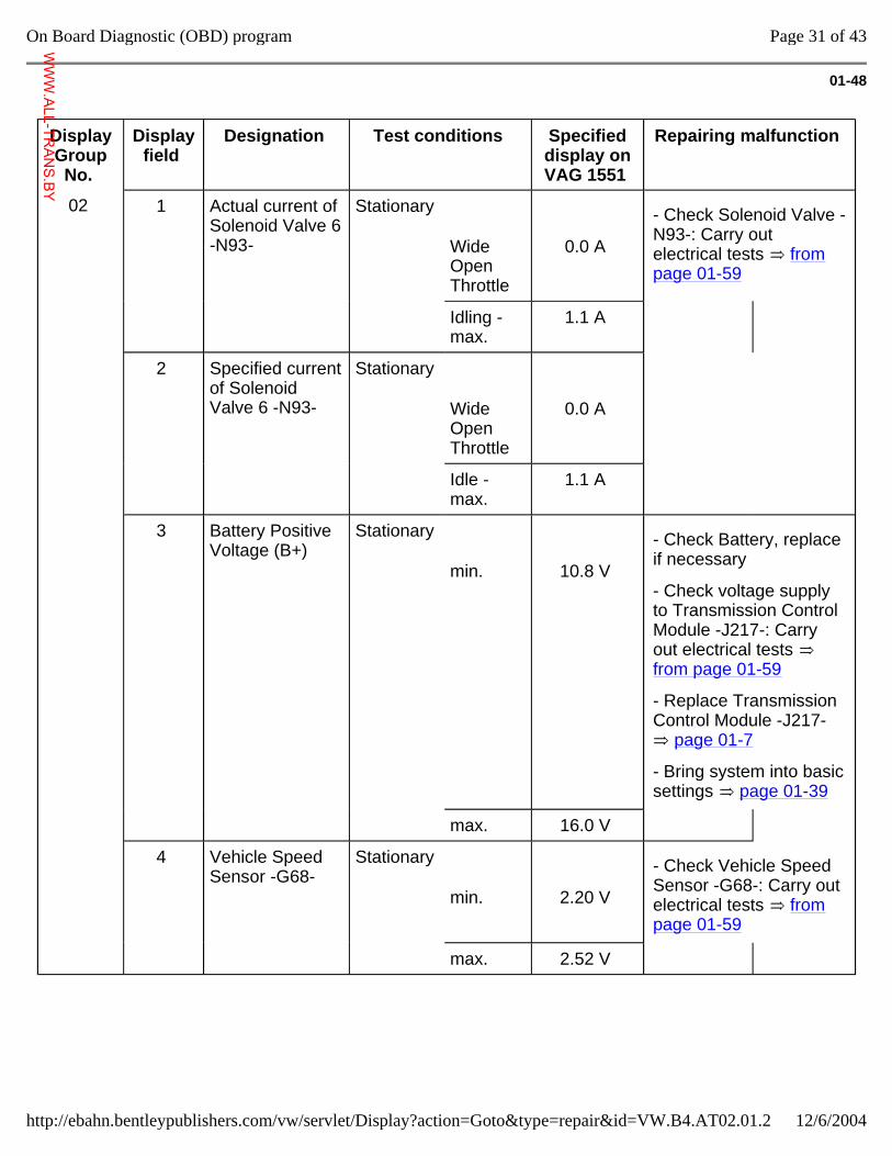
01-48
Display Group
No.
Display field
Designation Test conditions Specified display on VAG 1551
Repairing malfunction
02 1 Actual current of Solenoid Valve 6 -N93-
Stationary
Wide Open Throttle
0.0 A
- Check Solenoid Valve -N93-: Carry out electrical tests from page 01-59
Idling - max.
1.1 A
2 Specified current of Solenoid Valve 6 -N93-
Stationary
Wide Open Throttle
0.0 A
Idle - max.
1.1 A
3 Battery Positive Voltage (B+)
Stationary
min.
10.8 V
- Check Battery, replace if necessary
- Check voltage supply to Transmission Control Module -J217-: Carry out electrical tests from page 01-59
- Replace Transmission Control Module -J217-
page 01-7
- Bring system into basic settings page 01-39
max. 16.0 V
4 Vehicle Speed Sensor -G68-
Stationary
min.
2.20 V
- Check Vehicle Speed Sensor -G68-: Carry out electrical tests from page 01-59
max. 2.52 V
Page 31 of 43On Board Diagnostic (OBD) program
12/6/2004http://ebahn.bentleypublishers.com/vw/servlet/Display?action=Goto&type=repair&id=VW.B4.AT02.01.2
WWW.ALL-TR
ANS.BY
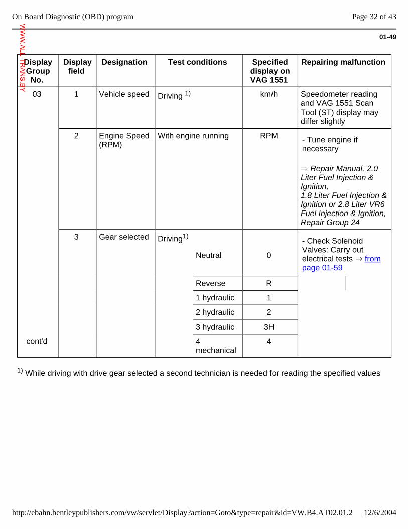
01-49
Display Group
No.
Display field
Designation Test conditions Specified display on VAG 1551
Repairing malfunction
03
1 Vehicle speed Driving 1) km/h Speedometer reading and VAG 1551 Scan Tool (ST) display may differ slightly
2 Engine Speed (RPM)
With engine running RPM
Repair Manual, 2.0 Liter Fuel Injection & Ignition, 1.8 Liter Fuel Injection & Ignition or 2.8 Liter VR6 Fuel Injection & Ignition, Repair Group 24
- Tune engine if necessary
3 Gear selected Driving1)
Neutral
0
- Check Solenoid Valves: Carry out electrical tests from page 01-59
Reverse R
1 hydraulic 1
2 hydraulic 2
3 hydraulic 3H
cont'd 4 mechanical
4
1) While driving with drive gear selected a second technician is needed for reading the specified values
Page 32 of 43On Board Diagnostic (OBD) program
12/6/2004http://ebahn.bentleypublishers.com/vw/servlet/Display?action=Goto&type=repair&id=VW.B4.AT02.01.2
WWW.ALL-TR
ANS.BY
01-50
Display Group
No.
Display field
Designation Test conditions Specified display on VAG 1551
Repairing malfunction
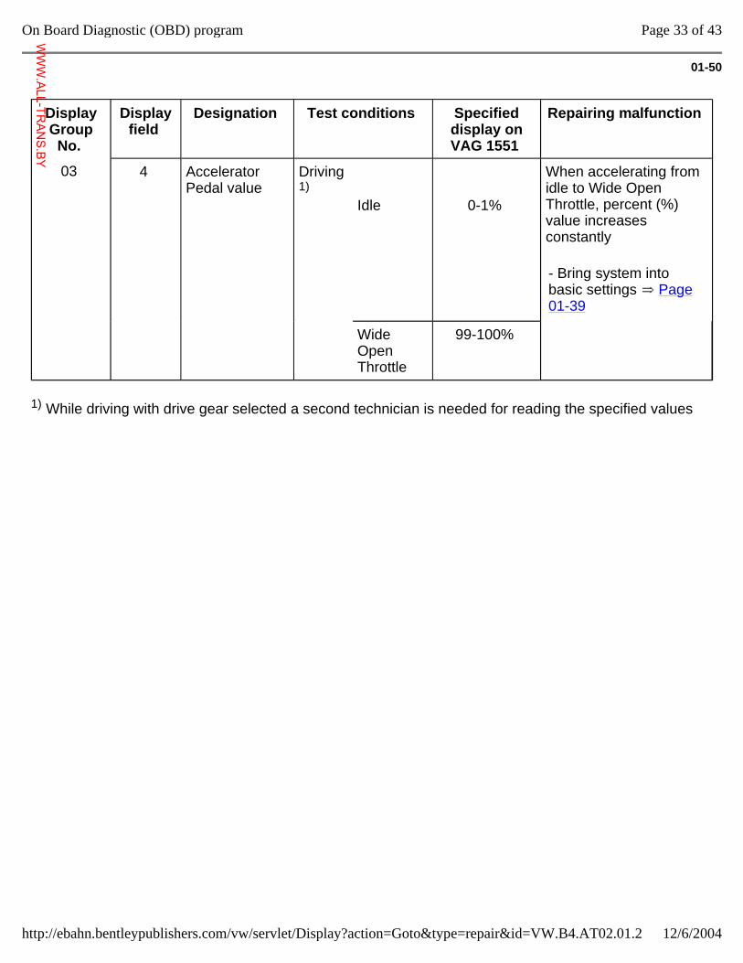
03
4 Accelerator Pedal value
Driving 1)
Idle
0-1%
When accelerating from idle to Wide Open Throttle, percent (%) value increases constantly
- Bring system into basic settings Page 01-39
Wide Open Throttle
99-100%
1) While driving with drive gear selected a second technician is needed for reading the specified values
Page 33 of 43On Board Diagnostic (OBD) program
12/6/2004http://ebahn.bentleypublishers.com/vw/servlet/Display?action=Goto&type=repair&id=VW.B4.AT02.01.2
WWW.ALL-TR
ANS.BY
01-51
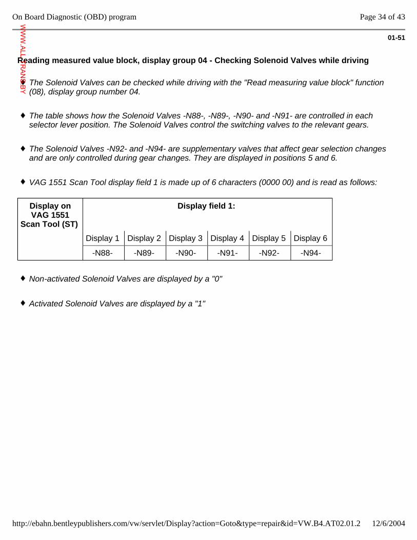
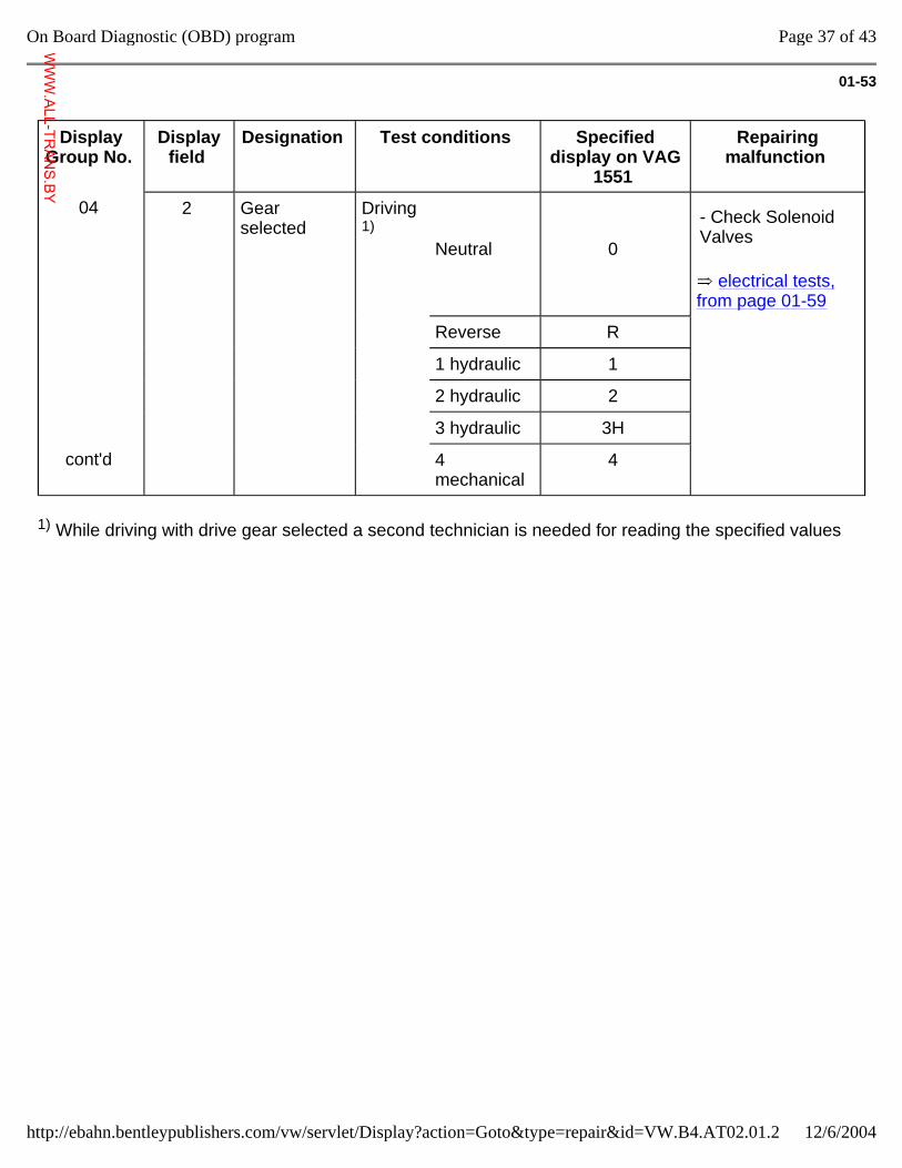
Reading measured value block, display group 04 - Checking Solenoid Valves while driving
The Solenoid Valves can be checked while driving with the "Read measuring value block" function (08), display group number 04.
The table shows how the Solenoid Valves -N88-, -N89-, -N90- and -N91- are controlled in each selector lever position. The Solenoid Valves control the switching valves to the relevant gears.
The Solenoid Valves -N92- and -N94- are supplementary valves that affect gear selection changes and are only controlled during gear changes. They are displayed in positions 5 and 6.
VAG 1551 Scan Tool display field 1 is made up of 6 characters (0000 00) and is read as follows:
Display on VAG 1551
Scan Tool (ST)
Display field 1:
Display 1 Display 2 Display 3 Display 4 Display 5 Display 6
-N88- -N89- -N90- -N91- -N92- -N94-
Non-activated Solenoid Valves are displayed by a "0"
Activated Solenoid Valves are displayed by a "1"
Page 34 of 43On Board Diagnostic (OBD) program
12/6/2004http://ebahn.bentleypublishers.com/vw/servlet/Display?action=Goto&type=repair&id=VW.B4.AT02.01.2
WWW.ALL-TR
ANS.BY
01-52
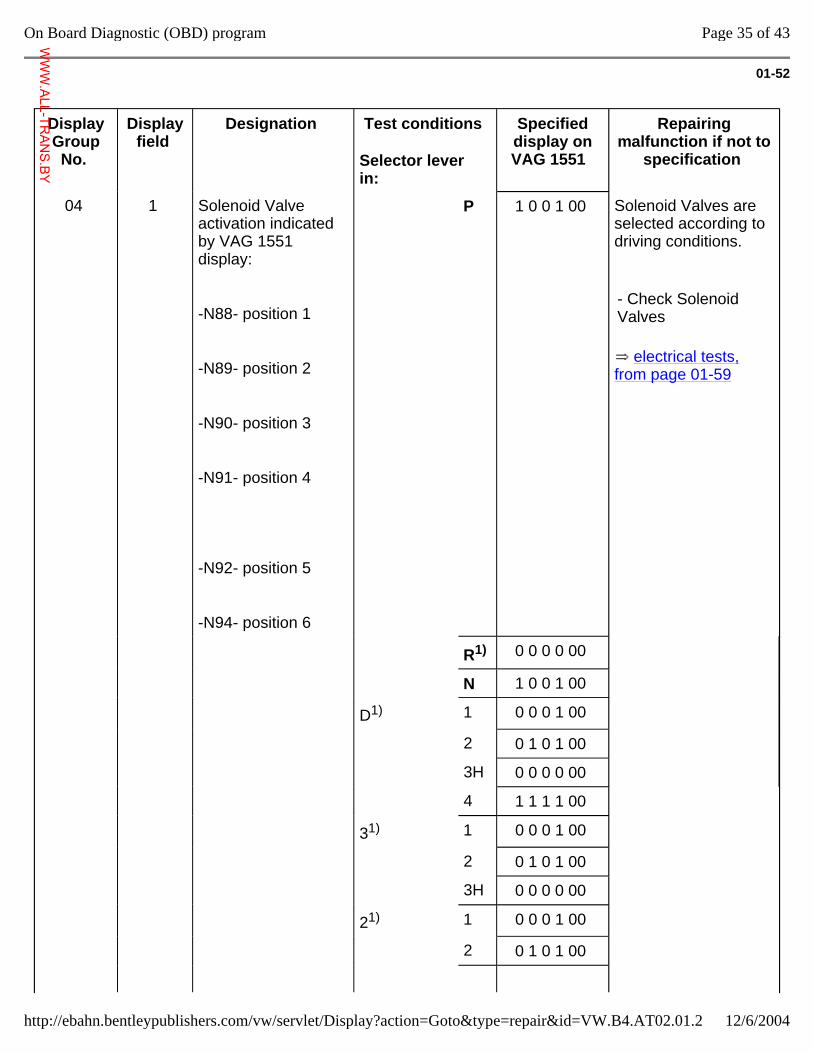
Display Group No.
Display field
Designation Test conditions
Selector lever in:
Specified display on VAG 1551
Repairing malfunction if not to
specification
04 1 Solenoid Valve activation indicated by VAG 1551 display:
-N88- position 1
-N89- position 2
-N90- position 3
-N91- position 4
-N92- position 5
-N94- position 6
P 1 0 0 1 00 Solenoid Valves are selected according to driving conditions.
electrical tests, from page 01-59
- Check Solenoid Valves
R1) 0 0 0 0 00
N 1 0 0 1 00
D1) 1 0 0 0 1 00
2 0 1 0 1 00
3H 0 0 0 0 00
4 1 1 1 1 00
31) 1 0 0 0 1 00
2 0 1 0 1 00
3H 0 0 0 0 00
21) 1 0 0 0 1 00
2 0 1 0 1 00
Page 35 of 43On Board Diagnostic (OBD) program
12/6/2004http://ebahn.bentleypublishers.com/vw/servlet/Display?action=Goto&type=repair&id=VW.B4.AT02.01.2
WWW.ALL-TR
ANS.BY
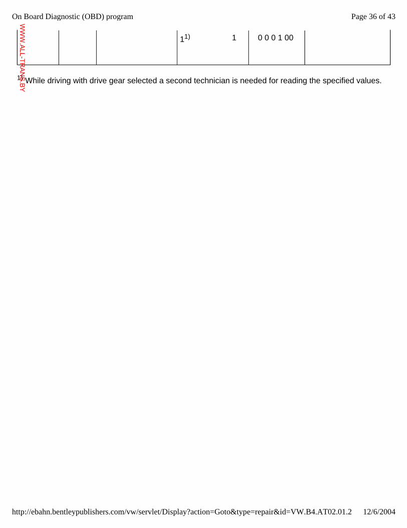
11)
1 0 0 0 1 00
1) While driving with drive gear selected a second technician is needed for reading the specified values.
Page 36 of 43On Board Diagnostic (OBD) program
12/6/2004http://ebahn.bentleypublishers.com/vw/servlet/Display?action=Goto&type=repair&id=VW.B4.AT02.01.2
WWW.ALL-TR
ANS.BY
01-53
Display Group No.
Display field
Designation Test conditions Specified display on VAG
1551
Repairing malfunction
04 2 Gear selected
Driving 1)
Neutral
0
electrical tests, from page 01-59
- Check Solenoid Valves
Reverse R
1 hydraulic 1
2 hydraulic 2
3 hydraulic 3H
cont'd 4 mechanical
4
1) While driving with drive gear selected a second technician is needed for reading the specified values
Page 37 of 43On Board Diagnostic (OBD) program
12/6/2004http://ebahn.bentleypublishers.com/vw/servlet/Display?action=Goto&type=repair&id=VW.B4.AT02.01.2
WWW.ALL-TR
ANS.BY
01-54
Display Group
No.
Display field
Designation Test conditions
Specified display on VAG 1551
Repairing malfunction
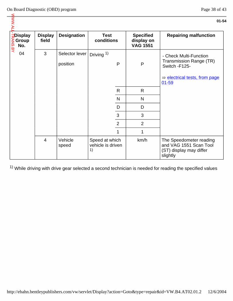
04 3 Selector lever position
Driving 1)
P
P
electrical tests, from page 01-59
- Check Multi-Function Transmission Range (TR) Switch -F125-
R R
N N
D D
3 3
2 2
1 1
4 Vehicle speed
Speed at which vehicle is driven 1)
km/h The Speedometer reading and VAG 1551 Scan Tool (ST) display may differ slightly
1) While driving with drive gear selected a second technician is needed for reading the specified values
Page 38 of 43On Board Diagnostic (OBD) program
12/6/2004http://ebahn.bentleypublishers.com/vw/servlet/Display?action=Goto&type=repair&id=VW.B4.AT02.01.2
WWW.ALL-TR
ANS.BY
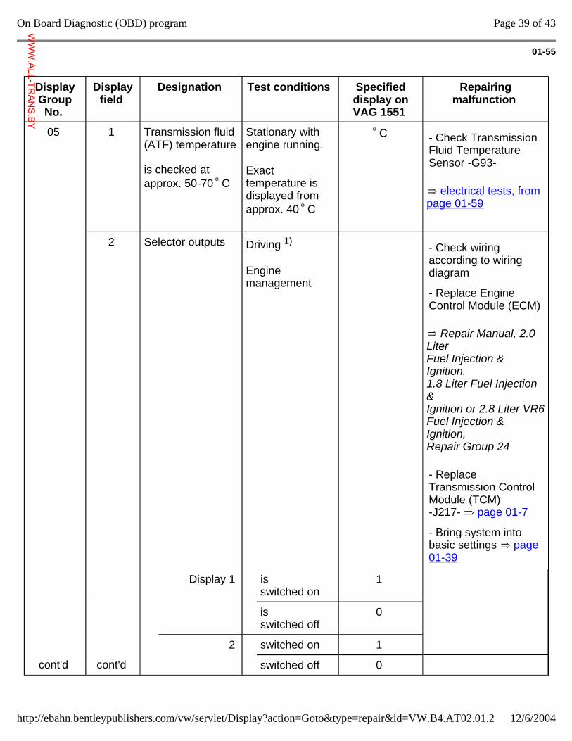
01-55
Display Group No.
Display field
Designation Test conditions Specified display on VAG 1551
Repairing malfunction
05 1 Transmission fluid (ATF) temperature is checked at approx. 50-70 C
Stationary with engine running.
Exact temperature is displayed from approx. 40 C
C
electrical tests, from page 01-59
- Check Transmission Fluid Temperature Sensor -G93-
2 Selector outputs Driving 1)
Engine management
Repair Manual, 2.0 Liter Fuel Injection & Ignition, 1.8 Liter Fuel Injection & Ignition or 2.8 Liter VR6 Fuel Injection & Ignition, Repair Group 24
- Check wiring according to wiring diagram
- Replace Engine Control Module (ECM)
- Replace Transmission Control Module (TCM) -J217- page 01-7
- Bring system into basic settings page 01-39
Display 1 is switched on
1
is switched off
0
2 switched on 1
cont'd cont'd switched off 0
Page 39 of 43On Board Diagnostic (OBD) program
12/6/2004http://ebahn.bentleypublishers.com/vw/servlet/Display?action=Goto&type=repair&id=VW.B4.AT02.01.2
WWW.ALL-TR
ANS.BY
1) While driving with drive gear selected a second technician is needed for reading the specified values
Page 40 of 43On Board Diagnostic (OBD) program
12/6/2004http://ebahn.bentleypublishers.com/vw/servlet/Display?action=Goto&type=repair&id=VW.B4.AT02.01.2
WWW.ALL-TR
ANS.BY
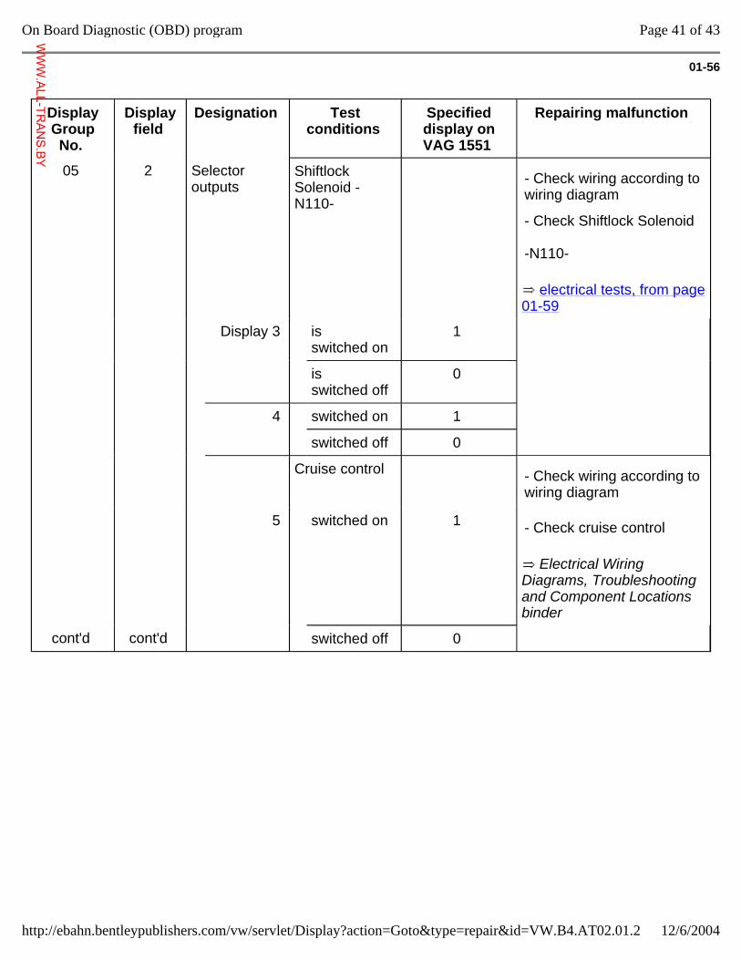
01-56
Display Group No.
Display field
Designation Test conditions
Specified display on VAG 1551
Repairing malfunction
05 2 Selector outputs
Shiftlock Solenoid -N110-
electrical tests, from page 01-59
- Check wiring according to wiring diagram
- Check Shiftlock Solenoid -N110-
Display 3 is switched on
1
is switched off
0
4 switched on 1
switched off 0
Cruise control - Check wiring according to wiring diagram
5 switched on 1
Electrical Wiring Diagrams, Troubleshooting and Component Locations binder
- Check cruise control
cont'd cont'd switched off 0
Page 41 of 43On Board Diagnostic (OBD) program
12/6/2004http://ebahn.bentleypublishers.com/vw/servlet/Display?action=Goto&type=repair&id=VW.B4.AT02.01.2
WWW.ALL-TR
ANS.BY
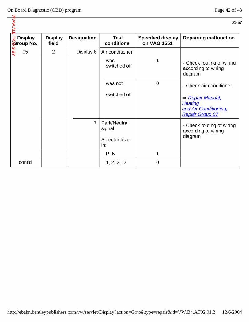
01-57
Display Group No.
Display field
Designation Test conditions
Specified display on VAG 1551
Repairing malfunction
05 2 Display 6 Air conditioner
was switched off
1 - Check routing of wiring according to wiring diagram
was not
switched off
0
Repair Manual, Heating and Air Conditioning, Repair Group 87
- Check air conditioner
7 Park/Neutral signal
Selector lever in:
- Check routing of wiring according to wiring diagram
P, N 1
cont'd 1, 2, 3, D 0
Page 42 of 43On Board Diagnostic (OBD) program
12/6/2004http://ebahn.bentleypublishers.com/vw/servlet/Display?action=Goto&type=repair&id=VW.B4.AT02.01.2
WWW.ALL-TR
ANS.BY
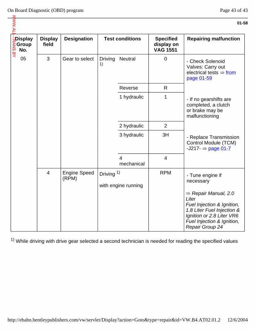
01-58
Display Group No.
Display field
Designation Test conditions Specified display on VAG 1551
Repairing malfunction
05 3 Gear to select Driving 1)
Neutral 0 - Check Solenoid Valves: Carry out electrical tests from page 01-59
Reverse R
1 hydraulic 1 - If no gearshifts are completed, a clutch or brake may be malfunctioning
2 hydraulic 2
3 hydraulic 3H - Replace Transmission Control Module (TCM) -J217- page 01-7
4 mechanical
4
4 Engine Speed (RPM)
Driving 1)
with engine running
RPM
Repair Manual, 2.0 Liter Fuel Injection & Ignition, 1.8 Liter Fuel Injection & Ignition or 2.8 Liter VR6 Fuel Injection & Ignition, Repair Group 24
- Tune engine if necessary
1) While driving with drive gear selected a second technician is needed for reading the specified values
Page 43 of 43On Board Diagnostic (OBD) program
12/6/2004http://ebahn.bentleypublishers.com/vw/servlet/Display?action=Goto&type=repair&id=VW.B4.AT02.01.2
WWW.ALL-TR
ANS.BY
01-59
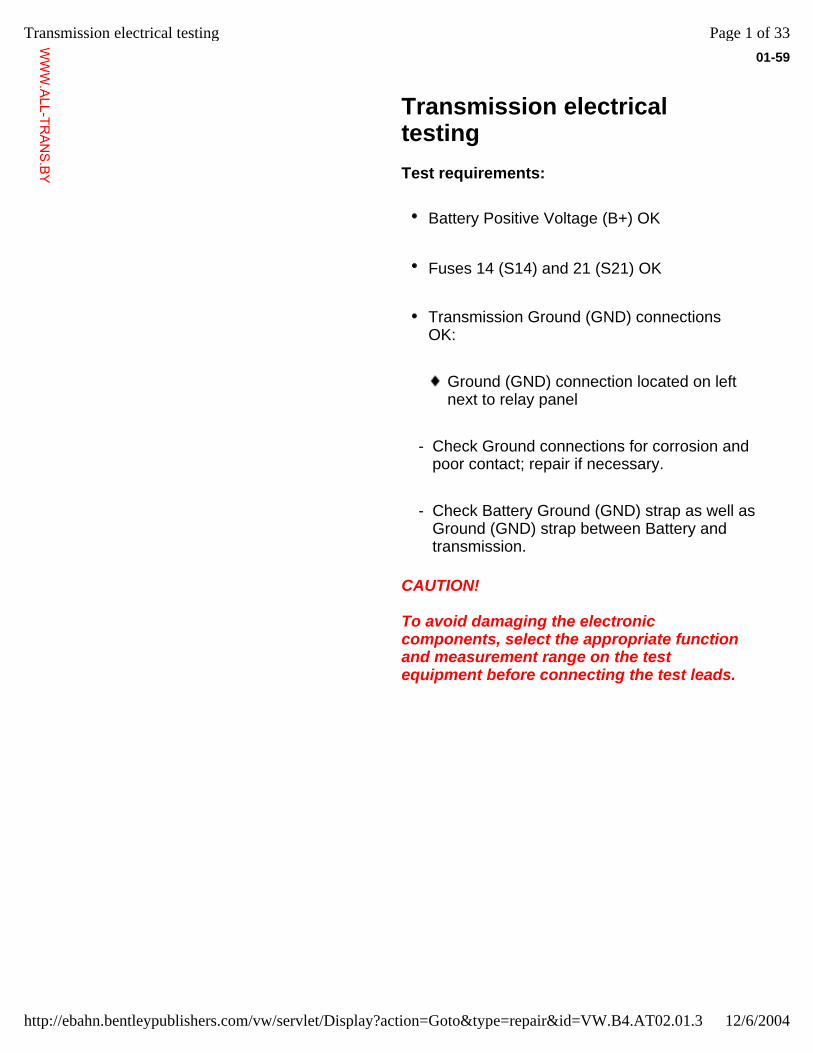
Transmission electrical testing
Test requirements:
Battery Positive Voltage (B+) OK
Fuses 14 (S14) and 21 (S21) OK
Transmission Ground (GND) connections OK:
Ground (GND) connection located on left next to relay panel
- Check Ground connections for corrosion and poor contact; repair if necessary.
- Check Battery Ground (GND) strap as well as Ground (GND) strap between Battery and transmission.
CAUTION!
To avoid damaging the electronic components, select the appropriate function and measurement range on the test equipment before connecting the test leads.
Page 1 of 33Transmission electrical testing
12/6/2004http://ebahn.bentleypublishers.com/vw/servlet/Display?action=Goto&type=repair&id=VW.B4.AT02.01.3
WWW.ALL-TR
ANS.BY
01-60
Note:
Use the hand multimeter (Fluke 83, VAG 1526 or equivalent)for testing.
Use auxiliary cables from the VAG 1594 adapter kit, and the test box as specified, for connecting test equipment.
The specified values are valid for ambient temperatures ranging from 0-40 C (32-104 F).
If the measured values differ from the specified values, determine the cause by using the wiring diagrams.
If the measured values differ only slightly from the specified values, clean the sockets and connectors of the test equipment and test leads, then repeat the test. Before replacing a particular component, test the wiring and connections and, particularly if specified values are below 10 ohms (10 ), repeat the resistance measurement.
Electrical testing on Transmission Control Module with 38-pin connector page 01-61
Electrical testing on Transmission Control Module with 68-pin connector page 01-73
Page 2 of 33Transmission electrical testing
12/6/2004http://ebahn.bentleypublishers.com/vw/servlet/Display?action=Goto&type=repair&id=VW.B4.AT02.01.3
WWW.ALL-TR
ANS.BY
01-61
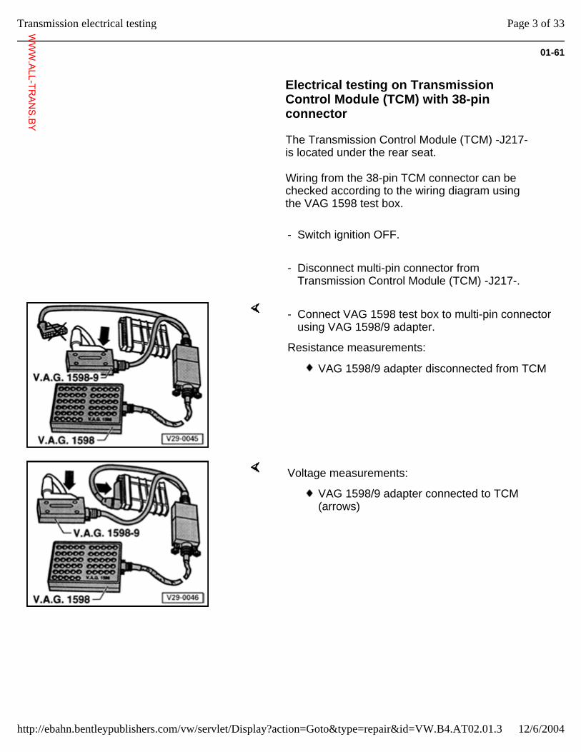
Electrical testing on Transmission Control Module (TCM) with 38-pin connector
The Transmission Control Module (TCM) -J217- is located under the rear seat.
Wiring from the 38-pin TCM connector can be checked according to the wiring diagram using the VAG 1598 test box.
- Switch ignition OFF.
- Disconnect multi-pin connector from Transmission Control Module (TCM) -J217-.
- Connect VAG 1598 test box to multi-pin connector using VAG 1598/9 adapter.
Resistance measurements:
VAG 1598/9 adapter disconnected from TCM
Voltage measurements:
VAG 1598/9 adapter connected to TCM (arrows)
Page 3 of 33Transmission electrical testing
12/6/2004http://ebahn.bentleypublishers.com/vw/servlet/Display?action=Goto&type=repair&id=VW.B4.AT02.01.3
WWW.ALL-TR
ANS.BY
01-62
Terminal assignment for 38-pin Transmission Control Module (TCM) -J217- connector(also sockets on VAG 1598 test box)
1- Ground (GND) (terminal 31) 20-
Shiftlock Solenoid -N110-
2- Solenoid Valve 4 -N91- 21-
Solenoid Valve 7 -N94-
3- Solenoid Valve 3 -N90- 22-
Solenoid Valve 1 -N88-
4- Not assigned 23-
Solenoid Valve 2 -N89-
5- Park/Nueltral signal 24-
Solenoid Valve 5 -N92-
6- On Board Diagnostic K-wire 25-
Solenoid Valve 6 -N93-
7- Not assigned 26-
Brake Light Switch -F- signal voltage
8- Kickdown for air conditioner 27-
Engine = TD-(RPM) signal
9- Throttle Position (TP) Sensor -G69- 28-
Engine = Ignition timing influence
10-
Throttle Position (TP) Sensor -G69-1) 29-
Throttle Position (TP) Sensor -G69- Ground (GND)1)
11-
Not assigned 30-
Transmission fluid (ATF) temperature
12-
Selector lever display -or- not assigned 31-
Not assigned
13-
Vehicle Speed Sensor (VSS) -G68- screening 32-
Vehicle Speed Sensor (VSS) -G68-
14-
Not assigned 33-
Vehicle Speed Sensor (VSS) -G68-
15-
Multi-Function Transmission Range (TR) Switch -F125-
34-
Multi-Function Transmission Range (TR) Switch -F125-
16-
Multi-Function Transmission Range (TR) Switch -F125
35-
Multi-Function Transmission Range (TR) Switch -F125
17-
Kick Down Switch -F8- 36-
Not assigned
18-
Battery Positive Voltage (B+) supply for Solenoid Valves
37-
Idle Switch
Page 4 of 33Transmission electrical testing
12/6/2004http://ebahn.bentleypublishers.com/vw/servlet/Display?action=Goto&type=repair&id=VW.B4.AT02.01.3
WWW.ALL-TR
ANS.BY
19-
Battery Positive Voltage (B+) (terminal 15) 38-
Cruise Control system
1) Voltage supply (contacts 10 and 29) not assigned on vehicles with 6-cylinder engine; Throttle Position (TP) Sensor signal (terminal 9) is routed to the Transmission Control Module (TCM) via the Motronic Engine Control Module (ECM).
Page 5 of 33Transmission electrical testing
12/6/2004http://ebahn.bentleypublishers.com/vw/servlet/Display?action=Goto&type=repair&id=VW.B4.AT02.01.3
WWW.ALL-TR
ANS.BY
01-63
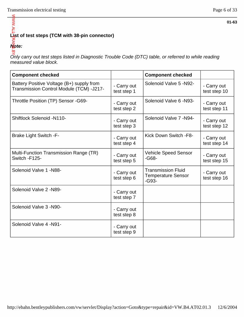
List of test steps (TCM with 38-pin connector)
Note:
Only carry out test steps listed in Diagnostic Trouble Code (DTC) table, or referred to while reading measured value block.
Component checked Component checked
Battery Positive Voltage (B+) supply from Transmission Control Module (TCM) -J217- - Carry out
test step 1 Solenoid Valve 5 -N92- - Carry out
test step 10
Throttle Position (TP) Sensor -G69- - Carry out test step 2
Solenoid Valve 6 -N93- - Carry out test step 11
Shiftlock Solenoid -N110- - Carry out test step 3
Solenoid Valve 7 -N94- - Carry out test step 12
Brake Light Switch -F- - Carry out test step 4
Kick Down Switch -F8- - Carry out test step 14
Multi-Function Transmission Range (TR) Switch -F125- - Carry out
test step 5 Vehicle Speed Sensor -G68- - Carry out
test step 15
Solenoid Valve 1 -N88- - Carry out test step 6
Transmission Fluid Temperature Sensor -G93-
- Carry out test step 16
Solenoid Valve 2 -N89- - Carry out test step 7
Solenoid Valve 3 -N90- - Carry out test step 8
Solenoid Valve 4 -N91- - Carry out test step 9
Page 6 of 33Transmission electrical testing
12/6/2004http://ebahn.bentleypublishers.com/vw/servlet/Display?action=Goto&type=repair&id=VW.B4.AT02.01.3
WWW.ALL-TR
ANS.BY
01-64
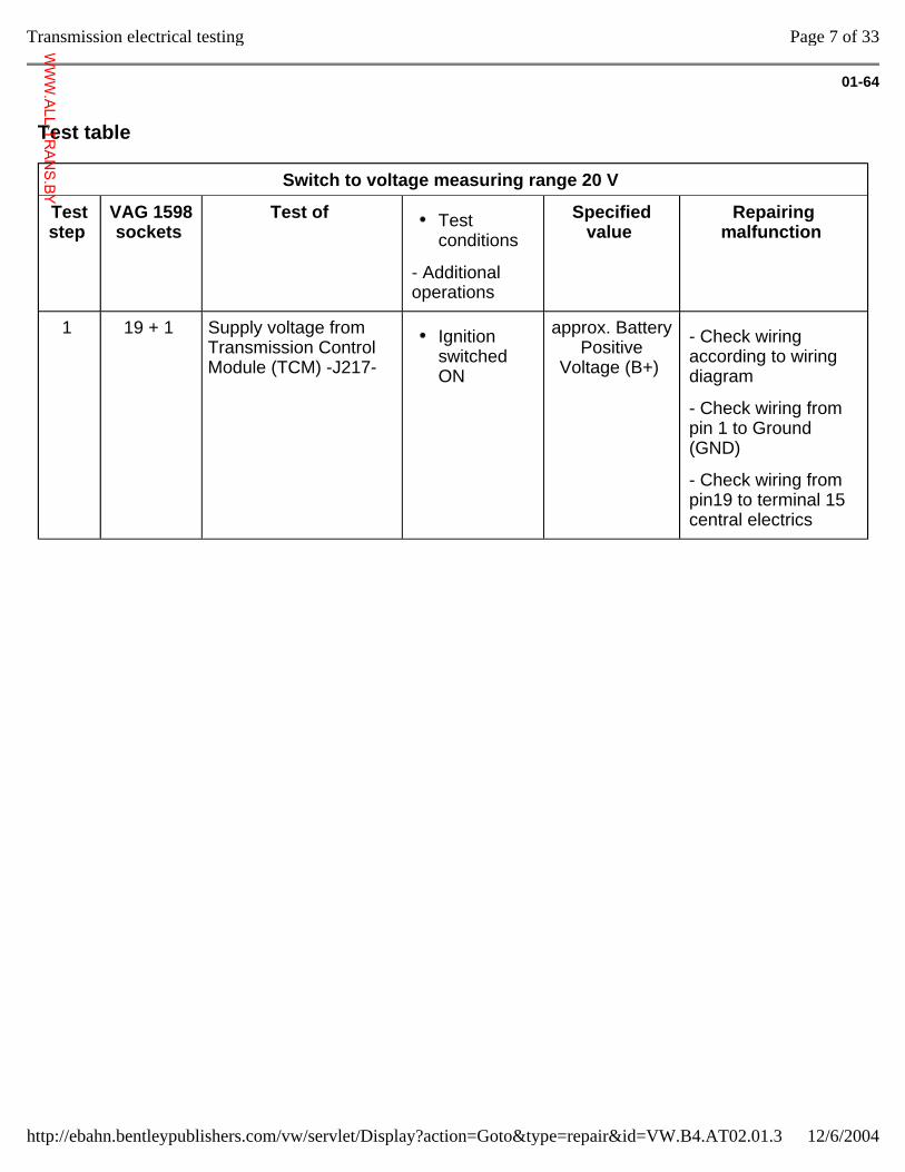
Test table
Switch to voltage measuring range 20 V
Test step
VAG 1598 sockets
Test of Test conditions
- Additional operations
Specified value
Repairing malfunction
1 19 + 1 Supply voltage from Transmission Control Module (TCM) -J217-
Ignition switched ON
approx. Battery Positive
Voltage (B+)
- Check wiring according to wiring diagram
- Check wiring from pin 1 to Ground (GND)
- Check wiring from pin19 to terminal 15 central electrics
Page 7 of 33Transmission electrical testing
12/6/2004http://ebahn.bentleypublishers.com/vw/servlet/Display?action=Goto&type=repair&id=VW.B4.AT02.01.3
WWW.ALL-TR
ANS.BY
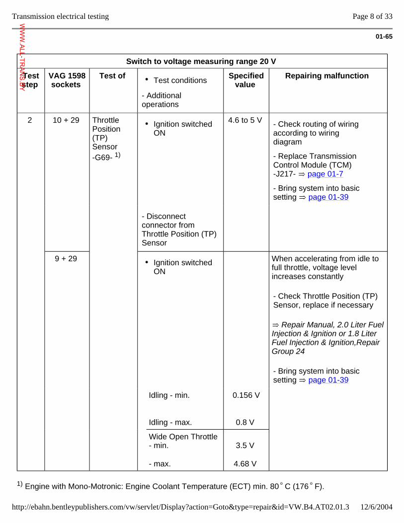
01-65
Switch to voltage measuring range 20 V
Test step
VAG 1598 sockets
Test of Test conditions
- Additional operations
Specified value
Repairing malfunction
2 10 + 29 Throttle Position (TP) Sensor -G69- 1)
Ignition switched ON
4.6 to 5 V - Check routing of wiring according to wiring diagram
- Replace Transmission Control Module (TCM) -J217- page 01-7
- Bring system into basic setting page 01-39
- Disconnect connector from Throttle Position (TP) Sensor
9 + 29 Ignition switched ON
When accelerating from idle to full throttle, voltage level increases constantly
Repair Manual, 2.0 Liter Fuel Injection & Ignition or 1.8 Liter Fuel Injection & Ignition,Repair Group 24
- Check Throttle Position (TP) Sensor, replace if necessary
- Bring system into basic setting page 01-39
Idling - min.
Idling - max.
0.156 V
0.8 V
Wide Open Throttle - min.
- max.
3.5 V
4.68 V
1) Engine with Mono-Motronic: Engine Coolant Temperature (ECT) min. 80 C (176 F).
Page 8 of 33Transmission electrical testing
12/6/2004http://ebahn.bentleypublishers.com/vw/servlet/Display?action=Goto&type=repair&id=VW.B4.AT02.01.3
WWW.ALL-TR
ANS.BY
Not checked on vehicles with 6-cylinder engine; Signal from TP Sensor -G69- is directed to TCM via ECM and can only be measured by the "Reading measured value block" function using the VAG 1551 Scan Tool page 01-40
Page 9 of 33Transmission electrical testing
12/6/2004http://ebahn.bentleypublishers.com/vw/servlet/Display?action=Goto&type=repair&id=VW.B4.AT02.01.3
WWW.ALL-TR
ANS.BY
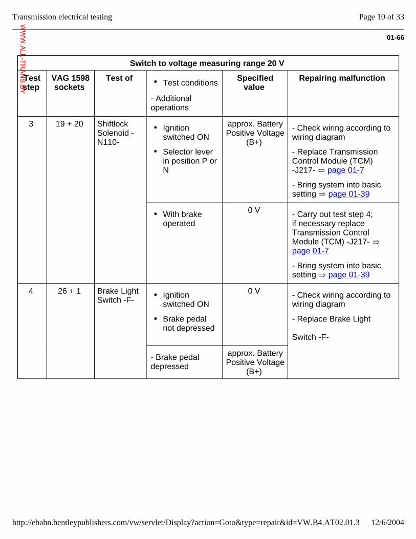
01-66
Switch to voltage measuring range 20 V
Test step
VAG 1598 sockets
Test of Test conditions
- Additional operations
Specified value
Repairing malfunction
3 19 + 20 Shiftlock Solenoid -N110-
Ignition switched ON
Selector lever in position P or N
approx. Battery Positive Voltage
(B+)
- Check wiring according to wiring diagram
- Replace Transmission Control Module (TCM) -J217- page 01-7
- Bring system into basic setting page 01-39
With brake operated
0 V - Carry out test step 4; if necessary replace Transmission Control Module (TCM) -J217- page 01-7
- Bring system into basic setting page 01-39
4 26 + 1 Brake Light Switch -F- Ignition
switched ON
Brake pedal not depressed
0 V - Check wiring according to wiring diagram
- Replace Brake Light Switch -F-
- Brake pedal depressed
approx. Battery Positive Voltage
(B+)
Page 10 of 33Transmission electrical testing
12/6/2004http://ebahn.bentleypublishers.com/vw/servlet/Display?action=Goto&type=repair&id=VW.B4.AT02.01.3
WWW.ALL-TR
ANS.BY
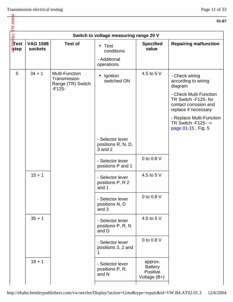
01-67
Switch to voltage measuring range 20 V
Test step
VAG 1598 sockets
Test of Test conditions
- Additional operations
Specified value
Repairing malfunction
5 34 + 1 Multi-Function Transmission Range (TR) Switch -F125-
Ignition switched ON
4.5 to 5 V - Check wiring according to wiring diagram
- Check Multi-Function TR Switch -F125- for contact corrosion and replace if necessary
- Replace Multi-Function TR Switch -F125- page 01-15 , Fig. 5
- Selector lever positions R, N, D, 3 and 2
- Selector lever positions P and 1
0 to 0.8 V
15 + 1 - Selector lever positions P, R 2 and 1
4.5 to 5 V
- Selector lever positions N, D and 3
0 to 0.8 V
35 + 1 - Selector lever positions P, R, N and D
4.5 to 5 V
- Selector lever positions 3, 2 and 1
0 to 0.8 V
16 + 1 - Selector lever positions P, R, and N
approx. Battery Positive
Voltage (B+)
Page 11 of 33Transmission electrical testing
12/6/2004http://ebahn.bentleypublishers.com/vw/servlet/Display?action=Goto&type=repair&id=VW.B4.AT02.01.3
WWW.ALL-TR
ANS.BY
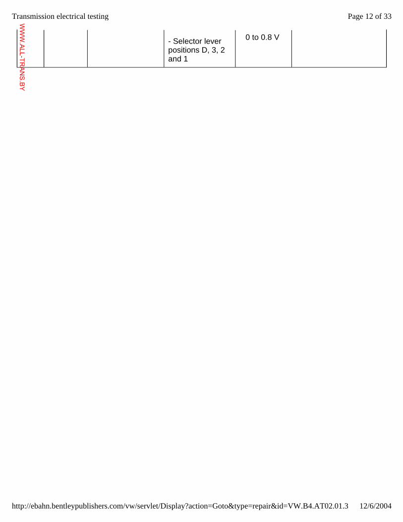
- Selector lever positions D, 3, 2 and 1
0 to 0.8 V
Page 12 of 33Transmission electrical testing
12/6/2004http://ebahn.bentleypublishers.com/vw/servlet/Display?action=Goto&type=repair&id=VW.B4.AT02.01.3
WWW.ALL-TR
ANS.BY
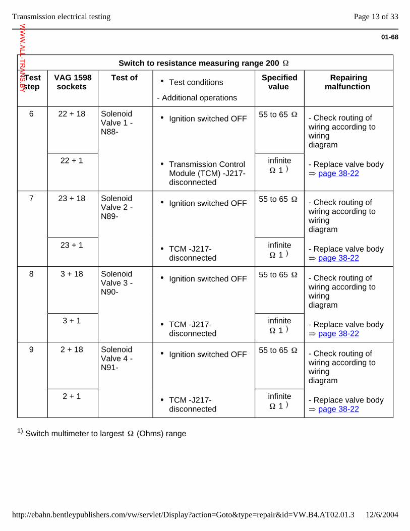
01-68
Switch to resistance measuring range 200
Test step
VAG 1598 sockets
Test of Test conditions
- Additional operations
Specified value
Repairing malfunction
6 22 + 18 Solenoid Valve 1 -N88-
Ignition switched OFF 55 to 65 - Check routing of wiring according to wiring diagram
22 + 1 Transmission Control Module (TCM) -J217- disconnected
infinite 1
- Replace valve body page 38-22
7 23 + 18 Solenoid Valve 2 -N89-
Ignition switched OFF 55 to 65 - Check routing of wiring according to wiring diagram
23 + 1 TCM -J217- disconnected
infinite 1
- Replace valve body page 38-22
8 3 + 18 Solenoid Valve 3 -N90-
Ignition switched OFF 55 to 65 - Check routing of wiring according to wiring diagram
3 + 1 TCM -J217- disconnected
infinite 1
- Replace valve body page 38-22
9 2 + 18 Solenoid Valve 4 -N91-
Ignition switched OFF 55 to 65 - Check routing of wiring according to wiring diagram
2 + 1 TCM -J217- disconnected
infinite 1
- Replace valve body page 38-22
1) Switch multimeter to largest (Ohms) range
Page 13 of 33Transmission electrical testing
12/6/2004http://ebahn.bentleypublishers.com/vw/servlet/Display?action=Goto&type=repair&id=VW.B4.AT02.01.3
WWW.ALL-TR
ANS.BY
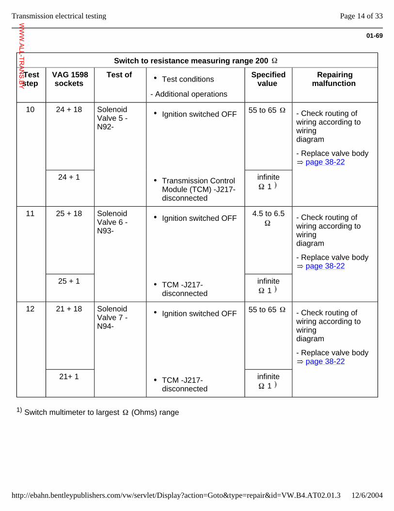
01-69
Switch to resistance measuring range 200
Test step
VAG 1598 sockets
Test of Test conditions
- Additional operations
Specified value
Repairing malfunction
10 24 + 18 Solenoid Valve 5 -N92-
Ignition switched OFF 55 to 65 - Check routing of wiring according to wiring diagram
- Replace valve body page 38-22
24 + 1 Transmission Control Module (TCM) -J217- disconnected
infinite 1
11 25 + 18 Solenoid Valve 6 -N93-
Ignition switched OFF 4.5 to 6.5
- Check routing of wiring according to wiring diagram
- Replace valve body page 38-22
25 + 1 TCM -J217- disconnected
infinite 1
12 21 + 18 Solenoid Valve 7 -N94-
Ignition switched OFF 55 to 65 - Check routing of wiring according to wiring diagram
- Replace valve body page 38-22
21+ 1 TCM -J217- disconnected
infinite 1
1) Switch multimeter to largest (Ohms) range
Page 14 of 33Transmission electrical testing
12/6/2004http://ebahn.bentleypublishers.com/vw/servlet/Display?action=Goto&type=repair&id=VW.B4.AT02.01.3
WWW.ALL-TR
ANS.BY
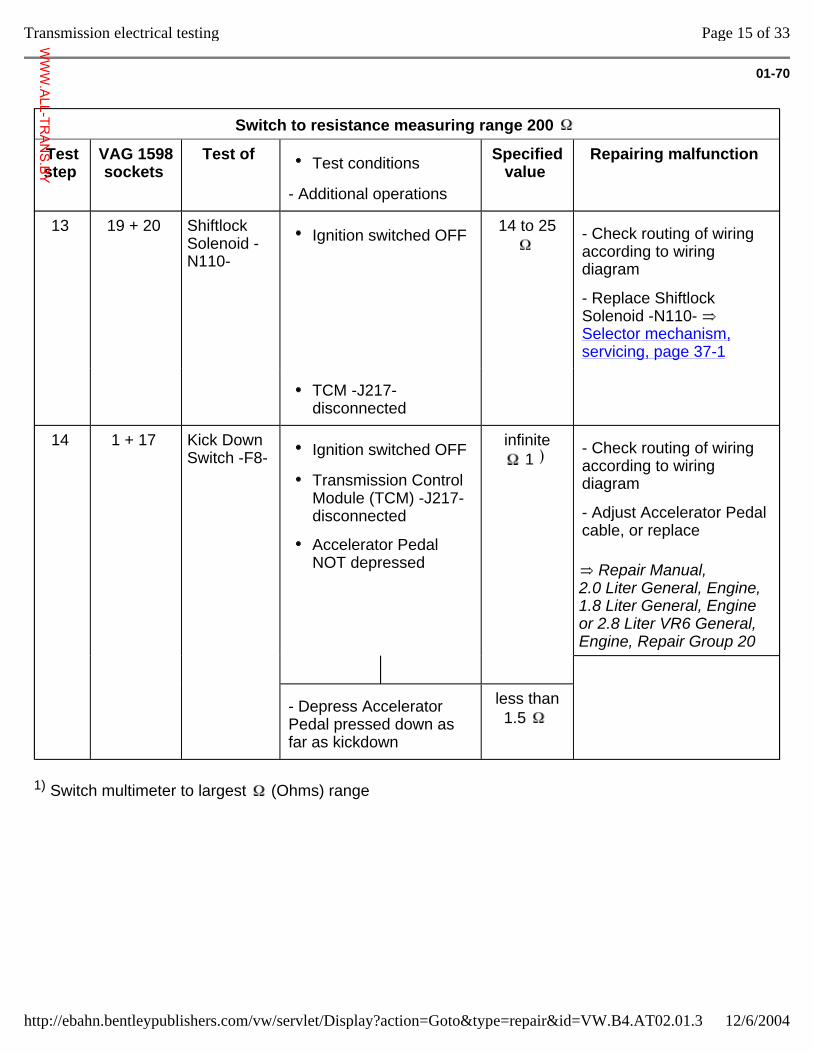
01-70
Switch to resistance measuring range 200
Test step
VAG 1598 sockets
Test of Test conditions
- Additional operations
Specified value
Repairing malfunction
13 19 + 20 Shiftlock Solenoid -N110-
Ignition switched OFF 14 to 25
- Check routing of wiring according to wiring diagram
- Replace Shiftlock Solenoid -N110- Selector mechanism, servicing, page 37-1
TCM -J217- disconnected
14 1 + 17 Kick Down Switch -F8- Ignition switched OFF
Transmission Control Module (TCM) -J217- disconnected
Accelerator Pedal NOT depressed
infinite 1
Repair Manual, 2.0 Liter General, Engine, 1.8 Liter General, Engine or 2.8 Liter VR6 General, Engine, Repair Group 20
- Check routing of wiring according to wiring diagram
- Adjust Accelerator Pedal cable, or replace
- Depress Accelerator Pedal pressed down as far as kickdown
less than 1.5
1) Switch multimeter to largest (Ohms) range
Page 15 of 33Transmission electrical testing
12/6/2004http://ebahn.bentleypublishers.com/vw/servlet/Display?action=Goto&type=repair&id=VW.B4.AT02.01.3
WWW.ALL-TR
ANS.BY
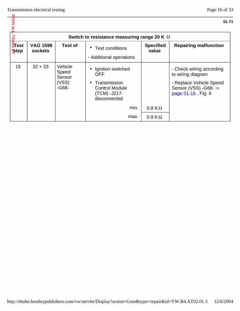
01-71
Switch to resistance measuring range 20 K
Test step
VAG 1598 sockets
Test of Test conditions
- Additional operations
Specified value
Repairing malfunction
15 32 + 33 Vehicle Speed Sensor (VSS) -G68-
Ignition switched OFF
Transmission Control Module (TCM) -J217- disconnected
- Check wiring according to wiring diagram
- Replace Vehicle Speed Sensor (VSS) -G68- page 01-16 , Fig. 6
min. 0.8 K
max. 0.9 K
Page 16 of 33Transmission electrical testing
12/6/2004http://ebahn.bentleypublishers.com/vw/servlet/Display?action=Goto&type=repair&id=VW.B4.AT02.01.3
WWW.ALL-TR
ANS.BY
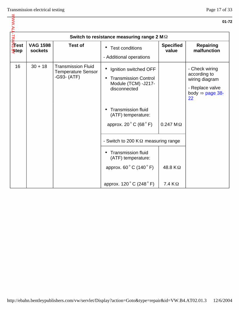
01-72
Switch to resistance measuring range 2 M
Test step
VAG 1598 sockets
Test of Test conditions
- Additional operations
Specified value
Repairing malfunction
16 30 + 18 Transmission Fluid Temperature Sensor -G93- (ATF)
Ignition switched OFF
Transmission Control Module (TCM) -J217- disconnected
- Check wiring according to wiring diagram
- Replace valve body page 38-22
Transmission fluid (ATF) temperature:
approx. 20 C (68 F)
0.247 M
- Switch to 200 K measuring range
Transmission fluid (ATF) temperature:
approx. 60 C (140 F)
approx. 120 C (248 F)
48.8 K
7.4 K
Page 17 of 33Transmission electrical testing
12/6/2004http://ebahn.bentleypublishers.com/vw/servlet/Display?action=Goto&type=repair&id=VW.B4.AT02.01.3
WWW.ALL-TR
ANS.BY
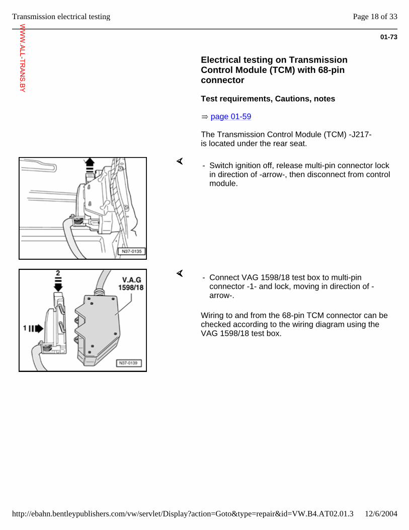
01-73
Electrical testing on Transmission Control Module (TCM) with 68-pin connector
Test requirements, Cautions, notes
page 01-59
The Transmission Control Module (TCM) -J217- is located under the rear seat.
- Switch ignition off, release multi-pin connector lock in direction of -arrow-, then disconnect from control module.
Wiring to and from the 68-pin TCM connector can be checked according to the wiring diagram using the VAG 1598/18 test box.
- Connect VAG 1598/18 test box to multi-pin connector -1- and lock, moving in direction of -arrow-.
Page 18 of 33Transmission electrical testing
12/6/2004http://ebahn.bentleypublishers.com/vw/servlet/Display?action=Goto&type=repair&id=VW.B4.AT02.01.3
WWW.ALL-TR
ANS.BY
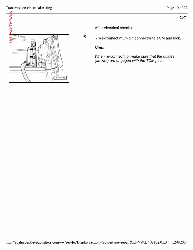
01-74
After electrical checks:
Note:
When re-connecting, make sure that the guides (arrows) are engaged with the TCM pins.
- Re-connect multi-pin connector to TCM and lock.
Page 19 of 33Transmission electrical testing
12/6/2004http://ebahn.bentleypublishers.com/vw/servlet/Display?action=Goto&type=repair&id=VW.B4.AT02.01.3
WWW.ALL-TR
ANS.BY
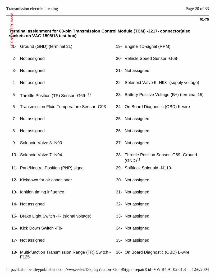
01-75
Terminal assignment for 68-pin Transmission Control Module (TCM) -J217- connector(also sockets on VAG 1598/18 test box)
1- Ground (GND) (terminal 31) 19-
Engine TD-signal (RPM)
2- Not assigned 20-
Vehicle Speed Sensor -G68-
3- Not assigned 21-
Not assigned
4- Not assigned 22-
Solenoid Valve 6 -N93- (supply voltage)
5- Throttle Position (TP) Sensor -G69- 1) 23-
Battery Positive Voltage (B+) (terminal 15)
6- Transmission Fluid Temperature Sensor -G93- 24-
On Board Diagnostic (OBD) K-wire
7- Not assigned 25-
Not assigned
8- Not assigned 26-
Not assigned
9- Solenoid Valve 3 -N90- 27-
Not assigned
10-
Solenoid Valve 7 -N94- 28-
Throttle Position Sensor -G69- Ground (GND)1)
11-
Park/Neutral Position (PNP) signal 29-
Shiftlock Solenoid -N110-
12-
Kickdown for air conditioner 30-
Not assigned
13-
Ignition timing influence 31-
Not assigned
14-
Not assigned 32-
Not assigned
15-
Brake Light Switch -F- (signal voltage) 33-
Not assigned
16-
Kick Down Switch -F8- 34-
Not assigned
17-
Not assigned 35-
Not assigned
18-
Multi-function Transmission Range (TR) Switch -F125-
36-
On Board Diagnostic (OBD) L-wire
Page 20 of 33Transmission electrical testing
12/6/2004http://ebahn.bentleypublishers.com/vw/servlet/Display?action=Goto&type=repair&id=VW.B4.AT02.01.3
WWW.ALL-TR
ANS.BY
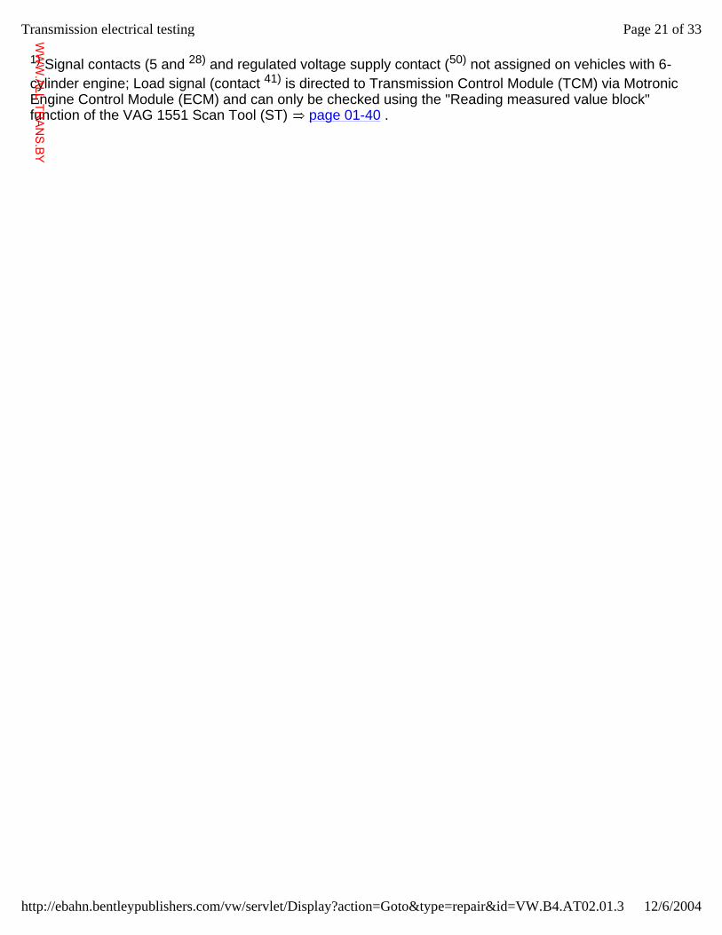
1) Signal contacts (5 and 28) and regulated voltage supply contact (50) not assigned on vehicles with 6-cylinder engine; Load signal (contact 41) is directed to Transmission Control Module (TCM) via Motronic Engine Control Module (ECM) and can only be checked using the "Reading measured value block" function of the VAG 1551 Scan Tool (ST) page 01-40 .
Page 21 of 33Transmission electrical testing
12/6/2004http://ebahn.bentleypublishers.com/vw/servlet/Display?action=Goto&type=repair&id=VW.B4.AT02.01.3
WWW.ALL-TR
ANS.BY
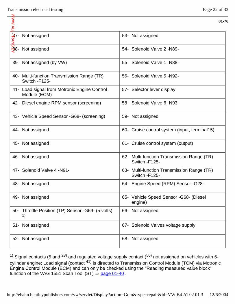
01-76
37-
Not assigned 53-
Not assigned
38-
Not assigned 54-
Solenoid Valve 2 -N89-
39-
Not assigned (by VW) 55-
Solenoid Valve 1 -N88-
40-
Multi-function Transmission Range (TR) Switch -F125-
56-
Solenoid Valve 5 -N92-
41-
Load signal from Motronic Engine Control Module (ECM)
57-
Selector lever display
42-
Diesel engine RPM sensor (screening) 58-
Solenoid Valve 6 -N93-
43-
Vehicle Speed Sensor -G68- (screening) 59-
Not assigned
44-
Not assigned 60-
Cruise control system (input, terminal15)
45-
Not assigned 61-
Cruise control system (output)
46-
Not assigned 62-
Multi-function Transmission Range (TR) Switch -F125-
47-
Solenoid Valve 4 -N91- 63-
Multi-function Transmission Range (TR) Switch -F125-
48-
Not assigned 64-
Engine Speed (RPM) Sensor -G28-
49-
Not assigned 65-
Vehicle Speed Sensor -G68- (Diesel engine)
50-
Throttle Position (TP) Sensor -G69- (5 volts) 1)
66-
Not assigned
51-
Not assigned 67-
Solenoid Valves voltage supply
52-
Not assigned 68-
Not assigned
1) Signal contacts (5 and 28) and regulated voltage supply contact (50) not assigned on vehicles with 6-cylinder engine; Load signal (contact 41) is directed to Transmission Control Module (TCM) via Motronic Engine Control Module (ECM) and can only be checked using the "Reading measured value block" function of the VAG 1551 Scan Tool (ST) page 01-40 .
Page 22 of 33Transmission electrical testing
12/6/2004http://ebahn.bentleypublishers.com/vw/servlet/Display?action=Goto&type=repair&id=VW.B4.AT02.01.3
WWW.ALL-TR
ANS.BY
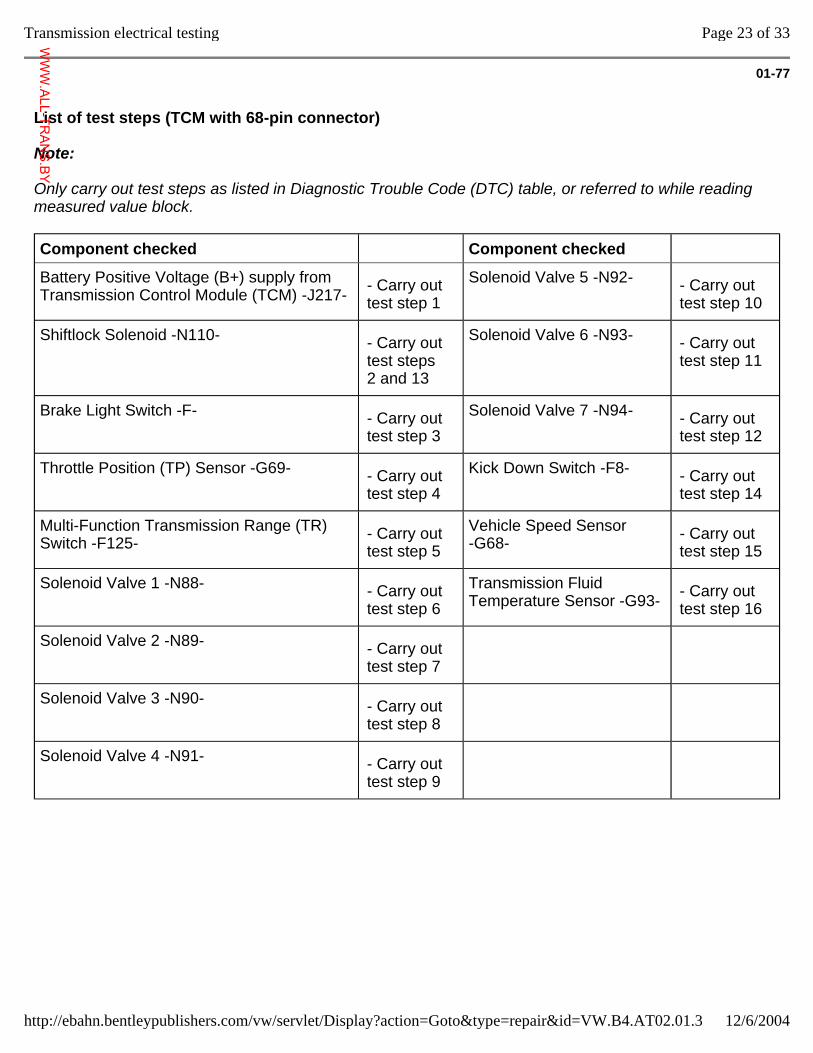
01-77
List of test steps (TCM with 68-pin connector)
Note:
Only carry out test steps as listed in Diagnostic Trouble Code (DTC) table, or referred to while reading measured value block.
Component checked Component checked
Battery Positive Voltage (B+) supply from Transmission Control Module (TCM) -J217- - Carry out
test step 1 Solenoid Valve 5 -N92- - Carry out
test step 10
Shiftlock Solenoid -N110- - Carry out test steps 2 and 13
Solenoid Valve 6 -N93- - Carry out test step 11
Brake Light Switch -F- - Carry out test step 3
Solenoid Valve 7 -N94- - Carry out test step 12
Throttle Position (TP) Sensor -G69- - Carry out test step 4
Kick Down Switch -F8- - Carry out test step 14
Multi-Function Transmission Range (TR) Switch -F125- - Carry out
test step 5 Vehicle Speed Sensor -G68- - Carry out
test step 15
Solenoid Valve 1 -N88- - Carry out test step 6
Transmission Fluid Temperature Sensor -G93- - Carry out
test step 16
Solenoid Valve 2 -N89- - Carry out test step 7
Solenoid Valve 3 -N90- - Carry out test step 8
Solenoid Valve 4 -N91- - Carry out test step 9
Page 23 of 33Transmission electrical testing
12/6/2004http://ebahn.bentleypublishers.com/vw/servlet/Display?action=Goto&type=repair&id=VW.B4.AT02.01.3
WWW.ALL-TR
ANS.BY
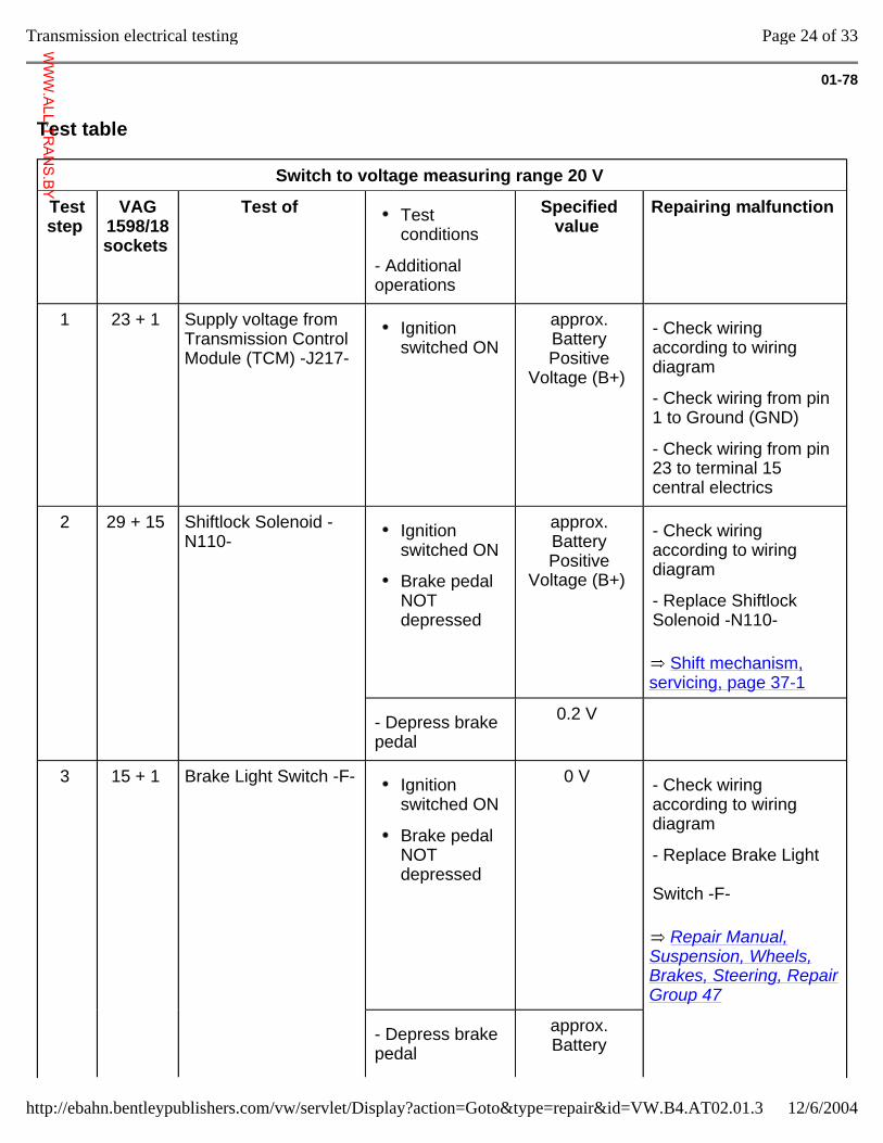
01-78
Test table
Switch to voltage measuring range 20 V
Test step
VAG 1598/18 sockets
Test of Test conditions
- Additional operations
Specified value
Repairing malfunction
1 23 + 1 Supply voltage from Transmission Control Module (TCM) -J217-
Ignition switched ON
approx. Battery Positive
Voltage (B+)
- Check wiring according to wiring diagram
- Check wiring from pin 1 to Ground (GND)
- Check wiring from pin 23 to terminal 15 central electrics
2 29 + 15 Shiftlock Solenoid -N110- Ignition
switched ON
Brake pedal NOT depressed
approx. Battery Positive
Voltage (B+)
Shift mechanism, servicing, page 37-1
- Check wiring according to wiring diagram
- Replace Shiftlock Solenoid -N110-
- Depress brake pedal
0.2 V
3 15 + 1 Brake Light Switch -F- Ignition
switched ON
Brake pedal NOT depressed
0 V
Repair Manual, Suspension, Wheels, Brakes, Steering, Repair Group 47
- Check wiring according to wiring diagram
- Replace Brake Light Switch -F-
- Depress brake pedal
approx. Battery
Page 24 of 33Transmission electrical testing
12/6/2004http://ebahn.bentleypublishers.com/vw/servlet/Display?action=Goto&type=repair&id=VW.B4.AT02.01.3
WWW.ALL-TR
ANS.BY
Positive Voltage (B+)
Page 25 of 33Transmission electrical testing
12/6/2004http://ebahn.bentleypublishers.com/vw/servlet/Display?action=Goto&type=repair&id=VW.B4.AT02.01.3
WWW.ALL-TR
ANS.BY
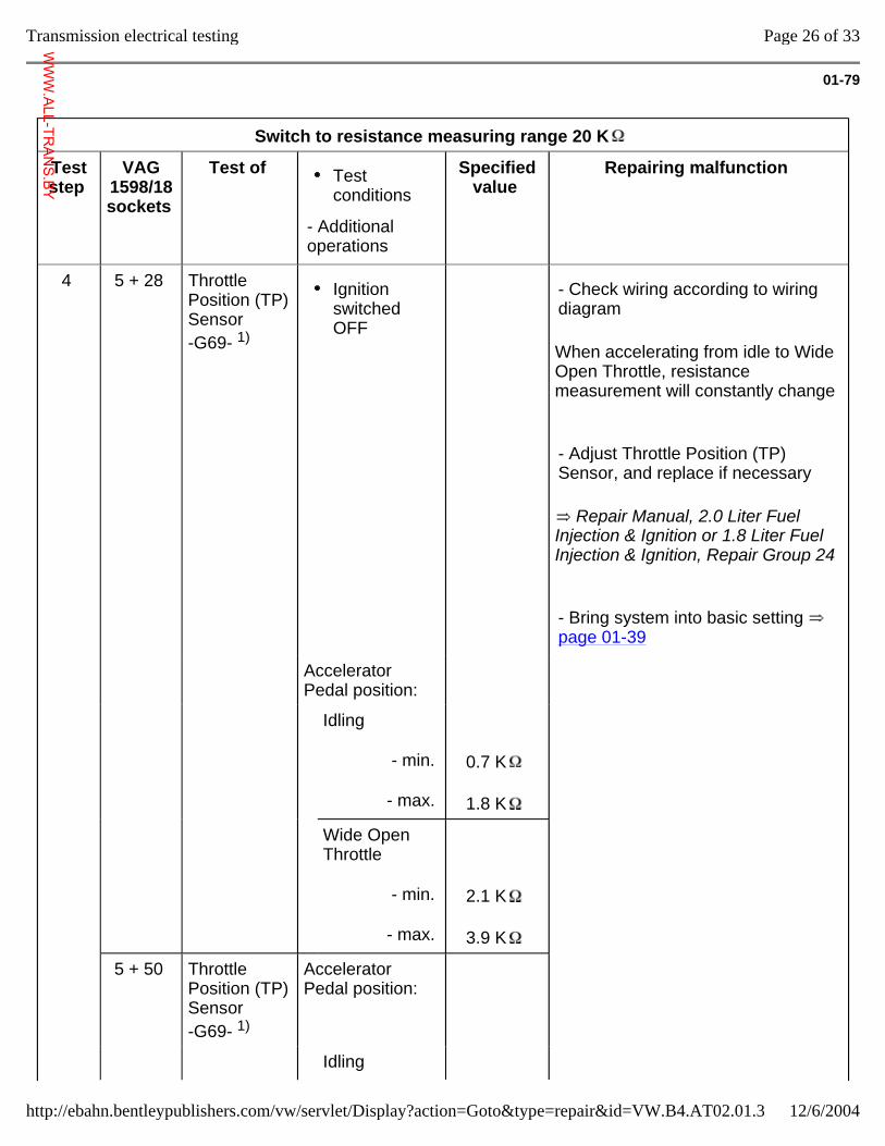
01-79
Switch to resistance measuring range 20 K
Test step
VAG 1598/18 sockets
Test of Test conditions
- Additional operations
Specified value
Repairing malfunction
4 5 + 28 Throttle Position (TP) Sensor -G69- 1)
Ignition switched OFF
When accelerating from idle to Wide Open Throttle, resistance measurement will constantly change
Repair Manual, 2.0 Liter Fuel Injection & Ignition or 1.8 Liter Fuel Injection & Ignition, Repair Group 24
- Check wiring according to wiring diagram
- Adjust Throttle Position (TP) Sensor, and replace if necessary
- Bring system into basic setting page 01-39
Accelerator Pedal position:
Idling
- min.
- max.
0.7 K
1.8 K
Wide Open Throttle
- min.
- max.
2.1 K
3.9 K
5 + 50 Throttle Position (TP) Sensor -G69- 1)
Accelerator Pedal position:
Idling
Page 26 of 33Transmission electrical testing
12/6/2004http://ebahn.bentleypublishers.com/vw/servlet/Display?action=Goto&type=repair&id=VW.B4.AT02.01.3
WWW.ALL-TR
ANS.BY
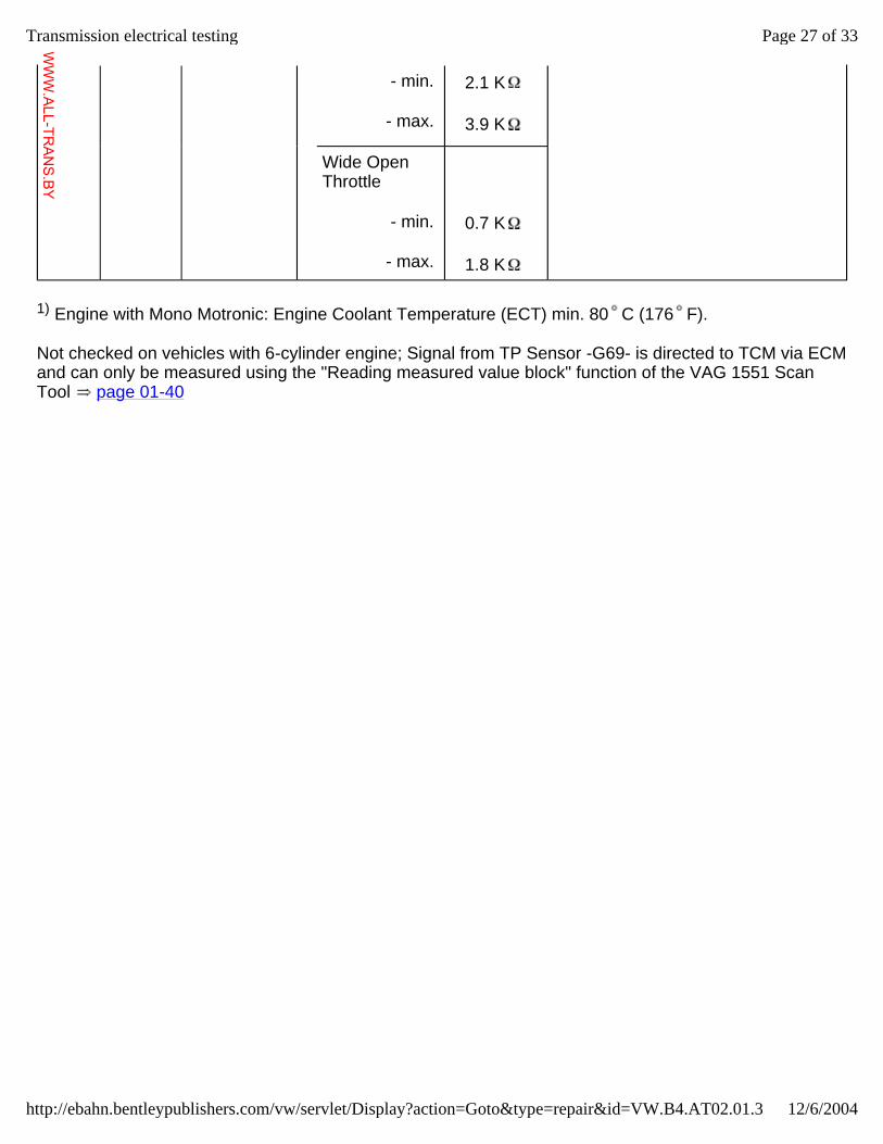
- min.
- max.
2.1 K
3.9 K
Wide Open Throttle
- min.
- max.
0.7 K
1.8 K
1) Engine with Mono Motronic: Engine Coolant Temperature (ECT) min. 80 C (176 F).
Not checked on vehicles with 6-cylinder engine; Signal from TP Sensor -G69- is directed to TCM via ECM and can only be measured using the "Reading measured value block" function of the VAG 1551 Scan Tool page 01-40
Page 27 of 33Transmission electrical testing
12/6/2004http://ebahn.bentleypublishers.com/vw/servlet/Display?action=Goto&type=repair&id=VW.B4.AT02.01.3
WWW.ALL-TR
ANS.BY
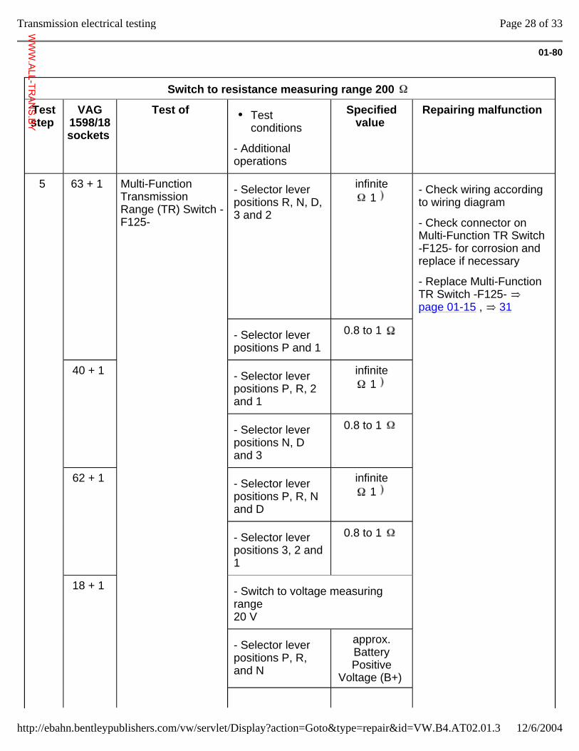
01-80
Switch to resistance measuring range 200
Test step
VAG 1598/18 sockets
Test of Test conditions
- Additional operations
Specified value
Repairing malfunction
5 63 + 1 Multi-Function Transmission Range (TR) Switch -F125-
- Selector lever positions R, N, D, 3 and 2
infinite 1
- Check wiring according to wiring diagram
- Check connector on Multi-Function TR Switch -F125- for corrosion and replace if necessary
- Replace Multi-Function TR Switch -F125- page 01-15 , 31
- Selector lever positions P and 1
0.8 to 1
40 + 1 - Selector lever positions P, R, 2 and 1
infinite 1
- Selector lever positions N, D and 3
0.8 to 1
62 + 1 - Selector lever positions P, R, N and D
infinite 1
- Selector lever positions 3, 2 and 1
0.8 to 1
18 + 1 - Switch to voltage measuring range 20 V
- Selector lever positions P, R, and N
approx. Battery Positive
Voltage (B+)
Page 28 of 33Transmission electrical testing
12/6/2004http://ebahn.bentleypublishers.com/vw/servlet/Display?action=Goto&type=repair&id=VW.B4.AT02.01.3
WWW.ALL-TR
ANS.BY
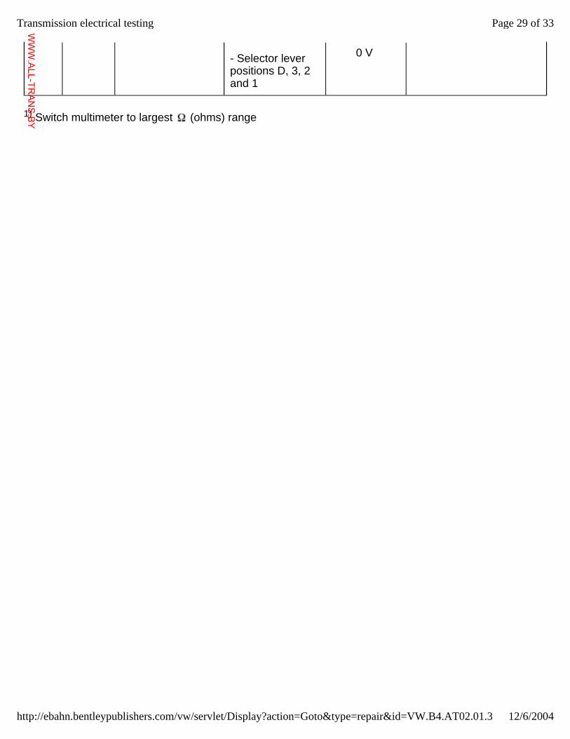
- Selector lever positions D, 3, 2 and 1
0 V
1) Switch multimeter to largest (ohms) range
Page 29 of 33Transmission electrical testing
12/6/2004http://ebahn.bentleypublishers.com/vw/servlet/Display?action=Goto&type=repair&id=VW.B4.AT02.01.3
WWW.ALL-TR
ANS.BY
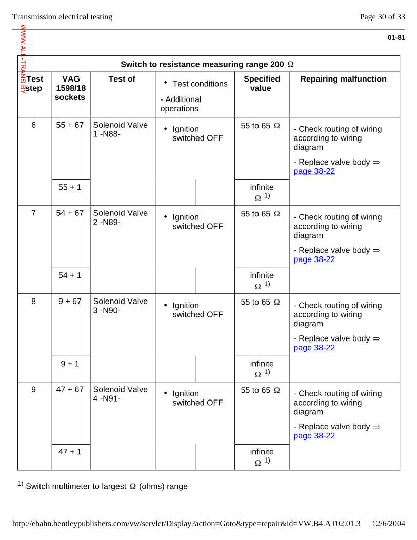
01-81
Switch to resistance measuring range 200
Test step
VAG 1598/18 sockets
Test of Test conditions
- Additional operations
Specified value
Repairing malfunction
6 55 + 67 Solenoid Valve 1 -N88- Ignition
switched OFF 55 to 65 - Check routing of wiring
according to wiring diagram
- Replace valve body page 38-22
55 + 1 infinite 1)
7 54 + 67 Solenoid Valve 2 -N89- Ignition
switched OFF 55 to 65 - Check routing of wiring
according to wiring diagram
- Replace valve body page 38-22
54 + 1 infinite 1)
8 9 + 67 Solenoid Valve 3 -N90- Ignition
switched OFF 55 to 65 - Check routing of wiring
according to wiring diagram
- Replace valve body page 38-22
9 + 1 infinite 1)
9 47 + 67 Solenoid Valve 4 -N91- Ignition
switched OFF 55 to 65 - Check routing of wiring
according to wiring diagram
- Replace valve body page 38-22
47 + 1 infinite 1)
1) Switch multimeter to largest (ohms) range
Page 30 of 33Transmission electrical testing
12/6/2004http://ebahn.bentleypublishers.com/vw/servlet/Display?action=Goto&type=repair&id=VW.B4.AT02.01.3
WWW.ALL-TR
ANS.BY
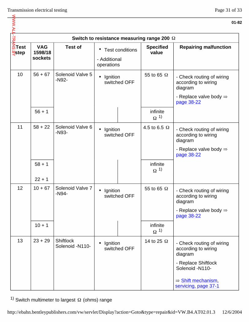
01-82
Switch to resistance measuring range 200
Test step
VAG 1598/18 sockets
Test of Test conditions
- Additional operations
Specified value
Repairing malfunction
10 56 + 67 Solenoid Valve 5 -N92- Ignition
switched OFF 55 to 65 - Check routing of wiring
according to wiring diagram
- Replace valve body page 38-22
56 + 1 infinite 1)
11 58 + 22 Solenoid Valve 6 -N93- Ignition
switched OFF 4.5 to 6.5 - Check routing of wiring
according to wiring diagram
- Replace valve body page 38-22
58 + 1 infinite 1)
22 + 1
12 10 + 67 Solenoid Valve 7 -N94- Ignition
switched OFF 55 to 65 - Check routing of wiring
according to wiring diagram
- Replace valve body page 38-22
10 + 1 infinite 1)
13 23 + 29 Shiftlock Solenoid -N110- Ignition
switched OFF 14 to 25
Shift mechanism, servicing, page 37-1
- Check routing of wiring according to wiring diagram
- Replace Shiftlock Solenoid -N110-
1) Switch multimeter to largest (ohms) range
Page 31 of 33Transmission electrical testing
12/6/2004http://ebahn.bentleypublishers.com/vw/servlet/Display?action=Goto&type=repair&id=VW.B4.AT02.01.3
WWW.ALL-TR
ANS.BY
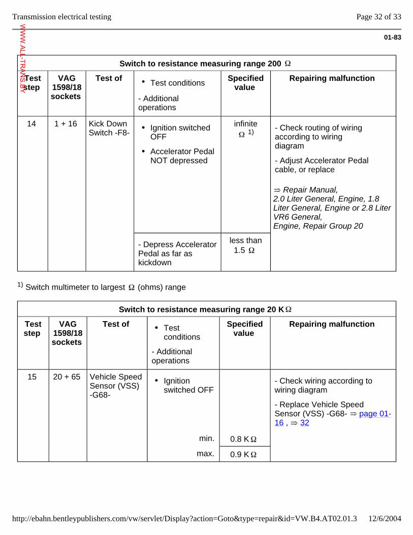
01-83
Switch to resistance measuring range 200
Test step
VAG 1598/18 sockets
Test of Test conditions
- Additional operations
Specified value
Repairing malfunction
14 1 + 16 Kick Down Switch -F8-
Ignition switched OFF
Accelerator Pedal NOT depressed
infinite 1)
Repair Manual, 2.0 Liter General, Engine, 1.8 Liter General, Engine or 2.8 Liter VR6 General, Engine, Repair Group 20
- Check routing of wiring according to wiring diagram
- Adjust Accelerator Pedal cable, or replace
- Depress Accelerator Pedal as far as kickdown
less than 1.5
1) Switch multimeter to largest (ohms) range
Switch to resistance measuring range 20 K
Test step
VAG 1598/18 sockets
Test of Test conditions
- Additional operations
Specified value
Repairing malfunction
15 20 + 65 Vehicle Speed Sensor (VSS) -G68-
Ignition switched OFF
- Check wiring according to wiring diagram
- Replace Vehicle Speed Sensor (VSS) -G68- page 01-16 , 32
min. 0.8 K
max. 0.9 K
Page 32 of 33Transmission electrical testing
12/6/2004http://ebahn.bentleypublishers.com/vw/servlet/Display?action=Goto&type=repair&id=VW.B4.AT02.01.3
WWW.ALL-TR
ANS.BY
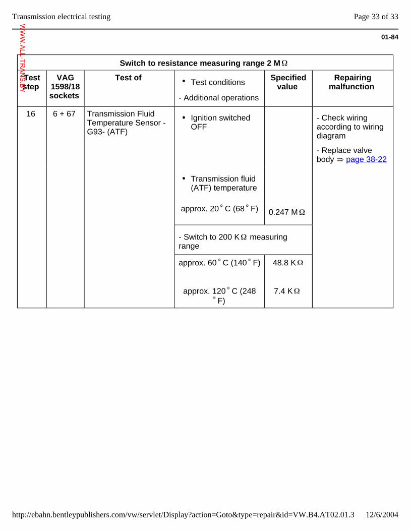
01-84
Switch to resistance measuring range 2 M
Test step
VAG 1598/18 sockets
Test of Test conditions
- Additional operations
Specified value
Repairing malfunction
16 6 + 67 Transmission Fluid Temperature Sensor -G93- (ATF)
Ignition switched OFF
- Check wiring according to wiring diagram
- Replace valve body page 38-22
approx. 20 C (68 F)
Transmission fluid (ATF) temperature
0.247 M
- Switch to 200 K measuring range
approx. 60 C (140 F)
approx. 120 C (248F)
48.8 K
7.4 K
Page 33 of 33Transmission electrical testing
12/6/2004http://ebahn.bentleypublishers.com/vw/servlet/Display?action=Goto&type=repair&id=VW.B4.AT02.01.3
WWW.ALL-TR
ANS.BY
32-1
Torque converter The ATF pump is driven via the torque
converter.
When installing the torque converter, make sure that both drive pins engage in the recesses in the ATF pump inner wheel.
Page 1 of 4Torque converter
12/6/2004http://ebahn.bentleypublishers.com/vw/servlet/Display?action=Goto&type=repair&id=VW.B4.AT02.32.1
WWW.ALL-TR
ANS.BY
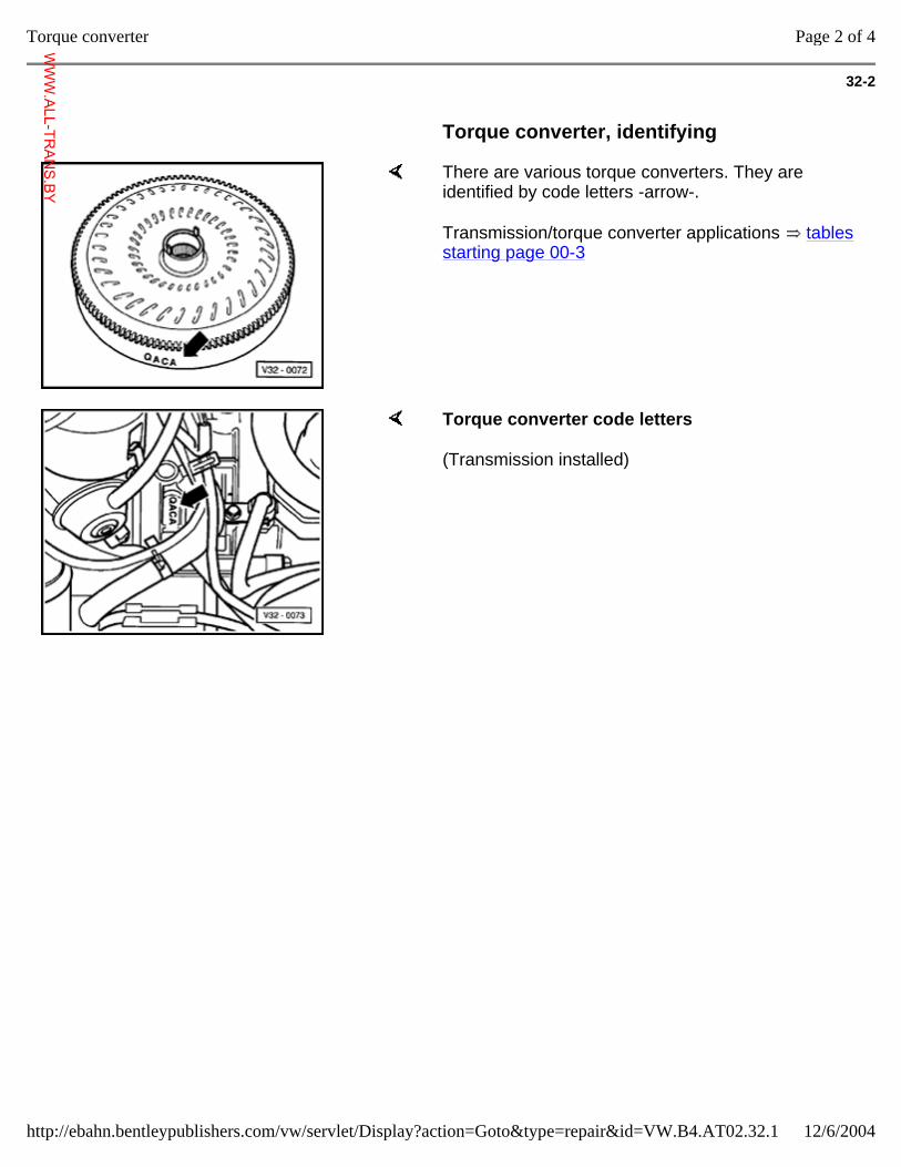
32-2
Torque converter, identifying
There are various torque converters. They are identified by code letters -arrow-.
Transmission/torque converter applications tables starting page 00-3
Torque converter code letters
(Transmission installed)
Page 2 of 4Torque converter
12/6/2004http://ebahn.bentleypublishers.com/vw/servlet/Display?action=Goto&type=repair&id=VW.B4.AT02.32.1
WWW.ALL-TR
ANS.BY
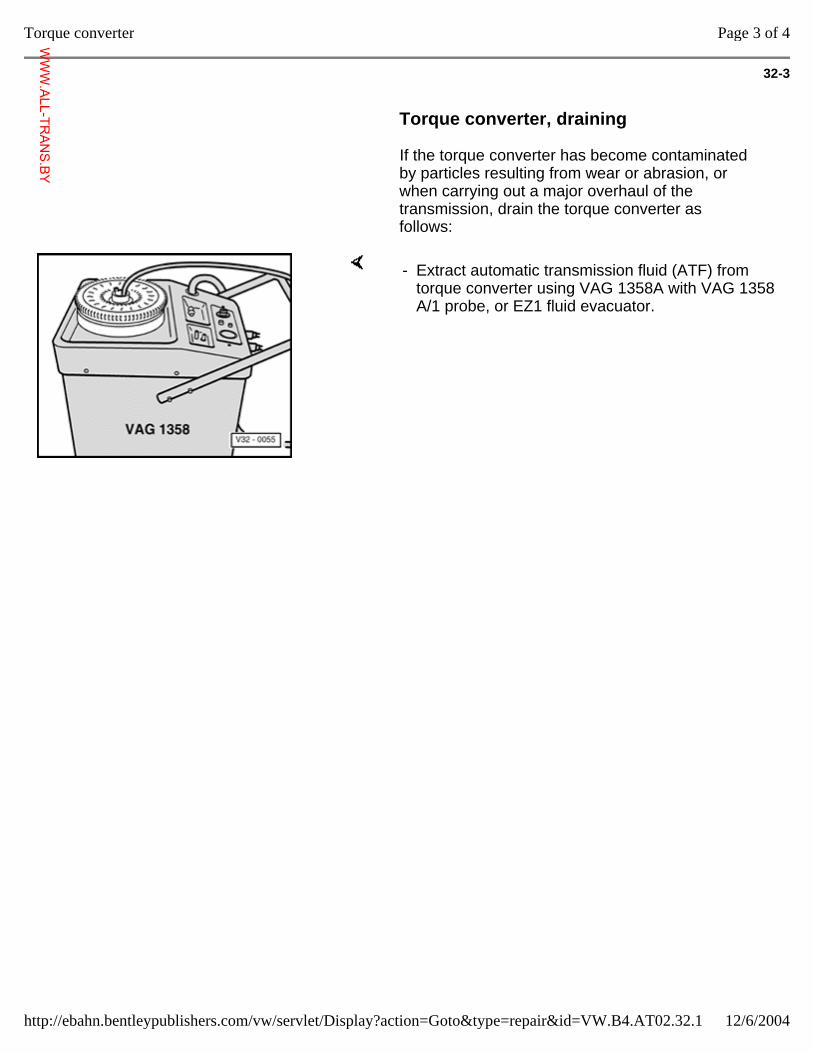
32-3
Torque converter, draining
If the torque converter has become contaminated by particles resulting from wear or abrasion, or when carrying out a major overhaul of the transmission, drain the torque converter as follows:
- Extract automatic transmission fluid (ATF) from torque converter using VAG 1358A with VAG 1358 A/1 probe, or EZ1 fluid evacuator.
Page 3 of 4Torque converter
12/6/2004http://ebahn.bentleypublishers.com/vw/servlet/Display?action=Goto&type=repair&id=VW.B4.AT02.32.1
WWW.ALL-TR
ANS.BY
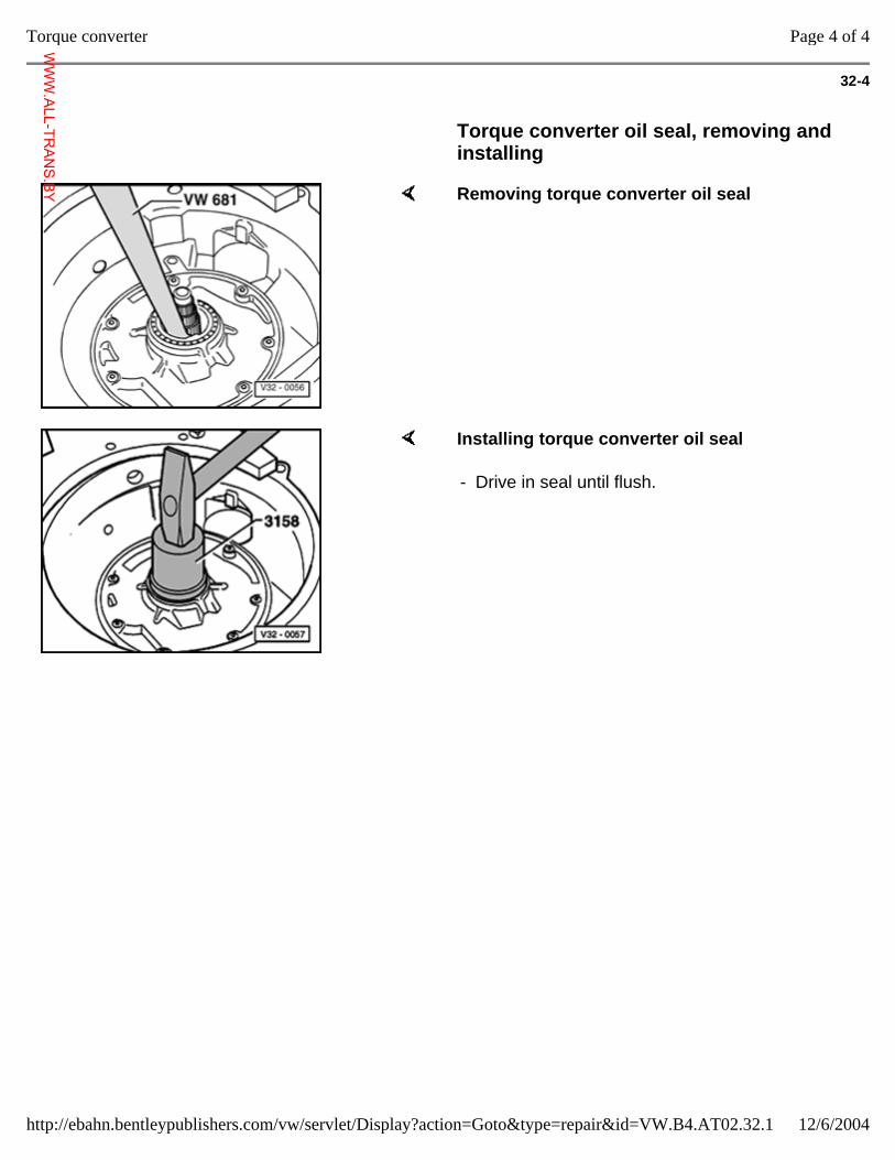
32-4
Torque converter oil seal, removing and installing
Removing torque converter oil seal
Installing torque converter oil seal
- Drive in seal until flush.
Page 4 of 4Torque converter
12/6/2004http://ebahn.bentleypublishers.com/vw/servlet/Display?action=Goto&type=repair&id=VW.B4.AT02.32.1
WWW.ALL-TR
ANS.BY
37-1
Shift mechanism, servicing CAUTION!
Before working on the engine when it is running, move the transmission selector lever into the "P" position and apply the parking brake.
Shift mechanism, checking
Selector lever in "P" position; ignition switched ON
Brake pedal not depressed:
Selector lever is locked and cannot be shifted out of "P" position. Shiftlock Solenoid -N110- blocks selector lever.
Brake pedal depressed:
Shiftlock Solenoid -N110- releases selector lever. It is now possible to shift into a driving gear.
Page 1 of 25Shift mechanism, servicing
12/6/2004http://ebahn.bentleypublishers.com/vw/servlet/Display?action=Goto&type=repair&id=VW.B4.AT02.37.1
WWW.ALL-TR
ANS.BY
37-2
Selector lever in "N" position and ignition switched ON:
Brake pedal not depressed:
Selector lever is locked and cannot be shifted out of "N" position. Shiftlock Solenoid -N110- blocks selector lever.
Brake pedal depressed:
Shiftlock Solenoid -N110- releases selector lever. It is possible to shift into a driving gear.
Note:
The starter must not be able to operate with the selector lever in positions "1," "2," "3," "D" and "R."
When travelling at speeds above 5 km/h (3 mph) and shifting into selector lever position "N" the Shiftlock Solenoid -N110- must not engage and block the selector lever. The selector lever can be shifted into a driving gear.
When travelling at speeds below 5 km/h (3 mph) (almost stopped) and shifting into selector lever position "N", the Shiftlock Solenoid -N110- must not engage until after approx. 1 second. The selector lever cannot be shifted out of the "N" position until the brake pedal is depressed.
Page 2 of 25Shift mechanism, servicing
12/6/2004http://ebahn.bentleypublishers.com/vw/servlet/Display?action=Goto&type=repair&id=VW.B4.AT02.37.1
WWW.ALL-TR
ANS.BY
37-3
Selector lever cable, checking and adjusting
Checking
- Remove selector lever cable combi-bolt from lever/selector shaft.
- Move selector lever from "P" to "1."
Shift mechanism and selector lever cable must move freely. If necessary replace selector lever cable or service shift mechanism.
Always replace selector lever locking washer at transmission lever after dismantling.
Adjusting
Selector lever in "P" position
- Loosen selector lever cable combi-bolt on selector shaft lever.
- Bring selector shaft lever into position "P" on transmission. Locking lever must engage in park lock wheel, both front wheels locked.
- In this position tighten selector shaft lever combi-bolt.
Tightening torque: 25 Nm (18 ft lb)
Page 3 of 25Shift mechanism, servicing
12/6/2004http://ebahn.bentleypublishers.com/vw/servlet/Display?action=Goto&type=repair&id=VW.B4.AT02.37.1
WWW.ALL-TR
ANS.BY
37-4
Ignition lock, checking
- Shift selector lever to "P" position and turn ignition key to end ("OFF") position.
It must only be possible to remove ignition key with selector lever in "P" position.
- Remove ignition key. Selector lever cannot be shifted out of "P" position.
Page 4 of 25Shift mechanism, servicing
12/6/2004http://ebahn.bentleypublishers.com/vw/servlet/Display?action=Goto&type=repair&id=VW.B4.AT02.37.1
WWW.ALL-TR
ANS.BY
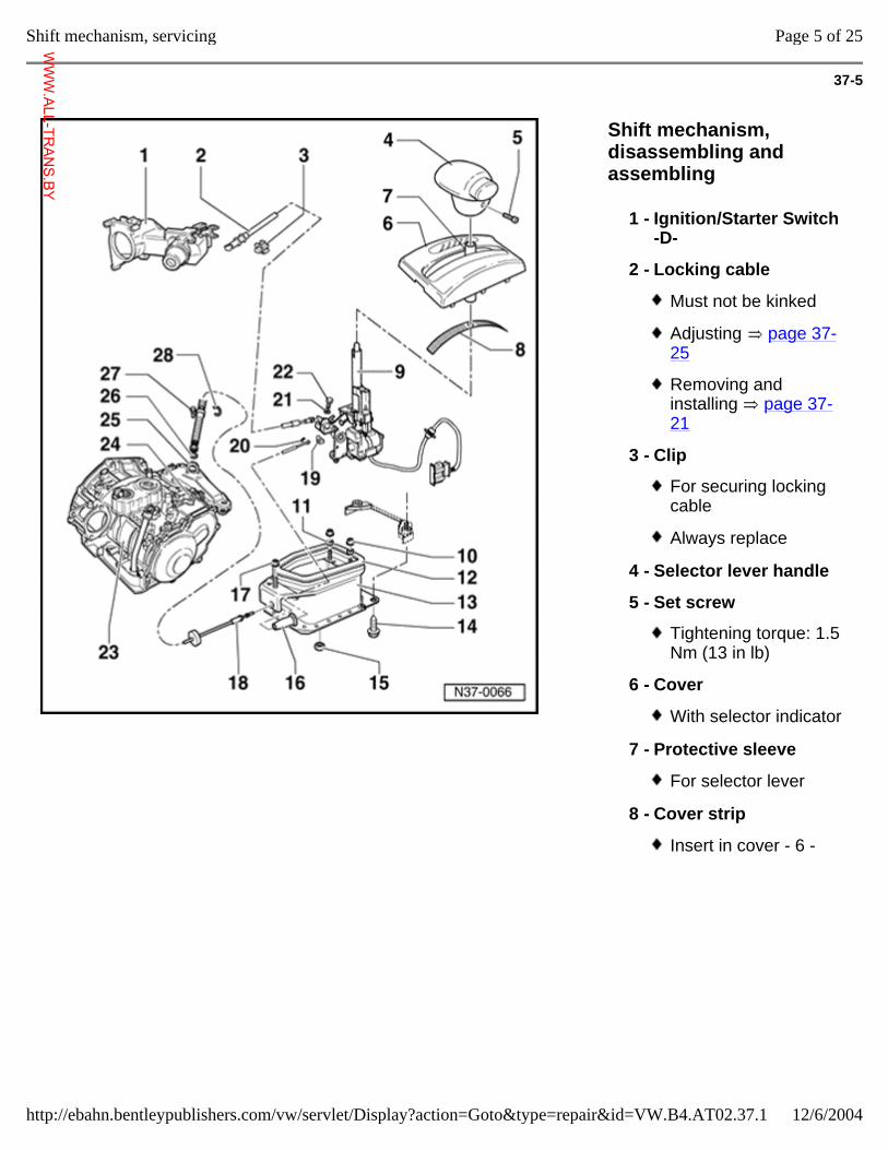
37-5
Shift mechanism, disassembling and assembling
1 - Ignition/Starter Switch -D-
2 - Locking cable
Must not be kinked
Adjusting page 37-25
Removing and installing page 37-21
3 - Clip
For securing locking cable
Always replace
4 - Selector lever handle
5 - Set screw
Tightening torque: 1.5 Nm (13 in lb)
6 - Cover
With selector indicator
7 - Protective sleeve
For selector lever
8 - Cover strip
Insert in cover - 6 -
Page 5 of 25Shift mechanism, servicing
12/6/2004http://ebahn.bentleypublishers.com/vw/servlet/Display?action=Goto&type=repair&id=VW.B4.AT02.37.1
WWW.ALL-TR
ANS.BY
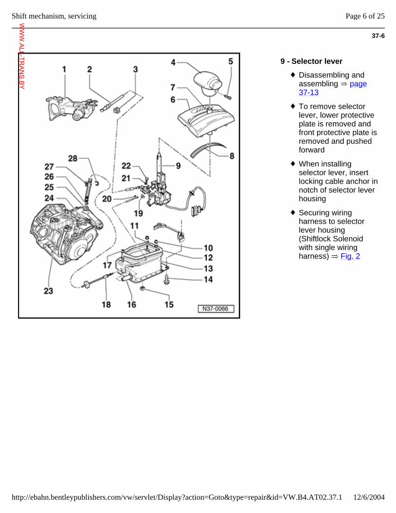
37-6
9 - Selector lever
Disassembling and assembling page 37-13
To remove selector lever, lower protective plate is removed and front protective plate is removed and pushed forward
When installing selector lever, insert locking cable anchor in notch of selector lever housing
Securing wiring harness to selector lever housing (Shiftlock Solenoid with single wiring harness) Fig. 2
Page 6 of 25Shift mechanism, servicing
12/6/2004http://ebahn.bentleypublishers.com/vw/servlet/Display?action=Goto&type=repair&id=VW.B4.AT02.37.1
WWW.ALL-TR
ANS.BY
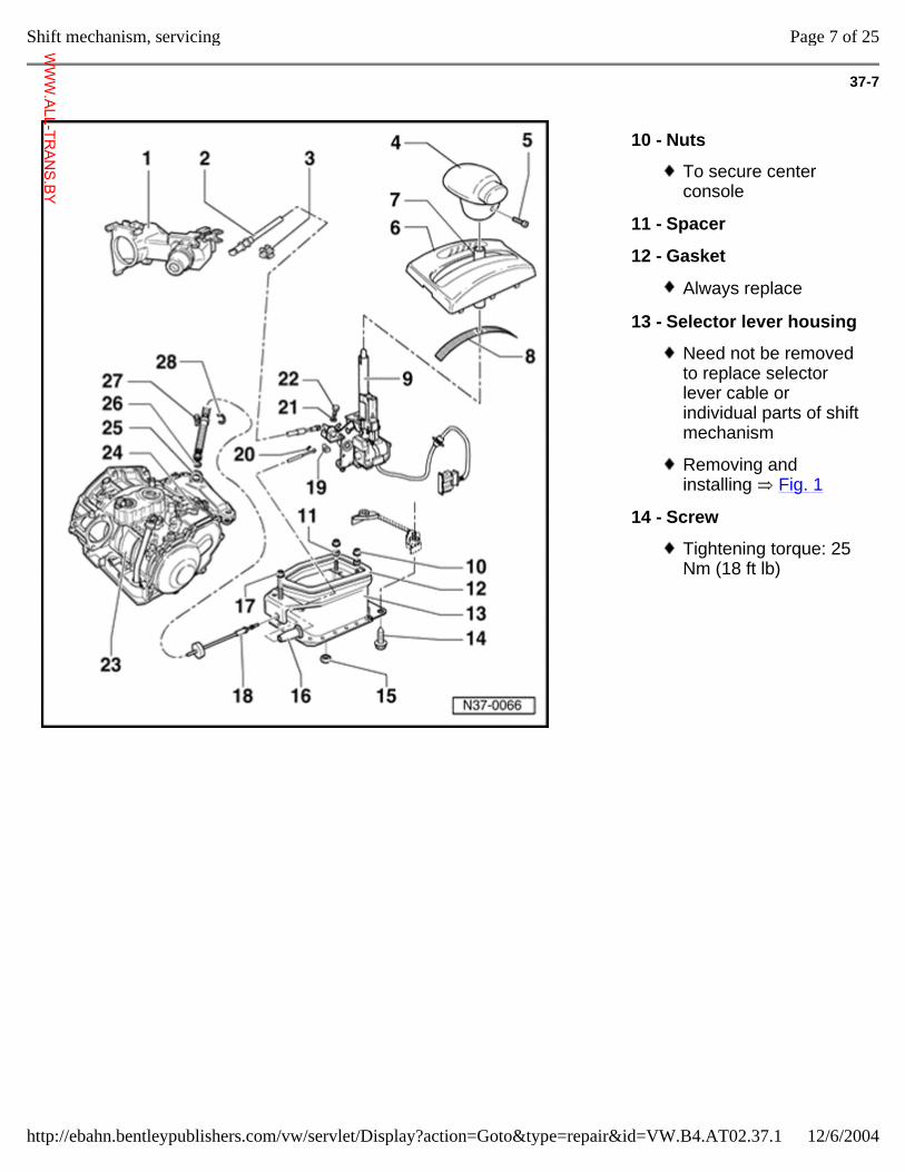
37-7
10 - Nuts
To secure center console
11 - Spacer
12 - Gasket
Always replace
13 - Selector lever housing
Need not be removed to replace selector lever cable or individual parts of shift mechanism
Removing and installing Fig. 1
14 - Screw
Tightening torque: 25 Nm (18 ft lb)
Page 7 of 25Shift mechanism, servicing
12/6/2004http://ebahn.bentleypublishers.com/vw/servlet/Display?action=Goto&type=repair&id=VW.B4.AT02.37.1
WWW.ALL-TR
ANS.BY
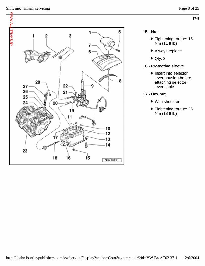
37-8
15 - Nut
Tightening torque: 15 Nm (11 ft lb)
Always replace
Qty. 3
16 - Protective sleeve
Insert into selector lever housing before attaching selector lever cable
17 - Hex nut
With shoulder
Tightening torque: 25 Nm (18 ft lb)
Page 8 of 25Shift mechanism, servicing
12/6/2004http://ebahn.bentleypublishers.com/vw/servlet/Display?action=Goto&type=repair&id=VW.B4.AT02.37.1
WWW.ALL-TR
ANS.BY
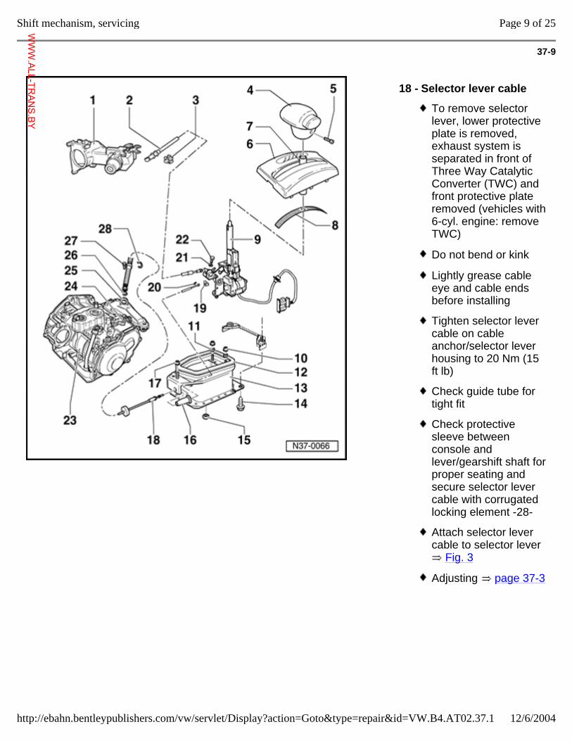
37-9
18 - Selector lever cable
To remove selector lever, lower protective plate is removed, exhaust system is separated in front of Three Way Catalytic Converter (TWC) and front protective plate removed (vehicles with 6-cyl. engine: remove TWC)
Do not bend or kink
Lightly grease cable eye and cable ends before installing
Tighten selector lever cable on cable anchor/selector lever housing to 20 Nm (15 ft lb)
Check guide tube for tight fit
Check protective sleeve between console and lever/gearshift shaft for proper seating and secure selector lever cable with corrugated locking element -28-
Attach selector lever cable to selector lever
Fig. 3
Adjusting page 37-3
Page 9 of 25Shift mechanism, servicing
12/6/2004http://ebahn.bentleypublishers.com/vw/servlet/Display?action=Goto&type=repair&id=VW.B4.AT02.37.1
WWW.ALL-TR
ANS.BY
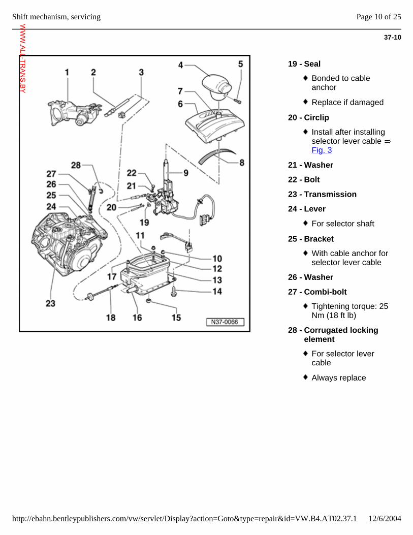
37-10
19 - Seal
Bonded to cable anchor
Replace if damaged
20 - Circlip
Install after installing selector lever cable Fig. 3
21 - Washer
22 - Bolt
23 - Transmission
24 - Lever
For selector shaft
25 - Bracket
With cable anchor for selector lever cable
26 - Washer
27 - Combi-bolt
Tightening torque: 25 Nm (18 ft lb)
28 - Corrugated locking element
For selector lever cable
Always replace
Page 10 of 25Shift mechanism, servicing
12/6/2004http://ebahn.bentleypublishers.com/vw/servlet/Display?action=Goto&type=repair&id=VW.B4.AT02.37.1
WWW.ALL-TR
ANS.BY
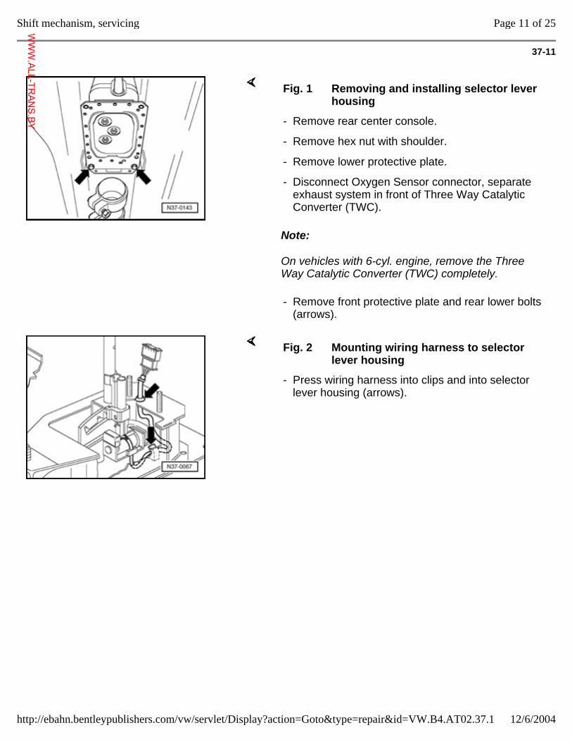
37-11
Note:
On vehicles with 6-cyl. engine, remove the Three Way Catalytic Converter (TWC) completely.
Fig. 1 Removing and installing selector lever housing
- Remove rear center console.
- Remove hex nut with shoulder.
- Remove lower protective plate.
- Disconnect Oxygen Sensor connector, separate exhaust system in front of Three Way Catalytic Converter (TWC).
- Remove front protective plate and rear lower bolts (arrows).
Fig. 2 Mounting wiring harness to selector lever housing
- Press wiring harness into clips and into selector lever housing (arrows).
Page 11 of 25Shift mechanism, servicing
12/6/2004http://ebahn.bentleypublishers.com/vw/servlet/Display?action=Goto&type=repair&id=VW.B4.AT02.37.1
WWW.ALL-TR
ANS.BY
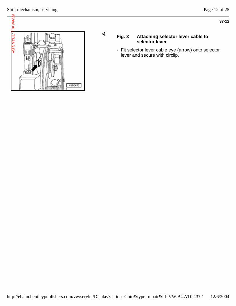
37-12
Fig. 3 Attaching selector lever cable to selector lever
- Fit selector lever cable eye (arrow) onto selector lever and secure with circlip.
Page 12 of 25Shift mechanism, servicing
12/6/2004http://ebahn.bentleypublishers.com/vw/servlet/Display?action=Goto&type=repair&id=VW.B4.AT02.37.1
WWW.ALL-TR
ANS.BY
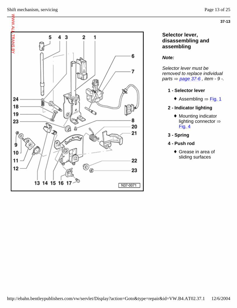
37-13
Selector lever, disassembling and assembling
Note:
Selector lever must be removed to replace individual parts page 37-6 , item - 9 -.
1 - Selector lever
Assembling Fig. 1
2 - Indicator lighting
Mounting indicator lighting connector Fig. 4
3 - Spring
4 - Push rod
Grease in area of sliding surfaces
Page 13 of 25Shift mechanism, servicing
12/6/2004http://ebahn.bentleypublishers.com/vw/servlet/Display?action=Goto&type=repair&id=VW.B4.AT02.37.1
WWW.ALL-TR
ANS.BY
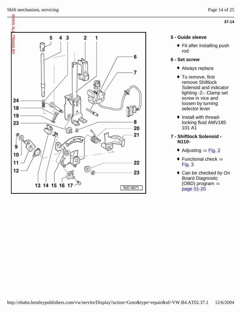
37-14
5 - Guide sleeve
Fit after installing push rod
6 - Set screw
Always replace
To remove, first remove Shiftlock Solenoid and indicator lighting -2-. Clamp set screw in vice and loosen by turning selector lever
Install with thread-locking fluid AMV185 101 A1
7 - Shiftlock Solenoid -N110-
Adjusting Fig. 2
Functional check Fig. 3
Can be checked by On Board Diagnostic (OBD) program page 01-20
Page 14 of 25Shift mechanism, servicing
12/6/2004http://ebahn.bentleypublishers.com/vw/servlet/Display?action=Goto&type=repair&id=VW.B4.AT02.37.1
WWW.ALL-TR
ANS.BY
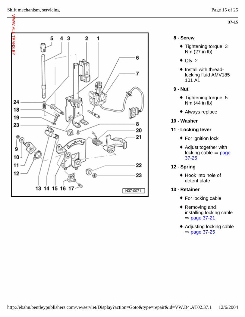
37-15
8 - Screw
Tightening torque: 3 Nm (27 in lb)
Qty. 2
Install with thread-locking fluid AMV185 101 A1
9 - Nut
Tightening torque: 5 Nm (44 in lb)
Always replace
10 - Washer
11 - Locking lever
For ignition lock
Adjust together with locking cable page 37-25
12 - Spring
Hook into hole of detent plate
13 - Retainer
For locking cable
Removing and installing locking cable
page 37-21
Adjusting locking cable page 37-25
Page 15 of 25Shift mechanism, servicing
12/6/2004http://ebahn.bentleypublishers.com/vw/servlet/Display?action=Goto&type=repair&id=VW.B4.AT02.37.1
WWW.ALL-TR
ANS.BY
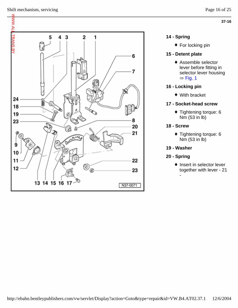
37-16
14 - Spring
For locking pin
15 - Detent plate
Assemble selector lever before fitting in selector lever housing
Fig. 1
16 - Locking pin
With bracket
17 - Socket-head screw
Tightening torque: 6 Nm (53 in lb)
18 - Screw
Tightening torque: 6 Nm (53 in lb)
19 - Washer
20 - Spring
Insert in selector lever together with lever - 21 -
Page 16 of 25Shift mechanism, servicing
12/6/2004http://ebahn.bentleypublishers.com/vw/servlet/Display?action=Goto&type=repair&id=VW.B4.AT02.37.1
WWW.ALL-TR
ANS.BY
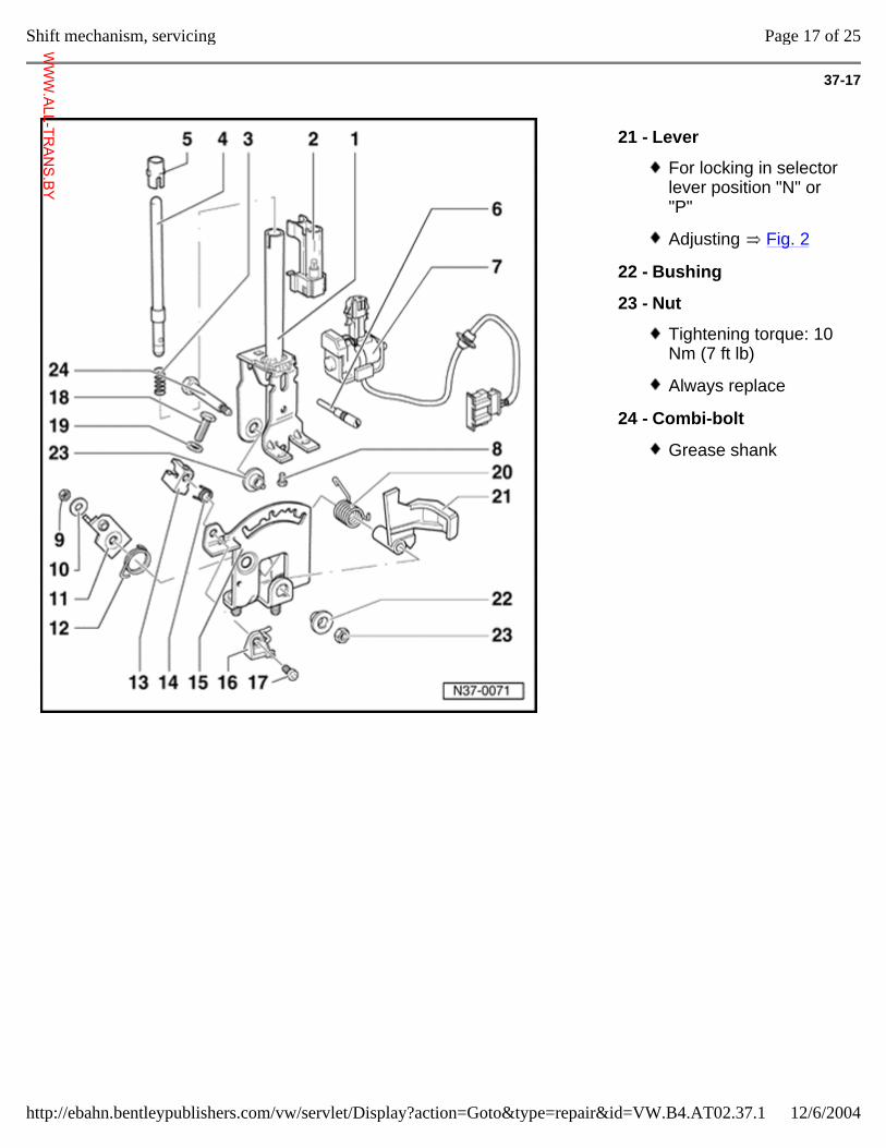
37-17
21 - Lever
For locking in selector lever position "N" or "P"
Adjusting Fig. 2
22 - Bushing
23 - Nut
Tightening torque: 10 Nm (7 ft lb)
Always replace
24 - Combi-bolt
Grease shank
Page 17 of 25Shift mechanism, servicing
12/6/2004http://ebahn.bentleypublishers.com/vw/servlet/Display?action=Goto&type=repair&id=VW.B4.AT02.37.1
WWW.ALL-TR
ANS.BY
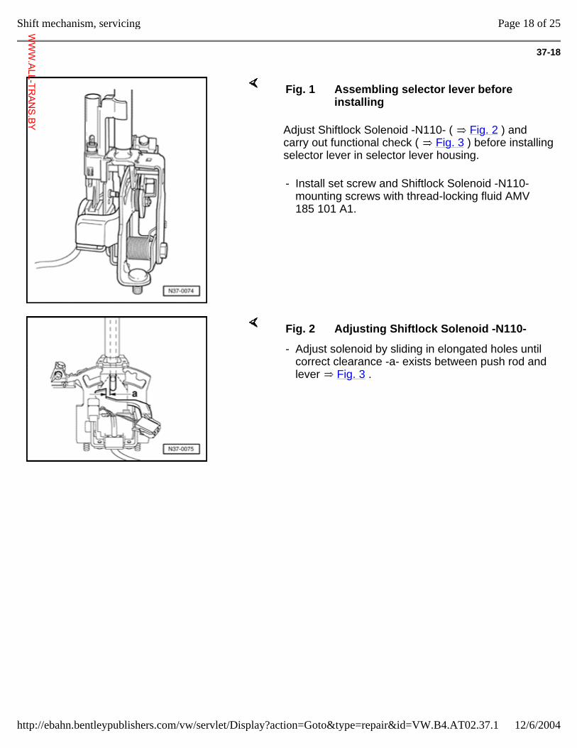
37-18
Adjust Shiftlock Solenoid -N110- ( Fig. 2 ) and carry out functional check ( Fig. 3 ) before installing selector lever in selector lever housing.
Fig. 1 Assembling selector lever before installing
- Install set screw and Shiftlock Solenoid -N110- mounting screws with thread-locking fluid AMV 185 101 A1.
Fig. 2 Adjusting Shiftlock Solenoid -N110-
- Adjust solenoid by sliding in elongated holes until correct clearance -a- exists between push rod and lever Fig. 3 .
Page 18 of 25Shift mechanism, servicing
12/6/2004http://ebahn.bentleypublishers.com/vw/servlet/Display?action=Goto&type=repair&id=VW.B4.AT02.37.1
WWW.ALL-TR
ANS.BY
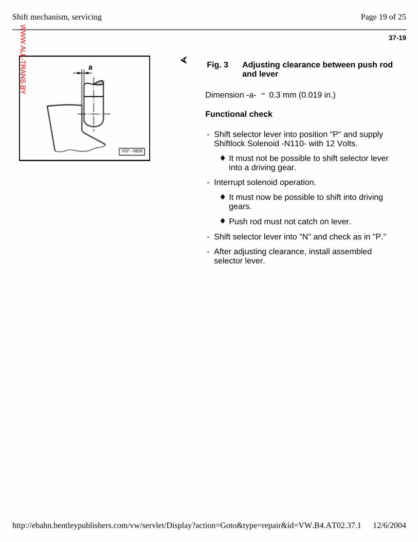
37-19
Dimension -a- 0.3 mm (0.019 in.)
Functional check
Fig. 3 Adjusting clearance between push rod and lever
- Shift selector lever into position "P" and supply Shiftlock Solenoid -N110- with 12 Volts.
It must not be possible to shift selector lever into a driving gear.
- Interrupt solenoid operation.
It must now be possible to shift into driving gears.
Push rod must not catch on lever.
- Shift selector lever into "N" and check as in "P."
- After adjusting clearance, install assembled selector lever.
Page 19 of 25Shift mechanism, servicing
12/6/2004http://ebahn.bentleypublishers.com/vw/servlet/Display?action=Goto&type=repair&id=VW.B4.AT02.37.1
WWW.ALL-TR
ANS.BY
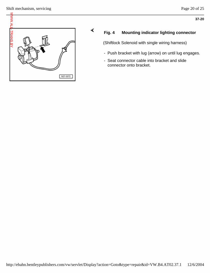
37-20
(Shiftlock Solenoid with single wiring harness)
Fig. 4 Mounting indicator lighting connector
- Push bracket with lug (arrow) on until lug engages.
- Seat connector cable into bracket and slide connector onto bracket.
Page 20 of 25Shift mechanism, servicing
12/6/2004http://ebahn.bentleypublishers.com/vw/servlet/Display?action=Goto&type=repair&id=VW.B4.AT02.37.1
WWW.ALL-TR
ANS.BY
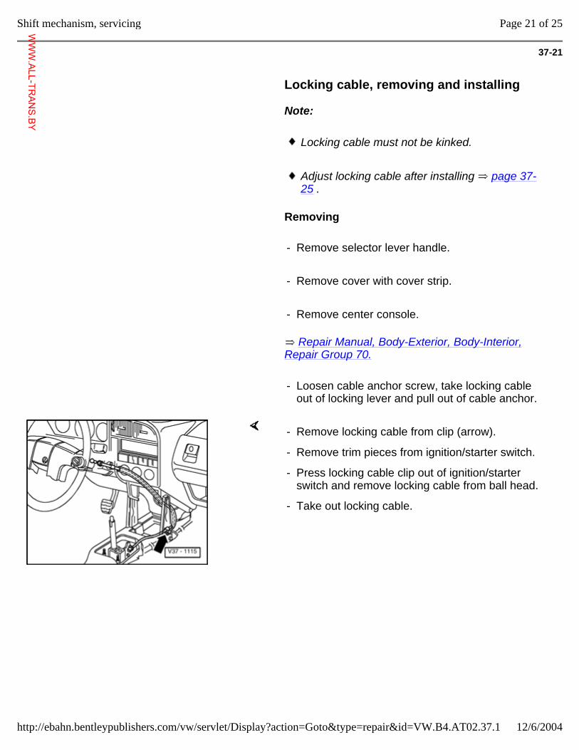
37-21
Locking cable, removing and installing
Note:
Locking cable must not be kinked.
Adjust locking cable after installing page 37-25 .
Removing
- Remove selector lever handle.
- Remove cover with cover strip.
- Remove center console.
Repair Manual, Body-Exterior, Body-Interior, Repair Group 70.
- Loosen cable anchor screw, take locking cable out of locking lever and pull out of cable anchor.
- Remove locking cable from clip (arrow).
- Remove trim pieces from ignition/starter switch.
- Press locking cable clip out of ignition/starter switch and remove locking cable from ball head.
- Take out locking cable.
Page 21 of 25Shift mechanism, servicing
12/6/2004http://ebahn.bentleypublishers.com/vw/servlet/Display?action=Goto&type=repair&id=VW.B4.AT02.37.1
WWW.ALL-TR
ANS.BY
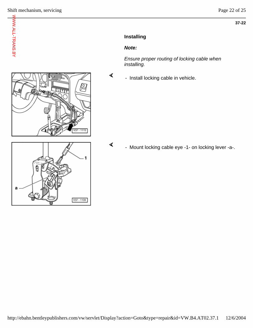
37-22
Installing
Note:
Ensure proper routing of locking cable when installing.
- Install locking cable in vehicle.
- Mount locking cable eye -1- on locking lever -a-.
Page 22 of 25Shift mechanism, servicing
12/6/2004http://ebahn.bentleypublishers.com/vw/servlet/Display?action=Goto&type=repair&id=VW.B4.AT02.37.1
WWW.ALL-TR
ANS.BY
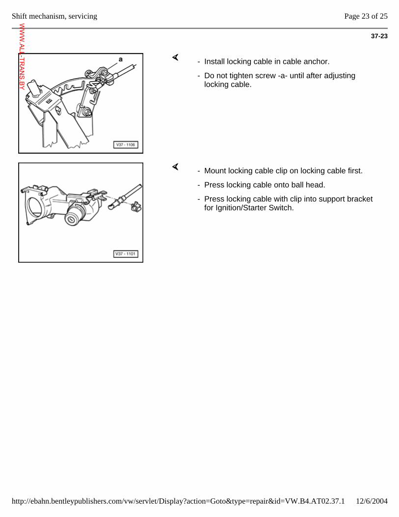
37-23
- Install locking cable in cable anchor.
- Do not tighten screw -a- until after adjusting locking cable.
- Mount locking cable clip on locking cable first.
- Press locking cable onto ball head.
- Press locking cable with clip into support bracket for Ignition/Starter Switch.
Page 23 of 25Shift mechanism, servicing
12/6/2004http://ebahn.bentleypublishers.com/vw/servlet/Display?action=Goto&type=repair&id=VW.B4.AT02.37.1
WWW.ALL-TR
ANS.BY
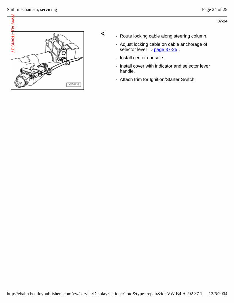
37-24
- Route locking cable along steering column.
- Adjust locking cable on cable anchorage of selector lever page 37-25 .
- Install center console.
- Install cover with indicator and selector lever handle.
- Attach trim for Ignition/Starter Switch.
Page 24 of 25Shift mechanism, servicing
12/6/2004http://ebahn.bentleypublishers.com/vw/servlet/Display?action=Goto&type=repair&id=VW.B4.AT02.37.1
WWW.ALL-TR
ANS.BY
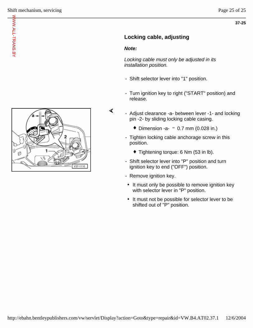
37-25
Locking cable, adjusting
Note:
Locking cable must only be adjusted in its installation position.
- Shift selector lever into "1" position.
- Turn ignition key to right ("START" position) and release.
- Adjust clearance -a- between lever -1- and locking pin -2- by sliding locking cable casing.
Dimension -a- 0.7 mm (0.028 in.)
- Tighten locking cable anchorage screw in this position.
Tightening torque: 6 Nm (53 in lb).
- Shift selector lever into "P" position and turn ignition key to end ("OFF") position.
- Remove ignition key.
It must only be possible to remove ignition key with selector lever in "P" position.
It must not be possible for selector lever to be shifted out of "P" position.
Page 25 of 25Shift mechanism, servicing
12/6/2004http://ebahn.bentleypublishers.com/vw/servlet/Display?action=Goto&type=repair&id=VW.B4.AT02.37.1
WWW.ALL-TR
ANS.BY
37-26
Transmission, checking Shift points, checking
Checking shift points, page 37-27
Stall speed, checking
Measuring stall speed, page 37-30
Main pressure, measuring
Measuring main pressure, page 37-32
Page 1 of 8Transmission, checking
12/6/2004http://ebahn.bentleypublishers.com/vw/servlet/Display?action=Goto&type=repair&id=VW.B4.AT02.37.2
WWW.ALL-TR
ANS.BY
37-27
Shift points, checking
Test requirements
Carry out On Board Diagnostic program
Repair Group 01
- Diagnostic Trouble Code (DTC) Memory interrogated
- System in basic setting
Check transmission fluid (ATF) level
Page 37-43
Check engine settings
Repair Manual for the appropriate engine, Fuel Injection & Ignition, Repair Group 24
Page 2 of 8Transmission, checking
12/6/2004http://ebahn.bentleypublishers.com/vw/servlet/Display?action=Goto&type=repair&id=VW.B4.AT02.37.2
WWW.ALL-TR
ANS.BY
37-28
Transmission shifts too early or too late into the next gear
When checking the shift points one should note that the Speedometer can deviate from the specified figure within the permissible tolerance.
In the tables, the gear shifts are listed according to transmission code letters.
H = Hydraulic shift
M = Mechanical shift
The electronic program switch is built into the Transmission Control Module (TCM). The "ECO" or "Sport" program will be automatically selected by the TCM according to the speed at which the Accelerator Pedal is depressed.
For transmissions with the electronic program switch only kick down shift points are given.
To check the shift points connect VAG 1551 Scan Tool (ST).
Repair Group 01, Reading measured value block.
Page 3 of 8Transmission, checking
12/6/2004http://ebahn.bentleypublishers.com/vw/servlet/Display?action=Goto&type=repair&id=VW.B4.AT02.37.2
WWW.ALL-TR
ANS.BY
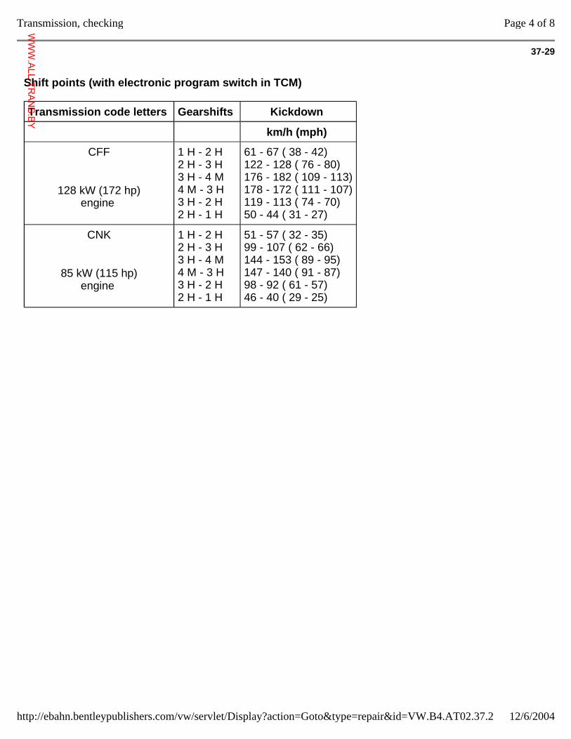
37-29
Shift points (with electronic program switch in TCM)
Transmission code letters Gearshifts Kickdown
km/h (mph)
CFF
128 kW (172 hp) engine
1 H - 2 H 2 H - 3 H 3 H - 4 M 4 M - 3 H 3 H - 2 H 2 H - 1 H
61 - 67 ( 38 - 42) 122 - 128 ( 76 - 80) 176 - 182 ( 109 - 113) 178 - 172 ( 111 - 107) 119 - 113 ( 74 - 70) 50 - 44 ( 31 - 27)
CNK
85 kW (115 hp) engine
1 H - 2 H 2 H - 3 H 3 H - 4 M 4 M - 3 H 3 H - 2 H 2 H - 1 H
51 - 57 ( 32 - 35) 99 - 107 ( 62 - 66) 144 - 153 ( 89 - 95) 147 - 140 ( 91 - 87) 98 - 92 ( 61 - 57) 46 - 40 ( 29 - 25)
Page 4 of 8Transmission, checking
12/6/2004http://ebahn.bentleypublishers.com/vw/servlet/Display?action=Goto&type=repair&id=VW.B4.AT02.37.2
WWW.ALL-TR
ANS.BY
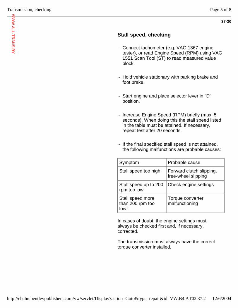
37-30
Stall speed, checking
- Connect tachometer (e.g. VAG 1367 engine tester), or read Engine Speed (RPM) using VAG 1551 Scan Tool (ST) to read measured value block.
- Hold vehicle stationary with parking brake and foot brake.
- Start engine and place selector lever in "D" position.
- Increase Engine Speed (RPM) briefly (max. 5 seconds). When doing this the stall speed listed in the table must be attained. If necessary, repeat test after 20 seconds.
- If the final specified stall speed is not attained, the following malfunctions are probable causes:
Symptom Probable cause
Stall speed too high: Forward clutch slipping, free-wheel slipping
Stall speed up to 200 rpm too low:
Check engine settings
Stall speed more than 200 rpm too low:
Torque converter malfunctioning
In cases of doubt, the engine settings must always be checked first and, if necessary, corrected.
The transmission must always have the correct torque converter installed.
Page 5 of 8Transmission, checking
12/6/2004http://ebahn.bentleypublishers.com/vw/servlet/Display?action=Goto&type=repair&id=VW.B4.AT02.37.2
WWW.ALL-TR
ANS.BY
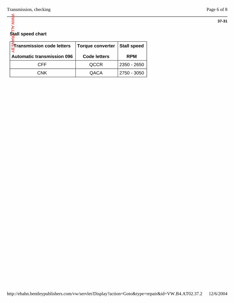
37-31
Stall speed chart
Transmission code letters
Automatic transmission 096
Torque converter
Code letters
Stall speed
RPM
CFF QCCR 2350 - 2650
CNK QACA 2750 - 3050
Page 6 of 8Transmission, checking
12/6/2004http://ebahn.bentleypublishers.com/vw/servlet/Display?action=Goto&type=repair&id=VW.B4.AT02.37.2
WWW.ALL-TR
ANS.BY
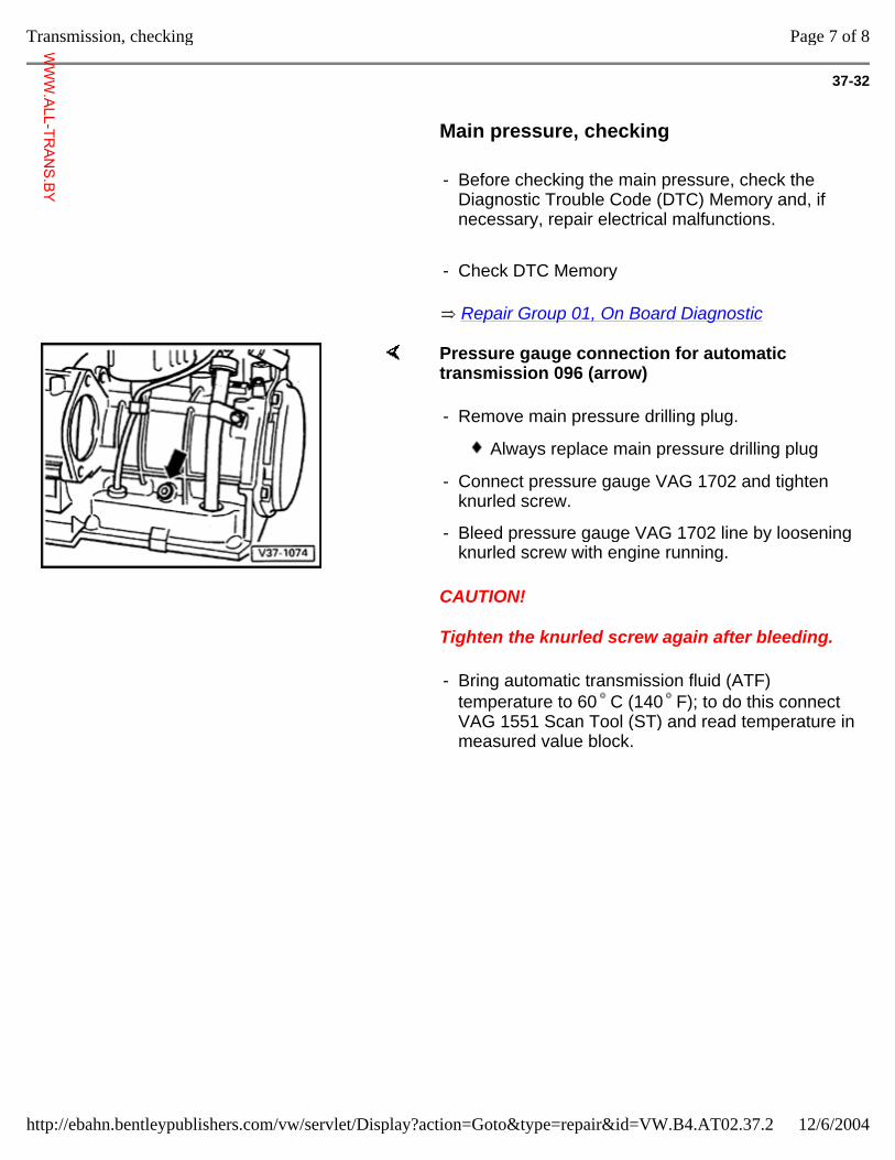
37-32
Main pressure, checking
- Before checking the main pressure, check the Diagnostic Trouble Code (DTC) Memory and, if necessary, repair electrical malfunctions.
- Check DTC Memory
Repair Group 01, On Board Diagnostic
Pressure gauge connection for automatic transmission 096 (arrow)
CAUTION!
Tighten the knurled screw again after bleeding.
- Remove main pressure drilling plug.
Always replace main pressure drilling plug
- Connect pressure gauge VAG 1702 and tighten knurled screw.
- Bleed pressure gauge VAG 1702 line by loosening knurled screw with engine running.
- Bring automatic transmission fluid (ATF) temperature to 60 C (140 F); to do this connect VAG 1551 Scan Tool (ST) and read temperature in measured value block.
Page 7 of 8Transmission, checking
12/6/2004http://ebahn.bentleypublishers.com/vw/servlet/Display?action=Goto&type=repair&id=VW.B4.AT02.37.2
WWW.ALL-TR
ANS.BY
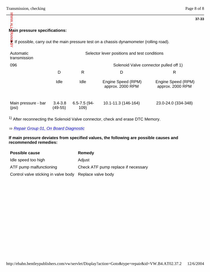
37-33
Main pressure specifications:
If possible, carry out the main pressure test on a chassis dynamometer (rolling road).
Automatic transmission
Selector lever positions and test conditions
096 Solenoid Valve connector pulled off 1)
D
Idle
R
Idle
D
Engine Speed (RPM) approx. 2000 RPM
R
Engine Speed (RPM) approx. 2000 RPM
Main pressure - bar (psi)
3.4-3.8 (49-55)
6.5-7.5 (94-109)
10.1-11.3 (146-164) 23.0-24.0 (334-348)
1) After reconnecting the Solenoid Valve connector, check and erase DTC Memory.
Repair Group 01, On Board Diagnostic
If main pressure deviates from specified values, the following are possible causes and recommended remedies:
Possible cause Remedy
Idle speed too high Adjust
ATF pump malfunctioning Check ATF pump replace if necessary
Control valve sticking in valve body Replace valve body
Page 8 of 8Transmission, checking
12/6/2004http://ebahn.bentleypublishers.com/vw/servlet/Display?action=Goto&type=repair&id=VW.B4.AT02.37.2
WWW.ALL-TR
ANS.BY
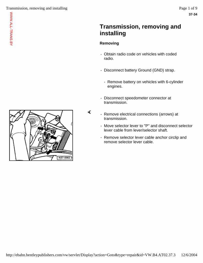
37-34
Transmission, removing and installing
Removing
- Obtain radio code on vehicles with coded radio.
- Disconnect battery Ground (GND) strap.
- Remove battery on vehicles with 6-cylinder engines.
- Disconnect speedometer connector at transmission.
- Remove electrical connections (arrows) at transmission.
- Move selector lever to "P" and disconnect selector lever cable from lever/selector shaft.
- Remove selector lever cable anchor circlip and remove selector lever cable.
Page 1 of 9Transmission, removing and installing
12/6/2004http://ebahn.bentleypublishers.com/vw/servlet/Display?action=Goto&type=repair&id=VW.B4.AT02.37.3
WWW.ALL-TR
ANS.BY
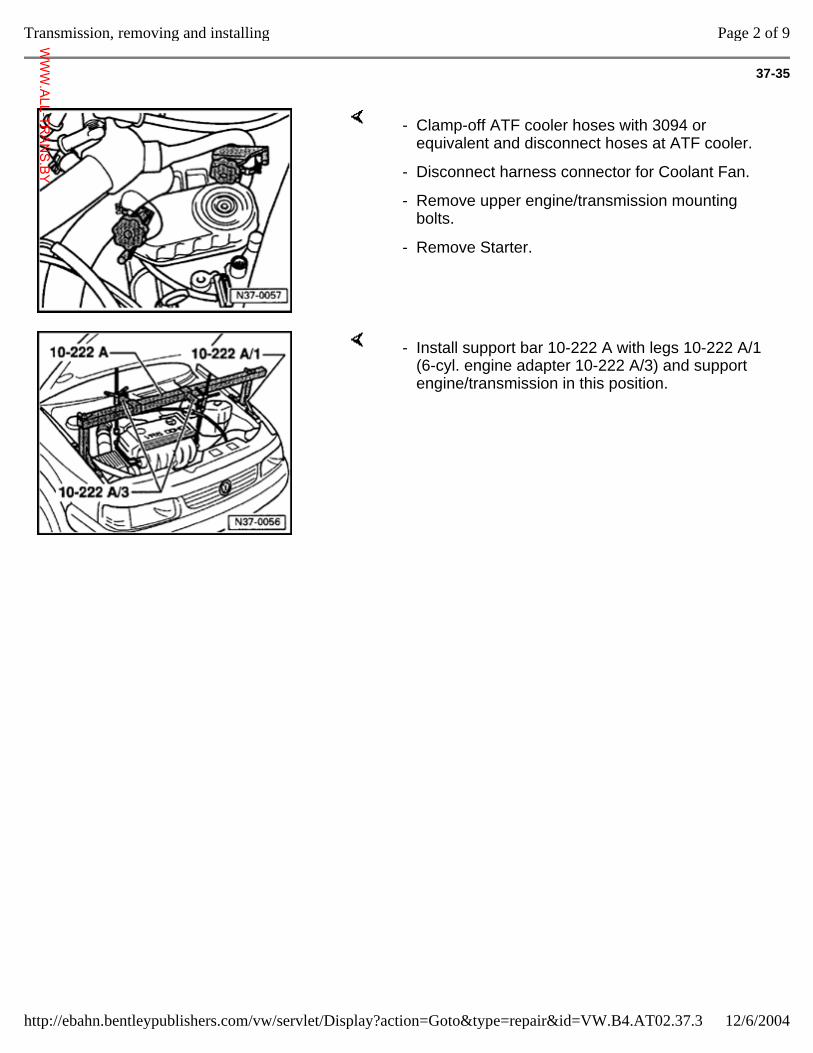
37-35
- Clamp-off ATF cooler hoses with 3094 or equivalent and disconnect hoses at ATF cooler.
- Disconnect harness connector for Coolant Fan.
- Remove upper engine/transmission mounting bolts.
- Remove Starter.
- Install support bar 10-222 A with legs 10-222 A/1 (6-cyl. engine adapter 10-222 A/3) and support engine/transmission in this position.
Page 2 of 9Transmission, removing and installing
12/6/2004http://ebahn.bentleypublishers.com/vw/servlet/Display?action=Goto&type=repair&id=VW.B4.AT02.37.3
WWW.ALL-TR
ANS.BY
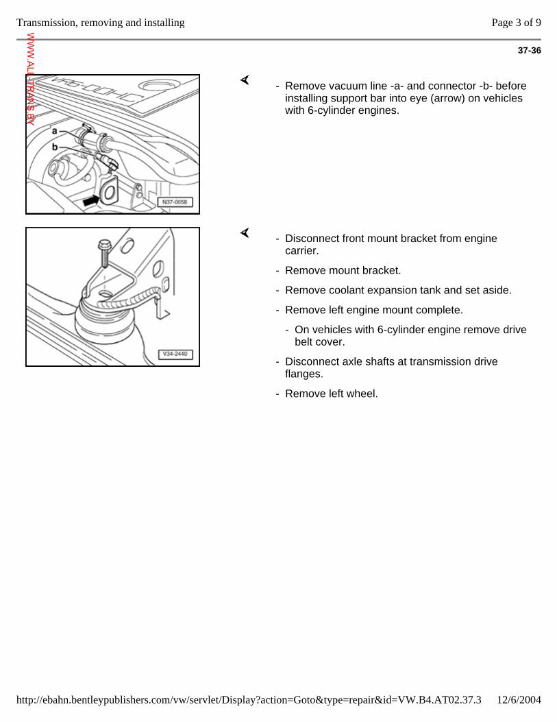
37-36
- Remove vacuum line -a- and connector -b- before installing support bar into eye (arrow) on vehicles with 6-cylinder engines.
- Disconnect front mount bracket from engine carrier.
- Remove mount bracket.
- Remove coolant expansion tank and set aside.
- Remove left engine mount complete.
- On vehicles with 6-cylinder engine remove drive belt cover.
- Disconnect axle shafts at transmission drive flanges.
- Remove left wheel.
Page 3 of 9Transmission, removing and installing
12/6/2004http://ebahn.bentleypublishers.com/vw/servlet/Display?action=Goto&type=repair&id=VW.B4.AT02.37.3
WWW.ALL-TR
ANS.BY
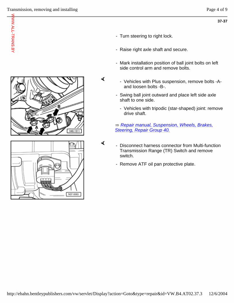
37-37
- Turn steering to right lock.
- Raise right axle shaft and secure.
- Mark installation position of ball joint bolts on left side control arm and remove bolts.
Repair manual, Suspension, Wheels, Brakes, Steering, Repair Group 40.
- Vehicles with Plus suspension, remove bolts -A- and loosen bolts -B-.
- Swing ball joint outward and place left side axle shaft to one side.
- Vehicles with tripodic (star-shaped) joint: remove drive shaft.
- Disconnect harness connector from Multi-function Transmission Range (TR) Switch and remove switch.
- Remove ATF oil pan protective plate.
Page 4 of 9Transmission, removing and installing
12/6/2004http://ebahn.bentleypublishers.com/vw/servlet/Display?action=Goto&type=repair&id=VW.B4.AT02.37.3
WWW.ALL-TR
ANS.BY
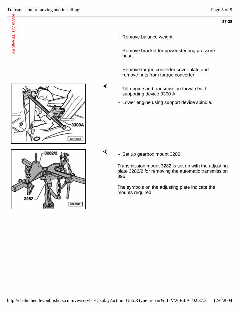
37-38
- Remove balance weight.
- Remove bracket for power steering pressure hose.
- Remove torque converter cover plate and remove nuts from torque converter.
- Tilt engine and transmission forward with supporting device 3300 A.
- Lower engine using support device spindle.
Transmission mount 3282 is set up with the adjusting plate 3282/2 for removing the automatic transmission 096.
The symbols on the adjusting plate indicate the mounts required.
- Set up gearbox mount 3282.
Page 5 of 9Transmission, removing and installing
12/6/2004http://ebahn.bentleypublishers.com/vw/servlet/Display?action=Goto&type=repair&id=VW.B4.AT02.37.3
WWW.ALL-TR
ANS.BY
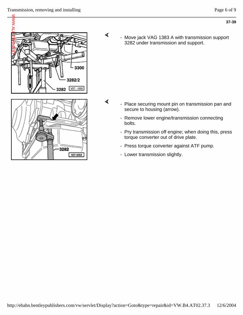
37-39
- Move jack VAG 1383 A with transmission support 3282 under transmission and support.
- Place securing mount pin on transmission pan and secure to housing (arrow).
- Remove lower engine/transmission connecting bolts.
- Pry transmission off engine; when doing this, press torque converter out of drive plate.
- Press torque converter against ATF pump.
- Lower transmission slightly.
Page 6 of 9Transmission, removing and installing
12/6/2004http://ebahn.bentleypublishers.com/vw/servlet/Display?action=Goto&type=repair&id=VW.B4.AT02.37.3
WWW.ALL-TR
ANS.BY
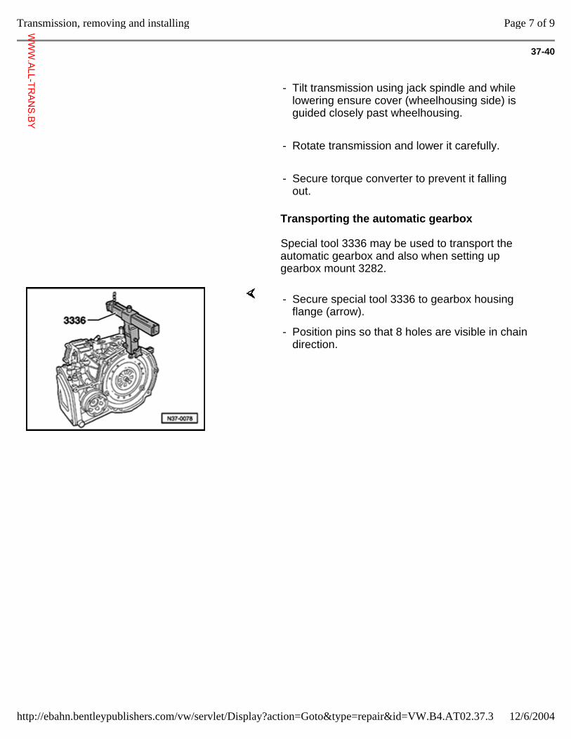
37-40
- Tilt transmission using jack spindle and while lowering ensure cover (wheelhousing side) is guided closely past wheelhousing.
- Rotate transmission and lower it carefully.
- Secure torque converter to prevent it falling out.
Transporting the automatic gearbox
Special tool 3336 may be used to transport the automatic gearbox and also when setting up gearbox mount 3282.
- Secure special tool 3336 to gearbox housing flange (arrow).
- Position pins so that 8 holes are visible in chain direction.
Page 7 of 9Transmission, removing and installing
12/6/2004http://ebahn.bentleypublishers.com/vw/servlet/Display?action=Goto&type=repair&id=VW.B4.AT02.37.3
WWW.ALL-TR
ANS.BY
37-41
Installing
Installation is carried out in the reverse order.
When installing the torque converter, ensure that both drive pins engage in the ATF pump inner wheel recesses.
- Before installing, ensure that dowel sleeves for aligning the engine and transmission are correctly located.
- Replace selector cable anchor locking washer.
- Check selector lever cable adjustment, adjust if necessary page 37-3 .
Page 8 of 9Transmission, removing and installing
12/6/2004http://ebahn.bentleypublishers.com/vw/servlet/Display?action=Goto&type=repair&id=VW.B4.AT02.37.3
WWW.ALL-TR
ANS.BY
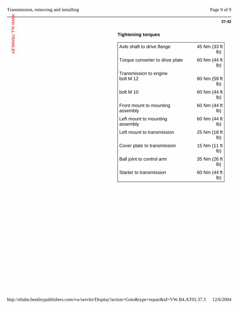
37-42
Tightening torques
Axle shaft to drive flange 45 Nm (33 ft lb)
Torque converter to drive plate 60 Nm (44 ft lb)
Transmission to engine bolt M 12
80 Nm (59 ft
lb)
bolt M 10 60 Nm (44 ft lb)
Front mount to mounting assembly
60 Nm (44 ft lb)
Left mount to mounting assembly
60 Nm (44 ft lb)
Left mount to transmission 25 Nm (18 ft lb)
Cover plate to transmission 15 Nm (11 ft lb)
Ball joint to control arm 35 Nm (26 ft lb)
Starter to transmission 60 Nm (44 ft lb)
Page 9 of 9Transmission, removing and installing
12/6/2004http://ebahn.bentleypublishers.com/vw/servlet/Display?action=Goto&type=repair&id=VW.B4.AT02.37.3
WWW.ALL-TR
ANS.BY
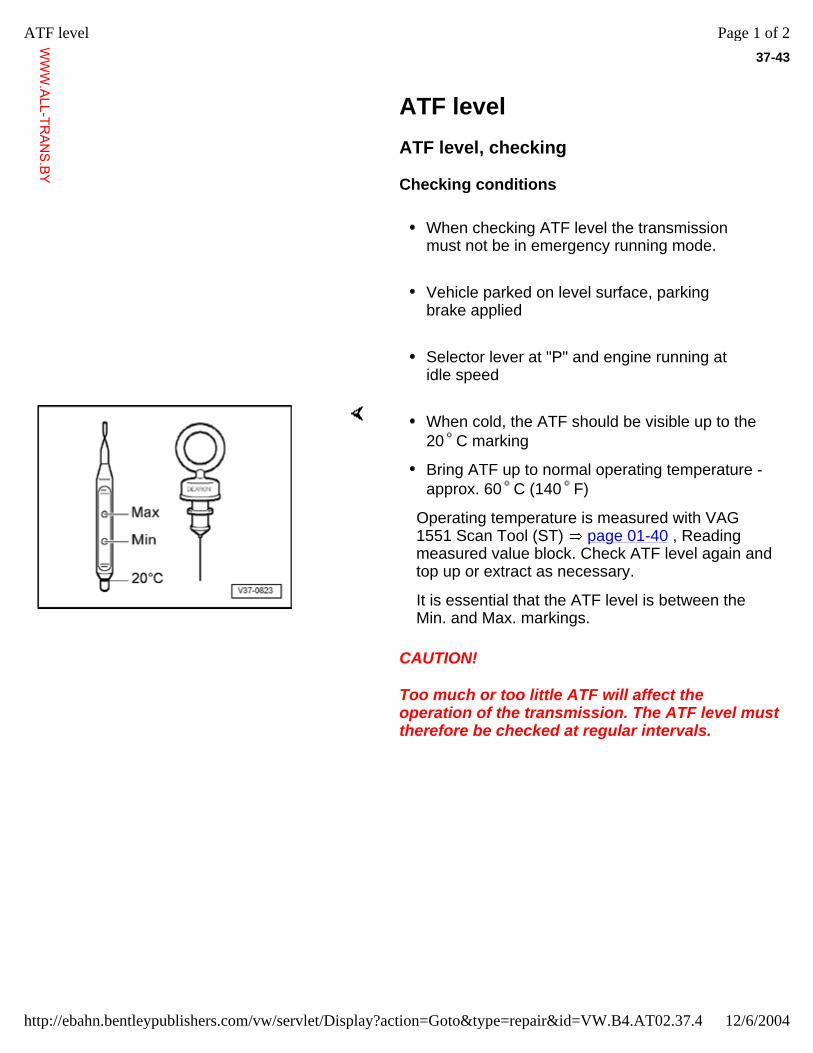
37-43
ATF level ATF level, checking
Checking conditions
When checking ATF level the transmission must not be in emergency running mode.
Vehicle parked on level surface, parking brake applied
Selector lever at "P" and engine running at idle speed
CAUTION!
Too much or too little ATF will affect the operation of the transmission. The ATF level must therefore be checked at regular intervals.
When cold, the ATF should be visible up to the 20 C marking
Bring ATF up to normal operating temperature - approx. 60 C (140 F)
Operating temperature is measured with VAG 1551 Scan Tool (ST) page 01-40 , Reading measured value block. Check ATF level again and top up or extract as necessary.
It is essential that the ATF level is between the Min. and Max. markings.
Page 1 of 2ATF level
12/6/2004http://ebahn.bentleypublishers.com/vw/servlet/Display?action=Goto&type=repair&id=VW.B4.AT02.37.4
WWW.ALL-TR
ANS.BY
37-44
ATF, topping up
CAUTION!
Too much ATF will cause transmission malfunctions and must therefore be extracted. This can be done with VAG 1358 A/1 and VAG 1358A probe, or EZ1 fluid evacuator.
Only ATF with the designation Dexron may be used. Do not use any lubricant additives.
- Add ATF using a funnel, approx. 3 liters (3.2 US qt.) at first for an initial filling.
- Then start engine and shift through all the selector lever positions with the vehicle stationary.
- Check ATF level page 37-43 .
- Use a non-fluffing cloth for wiping off the dipstick.
The ATF level changes with the temperature of the fluid. The Min. and Max. markings on the dipstick refer to the correct levels for an ATF temperature of 60 C (140 F).
Page 2 of 2ATF level
12/6/2004http://ebahn.bentleypublishers.com/vw/servlet/Display?action=Goto&type=repair&id=VW.B4.AT02.37.4
WWW.ALL-TR
ANS.BY
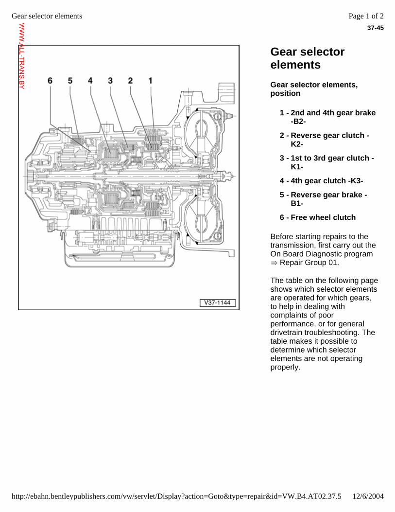
37-45
Gear selector elements Gear selector elements, position
Before starting repairs to the transmission, first carry out the On Board Diagnostic program
Repair Group 01.
The table on the following page shows which selector elements are operated for which gears, to help in dealing with complaints of poor performance, or for general drivetrain troubleshooting. The table makes it possible to determine which selector elements are not operating properly.
1 - 2nd and 4th gear brake -B2-
2 - Reverse gear clutch -K2-
3 - 1st to 3rd gear clutch -K1-
4 - 4th gear clutch -K3-
5 - Reverse gear brake -B1-
6 - Free wheel clutch
Page 1 of 2Gear selector elements
12/6/2004http://ebahn.bentleypublishers.com/vw/servlet/Display?action=Goto&type=repair&id=VW.B4.AT02.37.5
WWW.ALL-TR
ANS.BY
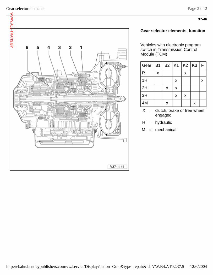
37-46
Gear selector elements, function
Vehicles with electronic program switch in Transmission Control Module (TCM)
Gear B1 B2 K1 K2 K3 F
R x x
1H x x
2H x x
3H x x
4M x x
X = clutch, brake or free wheel engaged
H = hydraulic
M = mechanical
Page 2 of 2Gear selector elements
12/6/2004http://ebahn.bentleypublishers.com/vw/servlet/Display?action=Goto&type=repair&id=VW.B4.AT02.37.5
WWW.ALL-TR
ANS.BY
37-47
Transmission, disassembling and assembling
ATF cooler and ATF filler tube, removing and installing page 37-48
Planetary gearbox disassembly and assembly, overview page 37-49
Planetary gearbox, disassembling page 37-61
Planetary gearbox, assembling page 37-67
Planetary gearbox adjustments, overview page 37-79
Valve body, removing and installing page 38-22
Page 1 of 60Transmission, disassembling and assembling
12/6/2004http://ebahn.bentleypublishers.com/vw/servlet/Display?action=Goto&type=repair&id=VW.B4.AT02.37.6
WWW.ALL-TR
ANS.BY
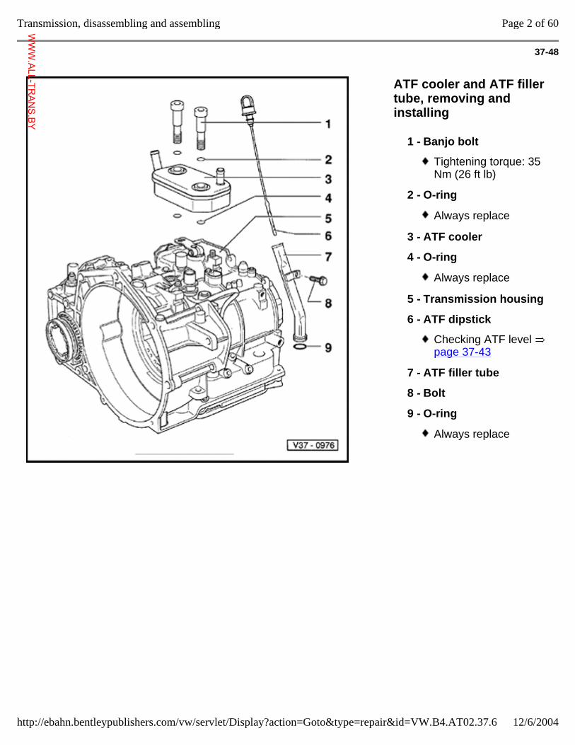
37-48
ATF cooler and ATF filler tube, removing and installing
1 - Banjo bolt
Tightening torque: 35 Nm (26 ft lb)
2 - O-ring
Always replace
3 - ATF cooler
4 - O-ring
Always replace
5 - Transmission housing
6 - ATF dipstick
Checking ATF level page 37-43
7 - ATF filler tube
8 - Bolt
9 - O-ring
Always replace
Page 2 of 60Transmission, disassembling and assembling
12/6/2004http://ebahn.bentleypublishers.com/vw/servlet/Display?action=Goto&type=repair&id=VW.B4.AT02.37.6
WWW.ALL-TR
ANS.BY
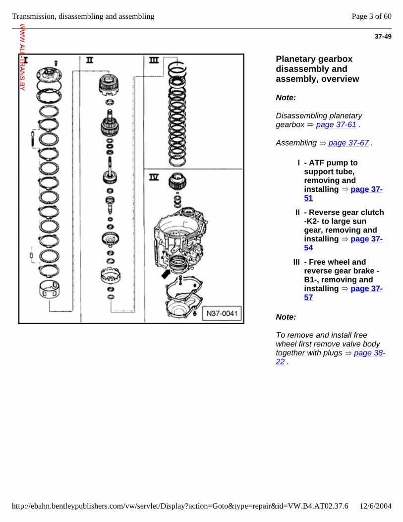
37-49
Planetary gearbox disassembly and assembly, overview
Note:
Disassembling planetary gearbox page 37-61 .
Assembling page 37-67 .
Note:
To remove and install free wheel first remove valve body together with plugs page 38-22 .
I - ATF pump to support tube, removing and installing page 37-51
II - Reverse gear clutch -K2- to large sun gear, removing and installing page 37-54
III - Free wheel and reverse gear brake -B1-, removing and installing page 37-57
Page 3 of 60Transmission, disassembling and assembling
12/6/2004http://ebahn.bentleypublishers.com/vw/servlet/Display?action=Goto&type=repair&id=VW.B4.AT02.37.6
WWW.ALL-TR
ANS.BY
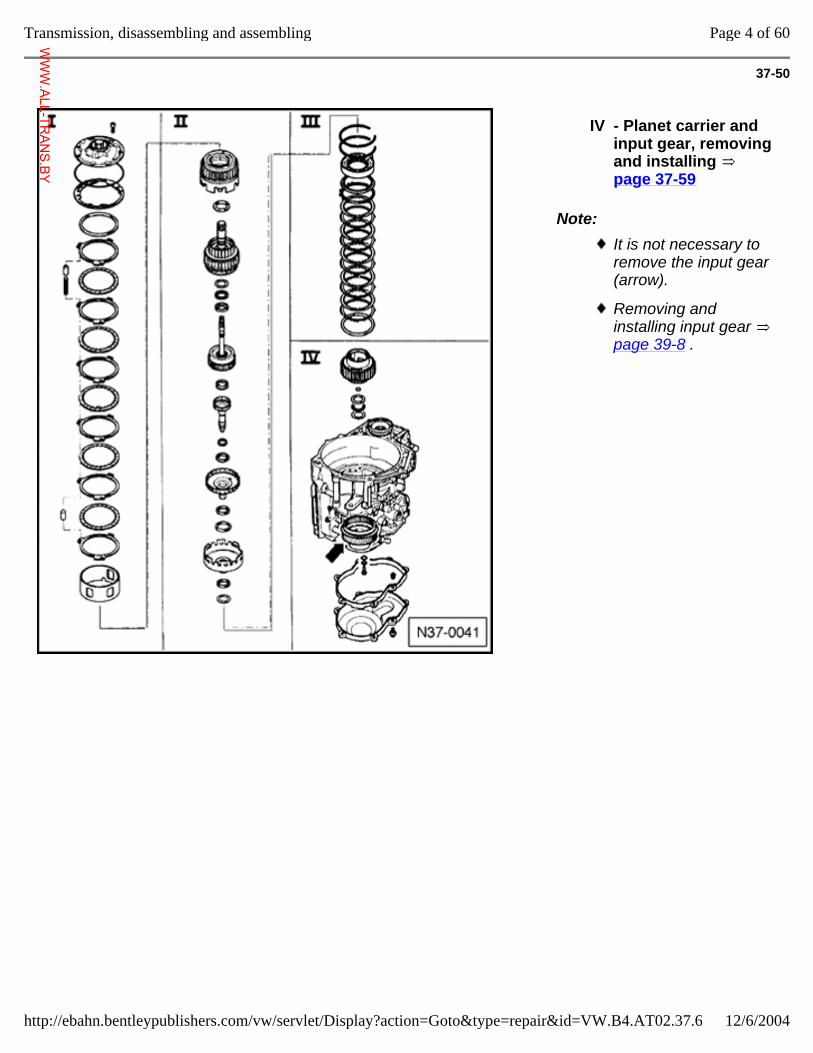
37-50
Note:
IV - Planet carrier and input gear, removing and installing page 37-59
It is not necessary to remove the input gear (arrow).
Removing and installing input gear page 39-8 .
Page 4 of 60Transmission, disassembling and assembling
12/6/2004http://ebahn.bentleypublishers.com/vw/servlet/Display?action=Goto&type=repair&id=VW.B4.AT02.37.6
WWW.ALL-TR
ANS.BY
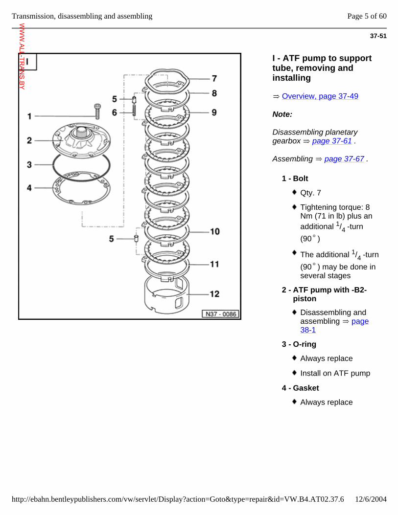
37-51
I - ATF pump to support tube, removing and installing
Overview, page 37-49
Note:
Disassembling planetary gearbox page 37-61 .
Assembling page 37-67 .
1 - Bolt
Qty. 7
Tightening torque: 8 Nm (71 in lb) plus an additional 1/4 -turn (90 )
The additional 1/4 -turn (90 ) may be done in several stages
2 - ATF pump with -B2- piston
Disassembling and assembling page 38-1
3 - O-ring
Always replace
Install on ATF pump
4 - Gasket
Always replace
Page 5 of 60Transmission, disassembling and assembling
12/6/2004http://ebahn.bentleypublishers.com/vw/servlet/Display?action=Goto&type=repair&id=VW.B4.AT02.37.6
WWW.ALL-TR
ANS.BY
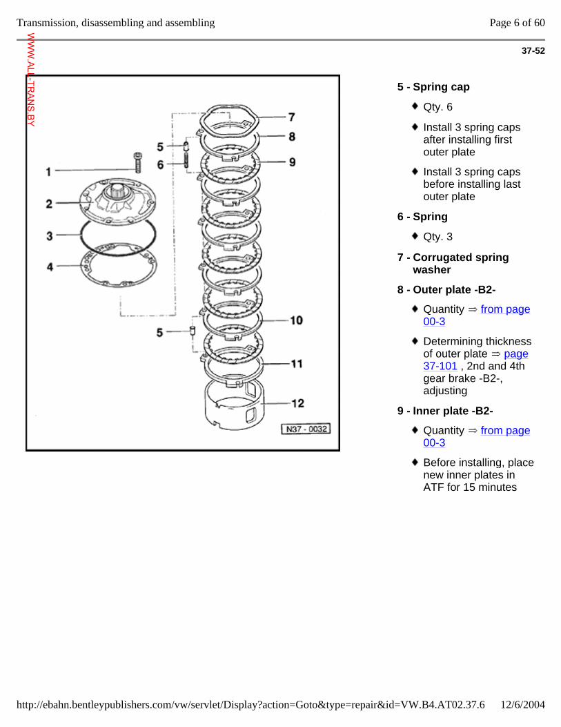
37-52
5 - Spring cap
Qty. 6
Install 3 spring caps after installing first outer plate
Install 3 spring caps before installing last outer plate
6 - Spring
Qty. 3
7 - Corrugated spring washer
8 - Outer plate -B2-
Quantity from page 00-3
Determining thickness of outer plate page 37-101 , 2nd and 4th gear brake -B2-, adjusting
9 - Inner plate -B2-
Quantity from page 00-3
Before installing, place new inner plates in ATF for 15 minutes
Page 6 of 60Transmission, disassembling and assembling
12/6/2004http://ebahn.bentleypublishers.com/vw/servlet/Display?action=Goto&type=repair&id=VW.B4.AT02.37.6
WWW.ALL-TR
ANS.BY
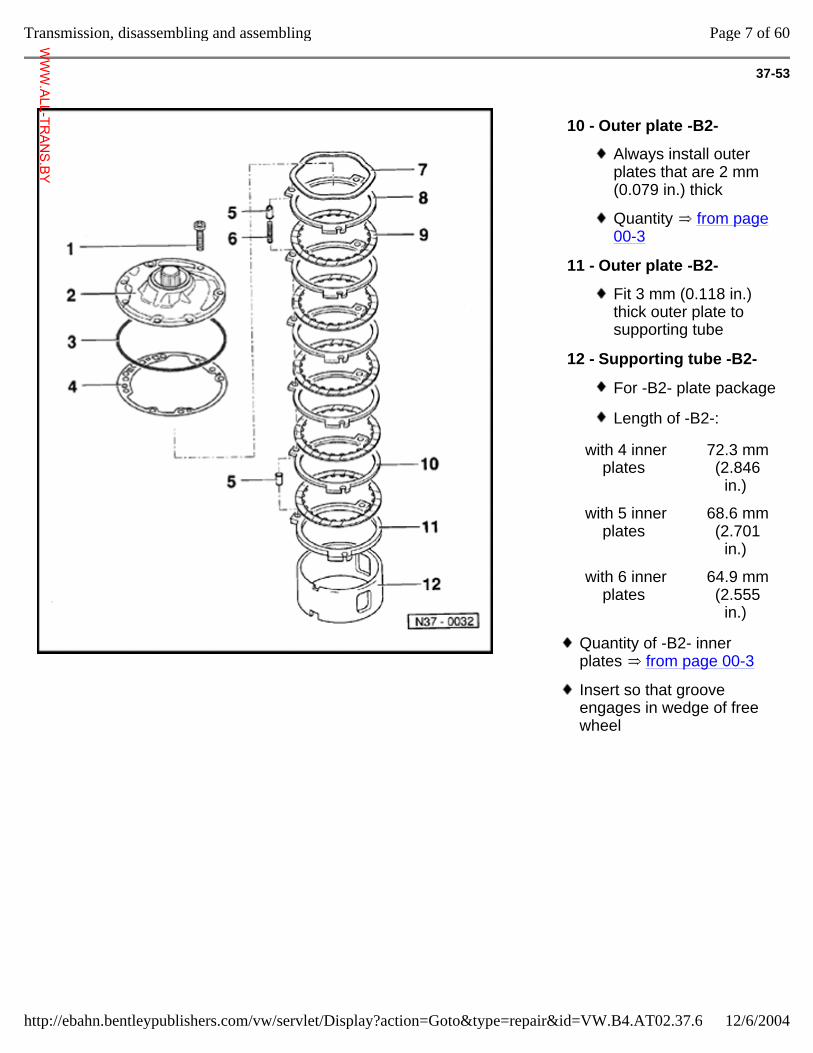
37-53
10 - Outer plate -B2-
Always install outer plates that are 2 mm (0.079 in.) thick
Quantity from page 00-3
11 - Outer plate -B2-
Fit 3 mm (0.118 in.) thick outer plate to supporting tube
12 - Supporting tube -B2-
For -B2- plate package
Length of -B2-:
with 4 inner plates
72.3 mm (2.846
in.)
with 5 inner plates
68.6 mm (2.701
in.)
with 6 inner plates
64.9 mm (2.555
in.)
Quantity of -B2- inner plates from page 00-3
Insert so that groove engages in wedge of free wheel
Page 7 of 60Transmission, disassembling and assembling
12/6/2004http://ebahn.bentleypublishers.com/vw/servlet/Display?action=Goto&type=repair&id=VW.B4.AT02.37.6
WWW.ALL-TR
ANS.BY
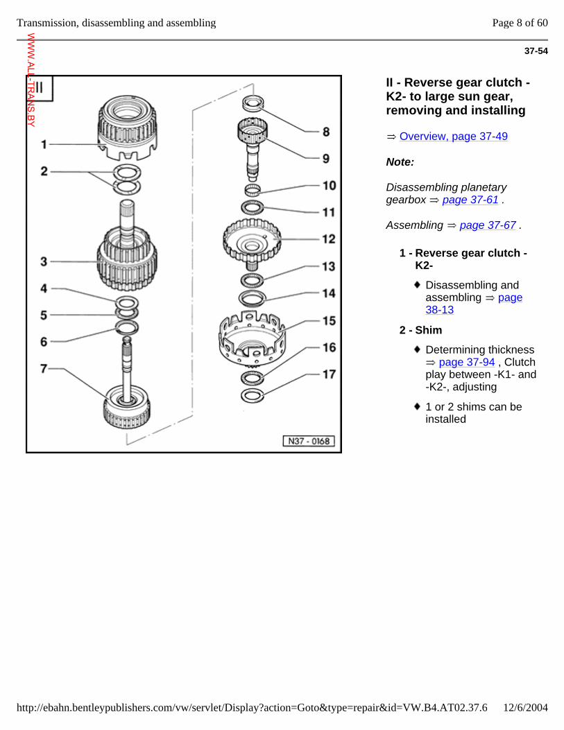
37-54
II - Reverse gear clutch -K2- to large sun gear, removing and installing
Overview, page 37-49
Note:
Disassembling planetary gearbox page 37-61 .
Assembling page 37-67 .
1 - Reverse gear clutch -K2-
Disassembling and assembling page 38-13
2 - Shim
Determining thickness page 37-94 , Clutch
play between -K1- and -K2-, adjusting
1 or 2 shims can be installed
Page 8 of 60Transmission, disassembling and assembling
12/6/2004http://ebahn.bentleypublishers.com/vw/servlet/Display?action=Goto&type=repair&id=VW.B4.AT02.37.6
WWW.ALL-TR
ANS.BY
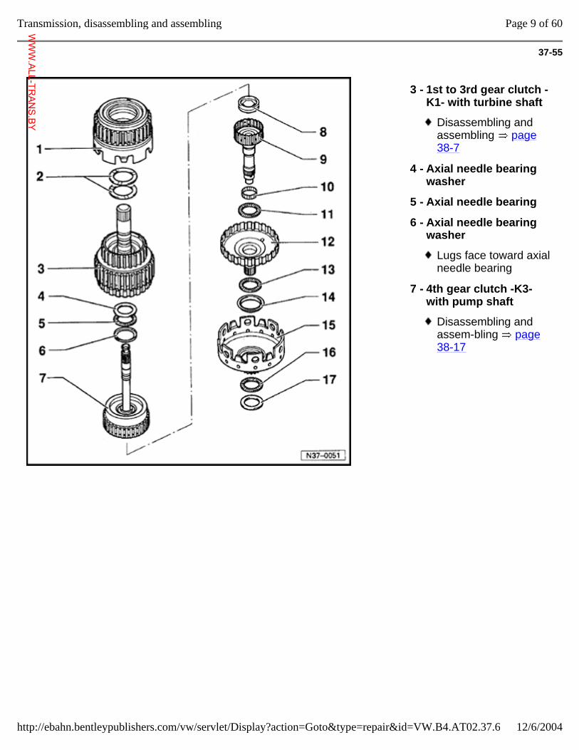
37-55
3 - 1st to 3rd gear clutch -K1- with turbine shaft
Disassembling and assembling page 38-7
4 - Axial needle bearing washer
5 - Axial needle bearing
6 - Axial needle bearing washer
Lugs face toward axial needle bearing
7 - 4th gear clutch -K3- with pump shaft
Disassembling and assem-bling page 38-17
Page 9 of 60Transmission, disassembling and assembling
12/6/2004http://ebahn.bentleypublishers.com/vw/servlet/Display?action=Goto&type=repair&id=VW.B4.AT02.37.6
WWW.ALL-TR
ANS.BY
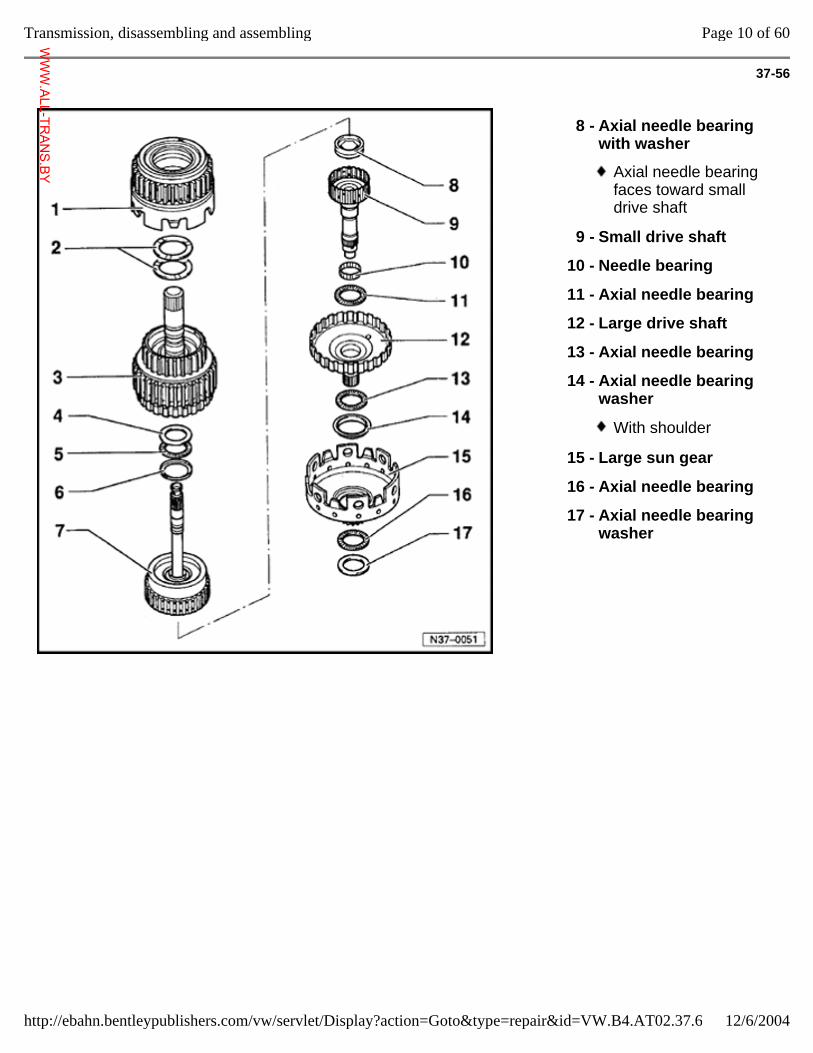
37-56
8 - Axial needle bearing with washer
Axial needle bearing faces toward small drive shaft
9 - Small drive shaft
10 - Needle bearing
11 - Axial needle bearing
12 - Large drive shaft
13 - Axial needle bearing
14 - Axial needle bearing washer
With shoulder
15 - Large sun gear
16 - Axial needle bearing
17 - Axial needle bearing washer
Page 10 of 60Transmission, disassembling and assembling
12/6/2004http://ebahn.bentleypublishers.com/vw/servlet/Display?action=Goto&type=repair&id=VW.B4.AT02.37.6
WWW.ALL-TR
ANS.BY
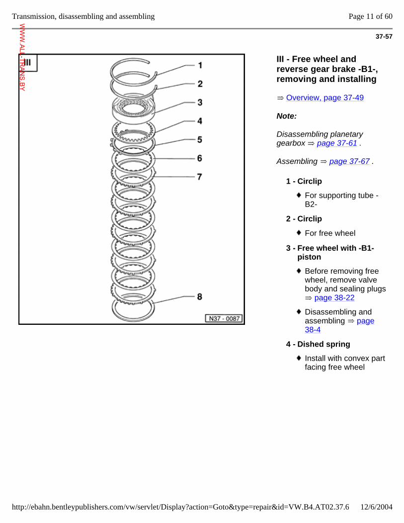
37-57
III - Free wheel and reverse gear brake -B1-, removing and installing
Overview, page 37-49
Note:
Disassembling planetary gearbox page 37-61 .
Assembling page 37-67 .
1 - Circlip
For supporting tube -B2-
2 - Circlip
For free wheel
3 - Free wheel with -B1- piston
Before removing free wheel, remove valve body and sealing plugs
page 38-22
Disassembling and assembling page 38-4
4 - Dished spring
Install with convex part facing free wheel
Page 11 of 60Transmission, disassembling and assembling
12/6/2004http://ebahn.bentleypublishers.com/vw/servlet/Display?action=Goto&type=repair&id=VW.B4.AT02.37.6
WWW.ALL-TR
ANS.BY
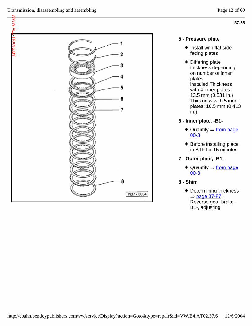
37-58
5 - Pressure plate
Install with flat side facing plates
Differing plate thickness depending on number of inner plates installed:Thickness with 4 inner plates: 13.5 mm (0.531 in.)Thickness with 5 inner plates: 10.5 mm (0.413 in.)
6 - Inner plate, -B1-
Quantity from page 00-3
Before installing place in ATF for 15 minutes
7 - Outer plate, -B1-
Quantity from page 00-3
8 - Shim
Determining thickness page 37-87 ,
Reverse gear brake -B1-, adjusting
Page 12 of 60Transmission, disassembling and assembling
12/6/2004http://ebahn.bentleypublishers.com/vw/servlet/Display?action=Goto&type=repair&id=VW.B4.AT02.37.6
WWW.ALL-TR
ANS.BY
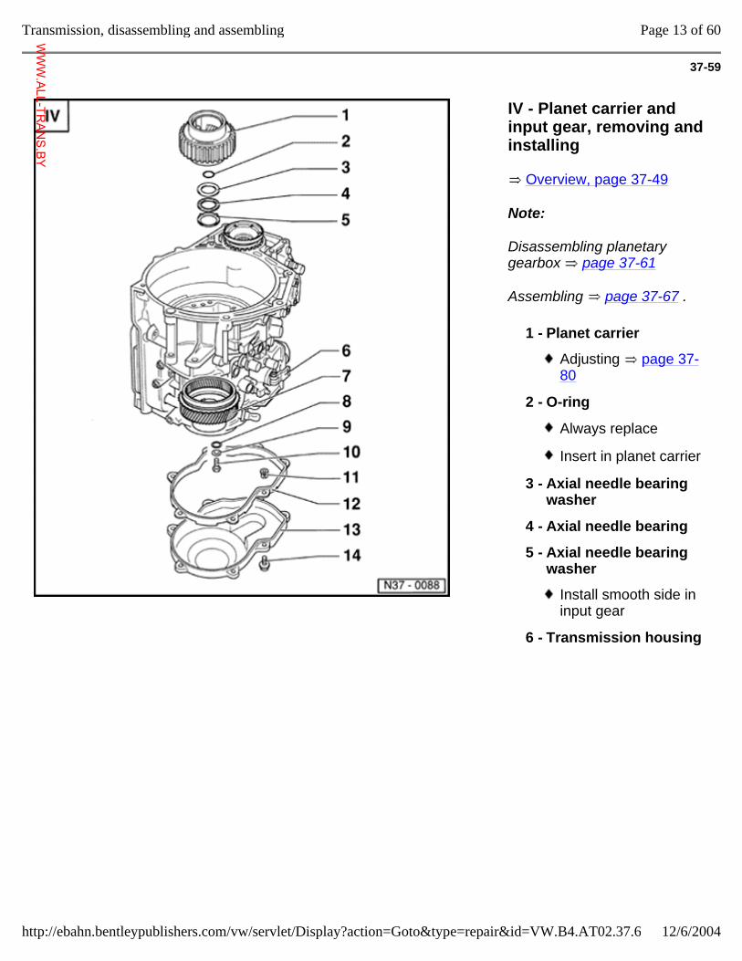
37-59
IV - Planet carrier and input gear, removing and installing
Overview, page 37-49
Note:
Disassembling planetary gearbox page 37-61
Assembling page 37-67 .
1 - Planet carrier
Adjusting page 37-80
2 - O-ring
Always replace
Insert in planet carrier
3 - Axial needle bearing washer
4 - Axial needle bearing
5 - Axial needle bearing washer
Install smooth side in input gear
6 - Transmission housing
Page 13 of 60Transmission, disassembling and assembling
12/6/2004http://ebahn.bentleypublishers.com/vw/servlet/Display?action=Goto&type=repair&id=VW.B4.AT02.37.6
WWW.ALL-TR
ANS.BY
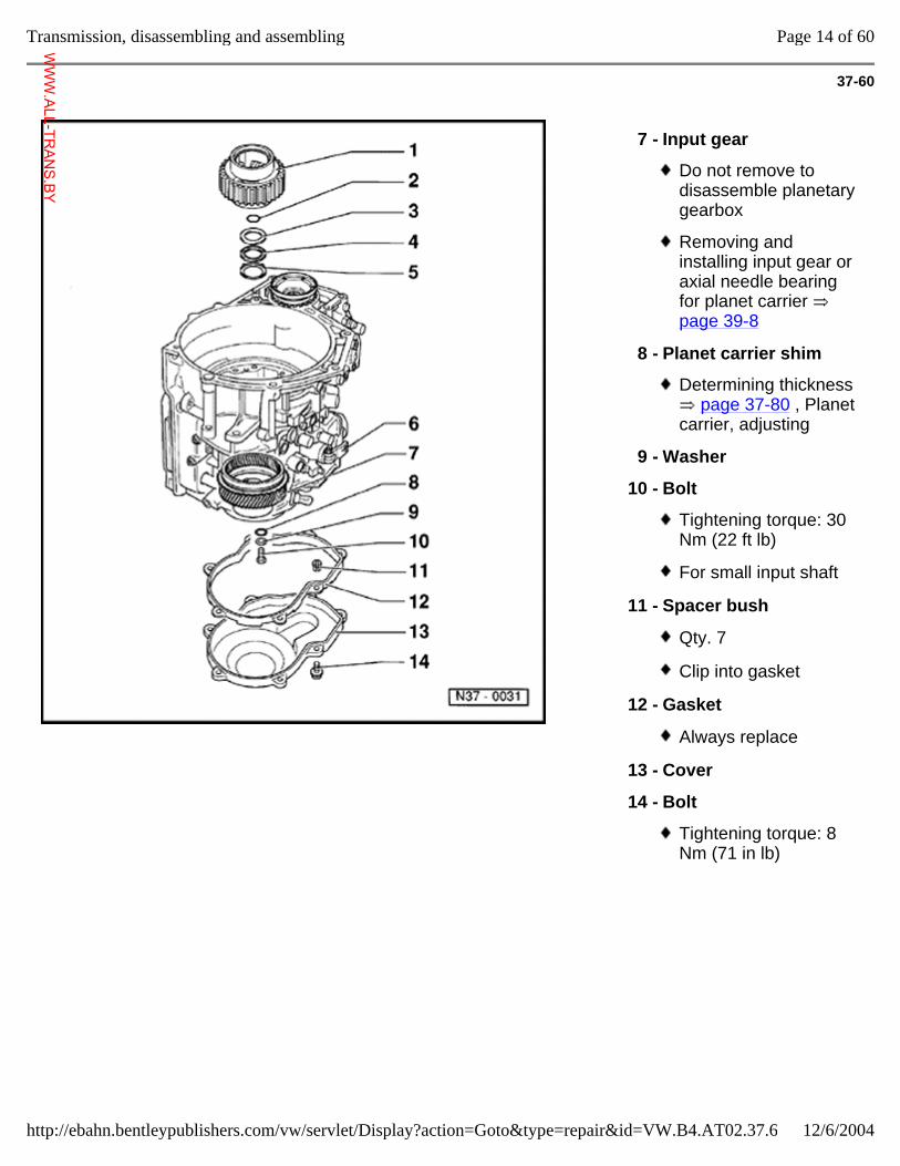
37-60
7 - Input gear
Do not remove to disassemble planetary gearbox
Removing and installing input gear or axial needle bearing for planet carrier page 39-8
8 - Planet carrier shim
Determining thickness page 37-80 , Planet
carrier, adjusting
9 - Washer
10 - Bolt
Tightening torque: 30 Nm (22 ft lb)
For small input shaft
11 - Spacer bush
Qty. 7
Clip into gasket
12 - Gasket
Always replace
13 - Cover
14 - Bolt
Tightening torque: 8 Nm (71 in lb)
Page 14 of 60Transmission, disassembling and assembling
12/6/2004http://ebahn.bentleypublishers.com/vw/servlet/Display?action=Goto&type=repair&id=VW.B4.AT02.37.6
WWW.ALL-TR
ANS.BY
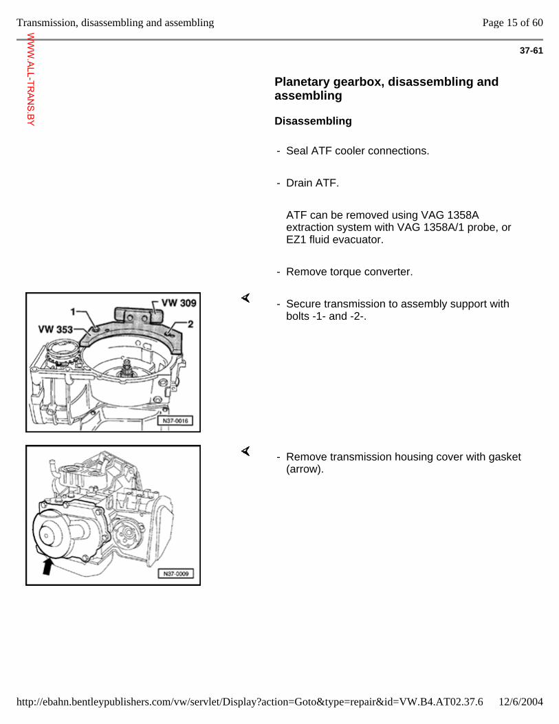
37-61
Planetary gearbox, disassembling and assembling
Disassembling
- Seal ATF cooler connections.
- Drain ATF.
ATF can be removed using VAG 1358A extraction system with VAG 1358A/1 probe, or EZ1 fluid evacuator.
- Remove torque converter.
- Secure transmission to assembly support with bolts -1- and -2-.
- Remove transmission housing cover with gasket (arrow).
Page 15 of 60Transmission, disassembling and assembling
12/6/2004http://ebahn.bentleypublishers.com/vw/servlet/Display?action=Goto&type=repair&id=VW.B4.AT02.37.6
WWW.ALL-TR
ANS.BY
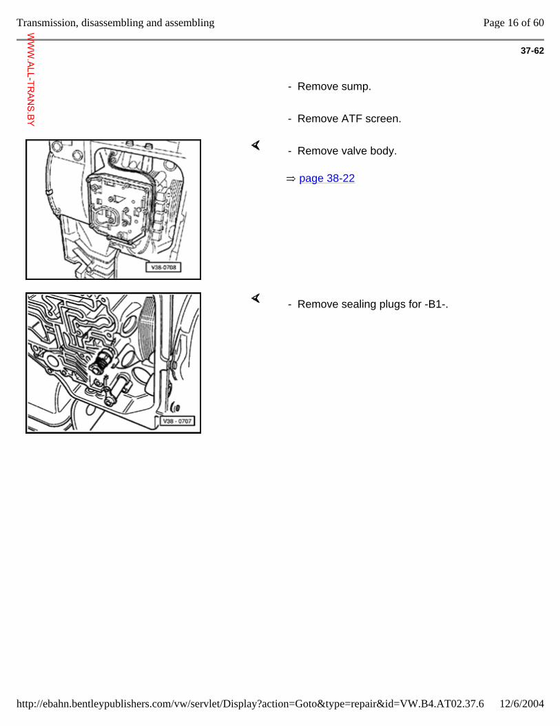
37-62
- Remove sump.
- Remove ATF screen.
page 38-22
- Remove valve body.
- Remove sealing plugs for -B1-.
Page 16 of 60Transmission, disassembling and assembling
12/6/2004http://ebahn.bentleypublishers.com/vw/servlet/Display?action=Goto&type=repair&id=VW.B4.AT02.37.6
WWW.ALL-TR
ANS.BY
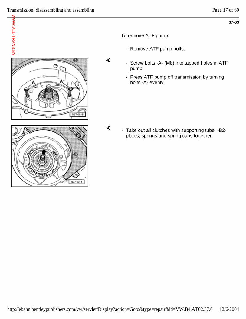
37-63
To remove ATF pump:
- Remove ATF pump bolts.
- Screw bolts -A- (M8) into tapped holes in ATF pump.
- Press ATF pump off transmission by turning bolts -A- evenly.
- Take out all clutches with supporting tube, -B2- plates, springs and spring caps together.
Page 17 of 60Transmission, disassembling and assembling
12/6/2004http://ebahn.bentleypublishers.com/vw/servlet/Display?action=Goto&type=repair&id=VW.B4.AT02.37.6
WWW.ALL-TR
ANS.BY
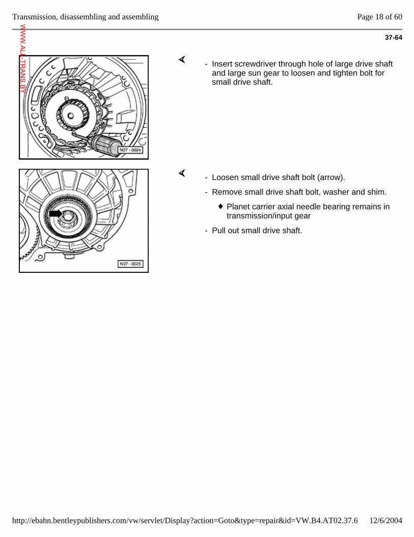
37-64
- Insert screwdriver through hole of large drive shaft and large sun gear to loosen and tighten bolt for small drive shaft.
- Loosen small drive shaft bolt (arrow).
- Remove small drive shaft bolt, washer and shim.
Planet carrier axial needle bearing remains in transmission/input gear
- Pull out small drive shaft.
Page 18 of 60Transmission, disassembling and assembling
12/6/2004http://ebahn.bentleypublishers.com/vw/servlet/Display?action=Goto&type=repair&id=VW.B4.AT02.37.6
WWW.ALL-TR
ANS.BY
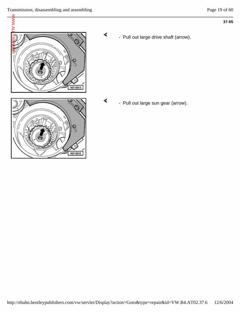
37-65
- Pull out large drive shaft (arrow).
- Pull out large sun gear (arrow).
Page 19 of 60Transmission, disassembling and assembling
12/6/2004http://ebahn.bentleypublishers.com/vw/servlet/Display?action=Goto&type=repair&id=VW.B4.AT02.37.6
WWW.ALL-TR
ANS.BY
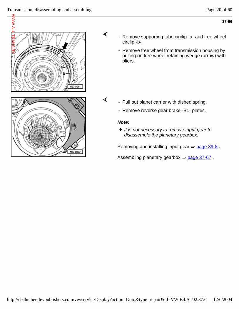
37-66
- Remove supporting tube circlip -a- and free wheel circlip -b-.
- Remove free wheel from transmission housing by pulling on free wheel retaining wedge (arrow) with pliers.
Note:
Removing and installing input gear page 39-8 .
Assembling planetary gearbox page 37-67 .
- Pull out planet carrier with dished spring.
- Remove reverse gear brake -B1- plates.
It is not necessary to remove input gear to disassemble the planetary gearbox.
Page 20 of 60Transmission, disassembling and assembling
12/6/2004http://ebahn.bentleypublishers.com/vw/servlet/Display?action=Goto&type=repair&id=VW.B4.AT02.37.6
WWW.ALL-TR
ANS.BY
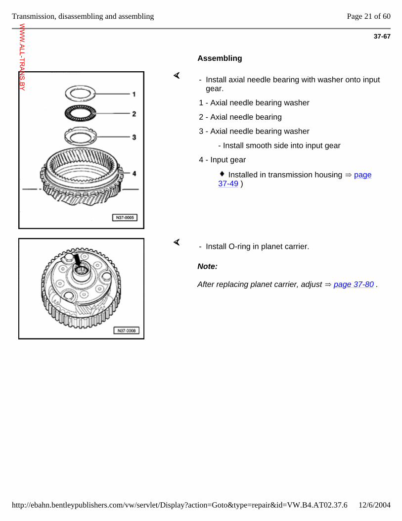
37-67
Assembling
- Install axial needle bearing with washer onto input gear.
1 - Axial needle bearing washer
2 - Axial needle bearing
3 - Axial needle bearing washer
- Install smooth side into input gear
4 - Input gear
Installed in transmission housing page 37-49 )
Note:
After replacing planet carrier, adjust page 37-80 .
- Install O-ring in planet carrier.
Page 21 of 60Transmission, disassembling and assembling
12/6/2004http://ebahn.bentleypublishers.com/vw/servlet/Display?action=Goto&type=repair&id=VW.B4.AT02.37.6
WWW.ALL-TR
ANS.BY
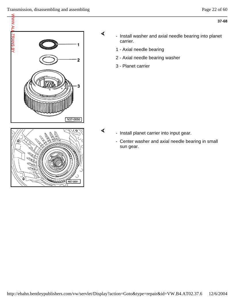
37-68
- Install washer and axial needle bearing into planet carrier.
1 - Axial needle bearing
2 - Axial needle bearing washer
3 - Planet carrier
- Install planet carrier into input gear.
- Center washer and axial needle bearing in small sun gear.
Page 22 of 60Transmission, disassembling and assembling
12/6/2004http://ebahn.bentleypublishers.com/vw/servlet/Display?action=Goto&type=repair&id=VW.B4.AT02.37.6
WWW.ALL-TR
ANS.BY
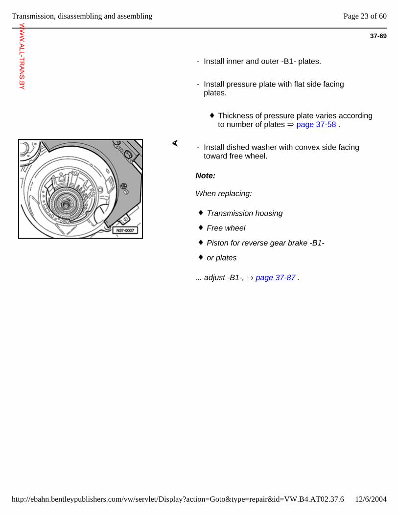
37-69
- Install inner and outer -B1- plates.
- Install pressure plate with flat side facing plates.
Thickness of pressure plate varies according to number of plates page 37-58 .
Note:
When replacing:
... adjust -B1-, page 37-87 .
- Install dished washer with convex side facing toward free wheel.
Transmission housing
Free wheel
Piston for reverse gear brake -B1-
or plates
Page 23 of 60Transmission, disassembling and assembling
12/6/2004http://ebahn.bentleypublishers.com/vw/servlet/Display?action=Goto&type=repair&id=VW.B4.AT02.37.6
WWW.ALL-TR
ANS.BY
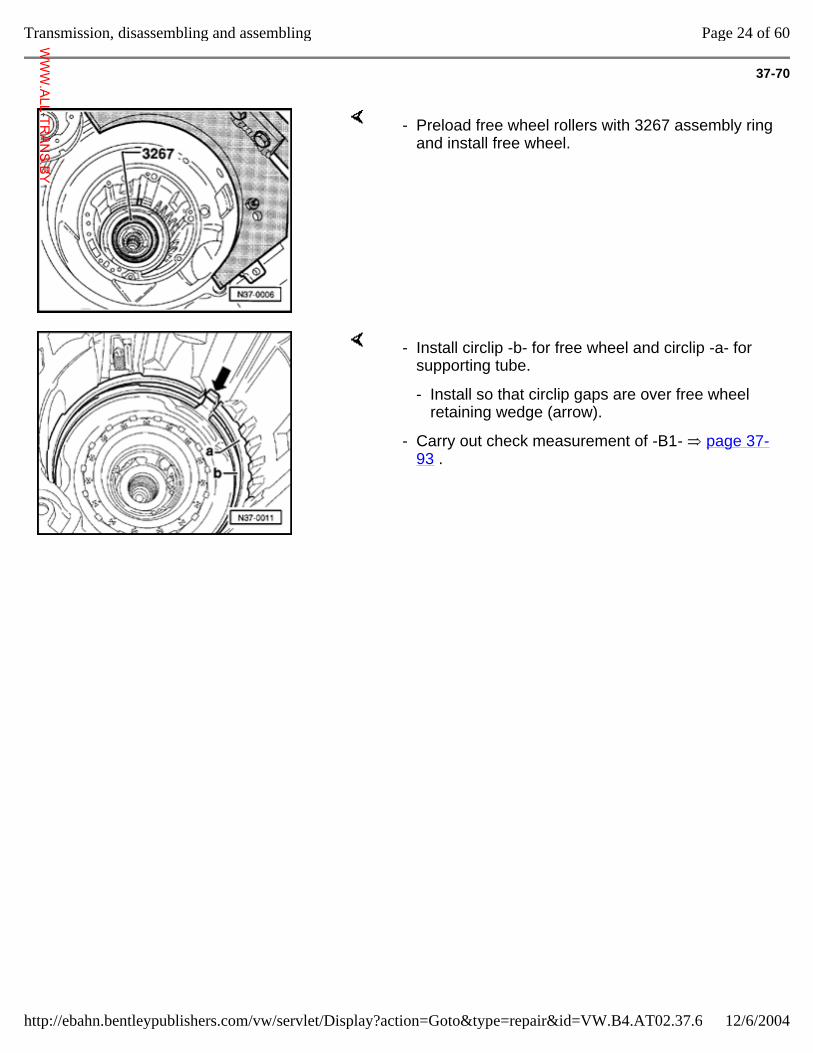
37-70
- Preload free wheel rollers with 3267 assembly ring and install free wheel.
- Install circlip -b- for free wheel and circlip -a- for supporting tube.
- Install so that circlip gaps are over free wheel retaining wedge (arrow).
- Carry out check measurement of -B1- page 37-93 .
Page 24 of 60Transmission, disassembling and assembling
12/6/2004http://ebahn.bentleypublishers.com/vw/servlet/Display?action=Goto&type=repair&id=VW.B4.AT02.37.6
WWW.ALL-TR
ANS.BY
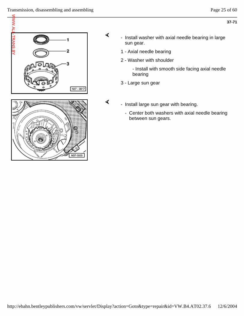
37-71
- Install washer with axial needle bearing in large sun gear.
1 - Axial needle bearing
2 - Washer with shoulder
- Install with smooth side facing axial needle bearing
3 - Large sun gear
- Install large sun gear with bearing.
- Center both washers with axial needle bearing between sun gears.
Page 25 of 60Transmission, disassembling and assembling
12/6/2004http://ebahn.bentleypublishers.com/vw/servlet/Display?action=Goto&type=repair&id=VW.B4.AT02.37.6
WWW.ALL-TR
ANS.BY
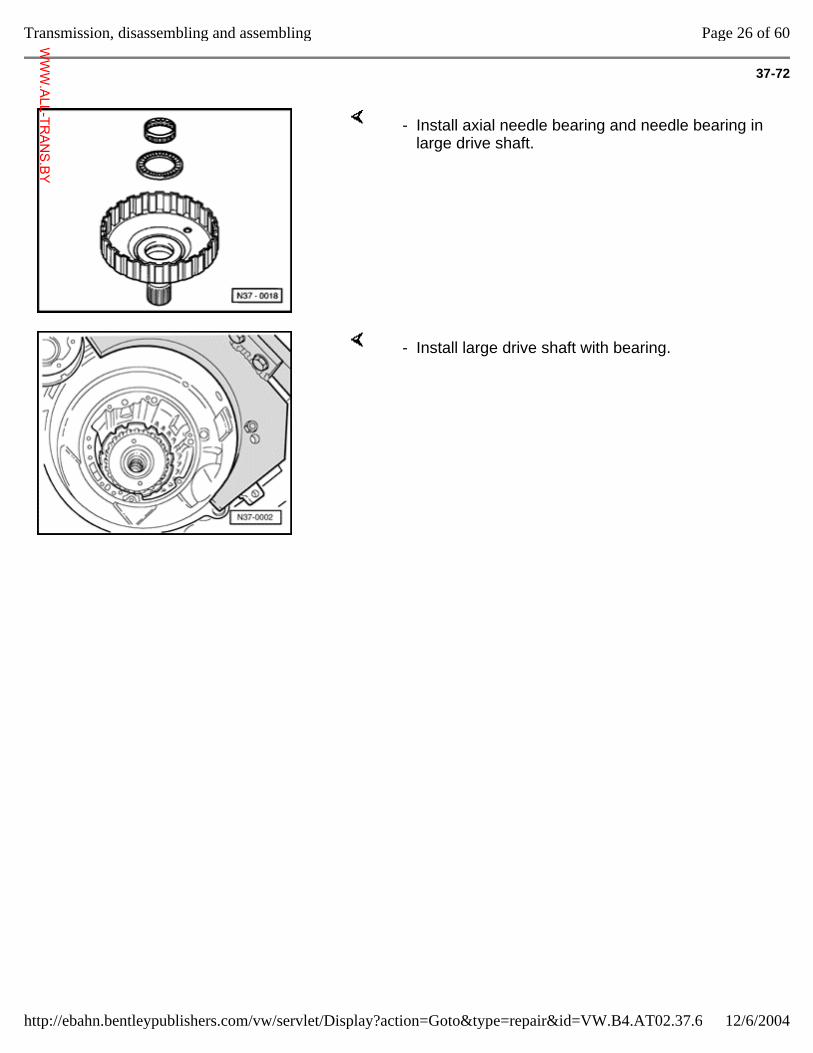
37-72
- Install axial needle bearing and needle bearing in large drive shaft.
- Install large drive shaft with bearing.
Page 26 of 60Transmission, disassembling and assembling
12/6/2004http://ebahn.bentleypublishers.com/vw/servlet/Display?action=Goto&type=repair&id=VW.B4.AT02.37.6
WWW.ALL-TR
ANS.BY
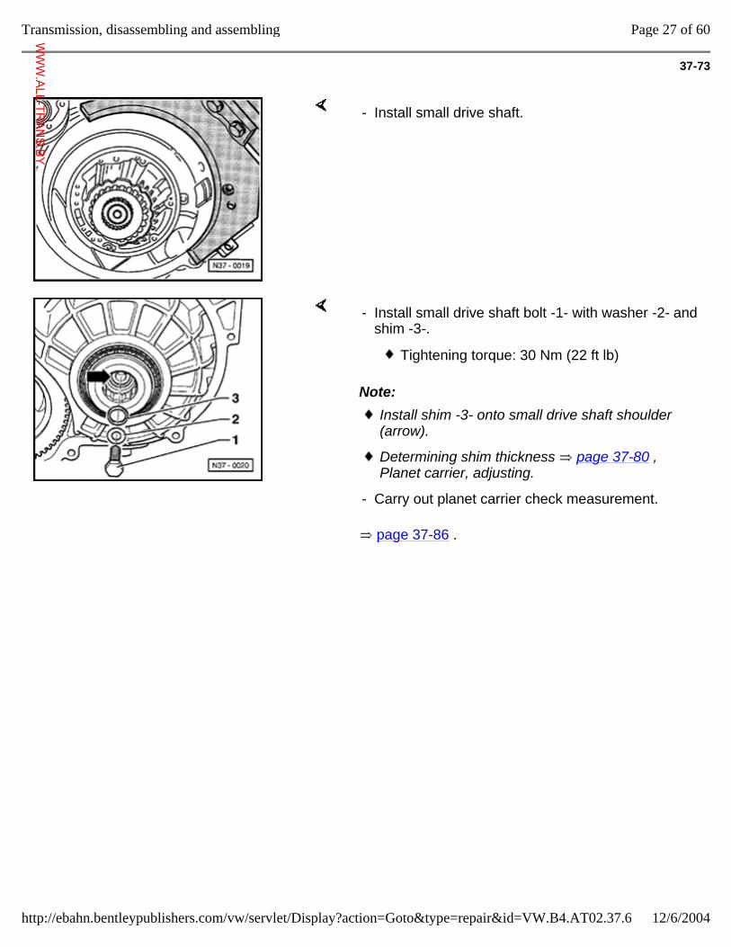
37-73
- Install small drive shaft.
Note:
page 37-86 .
- Install small drive shaft bolt -1- with washer -2- and shim -3-.
Tightening torque: 30 Nm (22 ft lb)
Install shim -3- onto small drive shaft shoulder (arrow).
Determining shim thickness page 37-80 , Planet carrier, adjusting.
- Carry out planet carrier check measurement.
Page 27 of 60Transmission, disassembling and assembling
12/6/2004http://ebahn.bentleypublishers.com/vw/servlet/Display?action=Goto&type=repair&id=VW.B4.AT02.37.6
WWW.ALL-TR
ANS.BY
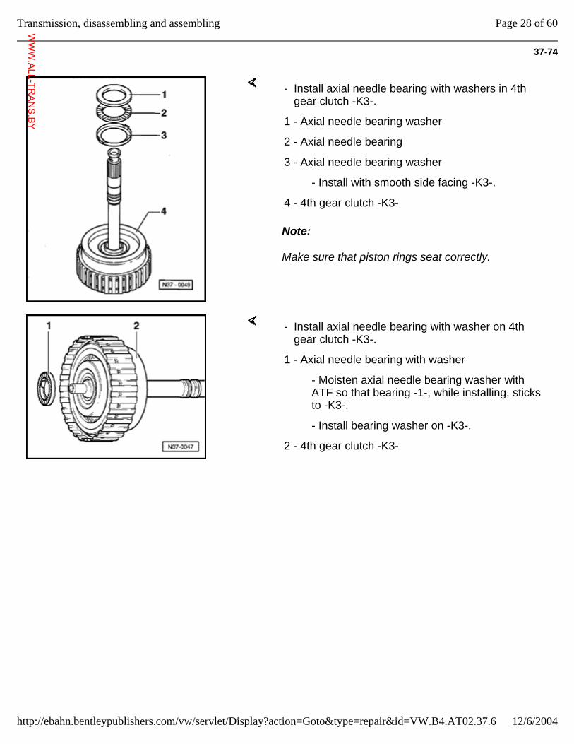
37-74
Note:
Make sure that piston rings seat correctly.
- Install axial needle bearing with washers in 4th gear clutch -K3-.
1 - Axial needle bearing washer
2 - Axial needle bearing
3 - Axial needle bearing washer
- Install with smooth side facing -K3-.
4 - 4th gear clutch -K3-
- Install axial needle bearing with washer on 4th gear clutch -K3-.
1 - Axial needle bearing with washer
- Moisten axial needle bearing washer with ATF so that bearing -1-, while installing, sticks to -K3-.
- Install bearing washer on -K3-.
2 - 4th gear clutch -K3-
Page 28 of 60Transmission, disassembling and assembling
12/6/2004http://ebahn.bentleypublishers.com/vw/servlet/Display?action=Goto&type=repair&id=VW.B4.AT02.37.6
WWW.ALL-TR
ANS.BY
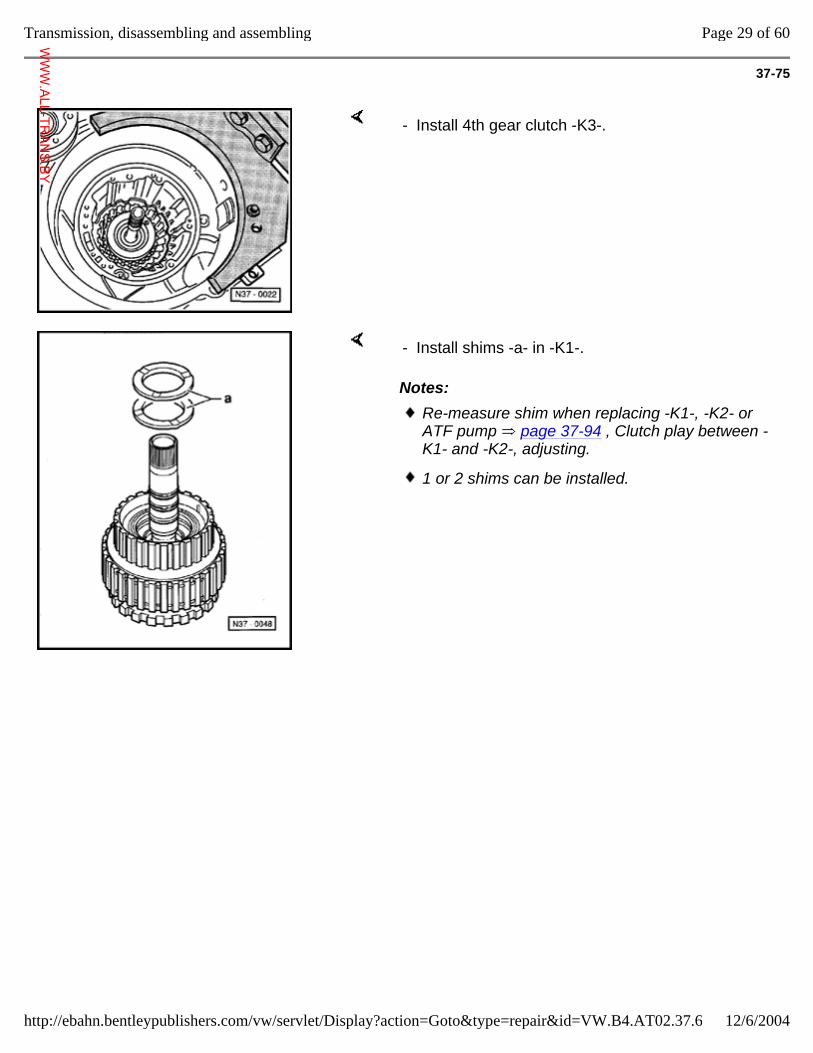
37-75
- Install 4th gear clutch -K3-.
Notes:
- Install shims -a- in -K1-.
Re-measure shim when replacing -K1-, -K2- or ATF pump page 37-94 , Clutch play between -K1- and -K2-, adjusting.
1 or 2 shims can be installed.
Page 29 of 60Transmission, disassembling and assembling
12/6/2004http://ebahn.bentleypublishers.com/vw/servlet/Display?action=Goto&type=repair&id=VW.B4.AT02.37.6
WWW.ALL-TR
ANS.BY
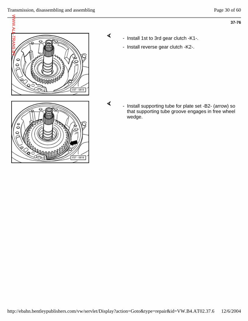
37-76
- Install 1st to 3rd gear clutch -K1-.
- Install reverse gear clutch -K2-.
- Install supporting tube for plate set -B2- (arrow) so that supporting tube groove engages in free wheel wedge.
Page 30 of 60Transmission, disassembling and assembling
12/6/2004http://ebahn.bentleypublishers.com/vw/servlet/Display?action=Goto&type=repair&id=VW.B4.AT02.37.6
WWW.ALL-TR
ANS.BY
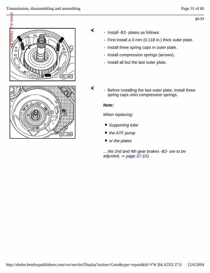
37-77
- Install -B2- plates as follows:
- First install a 3 mm (0.118 in.) thick outer plate.
- Install three spring caps in outer plate.
- Install compression springs (arrows).
- Install all but the last outer plate.
Note:
When replacing:
... the 2nd and 4th gear brakes -B2- are to be adjusted, page 37-101 .
- Before installing the last outer plate, install three spring caps onto compression springs.
Supporting tube
the ATF pump
or the plates
Page 31 of 60Transmission, disassembling and assembling
12/6/2004http://ebahn.bentleypublishers.com/vw/servlet/Display?action=Goto&type=repair&id=VW.B4.AT02.37.6
WWW.ALL-TR
ANS.BY
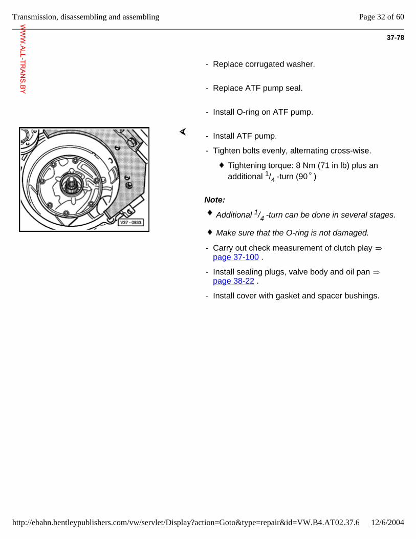
37-78
- Replace corrugated washer.
- Replace ATF pump seal.
- Install O-ring on ATF pump.
Note:
- Install ATF pump.
- Tighten bolts evenly, alternating cross-wise.
Tightening torque: 8 Nm (71 in lb) plus an additional 1/4 -turn (90 )
Additional 1/4 -turn can be done in several stages.
Make sure that the O-ring is not damaged.
- Carry out check measurement of clutch play page 37-100 .
- Install sealing plugs, valve body and oil pan page 38-22 .
- Install cover with gasket and spacer bushings.
Page 32 of 60Transmission, disassembling and assembling
12/6/2004http://ebahn.bentleypublishers.com/vw/servlet/Display?action=Goto&type=repair&id=VW.B4.AT02.37.6
WWW.ALL-TR
ANS.BY
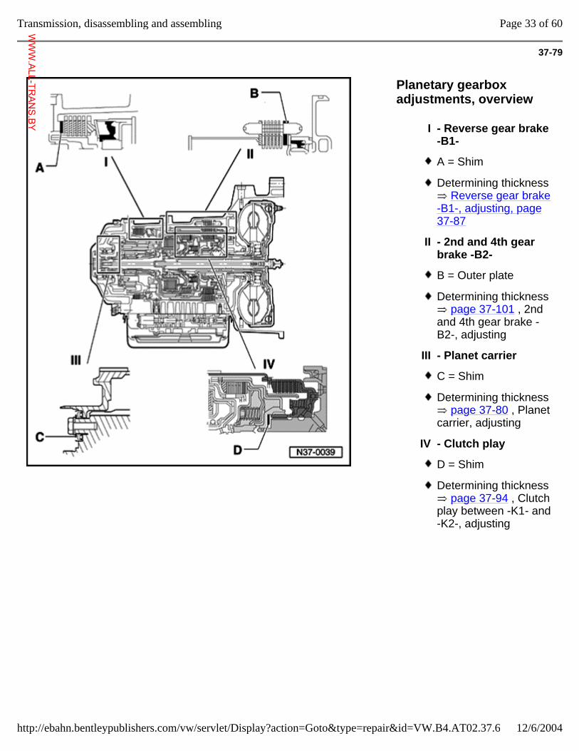
37-79
Planetary gearbox adjustments, overview
I - Reverse gear brake -B1-
A = Shim
Determining thickness Reverse gear brake
-B1-, adjusting, page 37-87
II - 2nd and 4th gear brake -B2-
B = Outer plate
Determining thickness page 37-101 , 2nd
and 4th gear brake -B2-, adjusting
III - Planet carrier
C = Shim
Determining thickness page 37-80 , Planet
carrier, adjusting
IV - Clutch play
D = Shim
Determining thickness page 37-94 , Clutch
play between -K1- and -K2-, adjusting
Page 33 of 60Transmission, disassembling and assembling
12/6/2004http://ebahn.bentleypublishers.com/vw/servlet/Display?action=Goto&type=repair&id=VW.B4.AT02.37.6
WWW.ALL-TR
ANS.BY
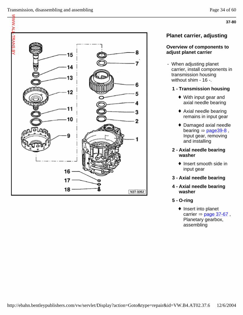
37-80
Planet carrier, adjusting
Overview of components to adjust planet carrier
- When adjusting planet carrier, install components in transmission housing without shim - 16 -.
1 - Transmission housing
With input gear and axial needle bearing
Axial needle bearing remains in input gear
Damaged axial needle bearing page39-8 , Input gear, removing and installing
2 - Axial needle bearing washer
Insert smooth side in input gear
3 - Axial needle bearing
4 - Axial needle bearing washer
5 - O-ring
Insert into planet carrier page 37-67 , Planetary gearbox, assembling
Page 34 of 60Transmission, disassembling and assembling
12/6/2004http://ebahn.bentleypublishers.com/vw/servlet/Display?action=Goto&type=repair&id=VW.B4.AT02.37.6
WWW.ALL-TR
ANS.BY
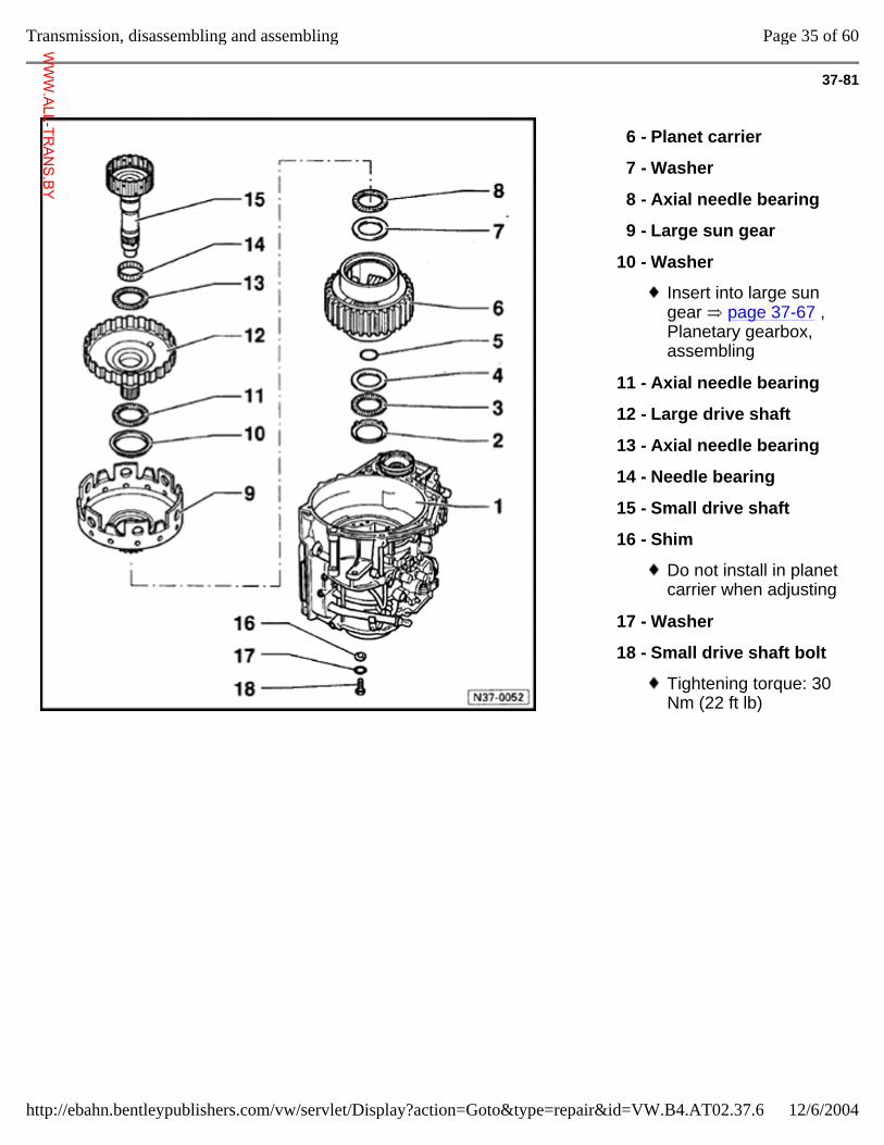
37-81
6 - Planet carrier
7 - Washer
8 - Axial needle bearing
9 - Large sun gear
10 - Washer
Insert into large sun gear page 37-67 , Planetary gearbox, assembling
11 - Axial needle bearing
12 - Large drive shaft
13 - Axial needle bearing
14 - Needle bearing
15 - Small drive shaft
16 - Shim
Do not install in planet carrier when adjusting
17 - Washer
18 - Small drive shaft bolt
Tightening torque: 30 Nm (22 ft lb)
Page 35 of 60Transmission, disassembling and assembling
12/6/2004http://ebahn.bentleypublishers.com/vw/servlet/Display?action=Goto&type=repair&id=VW.B4.AT02.37.6
WWW.ALL-TR
ANS.BY
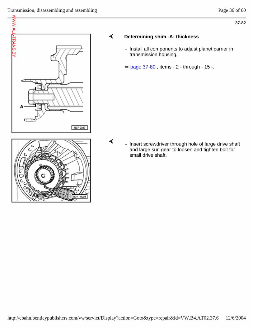
37-82
Determining shim -A- thickness
page 37-80 , items - 2 - through - 15 -.
- Install all components to adjust planet carrier in transmission housing.
- Insert screwdriver through hole of large drive shaft and large sun gear to loosen and tighten bolt for small drive shaft.
Page 36 of 60Transmission, disassembling and assembling
12/6/2004http://ebahn.bentleypublishers.com/vw/servlet/Display?action=Goto&type=repair&id=VW.B4.AT02.37.6
WWW.ALL-TR
ANS.BY
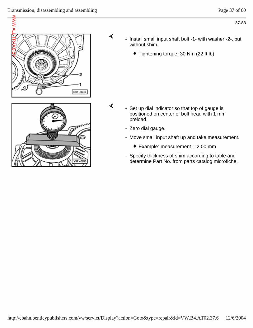
37-83
- Install small input shaft bolt -1- with washer -2-, but without shim.
Tightening torque: 30 Nm (22 ft lb)
- Set up dial indicator so that top of gauge is positioned on center of bolt head with 1 mm preload.
- Zero dial gauge.
- Move small input shaft up and take measurement.
Example: measurement = 2.00 mm
- Specify thickness of shim according to table and determine Part No. from parts catalog microfiche.
Page 37 of 60Transmission, disassembling and assembling
12/6/2004http://ebahn.bentleypublishers.com/vw/servlet/Display?action=Goto&type=repair&id=VW.B4.AT02.37.6
WWW.ALL-TR
ANS.BY
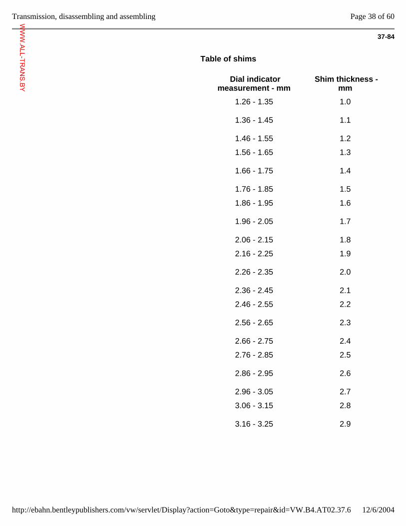
37-84
Table of shims
Dial indicator measurement - mm
Shim thickness - mm
1.26 - 1.35
1.36 - 1.45
1.46 - 1.55
1.0
1.1
1.2
1.56 - 1.65
1.66 - 1.75
1.76 - 1.85
1.3
1.4
1.5
1.86 - 1.95
1.96 - 2.05
2.06 - 2.15
1.6
1.7
1.8
2.16 - 2.25
2.26 - 2.35
2.36 - 2.45
1.9
2.0
2.1
2.46 - 2.55
2.56 - 2.65
2.66 - 2.75
2.2
2.3
2.4
2.76 - 2.85
2.86 - 2.95
2.96 - 3.05
2.5
2.6
2.7
3.06 - 3.15
3.16 - 3.25
2.8
2.9
Page 38 of 60Transmission, disassembling and assembling
12/6/2004http://ebahn.bentleypublishers.com/vw/servlet/Display?action=Goto&type=repair&id=VW.B4.AT02.37.6
WWW.ALL-TR
ANS.BY
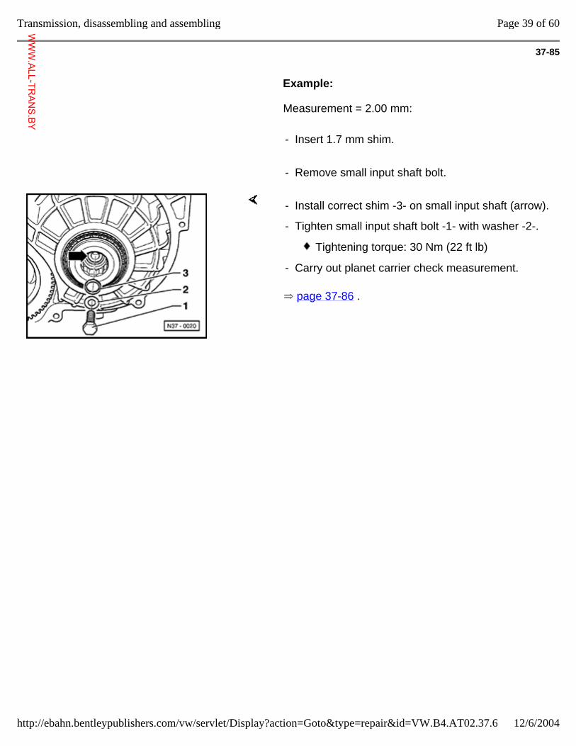
37-85
Example:
Measurement = 2.00 mm:
- Insert 1.7 mm shim.
- Remove small input shaft bolt.
page 37-86 .
- Install correct shim -3- on small input shaft (arrow).
- Tighten small input shaft bolt -1- with washer -2-.
Tightening torque: 30 Nm (22 ft lb)
- Carry out planet carrier check measurement.
Page 39 of 60Transmission, disassembling and assembling
12/6/2004http://ebahn.bentleypublishers.com/vw/servlet/Display?action=Goto&type=repair&id=VW.B4.AT02.37.6
WWW.ALL-TR
ANS.BY
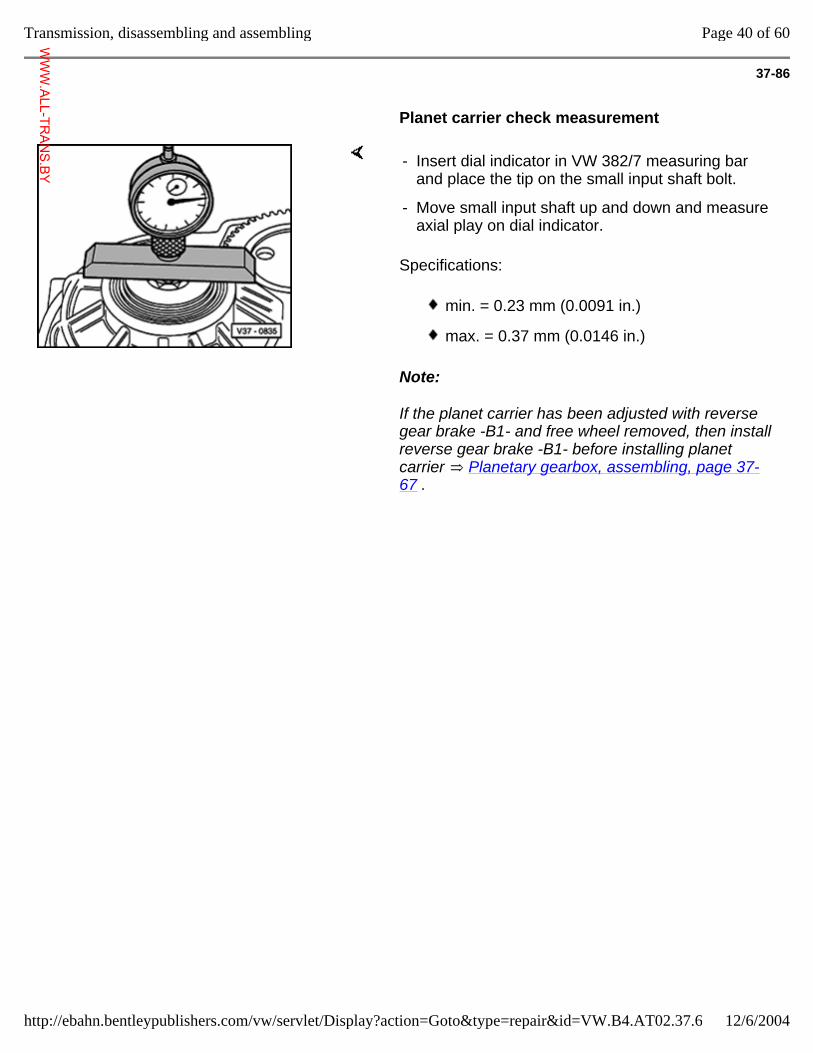
37-86
Planet carrier check measurement
Specifications:
Note:
If the planet carrier has been adjusted with reverse gear brake -B1- and free wheel removed, then install reverse gear brake -B1- before installing planet carrier Planetary gearbox, assembling, page 37-67 .
- Insert dial indicator in VW 382/7 measuring bar and place the tip on the small input shaft bolt.
- Move small input shaft up and down and measure axial play on dial indicator.
min. = 0.23 mm (0.0091 in.)
max. = 0.37 mm (0.0146 in.)
Page 40 of 60Transmission, disassembling and assembling
12/6/2004http://ebahn.bentleypublishers.com/vw/servlet/Display?action=Goto&type=repair&id=VW.B4.AT02.37.6
WWW.ALL-TR
ANS.BY
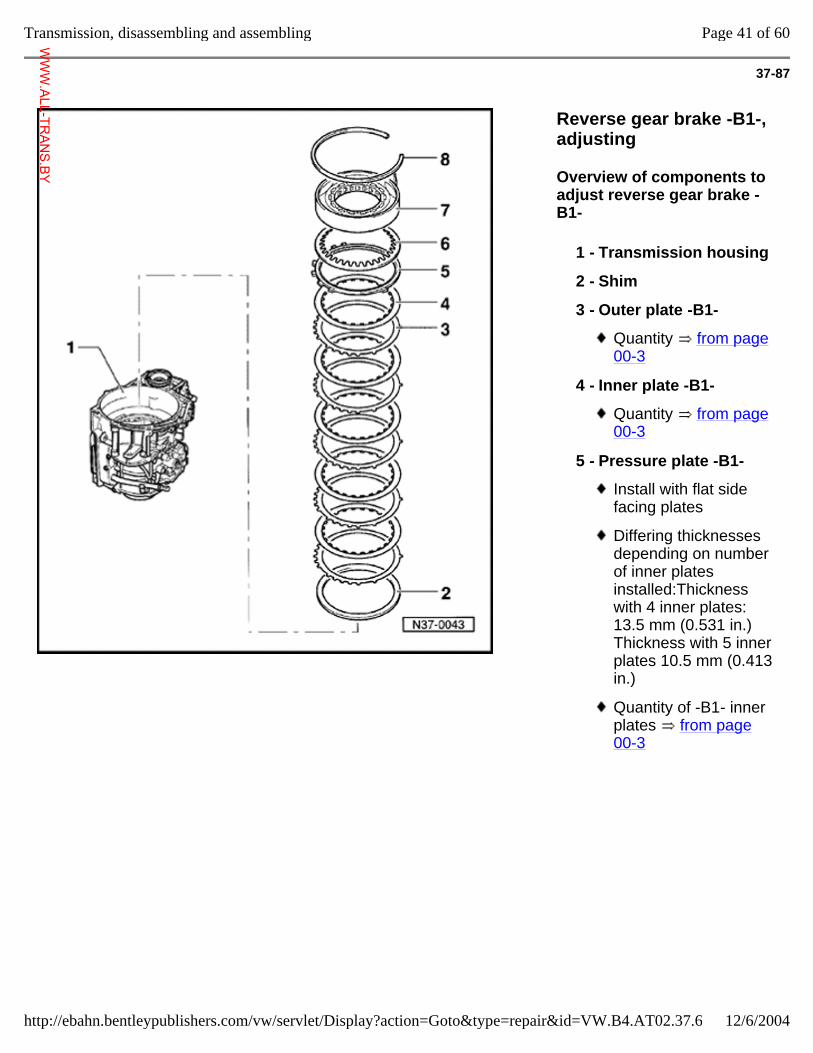
37-87
Reverse gear brake -B1-, adjusting
Overview of components to adjust reverse gear brake -B1-
1 - Transmission housing
2 - Shim
3 - Outer plate -B1-
Quantity from page 00-3
4 - Inner plate -B1-
Quantity from page 00-3
5 - Pressure plate -B1-
Install with flat side facing plates
Differing thicknesses depending on number of inner plates installed:Thickness with 4 inner plates: 13.5 mm (0.531 in.)Thickness with 5 inner plates 10.5 mm (0.413 in.)
Quantity of -B1- inner plates from page 00-3
Page 41 of 60Transmission, disassembling and assembling
12/6/2004http://ebahn.bentleypublishers.com/vw/servlet/Display?action=Goto&type=repair&id=VW.B4.AT02.37.6
WWW.ALL-TR
ANS.BY
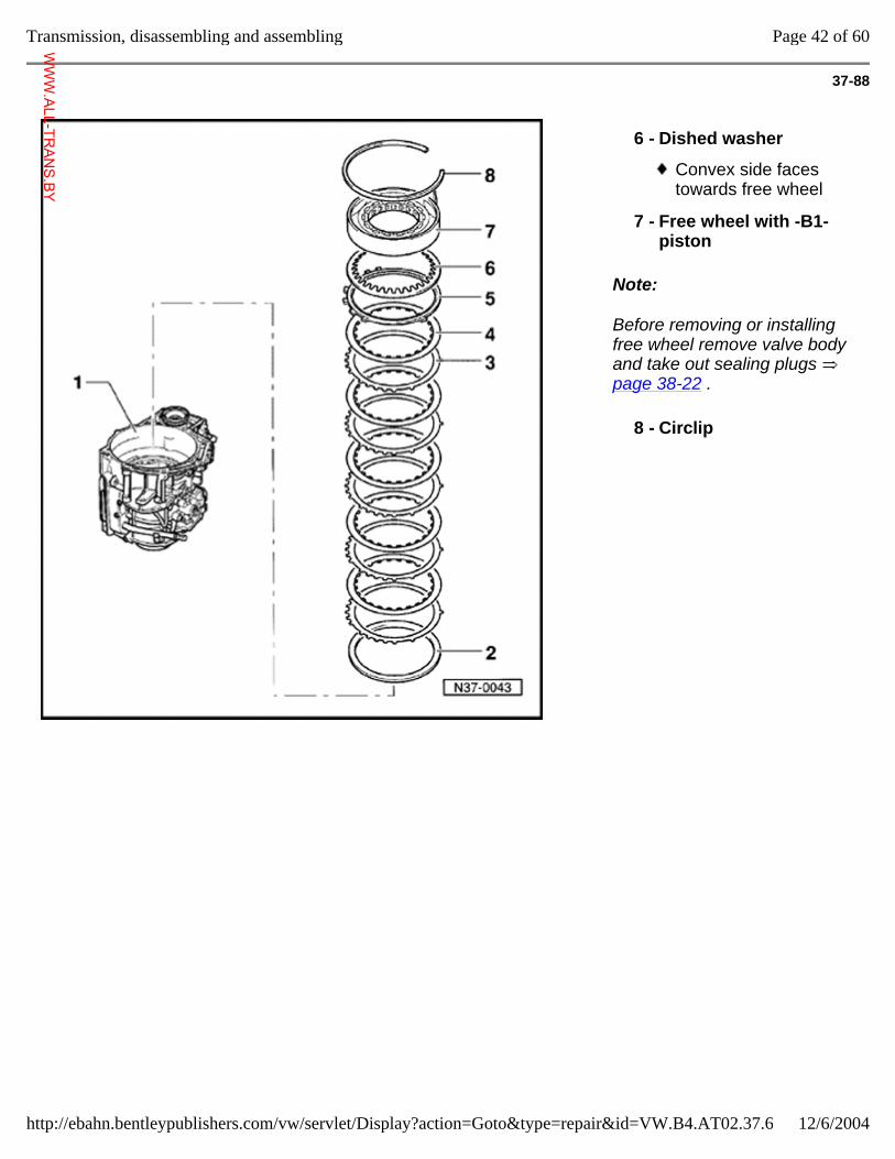
37-88
Note:
Before removing or installing free wheel remove valve body and take out sealing plugs page 38-22 .
6 - Dished washer
Convex side faces towards free wheel
7 - Free wheel with -B1- piston
8 - Circlip
Page 42 of 60Transmission, disassembling and assembling
12/6/2004http://ebahn.bentleypublishers.com/vw/servlet/Display?action=Goto&type=repair&id=VW.B4.AT02.37.6
WWW.ALL-TR
ANS.BY
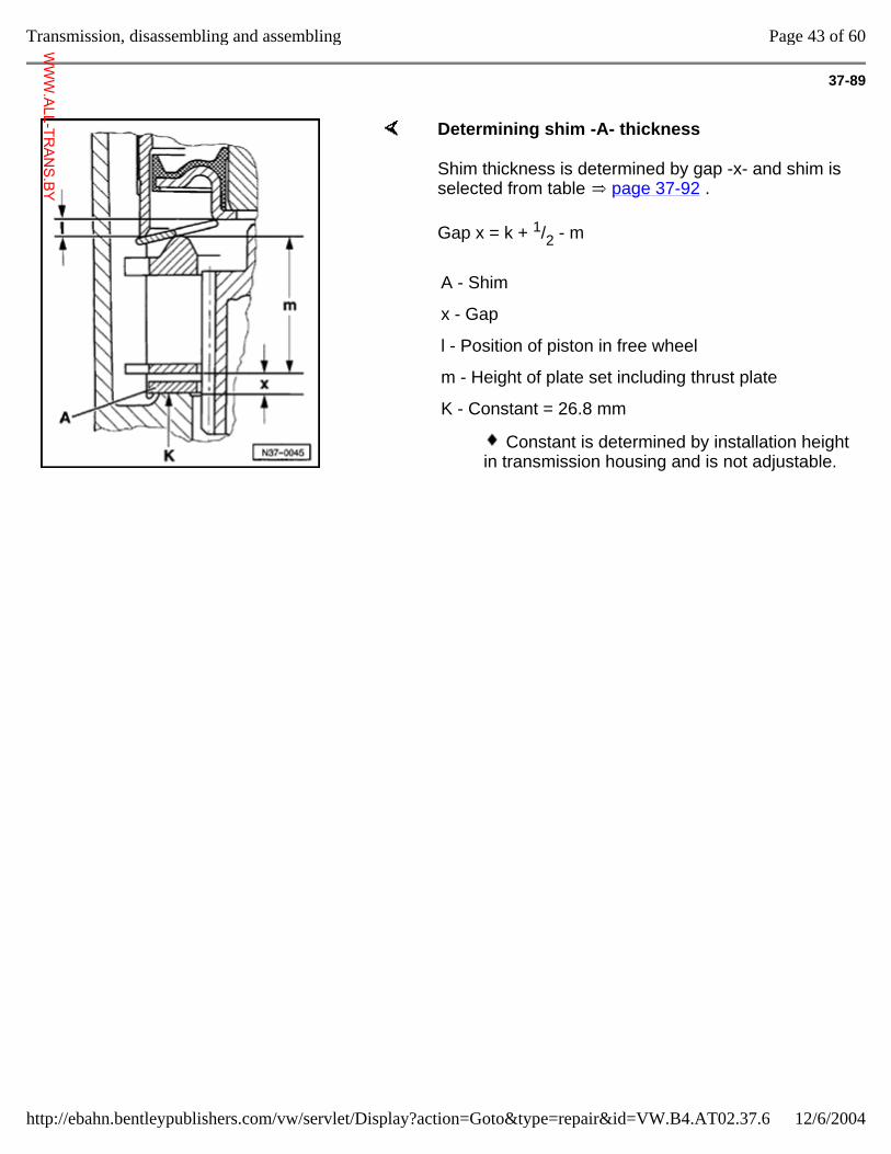
37-89
Determining shim -A- thickness
Shim thickness is determined by gap -x- and shim is selected from table page 37-92 .
Gap x = k + 1/2 - m
A - Shim
x - Gap
l - Position of piston in free wheel
m - Height of plate set including thrust plate
K - Constant = 26.8 mm
Constant is determined by installation height in transmission housing and is not adjustable.
Page 43 of 60Transmission, disassembling and assembling
12/6/2004http://ebahn.bentleypublishers.com/vw/servlet/Display?action=Goto&type=repair&id=VW.B4.AT02.37.6
WWW.ALL-TR
ANS.BY
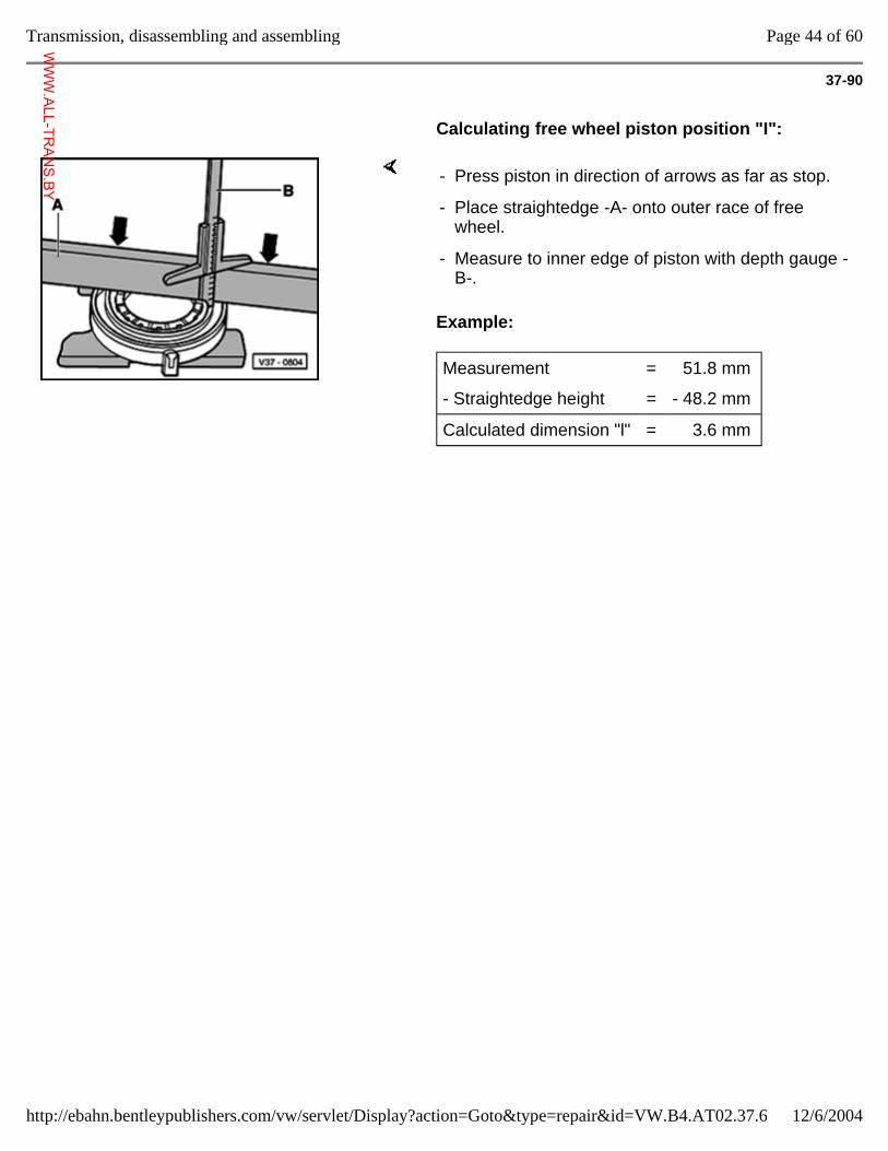
37-90
Calculating free wheel piston position "I":
Example:
- Press piston in direction of arrows as far as stop.
- Place straightedge -A- onto outer race of free wheel.
- Measure to inner edge of piston with depth gauge -B-.
Measurement = 51.8 mm
- Straightedge height = - 48.2 mm
Calculated dimension "l" = 3.6 mm
Page 44 of 60Transmission, disassembling and assembling
12/6/2004http://ebahn.bentleypublishers.com/vw/servlet/Display?action=Goto&type=repair&id=VW.B4.AT02.37.6
WWW.ALL-TR
ANS.BY
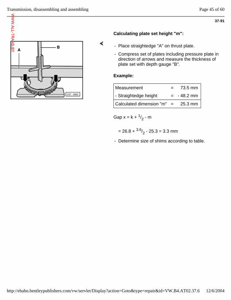
37-91
Calculating plate set height "m":
Example:
Gap x = k + 1/2 - m
- Place straightedge "A" on thrust plate.
- Compress set of plates including pressure plate in direction of arrows and measure the thickness of plate set with depth gauge "B".
Measurement = 73.5 mm
- Straightedge height = - 48.2 mm
Calculated dimension "m" = 25.3 mm
= 26.8 + 3.6/2 - 25.3 = 3.3 mm
- Determine size of shims according to table.
Page 45 of 60Transmission, disassembling and assembling
12/6/2004http://ebahn.bentleypublishers.com/vw/servlet/Display?action=Goto&type=repair&id=VW.B4.AT02.37.6
WWW.ALL-TR
ANS.BY
37-92
Table of shims
Gap "x" - mm Shim thickness - mm
2.36 - 2.45
2.46 - 2.55
2.56 - 2.65
1.0
1.1
1.2
2.66 - 2.75
2.76 - 2.85
2.86 - 2.95
1.3
1.4
1.5
2.96 - 3.05
3.06 - 3.15
3.16 - 3.25
1.6
1.7
1.8
3.26 - 3.35
3.36 - 3.45
3.46 - 3.55
1.9
1.0 + 1.0
1.0 + 1.1
3.56 - 3.65
3.66 - 3.75
3.76 - 3.85
1.1 + 1.1
1.1 + 1.2
1.2 + 1.2
3.86 - 3.95
3.96 - 4.05
4.06 - 4.15
1.2 + 1.3
1.3 + 1.3
1.3 + 1.4
4.16 - 4.25 1.4 + 1.4
- Determine thickness of shims according to table and determine Part No. from parts catalog microfiche.
- After determining shim for -B1- carry out check measurement page 37-93 .
Page 46 of 60Transmission, disassembling and assembling
12/6/2004http://ebahn.bentleypublishers.com/vw/servlet/Display?action=Goto&type=repair&id=VW.B4.AT02.37.6
WWW.ALL-TR
ANS.BY
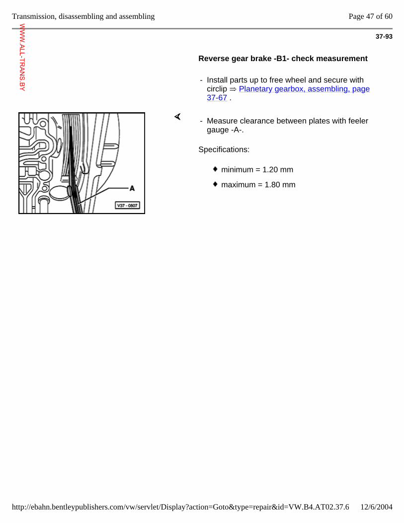
37-93
Reverse gear brake -B1- check measurement
- Install parts up to free wheel and secure with circlip Planetary gearbox, assembling, page 37-67 .
Specifications:
- Measure clearance between plates with feeler gauge -A-.
minimum = 1.20 mm
maximum = 1.80 mm
Page 47 of 60Transmission, disassembling and assembling
12/6/2004http://ebahn.bentleypublishers.com/vw/servlet/Display?action=Goto&type=repair&id=VW.B4.AT02.37.6
WWW.ALL-TR
ANS.BY
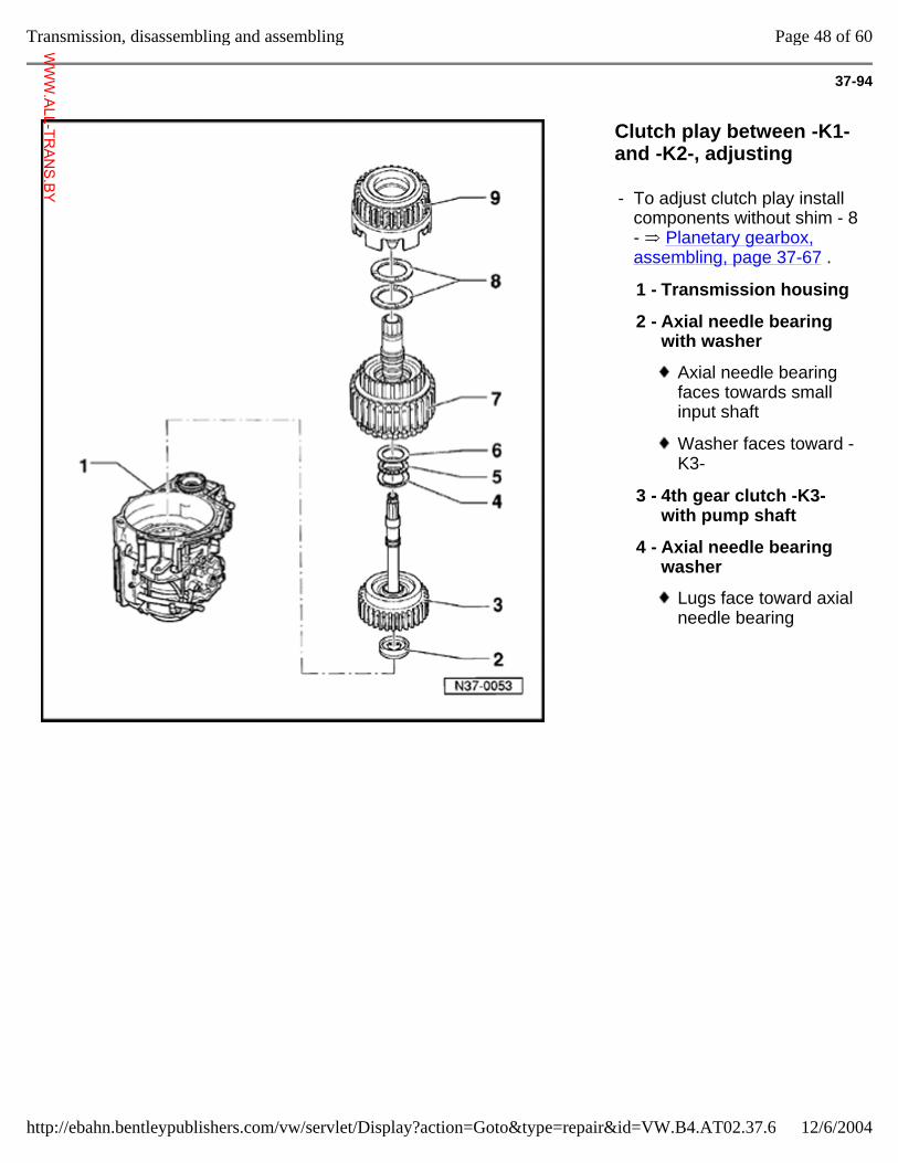
37-94
Clutch play between -K1- and -K2-, adjusting
- To adjust clutch play install components without shim - 8 - Planetary gearbox, assembling, page 37-67 .
1 - Transmission housing
2 - Axial needle bearing with washer
Axial needle bearing faces towards small input shaft
Washer faces toward -K3-
3 - 4th gear clutch -K3- with pump shaft
4 - Axial needle bearing washer
Lugs face toward axial needle bearing
Page 48 of 60Transmission, disassembling and assembling
12/6/2004http://ebahn.bentleypublishers.com/vw/servlet/Display?action=Goto&type=repair&id=VW.B4.AT02.37.6
WWW.ALL-TR
ANS.BY
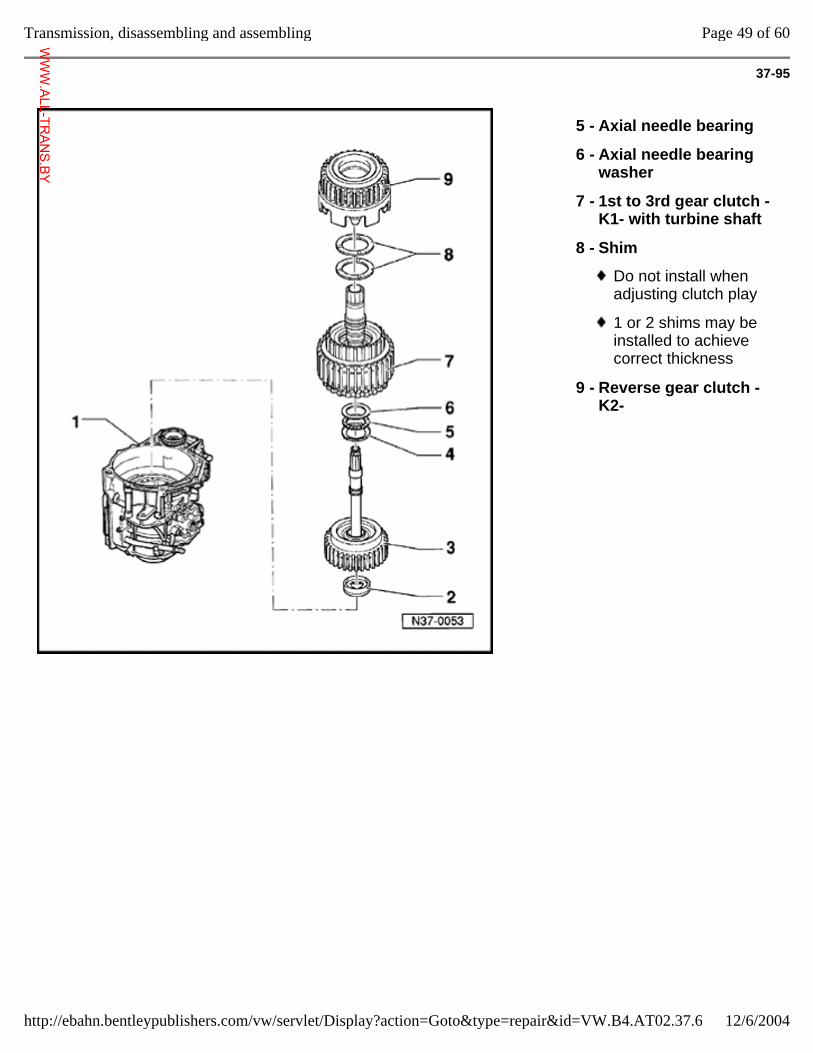
37-95
5 - Axial needle bearing
6 - Axial needle bearing washer
7 - 1st to 3rd gear clutch -K1- with turbine shaft
8 - Shim
Do not install when adjusting clutch play
1 or 2 shims may be installed to achieve correct thickness
9 - Reverse gear clutch -K2-
Page 49 of 60Transmission, disassembling and assembling
12/6/2004http://ebahn.bentleypublishers.com/vw/servlet/Display?action=Goto&type=repair&id=VW.B4.AT02.37.6
WWW.ALL-TR
ANS.BY
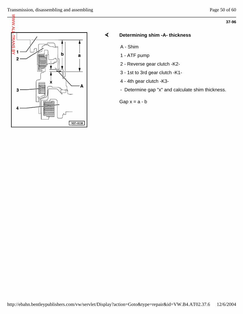
37-96
Determining shim -A- thickness
Gap x = a - b
A - Shim
1 - ATF pump
2 - Reverse gear clutch -K2-
3 - 1st to 3rd gear clutch -K1-
4 - 4th gear clutch -K3-
- Determine gap "x" and calculate shim thickness.
Page 50 of 60Transmission, disassembling and assembling
12/6/2004http://ebahn.bentleypublishers.com/vw/servlet/Display?action=Goto&type=repair&id=VW.B4.AT02.37.6
WWW.ALL-TR
ANS.BY
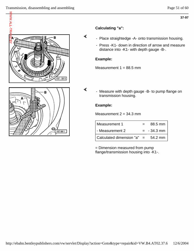
37-97
Calculating "a":
Example:
Measurement 1 = 88.5 mm
- Place straightedge -A- onto transmission housing.
- Press -K1- down in direction of arrow and measure distance into -K1- with depth gauge -B-.
Example:
Measurement 2 = 34.3 mm
= Dimension measured from pump flange/transmission housing into -K1-.
- Measure with depth gauge -B- to pump flange on transmission housing.
Measurement 1 = 88.5 mm
- Measurement 2 = - 34.3 mm
Calculated dimension "a" = 54.2 mm
Page 51 of 60Transmission, disassembling and assembling
12/6/2004http://ebahn.bentleypublishers.com/vw/servlet/Display?action=Goto&type=repair&id=VW.B4.AT02.37.6
WWW.ALL-TR
ANS.BY
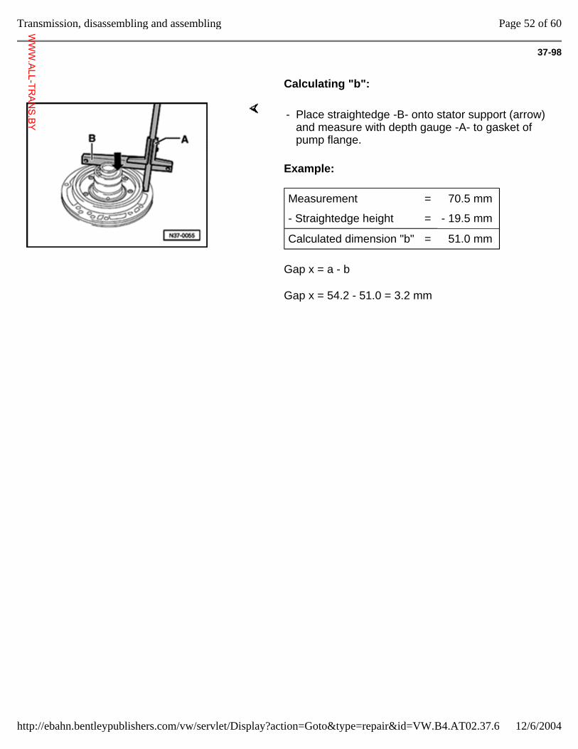
37-98
Calculating "b":
Example:
Gap x = a - b
Gap x = 54.2 - 51.0 = 3.2 mm
- Place straightedge -B- onto stator support (arrow) and measure with depth gauge -A- to gasket of pump flange.
Measurement = 70.5 mm
- Straightedge height = - 19.5 mm
Calculated dimension "b" = 51.0 mm
Page 52 of 60Transmission, disassembling and assembling
12/6/2004http://ebahn.bentleypublishers.com/vw/servlet/Display?action=Goto&type=repair&id=VW.B4.AT02.37.6
WWW.ALL-TR
ANS.BY
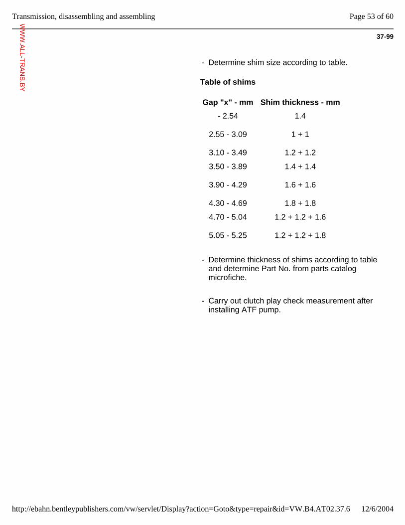
37-99
- Determine shim size according to table.
Table of shims
Gap "x" - mm Shim thickness - mm
- 2.54
2.55 - 3.09
3.10 - 3.49
1.4
1 + 1
1.2 + 1.2
3.50 - 3.89
3.90 - 4.29
4.30 - 4.69
1.4 + 1.4
1.6 + 1.6
1.8 + 1.8
4.70 - 5.04
5.05 - 5.25
1.2 + 1.2 + 1.6
1.2 + 1.2 + 1.8
- Determine thickness of shims according to table and determine Part No. from parts catalog microfiche.
- Carry out clutch play check measurement after installing ATF pump.
Page 53 of 60Transmission, disassembling and assembling
12/6/2004http://ebahn.bentleypublishers.com/vw/servlet/Display?action=Goto&type=repair&id=VW.B4.AT02.37.6
WWW.ALL-TR
ANS.BY
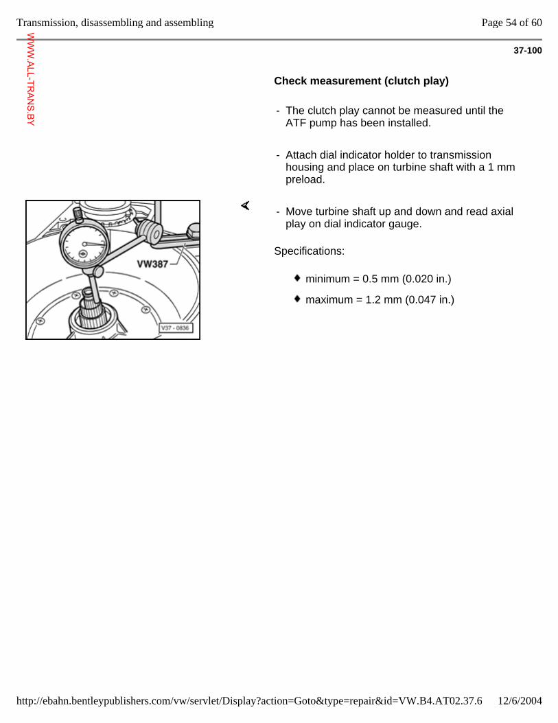
37-100
Check measurement (clutch play)
- The clutch play cannot be measured until the ATF pump has been installed.
- Attach dial indicator holder to transmission housing and place on turbine shaft with a 1 mm preload.
Specifications:
- Move turbine shaft up and down and read axial play on dial indicator gauge.
minimum = 0.5 mm (0.020 in.)
maximum = 1.2 mm (0.047 in.)
Page 54 of 60Transmission, disassembling and assembling
12/6/2004http://ebahn.bentleypublishers.com/vw/servlet/Display?action=Goto&type=repair&id=VW.B4.AT02.37.6
WWW.ALL-TR
ANS.BY
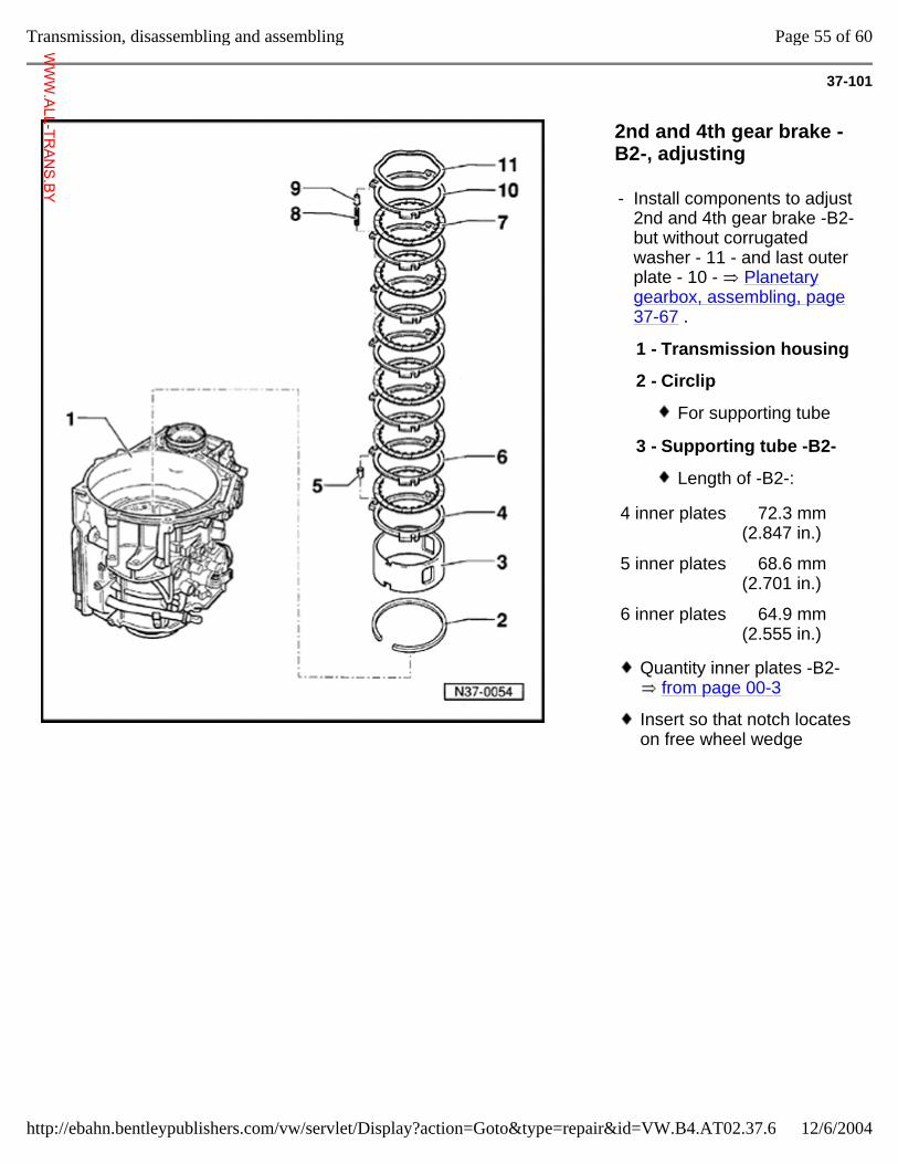
37-101
2nd and 4th gear brake -B2-, adjusting
- Install components to adjust 2nd and 4th gear brake -B2- but without corrugated washer - 11 - and last outer plate - 10 - Planetary gearbox, assembling, page 37-67 .
1 - Transmission housing
2 - Circlip
For supporting tube
3 - Supporting tube -B2-
Length of -B2-:
4 inner plates 72.3 mm (2.847 in.)
5 inner plates 68.6 mm (2.701 in.)
6 inner plates 64.9 mm (2.555 in.)
Quantity inner plates -B2- from page 00-3
Insert so that notch locates on free wheel wedge
Page 55 of 60Transmission, disassembling and assembling
12/6/2004http://ebahn.bentleypublishers.com/vw/servlet/Display?action=Goto&type=repair&id=VW.B4.AT02.37.6
WWW.ALL-TR
ANS.BY
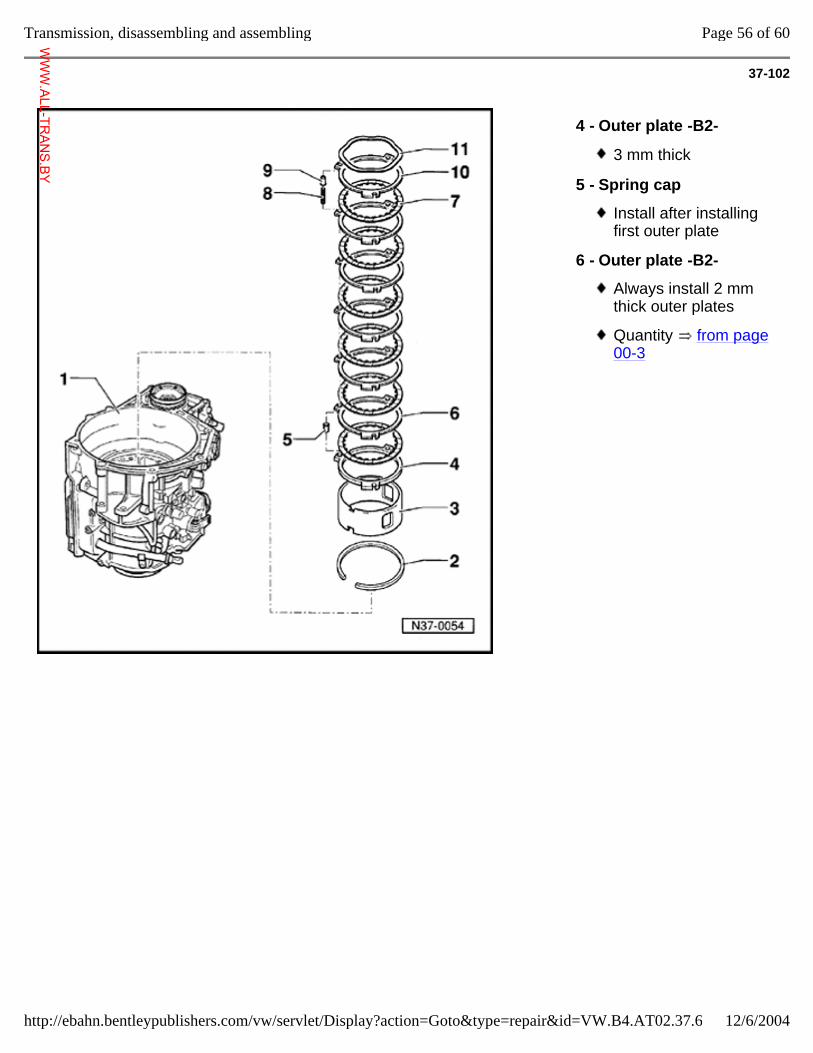
37-102
4 - Outer plate -B2-
3 mm thick
5 - Spring cap
Install after installing first outer plate
6 - Outer plate -B2-
Always install 2 mm thick outer plates
Quantity from page 00-3
Page 56 of 60Transmission, disassembling and assembling
12/6/2004http://ebahn.bentleypublishers.com/vw/servlet/Display?action=Goto&type=repair&id=VW.B4.AT02.37.6
WWW.ALL-TR
ANS.BY
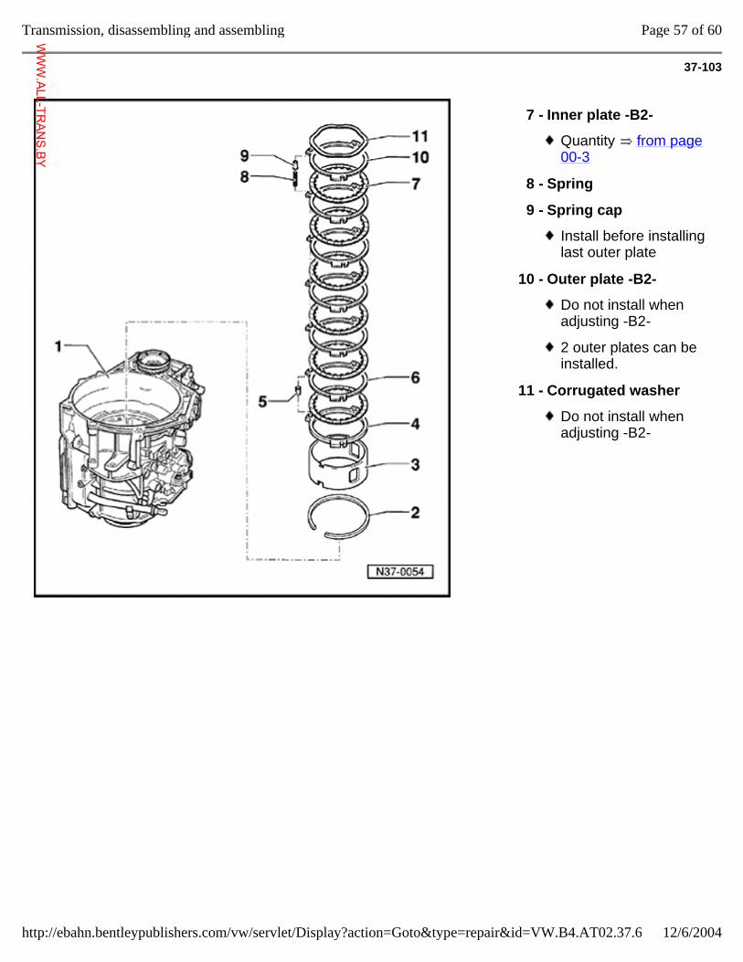
37-103
7 - Inner plate -B2-
Quantity from page 00-3
8 - Spring
9 - Spring cap
Install before installing last outer plate
10 - Outer plate -B2-
Do not install when adjusting -B2-
2 outer plates can be installed.
11 - Corrugated washer
Do not install when adjusting -B2-
Page 57 of 60Transmission, disassembling and assembling
12/6/2004http://ebahn.bentleypublishers.com/vw/servlet/Display?action=Goto&type=repair&id=VW.B4.AT02.37.6
WWW.ALL-TR
ANS.BY
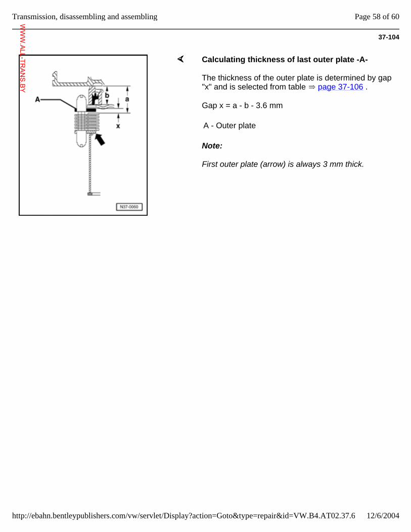
37-104
Calculating thickness of last outer plate -A-
The thickness of the outer plate is determined by gap "x" and is selected from table page 37-106 .
Gap x = a - b - 3.6 mm
Note:
First outer plate (arrow) is always 3 mm thick.
A - Outer plate
Page 58 of 60Transmission, disassembling and assembling
12/6/2004http://ebahn.bentleypublishers.com/vw/servlet/Display?action=Goto&type=repair&id=VW.B4.AT02.37.6
WWW.ALL-TR
ANS.BY
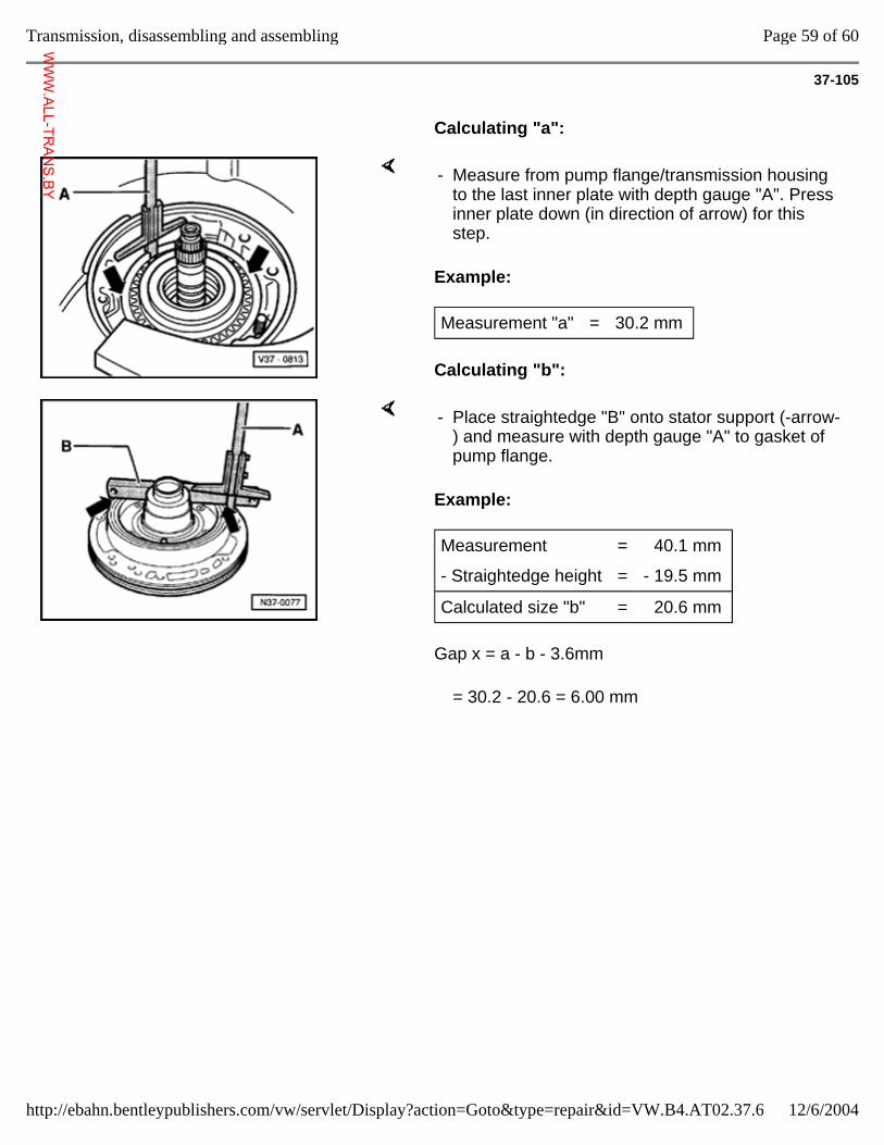
37-105
Calculating "a":
Example:
Calculating "b":
- Measure from pump flange/transmission housing to the last inner plate with depth gauge "A". Press inner plate down (in direction of arrow) for this step.
Measurement "a" = 30.2 mm
Example:
Gap x = a - b - 3.6mm
- Place straightedge "B" onto stator support (-arrow-) and measure with depth gauge "A" to gasket of pump flange.
Measurement = 40.1 mm
- Straightedge height = - 19.5 mm
Calculated size "b" = 20.6 mm
= 30.2 - 20.6 = 6.00 mm
Page 59 of 60Transmission, disassembling and assembling
12/6/2004http://ebahn.bentleypublishers.com/vw/servlet/Display?action=Goto&type=repair&id=VW.B4.AT02.37.6
WWW.ALL-TR
ANS.BY
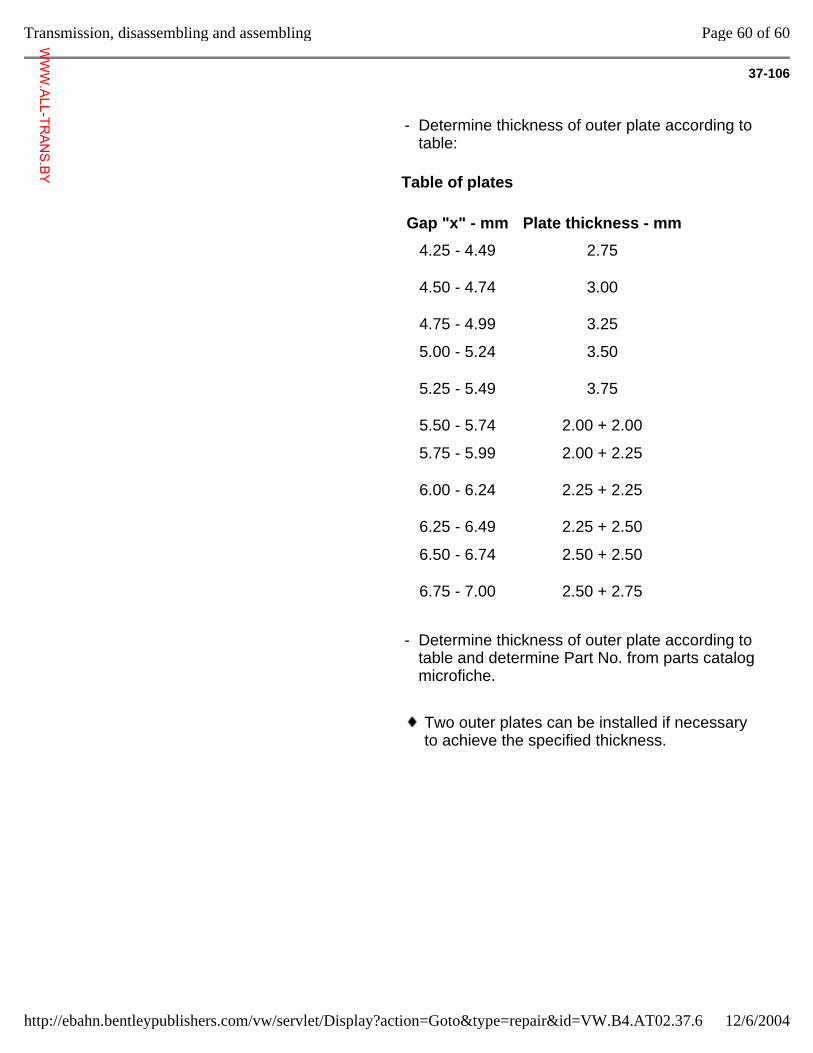
37-106
- Determine thickness of outer plate according to table:
Table of plates
Gap "x" - mm Plate thickness - mm
4.25 - 4.49
4.50 - 4.74
4.75 - 4.99
2.75
3.00
3.25
5.00 - 5.24
5.25 - 5.49
5.50 - 5.74
3.50
3.75
2.00 + 2.00
5.75 - 5.99
6.00 - 6.24
6.25 - 6.49
2.00 + 2.25
2.25 + 2.25
2.25 + 2.50
6.50 - 6.74
6.75 - 7.00
2.50 + 2.50
2.50 + 2.75
- Determine thickness of outer plate according to table and determine Part No. from parts catalog microfiche.
Two outer plates can be installed if necessary to achieve the specified thickness.
Page 60 of 60Transmission, disassembling and assembling
12/6/2004http://ebahn.bentleypublishers.com/vw/servlet/Display?action=Goto&type=repair&id=VW.B4.AT02.37.6
WWW.ALL-TR
ANS.BY
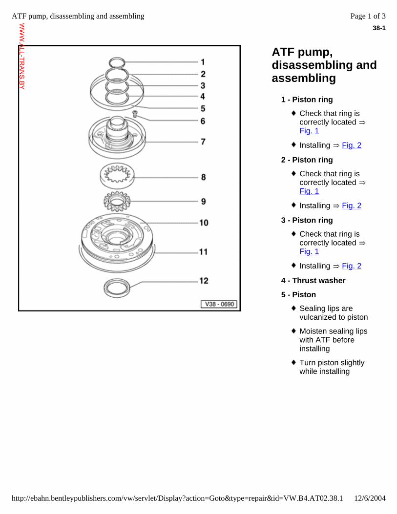
38-1
ATF pump, disassembling and assembling
1 - Piston ring
Check that ring is correctly located Fig. 1
Installing Fig. 2
2 - Piston ring
Check that ring is correctly located Fig. 1
Installing Fig. 2
3 - Piston ring
Check that ring is correctly located Fig. 1
Installing Fig. 2
4 - Thrust washer
5 - Piston
Sealing lips are vulcanized to piston
Moisten sealing lips with ATF before installing
Turn piston slightly while installing
Page 1 of 3ATF pump, disassembling and assembling
12/6/2004http://ebahn.bentleypublishers.com/vw/servlet/Display?action=Goto&type=repair&id=VW.B4.AT02.38.1
WWW.ALL-TR
ANS.BY
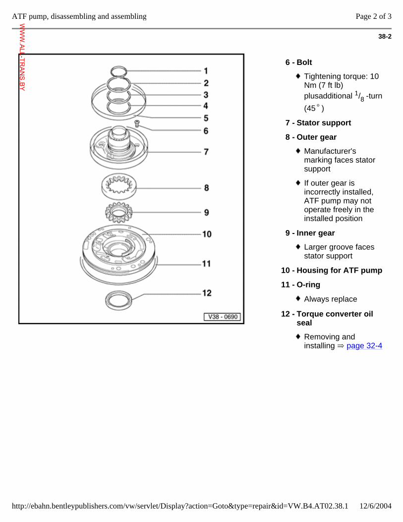
38-2
6 - Bolt
Tightening torque: 10 Nm (7 ft lb) plusadditional 1/8 -turn (45 )
7 - Stator support
8 - Outer gear
Manufacturer's marking faces stator support
If outer gear is incorrectly installed, ATF pump may not operate freely in the installed position
9 - Inner gear
Larger groove faces stator support
10 - Housing for ATF pump
11 - O-ring
Always replace
12 - Torque converter oil seal
Removing and installing page 32-4
Page 2 of 3ATF pump, disassembling and assembling
12/6/2004http://ebahn.bentleypublishers.com/vw/servlet/Display?action=Goto&type=repair&id=VW.B4.AT02.38.1
WWW.ALL-TR
ANS.BY
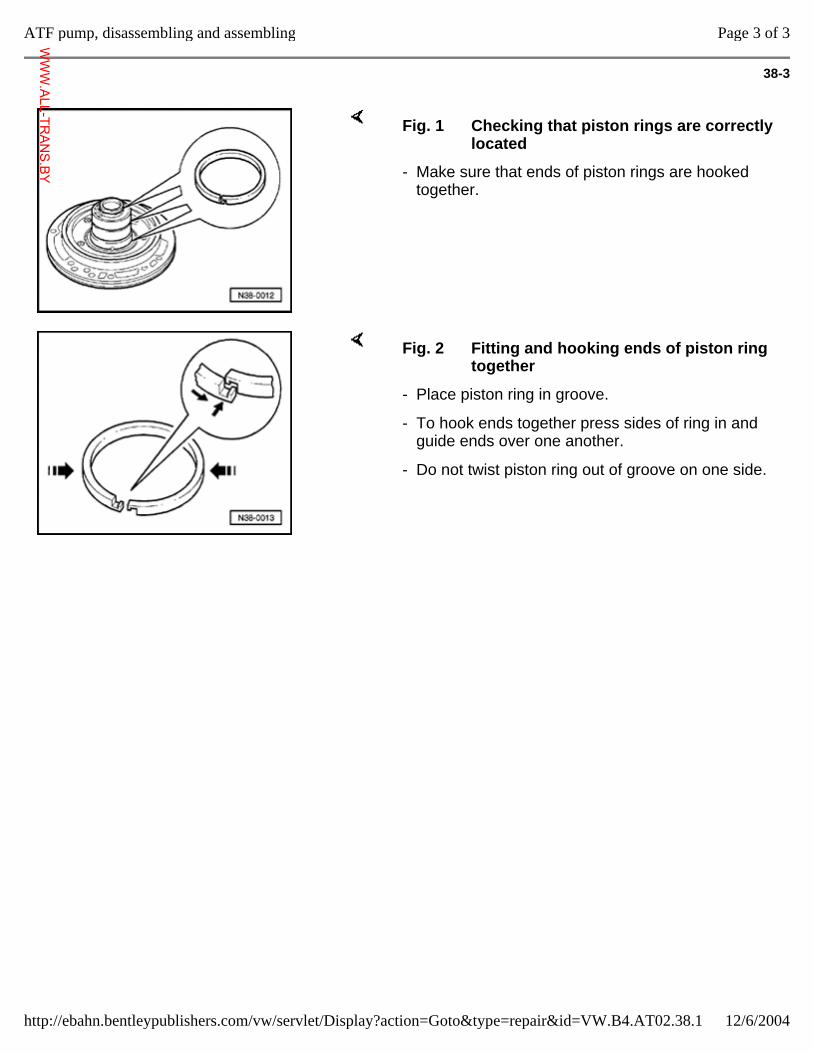
38-3
Fig. 1 Checking that piston rings are correctly located
- Make sure that ends of piston rings are hooked together.
Fig. 2 Fitting and hooking ends of piston ring together
- Place piston ring in groove.
- To hook ends together press sides of ring in and guide ends over one another.
- Do not twist piston ring out of groove on one side.
Page 3 of 3ATF pump, disassembling and assembling
12/6/2004http://ebahn.bentleypublishers.com/vw/servlet/Display?action=Goto&type=repair&id=VW.B4.AT02.38.1
WWW.ALL-TR
ANS.BY
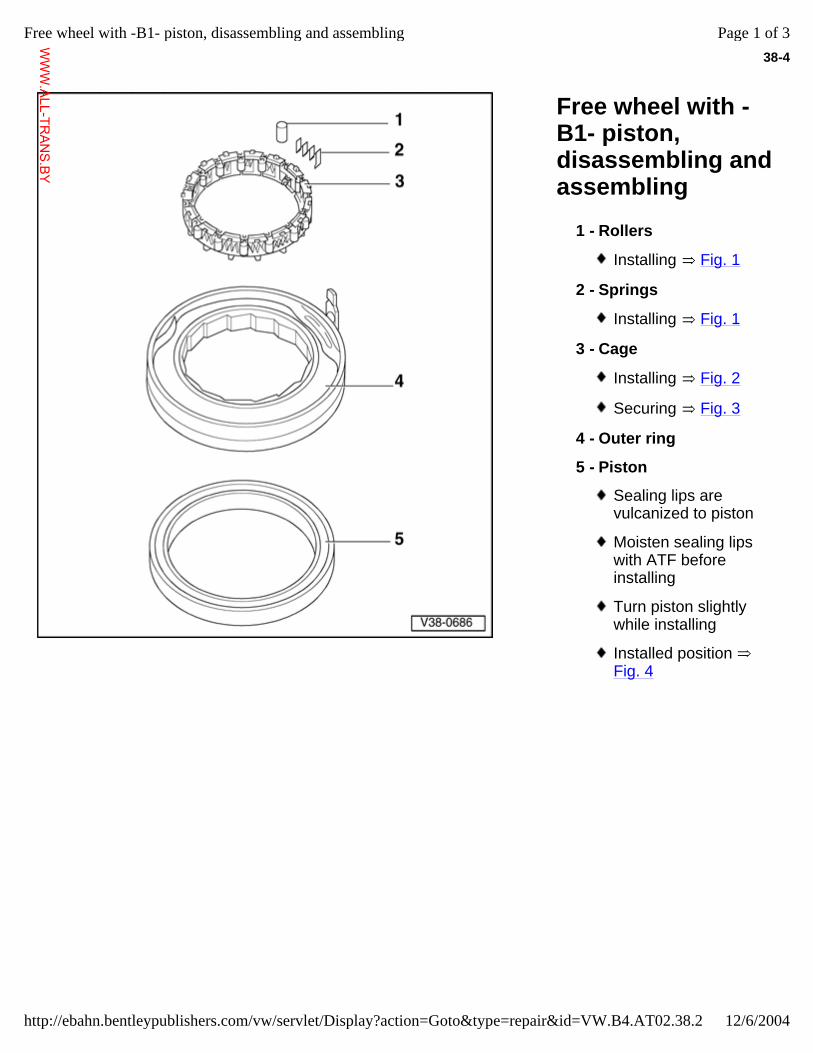
38-4
Free wheel with -B1- piston, disassembling and assembling
1 - Rollers
Installing Fig. 1
2 - Springs
Installing Fig. 1
3 - Cage
Installing Fig. 2
Securing Fig. 3
4 - Outer ring
5 - Piston
Sealing lips are vulcanized to piston
Moisten sealing lips with ATF before installing
Turn piston slightly while installing
Installed position Fig. 4
Page 1 of 3Free wheel with -B1- piston, disassembling and assembling
12/6/2004http://ebahn.bentleypublishers.com/vw/servlet/Display?action=Goto&type=repair&id=VW.B4.AT02.38.2
WWW.ALL-TR
ANS.BY
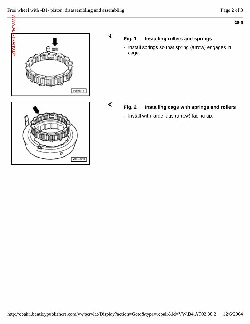
38-5
Fig. 1 Installing rollers and springs
- Install springs so that spring (arrow) engages in cage.
Fig. 2 Installing cage with springs and rollers
- Install with large lugs (arrow) facing up.
Page 2 of 3Free wheel with -B1- piston, disassembling and assembling
12/6/2004http://ebahn.bentleypublishers.com/vw/servlet/Display?action=Goto&type=repair&id=VW.B4.AT02.38.2
WWW.ALL-TR
ANS.BY
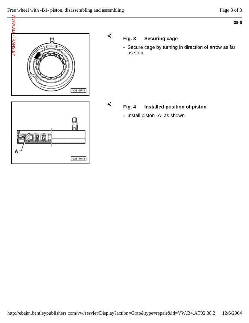
38-6
Fig. 3 Securing cage
- Secure cage by turning in direction of arrow as far as stop.
Fig. 4 Installed position of piston
- Install piston -A- as shown.
Page 3 of 3Free wheel with -B1- piston, disassembling and assembling
12/6/2004http://ebahn.bentleypublishers.com/vw/servlet/Display?action=Goto&type=repair&id=VW.B4.AT02.38.2
WWW.ALL-TR
ANS.BY
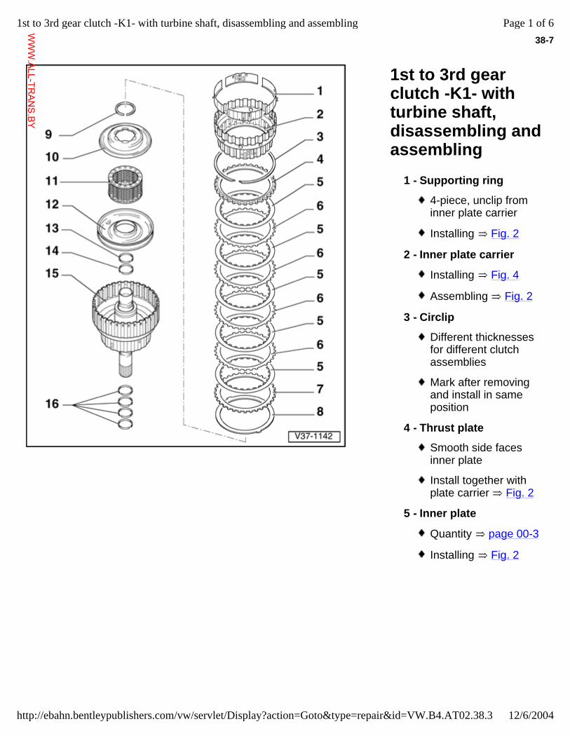
38-7
1st to 3rd gear clutch -K1- with turbine shaft, disassembling and assembling
1 - Supporting ring
4-piece, unclip from inner plate carrier
Installing Fig. 2
2 - Inner plate carrier
Installing Fig. 4
Assembling Fig. 2
3 - Circlip
Different thicknesses for different clutch assemblies
Mark after removing and install in same position
4 - Thrust plate
Smooth side faces inner plate
Install together with plate carrier Fig. 2
5 - Inner plate
Quantity page 00-3
Installing Fig. 2
Page 1 of 61st to 3rd gear clutch -K1- with turbine shaft, disassembling and assembling
12/6/2004http://ebahn.bentleypublishers.com/vw/servlet/Display?action=Goto&type=repair&id=VW.B4.AT02.38.3
WWW.ALL-TR
ANS.BY
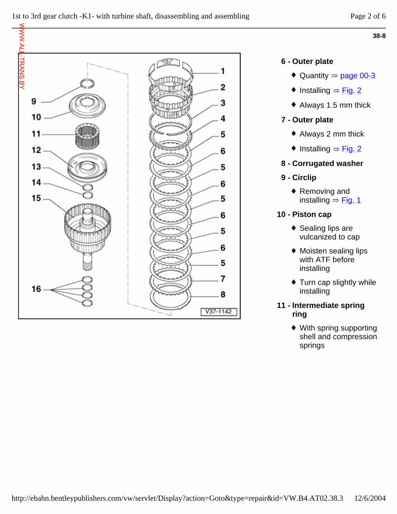
38-8
6 - Outer plate
Quantity page 00-3
Installing Fig. 2
Always 1.5 mm thick
7 - Outer plate
Always 2 mm thick
Installing Fig. 2
8 - Corrugated washer
9 - Circlip
Removing and installing Fig. 1
10 - Piston cap
Sealing lips are vulcanized to cap
Moisten sealing lips with ATF before installing
Turn cap slightly while installing
11 - Intermediate spring ring
With spring supporting shell and compression springs
Page 2 of 61st to 3rd gear clutch -K1- with turbine shaft, disassembling and assembling
12/6/2004http://ebahn.bentleypublishers.com/vw/servlet/Display?action=Goto&type=repair&id=VW.B4.AT02.38.3
WWW.ALL-TR
ANS.BY
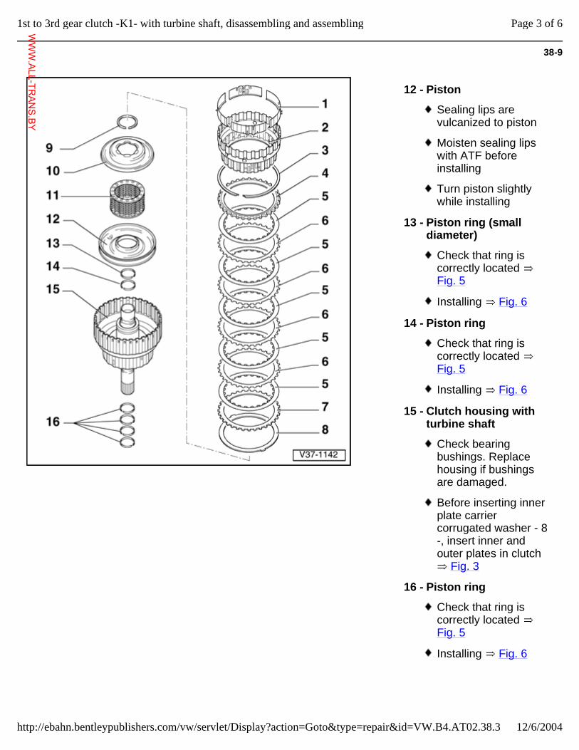
38-9
12 - Piston
Sealing lips are vulcanized to piston
Moisten sealing lips with ATF before installing
Turn piston slightly while installing
13 - Piston ring (small diameter)
Check that ring is correctly located Fig. 5
Installing Fig. 6
14 - Piston ring
Check that ring is correctly located Fig. 5
Installing Fig. 6
15 - Clutch housing with turbine shaft
Check bearing bushings. Replace housing if bushings are damaged.
Before inserting inner plate carrier corrugated washer - 8 -, insert inner and outer plates in clutch
Fig. 3
16 - Piston ring
Check that ring is correctly located Fig. 5
Installing Fig. 6
Page 3 of 61st to 3rd gear clutch -K1- with turbine shaft, disassembling and assembling
12/6/2004http://ebahn.bentleypublishers.com/vw/servlet/Display?action=Goto&type=repair&id=VW.B4.AT02.38.3
WWW.ALL-TR
ANS.BY
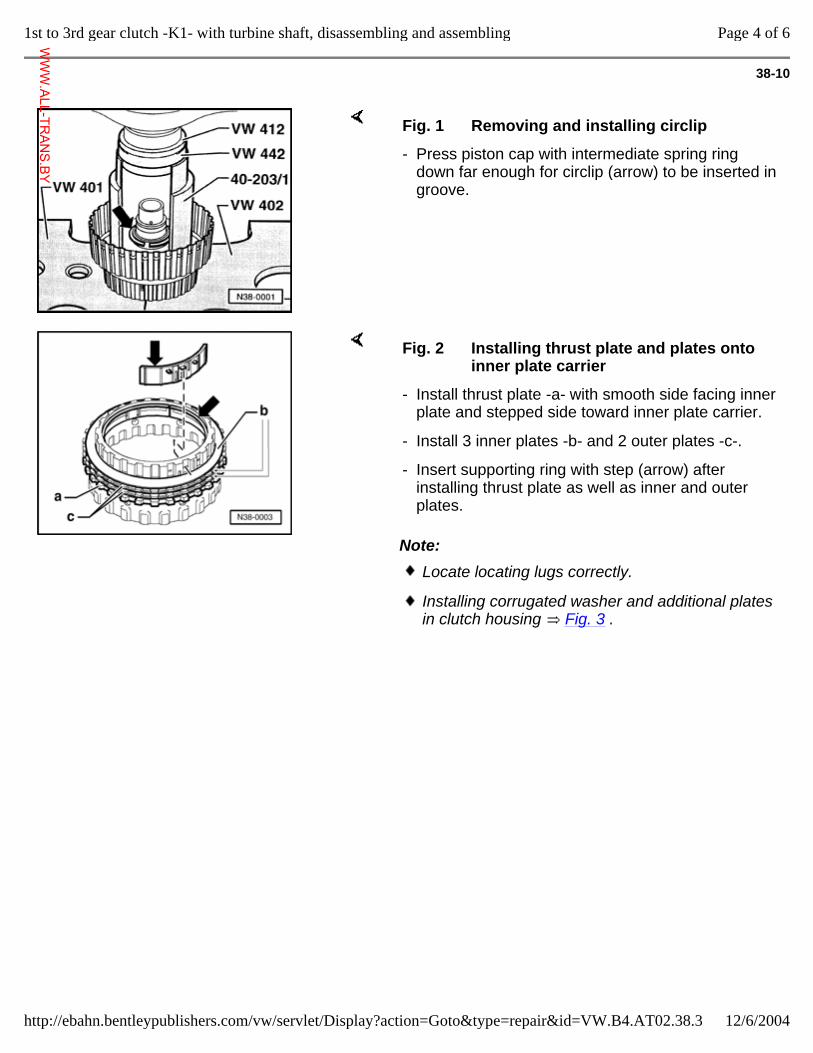
38-10
Fig. 1 Removing and installing circlip
- Press piston cap with intermediate spring ring down far enough for circlip (arrow) to be inserted in groove.
Note:
Fig. 2 Installing thrust plate and plates onto inner plate carrier
- Install thrust plate -a- with smooth side facing inner plate and stepped side toward inner plate carrier.
- Install 3 inner plates -b- and 2 outer plates -c-.
- Insert supporting ring with step (arrow) after installing thrust plate as well as inner and outer plates.
Locate locating lugs correctly.
Installing corrugated washer and additional plates in clutch housing Fig. 3 .
Page 4 of 61st to 3rd gear clutch -K1- with turbine shaft, disassembling and assembling
12/6/2004http://ebahn.bentleypublishers.com/vw/servlet/Display?action=Goto&type=repair&id=VW.B4.AT02.38.3
WWW.ALL-TR
ANS.BY
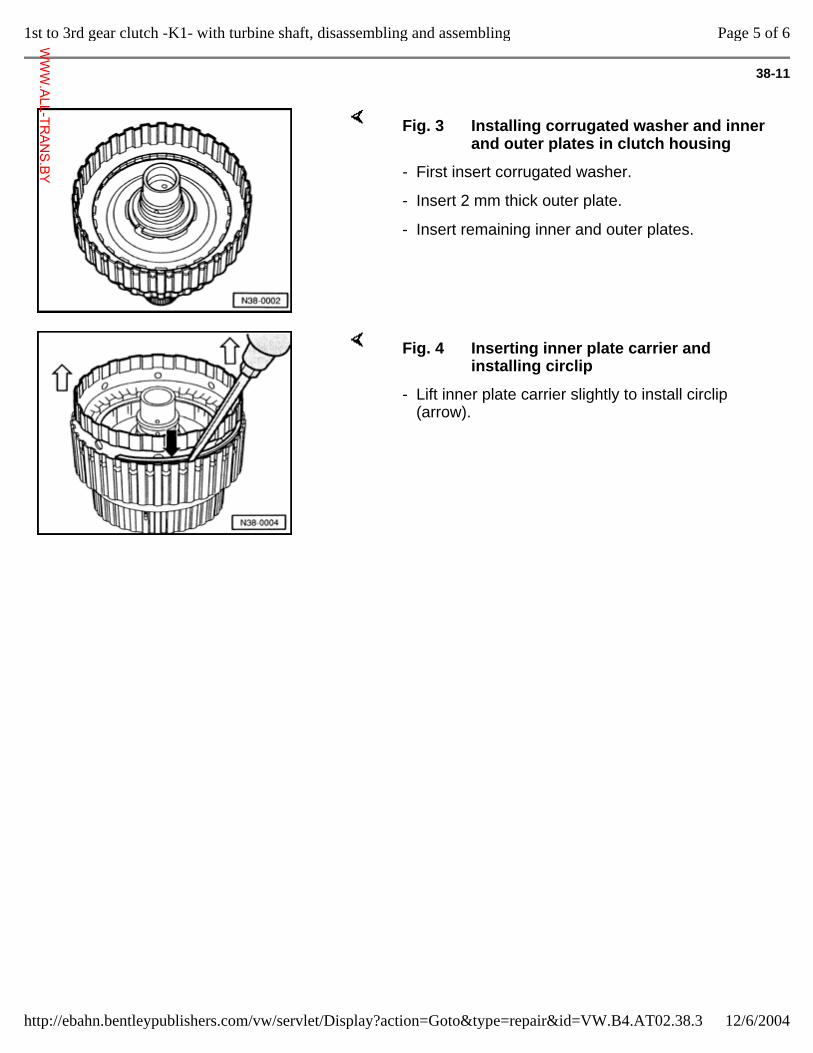
38-11
Fig. 3 Installing corrugated washer and inner and outer plates in clutch housing
- First insert corrugated washer.
- Insert 2 mm thick outer plate.
- Insert remaining inner and outer plates.
Fig. 4 Inserting inner plate carrier and installing circlip
- Lift inner plate carrier slightly to install circlip (arrow).
Page 5 of 61st to 3rd gear clutch -K1- with turbine shaft, disassembling and assembling
12/6/2004http://ebahn.bentleypublishers.com/vw/servlet/Display?action=Goto&type=repair&id=VW.B4.AT02.38.3
WWW.ALL-TR
ANS.BY
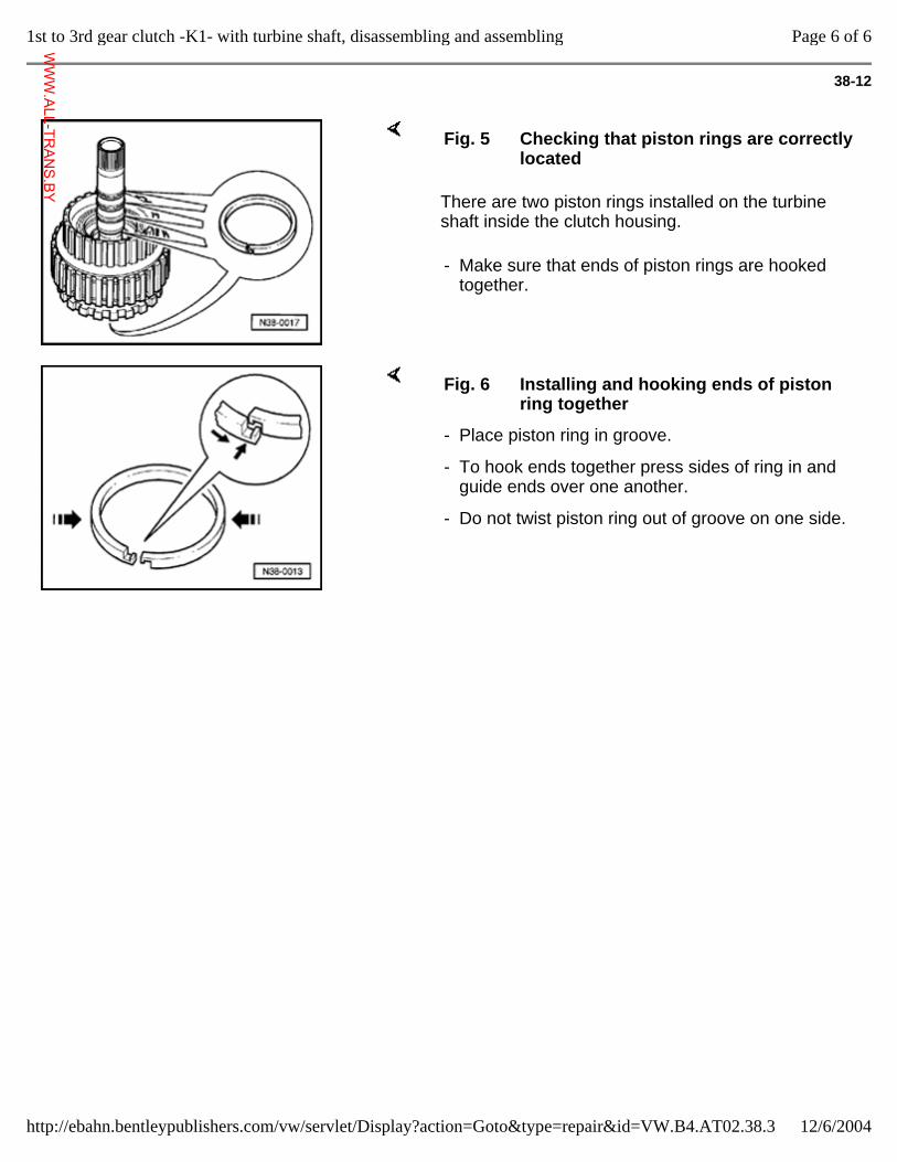
38-12
There are two piston rings installed on the turbine shaft inside the clutch housing.
Fig. 5 Checking that piston rings are correctly located
- Make sure that ends of piston rings are hooked together.
Fig. 6 Installing and hooking ends of piston ring together
- Place piston ring in groove.
- To hook ends together press sides of ring in and guide ends over one another.
- Do not twist piston ring out of groove on one side.
Page 6 of 61st to 3rd gear clutch -K1- with turbine shaft, disassembling and assembling
12/6/2004http://ebahn.bentleypublishers.com/vw/servlet/Display?action=Goto&type=repair&id=VW.B4.AT02.38.3
WWW.ALL-TR
ANS.BY
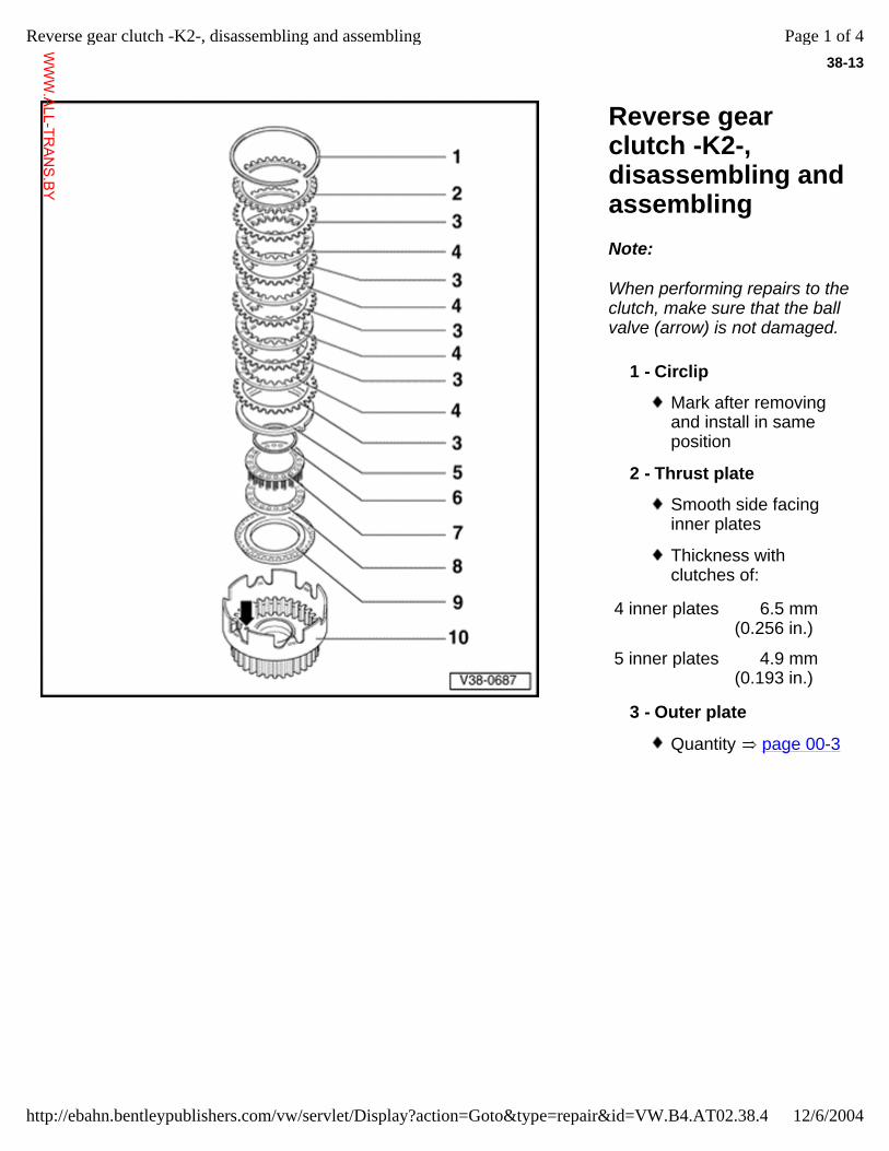
38-13
Reverse gear clutch -K2-, disassembling and assembling Note:
When performing repairs to the clutch, make sure that the ball valve (arrow) is not damaged.
1 - Circlip
Mark after removing and install in same position
2 - Thrust plate
Smooth side facing inner plates
Thickness with clutches of:
4 inner plates 6.5 mm (0.256 in.)
5 inner plates 4.9 mm (0.193 in.)
3 - Outer plate
Quantity page 00-3
Page 1 of 4Reverse gear clutch -K2-, disassembling and assembling
12/6/2004http://ebahn.bentleypublishers.com/vw/servlet/Display?action=Goto&type=repair&id=VW.B4.AT02.38.4
WWW.ALL-TR
ANS.BY
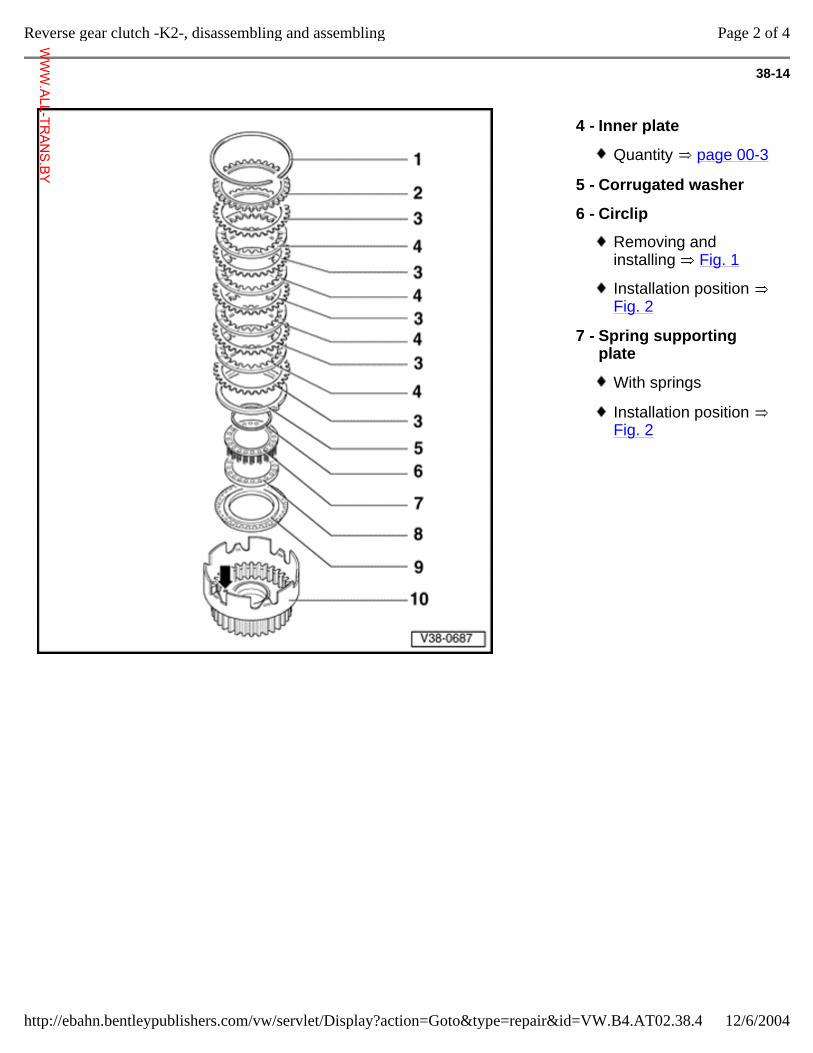
38-14
4 - Inner plate
Quantity page 00-3
5 - Corrugated washer
6 - Circlip
Removing and installing Fig. 1
Installation position Fig. 2
7 - Spring supporting plate
With springs
Installation position Fig. 2
Page 2 of 4Reverse gear clutch -K2-, disassembling and assembling
12/6/2004http://ebahn.bentleypublishers.com/vw/servlet/Display?action=Goto&type=repair&id=VW.B4.AT02.38.4
WWW.ALL-TR
ANS.BY
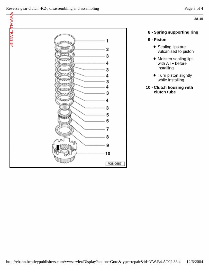
38-15
8 - Spring supporting ring
9 - Piston
Sealing lips are vulcanised to piston
Moisten sealing lips with ATF before installing
Turn piston slightly while installing
10 - Clutch housing with clutch tube
Page 3 of 4Reverse gear clutch -K2-, disassembling and assembling
12/6/2004http://ebahn.bentleypublishers.com/vw/servlet/Display?action=Goto&type=repair&id=VW.B4.AT02.38.4
WWW.ALL-TR
ANS.BY
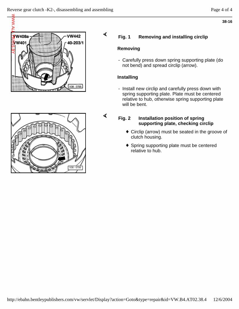
38-16
Removing
Installing
Fig. 1 Removing and installing circlip
- Carefully press down spring supporting plate (do not bend) and spread circlip (arrow).
- Install new circlip and carefully press down with spring supporting plate. Plate must be centered relative to hub, otherwise spring supporting plate will be bent.
Fig. 2 Installation position of spring supporting plate, checking circlip
Circlip (arrow) must be seated in the groove of clutch housing.
Spring supporting plate must be centered relative to hub.
Page 4 of 4Reverse gear clutch -K2-, disassembling and assembling
12/6/2004http://ebahn.bentleypublishers.com/vw/servlet/Display?action=Goto&type=repair&id=VW.B4.AT02.38.4
WWW.ALL-TR
ANS.BY
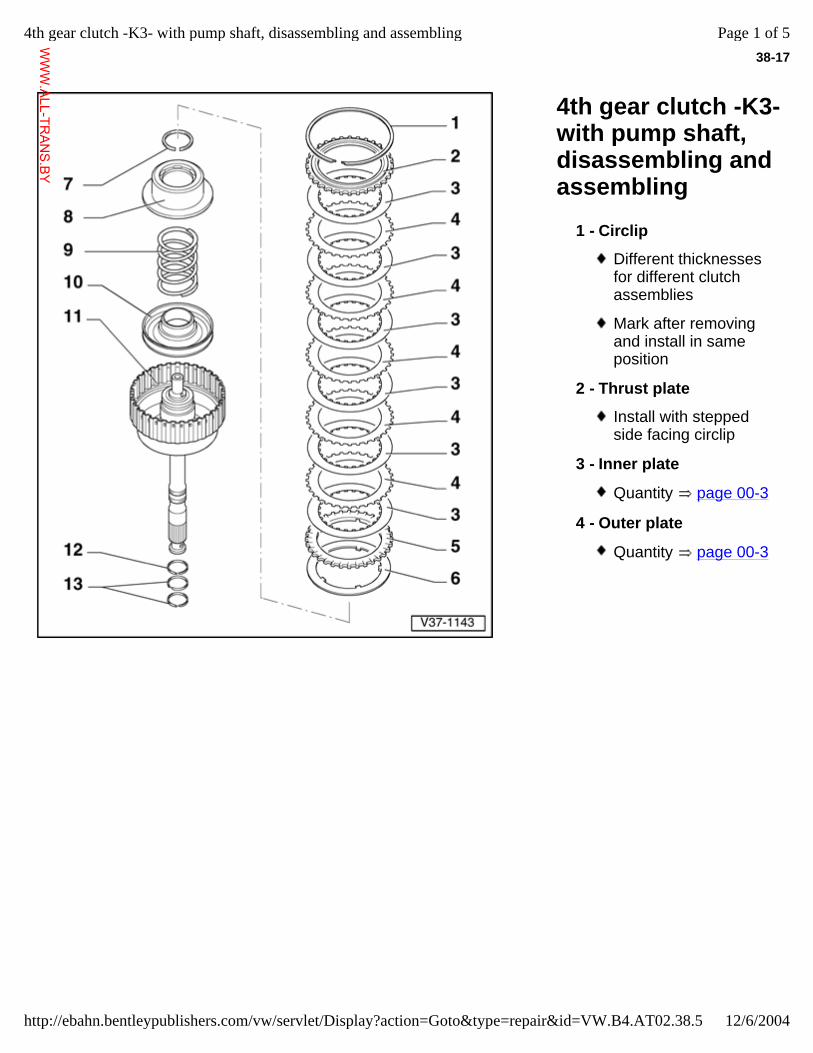
38-17
4th gear clutch -K3- with pump shaft, disassembling and assembling
1 - Circlip
Different thicknesses for different clutch assemblies
Mark after removing and install in same position
2 - Thrust plate
Install with stepped side facing circlip
3 - Inner plate
Quantity page 00-3
4 - Outer plate
Quantity page 00-3
Page 1 of 54th gear clutch -K3- with pump shaft, disassembling and assembling
12/6/2004http://ebahn.bentleypublishers.com/vw/servlet/Display?action=Goto&type=repair&id=VW.B4.AT02.38.5
WWW.ALL-TR
ANS.BY
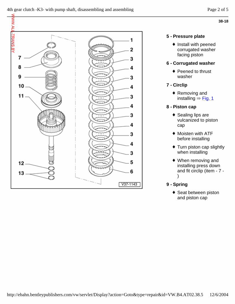
38-18
5 - Pressure plate
Install with peened corrugated washer facing piston
6 - Corrugated washer
Peened to thrust washer
7 - Circlip
Removing and installing Fig. 1
8 - Piston cap
Sealing lips are vulcanized to piston cap
Moisten with ATF before installing
Turn piston cap slightly when installing
When removing and installing press down and fit circlip (item - 7 -)
9 - Spring
Seat between piston and piston cap
Page 2 of 54th gear clutch -K3- with pump shaft, disassembling and assembling
12/6/2004http://ebahn.bentleypublishers.com/vw/servlet/Display?action=Goto&type=repair&id=VW.B4.AT02.38.5
WWW.ALL-TR
ANS.BY
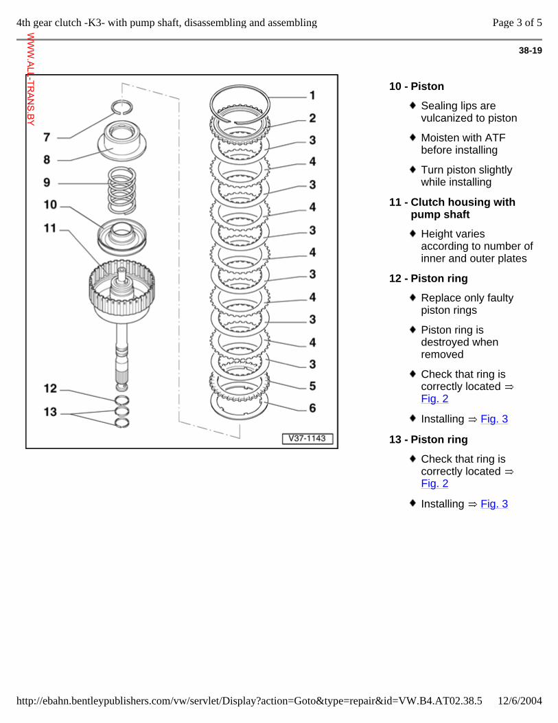
38-19
10 - Piston
Sealing lips are vulcanized to piston
Moisten with ATF before installing
Turn piston slightly while installing
11 - Clutch housing with pump shaft
Height varies according to number of inner and outer plates
12 - Piston ring
Replace only faulty piston rings
Piston ring is destroyed when removed
Check that ring is correctly located Fig. 2
Installing Fig. 3
13 - Piston ring
Check that ring is correctly located Fig. 2
Installing Fig. 3
Page 3 of 54th gear clutch -K3- with pump shaft, disassembling and assembling
12/6/2004http://ebahn.bentleypublishers.com/vw/servlet/Display?action=Goto&type=repair&id=VW.B4.AT02.38.5
WWW.ALL-TR
ANS.BY
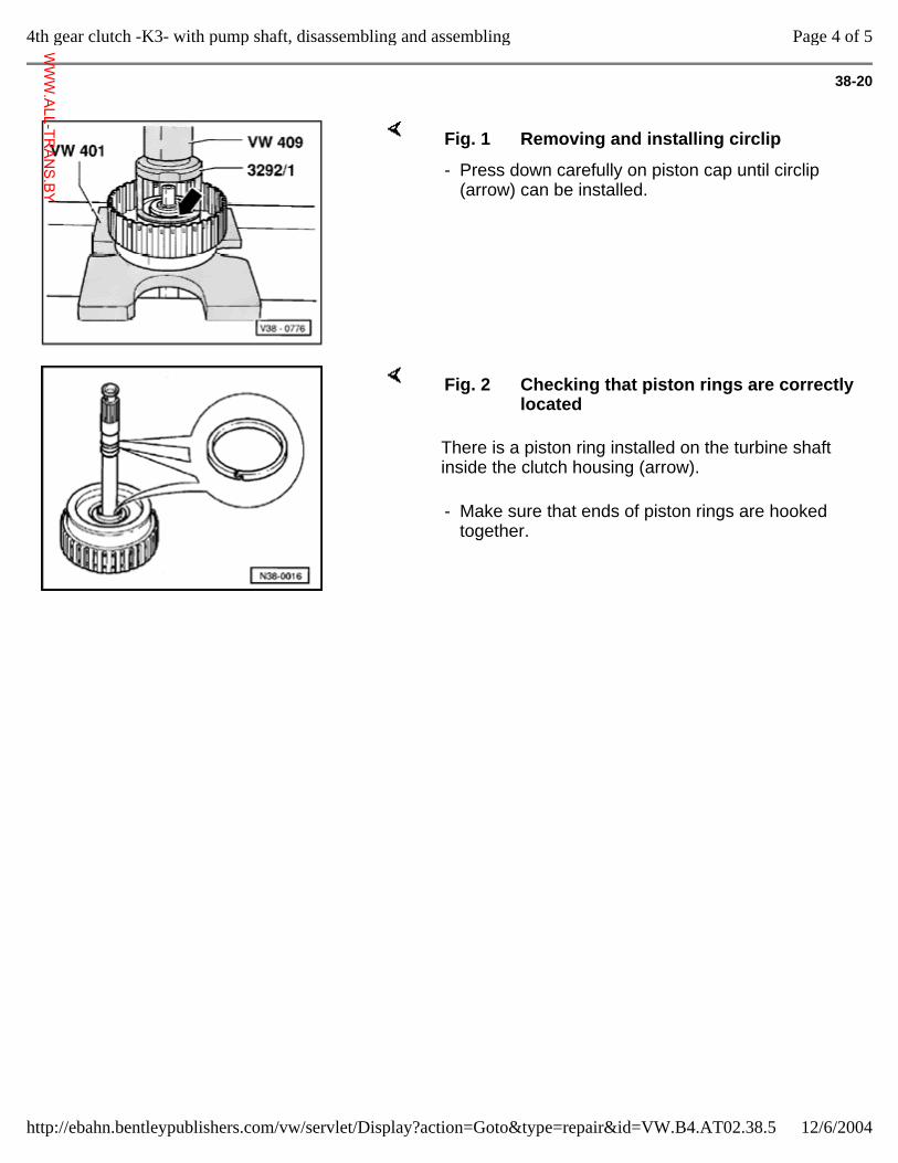
38-20
Fig. 1 Removing and installing circlip
- Press down carefully on piston cap until circlip (arrow) can be installed.
There is a piston ring installed on the turbine shaft inside the clutch housing (arrow).
Fig. 2 Checking that piston rings are correctly located
- Make sure that ends of piston rings are hooked together.
Page 4 of 54th gear clutch -K3- with pump shaft, disassembling and assembling
12/6/2004http://ebahn.bentleypublishers.com/vw/servlet/Display?action=Goto&type=repair&id=VW.B4.AT02.38.5
WWW.ALL-TR
ANS.BY
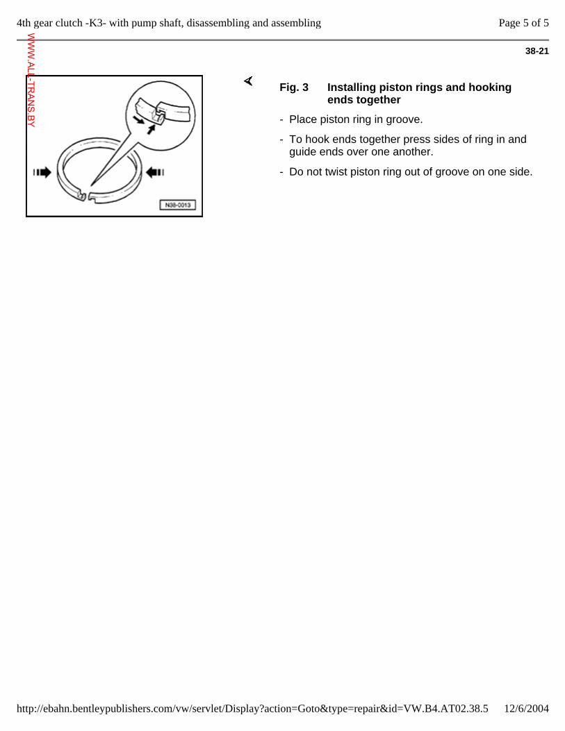
38-21
Fig. 3 Installing piston rings and hooking ends together
- Place piston ring in groove.
- To hook ends together press sides of ring in and guide ends over one another.
- Do not twist piston ring out of groove on one side.
Page 5 of 54th gear clutch -K3- with pump shaft, disassembling and assembling
12/6/2004http://ebahn.bentleypublishers.com/vw/servlet/Display?action=Goto&type=repair&id=VW.B4.AT02.38.5
WWW.ALL-TR
ANS.BY
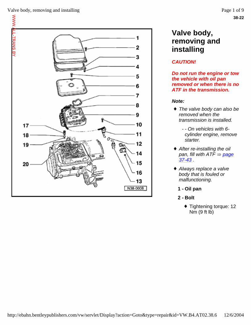
38-22
Valve body, removing and installing CAUTION!
Do not run the engine or tow the vehicle with oil pan removed or when there is no ATF in the transmission.
Note: The valve body can also be removed when the transmission is installed.
- - On vehicles with 6-cylinder engine, remove starter.
After re-installing the oil pan, fill with ATF page 37-43 .
Always replace a valve body that is fouled or malfunctioning.
1 - Oil pan
2 - Bolt
Tightening torque: 12 Nm (9 ft lb)
Page 1 of 9Valve body, removing and installing
12/6/2004http://ebahn.bentleypublishers.com/vw/servlet/Display?action=Goto&type=repair&id=VW.B4.AT02.38.6
WWW.ALL-TR
ANS.BY
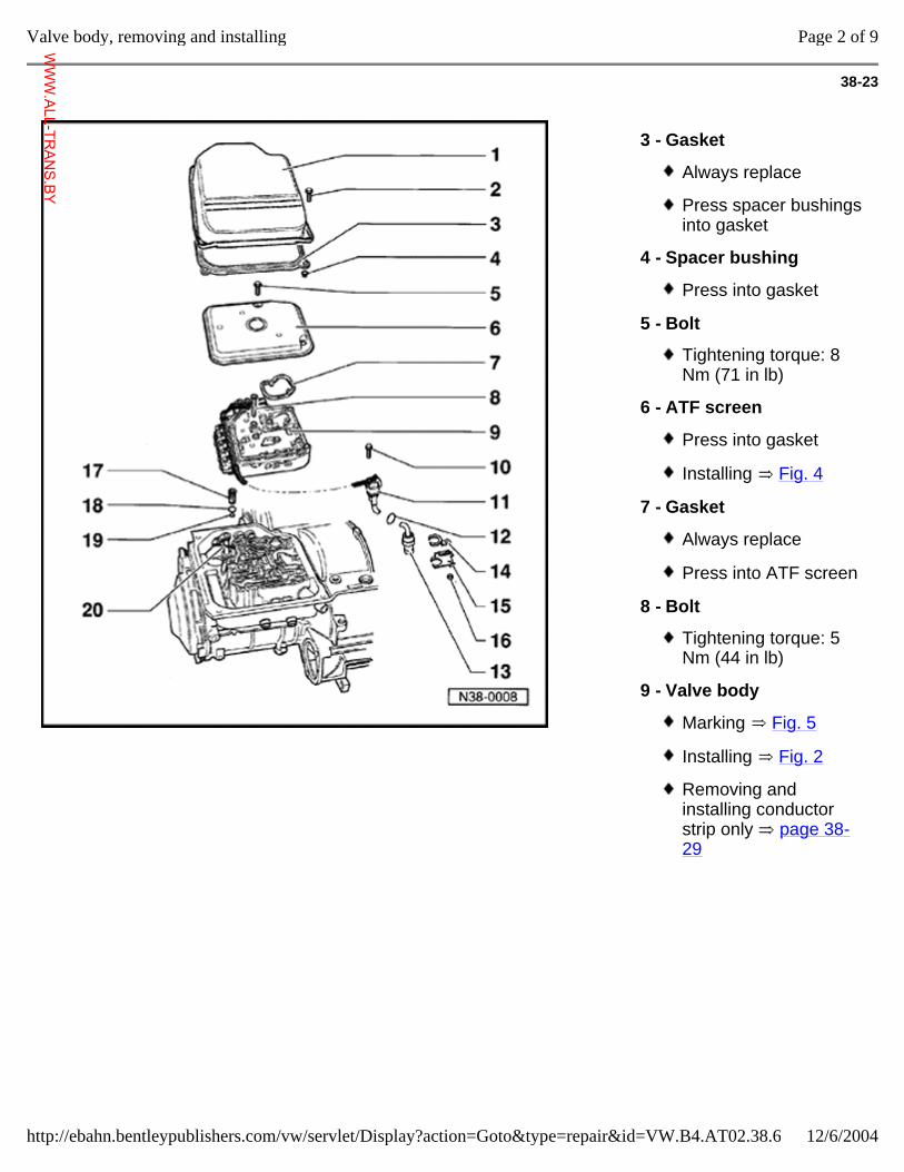
38-23
3 - Gasket
Always replace
Press spacer bushings into gasket
4 - Spacer bushing
Press into gasket
5 - Bolt
Tightening torque: 8 Nm (71 in lb)
6 - ATF screen
Press into gasket
Installing Fig. 4
7 - Gasket
Always replace
Press into ATF screen
8 - Bolt
Tightening torque: 5 Nm (44 in lb)
9 - Valve body
Marking Fig. 5
Installing Fig. 2
Removing and installing conductor strip only page 38-29
Page 2 of 9Valve body, removing and installing
12/6/2004http://ebahn.bentleypublishers.com/vw/servlet/Display?action=Goto&type=repair&id=VW.B4.AT02.38.6
WWW.ALL-TR
ANS.BY
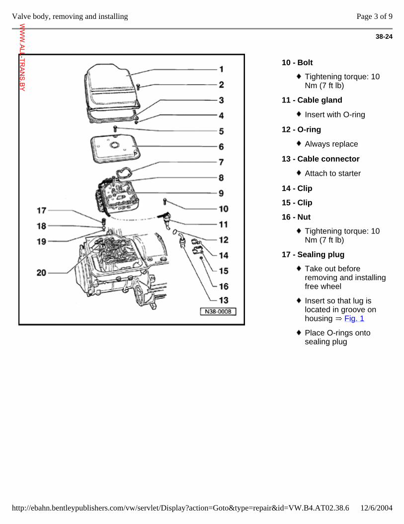
38-24
10 - Bolt
Tightening torque: 10 Nm (7 ft lb)
11 - Cable gland
Insert with O-ring
12 - O-ring
Always replace
13 - Cable connector
Attach to starter
14 - Clip
15 - Clip
16 - Nut
Tightening torque: 10 Nm (7 ft lb)
17 - Sealing plug
Take out before removing and installing free wheel
Insert so that lug is located in groove on housing Fig. 1
Place O-rings onto sealing plug
Page 3 of 9Valve body, removing and installing
12/6/2004http://ebahn.bentleypublishers.com/vw/servlet/Display?action=Goto&type=repair&id=VW.B4.AT02.38.6
WWW.ALL-TR
ANS.BY
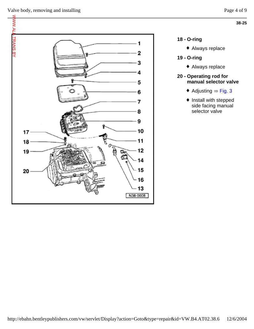
38-25
18 - O-ring
Always replace
19 - O-ring
Always replace
20 - Operating rod for manual selector valve
Adjusting Fig. 3
Install with stepped side facing manual selector valve
Page 4 of 9Valve body, removing and installing
12/6/2004http://ebahn.bentleypublishers.com/vw/servlet/Display?action=Goto&type=repair&id=VW.B4.AT02.38.6
WWW.ALL-TR
ANS.BY
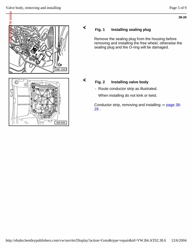
38-26
Remove the sealing plug from the housing before removing and installing the free wheel, otherwise the sealing plug and the O-ring will be damaged.
Fig. 1 Installing sealing plug
Conductor strip, removing and installing page 38-29 .
Fig. 2 Installing valve body
- Route conductor strip as illustrated.
When installing do not kink or twist.
Page 5 of 9Valve body, removing and installing
12/6/2004http://ebahn.bentleypublishers.com/vw/servlet/Display?action=Goto&type=repair&id=VW.B4.AT02.38.6
WWW.ALL-TR
ANS.BY
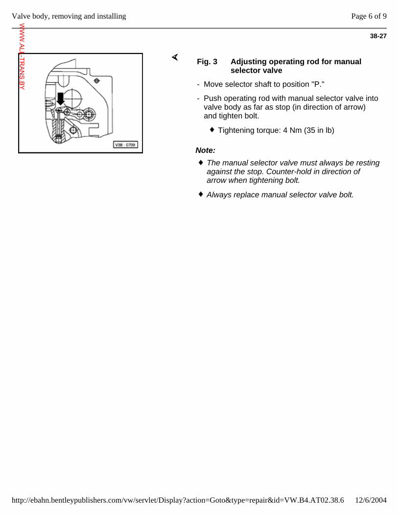
38-27
Note:
Fig. 3 Adjusting operating rod for manual selector valve
- Move selector shaft to position "P."
- Push operating rod with manual selector valve into valve body as far as stop (in direction of arrow) and tighten bolt.
Tightening torque: 4 Nm (35 in lb)
The manual selector valve must always be resting against the stop. Counter-hold in direction of arrow when tightening bolt.
Always replace manual selector valve bolt.
Page 6 of 9Valve body, removing and installing
12/6/2004http://ebahn.bentleypublishers.com/vw/servlet/Display?action=Goto&type=repair&id=VW.B4.AT02.38.6
WWW.ALL-TR
ANS.BY
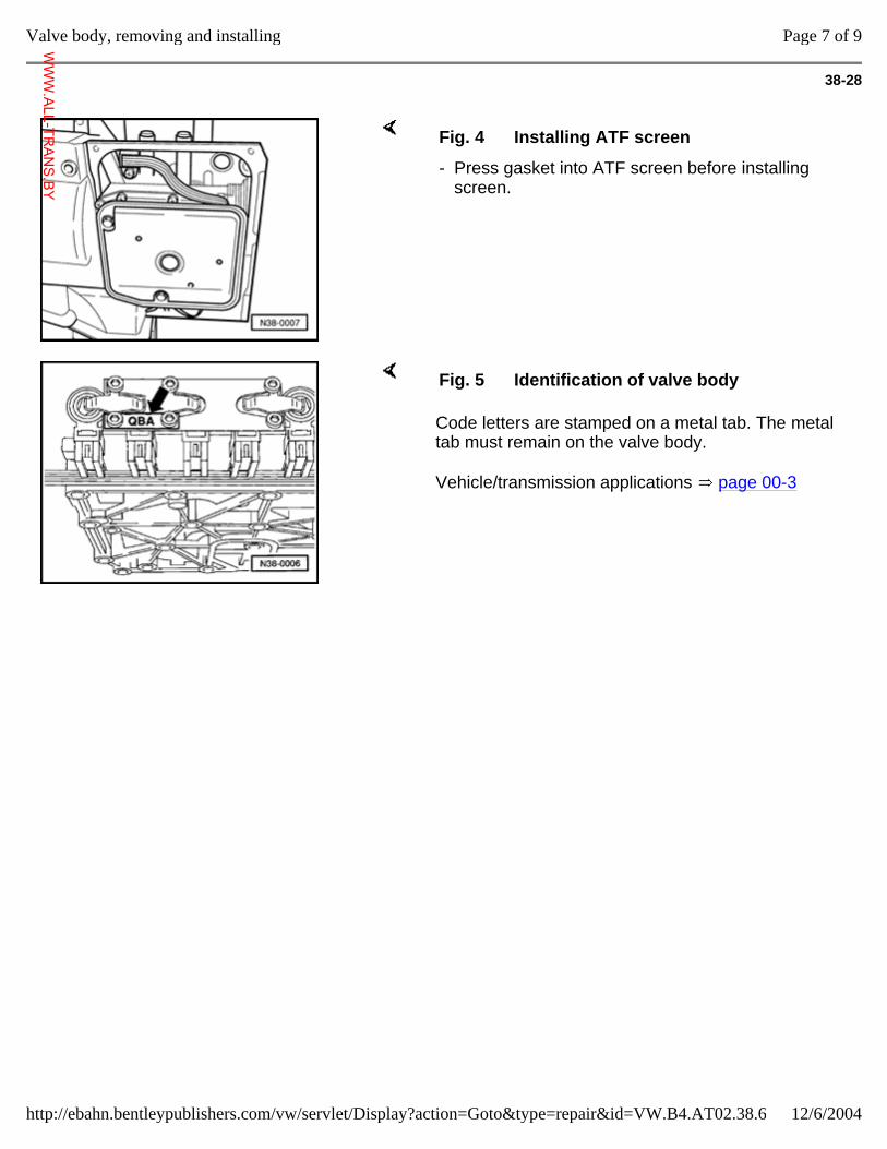
38-28
Fig. 4 Installing ATF screen
- Press gasket into ATF screen before installing screen.
Code letters are stamped on a metal tab. The metal tab must remain on the valve body.
Vehicle/transmission applications page 00-3
Fig. 5 Identification of valve body
Page 7 of 9Valve body, removing and installing
12/6/2004http://ebahn.bentleypublishers.com/vw/servlet/Display?action=Goto&type=repair&id=VW.B4.AT02.38.6
WWW.ALL-TR
ANS.BY
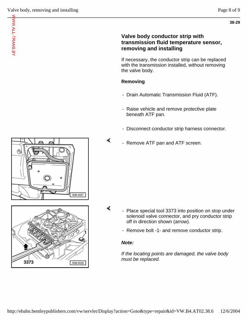
38-29
Valve body conductor strip with transmission fluid temperature sensor, removing and installing
If necessary, the conductor strip can be replaced with the transmission installed, without removing the valve body.
Removing
- Drain Automatic Transmission Fluid (ATF).
- Raise vehicle and remove protective plate beneath ATF pan.
- Disconnect conductor strip harness connector.
- Remove ATF pan and ATF screen.
Note:
If the locating points are damaged, the valve body must be replaced.
- Place special tool 3373 into position on stop under solenoid valve connector, and pry conductor strip off in direction shown (arrow).
- Remove bolt -1- and remove conductor strip.
Page 8 of 9Valve body, removing and installing
12/6/2004http://ebahn.bentleypublishers.com/vw/servlet/Display?action=Goto&type=repair&id=VW.B4.AT02.38.6
WWW.ALL-TR
ANS.BY
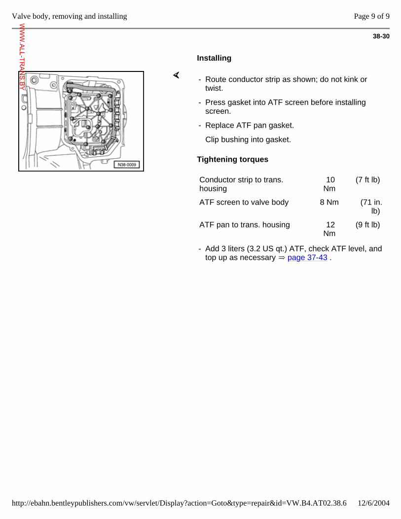
38-30
Installing
Tightening torques
- Route conductor strip as shown; do not kink or twist.
- Press gasket into ATF screen before installing screen.
- Replace ATF pan gasket.
Clip bushing into gasket.
Conductor strip to trans. housing
10 Nm
(7 ft lb)
ATF screen to valve body 8 Nm (71 in. lb)
ATF pan to trans. housing 12 Nm
(9 ft lb)
- Add 3 liters (3.2 US qt.) ATF, check ATF level, and top up as necessary page 37-43 .
Page 9 of 9Valve body, removing and installing
12/6/2004http://ebahn.bentleypublishers.com/vw/servlet/Display?action=Goto&type=repair&id=VW.B4.AT02.38.6
WWW.ALL-TR
ANS.BY
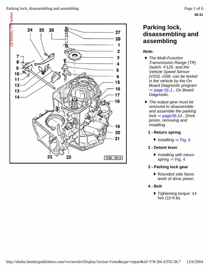
38-31
Parking lock, disassembling and assembling Note:
The Multi-Function Transmission Range (TR) Switch -F125- and the Vehicle Speed Sensor (VSS) -G68- can be tested in the vehicle by the On Board Diagnostic program
page 01-1 , On Board Diagnostic.
The output gear must be removed to disassemble and assemble the parking lock page39-14 , Drive pinion, removing and installing.
1 - Return spring
Installing Fig. 4
2 - Detent lever
Installing with return spring Fig. 4
3 - Parking lock gear
Rounded side faces teeth of drive pinion
4 - Bolt
Tightening torque: 14 Nm (10 ft lb)
Page 1 of 6Parking lock, disassembling and assembling
12/6/2004http://ebahn.bentleypublishers.com/vw/servlet/Display?action=Goto&type=repair&id=VW.B4.AT02.38.7
WWW.ALL-TR
ANS.BY
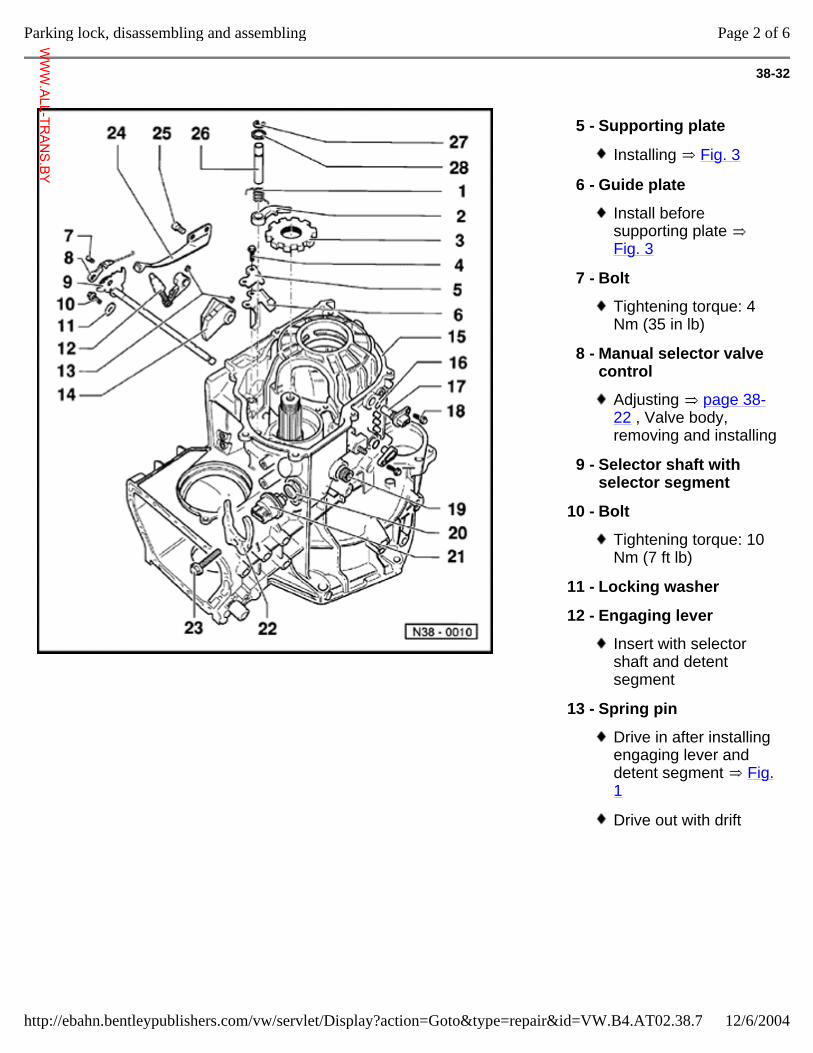
38-32
5 - Supporting plate
Installing Fig. 3
6 - Guide plate
Install before supporting plate Fig. 3
7 - Bolt
Tightening torque: 4 Nm (35 in lb)
8 - Manual selector valve control
Adjusting page 38-22 , Valve body, removing and installing
9 - Selector shaft with selector segment
10 - Bolt
Tightening torque: 10 Nm (7 ft lb)
11 - Locking washer
12 - Engaging lever
Insert with selector shaft and detent segment
13 - Spring pin
Drive in after installing engaging lever and detent segment Fig. 1
Drive out with drift
Page 2 of 6Parking lock, disassembling and assembling
12/6/2004http://ebahn.bentleypublishers.com/vw/servlet/Display?action=Goto&type=repair&id=VW.B4.AT02.38.7
WWW.ALL-TR
ANS.BY
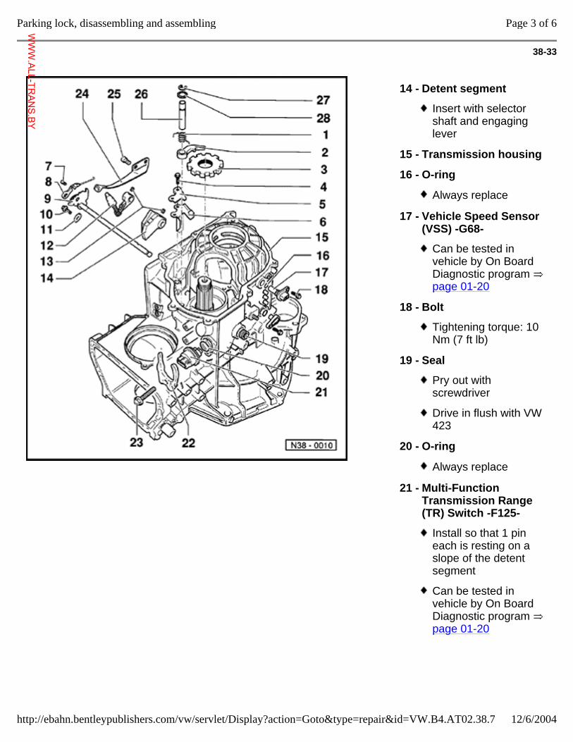
38-33
14 - Detent segment
Insert with selector shaft and engaging lever
15 - Transmission housing
16 - O-ring
Always replace
17 - Vehicle Speed Sensor (VSS) -G68-
Can be tested in vehicle by On Board Diagnostic program page 01-20
18 - Bolt
Tightening torque: 10 Nm (7 ft lb)
19 - Seal
Pry out with screwdriver
Drive in flush with VW 423
20 - O-ring
Always replace
21 - Multi-Function Transmission Range (TR) Switch -F125-
Install so that 1 pin each is resting on a slope of the detent segment
Can be tested in vehicle by On Board Diagnostic program page 01-20
Page 3 of 6Parking lock, disassembling and assembling
12/6/2004http://ebahn.bentleypublishers.com/vw/servlet/Display?action=Goto&type=repair&id=VW.B4.AT02.38.7
WWW.ALL-TR
ANS.BY
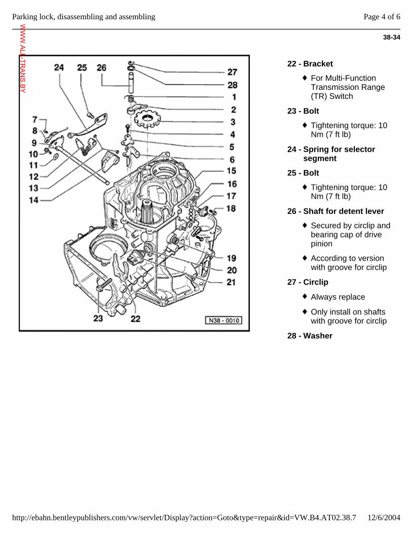
38-34
22 - Bracket
For Multi-Function Transmission Range (TR) Switch
23 - Bolt
Tightening torque: 10 Nm (7 ft lb)
24 - Spring for selector segment
25 - Bolt
Tightening torque: 10 Nm (7 ft lb)
26 - Shaft for detent lever
Secured by circlip and bearing cap of drive pinion
According to version with groove for circlip
27 - Circlip
Always replace
Only install on shafts with groove for circlip
28 - Washer
Page 4 of 6Parking lock, disassembling and assembling
12/6/2004http://ebahn.bentleypublishers.com/vw/servlet/Display?action=Goto&type=repair&id=VW.B4.AT02.38.7
WWW.ALL-TR
ANS.BY
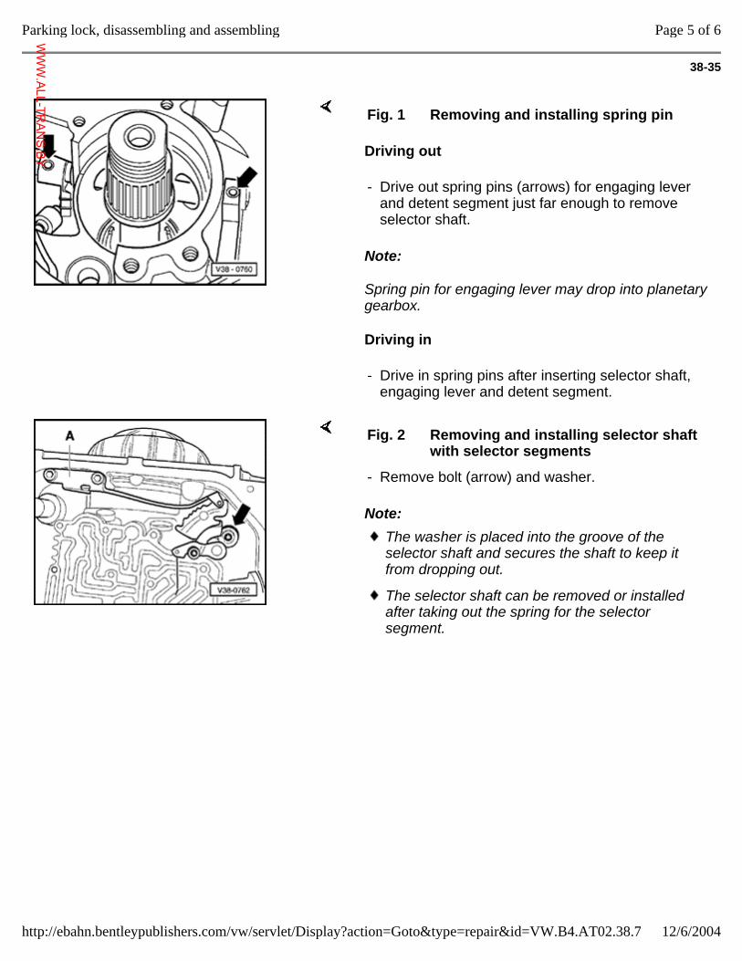
38-35
Driving out
Note:
Spring pin for engaging lever may drop into planetary gearbox.
Driving in
Fig. 1 Removing and installing spring pin
- Drive out spring pins (arrows) for engaging lever and detent segment just far enough to remove selector shaft.
- Drive in spring pins after inserting selector shaft, engaging lever and detent segment.
Note:
Fig. 2 Removing and installing selector shaft with selector segments
- Remove bolt (arrow) and washer.
The washer is placed into the groove of the selector shaft and secures the shaft to keep it from dropping out.
The selector shaft can be removed or installed after taking out the spring for the selector segment.
Page 5 of 6Parking lock, disassembling and assembling
12/6/2004http://ebahn.bentleypublishers.com/vw/servlet/Display?action=Goto&type=repair&id=VW.B4.AT02.38.7
WWW.ALL-TR
ANS.BY
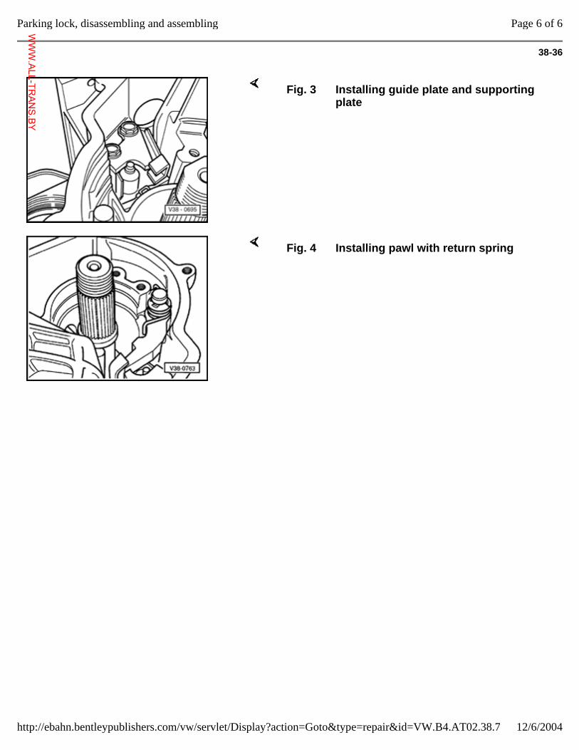
38-36
Fig. 3 Installing guide plate and supporting plate
Fig. 4 Installing pawl with return spring
Page 6 of 6Parking lock, disassembling and assembling
12/6/2004http://ebahn.bentleypublishers.com/vw/servlet/Display?action=Goto&type=repair&id=VW.B4.AT02.38.7
WWW.ALL-TR
ANS.BY
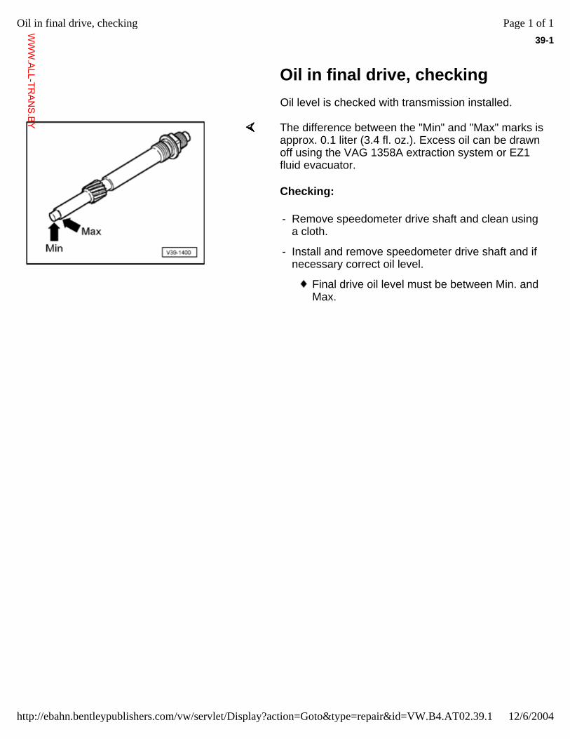
39-1
Oil in final drive, checking Oil level is checked with transmission installed.
The difference between the "Min" and "Max" marks is approx. 0.1 liter (3.4 fl. oz.). Excess oil can be drawn off using the VAG 1358A extraction system or EZ1 fluid evacuator.
Checking:
- Remove speedometer drive shaft and clean using a cloth.
- Install and remove speedometer drive shaft and if necessary correct oil level.
Final drive oil level must be between Min. and Max.
Page 1 of 1Oil in final drive, checking
12/6/2004http://ebahn.bentleypublishers.com/vw/servlet/Display?action=Goto&type=repair&id=VW.B4.AT02.39.1
WWW.ALL-TR
ANS.BY
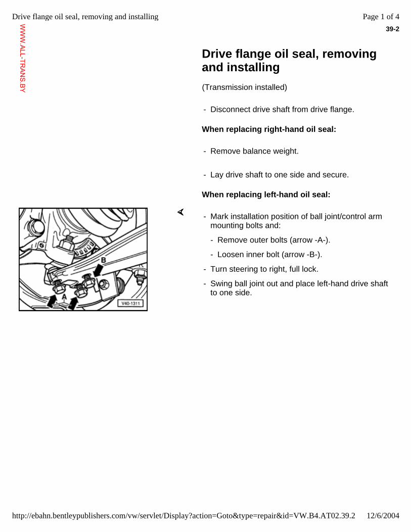
39-2
Drive flange oil seal, removing and installing
(Transmission installed)
- Disconnect drive shaft from drive flange.
When replacing right-hand oil seal:
- Remove balance weight.
- Lay drive shaft to one side and secure.
When replacing left-hand oil seal:
- Mark installation position of ball joint/control arm mounting bolts and:
- Remove outer bolts (arrow -A-).
- Loosen inner bolt (arrow -B-).
- Turn steering to right, full lock.
- Swing ball joint out and place left-hand drive shaft to one side.
Page 1 of 4Drive flange oil seal, removing and installing
12/6/2004http://ebahn.bentleypublishers.com/vw/servlet/Display?action=Goto&type=repair&id=VW.B4.AT02.39.2
WWW.ALL-TR
ANS.BY
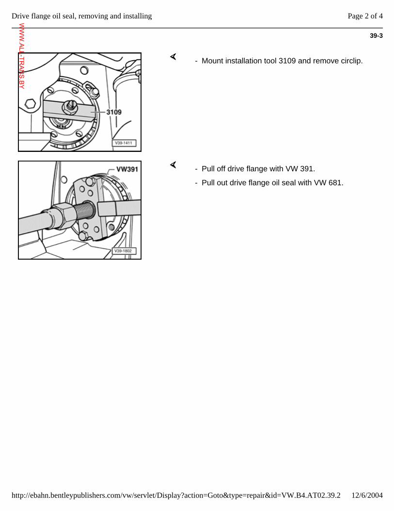
39-3
- Mount installation tool 3109 and remove circlip.
- Pull off drive flange with VW 391.
- Pull out drive flange oil seal with VW 681.
Page 2 of 4Drive flange oil seal, removing and installing
12/6/2004http://ebahn.bentleypublishers.com/vw/servlet/Display?action=Goto&type=repair&id=VW.B4.AT02.39.2
WWW.ALL-TR
ANS.BY
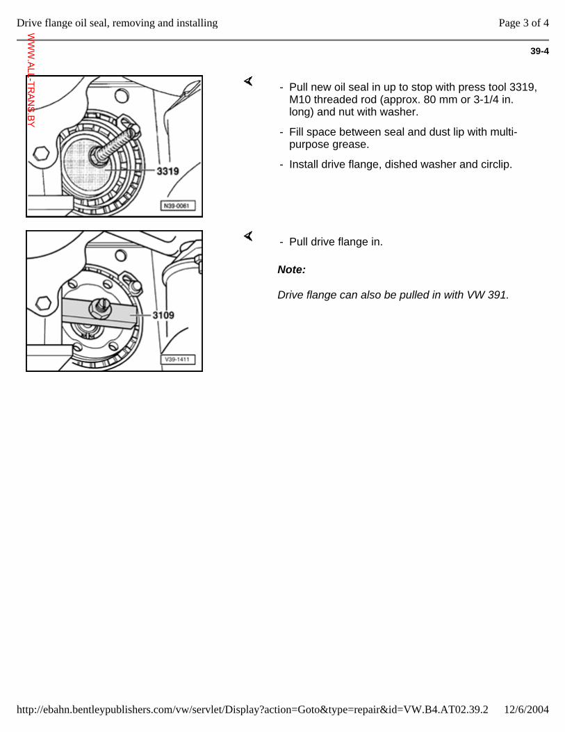
39-4
- Pull new oil seal in up to stop with press tool 3319, M10 threaded rod (approx. 80 mm or 3-1/4 in. long) and nut with washer.
- Fill space between seal and dust lip with multi-purpose grease.
- Install drive flange, dished washer and circlip.
Note:
Drive flange can also be pulled in with VW 391.
- Pull drive flange in.
Page 3 of 4Drive flange oil seal, removing and installing
12/6/2004http://ebahn.bentleypublishers.com/vw/servlet/Display?action=Goto&type=repair&id=VW.B4.AT02.39.2
WWW.ALL-TR
ANS.BY
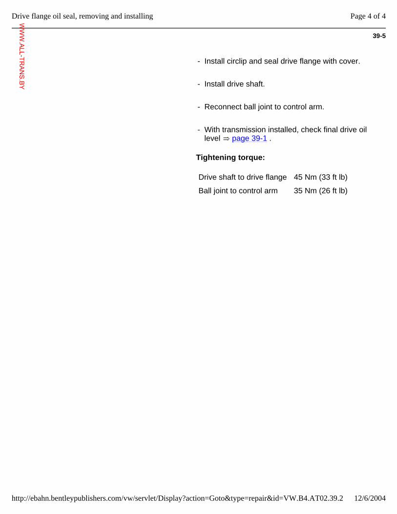
39-5
- Install circlip and seal drive flange with cover.
- Install drive shaft.
- Reconnect ball joint to control arm.
- With transmission installed, check final drive oil level page 39-1 .
Tightening torque:
Drive shaft to drive flange 45 Nm (33 ft lb)
Ball joint to control arm 35 Nm (26 ft lb)
Page 4 of 4Drive flange oil seal, removing and installing
12/6/2004http://ebahn.bentleypublishers.com/vw/servlet/Display?action=Goto&type=repair&id=VW.B4.AT02.39.2
WWW.ALL-TR
ANS.BY
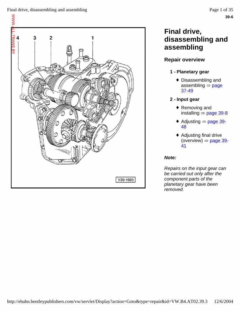
39-6
Final drive, disassembling and assembling Repair overview
Note:
Repairs on the input gear can be carried out only after the component parts of the planetary gear have been removed.
1 - Planetary gear
Disassembling and assembling page 37-49
2 - Input gear
Removing and installing page 39-8
Adjusting page 39-48
Adjusting final drive (overview) page 39-41
Page 1 of 35Final drive, disassembling and assembling
12/6/2004http://ebahn.bentleypublishers.com/vw/servlet/Display?action=Goto&type=repair&id=VW.B4.AT02.39.3
WWW.ALL-TR
ANS.BY
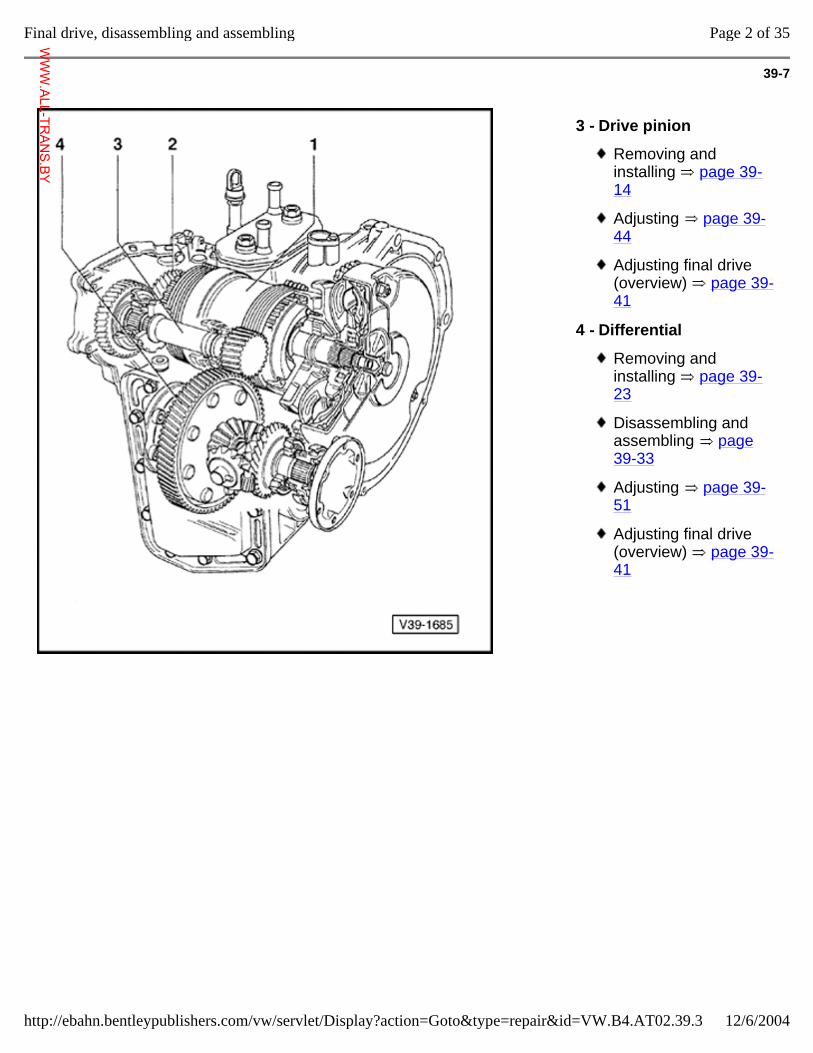
39-7
3 - Drive pinion
Removing and installing page 39-14
Adjusting page 39-44
Adjusting final drive (overview) page 39-41
4 - Differential
Removing and installing page 39-23
Disassembling and assembling page 39-33
Adjusting page 39-51
Adjusting final drive (overview) page 39-41
Page 2 of 35Final drive, disassembling and assembling
12/6/2004http://ebahn.bentleypublishers.com/vw/servlet/Display?action=Goto&type=repair&id=VW.B4.AT02.39.3
WWW.ALL-TR
ANS.BY
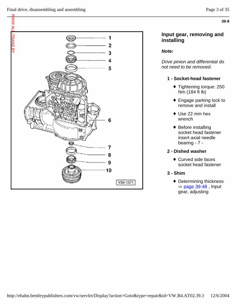
39-8
Input gear, removing and installing
Note:
Drive pinion and differential do not need to be removed.
1 - Socket-head fastener
Tightening torque: 250 Nm (184 ft lb)
Engage parking lock to remove and install
Use 22 mm hex wrench
Before installing socket head fastener insert axial needle bearing - 7 -
2 - Dished washer
Curved side faces socket head fastener
3 - Shim
Determining thickness page 39-48 , Input
gear, adjusting
Page 3 of 35Final drive, disassembling and assembling
12/6/2004http://ebahn.bentleypublishers.com/vw/servlet/Display?action=Goto&type=repair&id=VW.B4.AT02.39.3
WWW.ALL-TR
ANS.BY
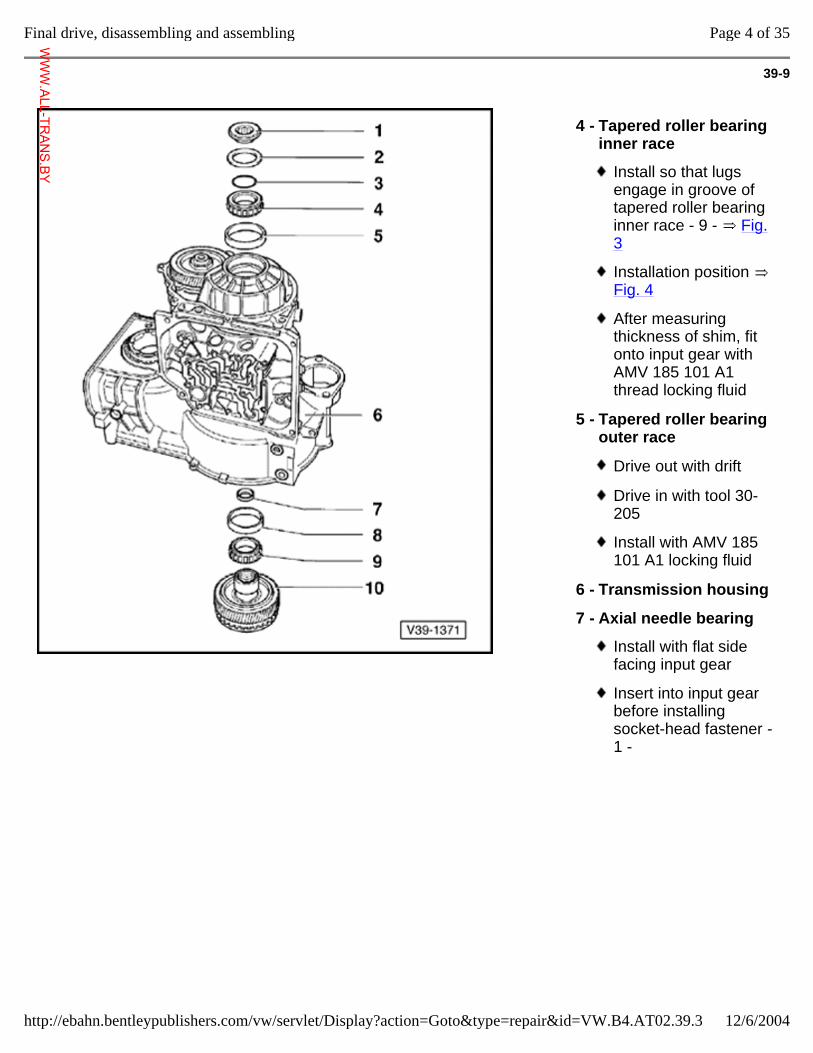
39-9
4 - Tapered roller bearing inner race
Install so that lugs engage in groove of tapered roller bearing inner race - 9 - Fig. 3
Installation position Fig. 4
After measuring thickness of shim, fit onto input gear with AMV 185 101 A1 thread locking fluid
5 - Tapered roller bearing outer race
Drive out with drift
Drive in with tool 30-205
Install with AMV 185 101 A1 locking fluid
6 - Transmission housing
7 - Axial needle bearing
Install with flat side facing input gear
Insert into input gear before installing socket-head fastener - 1 -
Page 4 of 35Final drive, disassembling and assembling
12/6/2004http://ebahn.bentleypublishers.com/vw/servlet/Display?action=Goto&type=repair&id=VW.B4.AT02.39.3
WWW.ALL-TR
ANS.BY
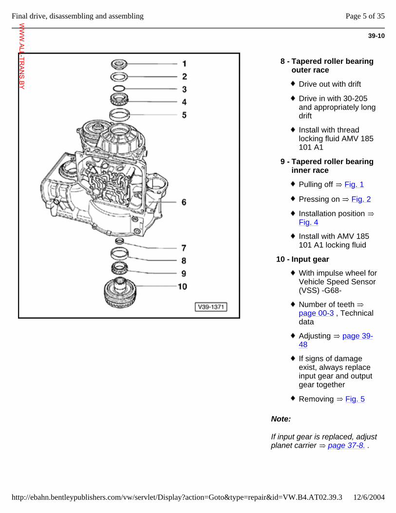
39-10
Note:
If input gear is replaced, adjust planet carrier page 37-8. .
8 - Tapered roller bearing outer race
Drive out with drift
Drive in with 30-205 and appropriately long drift
Install with thread locking fluid AMV 185 101 A1
9 - Tapered roller bearing inner race
Pulling off Fig. 1
Pressing on Fig. 2
Installation position Fig. 4
Install with AMV 185 101 A1 locking fluid
10 - Input gear
With impulse wheel for Vehicle Speed Sensor (VSS) -G68-
Number of teeth page 00-3 , Technical data
Adjusting page 39-48
If signs of damage exist, always replace input gear and output gear together
Removing Fig. 5
Page 5 of 35Final drive, disassembling and assembling
12/6/2004http://ebahn.bentleypublishers.com/vw/servlet/Display?action=Goto&type=repair&id=VW.B4.AT02.39.3
WWW.ALL-TR
ANS.BY
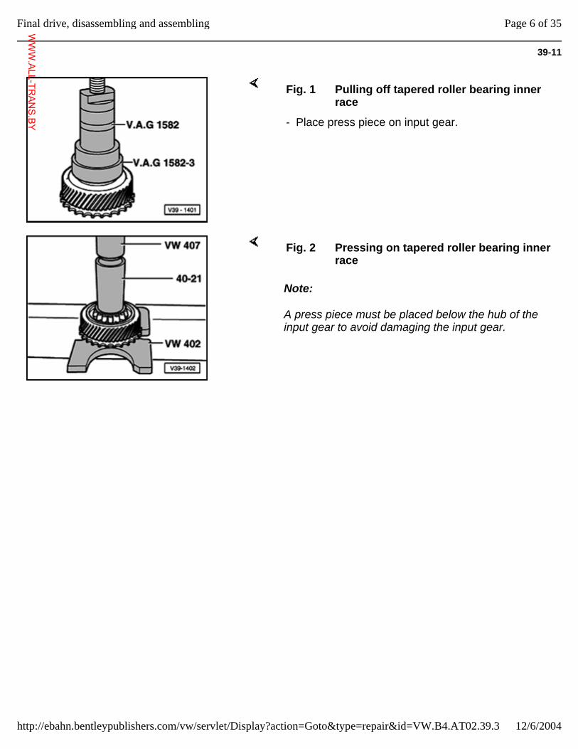
39-11
Fig. 1 Pulling off tapered roller bearing inner race
- Place press piece on input gear.
Note:
A press piece must be placed below the hub of the input gear to avoid damaging the input gear.
Fig. 2 Pressing on tapered roller bearing inner race
Page 6 of 35Final drive, disassembling and assembling
12/6/2004http://ebahn.bentleypublishers.com/vw/servlet/Display?action=Goto&type=repair&id=VW.B4.AT02.39.3
WWW.ALL-TR
ANS.BY
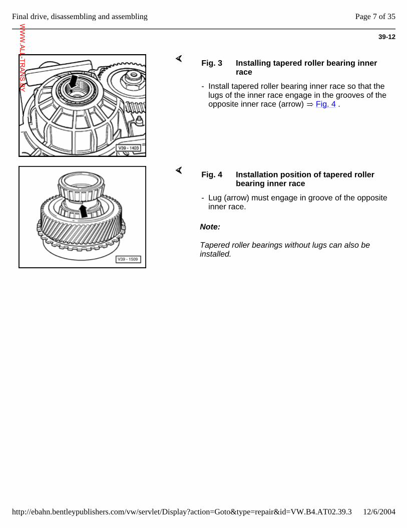
39-12
Fig. 3 Installing tapered roller bearing inner race
- Install tapered roller bearing inner race so that the lugs of the inner race engage in the grooves of the opposite inner race (arrow) Fig. 4 .
Note:
Tapered roller bearings without lugs can also be installed.
Fig. 4 Installation position of tapered roller bearing inner race
- Lug (arrow) must engage in groove of the opposite inner race.
Page 7 of 35Final drive, disassembling and assembling
12/6/2004http://ebahn.bentleypublishers.com/vw/servlet/Display?action=Goto&type=repair&id=VW.B4.AT02.39.3
WWW.ALL-TR
ANS.BY
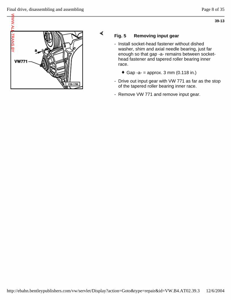
39-13
Fig. 5 Removing input gear
- Install socket-head fastener without dished washer, shim and axial needle bearing, just far enough so that gap -a- remains between socket-head fastener and tapered roller bearing inner race.
Gap -a- = approx. 3 mm (0.118 in.)
- Drive out input gear with VW 771 as far as the stop of the tapered roller bearing inner race.
- Remove VW 771 and remove input gear.
Page 8 of 35Final drive, disassembling and assembling
12/6/2004http://ebahn.bentleypublishers.com/vw/servlet/Display?action=Goto&type=repair&id=VW.B4.AT02.39.3
WWW.ALL-TR
ANS.BY
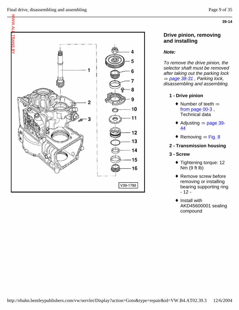
39-14
Drive pinion, removing and installing
Note:
To remove the drive pinion, the selector shaft must be removed after taking out the parking lock
page 38-31 , Parking lock, disassembling and assembling.
1 - Drive pinion
Number of teeth from page 00-3 , Technical data
Adjusting page 39-44
Removing Fig. 8
2 - Transmission housing
3 - Screw
Tightening torque: 12 Nm (9 ft lb)
Remove screw before removing or installing bearing supporting ring - 12 -
Install with AKD45600001 sealing compound
Page 9 of 35Final drive, disassembling and assembling
12/6/2004http://ebahn.bentleypublishers.com/vw/servlet/Display?action=Goto&type=repair&id=VW.B4.AT02.39.3
WWW.ALL-TR
ANS.BY
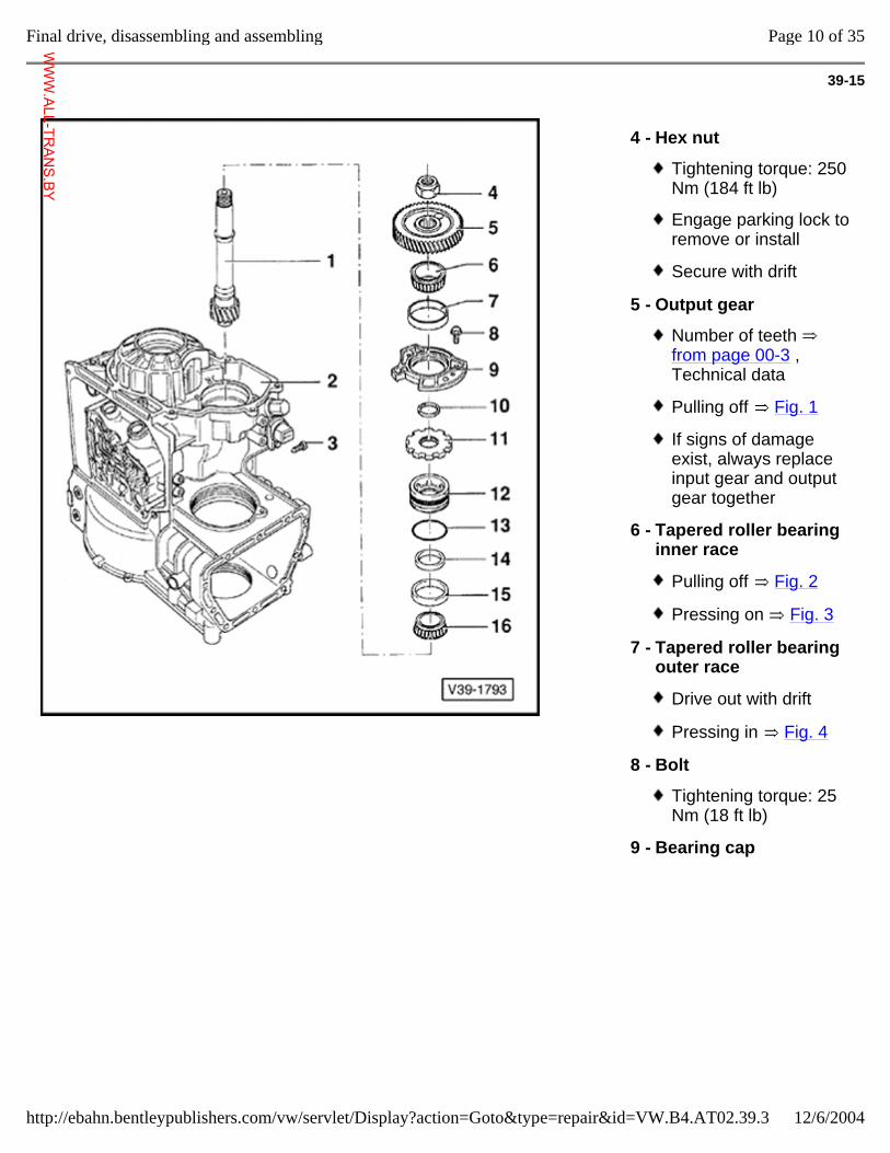
39-15
4 - Hex nut
Tightening torque: 250 Nm (184 ft lb)
Engage parking lock to remove or install
Secure with drift
5 - Output gear
Number of teeth from page 00-3 , Technical data
Pulling off Fig. 1
If signs of damage exist, always replace input gear and output gear together
6 - Tapered roller bearing inner race
Pulling off Fig. 2
Pressing on Fig. 3
7 - Tapered roller bearing outer race
Drive out with drift
Pressing in Fig. 4
8 - Bolt
Tightening torque: 25 Nm (18 ft lb)
9 - Bearing cap
Page 10 of 35Final drive, disassembling and assembling
12/6/2004http://ebahn.bentleypublishers.com/vw/servlet/Display?action=Goto&type=repair&id=VW.B4.AT02.39.3
WWW.ALL-TR
ANS.BY
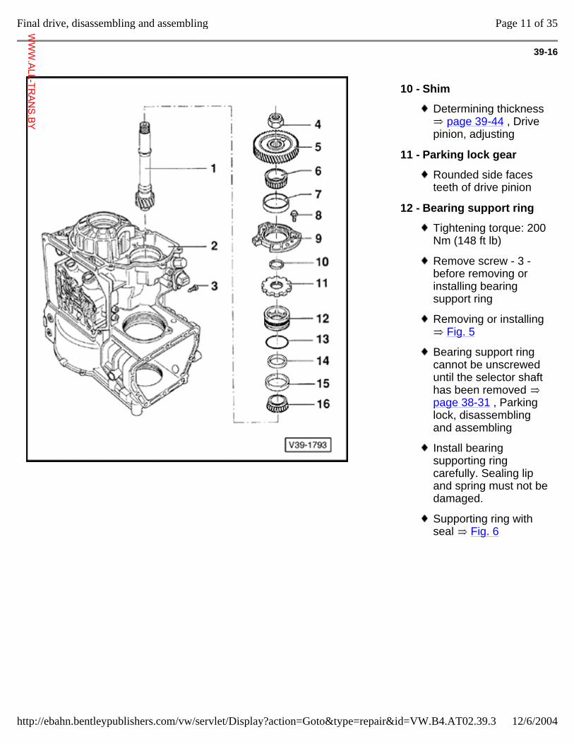
39-16
10 - Shim
Determining thickness page 39-44 , Drive
pinion, adjusting
11 - Parking lock gear
Rounded side faces teeth of drive pinion
12 - Bearing support ring
Tightening torque: 200 Nm (148 ft lb)
Remove screw - 3 - before removing or installing bearing support ring
Removing or installing Fig. 5
Bearing support ring cannot be unscrewed until the selector shaft has been removed page 38-31 , Parking lock, disassembling and assembling
Install bearing supporting ring carefully. Sealing lip and spring must not be damaged.
Supporting ring with seal Fig. 6
Page 11 of 35Final drive, disassembling and assembling
12/6/2004http://ebahn.bentleypublishers.com/vw/servlet/Display?action=Goto&type=repair&id=VW.B4.AT02.39.3
WWW.ALL-TR
ANS.BY
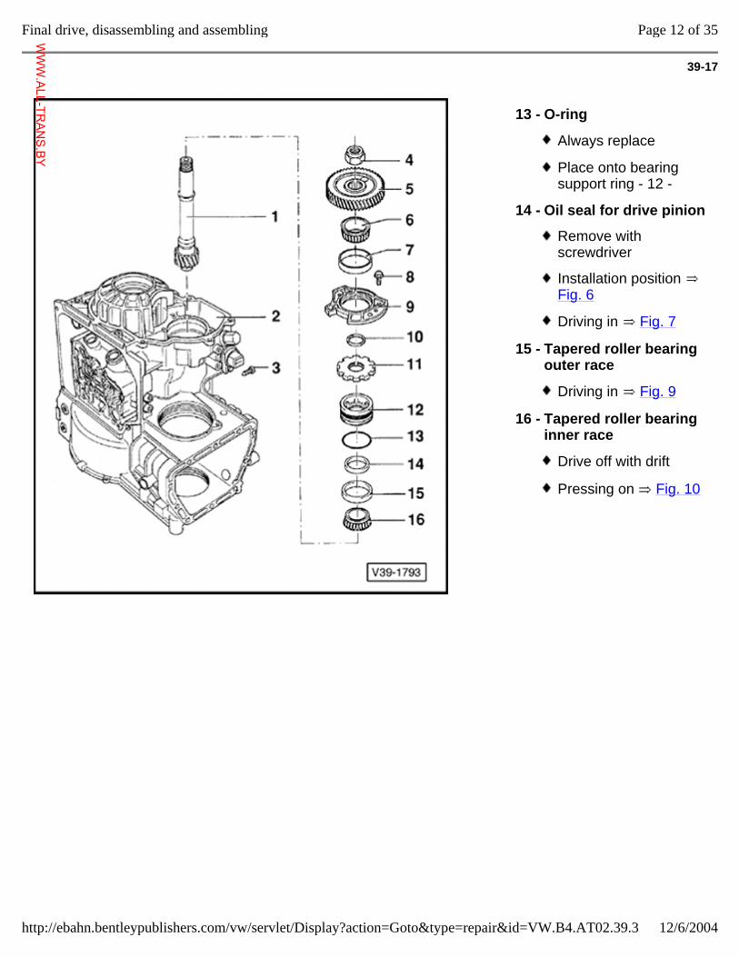
39-17
13 - O-ring
Always replace
Place onto bearing support ring - 12 -
14 - Oil seal for drive pinion
Remove with screwdriver
Installation position Fig. 6
Driving in Fig. 7
15 - Tapered roller bearing outer race
Driving in Fig. 9
16 - Tapered roller bearing inner race
Drive off with drift
Pressing on Fig. 10
Page 12 of 35Final drive, disassembling and assembling
12/6/2004http://ebahn.bentleypublishers.com/vw/servlet/Display?action=Goto&type=repair&id=VW.B4.AT02.39.3
WWW.ALL-TR
ANS.BY
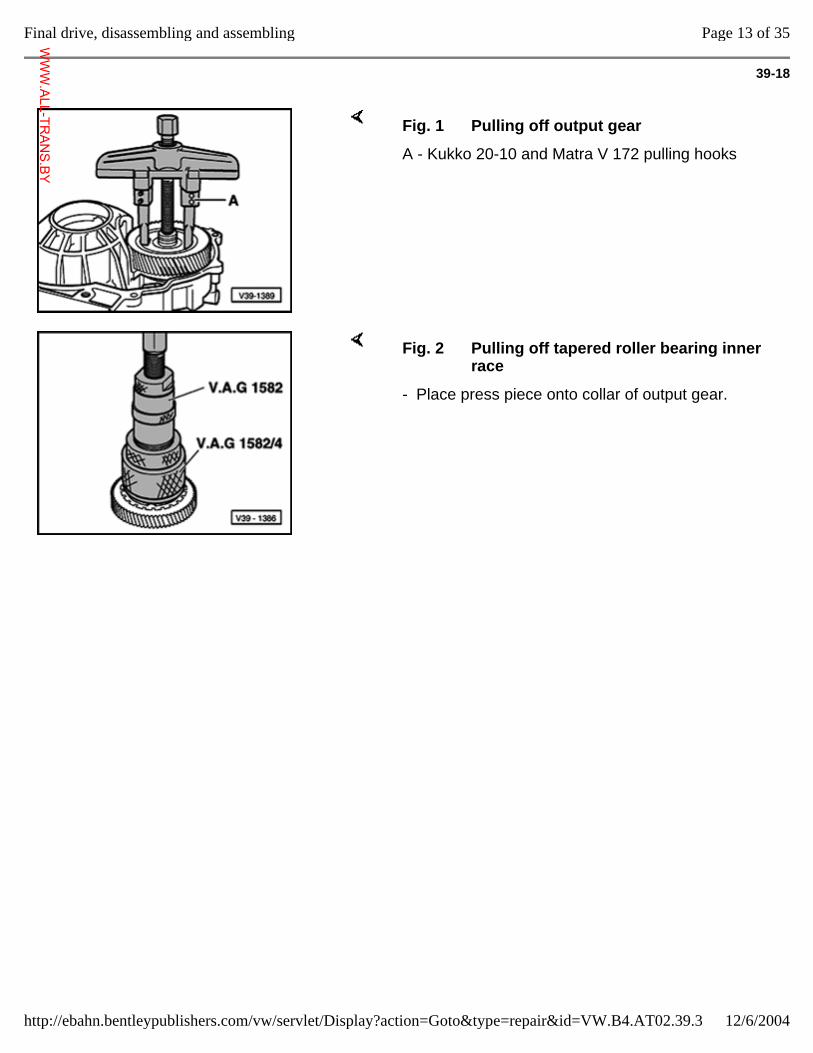
39-18
Fig. 1 Pulling off output gear
A - Kukko 20-10 and Matra V 172 pulling hooks
Fig. 2 Pulling off tapered roller bearing inner race
- Place press piece onto collar of output gear.
Page 13 of 35Final drive, disassembling and assembling
12/6/2004http://ebahn.bentleypublishers.com/vw/servlet/Display?action=Goto&type=repair&id=VW.B4.AT02.39.3
WWW.ALL-TR
ANS.BY
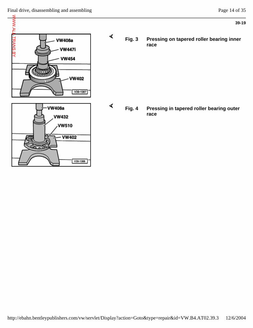
39-19
Fig. 3 Pressing on tapered roller bearing inner race
Fig. 4 Pressing in tapered roller bearing outer race
Page 14 of 35Final drive, disassembling and assembling
12/6/2004http://ebahn.bentleypublishers.com/vw/servlet/Display?action=Goto&type=repair&id=VW.B4.AT02.39.3
WWW.ALL-TR
ANS.BY
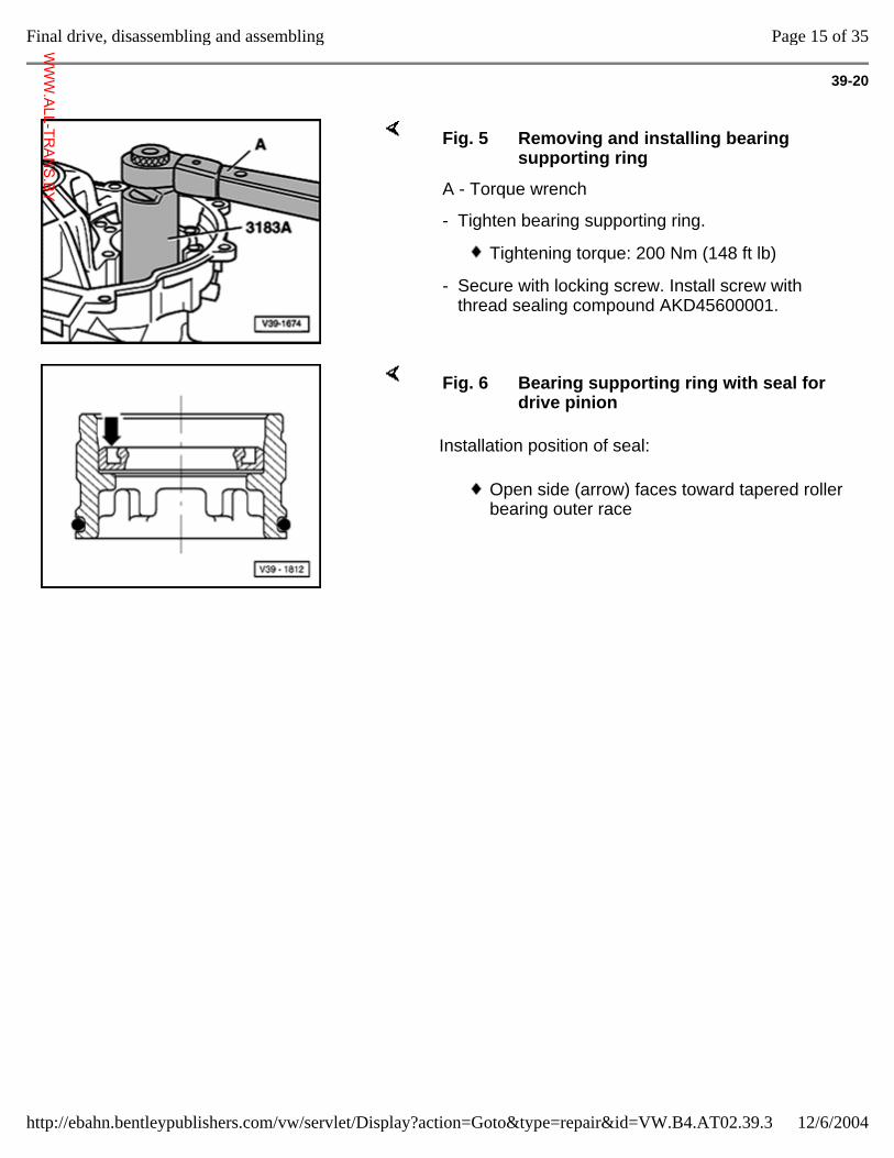
39-20
Fig. 5 Removing and installing bearing supporting ring
A - Torque wrench
- Tighten bearing supporting ring.
Tightening torque: 200 Nm (148 ft lb)
- Secure with locking screw. Install screw with thread sealing compound AKD45600001.
Installation position of seal:
Fig. 6 Bearing supporting ring with seal for drive pinion
Open side (arrow) faces toward tapered roller bearing outer race
Page 15 of 35Final drive, disassembling and assembling
12/6/2004http://ebahn.bentleypublishers.com/vw/servlet/Display?action=Goto&type=repair&id=VW.B4.AT02.39.3
WWW.ALL-TR
ANS.BY
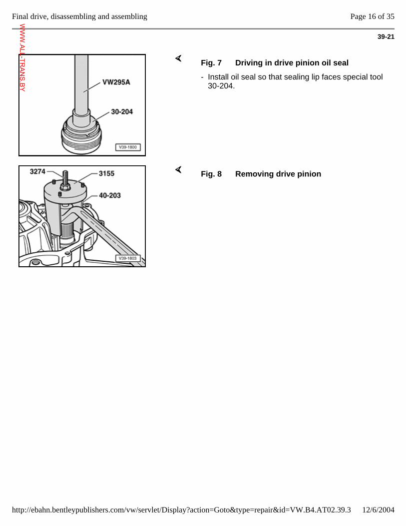
39-21
Fig. 7 Driving in drive pinion oil seal
- Install oil seal so that sealing lip faces special tool 30-204.
Fig. 8 Removing drive pinion
Page 16 of 35Final drive, disassembling and assembling
12/6/2004http://ebahn.bentleypublishers.com/vw/servlet/Display?action=Goto&type=repair&id=VW.B4.AT02.39.3
WWW.ALL-TR
ANS.BY
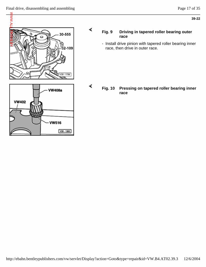
39-22
Fig. 9 Driving in tapered roller bearing outer race
- Install drive pinion with tapered roller bearing inner race, then drive in outer race.
Fig. 10 Pressing on tapered roller bearing inner race
Page 17 of 35Final drive, disassembling and assembling
12/6/2004http://ebahn.bentleypublishers.com/vw/servlet/Display?action=Goto&type=repair&id=VW.B4.AT02.39.3
WWW.ALL-TR
ANS.BY
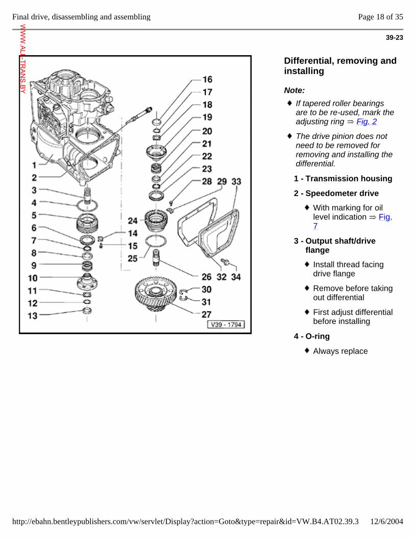
39-23
Differential, removing and installing
Note: If tapered roller bearings are to be re-used, mark the adjusting ring Fig. 2
The drive pinion does not need to be removed for removing and installing the differential.
1 - Transmission housing
2 - Speedometer drive
With marking for oil level indication Fig. 7
3 - Output shaft/drive flange
Install thread facing drive flange
Remove before taking out differential
First adjust differential before installing
4 - O-ring
Always replace
Page 18 of 35Final drive, disassembling and assembling
12/6/2004http://ebahn.bentleypublishers.com/vw/servlet/Display?action=Goto&type=repair&id=VW.B4.AT02.39.3
WWW.ALL-TR
ANS.BY
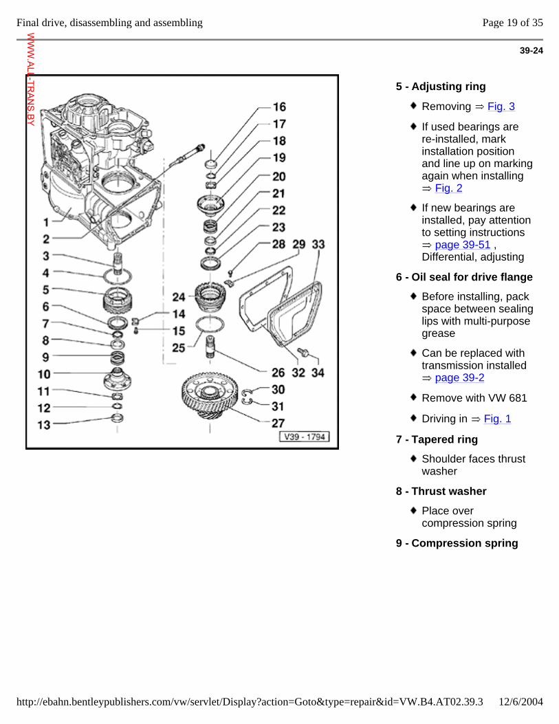
39-24
5 - Adjusting ring
Removing Fig. 3
If used bearings are re-installed, mark installation position and line up on marking again when installing
Fig. 2
If new bearings are installed, pay attention to setting instructions
page 39-51 , Differential, adjusting
6 - Oil seal for drive flange
Before installing, pack space between sealing lips with multi-purpose grease
Can be replaced with transmission installed
page 39-2
Remove with VW 681
Driving in Fig. 1
7 - Tapered ring
Shoulder faces thrust washer
8 - Thrust washer
Place over compression spring
9 - Compression spring
Page 19 of 35Final drive, disassembling and assembling
12/6/2004http://ebahn.bentleypublishers.com/vw/servlet/Display?action=Goto&type=repair&id=VW.B4.AT02.39.3
WWW.ALL-TR
ANS.BY
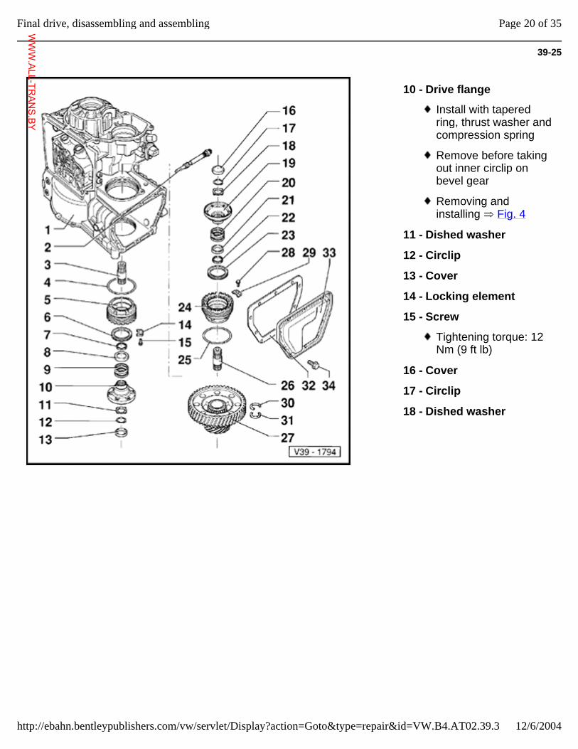
39-25
10 - Drive flange
Install with tapered ring, thrust washer and compression spring
Remove before taking out inner circlip on bevel gear
Removing and installing Fig. 4
11 - Dished washer
12 - Circlip
13 - Cover
14 - Locking element
15 - Screw
Tightening torque: 12 Nm (9 ft lb)
16 - Cover
17 - Circlip
18 - Dished washer
Page 20 of 35Final drive, disassembling and assembling
12/6/2004http://ebahn.bentleypublishers.com/vw/servlet/Display?action=Goto&type=repair&id=VW.B4.AT02.39.3
WWW.ALL-TR
ANS.BY
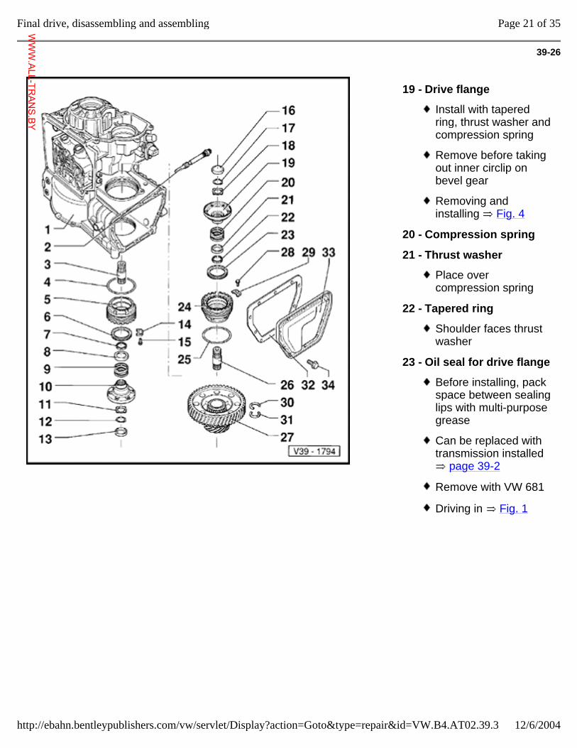
39-26
19 - Drive flange
Install with tapered ring, thrust washer and compression spring
Remove before taking out inner circlip on bevel gear
Removing and installing Fig. 4
20 - Compression spring
21 - Thrust washer
Place over compression spring
22 - Tapered ring
Shoulder faces thrust washer
23 - Oil seal for drive flange
Before installing, pack space between sealing lips with multi-purpose grease
Can be replaced with transmission installed
page 39-2
Remove with VW 681
Driving in Fig. 1
Page 21 of 35Final drive, disassembling and assembling
12/6/2004http://ebahn.bentleypublishers.com/vw/servlet/Display?action=Goto&type=repair&id=VW.B4.AT02.39.3
WWW.ALL-TR
ANS.BY
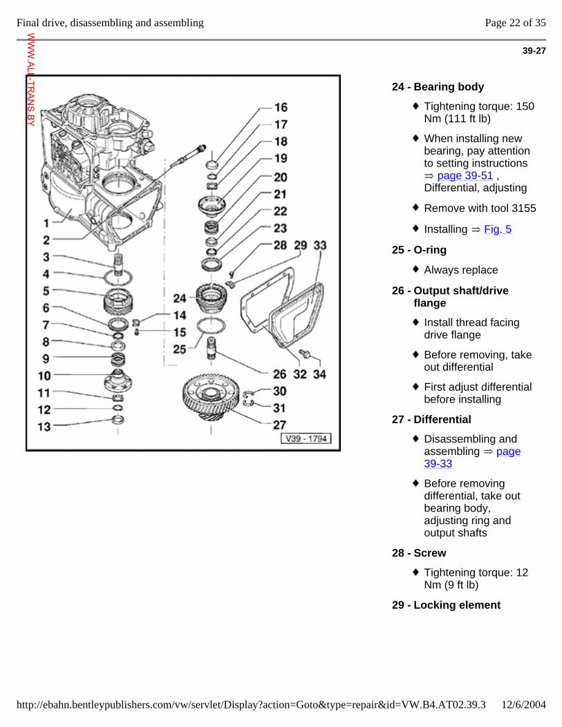
39-27
24 - Bearing body
Tightening torque: 150 Nm (111 ft lb)
When installing new bearing, pay attention to setting instructions
page 39-51 , Differential, adjusting
Remove with tool 3155
Installing Fig. 5
25 - O-ring
Always replace
26 - Output shaft/drive flange
Install thread facing drive flange
Before removing, take out differential
First adjust differential before installing
27 - Differential
Disassembling and assembling page 39-33
Before removing differential, take out bearing body, adjusting ring and output shafts
28 - Screw
Tightening torque: 12 Nm (9 ft lb)
29 - Locking element
Page 22 of 35Final drive, disassembling and assembling
12/6/2004http://ebahn.bentleypublishers.com/vw/servlet/Display?action=Goto&type=repair&id=VW.B4.AT02.39.3
WWW.ALL-TR
ANS.BY
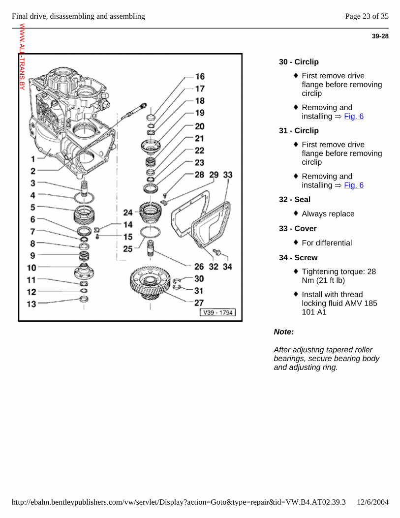
39-28
Note:
After adjusting tapered roller bearings, secure bearing body and adjusting ring.
30 - Circlip
First remove drive flange before removing circlip
Removing and installing Fig. 6
31 - Circlip
First remove drive flange before removing circlip
Removing and installing Fig. 6
32 - Seal
Always replace
33 - Cover
For differential
34 - Screw
Tightening torque: 28 Nm (21 ft lb)
Install with thread locking fluid AMV 185 101 A1
Page 23 of 35Final drive, disassembling and assembling
12/6/2004http://ebahn.bentleypublishers.com/vw/servlet/Display?action=Goto&type=repair&id=VW.B4.AT02.39.3
WWW.ALL-TR
ANS.BY
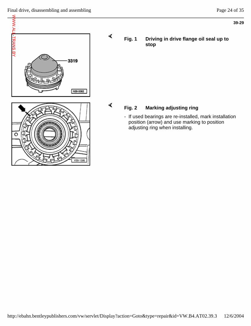
39-29
Fig. 1 Driving in drive flange oil seal up to stop
Fig. 2 Marking adjusting ring
- If used bearings are re-installed, mark installation position (arrow) and use marking to position adjusting ring when installing.
Page 24 of 35Final drive, disassembling and assembling
12/6/2004http://ebahn.bentleypublishers.com/vw/servlet/Display?action=Goto&type=repair&id=VW.B4.AT02.39.3
WWW.ALL-TR
ANS.BY
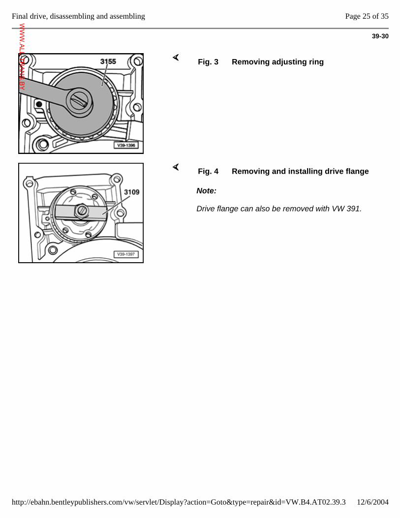
39-30
Fig. 3 Removing adjusting ring
Note:
Drive flange can also be removed with VW 391.
Fig. 4 Removing and installing drive flange
Page 25 of 35Final drive, disassembling and assembling
12/6/2004http://ebahn.bentleypublishers.com/vw/servlet/Display?action=Goto&type=repair&id=VW.B4.AT02.39.3
WWW.ALL-TR
ANS.BY
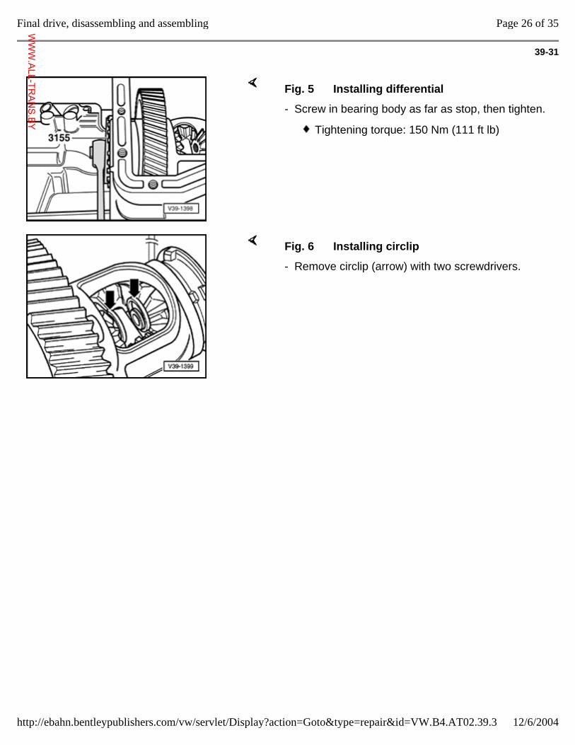
39-31
Fig. 5 Installing differential
- Screw in bearing body as far as stop, then tighten.
Tightening torque: 150 Nm (111 ft lb)
Fig. 6 Installing circlip
- Remove circlip (arrow) with two screwdrivers.
Page 26 of 35Final drive, disassembling and assembling
12/6/2004http://ebahn.bentleypublishers.com/vw/servlet/Display?action=Goto&type=repair&id=VW.B4.AT02.39.3
WWW.ALL-TR
ANS.BY
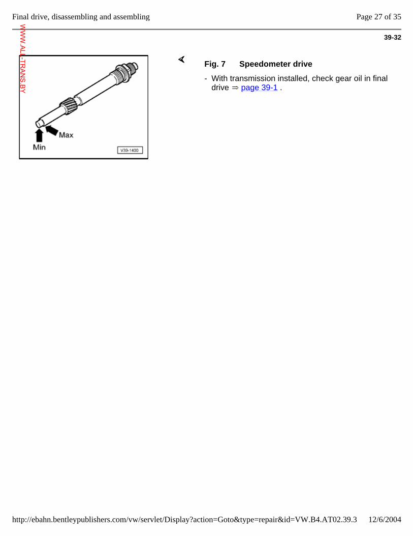
39-32
Fig. 7 Speedometer drive
- With transmission installed, check gear oil in final drive page 39-1 .
Page 27 of 35Final drive, disassembling and assembling
12/6/2004http://ebahn.bentleypublishers.com/vw/servlet/Display?action=Goto&type=repair&id=VW.B4.AT02.39.3
WWW.ALL-TR
ANS.BY
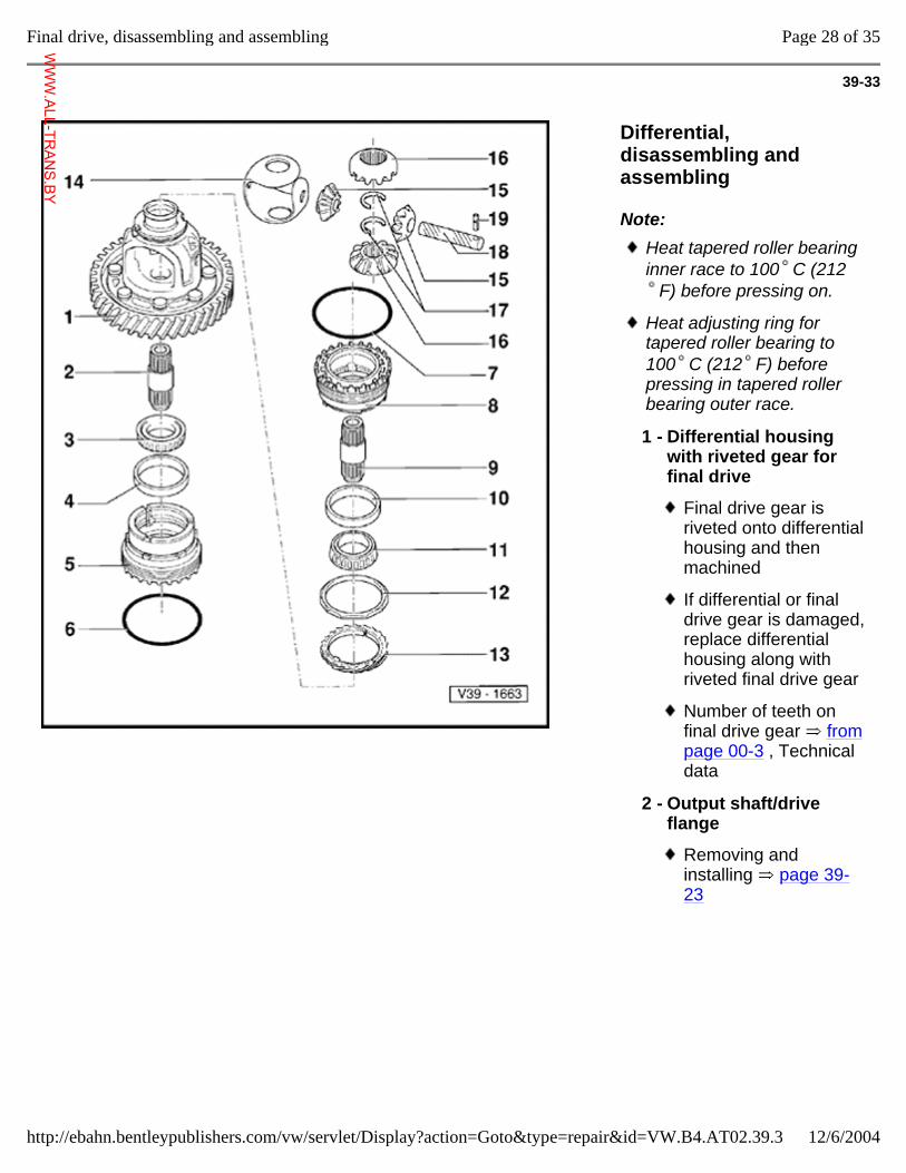
39-33
Differential, disassembling and assembling
Note: Heat tapered roller bearing inner race to 100 C (212
F) before pressing on.
Heat adjusting ring for tapered roller bearing to 100 C (212 F) before pressing in tapered roller bearing outer race.
1 - Differential housing with riveted gear for final drive
Final drive gear is riveted onto differential housing and then machined
If differential or final drive gear is damaged, replace differential housing along with riveted final drive gear
Number of teeth on final drive gear from page 00-3 , Technical data
2 - Output shaft/drive flange
Removing and installing page 39-23
Page 28 of 35Final drive, disassembling and assembling
12/6/2004http://ebahn.bentleypublishers.com/vw/servlet/Display?action=Goto&type=repair&id=VW.B4.AT02.39.3
WWW.ALL-TR
ANS.BY
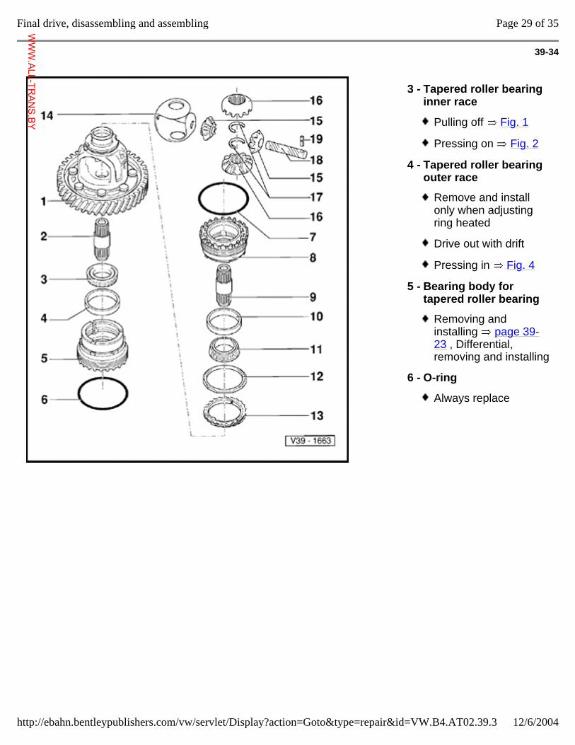
39-34
3 - Tapered roller bearing inner race
Pulling off Fig. 1
Pressing on Fig. 2
4 - Tapered roller bearing outer race
Remove and install only when adjusting ring heated
Drive out with drift
Pressing in Fig. 4
5 - Bearing body for tapered roller bearing
Removing and installing page 39-23 , Differential, removing and installing
6 - O-ring
Always replace
Page 29 of 35Final drive, disassembling and assembling
12/6/2004http://ebahn.bentleypublishers.com/vw/servlet/Display?action=Goto&type=repair&id=VW.B4.AT02.39.3
WWW.ALL-TR
ANS.BY
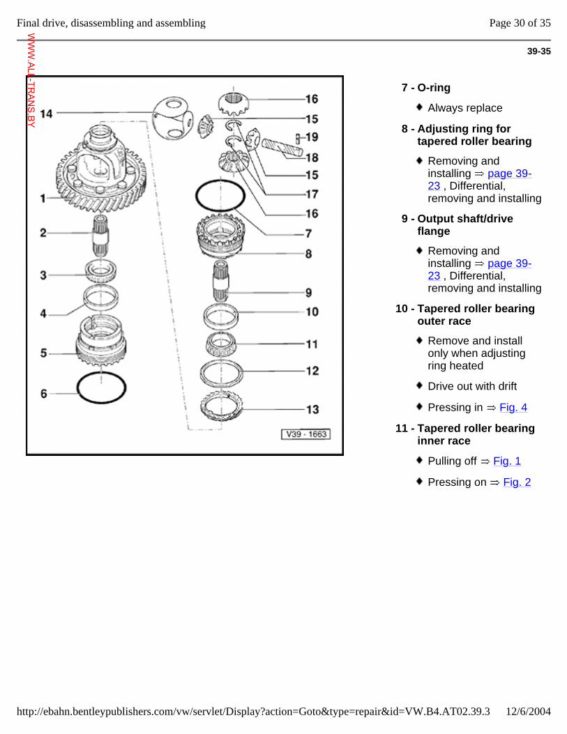
39-35
7 - O-ring
Always replace
8 - Adjusting ring for tapered roller bearing
Removing and installing page 39-23 , Differential, removing and installing
9 - Output shaft/drive flange
Removing and installing page 39-23 , Differential, removing and installing
10 - Tapered roller bearing outer race
Remove and install only when adjusting ring heated
Drive out with drift
Pressing in Fig. 4
11 - Tapered roller bearing inner race
Pulling off Fig. 1
Pressing on Fig. 2
Page 30 of 35Final drive, disassembling and assembling
12/6/2004http://ebahn.bentleypublishers.com/vw/servlet/Display?action=Goto&type=repair&id=VW.B4.AT02.39.3
WWW.ALL-TR
ANS.BY
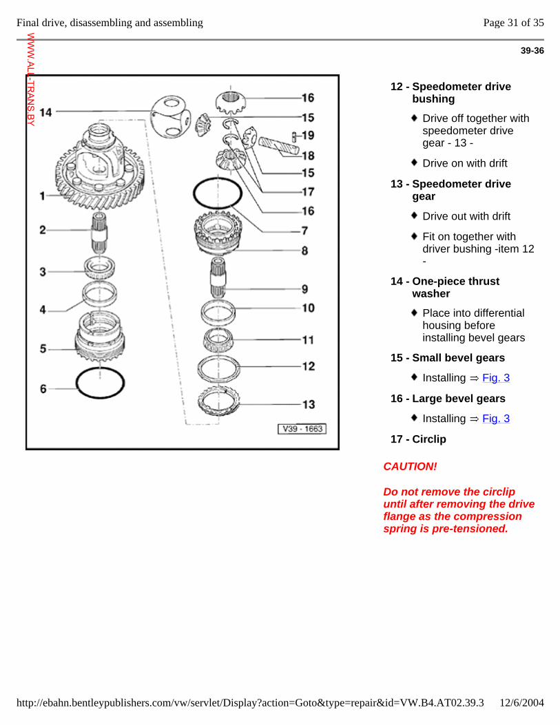
39-36
CAUTION!
Do not remove the circlip until after removing the drive flange as the compression spring is pre-tensioned.
12 - Speedometer drive bushing
Drive off together with speedometer drive gear - 13 -
Drive on with drift
13 - Speedometer drive gear
Drive out with drift
Fit on together with driver bushing -item 12 -
14 - One-piece thrust washer
Place into differential housing before installing bevel gears
15 - Small bevel gears
Installing Fig. 3
16 - Large bevel gears
Installing Fig. 3
17 - Circlip
Page 31 of 35Final drive, disassembling and assembling
12/6/2004http://ebahn.bentleypublishers.com/vw/servlet/Display?action=Goto&type=repair&id=VW.B4.AT02.39.3
WWW.ALL-TR
ANS.BY
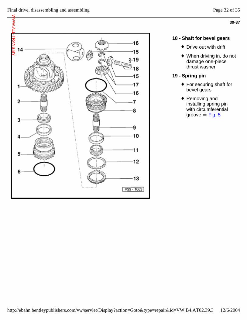
39-37
18 - Shaft for bevel gears
Drive out with drift
When driving in, do not damage one-piece thrust washer
19 - Spring pin
For securing shaft for bevel gears
Removing and installing spring pin with circumferential groove Fig. 5
Page 32 of 35Final drive, disassembling and assembling
12/6/2004http://ebahn.bentleypublishers.com/vw/servlet/Display?action=Goto&type=repair&id=VW.B4.AT02.39.3
WWW.ALL-TR
ANS.BY
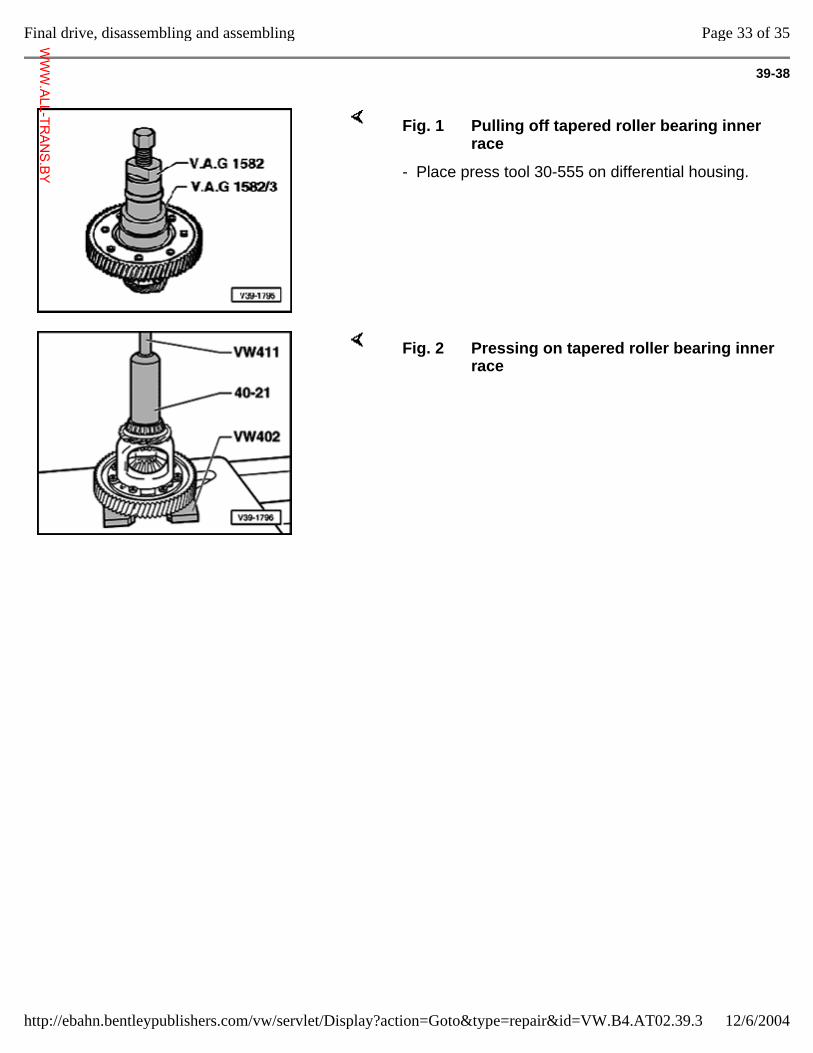
39-38
Fig. 1 Pulling off tapered roller bearing inner race
- Place press tool 30-555 on differential housing.
Fig. 2 Pressing on tapered roller bearing inner race
Page 33 of 35Final drive, disassembling and assembling
12/6/2004http://ebahn.bentleypublishers.com/vw/servlet/Display?action=Goto&type=repair&id=VW.B4.AT02.39.3
WWW.ALL-TR
ANS.BY
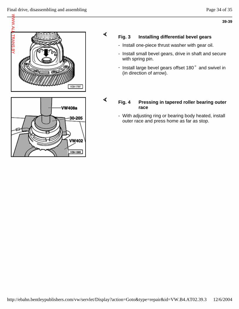
39-39
Fig. 3 Installing differential bevel gears
- Install one-piece thrust washer with gear oil.
- Install small bevel gears, drive in shaft and secure with spring pin.
- Install large bevel gears offset 180 and swivel in (in direction of arrow).
Fig. 4 Pressing in tapered roller bearing outer race
- With adjusting ring or bearing body heated, install outer race and press home as far as stop.
Page 34 of 35Final drive, disassembling and assembling
12/6/2004http://ebahn.bentleypublishers.com/vw/servlet/Display?action=Goto&type=repair&id=VW.B4.AT02.39.3
WWW.ALL-TR
ANS.BY
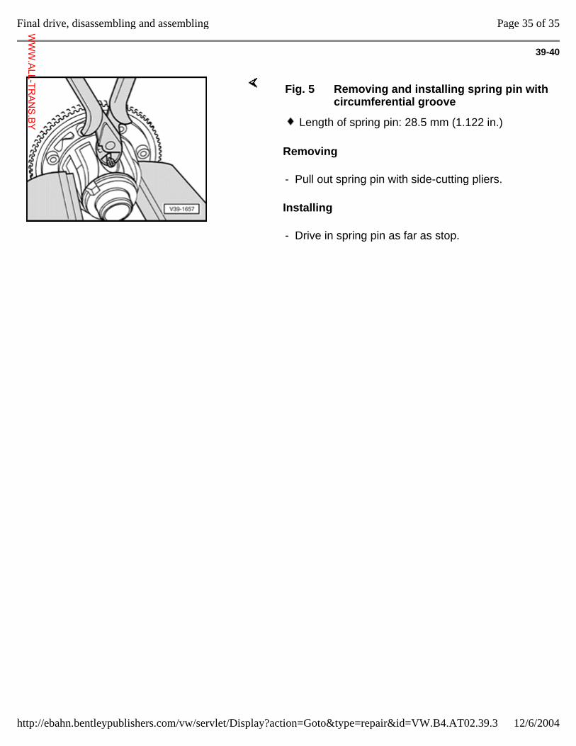
39-40
Removing
Installing
Fig. 5 Removing and installing spring pin with circumferential groove
Length of spring pin: 28.5 mm (1.122 in.)
- Pull out spring pin with side-cutting pliers.
- Drive in spring pin as far as stop.
Page 35 of 35Final drive, disassembling and assembling
12/6/2004http://ebahn.bentleypublishers.com/vw/servlet/Display?action=Goto&type=repair&id=VW.B4.AT02.39.3
WWW.ALL-TR
ANS.BY
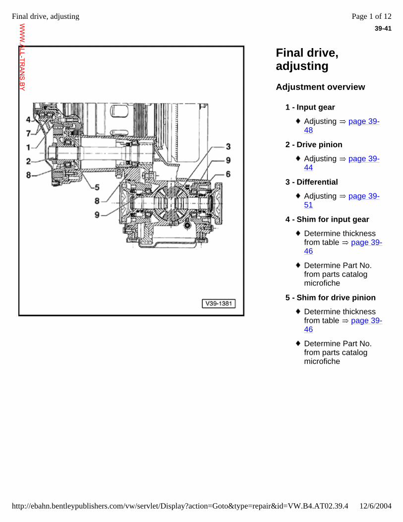
39-41
Final drive, adjusting Adjustment overview
1 - Input gear
Adjusting page 39-48
2 - Drive pinion
Adjusting page 39-44
3 - Differential
Adjusting page 39-51
4 - Shim for input gear
Determine thickness from table page 39-46
Determine Part No. from parts catalog microfiche
5 - Shim for drive pinion
Determine thickness from table page 39-46
Determine Part No. from parts catalog microfiche
Page 1 of 12Final drive, adjusting
12/6/2004http://ebahn.bentleypublishers.com/vw/servlet/Display?action=Goto&type=repair&id=VW.B4.AT02.39.4
WWW.ALL-TR
ANS.BY
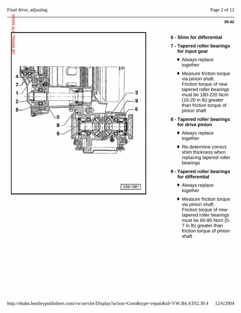
39-42
6 - Shim for differential
7 - Tapered roller bearings for input gear
Always replace together
Measure friction torque via pinion shaft. Friction torque of new tapered roller bearings must be 180-220 Ncm (16-20 in lb) greater than friction torque of pinion shaft
8 - Tapered roller bearings for drive pinion
Always replace together
Re-determine correct shim thickness when replacing tapered roller bearings
9 - Tapered roller bearings for differential
Always replace together
Measure friction torque via pinion shaft. Friction torque of new tapered roller bearings must be 60-80 Ncm (5-7 in lb) greater than friction torque of pinion shaft
Page 2 of 12Final drive, adjusting
12/6/2004http://ebahn.bentleypublishers.com/vw/servlet/Display?action=Goto&type=repair&id=VW.B4.AT02.39.4
WWW.ALL-TR
ANS.BY
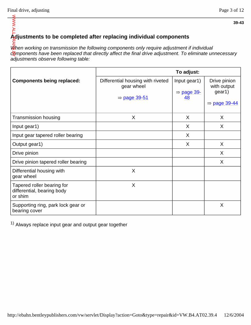
39-43
Adjustments to be completed after replacing individual components
When working on transmission the following components only require adjustment if individual components have been replaced that directly affect the final drive adjustment. To eliminate unnecessary adjustments observe following table:
To adjust:
Components being replaced: Differential housing with riveted gear wheel
page 39-51
Input gear1)
page 39-48
Drive pinion with output
gear1)
page 39-44
Transmission housing X X X
Input gear1) X X
Input gear tapered roller bearing X
Output gear1) X X
Drive pinion X
Drive pinion tapered roller bearing X
Differential housing with gear wheel
X
Tapered roller bearing for differential, bearing body or shim
X
Supporting ring, park lock gear or bearing cover
X
1) Always replace input gear and output gear together
Page 3 of 12Final drive, adjusting
12/6/2004http://ebahn.bentleypublishers.com/vw/servlet/Display?action=Goto&type=repair&id=VW.B4.AT02.39.4
WWW.ALL-TR
ANS.BY
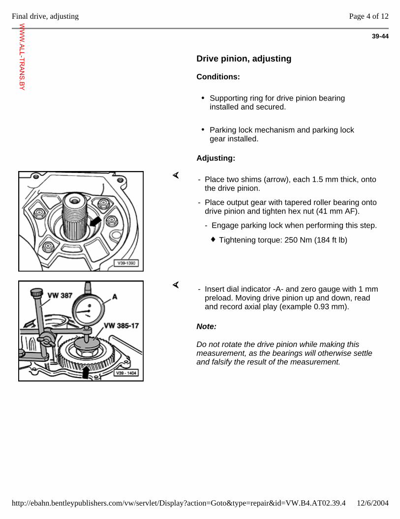
39-44
Drive pinion, adjusting
Conditions:
Supporting ring for drive pinion bearing installed and secured.
Parking lock mechanism and parking lock gear installed.
Adjusting:
- Place two shims (arrow), each 1.5 mm thick, onto the drive pinion.
- Place output gear with tapered roller bearing onto drive pinion and tighten hex nut (41 mm AF).
- Engage parking lock when performing this step.
Tightening torque: 250 Nm (184 ft lb)
Note:
Do not rotate the drive pinion while making this measurement, as the bearings will otherwise settle and falsify the result of the measurement.
- Insert dial indicator -A- and zero gauge with 1 mm preload. Moving drive pinion up and down, read and record axial play (example 0.93 mm).
Page 4 of 12Final drive, adjusting
12/6/2004http://ebahn.bentleypublishers.com/vw/servlet/Display?action=Goto&type=repair&id=VW.B4.AT02.39.4
WWW.ALL-TR
ANS.BY
39-45
Determining shim thickness
The specified bearing preload is achieved if the reading (example: 0.93 mm), the specified bearing preload (0.12 mm) and the amount allowed for compression (0.10mm) are deducted from the 2 x 1.5 mm thick shims.
Example:
Shims installed (2 x 1.5 mm) 3.00 mm
- Dial indicator reading - 0.93 mm
- Preload - 0.12 mm
- Amount for compression - 0.10 mm
= Thickness of shim 1.85 mm
- Remove output gear. Determine correct shim size from table, page 39-46 , and install shim on drive pinion.
- Re-install output gear, tighten hex nut, and secure with drift.
Tightening torque: 250 Nm (184 ft lb)
Page 5 of 12Final drive, adjusting
12/6/2004http://ebahn.bentleypublishers.com/vw/servlet/Display?action=Goto&type=repair&id=VW.B4.AT02.39.4
WWW.ALL-TR
ANS.BY
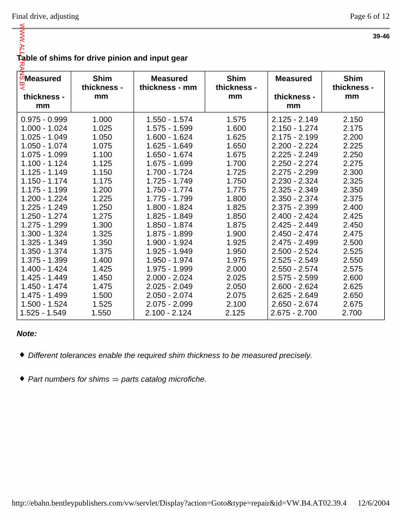
39-46
Table of shims for drive pinion and input gear
Measured
thickness - mm
Shim thickness -
mm
Measured thickness - mm
Shim thickness -
mm
Measured
thickness - mm
Shim thickness -
mm
0.975 - 0.999 1.000 - 1.024 1.025 - 1.049 1.050 - 1.074 1.075 - 1.099 1.100 - 1.124 1.125 - 1.149 1.150 - 1.174 1.175 - 1.199 1.200 - 1.224 1.225 - 1.249 1.250 - 1.274 1.275 - 1.299 1.300 - 1.324 1.325 - 1.349 1.350 - 1.374 1.375 - 1.399 1.400 - 1.424 1.425 - 1.449 1.450 - 1.474 1.475 - 1.499 1.500 - 1.524 1.525 - 1.549
1.000 1.025 1.050 1.075 1.100 1.125 1.150 1.175 1.200 1.225 1.250 1.275 1.300 1.325 1.350 1.375 1.400 1.425 1.450 1.475 1.500 1.525 1.550
1.550 - 1.574 1.575 - 1.599 1.600 - 1.624 1.625 - 1.649 1.650 - 1.674 1.675 - 1.699 1.700 - 1.724 1.725 - 1.749 1.750 - 1.774 1.775 - 1.799 1.800 - 1.824 1.825 - 1.849 1.850 - 1.874 1.875 - 1.899 1.900 - 1.924 1.925 - 1.949 1.950 - 1.974 1.975 - 1.999 2.000 - 2.024 2.025 - 2.049 2.050 - 2.074 2.075 - 2.099 2.100 - 2.124
1.575 1.600 1.625 1.650 1.675 1.700 1.725 1.750 1.775 1.800 1.825 1.850 1.875 1.900 1.925 1.950 1.975 2.000 2.025 2.050 2.075 2.100 2.125
2.125 - 2.149 2.150 - 1.274 2.175 - 2.199 2.200 - 2.224 2.225 - 2.249 2.250 - 2.274 2.275 - 2.299 2.230 - 2.324 2.325 - 2.349 2.350 - 2.374 2.375 - 2.399 2.400 - 2.424 2.425 - 2.449 2.450 - 2.474 2.475 - 2.499 2.500 - 2.524 2.525 - 2.549 2.550 - 2.574 2.575 - 2.599 2.600 - 2.624 2.625 - 2.649 2.650 - 2.674 2.675 - 2.700
2.150 2.175 2.200 2.225 2.250 2.275 2.300 2.325 2.350 2.375 2.400 2.425 2.450 2.475 2.500 2.525 2.550 2.575 2.600 2.625 2.650 2.675 2.700
Note:
Different tolerances enable the required shim thickness to be measured precisely.
Part numbers for shims parts catalog microfiche.
Page 6 of 12Final drive, adjusting
12/6/2004http://ebahn.bentleypublishers.com/vw/servlet/Display?action=Goto&type=repair&id=VW.B4.AT02.39.4
WWW.ALL-TR
ANS.BY
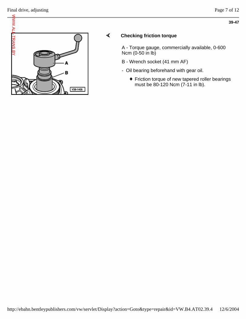
39-47
Checking friction torque
A - Torque gauge, commercially available, 0-600 Ncm (0-50 in lb)
B - Wrench socket (41 mm AF)
- Oil bearing beforehand with gear oil.
Friction torque of new tapered roller bearings must be 80-120 Ncm (7-11 in lb).
Page 7 of 12Final drive, adjusting
12/6/2004http://ebahn.bentleypublishers.com/vw/servlet/Display?action=Goto&type=repair&id=VW.B4.AT02.39.4
WWW.ALL-TR
ANS.BY
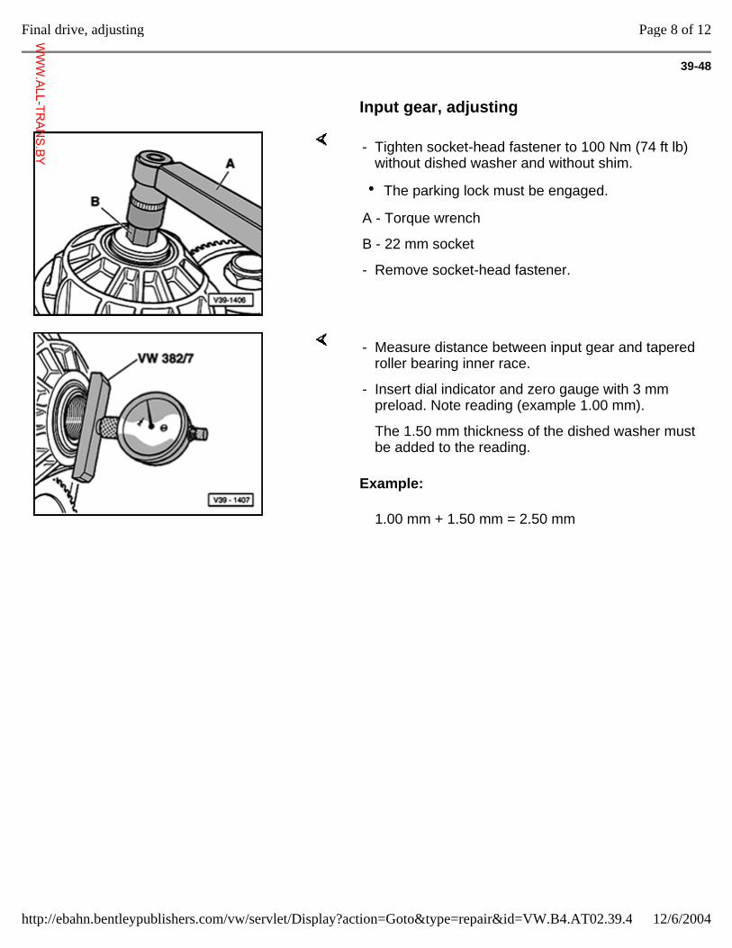
39-48
Input gear, adjusting
- Tighten socket-head fastener to 100 Nm (74 ft lb) without dished washer and without shim.
The parking lock must be engaged.
A - Torque wrench
B - 22 mm socket
- Remove socket-head fastener.
Example:
- Measure distance between input gear and tapered roller bearing inner race.
- Insert dial indicator and zero gauge with 3 mm preload. Note reading (example 1.00 mm).
The 1.50 mm thickness of the dished washer must be added to the reading.
1.00 mm + 1.50 mm = 2.50 mm
Page 8 of 12Final drive, adjusting
12/6/2004http://ebahn.bentleypublishers.com/vw/servlet/Display?action=Goto&type=repair&id=VW.B4.AT02.39.4
WWW.ALL-TR
ANS.BY
39-49
Determining shim thickness
The correct shim thickness determined by deducting the specified bearing preload of 0.18 mm from the figure of 2.50 mm (example) obtained from the measurement.
Example:
Dished washer thickness (1.50 mm) + dial indicator measurement (example: 1.00 mm)
2.50 mm
- Bearing preload - 0.18 mm
= Thickness of shim 2.32 mm
- Determine shim from table and fit onto drive shaft. Table of shims page 39-46 .
- Insert axial needle bearing and tighten socket-head fastener including dished washer.
Tightening torque: 250 Nm (184 ft lb)
Note:
Insert axial needle bearing for input shaft before tightening socket-head fastener. Installation position page 39-8 , Input gear, removing and installing.
Page 9 of 12Final drive, adjusting
12/6/2004http://ebahn.bentleypublishers.com/vw/servlet/Display?action=Goto&type=repair&id=VW.B4.AT02.39.4
WWW.ALL-TR
ANS.BY
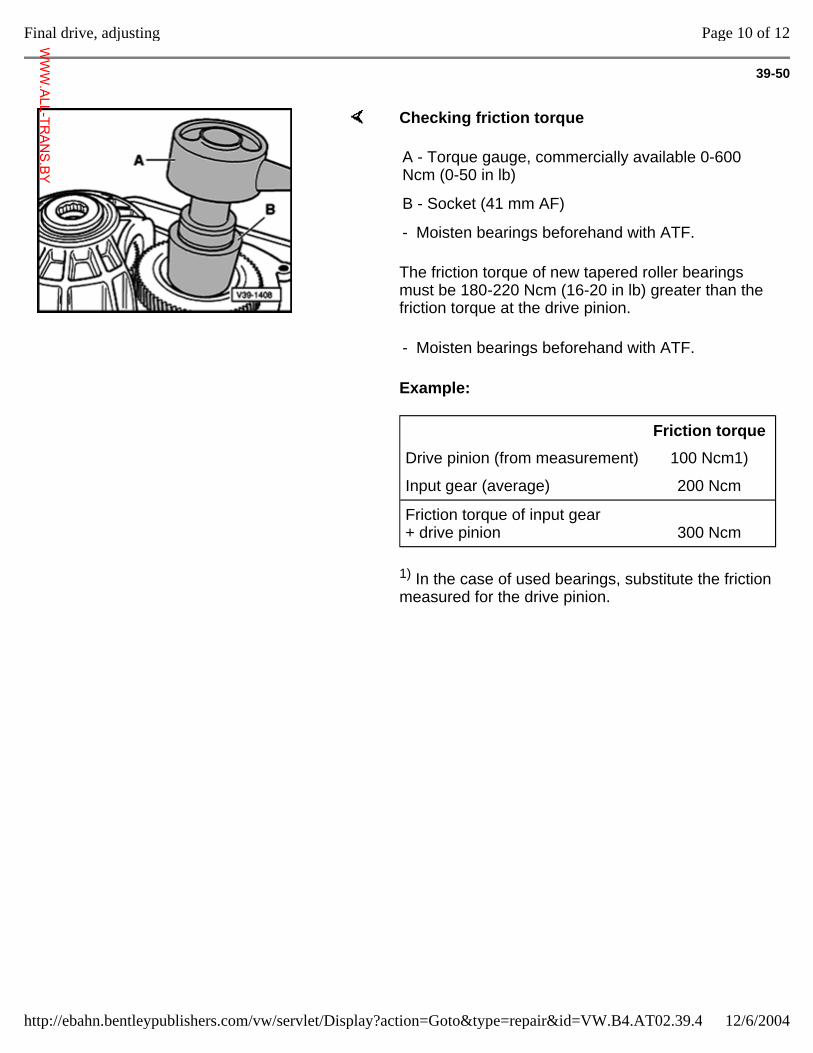
39-50
Checking friction torque
The friction torque of new tapered roller bearings must be 180-220 Ncm (16-20 in lb) greater than the friction torque at the drive pinion.
Example:
1) In the case of used bearings, substitute the friction measured for the drive pinion.
A - Torque gauge, commercially available 0-600 Ncm (0-50 in lb)
B - Socket (41 mm AF)
- Moisten bearings beforehand with ATF.
- Moisten bearings beforehand with ATF.
Friction torque
Drive pinion (from measurement) 100 Ncm1)
Input gear (average) 200 Ncm
Friction torque of input gear + drive pinion
300 Ncm
Page 10 of 12Final drive, adjusting
12/6/2004http://ebahn.bentleypublishers.com/vw/servlet/Display?action=Goto&type=repair&id=VW.B4.AT02.39.4
WWW.ALL-TR
ANS.BY
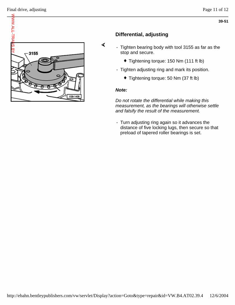
39-51
Differential, adjusting
Note:
Do not rotate the differential while making this measurement, as the bearings will otherwise settle and falsify the result of the measurement.
- Tighten bearing body with tool 3155 as far as the stop and secure.
Tightening torque: 150 Nm (111 ft lb)
- Tighten adjusting ring and mark its position.
Tightening torque: 50 Nm (37 ft lb)
- Turn adjusting ring again so it advances the distance of five locking lugs, then secure so that preload of tapered roller bearings is set.
Page 11 of 12Final drive, adjusting
12/6/2004http://ebahn.bentleypublishers.com/vw/servlet/Display?action=Goto&type=repair&id=VW.B4.AT02.39.4
WWW.ALL-TR
ANS.BY
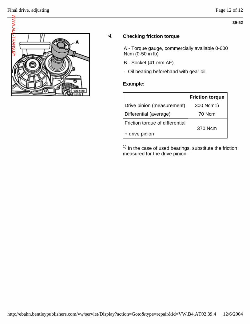
39-52
Checking friction torque
Example:
1) In the case of used bearings, substitute the friction measured for the drive pinion.
A - Torque gauge, commercially available 0-600 Ncm (0-50 in lb)
B - Socket (41 mm AF)
- Oil bearing beforehand with gear oil.
Friction torque
Drive pinion (measurement) 300 Ncm1)
Differential (average) 70 Ncm
Friction torque of differential + drive pinion
370 Ncm
Page 12 of 12Final drive, adjusting
12/6/2004http://ebahn.bentleypublishers.com/vw/servlet/Display?action=Goto&type=repair&id=VW.B4.AT02.39.4
WWW.ALL-TR
ANS.BY