40 SERIES GAS BURNER MODEL 400 NATURAL · PDF fileMODEL 400 NATURAL GAS/PROPANE INSTALLATION...
22
C6505020 STD G400 Manual Rev.5 -06/10/2002 1 40 SERIES GAS BURNER MODEL 400 NATURAL GAS/PROPANE INSTALLATION INSTRUCTIONS AND OWNER’S HANDBOOK CAUTION: All gas burners MUST be installed by trained and licensed technicians. WARNING: Installation of this burner must conform with local codes or, in the absence of local codes, with the Standard for the Installation of Domestic Gas Conversion Burners, ANSI Z21.8-1984, and Addendum, Z21.8a-1989, and the National Fuel Gas code, ANSI Z223.1-1984, and CAN/CGA B149.1 &.2. If an external electrical source is utilized, the conversion burner, when installed, must be electrically grounded in accordance with local codes or, in the absence of local codes, with the national Electrical Code, ANSI/NFPA No. 70-1990 and CSA Electrical Code. Owner is required to retain this manual for future reference. TECHNICAL SPECIFICATIONS FIRING RATE 170,000 TO 400,000 Btu/hr NATURAL PROPANE GAS SUPPLY PRESSURES MANIFOLD PRESSURES MIN. 4" w.c. MAX. 10" w.c. MIN. 0.90" w.c. MAX. 1.80" w.c. MIN. 8" w.c. MAX. 13" w.c. MIN. 1.04" w.c. MAX. 3.04" w.c. POWER 120 VOLTS 60 Hz 1 PHASE MOTOR 232T 2.2 AMPS 3250 RPM CONTROL MODULE 525 SE/A ELECTRONIC WARNING: If the information in these instructions is not followed exactly, a fire or explosion may result causing property damage, personal injury or death. Do not store or use gasoline or any other flammable vapours or liquid in the vicinity of this or any other appliance. WHAT TO DO IF YOU SMELL GAS: 1) Do not try to light any appliance. 2) Do not touch electrical switches; Do not use any phone in your building. 3) Immediately call your gas supplier from a neighbour's phone. Follow the gas supplier's instructions. 4) If you cannot reach your gas supplier, call the fire department. Installation and service must be performed by a qualified installer, service agency or the gas supplier.
-
Upload
nguyenkhuong -
Category
Documents
-
view
217 -
download
3
Transcript of 40 SERIES GAS BURNER MODEL 400 NATURAL · PDF fileMODEL 400 NATURAL GAS/PROPANE INSTALLATION...

C6505020 STD G400 Manual Rev.5 -06/10/2002 1
40 SERIES GAS BURNER MODEL 400 NATURAL GAS/PROPANE
INSTALLATION INSTRUCTIONS AND OWNER’S HANDBOOK CAUTION: All gas burners MUST be installed by trained and licensed technicians. WARNING: Installation of this burner must conform with local codes or, in the absence of local codes, with the Standard for the Installation of Domestic Gas Conversion Burners, ANSI Z21.8-1984, and Addendum, Z21.8a-1989, and the National Fuel Gas code, ANSI Z223.1-1984, and CAN/CGA B149.1 &.2. If an external electrical source is utilized, the conversion burner, when installed, must be electrically grounded in accordance with local codes or, in the absence of local codes, with the national Electrical Code, ANSI/NFPA No. 70-1990 and CSA Electrical Code. Owner is required to retain this manual for future reference.
TECHNICAL SPECIFICATIONS FIRING RATE 170,000 TO 400,000 Btu/hr
NATURAL PROPANE
GAS SUPPLY PRESSURES MANIFOLD PRESSURES
MIN. 4" w.c. MAX. 10" w.c.
MIN. 0.90" w.c. MAX. 1.80" w.c.
MIN. 8" w.c. MAX. 13" w.c.
MIN. 1.04" w.c. MAX. 3.04" w.c.
POWER 120 VOLTS 60 Hz 1 PHASE MOTOR 232T 2.2 AMPS 3250 RPM CONTROL MODULE 525 SE/A ELECTRONIC
WARNING: If the information in these instructions is not followed exactly, a fire or explosion may result causing property damage, personal injury or death.
Do not store or use gasoline or any other flammable vapours or liquid in the vicinity of this or any other appliance. WHAT TO DO IF YOU SMELL GAS: 1) Do not try to light any appliance. 2) Do not touch electrical switches; Do not use any phone in your building. 3) Immediately call your gas supplier from a neighbour's phone. Follow the gas supplier's instructions. 4) If you cannot reach your gas supplier, call the fire department. Installation and service must be performed by a qualified installer, service agency or the gas supplier.

C6505020 STD G400 Manual Rev.5 -06/10/2002 2
TABLE OF CONTENT
PRINCIPAL BURNER COMPONENTS ................................................................................................. 4
DIMENSIONS.......................................................................................................................................... 4
ELECTRODE & FLAME PROBE ADJUSTMENTS .............................................................................. 5
TYPICAL GAS TRAIN LAYOUT........................................................................................................... 6
INSTALLING THE BURNER ................................................................................................................. 7
INSTALLATION OF SEDIMENT TRAP & BURNER SUPPLY ........................................................... 9
FIELD WIRING DIAGRAM.................................................................................................................. 10
FACTORY WIRING DIAGRAM........................................................................................................... 10
SETTING UP THE BURNER ...........................................................................................................11-12
OPERATING FAULTS .......................................................................................................................... 12
AIR GATE ADJUSTMENT ................................................................................................................... 12
COMBUSTION HEAD SETTING ........................................................................................................ 13
MANIFOLD PRESSURES ................................................................................................................13-14
PRESSURE WORKING CHART........................................................................................................... 14
COMBUSTION CHECKS ..................................................................................................................... 15
STARTING CYCLE .............................................................................................................................. 16
PROBLEM SOLVING GUIDE .........................................................................................................16-17
OWNER INFORMATION & ROUTINE MAINTENANCE............................................................17-18
INSTALLATION DATA........................................................................................................................ 18
SPARE PARTS LIST.............................................................................................................................. 19
SPARE PARTS DIAGRAM .................................................................................................................. 20
Burner Start-up Form………………………………………………………………………………...21

C6505020 STD G400 Manual Rev.5 -06/10/2002 3
The following pages contain information, descriptions and diagrams for the proper installation and wiring of the burner. Please read carefully before attempting final installation.
The responsibility for ensuring that this manual is complete rests with the holder of these instructions.
SERIAL NUMBER IDENTIFICATION The Riello 15 character serial number, example, 99 A 8511111 00025, is identified as follows: 99 = last two digits of the year of manufacture; A = BI-week of manufacture; 8511111 = burner product code; 00025 = increment of 1 for each burner produced – specific to product code – reset to zero each January 1st.
(99) (A) (8511111) (00025)
Year of manufacture
BI-week of manufacture
Burner product code
Increment

C6505020 STD G400 Manual Rev.5 -06/10/2002 4
PRINCIPAL BURNER COMPONENTS 1. Air Damper (Optional Delete) 2. Air Gate Lock-screws 3. Wiring Terminal Block 4. Air Pressure Switch 5. Motor 6. Lockout Lamps and Reset Button 7. Cover Screw 8. Rubber Grommet 9. Capacitor
BURNER DIMENSIONS
Model 400 A B C F G *G1 H inches 10 5/16 12 1 3/8 13 11/16 3 3/4 10 4 1/8
mm 2262 305 35 347 95 255 61
*G1 is for LBT version Gasket thickness is 4 millimeters

C6505020 STD G400 Manual Rev.5 -06/10/2002 5
UNIVERSAL MOUNTING FLANGE
UNIVERSAL MOUNTING FLANGE DIMENSIONS A B C D inches 1 1/4 1/4 7/16 2 3/16 millimeters 32 6 11 56
ELECTRODE AND FLAME PROBE ADJUSTMENTS
IMPORTANT: Do not turn the ignition electrode. Leave it as shown in the drawing. If the ignition electrode is put near the ionization probe, the amplifier of the control box may be damaged.

C6505020 STD G400 Manual Rev.5 -06/10/2002 6
TYPICAL GAS TRAIN LAYOUT
1) GAS SUPPLY & FLOW DIRECTION OF GAS
2) GAS SUPPLY MAIN SHUTOFF MANUAL VALVE (FIELDSUPPLIED)
3) GAS SUPPLY PRESSURE TEST POINT (FIELD SUPPLIED)
4) GAS TRAIN PIPE DIAMETER SIZE(S):BURNER G120 1/2" NPT (REDUCED AT COMBUSTION HEADTO 3/8")BURNER(S) G200 & G400 3/4" NPT
GAS SUPPLY PRESSURE RANGES:
NATURAL GAS PRESSURE:MIN. = 4.0" WCMAX. 10.5" WC
L.P. PROPANE GAS PRESSURE:MIN. = 8.0" WCMAX. 13.0" WC
NOTE: ITEMS 5,6 & 7 COMBINATION GAS VALVE(S) ASSEMBLIES MAY BE UTILIZED WHERE APPROVED.
5) GAS APPLIANCE PRESSURE REGULATOR
6) SAFETY SHUTOFF GAS VALVE (VS) 24V OR 120VOPERATED
7) MAIN GAS VALVE (V1) 24V OR 120V OPERATEDSINGLE STAGE
8) GAS BURNER MANIFOLD TEST POINT
GAS TRAIN LEGEND
SEE GASSUPPLYRANGE
8
FIELD SUPPLIED
1 2 3 5 6
RIELLO SUPPLIED
74
Ø

C6505020 STD G400 Manual Rev.5 -06/10/2002 7
INSTALING THE BURNER Wet Base Illustration A) Burner Chassis B) Combustion Head Assembly 1. Locking Nut 2. Appliance Mounting Plate Insulation 3. Insulation Gasket Use this checklist prior to installation: 1) Check the input/output requirements
of the appliance. We suggest that the appliance output should be approximately 85% of input (85% efficiency).
2) Check the dimensions of the combustion chamber for correct sizing against the input requirements
of the application. 3) Check that there is sufficient air for proper combustion and adequate ventilation. Local codes
should be followed. In the absence of local codes, refer to the NFPA Manual No. 31, CAN/CGA B149.1 &.2, ANSI Z223.1-1984 and Addendum 221.8A 1989.
4) Check that you have adequate space for servicing the equipment. The Riello burner requires a
minimum of 13 inches clear space behind the red cover. This is required to allow easy removal of the cover for servicing and periodic maintenance.
5) Check that the chimney is of sufficient area to handle the exhaust gases. Make sure the chimney is
clear and there are no obstructions. 6) Barometric draft regulators must be of the double acting type, and must be installed in accordance
with the draft regulator manufacturer's instructions. Single acting barometric dampers are not permitted. For further clarification, refer to ANSI Z21.8-1984 and Z21.17A-1993.
NOTE: A vent shutoff system shall be applied to a barometric damper installed in the venting
system at the time of conversion of the appliance. This will electrically disconnect the burner should there be a blockage in the vent (chimney).
IMPORTANT: The installer must identify the main electrical power switch and manual gas shut off valve, for emergency conditions. The burner cover must be in place and secured before the burner is placed in operation. GENERAL INFORMATION Your Riello gas burner comes to you completely assembled and factory wired, ready for installation. Models equipped with the short combustion head have a fixed flange, which bolts directly to the front of the appliance. When equipped with the long combustion head, the burner comes with a universal flange, which when bolted to the appliance, allows the burner to be adjusted for exact positioning in the combustion zone.

C6505020 STD G400 Manual Rev.5 -06/10/2002 8
STEP-BY-STEP PROCEDURE
1) Remove the burner from the carton, taking care not to lose any of the supplied accessories. Check for signs of physical damage.
2) Bolt the combustion head and burner to the appliance. Be sure to install the supplied mounting gasket. Ensure that the burner is level (we suggest using a spirit level) and that the combustion head is centred in the appliance port. Refer to Page 7 for positioning of combustion head relative to the chamber.
3) Check that all gas train connections are tight and make your connections to the incoming gas supply.
a) A sediment trap must be provided. See pg. 9. b) If not already installed, a manual shutoff valve must be supplied. This valve must be upstream of
the burner gas train supply connection. c) A 1/8" NPT plugged tapping must be installed immediately upstream of the burner gas train supply connection and must be accessible for a test gauge.
d) If required by local codes, provide gas vent lines at the gas regulators and valve. e) Perform required gas pressure test on incoming gas supply lines.
NOTE: Details of sediment trap, manual gas valve, pressure test point, and line pressure test point can be found on Page 9.
4) To make electrical connections, refer to field wiring diagram on page 10. A manual disconnect switch must be installed in the incoming lines. Wiring to the low voltage-switching relay, if used, (Honeywell R8038A) must be rigid conduit or flexible approved cable.
CAUTION: Label all wires prior to disconnection when servicing controls. Wiring errors can cause improper and dangerous operation. Verify proper operation after servicing (Step 5 (e) below). CAUTION: The phase (HOT) wire must be connected to the black lead of the 24v relay if used; neutral to the white lead. Do not reverse the polarity. The burner will not operate with the Phase/Neutral reversed, and the control box may be damaged.
5) Check the burner functions as follows:
a) Make a final check on both the gas and electrical connections. b) Loosen the screw in the manifold gas test point and install an appropriate manometer. c) Set the thermostat at its highest setting. d) Switch on power. e) With the manual gas valve turned off, press the burner reset button (see page 4), and allow the burner to
run through a complete cycle to ensure that the sequence of operations is correct, (see page 16). A full starting cycle should take approximately 70 seconds from a no power condition until burner lockout, when equipped with motorized air damper, otherwise refer to the start-up cycle chart found on page 16.
f) Once the burner is operational (up and running) a final gas leak check must be completed on the gas train.
6) If the burner is installed on a central warm air furnace, affix the mandatory warning labe ls to the furnace fan cover door (inside and outside).

C6505020 STD G400 Manual Rev.5 -06/10/2002 9
INSTALLATION OF SEDIMENT TRAP AND BURNER SUPPLY Gas piping to the burner must be 1/2 inch minimum. Install only a full ported shutoff valve. The valve must be located outside the appliance jacket, and the pressure gauge port must be accessible. PRESSURE TEST-OVER 1/2 PSIG. The appliance and its individual shutoff valve must be disconnected from the gas supply piping system during any pressure testing of the system at a test pressure in excess of 1/2 PSIG. PRESSURE TEST-1/2 PSIG OR LESS The appliance must be isolated from the gas supply piping system by closing its individual manual shutoff valve during any testing of the gas supply piping system at test pressures equal to or less than 1/2 PSIG.

C6505020 STD G400 Manual Rev.5 -06/10/2002 10
FIELD WIRING DIAGRAM
FACTORY WIRING DIAGRAM
MM White
Brown
Blue
Black
Capacitor
NC NO
C
PA
525 SE/ACONTROL
BOX7
2
4125681
3
9
NLV2V1
Whi
te
Air damper motor
RIELLO POWER GAS BURNERMODELS G120, G200 & G400
INTERNAL FACTORY WIRING DIAGRAM:
A) Standard burner come with 120/24 volt transformer for 24voperated gas valves, for 120V operated gas valves deletetransformer.B) Optional AIR DAMPER MOTORC) Remote sensing of 525 SE/A control box lock out. Installersupplied and wired.
AB
Black
Black
Black
C
Optional wiring
Remote lock outsensing wiring
NOTE: 1) This burner is approved for use without the motorized air damper. In these instances optional wiring is used 2) The SAFETY SWITCH on the 525 SE CONTROL BOX is equipped with a contact allowing remote sensing of
burner lockout. The electrical connection is located on the CONTROL BOX terminal 4 as indicated. Should
24 Volt Relay *
V1 V2 L N L NGreen
Gnd.Gnd.
Green
24 Volts
120 Volts 60 Hz.
120 V controlled 24 V controlledOptional 24 V
controlled
operatingcontrol
serviceswitch
T T
N
F
L N
operatingcontrol
serviceswitch
F
L
whitered
black

C6505020 STD G400 Manual Rev.5 -06/10/2002 11
burner lockout occur, the 525 SE CONTROL BOX will supply a power source of 120 Vac to the connection terminal. The maximum allowable current draw on this terminal is 1 A.
IMPORTANT Terminal 4 is to be used only for the connection of a remote sensing device. If a neutral or ground lead is attached to terminal 4 the control box will be damaged should lockout occur
SETTING UP THE BURNER
After burner output has been determined, use TABLE 1 below AS AN INITIAL GUIDE for burner settings. Table 1
All settings in this table were obtained under the following conditions. ?? 0 (zero) draft in the combustion zone. ?? Small DIN test boiler. ?? 7” supply pressure for natural gas. ?? 11” supply pressure for
propane. ?? steady state (HOT) operating conditions
STEP BY STEP PROCEDURE
1) Set air gate. See AIR GATE ADJUSTMENT on pg. 13/14. 2) Set combustion head. See COMBUSTION HEAD SETTING on pg. 13. 3) Set the manifold pressure using the following method.
a) In order to determine existing manifold pressure, start the burner. At the end of the prepurge cycle (approx. 30s), the gas valve is energized. During the 5 sec. trial for ignition, note the manifold pressure. If the burner lights and continues to run, go to step (d).
b) Compare the observed manifold pressure from step (a) to the required value from TABLE 1. c) Repeat step (a), making adjustments to the gas valve, until flame is established. d) Once flame has been established, set your manifold pressure to the desired value from TABLE 1.
4) Check combustion gases using proper combustion analysis equipment to ensure safe levels of CO2 and CO during appliance heat up. The gas valve should be used to make any necessary adjustments to ensure safe combustion. At this point do not adjust the air or head settings unless absolutely necessary.
5) Allow burner to run until normal operating temperatures and condi tions have been achieved.
6) a) Clock the gas meter to determine actual burner output. b) Set the manifold pressure, by adjusting the gas valve, to achieve desired output. c) Check combustion gases once again to ensure safe operation. Make sure the burner cover is in
place and air gate locking screws are secure for all combustion analysis. Adjust air gate if necessary (refer to page12). This test must be done by a qualified technician. The maximum recommended CO2 level for natural gas is 10%; the maximum recommended level for propane gas is 12%. The recommended flue gas temperature is from 350?F to 550?F.
7) After completing the adjustments, remove the manometer and tighten the screw inside the manifold test point. Replace the regulator cap on the gas valve. 8) Complete the adjustment data tag, described on page18. Explain the burners essential functions (starting and stopping) to the owner. Do not forget to give the dealer or service company's name and address. Please see page17 and 18 for information on burner maintenance procedures. NOTE: Do not assume the heating system is operating at optimum performance.
Approximate Btu/hr Head Air gate Manifold burner output setting setting pressure
Natural Gas 170, 000 0.0 1.6 0.90”w.c. 216, 000 1.0 1.8 0.90”w.c. 262,000 2.0 2.2 1.00”w.c. 308,000 3.0 2.5 1.20”w.c. 354,000 4.0 2.8 1.42”w.c. 400,000 5.0 3.4 1.80 w.c. Propane 170, 000 0.0 1.6 1.04”w.c. 216, 000 1.0 1.8 1.16”w.c. 262,000 2.0 2.2 1.48”w.c. 308,000 3.0 2.5 1.80”w.c. 354,000 4.0 3.0 2.42”w.c. 400,000 5.0 3.6 3.04”w.c.
C6505020 STD G400 Manual Rev.5 -06/10/2002 12
THERE IS NO SUBSTITUTE FOR PROPER COMBUSTION TESTING
OPERATING FAULTS The integrated control system is self checking. The cycle from start up to flame establishment, takes approximately 70 seconds.
The burner will go into lockout under the following circumstances: a) Burner fails to ignite. b) The ionization probe is grounded. c) Opening of the air pressure switch or the normally open contacts of the air pressure switch not making.
Should overheating of the appliance occur, shut off the manual gas valve to the burner. Do NOT shut off the switch to the circulating pump or blower fan.
SHUT DOWN PROCEDURE
Switch off electrical power to the unit. Close the manual supply gas valve.
START UP PROCEDURE
See page 8, Item 5
NOTE: If an external electrical source is utilized, the conversion burner, when installed, must be electrically grounded in accordance with local codes. In the absence of local codes, refer to the National Electrical Code, ANSI/NFPA 70-1990.
In Canada follow the Canadian Electrical Code Part 1 CSA C22.1.
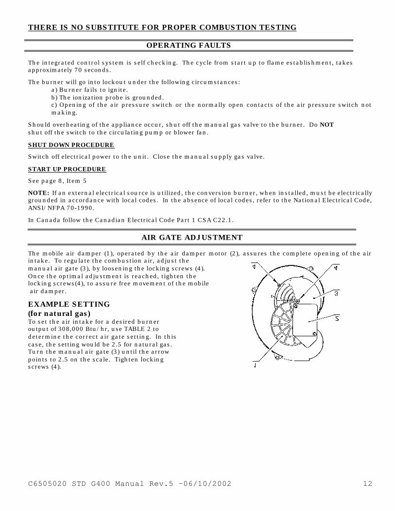
AIR GATE ADJUSTMENT
The mobile air damper (1), operated by the air damper motor (2), assures the complete opening of the air intake. To regulate the combustion air, adjust the manual air gate (3), by loosening the locking screws (4). Once the optimal adjustment is reached, tighten the locking screws(4), to assure free movement of the mobile air damper.
EXAMPLE SETTING (for natural gas) To set the air intake for a desired burner output of 308,000 Btu/hr, use TABLE 2 to determine the correct air gate setting. In this case, the setting would be 2.5 for natural gas. Turn the manual air gate (3) until the arrow points to 2.5 on the scale. Tighten locking screws (4).

C6505020 STD G400 Manual Rev.5 -06/10/2002 13
All settings in table 2 are obtained with zero (0) pressure in the combustion zone and at normal operating temperatures. i.e., steady state hot conditions. Please Note: Burner must be fired ONLY with fuel that is listed on the burner serial label.
COMBUSTION HEAD SETTING(Stop Gate) Loosen the Allen screw (A). Slide the elbow (B) so that the number on the indicator scale (D) aligns with the back edge of the air tube (C). See TABLE 3 for set points. Tighten the Allen screw (A). NOTE: To disassemble remove the combustion head, use the procedure below. 1) Remove the Allen screw completely. 2) Withdraw the head. 3) Pull the head straight out. Example (for natural gas): For a desired burner output of 308,000 Btu/hr, the combustion head setting would be 3.0 NOTE: This table is designed to ensure a good working pressure for the air proving switch. If a problem is encountered with the air switch proving combustion air flow, we suggest moving the head closer to the zero (0) set point. For a boiler or furnace with positive pressure in the combustion zone, we suggest moving the head closer to the zero (0) set point. All settings in table 3 are obtained with zero
(0) pressure in the combustion zone and at (1) normal
operating temperatures. i.e.; steady state hot conditions. Please Note: Burner must be fired ONLY with fuel that is listed on the burner serial label.
Table 2
Riello 40 Model 400 N/P Air Gate Settings
Burner Output Air Gate Setting Btu/hr x 1000 Natural Propane
170.0 1.6 1.6 216.0 1.8 1.8 262.0 2.2 2.2 308.0 2.5 2.5 354.0 2.8 3.0 400.0 3.4 3.6
Table 3 Riello 40 Model 400 N/P
Combustion Head Settings (STOP GATE) Burner Output Head Setting Btu/hr x 1000 Natural Propane
170.0 0.0 0.0 216.0 1.0 1.0 262.0 2.0 2.0 308.0 3.0 3.0 354.0 4.0 4.0 400.0 5.0 5.0

C6505020 STD G400 Manual Rev.5 -06/10/2002 14
MANIFOLD PRESSURES Manifold gas pressure for various firing rates must be set by adjusting the gas regulator of the gas valve. To check manifold gas pressure, attach a manometer to the manifold test point, shown on typical gas train layout on page 6. Approximate manifold pressure settings are indicated in TABLE 4. Example (for natural gas): For a burner to be fired at 308,000 Btu/hr, the manifold pressure would be approximately 1.20" w.c. (inches of water column).
Manifold pressure will have to be adjusted to compensate for varying application conditions. All settings in table 4 are obtained with zero (0) pressure in the combustion zone and at normal operating temperatures. i.e.; steady state hot conditions. Please Note: Burner must be fired ONLY with fuel that is listed on the burner serial label.
HIGH ALTITUDE SETTINGS It should be noted that for higher altitudes more air for combustion is required. All settings in this manual have been obtained at approximately sea level. Special attention should be paid to air for combustion at elevations above sea level. If an increase in combustion air is insufficient, the burner must then be derated by approximately 4% for every 1000 feet above sea level.
PRESSURE WORKING CHART The chart below shows effects of pressure in the combustion zone on the minimum/maximum burner outputs. In this example, with a maximum operating pressure of 0.6 inches water column in the combustion zone, you will be able to obtain a maximum of 370,000 Btu/hr burner output.
Table 4 Riello 40 Model 400 N/P Manifold Pressure Inches of w.c. Burner Output Inches of w.c.
Btu/hr x 1000 Natural Propane 170.0 0.90 1.04 216.0 0.90 1.16 262.0 1.00 1.48 308.0 1.20 1.80 354.0 1.42 2.42 400.0 1.80 3.04
0.0
0.5
1.0
1.5
2.0
2.5
3.0
3.5
170 210 250 290 330 370 410
PRESSURE WORKING CHARTNatural and LPG gas
INPUT (000's) BTUH
PR
ES
SU
RE
In/wc

C6505020 STD G400 Manual Rev.5 -06/10/2002 15
Any change from zero (0) pressure in the combustion zone will affect the Btu output of the burner. To supply the required input to the appliance, manifold pressure will have to be adjusted to compensate for this condition.
NOTES: 1) Sizes shown above are for cylindrical or wet base boilers, or air cooled heat exchangers. 2) To size the chamber in applications other than wet base boilers, you must calculate area in square inches
of the combustion zone required to give you a grate area or floor area to match the BTU inputs according to the local authority. Refer to CAN/CGA B149.1 & .2 ANSI Z21.8-1984, and ANSI Z223.1-1984.
3) Fire brick or cerafelt chamber materials should have a continuous run temperature rating of 2400 degrees Fahrenheit and a melting point of 3000 degrees Fahrenheit.
COMBUSTION CHECKS CO2 It is advisable not to exceed a measured reading of 10% CO2 for Natural Gas or 12% CO2 for Propane Gas. CO For safety reasons, the value of .02% (200ppm) free air sample must not be exceeded. IONIZATION CURRENT The minimum amount of current necessary for the control box to operate properly is 5 microamps DC. To measure the ionization current, disconnect the red wire connector and insert a DC micro ampmeter in series with control box terminal 2 and the ionization probe which senses the flame. Refer to the diagram below.
14
16
18
20
22
24
26
28
150 200 250 300 350 400
COMBUSTION CHAMBER SIZERecommended Minimum Sizes
INPUT (000's) BTUH
Inches
12
10
LENG
TH
DIAMETER

C6505020 STD G400 Manual Rev.5 -06/10/2002 16
Burner Start-up Cycle
Ionization Current Check
PROBLEM SOLVING GUIDE Burner starting difficulties and their causes: 1) The burner goes through the prepurge period normally. The flame ignites, but the burner goes to lockout
within five seconds. a) The phase/neutral lines are reversed. b) The wiring to ground is absent or ineffective. c) The ionization probe is grounded, or not in contact with the flame, or the circuit to the control box is
broken. d) The spark interferes with the flame signal due to incorrect setting of the electrode.
2) The burner goes to lockout after the prepurge period because the flame does not ignite.
a) Air has not been fully bled from the gas lines. b) The gas valve is passing too little gas. c) The spark is irregular or not present.
C6505020 STD G400 Manual Rev.5 -06/10/2002 17
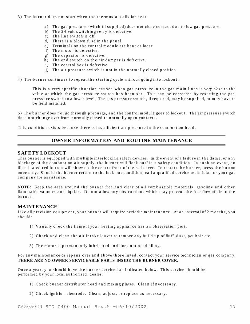
3) The burner does not start when the thermostat calls for heat.
4) The burner continues to repeat the starting cycle without going into lockout.
This is a very specific situation caused when gas pressure in the gas main lines is very close to the value at which the gas pressure switch has been set. This can be corrected by resetting the gas pressure switch to a lower level. The gas pressure switch, if required, may be supplied, or may have to be field installed.
5) The burner does not go through prepurge, and the control module goes to lockout. The air pressure switch does not change over from normally closed to normally open contacts. This condition exists because there is insufficient air pressure in the combustion head.
OWNER INFORMATION AND ROUTINE MAINTENANCE SAFETY LOCKOUT This burner is equipped with multiple interlocking safety devices. In the event of a failure in the flame, or any blockage of the combustion air supply, the burner will "lock out" in a safety condition. In such an event, an illuminated red button will show on the centre front of the red cover. To restart the burner, press the button once only. Should the burner return to the lock out condition, call a qualified service technician or your gas company for assistance. NOTE: Keep the area around the burner free and clear of all combustible materials, gasoline and other flammable vapours and liquids. Do not allow any obstructions which may prevent the free flow of air to the burner. MAINTENANCE Like all precision equipment, your burner will require periodic maintenance. At an interval of 2 months, you should:
1) Visually check the flame if your heating appliance has an observation port. 2) Check and clean the air intake louver to remove any build up of fluff, dust, pet hair etc. 3) The motor is permanently lubricated and does not need oiling.
For any maintenance or repairs over and above those listed, contact your service technician or gas company. THERE ARE NO OWNER SERVICEABLE PARTS INSIDE THE BURNER COVER. Once a year, you should have the burner serviced as indicated below. This service should be performed by your local authorized dealer.
1) Check burner distributor head and mixing plates. Clean if necessary. 2) Check ignition electrode. Clean, adjust, or replace as necessary.
a) The gas pressure switch (if supplied) does not close contact due to low gas pressure. b) The 24 volt switching relay is defective. c) The line switch is off. d) There is a blown fuse in the panel. e) Terminals on the control module are bent or loose f) The motor is defective. g) The capacitor is defective. h) The end switch on the air damper is defective. i) The control box is defective. j) The air pressure switch is not in the normally closed position

C6505020 STD G400 Manual Rev.5 -06/10/2002 18
3) Check the flame sensor rod (ionization rod) for dirt or carbon build up. Clean, adjust, or replace as necessary.
4) Check manifold gas pressure. 5) Check all burner adjustments. 6) Generally clean all exposed parts and components. 7) Do a complete combustion test with the burner cover in place and the air gate locking screws secure.
Your Riello 40 gas burner is only part of your heating system. Once every year you should have your heating appliance serviced by a qualified service technician. You should also have the chimney checked, and cleaned if necessary.
INSTALLATION DATA
Note: This label is supplied in the package with the burner and should be filled out and affixed to the appliance when the conversion burner is installed.

C6505020 STD G400 Manual Rev.5 -06/10/2002 19
SPARE PARTS
GAS BURNER SYSTEM RIELLO 40 N400
REVISED: 10/01
No.
SPARE PARTS CODE
DESCRIPTION
No.
SPARE PARTS CODE
DESCRIPTION
1 3007238 Burner back cover 21 3950371 Short combustion head (279T1)
2 C7020008 Air switch 22 3006696 Drawer assembly elbow
3 3001162 Primary control box 525 SE/A 23 3007275 Electrode assembly
4 3002307 Primary control sub-base 24 3007265 Electrode and ionization clamp
5 C7020006 120/24 volt transformer 25 3006708 Ionization assembly
6 3007288 Air switch tube and connector 26 3006702 Natural gas orifice
7 3007310 Ionization lead 27 3006699 Distributor head and mixing plate
8 3007293 Air tube cover plate 28 3007299 Manifold
9 3006688 Chassis mounting collar 29 3006693 End cone
10 3007223 Chassis front plate 30 3005447 Gas test point
11 3007279 Air damper motor 31 3000870 Hinge assembly
12 3006930 Motorized air damper
13 3007205 Manual air shutter(air gate) 33 3950372 Long combustion head (279T2)
14 3007209 Air intake housing 34 3006696 Drawer assembly elbow
15 3005788 Fan 35 3007276 Electrode assembly
16 3005834 Capacitor 10?F 36 3007265 Electrode & ionization clamp
17 3005843 Burner motor 37 3007277 Ionization assembly
18 3005856 Mounting gasket 38 3007300 Manifold
19 3006356 Universal mounting flange 39 3007290 Natural gas tube
20 3007448 Ground lead and connector 40 3005854 Semi flange 2 required
41 3006693 End cone
42 3007282 End cone adapter
49 C7010003 Mounting bracket-Transformer 43 3006702 Natural gas orifice
44 3006699 Distributor head and mixing plate
ACCESSORIES 45 3007303 Electrode support
C7020004 Honeywell R8038A 24 v switching relay
46 3007285 Air tube -long
47 3005447 Gas test point
48 3000870 Hinge assembly

C6505020 STD G400 Manual Rev.5 -06/10/2002 20

C6505020 STD G400 Manual Rev.5 -06/10/2002 21
35 Pond Park Rd. Hingham, MA 02043 Phone: 781-749-8292
Toll Free: 800-992-7637 Fax: 781-740-2069
2165 Meadowpine Blvd. Mississauga,On L5H 3R2
Phone: 905-542-0303 Toll Free: 800-387-3898
Fax: 905-542-1525
BURNER START- UP FORM *
Burner S/N. or Model: Appliance:
Installer name:
Company: Installation date:
Address:
Phone: Fax:
Owner Name:
Address:
Phone: E-mail:
Burner Start-up Info (OIL) Burner Start-up Info (GAS)
Nozzle Info: Gas Supply Pressure:
Pump Pressure: Pump pressure:
Air Setting: Turbulator setting: Air Setting: Head Setting:
Draft Overfire: Draft
breech: Draft Overfire: Draft breech:
CO2: CO: O2:
CO2: CO: O2:
Smoke density: (Bacharach) Manifold pressure: Single Line:
Two Lines:
Ionization Reading µAdc: Input BTU/Hr:
* This form was designed and provided in the installation manual for reference and also for providing technical information which can be faxed or mailed to our technical hot-line coordinator when technical assistance is required. Please complete this form, fax it or mail it at the address/fax above, or send an e-mail with the information listed below to: [email protected]

C6505020 STD G400 Manual Rev.5 -06/10/2002 22
35 Pond Park Road Hingham, MA 02043 Phone 781-749-8292
Toll Free 800-992-7637 Fax 781-740-2069
www.riellousa.com
2165 Meadowpine Blvd Mississauga, ON L5N 6H6 Phone 905-542-0303 Toll Free 800-387-3898 Fax 905-542-1525 www.riellocanada.com
Technical Support Hotline 1-800-4-RIELLO
1-800-474-3556