3GPP NR V2X Mode 2: Overview, Models and System-Level ...
26
Received May 31, 2021, accepted June 16, 2021, date of publication June 21, 2021, date of current version June 29, 2021. Digital Object Identifier 10.1109/ACCESS.2021.3090855 3GPP NR V2X Mode 2: Overview, Models and System-Level Evaluation ZORAZE ALI 1 , SANDRA LAGÉN 1 , (Senior Member, IEEE), LORENZA GIUPPONI 1 , AND RICHARD ROUIL 2 1 Centre Tecnològic de Telecomunicacions de Catalunya (CTTC/CERCA), 08860 Castelldefels, Spain 2 National Institute of Standards and Technology (NIST), Gaithersburg, MD 20899, USA Corresponding author: Zoraze Ali ([email protected]) This work was supported in part by the Spanish Ministry of Economy and Competitiveness (MINECO) through 5G REsource EfFIcient 5G NEtwork (5G-REFINE) under Grant TEC2017-88373-R, in part by the Generalitat de Catalunya under Grant 2017 SGR 1195, and in part by the National Institute of Standards and Technology (NIST) from the USA Department of Commerce under Award 60NANB20d001. ABSTRACT Following the successful use of sidelink in Long Term Evolution (LTE) for Proximity Services (ProSe) and Cellular Vehicular-to-everything (C-V2X), the 3rd Generation Partnership Project (3GPP) is working towards its evolution in New Radio (NR) systems in the context of the so-called NR V2X. This new technology is expected to complement LTE C-V2X for advanced services by offering low latency, high reliability, and high throughput V2X services for advanced driving use cases. To do this, NR V2X is equipped with new features, such as the support for groupcast and unicast communication, a novel feedback channel, and a new control channel design. In this paper, we provide a complete history of sidelink technology in 3GPP followed by a detailed overview of NR V2X technology, with special emphasis on Mode 2 for out of coverage operation and autonomous resource selection. Furthermore, this paper presents a system-level NR V2X standard-compliant simulator, as an extension of the popular and open-source NR network simulator 5G-LENA, based on ns-3. In particular, we focus on the design, implementation, and evaluation of the sensing-based resource selection in NR V2X Mode 2, in a highway scenario. Through several and extensive simulation campaigns, we test the impact of different NR V2X parameters, such as the numerology, the resource selection window size, the number of retransmissions, the maximum number of resources per reservation, and the probability of keeping the same resources during reselection, in a sensing-based resource selection. Finally, we provide a comparison campaign that shows the gains attained by the sensing-based resource selection, proposed during 3GPP Release 16, over the random selection strategy, considered in 3GPP Release 17 for power saving purposes. INDEX TERMS Vehicular communications, 3GPP, NR V2X, autonomous resource selection, network simulations. ACRONYMS P rsvp Resource Reservation Period 3GPP 3rd Generation Partnership Project 5G Fifth-Generation 5GAA 5G Automotive Association BSR Buffer Status Report BWP Bandwidth Part C-V2X Cellular V2X CDF Cumulative Distribution Function CP Cyclic Prefix CSI Channel State Information D2D Device-to-Device The associate editor coordinating the review of this manuscript and approving it for publication was Fakhrul Alam . DMRS Demodulation Reference Signals DSRC Dedicated Short Range Communications eNB Evolved Node B EPS Evolved Packet System gNB next-Generation Node B HARQ Hybrid Automatic Repeat Request IE Information Element IP Internet Protocol ITS Intelligent Transport System KPI Key Performance Indicator LC Logical Channel LCID Logical Channel Identifier LTE Long Term Evolution MAC Medium Access Control MCS Modulation Coding Scheme 89554 This work is licensed under a Creative Commons Attribution 4.0 License. For more information, see https://creativecommons.org/licenses/by/4.0/ VOLUME 9, 2021
Transcript of 3GPP NR V2X Mode 2: Overview, Models and System-Level ...
Received May 31, 2021, accepted June 16, 2021, date of publication June 21, 2021, date of current version June 29, 2021.
Digital Object Identifier 10.1109/ACCESS.2021.3090855
3GPP NR V2X Mode 2: Overview, Modelsand System-Level EvaluationZORAZE ALI 1, SANDRA LAGÉN 1, (Senior Member, IEEE),LORENZA GIUPPONI 1, AND RICHARD ROUIL 21Centre Tecnològic de Telecomunicacions de Catalunya (CTTC/CERCA), 08860 Castelldefels, Spain2National Institute of Standards and Technology (NIST), Gaithersburg, MD 20899, USA
Corresponding author: Zoraze Ali ([email protected])
This work was supported in part by the Spanish Ministry of Economy and Competitiveness (MINECO) through 5G REsource EfFIcient 5GNEtwork (5G-REFINE) under Grant TEC2017-88373-R, in part by the Generalitat de Catalunya under Grant 2017 SGR 1195, and in partby the National Institute of Standards and Technology (NIST) from the USA Department of Commerce under Award 60NANB20d001.
ABSTRACT Following the successful use of sidelink in Long Term Evolution (LTE) for ProximityServices (ProSe) and Cellular Vehicular-to-everything (C-V2X), the 3rd Generation Partnership Project(3GPP) is working towards its evolution in New Radio (NR) systems in the context of the so-called NRV2X. This new technology is expected to complement LTE C-V2X for advanced services by offering lowlatency, high reliability, and high throughput V2X services for advanced driving use cases. To do this,NR V2X is equipped with new features, such as the support for groupcast and unicast communication,a novel feedback channel, and a new control channel design. In this paper, we provide a complete history ofsidelink technology in 3GPP followed by a detailed overview of NR V2X technology, with special emphasisonMode 2 for out of coverage operation and autonomous resource selection. Furthermore, this paper presentsa system-level NR V2X standard-compliant simulator, as an extension of the popular and open-source NRnetwork simulator 5G-LENA, based on ns-3. In particular, we focus on the design, implementation, andevaluation of the sensing-based resource selection in NR V2X Mode 2, in a highway scenario. Throughseveral and extensive simulation campaigns, we test the impact of different NR V2X parameters, such asthe numerology, the resource selection window size, the number of retransmissions, the maximum numberof resources per reservation, and the probability of keeping the same resources during reselection, in asensing-based resource selection. Finally, we provide a comparison campaign that shows the gains attainedby the sensing-based resource selection, proposed during 3GPP Release 16, over the random selectionstrategy, considered in 3GPP Release 17 for power saving purposes.
INDEX TERMS Vehicular communications, 3GPP, NR V2X, autonomous resource selection, networksimulations.
ACRONYMSPrsvp Resource Reservation Period3GPP 3rd Generation Partnership Project5G Fifth-Generation5GAA 5G Automotive AssociationBSR Buffer Status ReportBWP Bandwidth PartC-V2X Cellular V2XCDF Cumulative Distribution FunctionCP Cyclic PrefixCSI Channel State InformationD2D Device-to-Device
The associate editor coordinating the review of this manuscript and
approving it for publication was Fakhrul Alam .
DMRS Demodulation Reference SignalsDSRC Dedicated Short Range CommunicationseNB Evolved Node BEPS Evolved Packet SystemgNB next-Generation Node BHARQ Hybrid Automatic Repeat RequestIE Information ElementIP Internet ProtocolITS Intelligent Transport SystemKPI Key Performance IndicatorLC Logical ChannelLCID Logical Channel IdentifierLTE Long Term EvolutionMAC Medium Access ControlMCS Modulation Coding Scheme
89554 This work is licensed under a Creative Commons Attribution 4.0 License. For more information, see https://creativecommons.org/licenses/by/4.0/ VOLUME 9, 2021
Z. Ali et al.: 3GPP NR V2X Mode 2: Overview, Models and System-Level Evaluation
MIMO Multiple-Input Multiple-OutputmmWave millimeter-waveNAS Non-Access StratumNDI New Data IndicatorNR New RadioOFDM Orthogonal Frequency Division MultiplexingPDCP Packet Data Convergence ProtocolPDU Packet Data UnitPHY PhysicalPIR Packet Inter-reception DelayPRR Packet Reception RatioPSBCH Physical Sidelink Broadcast ChannelPSCCH Physical Sidelink Control ChannelPSFCH Physical Sidelink Feedback ChannelPSSCH Physical Sidelink Shared ChannelRB Resource BlockRE Resource ElementRLC Radio Link ControlRRC Radio Resource ControlRSRP Reference Signal Received PowerRV Redundancy VersionSCI Sidelink Control InformationSCS sub-carrier spacingSI Study ItemSLRRC Sidelink Resource Reselection CounterSPS Semi-Persistent SchedulingSUMO Simulation of Urban MObilityTBS Transport Block SizeTDD Time Division DuplexTDMA Time-Division Multiple AccessTFT Traffic Flow TemplateTR Technical ReportTS Technical SpecificationTTI Transmission Time IntervalUE User EquipmentUM Unacknowledged ModeV2I Vehicle-to-InfrastructureV2N Vehicle-to-NetworkV2P Vehicle-to-PedestrianV2V Vehicle-to-VehicleV2X Vehicular-to-everythingWI Work Item
I. INTRODUCTIONThe automotive industry is currently transitioning towardsautomated driving and advanced driver assisted systems,where vehicles are able to react by themselves to changesin the driving environment. In this context, Vehicular-to-everything (V2X) is seen as a key technology to providecomplete environmental awareness around the vehicle byexchanging messages with other vehicles, roadside units, andpedestrians with low latency and high reliability. V2X com-munications are expected to provide potentiality in differentareas, like faster alerts and notifications, law enforcement,better service on roadways, reduced world-wide traffic load,
reduced emissions, time savings, and increased automotivesafety, thus contributing to prevent crashes/injuries and savelives [1]. Additionally, V2X-capable vehicles can assist inbetter traffic management also for non-safety applications.Several advanced V2X use cases have been already proposedwithin the Third Generation Partnership Project (3GPP)Release 15 such as vehicle platooning, extended sensors,advanced and remote driving, or cooperative collision avoid-ance [2]. Also, industrial associations like the 5GAutomotiveAssociation (5GAA) in Europe have been built to promote thevision of connected mobility, including autonomous drivingand intelligent transportation [3].
As of today, the two key radio access technologies thatenable vehicular communications are 1) Dedicated ShortRange Communications (DSRC), standardized by IEEEin 802.11p [4] and the more recent 802.11bd [5], and2) Long Term Evolution (LTE) Cellular V2X (C-V2X), basedon 3GPP LTE Release 14 and Release 15 [6]. DSRC isdesigned to primarily operate in the 5.9 GHz band, whileC-V2X is thought to operate in both 5.9 GHz and in cellularlicensed carriers at sub 6 GHz carrier frequencies. Differ-ently from DSRC that focused on Vehicle-to-Vehicle (V2V)and Vehicle-to-Infrastructure (V2I) communications, C-V2Xencompasses V2V, Vehicle-to-Pedestrian (V2P), V2I andVehicle-to-Network (V2N) [7]. C-V2X is designed to sup-port basic safety message sharing among proximity users,such as collision warning, emergency stop warning, andadaptive cruise control. A comparison study in [8] showsthat LTE C-V2X gets a superior reliability performanceover DSRC, due to the more efficient Physical (PHY) layerof LTE C-V2X.
V2X requirements can be met using LTE C-V2X, as longas the vehicular density is not too high [6]. However, as thequality of service requirements becomemore stringent, whichis the case in many V2X applications, LTE C-V2X fallsshort, and Fifth-Generation (5G) New Radio (NR) is calledas a complementary solution [5]. Towards that goal, 3GPPRelease 16 has included a Study Item (SI) to support newapplications with more stringent requirements, which hasresulted in Technical Report (TR) 38.885 [9]. Based on thestudy outcome captured in this TR, 3GPP Release 16 hascompleted a Work Item (WI) in July 2020 to standardizeV2X on top of 5G NR standardized in Release 15 [10].As a main design principle, NR is not designed to bebackward compatible with LTE. Similarly, NR V2X is notbackward compatible with LTE C-V2X. The NR V2X SIindicates that the design objective of NR V2X is not toreplace LTE C-V2X, but to supplement C-V2X in supportingthose use cases that cannot be supported by LTE C-V2X [9].To ensure that NR V2X can provide a unified support for allV2X applications in the future, NR V2X must be capable ofsupporting not only advancedV2X applications but also basicsafety applications that are supported today by LTE C-V2X.
Such a wide applications and use cases’ support is possiblein NR V2X because of the flexible framework inheritedby the NR technology and the recent progresses envisioned
VOLUME 9, 2021 89555
Z. Ali et al.: 3GPP NR V2X Mode 2: Overview, Models and System-Level Evaluation
in NR V2X standardization, which includes many enhance-ments over LTE C-V2X concepts. The NR radio accesstechnology provides wide bandwidth support in various fre-quency ranges (including sub 6 GHz bands and millimeter-wave (mmWave) bands), flexible frame structure withreduced transmission time intervals (by means of multiplenumerologies and sub-carrier spacing (SCS) support), sup-port for massive Multiple-Input Multiple-Output (MIMO)systems and high modulation orders, and advanced channelcoding [11]. All these new features and functionalities intrin-sically contribute to increase the data rate, reduce the latency,and improve the spectral efficiency of V2X communicationsystems. In addition, new enhancements and key procedureshave been defined for NR V2X, specifically designed toimprove the reliability of V2X communications systems,such as new communication types (unicast and groupcast),a new feedback channel, the support of feedback-basedretransmissions, and new resource allocation and schedulingmechanisms [9].
While LTE C-V2X has been widely studied analyticallyand through simulations by academia and industry [6], [8],[12]–[14], the studies on NR V2X have just started. Authorsin [15] provide an overview of the standardization activitiesfor vehicular communications at mmWave bands, includingIEEE 802.11bd and 3GPP NR V2X specifications. Authorsin [16] review the NR V2X design in 3GPP Release 16,with respect to the network architecture, security, andprotocol enhancements. Authors in [17] provide a com-prehensive overview of 3GPP NR sidelink transmissions,including physical layer structure, resource allocation mech-anisms, and synchronization procedures. A more in-depthtutorial of 3GPP Release 16 NR V2X standard is presentedin [18], including overview of the PHY layer, resource allo-cation, quality of service management, mobility manage-ment for V2N communications, and coexistence mechanismsbetween NR V2X and LTE C-V2X. In [19], the impact of theNR numerology on the V2X autonomous sidelink mode(similar to NR V2X Mode 2) is assessed. However, in [19],the evaluation is done over an LTE C-V2X simulator.
As it can be observed from the above review, most of thepublicly available papers about NR V2X deal with a 3GPPstandard overview, but few of these works discuss simulationstudies and to the best of the authors’ knowledge none ofthem is based on Release 16 NR-compliant V2X simulationmodels, because the standardization has recently been com-pleted. In addition, a key challenge to evaluate performanceof NR V2X is that, despite the set of simulation results byindustry and in literature, the simulators are not publiclyavailable. Normally, simulators used in 3GPP are requiredto pass through a calibration procedure, but they are private,and not available to the research community. Consequently,the obtained results are nor reproducible, neither comparable,and system performance metrics are presented without muchdetails revealed about the underlying models and assump-tions. There are then private commercial simulators that areavailable after paying an annual license fee for using them.
Often, if not in all cases, the license is very restrictive anddoes not allowmodifications or inspection of the source code,which is a clear limitation for the research and the poten-tial innovation. To the best of our knowledge, open sourceend-to-end simulators for 5G V2X communications com-pliant with NR V2X Release 16 specifications are not yetavailable to the research community.
There are five main open source and end-to-end simulatorsthat have been developed to simulate sidelink communica-tions. First, an LTE Device-to-Device (D2D) communica-tion simulation model based on ns-3 was introduced andvalidated in [20]. Models are currently available throughthe ns-3 App store. Authors in [21] presented the firstopen-source simulator for LTE C-V2X Mode 4 communi-cations, based on ns-3. An open-source 802.11p and LTEC-V2X simulation/emulation tool for ns-3, called ms-van3t,has been recently released in [22], which provides integrationof ns-3 with the open-source Simulation of Urban MObility(SUMO) simulator for mobility management and mobilitytracking. The work in [23] presents LTEV2Vsim, a simu-lator for LTE C-V2X Mode 3 and Mode 4 that is writtenin Matlab, freely available, and which focuses on MediumAccess Control (MAC) and PHY layers procedures. Finally,authors in [24] introduced an ns-3 simulator for NR V2X atmmWave carrier frequencies. The model in [24] is compliantwith 3GPP antenna and channel modeling for NR V2X, butnot with NR V2X specifications at Radio Resource Con-trol (RRC) and MAC layers. In particular, the model wasdeveloped before the finalization of NR V2X specifications.Therefore, at MAC layer it follows Mode 2 (c) for resourceallocation, whichwas proposed as one of the options for studyin 3GPP TR 38.885 [9]. Specifically, it uses Time DivisionMultiple Access (TDMA) to assign resources using the slotsin a subframe, i.e., User Equipments (UEs) scheduled in asubframe have orthogonal resources to transmit on; hence,they do not collide. Moreover, the error model used at thePHY layer is more suited for LTE but not for NR. All theselimitations have been addressed by our model as describedbelow and throughout the paper.
In this paper, we consider the open source ns-3 5G-LENAsimulator [25], as the basis for NR network simulationmodels, and we propose an extension to it to supportNR V2X capabilities. In particular, we have focused onNR V2X Mode 2 communication, which is designed forout-of-coverage scenarios and direct V2V communications,in which the vehicles perform an autonomous resource selec-tion without assistance of the base station. The 5G-LENAsimulator and its extensions are available to downloadfrom [26]. In this paper, after reviewing the history ofsidelink communications and the NR V2X standard withparticular emphasis on NR V2X Mode 2, we present theproposed simulation tool and provide the implementationdetails of the developed NR V2X models, including thedesign choices and implementation changes that affect allthe layers of the protocol stack. Based on these models,we present a comprehensive set of simulation campaigns,
89556 VOLUME 9, 2021
Z. Ali et al.: 3GPP NR V2X Mode 2: Overview, Models and System-Level Evaluation
in which we study the impact on the end-to-end networkperformance of different key parameters of the NR V2Xsystem when using sensing-based resource selection in NRV2X Mode 2, as defined by 3GPP. In particular, we studythe impact of the numerology, the number of retransmissions,the length of the resource selection window, the maximumnumber of resources per reservation, the probability of keep-ing the same resource over multiple reservation periods, andthe Modulation Coding Scheme (MCS). Finally, we com-pare different resource selection procedures for NR V2XMode 2 considered in 3GPP, including sensing-based andrandom resource selections. From these detailed end-to-endcampaigns, we derive interesting insights on the technology,which are summarized at the end of this work.
The rest of the paper is organized as follows. Section IIreviews the history of sidelink communications in 3GPPand its various releases. Section III presents 3GPP NR V2Xspecifications and reviews in detail NR V2X Mode 2 trans-missions. Section IV presents the simulation models and theimplementation details. Section V discusses multiple simula-tion campaigns. Finally, Section VI concludes the paper.
II. HISTORY OF SIDELINK TECHNOLOGY IN 3GPPThe concept of sidelink was first introduced in Release 12,together with D2D communications extensions to the tra-ditionally centralized paradigm of cellular communicationspromoted by 3GPP. LTEC-V2Xfirst andNRV2X later are allsignificantly based on previous D2D efforts [27], [28]. In thissection we review the history of D2D and V2X technologiesinside 3GPP, giving special emphasis to Releases 12, 14,and 16, which are those starting the definition of the newD2D, C-V2X, and NR V2X technologies, respectively.
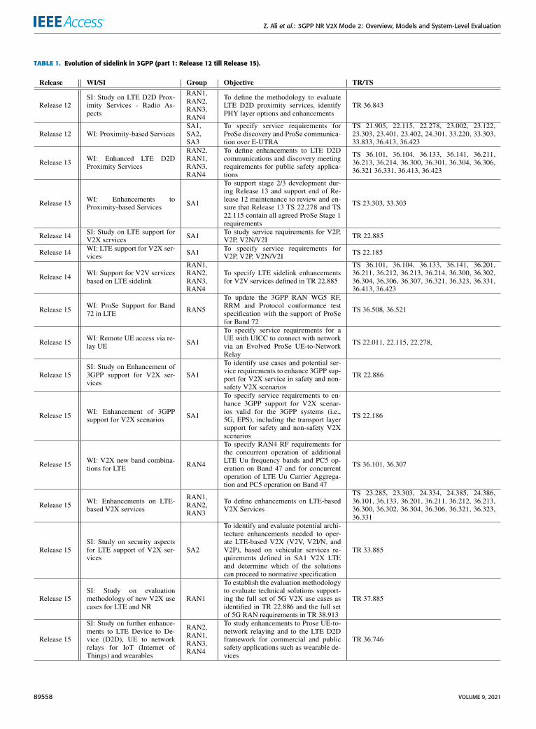
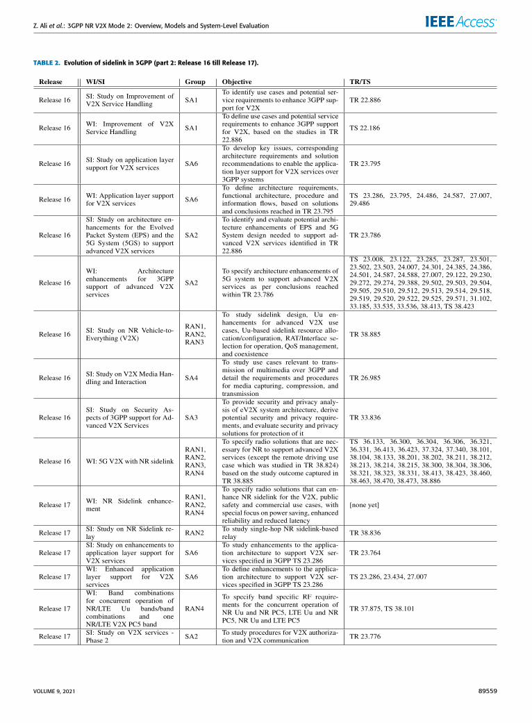
Tables 1 and 2 summarize the evolution of sidelinkcommunications in 3GPP, since its introduction with D2D(Release 12/13), through LTE C-V2X (Release 14/15) andup to date in NR V2X (Release 16/17), including various SIsand WIs related to sidelink communication studies and stan-dardization. For each SI/WI, we specify the 3GPP release,the working/leading group in charge of such SI/WI, the objec-tive of the SI/WI, the resulting TR for the case of SIs and theimpacted Technical Specification (TS) for the case of WIs.The history of sidelink is split into two tables. Table 1 coversfrom Release 12 until Release 15 and Table 2 covers theSIs/WIs from Release 16 until Release 17.
A. D2D (RELEASE 12)D2D has been defined as a support for Proximity Ser-vices (ProSe). D2D enables the quick exchange of dataover short distances via a direct link between nodes andintroduces a new interface, the PC5, between nodes. Thisoffers an efficient way to bypass the LTE base station(or Evolved Node B (eNB)) and offload the eNB traffic.Besides content sharing, a D2D UE can act as a relay foranother device with a poor connection to the eNB and,therefore, D2D can be used to extend cellular network cov-erage. Two modes have been defined for centralized and
distributed scheduling of UE transmissions, namely Mode 1and Mode 2. Centralized scheduling occurs at the eNB(in-coverage mode), whereas distributed scheduling is car-ried out by the D2D UEs themselves, with no need to bein the coverage area of an eNB (out-of-coverage mode).In Mode 1, the UEs are scheduled by the eNB over dedicatedradio resources for data transmission. In Mode 2, a UE canautonomously select a radio resource from a resource pool,which is either configured by the network or pre-configuredin the user device for its direct D2D communication overPC5 interface.
Both modes share the same resource allocation structure,in which the transmission of data is scheduled within theso-called sidelink control period. Within this period, a setof subframes are allocated for the Physical Sidelink ControlChannel (PSCCH) transmission and a different set of sub-frames are allocated for the Physical Sidelink Shared Channel(PSSCH). The corresponding PSCCH for a given PSSCH isalways sent before the PSSCH data. The PSCCH contains theSidelink Control Information (SCI), also called schedulingassignment, which is used by the receiver to identify the occu-pation of the PSSCH radio resources. In both modes, the SCIis configured in format 0, and it is transmitted twice using twodifferent subframes in which it occupies the same ResourceBlock (RB). The second transmission is needed to improvethe reliability of the SCI message delivery at the receiver dueto the lack of a feedback channel in sidelink communication.The receiver blindly detects the SCI by monitoring all possi-ble PSCCH resources. The transport block is transmitted fourtimes in four consecutive subframes within the resource pool.This allows the receiver UE to implement open loop HybridAutomatic Repeat Request (HARQ) by combining the fourredundancy versions of the transport block.
The operational principle of Modes 1 and 2 is bat-tery life improvement of mobile devices. Vehicular com-munications have, however, other constraints that cannotbe accommodated with D2D ProSe. Specifically, the highlatencies of D2D are not suitable for vehicular communica-tions, where packet delays or packet losses can have severeand life-threatening consequences. In terms of requirements,the maximum allowed latency varies between 20 ms and100 ms, depending on the application, with reliability from80 % to 95 % [7].
B. LTE C-V2X (RELEASE 14)3GPP Release 14 extended the D2D ProSe functionality byadding two new modes, Modes 3 and 4, for LTE C-V2Xconnectivity. Basic safety messages and event-triggered mes-sages are transmitted for collision avoidance. V2V mainlyenables cooperative automated driving. V2P establishes thecommunications protocol between vehicles and pedestriansfor pedestrian safety. V2I implies the communications withroadside units and allows to make information about localroad and traffic conditions readily available to vehicles.V2N enables commercial services by providing access to datastored in the Cloud.
VOLUME 9, 2021 89557
Z. Ali et al.: 3GPP NR V2X Mode 2: Overview, Models and System-Level Evaluation
TABLE 1. Evolution of sidelink in 3GPP (part 1: Release 12 till Release 15).
89558 VOLUME 9, 2021
Z. Ali et al.: 3GPP NR V2X Mode 2: Overview, Models and System-Level Evaluation
TABLE 2. Evolution of sidelink in 3GPP (part 2: Release 16 till Release 17).
VOLUME 9, 2021 89559
Z. Ali et al.: 3GPP NR V2X Mode 2: Overview, Models and System-Level Evaluation
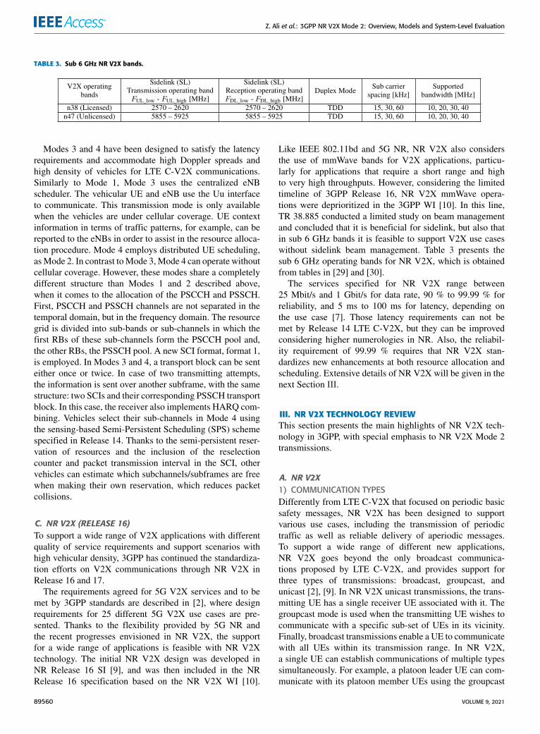
TABLE 3. Sub 6 GHz NR V2X bands.
Modes 3 and 4 have been designed to satisfy the latencyrequirements and accommodate high Doppler spreads andhigh density of vehicles for LTE C-V2X communications.Similarly to Mode 1, Mode 3 uses the centralized eNBscheduler. The vehicular UE and eNB use the Uu interfaceto communicate. This transmission mode is only availablewhen the vehicles are under cellular coverage. UE contextinformation in terms of traffic patterns, for example, can bereported to the eNBs in order to assist in the resource alloca-tion procedure. Mode 4 employs distributed UE scheduling,asMode 2. In contrast toMode 3,Mode 4 can operate withoutcellular coverage. However, these modes share a completelydifferent structure than Modes 1 and 2 described above,when it comes to the allocation of the PSCCH and PSSCH.First, PSCCH and PSSCH channels are not separated in thetemporal domain, but in the frequency domain. The resourcegrid is divided into sub-bands or sub-channels in which thefirst RBs of these sub-channels form the PSCCH pool and,the other RBs, the PSSCH pool. A new SCI format, format 1,is employed. In Modes 3 and 4, a transport block can be senteither once or twice. In case of two transmitting attempts,the information is sent over another subframe, with the samestructure: two SCIs and their corresponding PSSCH transportblock. In this case, the receiver also implements HARQ com-bining. Vehicles select their sub-channels in Mode 4 usingthe sensing-based Semi-Persistent Scheduling (SPS) schemespecified in Release 14. Thanks to the semi-persistent reser-vation of resources and the inclusion of the reselectioncounter and packet transmission interval in the SCI, othervehicles can estimate which subchannels/subframes are freewhen making their own reservation, which reduces packetcollisions.
C. NR V2X (RELEASE 16)To support a wide range of V2X applications with differentquality of service requirements and support scenarios withhigh vehicular density, 3GPP has continued the standardiza-tion efforts on V2X communications through NR V2X inRelease 16 and 17.
The requirements agreed for 5G V2X services and to bemet by 3GPP standards are described in [2], where designrequirements for 25 different 5G V2X use cases are pre-sented. Thanks to the flexibility provided by 5G NR andthe recent progresses envisioned in NR V2X, the supportfor a wide range of applications is feasible with NR V2Xtechnology. The initial NR V2X design was developed inNR Release 16 SI [9], and was then included in the NRRelease 16 specification based on the NR V2X WI [10].
Like IEEE 802.11bd and 5G NR, NR V2X also considersthe use of mmWave bands for V2X applications, particu-larly for applications that require a short range and highto very high throughputs. However, considering the limitedtimeline of 3GPP Release 16, NR V2X mmWave opera-tions were deprioritized in the 3GPP WI [10]. In this line,TR 38.885 conducted a limited study on beam managementand concluded that it is beneficial for sidelink, but also thatin sub 6 GHz bands it is feasible to support V2X use caseswithout sidelink beam management. Table 3 presents thesub 6 GHz operating bands for NR V2X, which is obtainedfrom tables in [29] and [30].
The services specified for NR V2X range between25 Mbit/s and 1 Gbit/s for data rate, 90 % to 99.99 % forreliability, and 5 ms to 100 ms for latency, depending onthe use case [7]. Those latency requirements can not bemet by Release 14 LTE C-V2X, but they can be improvedconsidering higher numerologies in NR. Also, the reliabil-ity requirement of 99.99 % requires that NR V2X stan-dardizes new enhancements at both resource allocation andscheduling. Extensive details of NR V2X will be given in thenext Section III.
III. NR V2X TECHNOLOGY REVIEWThis section presents the main highlights of NR V2X tech-nology in 3GPP, with special emphasis to NR V2X Mode 2transmissions.
A. NR V2X1) COMMUNICATION TYPESDifferently from LTE C-V2X that focused on periodic basicsafety messages, NR V2X has been designed to supportvarious use cases, including the transmission of periodictraffic as well as reliable delivery of aperiodic messages.To support a wide range of different new applications,NR V2X goes beyond the only broadcast communica-tions proposed by LTE C-V2X, and provides support forthree types of transmissions: broadcast, groupcast, andunicast [2], [9]. In NR V2X unicast transmissions, the trans-mitting UE has a single receiver UE associated with it. Thegroupcast mode is used when the transmitting UE wishes tocommunicate with a specific sub-set of UEs in its vicinity.Finally, broadcast transmissions enable a UE to communicatewith all UEs within its transmission range. In NR V2X,a single UE can establish communications of multiple typessimultaneously. For example, a platoon leader UE can com-municate with its platoon member UEs using the groupcast
89560 VOLUME 9, 2021
Z. Ali et al.: 3GPP NR V2X Mode 2: Overview, Models and System-Level Evaluation
mode, while using the broadcast mode to transmit other peri-odic messages to UEs that are not part of the platoon.
2) SIDELINK PHYSICAL CHANNELS AND REFERENCESIGNALSSidelink communications in NR V2X use the followingphysical channels [31]: 1) the Physical Sidelink BroadcastChannel (PSBCH) for sending broadcast information (likesynchronization of the sidelink), 2) the PSCCH for sendingcontrol information (1st-stage-SCI), 3) the PSSCH for send-ing control (2nd-stage-SCI), data and Channel State Informa-tion (CSI) in case of unicast, 4) and the Physical SidelinkFeedback Channel (PSFCH) for sending HARQ feedbackin case of unicast and groupcast modes. The PSFCH is anew channel, which was not previously considered in LTEC-V2X. For these channels, numerologies 0 (SCS=15 kHz),1 (SCS=30 kHz), and 2 (SCS=60 kHz) are supported atsub 6 GHz bands, and numerologies 2 (SCS=60 kHz) and3 (SCS=120 kHz) can be used at mmWave bands [32]. ForPSSCH, the supported modulation schemes include QPSK,16-QAM, 64-QAM, and 256-QAM. Instead, for PSCCH,only QPSK transmission is supported.
Regarding the reference signals, NR V2X uses [17]1) the Sidelink Primary/Secondary Synchronization Signal(S-PSS/S-SSS) for synchronization. S-PSS/S-SSS are trans-mitted together with the PSBCH in the so-called synchro-nization signal/PSBCH block (SSB). The SSB uses thesame numerology as the PSCCH/PSSCH on that carrier.2) Demodulation Reference Signals (DMRS) to estimatethe channel and perform data decoding. 3) Phase TrackingReference Signal (PT-RS) to compensate for phase noise.4) Channel State Information Reference Signal (CSI-RS) toestimate the channel and report channel quality information,similarly to NR.
3) SIDELINK RESOURCE POOLAn important aspect of sidelink communications is the def-inition of sidelink resource pools. In NR V2X, a UE canbe configured by higher layers with one or more sidelinkresource pools. A sidelink resource pool can be used fortransmission and reception of PSCCH/PSSCH, and can beassociated with either sidelink resource allocation Mode 1 orMode 2 [9]. In the frequency domain, a sidelink resourcepool consists of a number of contiguous subchannels [33].The size of each subchannel is fixed and it is composed ofN contiguous RBs. Both the number of subchannels and thesubchannel size are higher layer pre-configured, by RRC.NR V2X supports N = 10, 15, 20, 25, 50, 75, and 100RBs for possible sub-channel sizes [34]. In the time domain,the resources (i.e., slots) available for sidelink are determinedby repeating sidelink bitmaps. The bitmap is pre-configuredand characterized by a certain size. The resource pool param-eter from RRC, sl-TimeResource, defines the bitmap sizeand takes values 10, 11, 12, . . . , 160 [35]. In particular,in case of Time Division Duplex (TDD), the resourcesavailable for sidelink are given by the combination of
the TDD pattern and the sidelink bitmap. We also notethat, unlike LTE sidelink specification related to theTDDpattern and the size of sidelink bitmap [36], NR sidelinkspecification is flexible and any valid NR TDD pattern canbe used with any structure of a sidelink bitmap, which has asize specified by the standard [37]. Since NR V2X may bedeveloped both in a carrier dedicated to Intelligent TransportSystem (ITS) or to cellular services, the standards supportboth the cases where all the symbols in a slot are availablefor sidelink, or only a consecutive subset of them [9]. In ITSspectrum, all the symbols are always allocated to sidelink.Within the slots available for sidelink, the specificOrthogonalFrequency Division Multiplexing (OFDM) symbols used forsidelink transmission/reception are fixed and pre-configured.Two RRC parameters pre-configure the symbol index of thefirst symbol and the set of consecutive symbols in a slotavailable for sidelink [33].
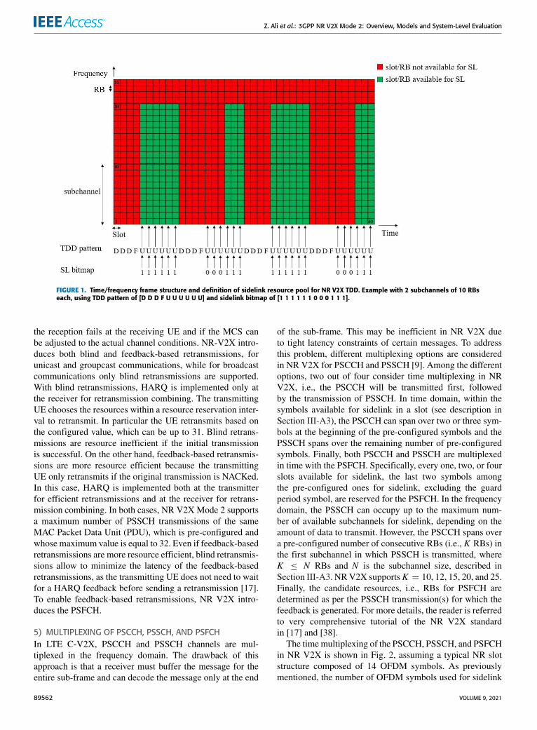
In Fig. 1 we illustrate the time/frequency frame structureof NR V2X and the definition of sidelink resource pools forTDD systems. The example is shown for the case of 10 MHzbandwidth using numerology 1 (i.e., SCS 30 kHz), and 2 sub-channels, each composed of 10RBswhere RB 1 is the startingRB of the first sidelink subchannel. In time, we consider aTDD pattern of [D D D F U U U U U U] (i.e., one downlinkslot, followed by a flexible slot,1 and three uplink slots), anda sidelink bitmap of [1 1 1 1 1 1 0 0 0 1 1 1]. As it can beobserved, the TDD pattern is repeated in time, and each indexof the sidelink bitmap applies to the uplink slots (U) in theTDD pattern, repeatedly, thus indicating the slots availablefor sidelink. In the frequency domain, a sidelink resourcepool consists of a number of contiguous subchannels [33],therefore, as per [35], the last 4 RBs are not available forsidelink. As a result, in the figure we illustrate in greenwhich slots/RBs are available for sidelink communicationsin the mentioned configuration example. This structure istypically used by an out-of-coverage NR V2X UE usingMode 2 operating in any of the V2X bands listed in Table 3.On the other hand, an in-coverage NR V2X UE operatingin either Mode 1 or Mode 2, will tailor its time/frequencystructure as per the next-Generation Node B (gNB) providedTDD pattern, sidelink bitmap, and subchannels.
4) RETRANSMISSIONS AND NEW SIDELINK FEEDBACKCHANNELDifferently from LTE C-V2X, which uses fixed MCS andonly provides support for blind retransmissions, i.e., thesource UE, automatically retransmits without knowing if theinitial transmission has been correctly received, NRV2X pro-vides different enhancements to improve reliability of com-munications, by introducing a feedback channel, the PSFCH.In particular, for unicast and groupcast communications con-sidered by NR V2X, but not by LTE C-V2X, reliability canbe improved if the source UE can retransmit the packet once
1The flexible slot is used to provide the necessary guard time for downlinkto uplink switching in TDD systems.
VOLUME 9, 2021 89561
Z. Ali et al.: 3GPP NR V2X Mode 2: Overview, Models and System-Level Evaluation
FIGURE 1. Time/frequency frame structure and definition of sidelink resource pool for NR V2X TDD. Example with 2 subchannels of 10 RBseach, using TDD pattern of [D D D F U U U U U U] and sidelink bitmap of [1 1 1 1 1 1 0 0 0 1 1 1].
the reception fails at the receiving UE and if the MCS canbe adjusted to the actual channel conditions. NR-V2X intro-duces both blind and feedback-based retransmissions, forunicast and groupcast communications, while for broadcastcommunications only blind retransmissions are supported.With blind retransmissions, HARQ is implemented only atthe receiver for retransmission combining. The transmittingUE chooses the resources within a resource reservation inter-val to retransmit. In particular the UE retransmits based onthe configured value, which can be up to 31. Blind retrans-missions are resource inefficient if the initial transmissionis successful. On the other hand, feedback-based retransmis-sions are more resource efficient because the transmittingUE only retransmits if the original transmission is NACKed.In this case, HARQ is implemented both at the transmitterfor efficient retransmissions and at the receiver for retrans-mission combining. In both cases, NR V2XMode 2 supportsa maximum number of PSSCH transmissions of the sameMAC Packet Data Unit (PDU), which is pre-configured andwhose maximum value is equal to 32. Even if feedback-basedretransmissions are more resource efficient, blind retransmis-sions allow to minimize the latency of the feedback-basedretransmissions, as the transmitting UE does not need to waitfor a HARQ feedback before sending a retransmission [17].To enable feedback-based retransmissions, NR V2X intro-duces the PSFCH.
5) MULTIPLEXING OF PSCCH, PSSCH, AND PSFCHIn LTE C-V2X, PSCCH and PSSCH channels are mul-tiplexed in the frequency domain. The drawback of thisapproach is that a receiver must buffer the message for theentire sub-frame and can decode the message only at the end
of the sub-frame. This may be inefficient in NR V2X dueto tight latency constraints of certain messages. To addressthis problem, different multiplexing options are consideredin NR V2X for PSCCH and PSSCH [9]. Among the differentoptions, two out of four consider time multiplexing in NRV2X, i.e., the PSCCH will be transmitted first, followedby the transmission of PSSCH. In time domain, within thesymbols available for sidelink in a slot (see description inSection III-A3), the PSCCH can span over two or three sym-bols at the beginning of the pre-configured symbols and thePSSCH spans over the remaining number of pre-configuredsymbols. Finally, both PSCCH and PSSCH are multiplexedin time with the PSFCH. Specifically, every one, two, or fourslots available for sidelink, the last two symbols amongthe pre-configured ones for sidelink, excluding the guardperiod symbol, are reserved for the PSFCH. In the frequencydomain, the PSSCH can occupy up to the maximum num-ber of available subchannels for sidelink, depending on theamount of data to transmit. However, the PSCCH spans overa pre-configured number of consecutive RBs (i.e., K RBs) inthe first subchannel in which PSSCH is transmitted, whereK ≤ N RBs and N is the subchannel size, described inSection III-A3. NRV2X supportsK = 10, 12, 15, 20, and 25.Finally, the candidate resources, i.e., RBs for PSFCH aredetermined as per the PSSCH transmission(s) for which thefeedback is generated. For more details, the reader is referredto very comprehensive tutorial of the NR V2X standardin [17] and [38].
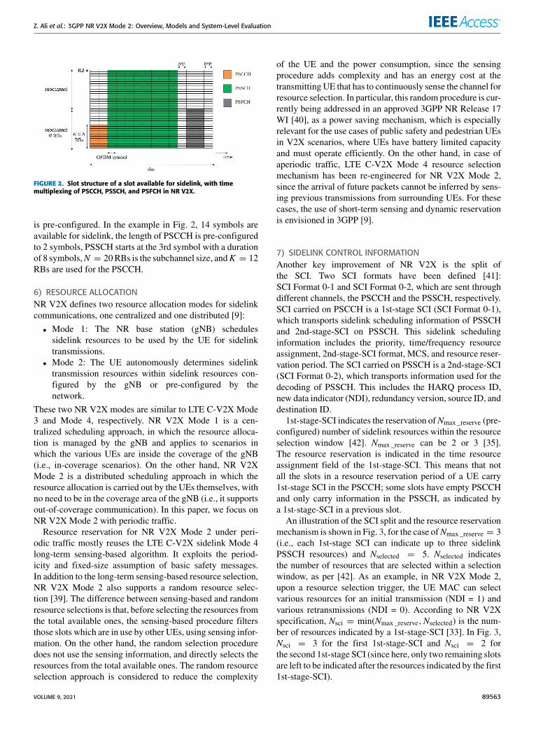
The timemultiplexing of the PSCCH, PSSCH, and PSFCHin NR V2X is shown in Fig. 2, assuming a typical NR slotstructure composed of 14 OFDM symbols. As previouslymentioned, the number of OFDM symbols used for sidelink
89562 VOLUME 9, 2021
Z. Ali et al.: 3GPP NR V2X Mode 2: Overview, Models and System-Level Evaluation
FIGURE 2. Slot structure of a slot available for sidelink, with timemultiplexing of PSCCH, PSSCH, and PSFCH in NR V2X.
is pre-configured. In the example in Fig. 2, 14 symbols areavailable for sidelink, the length of PSCCH is pre-configuredto 2 symbols, PSSCH starts at the 3rd symbol with a durationof 8 symbols,N = 20RBs is the subchannel size, andK = 12RBs are used for the PSCCH.
6) RESOURCE ALLOCATIONNR V2X defines two resource allocation modes for sidelinkcommunications, one centralized and one distributed [9]:
• Mode 1: The NR base station (gNB) schedulessidelink resources to be used by the UE for sidelinktransmissions.
• Mode 2: The UE autonomously determines sidelinktransmission resources within sidelink resources con-figured by the gNB or pre-configured by thenetwork.
These two NR V2X modes are similar to LTE C-V2X Mode3 and Mode 4, respectively. NR V2X Mode 1 is a cen-tralized scheduling approach, in which the resource alloca-tion is managed by the gNB and applies to scenarios inwhich the various UEs are inside the coverage of the gNB(i.e., in-coverage scenarios). On the other hand, NR V2XMode 2 is a distributed scheduling approach in which theresource allocation is carried out by the UEs themselves, withno need to be in the coverage area of the gNB (i.e., it supportsout-of-coverage communication). In this paper, we focus onNR V2X Mode 2 with periodic traffic.
Resource reservation for NR V2X Mode 2 under peri-odic traffic mostly reuses the LTE C-V2X sidelink Mode 4long-term sensing-based algorithm. It exploits the period-icity and fixed-size assumption of basic safety messages.In addition to the long-term sensing-based resource selection,NR V2X Mode 2 also supports a random resource selec-tion [39]. The difference between sensing-based and randomresource selections is that, before selecting the resources fromthe total available ones, the sensing-based procedure filtersthose slots which are in use by other UEs, using sensing infor-mation. On the other hand, the random selection proceduredoes not use the sensing information, and directly selects theresources from the total available ones. The random resourceselection approach is considered to reduce the complexity
of the UE and the power consumption, since the sensingprocedure adds complexity and has an energy cost at thetransmitting UE that has to continuously sense the channel forresource selection. In particular, this random procedure is cur-rently being addressed in an approved 3GPP NR Release 17WI [40], as a power saving mechanism, which is especiallyrelevant for the use cases of public safety and pedestrian UEsin V2X scenarios, where UEs have battery limited capacityand must operate efficiently. On the other hand, in case ofaperiodic traffic, LTE C-V2X Mode 4 resource selectionmechanism has been re-engineered for NR V2X Mode 2,since the arrival of future packets cannot be inferred by sens-ing previous transmissions from surrounding UEs. For thesecases, the use of short-term sensing and dynamic reservationis envisioned in 3GPP [9].
7) SIDELINK CONTROL INFORMATIONAnother key improvement of NR V2X is the split ofthe SCI. Two SCI formats have been defined [41]:SCI Format 0-1 and SCI Format 0-2, which are sent throughdifferent channels, the PSCCH and the PSSCH, respectively.SCI carried on PSCCH is a 1st-stage SCI (SCI Format 0-1),which transports sidelink scheduling information of PSSCHand 2nd-stage-SCI on PSSCH. This sidelink schedulinginformation includes the priority, time/frequency resourceassignment, 2nd-stage-SCI format, MCS, and resource reser-vation period. The SCI carried on PSSCH is a 2nd-stage-SCI(SCI Format 0-2), which transports information used for thedecoding of PSSCH. This includes the HARQ process ID,new data indicator (NDI), redundancy version, source ID, anddestination ID.
1st-stage-SCI indicates the reservation ofNmax _reserve (pre-configured) number of sidelink resources within the resourceselection window [42]. Nmax _reserve can be 2 or 3 [35].The resource reservation is indicated in the time resourceassignment field of the 1st-stage-SCI. This means that notall the slots in a resource reservation period of a UE carry1st-stage SCI in the PSCCH; some slots have empty PSCCHand only carry information in the PSSCH, as indicated bya 1st-stage-SCI in a previous slot.
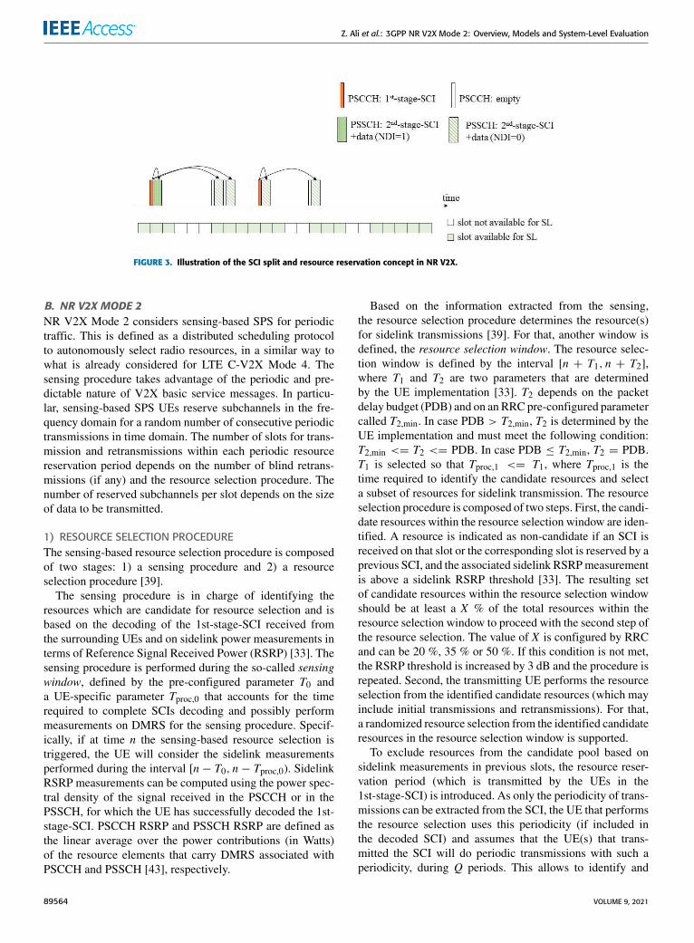
An illustration of the SCI split and the resource reservationmechanism is shown in Fig. 3, for the case ofNmax _reserve = 3(i.e., each 1st-stage SCI can indicate up to three sidelinkPSSCH resources) and Nselected = 5. Nselected indicatesthe number of resources that are selected within a selectionwindow, as per [42]. As an example, in NR V2X Mode 2,upon a resource selection trigger, the UE MAC can selectvarious resources for an initial transmission (NDI = 1) andvarious retransmissions (NDI = 0). According to NR V2Xspecification, Nsci = min(Nmax _reserve,Nselected) is the num-ber of resources indicated by a 1st-stage-SCI [33]. In Fig. 3,Nsci = 3 for the first 1st-stage-SCI and Nsci = 2 forthe second 1st-stage SCI (since here, only two remaining slotsare left to be indicated after the resources indicated by the first1st-stage-SCI).
VOLUME 9, 2021 89563
Z. Ali et al.: 3GPP NR V2X Mode 2: Overview, Models and System-Level Evaluation
FIGURE 3. Illustration of the SCI split and resource reservation concept in NR V2X.
B. NR V2X MODE 2NR V2X Mode 2 considers sensing-based SPS for periodictraffic. This is defined as a distributed scheduling protocolto autonomously select radio resources, in a similar way towhat is already considered for LTE C-V2X Mode 4. Thesensing procedure takes advantage of the periodic and pre-dictable nature of V2X basic service messages. In particu-lar, sensing-based SPS UEs reserve subchannels in the fre-quency domain for a random number of consecutive periodictransmissions in time domain. The number of slots for trans-mission and retransmissions within each periodic resourcereservation period depends on the number of blind retrans-missions (if any) and the resource selection procedure. Thenumber of reserved subchannels per slot depends on the sizeof data to be transmitted.
1) RESOURCE SELECTION PROCEDUREThe sensing-based resource selection procedure is composedof two stages: 1) a sensing procedure and 2) a resourceselection procedure [39].
The sensing procedure is in charge of identifying theresources which are candidate for resource selection and isbased on the decoding of the 1st-stage-SCI received fromthe surrounding UEs and on sidelink power measurements interms of Reference Signal Received Power (RSRP) [33]. Thesensing procedure is performed during the so-called sensingwindow, defined by the pre-configured parameter T0 anda UE-specific parameter Tproc,0 that accounts for the timerequired to complete SCIs decoding and possibly performmeasurements on DMRS for the sensing procedure. Specif-ically, if at time n the sensing-based resource selection istriggered, the UE will consider the sidelink measurementsperformed during the interval [n − T0, n − Tproc,0). SidelinkRSRP measurements can be computed using the power spec-tral density of the signal received in the PSCCH or in thePSSCH, for which the UE has successfully decoded the 1st-stage-SCI. PSCCH RSRP and PSSCH RSRP are defined asthe linear average over the power contributions (in Watts)of the resource elements that carry DMRS associated withPSCCH and PSSCH [43], respectively.
Based on the information extracted from the sensing,the resource selection procedure determines the resource(s)for sidelink transmissions [39]. For that, another window isdefined, the resource selection window. The resource selec-tion window is defined by the interval [n + T1, n + T2],where T1 and T2 are two parameters that are determinedby the UE implementation [33]. T2 depends on the packetdelay budget (PDB) and on an RRC pre-configured parametercalled T2,min. In case PDB > T2,min, T2 is determined by theUE implementation and must meet the following condition:T2,min <= T2 <= PDB. In case PDB ≤ T2,min, T2 = PDB.T1 is selected so that Tproc,1 <= T1, where Tproc,1 is thetime required to identify the candidate resources and selecta subset of resources for sidelink transmission. The resourceselection procedure is composed of two steps. First, the candi-date resources within the resource selection window are iden-tified. A resource is indicated as non-candidate if an SCI isreceived on that slot or the corresponding slot is reserved by aprevious SCI, and the associated sidelink RSRPmeasurementis above a sidelink RSRP threshold [33]. The resulting setof candidate resources within the resource selection windowshould be at least a X % of the total resources within theresource selection window to proceed with the second step ofthe resource selection. The value of X is configured by RRCand can be 20 %, 35 % or 50 %. If this condition is not met,the RSRP threshold is increased by 3 dB and the procedure isrepeated. Second, the transmitting UE performs the resourceselection from the identified candidate resources (which mayinclude initial transmissions and retransmissions). For that,a randomized resource selection from the identified candidateresources in the resource selection window is supported.
To exclude resources from the candidate pool based onsidelink measurements in previous slots, the resource reser-vation period (which is transmitted by the UEs in the1st-stage-SCI) is introduced. As only the periodicity of trans-missions can be extracted from the SCI, the UE that performsthe resource selection uses this periodicity (if included inthe decoded SCI) and assumes that the UE(s) that trans-mitted the SCI will do periodic transmissions with such aperiodicity, during Q periods. This allows to identify and
89564 VOLUME 9, 2021
Z. Ali et al.: 3GPP NR V2X Mode 2: Overview, Models and System-Level Evaluation
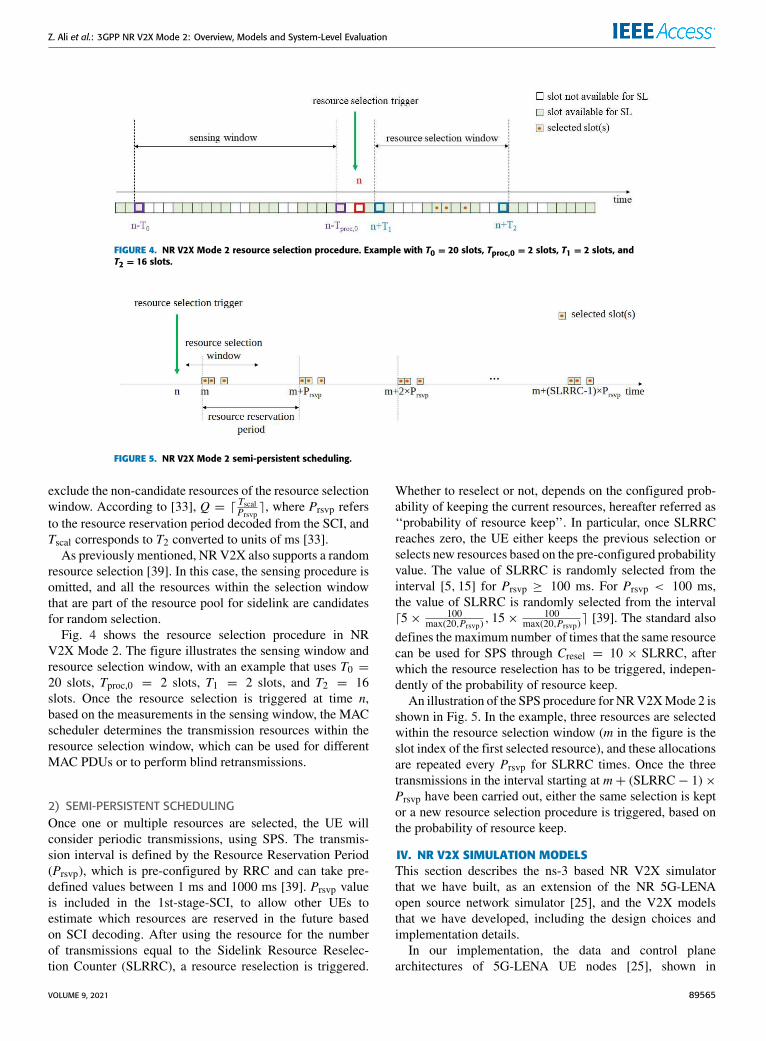
FIGURE 4. NR V2X Mode 2 resource selection procedure. Example with T0 = 20 slots, Tproc,0 = 2 slots, T1 = 2 slots, andT2 = 16 slots.
FIGURE 5. NR V2X Mode 2 semi-persistent scheduling.
exclude the non-candidate resources of the resource selectionwindow. According to [33], Q = d TscalPrsvp
e, where Prsvp refersto the resource reservation period decoded from the SCI, andTscal corresponds to T2 converted to units of ms [33].As previously mentioned, NR V2X also supports a random
resource selection [39]. In this case, the sensing procedure isomitted, and all the resources within the selection windowthat are part of the resource pool for sidelink are candidatesfor random selection.
Fig. 4 shows the resource selection procedure in NRV2X Mode 2. The figure illustrates the sensing window andresource selection window, with an example that uses T0 =20 slots, Tproc,0 = 2 slots, T1 = 2 slots, and T2 = 16slots. Once the resource selection is triggered at time n,based on the measurements in the sensing window, the MACscheduler determines the transmission resources within theresource selection window, which can be used for differentMAC PDUs or to perform blind retransmissions.
2) SEMI-PERSISTENT SCHEDULINGOnce one or multiple resources are selected, the UE willconsider periodic transmissions, using SPS. The transmis-sion interval is defined by the Resource Reservation Period(Prsvp), which is pre-configured by RRC and can take pre-defined values between 1 ms and 1000 ms [39]. Prsvp valueis included in the 1st-stage-SCI, to allow other UEs toestimate which resources are reserved in the future basedon SCI decoding. After using the resource for the numberof transmissions equal to the Sidelink Resource Reselec-tion Counter (SLRRC), a resource reselection is triggered.
Whether to reselect or not, depends on the configured prob-ability of keeping the current resources, hereafter referred as‘‘probability of resource keep’’. In particular, once SLRRCreaches zero, the UE either keeps the previous selection orselects new resources based on the pre-configured probabilityvalue. The value of SLRRC is randomly selected from theinterval [5, 15] for Prsvp ≥ 100 ms. For Prsvp < 100 ms,the value of SLRRC is randomly selected from the intervald5× 100
max(20,Prsvp), 15× 100
max(20,Prsvp)e [39]. The standard also
defines the maximum number of times that the same resourcecan be used for SPS through Cresel = 10 × SLRRC, afterwhich the resource reselection has to be triggered, indepen-dently of the probability of resource keep.
An illustration of the SPS procedure for NRV2XMode 2 isshown in Fig. 5. In the example, three resources are selectedwithin the resource selection window (m in the figure is theslot index of the first selected resource), and these allocationsare repeated every Prsvp for SLRRC times. Once the threetransmissions in the interval starting at m+ (SLRRC− 1)×Prsvp have been carried out, either the same selection is keptor a new resource selection procedure is triggered, based onthe probability of resource keep.
IV. NR V2X SIMULATION MODELSThis section describes the ns-3 based NR V2X simulatorthat we have built, as an extension of the NR 5G-LENAopen source network simulator [25], and the V2X modelsthat we have developed, including the design choices andimplementation details.
In our implementation, the data and control planearchitectures of 5G-LENA UE nodes [25], shown in
VOLUME 9, 2021 89565
Z. Ali et al.: 3GPP NR V2X Mode 2: Overview, Models and System-Level Evaluation
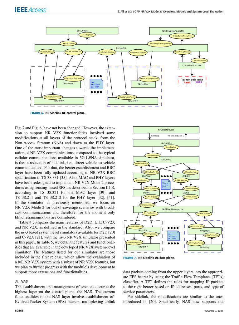
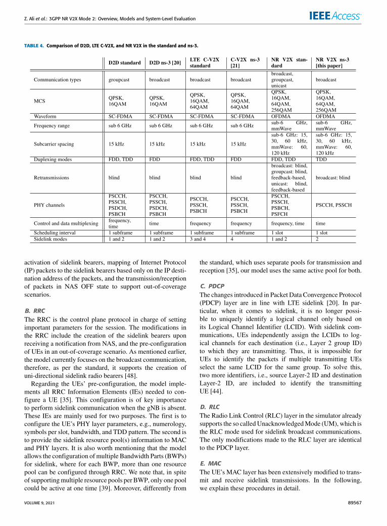
FIGURE 6. NR Sidelink UE control plane.
Fig. 7 and Fig. 6, have not been changed. However, the exten-sion to support NR V2X functionalities involved somemodifications at all layers of the protocol stack, from theNon-Access Stratum (NAS) and down to the PHY layer.One of the most important changes towards the implemen-tation of NR V2X communications, compared to the typicalcellular communications available in 5G-LENA simulator,is the introduction of sidelink, i.e., direct vehicle-to-vehiclecommunications. For that, the bearer establishment and RRClayer have been fully updated according to NR V2X RRCspecification in TS 38.331 [35]. Also, MAC and PHY layershave been redesigned to implement NR V2X Mode 2 proce-dures using sensing-based SPS, as described in Section III-B,according to TS 38.321 for the MAC layer [39], andTS 38.211 and TS 38.212 for the PHY layer [32], [41].In the simulator, as previously mentioned, we focus onNR V2X Mode 2 for out-of-coverage scenarios with broad-cast communications and therefore, for the moment onlyblind retransmissions are considered.
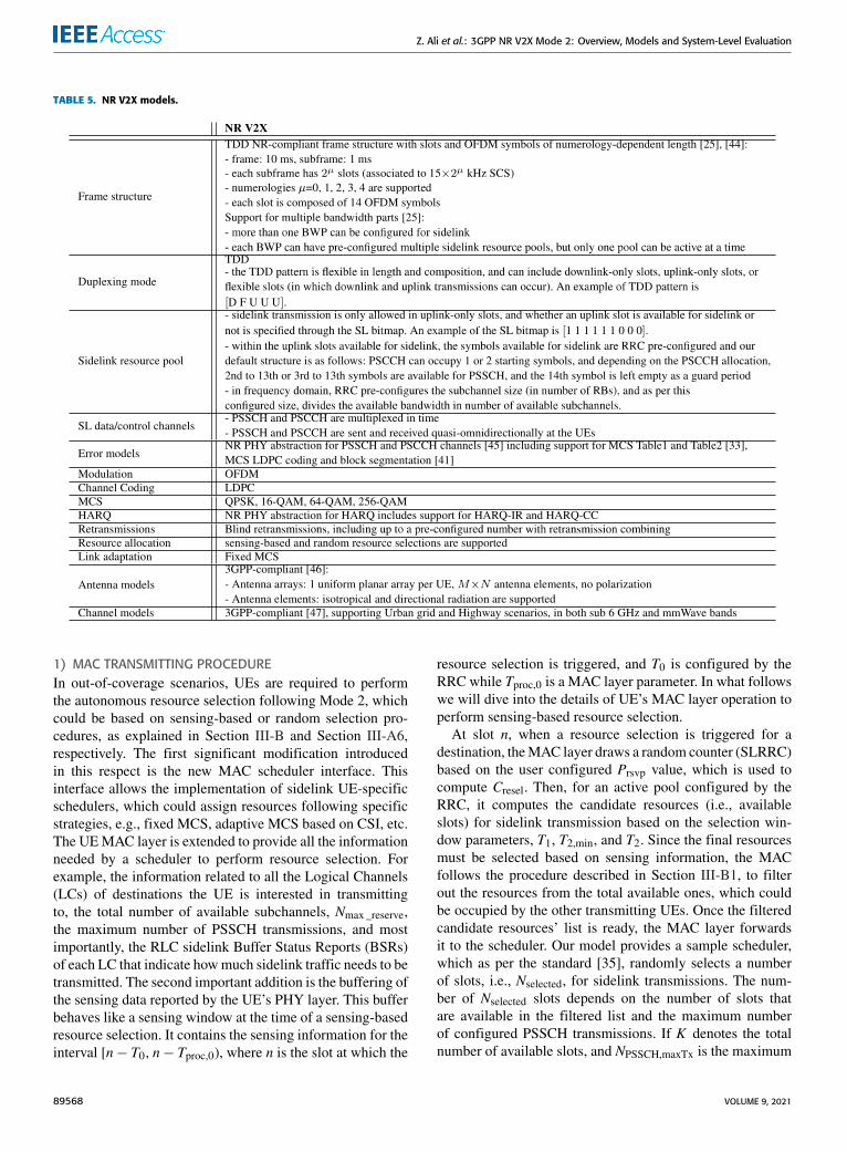
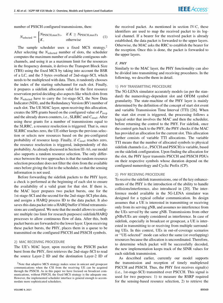
Table 4 compares the main features of D2D, LTE C-V2Xand NR V2X, as defined in the standard. Also, we comparethe ns-3 based system level simulators available for D2D [20]and C-V2X [21], with the ns-3 NR V2X simulator presentedin this paper. In Table 5, we detail the features and functional-ities that are available in the developed NRV2X system-levelsimulator. The features listed for our simulator are thoseincluded in the first release, which allow the evaluation ofa full NR V2X system with a subset of NR V2X features, butwe plan to further progress with the module’s development tosupport more extensions and functionalities.
A. NASThe establishment and management of sessions occur at thehighest layer on the control plane, the NAS. The currentfunctionalities of the NAS layer involve establishment ofEvolved Packet System (EPS) bearers, multiplexing uplink
FIGURE 7. NR Sidelink UE data plane.
data packets coming from the upper layers into the appropri-ate EPS bearer by using the Traffic Flow Templates (TFTs)classifier. A TFT defines the rules for mapping IP packetsto the right bearer based on IP addresses, ports, and type ofservice parameters.
For sidelink, the modifications are similar to the onesintroduced in [20]. Specifically, NAS now supports the
89566 VOLUME 9, 2021
Z. Ali et al.: 3GPP NR V2X Mode 2: Overview, Models and System-Level Evaluation
TABLE 4. Comparison of D2D, LTE C-V2X, and NR V2X in the standard and ns-3.
activation of sidelink bearers, mapping of Internet Protocol(IP) packets to the sidelink bearers based only on the IP desti-nation address of the packets, and the transmission/receptionof packets in NAS OFF state to support out-of-coveragescenarios.
B. RRCThe RRC is the control plane protocol in charge of settingimportant parameters for the session. The modifications inthe RRC include the creation of the sidelink bearers uponreceiving a notification from NAS, and the pre-configurationof UEs in an out-of-coverage scenario. As mentioned earlier,the model currently focuses on the broadcast communication,therefore, as per the standard, it supports the creation ofuni-directional sidelink radio bearers [48].
Regarding the UEs’ pre-configuration, the model imple-ments all RRC Information Elements (IEs) needed to con-figure a UE [35]. This configuration is of key importanceto perform sidelink communication when the gNB is absent.These IEs are mainly used for two purposes. The first is toconfigure the UE’s PHY layer parameters, e.g., numerology,symbols per slot, bandwidth, and TDD pattern. The second isto provide the sidelink resource pool(s) information to MACand PHY layers. It is also worth mentioning that the modelallows the configuration of multiple Bandwidth Parts (BWPs)for sidelink, where for each BWP, more than one resourcepool can be configured through RRC. We note that, in spiteof supportingmultiple resource pools per BWP, only one poolcould be active at one time [39]. Moreover, differently from
the standard, which uses separate pools for transmission andreception [35], our model uses the same active pool for both.
C. PDCPThe changes introduced in Packet Data Convergence Protocol(PDCP) layer are in line with LTE sidelink [20]. In par-ticular, when it comes to sidelink, it is no longer possi-ble to uniquely identify a logical channel only based onits Logical Channel Identifier (LCID). With sidelink com-munications, UEs independently assign the LCIDs to log-ical channels for each destination (i.e., Layer 2 group ID)to which they are transmitting. Thus, it is impossible forUEs to identify the packets if multiple transmitting UEsselect the same LCID for the same group. To solve this,two more identifiers, i.e., source Layer-2 ID and destinationLayer-2 ID, are included to identify the transmittingUE [44].
D. RLCThe Radio Link Control (RLC) layer in the simulator alreadysupports the so calledUnacknowledgedMode (UM), which isthe RLC mode used for sidelink broadcast communications.The only modifications made to the RLC layer are identicalto the PDCP layer.
E. MACThe UE’s MAC layer has been extensively modified to trans-mit and receive sidelink transmissions. In the following,we explain these procedures in detail.
VOLUME 9, 2021 89567
Z. Ali et al.: 3GPP NR V2X Mode 2: Overview, Models and System-Level Evaluation
TABLE 5. NR V2X models.
1) MAC TRANSMITTING PROCEDUREIn out-of-coverage scenarios, UEs are required to performthe autonomous resource selection following Mode 2, whichcould be based on sensing-based or random selection pro-cedures, as explained in Section III-B and Section III-A6,respectively. The first significant modification introducedin this respect is the new MAC scheduler interface. Thisinterface allows the implementation of sidelink UE-specificschedulers, which could assign resources following specificstrategies, e.g., fixed MCS, adaptive MCS based on CSI, etc.The UEMAC layer is extended to provide all the informationneeded by a scheduler to perform resource selection. Forexample, the information related to all the Logical Channels(LCs) of destinations the UE is interested in transmittingto, the total number of available subchannels, Nmax _reserve,the maximum number of PSSCH transmissions, and mostimportantly, the RLC sidelink Buffer Status Reports (BSRs)of each LC that indicate howmuch sidelink traffic needs to betransmitted. The second important addition is the buffering ofthe sensing data reported by the UE’s PHY layer. This bufferbehaves like a sensing window at the time of a sensing-basedresource selection. It contains the sensing information for theinterval [n− T0, n− Tproc,0), where n is the slot at which the
resource selection is triggered, and T0 is configured by theRRC while Tproc,0 is a MAC layer parameter. In what followswe will dive into the details of UE’s MAC layer operation toperform sensing-based resource selection.
At slot n, when a resource selection is triggered for adestination, theMAC layer draws a random counter (SLRRC)based on the user configured Prsvp value, which is used tocompute Cresel. Then, for an active pool configured by theRRC, it computes the candidate resources (i.e., availableslots) for sidelink transmission based on the selection win-dow parameters, T1, T2,min, and T2. Since the final resourcesmust be selected based on sensing information, the MACfollows the procedure described in Section III-B1, to filterout the resources from the total available ones, which couldbe occupied by the other transmitting UEs. Once the filteredcandidate resources’ list is ready, the MAC layer forwardsit to the scheduler. Our model provides a sample scheduler,which as per the standard [35], randomly selects a numberof slots, i.e., Nselected, for sidelink transmissions. The num-ber of Nselected slots depends on the number of slots thatare available in the filtered list and the maximum numberof configured PSSCH transmissions. If K denotes the totalnumber of available slots, and NPSSCH,maxTx is the maximum
89568 VOLUME 9, 2021
Z. Ali et al.: 3GPP NR V2X Mode 2: Overview, Models and System-Level Evaluation
number of PSSCH configured transmissions, then:
Nselected =
{NPSSCH,maxTx, if K ≥ NPSSCH,maxTx
K , otherwise(1)
The sample scheduler uses a fixed MCS strategy.2
After selecting the Nselected number of slots, the schedulercomputes the maximum number of available contiguous sub-channels, and using it as a maximum limit for the resourcesin the frequency domain, it derives the Transport Block Size(TBS) using the fixed MCS by taking into account the BSRof a LC, and the 5 bytes overhead of 2nd-stage-SCI, whichneeds to be multiplexed with data. Then, it randomly choosesthe index of the starting subchannel for each slot. Finally,it prepares a sidelink allocation valid for the first resourcereservation period deciding also aspects like which slots fromthe Nselected have to carry the 1st-stage-SCI, the New DataIndicator (NDI), and the RedundancyVersion (RV) number ofeach slot. The UE MAC layer, upon receiving this allocation,creates the SPS grants based on the configured value of Prsvpand the already drawn counters, i.e., SLRRC and Cresel. Afterusing these grants for a number of transmissions equal tothe SLRRC, a resource reselection is triggered. That is, onceSLRRC reaches zero, the UE either keeps the previous selec-tion or selects new resources based on the pre-configuredprobability of resource keep. Finally, if Cresel reaches zero,the resource reselection is triggered, independently of thisprobability. As already discussed in Section III-A6, ourmodelalso supports a random resource selection. The only differ-ence between the two approaches is that the random resourceselection procedure does not filter the slots from the availableones before giving the list to the scheduler, so that the sensinginformation is not used.
Before forwarding the sidelink packets to the PHY layer,a check is performed at the beginning of each slot to ensurethe availability of a valid grant for that slot. If there is,the MAC layer prepares two packet bursts, one for the1st-stage-SCI and the second for the 2nd-stage-SCI plus data,and assigns a HARQ process ID to the data packet. It alsosaves this data packet into a HARQ buffer if blind retransmis-sions are configured.We note that the model allows to config-ure multiple (no limit for research purposes) sidelink/HARQprocesses to allow continuous flow of data. After this, bothpacket bursts are forwarded to the lower layer. Upon receivingthese packet bursts, the PHY, places them in a queue to betransmitted on the configured PSCCH and PSSCH symbols.
2) MAC RECEIVING PROCEDUREThe UE’s MAC layer, upon receiving the PSSCH packetburst from the PHY, first retrieves the 2nd-stage-SCI to readthe source Layer-2 ID and the destination Layer-2 ID of
2Note that adaptive MCS strategy makes sense in unicast and groupcastcommunications when the CSI from the receiving UE can be acquiredthrough the PSSCH. As in this paper we have focused on broadcast com-munications, without PSFCH, the fixed MCS strategy is the adequate one.However, the implemented scheduler interface is general enough to accom-modate more sophisticated schedulers.
the received packet. As mentioned in section IV-C, theseidentifiers are used to map the received packet to its log-ical channel. If a bearer for the received packet is alreadyestablished, the data packet is forwarded to the upper layers.Otherwise, the MAC asks the RRC to establish the bearer forthe reception. Once this is done, the packet is forwarded tothe upper layers.
F. PHYSimilarly to the MAC layer, the PHY functionality can alsobe divided into transmitting and receiving procedures. In thefollowing, we describe them in detail.
1) PHY TRANSMITTING PROCEDUREThe 5G-LENA simulator accurately models (as per the stan-dard) the numerology-dependent slot and OFDM symbolgranularity. The state-machine of the PHY layer is mainlydetermined by the definition of the concept of start slot eventand variable Transmission Time Interval (TTI) [26]. Whenthe start slot event is triggered, the processing follows alogical order that involves the MAC and then the scheduler,before returning the control to the PHY. For sidelink, oncethe control gets back to the PHY, the PHY checks if the MAChas provided an allocation for the current slot. This allocationfurther consists of variable TTI allocations. The variableTTI means that the number of allocated symbols to physicalsidelink channels (i.e., PSCCH and PSSCH) is variable, basedon the sidelink configuration. Upon finding the allocation forthe slot, the PHY layer transmits PSCCH and PSSCH PDUson their respective symbols whose duration depend on theconfigured numerology and Cyclic Prefix (CP).
2) PHY RECEIVING PROCEDURETo receive the sidelink transmissions, one of the key enhance-ments of the PHY is the introduction of the ability to handlecollisions/interference, also introduced in [20]. The inter-ference model available in the 5G-LENA simulator wasdesigned for a typical cellular communication. Its designassumes that a UE is interested in transmitting or receivingonly from its serving gNB, and assumes no interference fromthe UEs served by the same gNB. Transmissions from othergNBs/UEs are simply considered as interference. In case ofsidelink, especially in broadcast or groupcast, a UE is inter-ested in transmitting to or receiving from multiple surround-ing UEs. In this context, UEs in out-of-coverage scenariosor ‘‘UE-selected’’ mode can select the same (or overlapping)resources because the allocation is uncoordinated. Therefore,to determine which packet will be successfully decoded,the new implementation keeps track of the SINR values foreach sidelink transmission.
As described earlier, currently our model supportsthe transmission and reception of timely multiplexedPSCCH and PSSCH. Thus, the PHY first receives signal(s)(i.e., 1st-stage-SCI) transmitted over PSCCH. This signal isused for two purposes: 1) to measure the RSRP requiredfor the sensing-based resource selection, 2) to retrieve the
VOLUME 9, 2021 89569
Z. Ali et al.: 3GPP NR V2X Mode 2: Overview, Models and System-Level Evaluation
information about the possible PSSCH transmission andretransmissions. The RSRP is computed using the 3 ResourceElements (REs) per RBs, carrying the 1st-stage-SCI, sincethe simulator does not explicitly include PSCCH DMRS.Moreover, for the sensing-based resource selection, the PHYmeasures the RSRP of each correctly decoded 1st-stage-SCI, from all the surrounding UEs. On the other hand,after computing the RSRP, if it is from the transmitterof interest, it reads the information encoded in the 1st-stage-SCI to receive the PSSCH transmission and its possibleretransmissions.
Concerning the error model used for the reception ofPSCCH and PSSCH transmission, we use the existing dataplane error model in 5G-LENA [45], since the MCSsdefined for PSSCH are the same as the ones defined forPDSCH/PUSCH. Also, we adopt such an error model for thePSCCH, using MCS0.
G. CHANNEL MODELSTR 37.885 [47] defines the system-level evaluation method-ology for 5G V2X use cases, including the descrip-tion and modeling of scenarios, deployment, mobility,antenna, traffic, and channel models. For channel modeling,TR 37.885 extends the geometry-based stochastic channelmodeling framework introduced in TR 38.901 [49] for typicalcellular communications, by adding the possibility to modelwireless channel in vehicular environments and sidelink com-munications in which both the transmitter and the receiverare in motion. Two key scenarios are used for NR V2Xevaluation [47]:
• Urban grid, which targets urban environments with agrid of buildings and roads with four lanes (two in eachdirection) between the buildings, and
• Highway, which targets highway environments with ahighway composed of a total of six lanes, consideringthree lanes in each opposite direction.
For each scenario, TR 37.885 specifies new channel condi-tion models, propagation models, and fast fading parameterscapturing the characteristics of each environment.
The developed ns-3 NR V2X module includes the channeland antenna models for both V2X Urban grid and Highwayscenarios, as defined in [47].
V. NR V2X EVALUATION CAMPAIGNSThis section presents the simulation scenario that we haveused to assess NR V2X performance. Then, we presentmultiple simulation campaigns and discuss the obtained end-to-end results.
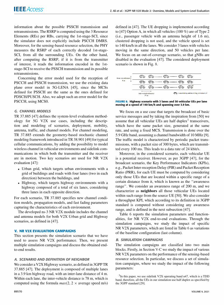
A. SCENARIO AND DEFINITION OF NEIGHBORWeconsider aV2XHighway scenario, as defined in 3GPPTR37.885 [47]. The deployment is composed of multiple lanesin a 3.9 km highway road, with an inter-lane distance of 4 m.Within each lane, the inter-vehicle distance is 78 m, which iscomputed using the formula max(2, 2 × average speed m/s)
defined in [47]. The UE dropping is implemented accordingto [47] Option A, in which all vehicles (100 %) are of Type 2(i.e., passenger vehicle with an antenna height of 1.6 m),clustered dropping is not used, and the vehicle speed is setto 140 km/h in all the lanes.We consider 3 lanes with vehiclesmoving in the same direction, and 50 vehicles per lane.We focus on an out-of-coverage scenario, so that gNBs aredisabled in the evaluation [47]. The considered deploymentscenario is shown in Fig. 8.
FIGURE 8. Highway scenario with 3 lanes and 50 vehicular UEs per lanemoving at a speed of 140 km/h and spanning over 3.9 km.
We focus on a use case that targets the broadcast of basicservice messages and by taking the inspiration from [50] weassume that all vehicular UEs are half duplex3 transceivers,which have the same packet size, generated at the samerate, and using a fixed MCS. Transmission is done over the5.9 GHz band, assuming a channel bandwidth of 10MHz [9].The traffic model is characterized by periodic packet trans-missions, with a packet size of 300 bytes, which are transmit-ted every 100 ms. This leads to a data rate of 24 kbit/s.
Moreover, in the considered scenario, each vehicular UEis a potential receiver. However, as per 3GPP [47], for thebroadcast scenario, the Key Performance Indicators (KPIs),e.g., Packet Inter-receptionDelay (PIR) and Packet ReceptionRatio (PRR), for each UE must be computed by consideringonly those UEs that are located within a specific range of acertain distance from it, which is known as the ‘‘awarenessrange’’. We consider an awareness range of 200 m, and wecharacterize as neighbors all those vehicular UEs locatedwithin such range from the source UE [50]. We also considera throughput KPI, which according to its definition in 3GPPstandard is computed without considering any awarenessrange, and is defined in the next subsection [47].
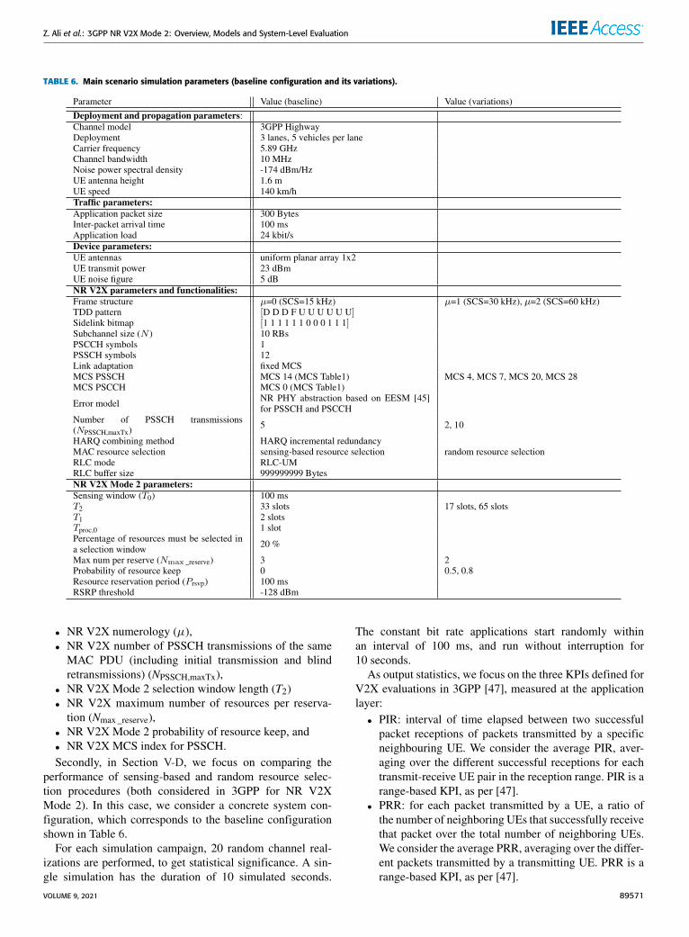
Table 6 reports the simulation parameters and function-alities, for NR V2X end-to-end evaluations. Through thesimulation campaigns, we study the impact of specificNR V2X parameters, which are listed in Table 6 as variationsof the baseline configuration (last column).
B. SIMULATION CAMPAIGNSThe simulation campaigns are classified into two mainblocks. Firstly, in Section V-C we study the impact of variousNRV2X parameters on the performance of the sensing-basedresource selection. In particular, we discuss a set of simula-tion campaigns, where we study the impact of the followingparameters:
3In this paper, we use sidelink V2X operating band n47, which is a TDDband, therefore, all the UEs in our simulation use half duplex as specified bythe 3GPP standard [29].
89570 VOLUME 9, 2021
Z. Ali et al.: 3GPP NR V2X Mode 2: Overview, Models and System-Level Evaluation
TABLE 6. Main scenario simulation parameters (baseline configuration and its variations).
• NR V2X numerology (µ),• NR V2X number of PSSCH transmissions of the sameMAC PDU (including initial transmission and blindretransmissions) (NPSSCH,maxTx),
• NR V2X Mode 2 selection window length (T2)• NR V2X maximum number of resources per reserva-tion (Nmax _reserve),
• NR V2X Mode 2 probability of resource keep, and• NR V2X MCS index for PSSCH.Secondly, in Section V-D, we focus on comparing the
performance of sensing-based and random resource selec-tion procedures (both considered in 3GPP for NR V2XMode 2). In this case, we consider a concrete system con-figuration, which corresponds to the baseline configurationshown in Table 6.
For each simulation campaign, 20 random channel real-izations are performed, to get statistical significance. A sin-gle simulation has the duration of 10 simulated seconds.
The constant bit rate applications start randomly withinan interval of 100 ms, and run without interruption for10 seconds.
As output statistics, we focus on the three KPIs defined forV2X evaluations in 3GPP [47], measured at the applicationlayer:• PIR: interval of time elapsed between two successfulpacket receptions of packets transmitted by a specificneighbouring UE. We consider the average PIR, aver-aging over the different successful receptions for eachtransmit-receive UE pair in the reception range. PIR is arange-based KPI, as per [47].
• PRR: for each packet transmitted by a UE, a ratio ofthe number of neighboring UEs that successfully receivethat packet over the total number of neighboring UEs.We consider the average PRR, averaging over the differ-ent packets transmitted by a transmitting UE. PRR is arange-based KPI, as per [47].
VOLUME 9, 2021 89571
Z. Ali et al.: 3GPP NR V2X Mode 2: Overview, Models and System-Level Evaluation
• Throughput: total number of correctly received bytesover the simulation time, measured at the applicationlayer, for each transmit-receive UE pair. As per [47],throughput is not range-based, so we consider allthroughput values for those UEs that received some databytes.
For each of the output statistics, we represent the Cumu-lative Distribution Function (CDF), over the different sim-ulation runs. For each simulation campaign, we show threefigures, one for each of the above mentioned output statistics,i.e., (a) PIR, (b) PRR, (c) throughput.
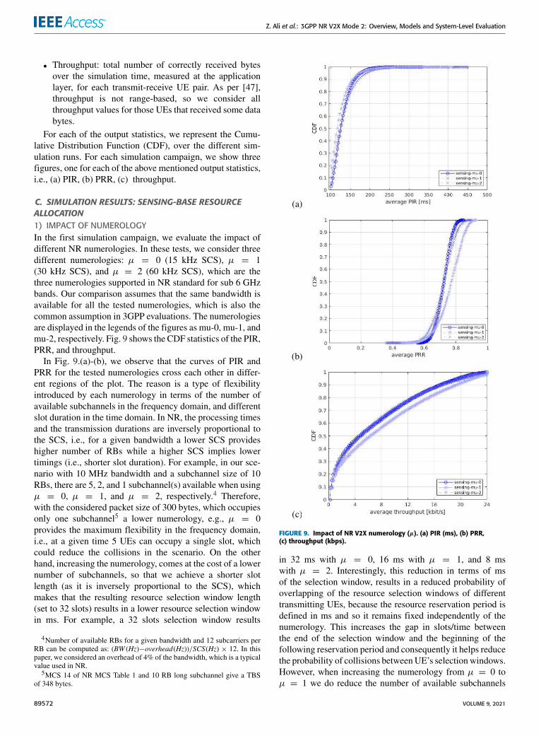
C. SIMULATION RESULTS: SENSING-BASE RESOURCEALLOCATION1) IMPACT OF NUMEROLOGYIn the first simulation campaign, we evaluate the impact ofdifferent NR numerologies. In these tests, we consider threedifferent numerologies: µ = 0 (15 kHz SCS), µ = 1(30 kHz SCS), and µ = 2 (60 kHz SCS), which are thethree numerologies supported in NR standard for sub 6 GHzbands. Our comparison assumes that the same bandwidth isavailable for all the tested numerologies, which is also thecommon assumption in 3GPP evaluations. The numerologiesare displayed in the legends of the figures as mu-0, mu-1, andmu-2, respectively. Fig. 9 shows the CDF statistics of the PIR,PRR, and throughput.
In Fig. 9.(a)-(b), we observe that the curves of PIR andPRR for the tested numerologies cross each other in differ-ent regions of the plot. The reason is a type of flexibilityintroduced by each numerology in terms of the number ofavailable subchannels in the frequency domain, and differentslot duration in the time domain. In NR, the processing timesand the transmission durations are inversely proportional tothe SCS, i.e., for a given bandwidth a lower SCS provideshigher number of RBs while a higher SCS implies lowertimings (i.e., shorter slot duration). For example, in our sce-nario with 10 MHz bandwidth and a subchannel size of 10RBs, there are 5, 2, and 1 subchannel(s) available when usingµ = 0, µ = 1, and µ = 2, respectively.4 Therefore,with the considered packet size of 300 bytes, which occupiesonly one subchannel5 a lower numerology, e.g., µ = 0provides the maximum flexibility in the frequency domain,i.e., at a given time 5 UEs can occupy a single slot, whichcould reduce the collisions in the scenario. On the otherhand, increasing the numerology, comes at the cost of a lowernumber of subchannels, so that we achieve a shorter slotlength (as it is inversely proportional to the SCS), whichmakes that the resulting resource selection window length(set to 32 slots) results in a lower resource selection windowin ms. For example, a 32 slots selection window results
4Number of available RBs for a given bandwidth and 12 subcarriers perRB can be computed as: (BW (Hz)−overhead(Hz))/SCS(Hz) × 12. In thispaper, we considered an overhead of 4% of the bandwidth, which is a typicalvalue used in NR.
5MCS 14 of NR MCS Table 1 and 10 RB long subchannel give a TBSof 348 bytes.
FIGURE 9. Impact of NR V2X numerology (µ). (a) PIR (ms), (b) PRR,(c) throughput (kbps).
in 32 ms with µ = 0, 16 ms with µ = 1, and 8 mswith µ = 2. Interestingly, this reduction in terms of msof the selection window, results in a reduced probability ofoverlapping of the resource selection windows of differenttransmitting UEs, because the resource reservation period isdefined in ms and so it remains fixed independently of thenumerology. This increases the gap in slots/time betweenthe end of the selection window and the beginning of thefollowing reservation period and consequently it helps reducethe probability of collisions betweenUE’s selectionwindows.However, when increasing the numerology from µ = 0 toµ = 1 we do reduce the number of available subchannels
89572 VOLUME 9, 2021
Z. Ali et al.: 3GPP NR V2X Mode 2: Overview, Models and System-Level Evaluation
from 5 to 2 but we are also halving the selection windowfrom 32 ms to 16 ms, which results in a very similar per-formance. In fact, having more subchannels with µ = 0increases the PRR for some UEs thanks to the fact that UEscan better exploit diversity in frequency domain (see the tailof the PRR in Fig. 9.(b)). In this sense, we observe that forthe tested scenario reducing the selection window length tohalf is not enough to achieve an appreciable performancegain. Differently, when the numerology is further increasedto µ = 2, we can observe a performance gain achieved as aconsequence of a lower selectionwindow of 8ms (i.e., 4 timeslower than µ = 0) as it is clearly shown in Fig. 9.(b)-(c). It isimportant to note that, even if the resource selection is basedon sensing, the procedure requires that 20 % of the resourcesavailable for SL are candidates to perform a resource selec-tion. If this requirement is not fulfilled, the RSRP threshold isincreased by 3 dB until this condition is met. Because of that,collisions can still occur. Ultimately, the number of incorrectPSSCH receptions may imply packet losses, if they cannot berecovered by HARQ. This is effectively observed in the PRRand PIR statistics (see Fig. 9.(a)-(b)), for which, again,µ = 2is observed to offer better performance, as it allows reducedpacket collisions and a larger number of successfully decodedpackets, as a consequence of the shorter slot duration.
All in all, the trade-off of having more subchannels witha lower numerology versus a lower resource selection win-dow length with higher numerology results in comparableperformance when using the three numerologies. However,using µ = 2 results in a lower slot duration and helps moreUEs to achieve higher PRR, higher throughput, and lowerPIR (which appears due to a lower probability of overlappingresource selection windows of different transmitting UEs)compared to µ = 0 and µ = 1.
2) IMPACT OF NUMBER OF PSSCH TRANSMISSIONSIn the second simulation campaign, we assess the impact ofusing different numbers of PSSCH transmissions of the sameMAC PDU. This parameter is also known as NPSSCH,maxTxand, in case of SPS with blind retransmissions, it correspondsto the maximum possible number of resources that can beselected by the resource selection procedure. In our tests,we use NPSSCH,maxTx = 2, 5, and 10. This includes one initialtransmission and NPSSCH,maxTx − 1 blind retransmissions.They are displayed in the legends of the figures as retx-2,retx-5, and retx-10, respectively. Fig. 10 shows the CDFstatistics of the PIR, PRR, and throughput.
As shown in Fig. 10, a lower number of PSSCH transmis-sions is beneficial in terms of all the performance indicators.The reason is that in the considered scenario, characterizedby good propagation conditions, a lower NPSSCH,maxTx doesnot saturate the resources, which helps the sensing-based pro-cedure at the transmitting UEs to fully exploit the flexibilityin terms of the number of subchannels, i.e., 5 subchannels tochoose from at each slot. After properly filtering the resourcesbased on sensing, a lower NPSSCH,maxTx, offers an improve-ment in PIR, PRR, and throughput compared to higher values
FIGURE 10. Impact of NR V2X number of PSSCH transmissions of thesame MAC PDU (NPSSCH,maxTx). (a) PIR (ms), (b) PRR,(c) throughput (kbps).
of NPSSCH,maxTx, which is due to the fact that the sensingprocedure is properly avoiding collisions and a small numberof PSSCH transmissions is enough to decode the packetsbecause of the good propagation conditions. This definitelydemonstrates the effectiveness of the sensing-based resourceselection in vehicular scenarios.
In summary, in a scenario with good propagation con-ditions where it is likely that UEs are able to sense eachother, a low number of PSSCH transmissions shows betterperformance for all the indicators when using sensing-basedresource selection. The result changes when sensing is not
VOLUME 9, 2021 89573
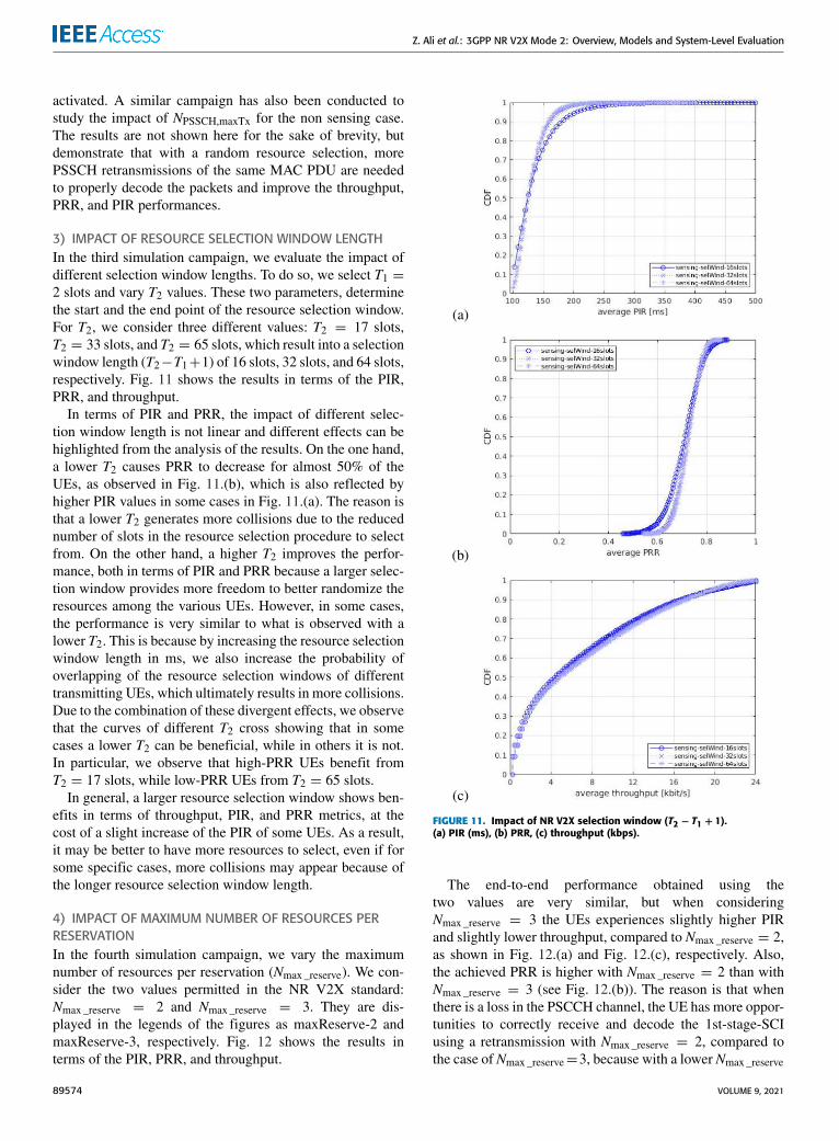
Z. Ali et al.: 3GPP NR V2X Mode 2: Overview, Models and System-Level Evaluation
activated. A similar campaign has also been conducted tostudy the impact of NPSSCH,maxTx for the non sensing case.The results are not shown here for the sake of brevity, butdemonstrate that with a random resource selection, morePSSCH retransmissions of the same MAC PDU are neededto properly decode the packets and improve the throughput,PRR, and PIR performances.
3) IMPACT OF RESOURCE SELECTION WINDOW LENGTHIn the third simulation campaign, we evaluate the impact ofdifferent selection window lengths. To do so, we select T1 =2 slots and vary T2 values. These two parameters, determinethe start and the end point of the resource selection window.For T2, we consider three different values: T2 = 17 slots,T2 = 33 slots, and T2 = 65 slots, which result into a selectionwindow length (T2−T1+1) of 16 slots, 32 slots, and 64 slots,respectively. Fig. 11 shows the results in terms of the PIR,PRR, and throughput.
In terms of PIR and PRR, the impact of different selec-tion window length is not linear and different effects can behighlighted from the analysis of the results. On the one hand,a lower T2 causes PRR to decrease for almost 50% of theUEs, as observed in Fig. 11.(b), which is also reflected byhigher PIR values in some cases in Fig. 11.(a). The reason isthat a lower T2 generates more collisions due to the reducednumber of slots in the resource selection procedure to selectfrom. On the other hand, a higher T2 improves the perfor-mance, both in terms of PIR and PRR because a larger selec-tion window provides more freedom to better randomize theresources among the various UEs. However, in some cases,the performance is very similar to what is observed with alower T2. This is because by increasing the resource selectionwindow length in ms, we also increase the probability ofoverlapping of the resource selection windows of differenttransmitting UEs, which ultimately results in more collisions.Due to the combination of these divergent effects, we observethat the curves of different T2 cross showing that in somecases a lower T2 can be beneficial, while in others it is not.In particular, we observe that high-PRR UEs benefit fromT2 = 17 slots, while low-PRR UEs from T2 = 65 slots.In general, a larger resource selection window shows ben-
efits in terms of throughput, PIR, and PRR metrics, at thecost of a slight increase of the PIR of some UEs. As a result,it may be better to have more resources to select, even if forsome specific cases, more collisions may appear because ofthe longer resource selection window length.
4) IMPACT OF MAXIMUM NUMBER OF RESOURCES PERRESERVATIONIn the fourth simulation campaign, we vary the maximumnumber of resources per reservation (Nmax _reserve). We con-sider the two values permitted in the NR V2X standard:Nmax _reserve = 2 and Nmax _reserve = 3. They are dis-played in the legends of the figures as maxReserve-2 andmaxReserve-3, respectively. Fig. 12 shows the results interms of the PIR, PRR, and throughput.
FIGURE 11. Impact of NR V2X selection window (T2 − T1 + 1).(a) PIR (ms), (b) PRR, (c) throughput (kbps).
The end-to-end performance obtained using thetwo values are very similar, but when consideringNmax _reserve = 3 the UEs experiences slightly higher PIRand slightly lower throughput, compared to Nmax _reserve = 2,as shown in Fig. 12.(a) and Fig. 12.(c), respectively. Also,the achieved PRR is higher with Nmax _reserve = 2 than withNmax _reserve = 3 (see Fig. 12.(b)). The reason is that whenthere is a loss in the PSCCH channel, the UE has more oppor-tunities to correctly receive and decode the 1st-stage-SCIusing a retransmission with Nmax _reserve = 2, compared tothe case of Nmax _reserve=3, because with a lower Nmax _reserve
89574 VOLUME 9, 2021
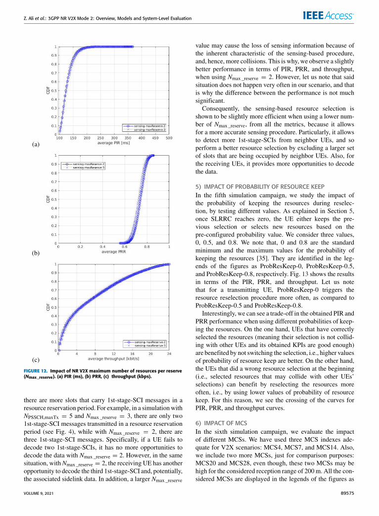
Z. Ali et al.: 3GPP NR V2X Mode 2: Overview, Models and System-Level Evaluation
FIGURE 12. Impact of NR V2X maximum number of resources per reserve(Nmax _reserve). (a) PIR (ms), (b) PRR, (c) throughput (kbps).
there are more slots that carry 1st-stage-SCI messages in aresource reservation period. For example, in a simulationwithNPSSCH,maxTx = 5 and Nmax _reserve = 3, there are only two1st-stage-SCI messages transmitted in a resource reservationperiod (see Fig. 4), while with Nmax _reserve = 2, there arethree 1st-stage-SCI messages. Specifically, if a UE fails todecode two 1st-stage-SCIs, it has no more opportunities todecode the data with Nmax _reserve = 2. However, in the samesituation, withNmax _reserve = 2, the receiving UE has anotheropportunity to decode the third 1st-stage-SCI and, potentially,the associated sidelink data. In addition, a larger Nmax _reserve
value may cause the loss of sensing information because ofthe inherent characteristic of the sensing-based procedure,and, hence, more collisions. This is why, we observe a slightlybetter performance in terms of PIR, PRR, and throughput,when using Nmax _reserve = 2. However, let us note that saidsituation does not happen very often in our scenario, and thatis why the difference between the performance is not muchsignificant.
Consequently, the sensing-based resource selection isshown to be slightly more efficient when using a lower num-ber of Nmax _reserve, from all the metrics, because it allowsfor a more accurate sensing procedure. Particularly, it allowsto detect more 1st-stage-SCIs from neighbor UEs, and soperform a better resource selection by excluding a larger setof slots that are being occupied by neighbor UEs. Also, forthe receiving UEs, it provides more opportunities to decodethe data.
5) IMPACT OF PROBABILITY OF RESOURCE KEEPIn the fifth simulation campaign, we study the impact ofthe probability of keeping the resources during reselec-tion, by testing different values. As explained in Section 5,once SLRRC reaches zero, the UE either keeps the pre-vious selection or selects new resources based on thepre-configured probability value. We consider three values,0, 0.5, and 0.8. We note that, 0 and 0.8 are the standardminimum and the maximum values for the probability ofkeeping the resources [35]. They are identified in the leg-ends of the figures as ProbResKeep-0, ProbResKeep-0.5,and ProbResKeep-0.8, respectively. Fig. 13 shows the resultsin terms of the PIR, PRR, and throughput. Let us notethat for a transmitting UE, ProbResKeep-0 triggers theresource reselection procedure more often, as compared toProbResKeep-0.5 and ProbResKeep-0.8.
Interestingly, we can see a trade-off in the obtained PIR andPRR performance when using different probabilities of keep-ing the resources. On the one hand, UEs that have correctlyselected the resources (meaning their selection is not collid-ing with other UEs and its obtained KPIs are good enough)are benefited by not switching the selection, i.e., higher valuesof probability of resource keep are better. On the other hand,the UEs that did a wrong resource selection at the beginning(i.e., selected resources that may collide with other UEs’selections) can benefit by reselecting the resources moreoften, i.e., by using lower values of probability of resourcekeep. For this reason, we see the crossing of the curves forPIR, PRR, and throughput curves.
6) IMPACT OF MCSIn the sixth simulation campaign, we evaluate the impactof different MCSs. We have used three MCS indexes ade-quate for V2X scenarios: MCS4, MCS7, and MCS14. Also,we include two more MCSs, just for comparison purposes:MCS20 and MCS28, even though, these two MCSs may behigh for the considered reception range of 200 m. All the con-sidered MCSs are displayed in the legends of the figures as
VOLUME 9, 2021 89575
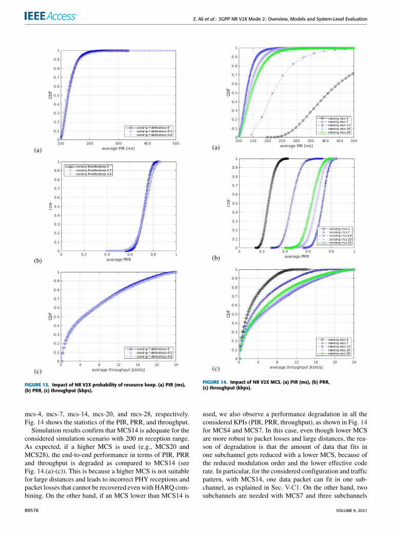
Z. Ali et al.: 3GPP NR V2X Mode 2: Overview, Models and System-Level Evaluation
FIGURE 13. Impact of NR V2X probability of resource keep. (a) PIR (ms),(b) PRR, (c) throughput (kbps).
mcs-4, mcs-7, mcs-14, mcs-20, and mcs-28, respectively.Fig. 14 shows the statistics of the PIR, PRR, and throughput.
Simulation results confirm that MCS14 is adequate for theconsidered simulation scenario with 200 m reception range.As expected, if a higher MCS is used (e.g., MCS20 andMCS28), the end-to-end performance in terms of PIR, PRRand throughput is degraded as compared to MCS14 (seeFig. 14.(a)-(c)). This is because a higher MCS is not suitablefor large distances and leads to incorrect PHY receptions andpacket losses that cannot be recovered even with HARQ com-bining. On the other hand, if an MCS lower than MCS14 is
FIGURE 14. Impact of NR V2X MCS. (a) PIR (ms), (b) PRR,(c) throughput (kbps).
used, we also observe a performance degradation in all theconsidered KPIs (PIR, PRR, throughput), as shown in Fig. 14for MCS4 and MCS7. In this case, even though lower MCSare more robust to packet losses and large distances, the rea-son of degradation is that the amount of data that fits inone subchannel gets reduced with a lower MCS, because ofthe reduced modulation order and the lower effective coderate. In particular, for the considered configuration and trafficpattern, with MCS14, one data packet can fit in one sub-channel, as explained in Sec. V-C1. On the other hand, twosubchannels are needed with MCS7 and three subchannels
89576 VOLUME 9, 2021
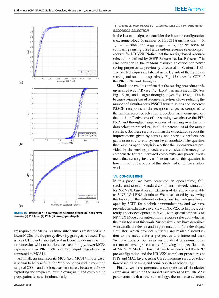
Z. Ali et al.: 3GPP NR V2X Mode 2: Overview, Models and System-Level Evaluation
FIGURE 15. Impact of NR V2X resource selection procedure: sensing vsrandom. (a) PIR (ms), (b) PRR, (c) throughput (kbps).
are required for MCS4. As more subchannels are needed withlower MCSs, the frequency diversity gain gets reduced. Thatis, less UEs can be multiplexed in frequency domain withinthe same slot, without interference. Accordingly, lowerMCSsexperience also PIR, PRR and throughput degradation ascompared to MCS14.
All in all, an intermediate MCS (i.e., MCS14 in our case)is shown to be beneficial for V2X scenarios with a receptionrange of 200 m and the broadcast use cases, because it allowsexploiting the frequency multiplexing gain and overcomingpropagation losses, simultaneously.
D. SIMULATION RESULTS: SENSING-BASED VS RANDOMRESOURCE SELECTIONIn the last campaign, we consider the baseline configuration(i.e., numerology 0, number of PSSCH transmissions = 5,T2 = 32 slots, and Nmax _reserve = 3) and we focus oncomparing sensing-based and random resource selection pro-cedures for NR V2X. Notice that the sensing-based resourceselection is defined by 3GPP Release 16, but Release 17 isalso considering the random resource selection for powersaving purposes, as previously discussed in Section III-B1.The two techniques are labeled in the legends of the figures assensing and random, respectively. Fig. 15 shows the CDF ofthe PIR, PRR, and throughput.
Simulation results confirm that the sensing procedure endsup in a reduced PIR (see Fig. 15.(a)), an increased PRR (seeFig. 15.(b)), and a larger throughput (see Fig. 15.(c)). This isbecause sensing-based resource selection allows reducing thenumber of simultaneous PSSCH transmissions and incorrectPSSCH receptions in the reception range, as compared tothe random resource selection procedure. As a consequence,due to the effectiveness of the sensing, we observe the PIR,PRR, and throughput improvement of sensing over the ran-dom selection procedure, in all the percentiles of the outputstatistics. So, these results confirm the expectations about theimprovements given by sensing and show its performancegains in an end-to-end system-level simulator. The questionthat remains open though is whether the improvements pro-vided by the sensing procedure are considerable enough tocompensate for the increased complexity and power invest-ment that sensing involves. The answer to this question ishowever out of the scope of this study and is left for a futurework.
VI. CONCLUSIONSIn this paper, we have presented an open-source, full-stack, end-to-end, standard-compliant network simulatorfor NR V2X, based on an extension of the already availablens-3 NR 5G-LENA simulator. We have started by reviewingthe history of the different radio access technologies devel-oped by 3GPP for sidelink communications and we haveprovided an exhaustive overview of NRV2X technology, cur-rently under development in 3GPP, with special emphasis onNRV2XMode 2 for autonomous resource selection, which isthe main focus of this work. Successively, we have describedwith details the design and implementation of the developedsimulator, which provides a useful and readable introduc-tion to the module for a prospective and interested user.We have focused our work on broadcast communicationsfor out-of-coverage scenarios, following the specificationsof NR V2X Mode 2. For that, we have described the RRCpre-configuration and the NR V2X-compliant procedures atPHY and MAC layers, using UE autonomous resource selec-tion based on sensing and semi-persistent scheduling.
Finally, we have presented a complete set of simulationcampaigns, including the impact assessment of key NR V2Xparameters, such as the numerology, the resource selection
VOLUME 9, 2021 89577
Z. Ali et al.: 3GPP NR V2X Mode 2: Overview, Models and System-Level Evaluation
window, the number of retransmissions, the maximum num-ber of resources per reservation, the probability of resourcekeep, and the MCS, as well as a comparison of sensing andrandom based resource selection procedures. The seven sim-ulation campaigns that we have conducted have highlightedthe following:
1) Onlyµ = 2 exhibits clear benefit to improve PIR, PRR,and throughput performance metrics.
2) A low number of blind retransmissions is alreadyoptimal in scenarios with good propagation condi-tions, because of the effectiveness of the sensing-basedresource selection.
3) A trade-off is exhibited in terms of resource selectionwindow length.
4) The maximum number of resources per reservationdoes not has an appreciable impact on the end-to-endperformance.
5) A trade-off is observed in terms of the probability ofresource keep for NR V2X with periodic traffic.
6) An intermediate MCS is shown to be optimal for V2Xscenarios and broadcast use cases.
7) Appreciable but not significant gains are obtained byusing sensing-based resource selection, in comparisonto the random resource selection strategy, which isconsidered in 3GPP Release 17.
With these campaigns we have only touched the tip of theiceberg and many more studies can be conducted by theresearch community, considering the proposed open-sourceplatform as a basis for analysis.
This work is only the first step to provide full support forend-to-end simulations of NR V2X networks, through an up-to-date and standard-compliant platform. Interesting futureevaluations include higher transmitter densities, different sce-narios, and different traffic models. In the near future weplan to extend the work to account for additional featuresand functionalities envisioned for NR V2X in Release 17 andonwards. Future works will include the feedback channel forHARQ-ACK and CSI reports, feedback-based retransmis-sions, new schedulers’ implementation, beam managementprocedures, and support for unicast communications. As thecode is openly released, we hope that the developed simulatorwill contribute to research advancement in the areas of vehic-ular communications, public safety scenarios, and Beyond5G, among others.
REFERENCES[1] U. S. Department of Transportation. (Jul. 2017). Vehicle-to-Vehicle
Communication Technology. [Online]. Available: https://www.nhtsa.gov/sites/nhtsa.dot.gov/files/documents/v2v_fact_sheet_101414_v2a.pdf
[2] Study Enhancement 3GPP Support for 5G V2X Services (Release 16),v16.2.0, document 3GPP TR 22.886, Dec. 2018.
[3] 5G Automotive Association, ‘‘5G automotive vision,’’ 5G-PPPAutomot. Vertical Sector, White Paper, Oct. 2015. [Online].Available: https://5g-ppp.eu/white-papers/ and https://5g-ppp.eu/wp-content/uploads/2014/02/5G-PPP-White-Paper-on-Automotive-Vertical-Sectors.pdf
[4] D. Jiang and L. Delgrossi, ‘‘IEEE 802.11p: Towards an internationalstandard for wireless access in vehicular environments,’’ in Proc. IEEEVeh. Technol. Conf. (VTC Spring), May 2008, pp. 2036–2040.
[5] G. Naik, B. Choudhury, and J.-M. Park, ‘‘IEEE 802.11bd & 5G NR V2X:Evolution of radio access technologies for V2X communications,’’ IEEEAccess, vol. 7, pp. 70169–70184, 2019.
[6] R. Molina-Masegosa and J. Gozalvez, ‘‘LTE-V for sidelink 5G V2Xvehicular communications: A new 5G technology for short-range vehicle-to-everything communications,’’ IEEE Veh. Technol. Mag., vol. 12, no. 4,pp. 30–39, Dec. 2017.
[7] Service Requirements for V2X Services (Release 14), v16.0.0, document3GPP TS 22.185, Jun. 2020.
[8] An Assessment LTE-V2X (PC5) and 802.11pDirect Communications Tech-nologies for Improved Road Safety in the EU, 5GAA, Munich, Germany,Dec. 2017.
[9] Study on NR Vehicular to Everything (V2X) (Release 16), v16.0.0,document 3GPP TR 38.885, Mar. 2019.
[10] 5G V2X With NR Sidelink (Release 16), Work Item description, document3GPP RP-190766, Dec. 2018.
[11] S. Parkvall, E. Dahlman, A. Furuskar, and M. Frenne, ‘‘NR: The new 5Gradio access technology,’’ IEEE Commun. Standards Mag., vol. 1, no. 4,pp. 24–30, Dec. 2017.
[12] M. Gonzalez-Martin, M. Sepulcre, R. Molina-Masegosa, and J. Gozalvez,‘‘Analytical models of the performance of C-V2X mode 4 vehicular com-munications,’’ IEEE Trans. Veh. Technol., vol. 68, no. 2, pp. 1155–1166,Feb. 2019.
[13] R. Molina-Masegosa, J. Gozalvez, and M. Sepulcre, ‘‘Comparison ofIEEE 802.11p and LTE-V2X: An evaluation with periodic and ape-riodic messages of constant and variable size,’’ IEEE Access, vol. 8,pp. 121526–121548, 2020.
[14] B. Toghi, M. Saifuddin, H. N. Mahjoub, M. O. Mughal, Y. P. Fallah,J. Rao, and S. Das, ‘‘Multiple access in cellular V2X: Performance analysisin highly congested vehicular networks,’’ in Proc. IEEE Veh. Netw. Conf.(VNC), Dec. 2018, pp. 1–8.
[15] T. Zugno, M. Drago, M. Giordani, M. Polese, and M. Zorzi, ‘‘Toward stan-dardization of millimeter-wave vehicle-to-vehicle networks: Open chal-lenges and performance evaluation,’’ IEEE Commun. Mag., vol. 58, no. 9,pp. 79–85, Sep. 2020.
[16] K. Ganesan, J. Lohr, P. B. Mallick, A. Kunz, and R. Kuchibhotla, ‘‘NRsidelink design overview for advancedV2X service,’’ IEEE Internet ThingsMag., vol. 3, no. 1, pp. 26–30, Mar. 2020.
[17] S.-Y. Lien, D.-J. Deng, C.-C. Lin, H.-L. Tsai, T. Chen, C. Guo, andS.-M. Cheng, ‘‘3GPP NR sidelink transmissions toward 5G V2X,’’ IEEEAccess, vol. 8, pp. 35368–35382, 2020.
[18] M. H. C. Garcia, A.Molina-Galan,M. Boban, J. Gozalvez, B. Coll-Perales,T. Sahin, and A. Kousaridas, ‘‘A tutorial on 5G NR V2X communica-tions,’’ IEEE Commun. Surveys Tuts., early access, Feb. 3, 2021, doi:10.1109/COMST.2021.3057017.
[19] C. Campolo, A. Molinaro, F. Romeo, A. Bazzi, and A. O. Berthet, ‘‘5GNR V2X: On the impact of a flexible numerology on the autonomoussidelink mode,’’ in Proc. IEEE 2nd 5G World Forum (5GWF), Sep. 2019,pp. 102–107.
[20] R. Rouil, F. J. Cintrón, A. Ben Mosbah, and S. Gamboa, ‘‘Implementationand validation of an LTE D2D model for NS-3,’’ in Proc. Workshop NS-3(WNS3), 2017, pp. 55–62.
[21] F. Eckermann, M. Kahlert, and C. Wietfeld, ‘‘Performance analysis of C-V2X mode 4 communication introducing an open-source C-V2X simu-lator,’’ in Proc. IEEE 90th Veh. Technol. Conf. (VTC-Fall), Sep. 2019,pp. 1–5.
[22] M. Malinverno, F. Raviglione, C. Casetti, C.-F. Chiasserini,J. Mangues-Bafalluy, and M. Requena-Esteso, ‘‘A multi-stack simulationframework for vehicular applications testing,’’ in Proc. 10th ACM Symp.Design Anal. Intell. Veh. Netw. Appl., New York, NY, USA, Nov. 2020,pp. 17–24.
[23] G. Cecchini, A. Bazzi, B. M. Masini, and A. Zanella, ‘‘LTEV2 VSIM:An LTE-V2 V simulator for the investigation of resource allocation forcooperative awareness,’’ in Proc. 5th IEEE Int. Conf. Models Technol.Intell. Transp. Syst. (MT-ITS), Jun. 2017, pp. 80–85.
[24] M. Drago, T. Zugno, M. Polese, M. Giordani, and M. Zorzi, ‘‘MilliCar: AnNS-3 module for mmWave NR V2X networks,’’ in Proc. Workshop NS-3,Jun. 2020, pp. 9–16.
[25] N. Patriciello, S. Lagen, B. Bojovic, and L. Giupponi, ‘‘An E2E simulatorfor 5G NR networks,’’ Simul. Model. Pract. Theory, vol. 96, Nov. 2019,Art. no. 101933.
[26] CTTC. 5G LENA Project. Accessed: May 31, 2021. [Online]. Available:https://5g-lena.cttc.es/download/
89578 VOLUME 9, 2021
Z. Ali et al.: 3GPP NR V2X Mode 2: Overview, Models and System-Level Evaluation
[27] Proximity-Based Services (ProSe), Stage 2, v20.0.0, document 3GPP TS23.303, Jun. 2020.
[28] Study LTE Device to Device Proximity Services; Radio Aspects (Rel. 12),v12.0.1, document 3GPP TR 38.843, Mar. 2014.
[29] User Equipment (UE) Radio Transmission and Reception; Part 1: Range1 Standalone, Rel. 17, document 3GPP TS 38.101, Mar. 2021.
[30] V2X Services Based on NR; User Equipment (UE) Radio Transmission andReception, document 3GPP TR 38.886, Mar. 2021.
[31] TSG RAN; NR; Physical layer; General Description, Release 15, v16.0.0,document 3GPP TS 38.201, Jan. 2020.
[32] TSG RAN; NR; Physical Channels and Modulation, Release 15, v16.4.0,document 3GPP TS 38.211, Jan. 2021.
[33] TSG RAN; NR; Physical Layer Procedures for Data, Release 15, v16.4.0,document 3GPP TS 38.214, Jan. 2021.
[34] TSG RAN; NR; Services Provided by the Physical Layer, Release 15,v16.2.0, document 3GPP TS 38.202, Sep. 2020.
[35] TSG RAN; NR; Radio Resource Control (RRC); Protocol Specification,Release 15, v16.2.0, document 3GPP TS 38.331, Sep. 2020.
[36] Radio Resource Control (RRC); Protocol specification, Rel. 16, document3GPP TS 36.331, Jul. 2020.
[37] Final Report of 3GPP TSG RAN WG1 #100bis-e v1.0.0, document 3GPPTSG RAN WG1 Meeting #101-e, Apr. 2020.
[38] M. H. C. Garcia, A.Molina-Galan,M. Boban, J. Gozalvez, B. Coll-Perales,T. Sahin, and A. Kousaridas, ‘‘A tutorial on 5G NR V2X communica-tions,’’ IEEE Commun. Surveys Tuts., early access, Feb. 3, 2021, doi:10.1109/COMST.2021.3057017.
[39] TSG RAN; NR; Medium Access Control (MAC) Protocol Specification,Release 15, v16.3.0, document 3GPP TS 38.321, Jan. 2021.
[40] New WID NR Sidelink Enhancement, document RP-193231, 3GPP TSGRAN 86 Meeting, Dec. 2019.
[41] TSG RAN; NR; Multiplexing Channel Coding, Release 15, v16.4.0,document 3GPP TS 38.212, Jan. 2021.
[42] TSG RAN; NR; Physical Layer Procedures for Control, Release 15,v16.4.0, document 3GPP TS 38.213, Jan. 2021.
[43] TSG RAN; NR; Physical Layer Measurements, Release 15, v16.4.0,document 3GPP TS 38.215, Jan. 2021.
[44] TSG RAN; NR; Overall description; Stage 2, Release 15, v16.3.0,document 3GPP TS 38.300, Sep. 2020.
[45] S. Lagen, K.Wanuga, H. Elkotby, S. Goyal, N. Patriciello, and L. Giupponi,‘‘New radio physical layer abstraction for system-level simulations of 5Gnetworks,’’ in Proc. IEEE Int. Conf. Commun. (ICC), Jun. 2020, pp. 1–7.
[46] Study on New Radio (NR) Access Technology; Physical Layer Aspects(Release 14), v14.2.0, document 3GPP TR 38.802, Sep. 2017.
[47] Study on EvaluationMethodology of NewVehicle-to-Everything (V2X) UseCases for LTE and NR (Rel. 15), V15.3.0, document 3GPP TR 37.885,Jun. 2019.
[48] TSG RAN; NR; Radio Link Control (RLC) Protocol 1686 Specification,Release 16, v16.2.0, document 3GPP TS 38.322, Jan. 2021.
[49] Study on Channel Model for Frequencies From 0.5 to 100 GHz (Rel. 15),V15.0.0, document 3GPP TR 38.901, Jun. 2019.
[50] A. Bazzi, G. Cecchini, A. Zanella, and B. M. Masini, ‘‘Study of the impactof PHY and MAC parameters in 3GPP C-V2 V mode 4,’’ IEEE Access,vol. 6, pp. 71685–71698, 2018.
ZORAZE ALI received the M.Sc. degree in radiocommunication from the Blekinge Institute ofTechnology, Karlskrona, Sweden. He is currentlypursuing the Ph.D. degree in self organizing net-works (SON), big data, and machine learning withthe Telematics Engineering Department of Univer-sitat Politècnica de Catalunya (UPC), Barcelona,with a focus on LTE/LTE-A and 5G networks.He joined as a Research Assistant with the CentreTecnològic de Telecomunicacions de Catalunya
(CTTC), in September 2014. His research interests include wireless com-munications and machine learning.
SANDRA LAGÉN (Senior Member, IEEE)received the bachelor’s degree in telecommu-nications engineering and the M.Sc. and Ph.D.degrees from UPC, Spain, in 2011, 2013, and2016, respectively. From 2012 to 2016, she wasa Research Assistant with the Signal Processingand Communications Group, UPC. In 2015, shedid a research appointment at Nokia Networks,Aalborg, Denmark. Since 2017, she has been aResearcher with the Mobile Networks Depart-
ment, CTTC, Castelldefels, Spain. Her research interests include wirelesscommunications, spectrum and interference management, and optimizationtheory. Her dissertation was awarded by COIT the Best National Ph.D.Thesis on high-speed broadband mobile communications, in 2017, and theSpecial Doctoral Award by UPC, in 2019. She was a recipient of the IEEEWCNC 2018 and the WNS3 2020 Best Paper Award.
LORENZA GIUPPONI received the Ph.D. degreefromUPC, Barcelona, Spain, in 2007. In 2003, shejoined the Radio Communications Group, UPC,with a grant of the Spanish Ministry of Education.From 2006 to 2007, she was an Assistant Profes-sor with UPC. In September 2007, she joined theCTTC, where she is currently a Research Directorwith the Mobile Networks Department, Commu-nication Networks Division. Since 2007, she hasbeen a member of the Executive Committee of
CTTC, where she acts as the Director of Institutional Relations. She was aco-recipient of the IEEE CCNC 2010, the IEEE 3rd International Workshopon Indoor and Outdoor Femto Cells 2011, and the IEEE WCNC 2018 BestPaper Award. Since 2015, she has been a member of the Executive Commit-tee of ns-3 Consortium.
RICHARD ROUIL received the Ph.D. degree incomputer science from Telecom Bretagne, France,in 2009, with a focuses on mobility in heteroge-neous networks. He is currently a Researcher withthe Wireless Networks Division, National Insti-tute of Standards and Technology (NIST). He isalso leading a team of researchers that focuses onthe performance evaluation of wireless technolo-gies, such as long term evolution (LTE) and newradio (NR) to support the deployment of networks
used by public safety practitioners. His main interests include protocolmodeling and simulation of communication networks.
VOLUME 9, 2021 89579
![3GPP 5G NR System Design & Verification SolutionA6...3GPP 5G NR System Design & Verification Solution 2 arXiv:1704.02540v1 [csIT] 8 Apr 2017 [ Block diagram of 5G use equipment wireless](https://static.fdocuments.us/doc/165x107/61047f06ecbc7d614d7bccc6/3gpp-5g-nr-system-design-verification-solution-a6-3gpp-5g-nr-system-design.jpg)