
3,000 LB 12 VOLT WINCH WITH ROLLER FAIRLEAD · PDF file30 seconds otherwise motor damage may...
10
*Actual product may vary slightly Please carefully read and save these instructions before attempting to assemble, maintain, install, or operate this product. Observe all safety information to protect yourself and others. Failure to observe the instructions may result in property damage and/or personal injury. Please keep instructions for future reference. For warranty purchases, please keep your dated proof of purchase. File or attach to the manual for safe keeping. For Customer Service, Call 1-800-348-5004 or e-mail [email protected] 07253 08/2016 This product contains or, when used, produces a chemical known to the State of California to cause cancer and birth defects or other reproductive harm. (California Health & Safety Code § 25249.5, et seq.) WARNING 3,000 LB 12 VOLT WINCH WITH ROLLER FAIRLEAD
Transcript of 3,000 LB 12 VOLT WINCH WITH ROLLER FAIRLEAD · PDF file30 seconds otherwise motor damage may...
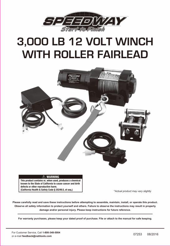
*Actual product may vary slightly
Please carefully read and save these instructions before attempting to assemble, maintain, install, or operate this product.Observe all safety information to protect yourself and others. Failure to observe the instructions may result in property
damage and/or personal injury. Please keep instructions for future reference.
For warranty purchases, please keep your dated proof of purchase. File or attach to the manual for safe keeping.
For Customer Service, Call 1-800-348-5004or e-mail [email protected] 07253 08/2016
This product contains or, when used, produces a chemicalknown to the State of California to cause cancer and birthdefects or other reproductive harm.(California Health & Safety Code § 25249.5, et seq.)
WARNING
3,000 LB 12 VOLT WINCHWITH ROLLER FAIRLEAD
WARNING: FAILURE TO READ AND FOLLOW THE SAFETY INSTRUCTIONS IN THISOWNER’S MANUAL BEFORE INSTALLING OR USING YOUR ELECTRIC WINCHCOULD RESULT IN DAMAGE TO YOUR WINCH AND SERIOUS OR FATAL INJURY!!
GENERAL SAFETY PRECAUTIONS
[email protected] 2 1-800-348-5004
Check all safety and environmental conditions prior and during use.
The winches duty rating is S3 (intermittent – periodic)
Ensure that the winch is connected to the correct voltage of 12VDC only.Check that the freespool shifter is in the “Engaged” position during and after use.Remove the remote control from the winch when not in use.
Keep hands and clothes away from the winch, wire rope, and fairlead during operation.Never unplug the remote control and battery leads when winching a load.
Before use, ensure that you are familiar with all winching performance and operationsuch as speed & direction.A wire rope should be replaced if it shows signs of excessive wear, broken wires,corrosion or any other defects.
The winch is rated for intermittent-periodic duty.
Never operate the winch under water.
The winch is not to be used to lift, support or otherwise transport personnel.A minimum of five (5) wraps of rope around the drum are necessary to support therated load.
Operate the winch cable in and cable out at no load after a winch was ingressedby water.
The rated line pull of the winch must be powerful enough to overcome the addedresistance caused by whatever the vehicle is stuck in.
If the winch fails to pull a load under normal conditions, stop the operation within30 seconds otherwise motor damage may occur.
Do not wrap the wire rope around the load and back onto it self. Always use a strapto ensure that the wire rope does not fray or kink.
To avoid insufficient power when winching a load, the vehicle should be running andin neutral.When winching a heavy load, lay a heavy blanket or jacket over the wire rope near tothe hook endIf excessive noise or vibration occurs when running, stop the winch immediately andreturn it for repair.
WARNING
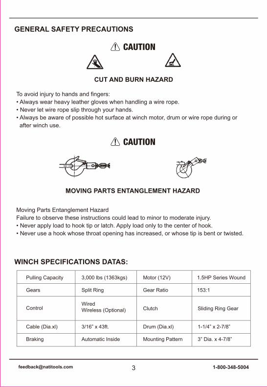
To avoid injury to hands and fingers: • Always wear heavy leather gloves when handling a wire rope. • Never let wire rope slip through your hands. • Always be aware of possible hot surface at winch motor, drum or wire rope during or after winch use.
Moving Parts Entanglement Hazard Failure to observe these instructions could lead to minor to moderate injury.• Never apply load to hook tip or latch. Apply load only to the center of hook. • Never use a hook whose throat opening has increased, or whose tip is bent or twisted.
CUT AND BURN HAZARD
MOVING PARTS ENTANGLEMENT HAZARD
GENERAL SAFETY PRECAUTIONS
[email protected] 3 1-800-348-5004
CAUTION
CAUTION
WINCH SPECIFICATIONS DATAS:
Pulling Capacity
Gears
Cable (Dia.xl)
Braking
Control
3,000 lbs (1363kgs)
Split Ring
3/16” x 43ft.
Automatic Inside
WiredWireless (Optional)
Motor (12V)
Gear Ratio
Drum (Dia.xl)
Mounting Pattern
Clutch
1.5HP Series Wound
153:1
1-1/4” x 2-7/8”
3” Dia. x 4-7/8”
Sliding Ring Gear

1. It is very important that the winch shall be mounted on a flat hard surface in order to make sure the motor, drum and gearbox housing are aligned correctly.2. If a different mounting plate is used, the thickness shall be 5 mm (3/16”). If different hardware is used, it must be grade 8 minimum.3. Four (4) included M8x 25L Grade 8.8 High Tensile Steel Bolts must be used for securing the winch on the mounting plate in order to sustain the loads imposed on the winch mounting.4. Two (2) included M8 x 20L Grade 8.8 High Tensile Steel Bolts must be used for securing the roller fairlead on the mounting plate.
WINCH & ROLLER FAIRLEAD MOUNTING
Long Red cable to Battery(+) PositiveLong Black cable to Battery(-) NegativeShort Red cable to Motor(+) PositiveShort Blace cable to Motor(-) Negative
[email protected] 4 1-800-348-5004
WIRE CONNECTION

HANDLEBAR REMOTE CONTROL MOUNTING
OPERATION
CABLE IN AND OUT
Handlebar mounted trigger switch can be operated without removing your hand from the grip.
• It is recommended that the switch be installed on the left handlebar. A piece of electrical tape around the handlebar will help prevent rotation of mount on the handle bar.
• Do NOT tighten over any hoses or cables.
1). To determine “ Cable Out “, turn to the “Out” position2). To determine “ Cable In “, turn to the “In” position3). To stop winching, release the trigger level
[email protected] 5 1-800-348-5004
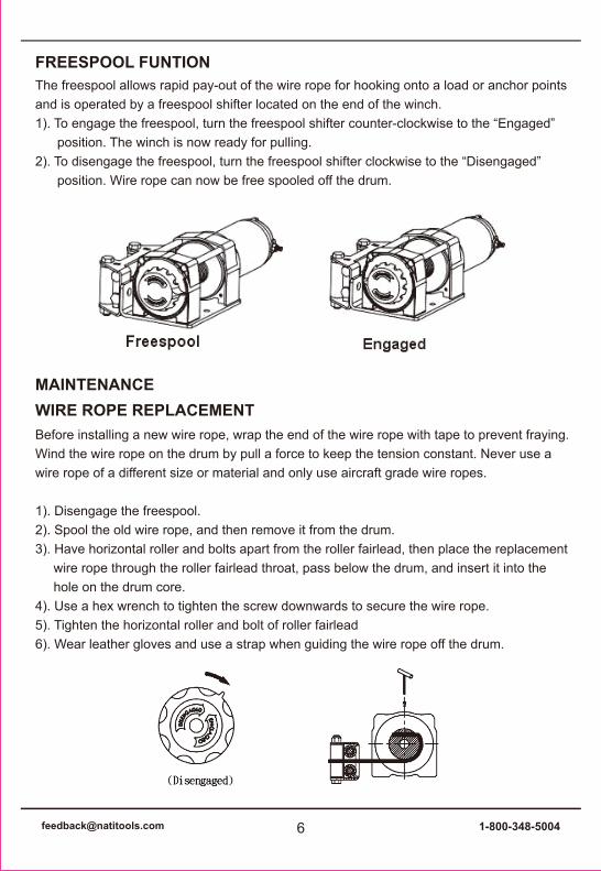
The freespool allows rapid pay-out of the wire rope for hooking onto a load or anchor pointsand is operated by a freespool shifter located on the end of the winch.1). To engage the freespool, turn the freespool shifter counter-clockwise to the “Engaged” position. The winch is now ready for pulling.2). To disengage the freespool, turn the freespool shifter clockwise to the “Disengaged” position. Wire rope can now be free spooled off the drum.
Before installing a new wire rope, wrap the end of the wire rope with tape to prevent fraying.Wind the wire rope on the drum by pull a force to keep the tension constant. Never use awire rope of a different size or material and only use aircraft grade wire ropes.
1). Disengage the freespool.2). Spool the old wire rope, and then remove it from the drum.3). Have horizontal roller and bolts apart from the roller fairlead, then place the replacement wire rope through the roller fairlead throat, pass below the drum, and insert it into the hole on the drum core.4). Use a hex wrench to tighten the screw downwards to secure the wire rope.5). Tighten the horizontal roller and bolt of roller fairlead6). Wear leather gloves and use a strap when guiding the wire rope off the drum.
FREESPOOL FUNTION
MAINTENANCEWIRE ROPE REPLACEMENT
[email protected] 6 1-800-348-5004
LUBRICATIONAll moving parts in the winch are permanently lubricated at the time of assembly. Undernormal conditions factory lubrication will suffice. If re-lubrication is necessary after repairor disassembly use a marine type grease.
7). It is very important that the winch shall be mounted on a flat surface, with the wire rope feeding form the bottom of the drum.8). To rewind wire rope on the drum correctly , it is necessary to keep a slight load on the wire rope while cable in.
CHECK THE SYSTEMBefore using the winch, verify the following:1) Wiring to all components is correct. All loose wires are tie wrapped tight.2) There are no exposed wiring or terminals. Cover any existing terminal exposures withterminal boots, heat shrink tubing or electricians tape.3) Turn ATV key switch to ON position. Check winch for proper operation. The wire ropeshould spool in and out in the direction indicated on the switch.
KNOW YOUR WINCH
• Take time to fully understand your winch and the winching operation by reviewing the manual with your winch.
[email protected] 7 1-800-348-5004
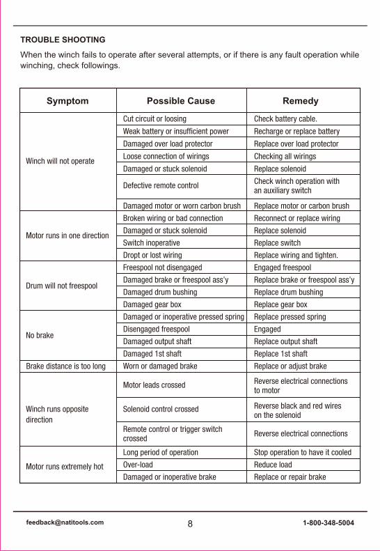
When the winch fails to operate after several attempts, or if there is any fault operation whilewinching, check followings.
TROUBLE SHOOTING
[email protected] 8 1-800-348-5004
Winch will not operate
Cut circuit or loosing
Weak battery or insufficient power
Damaged over load protector
Loose connection of wirings
Damaged or stuck solenoid
Defective remote control
Damaged motor or worn carbon brush
Broken wiring or bad connection
Damaged or stuck solenoid
Switch inoperative
Dropt or lost wiring
Freespool not disengaged
Damaged brake or freespool ass’y
Damaged drum bushing
Damaged gear box
Damaged or inoperative pressed spring
Disengaged freespool
Damaged output shaft
Damaged 1st shaft
Worn or damaged brake
Check battery cable.
Recharge or replace battery
Replace over load protector
Checking all wirings
Replace solenoid
Check winch operation withan auxiliary switch
Replace motor or carbon brush
Reconnect or replace wiring
Replace solenoid
Replace switch
Replace wiring and tighten.
Engaged freespool
Replace brake or freespool ass’y
Replace drum bushing
Replace gear box
Replace pressed spring
Engaged
Replace output shaft
Replace 1st shaft
Replace or adjust brake
Motor leads crossed
Solenoid control crossed
Remote control or trigger switchcrossed
Long period of operation
Over-load
Damaged or inoperative brake
Reverse electrical connectionsto motor
Reverse black and red wireson the solenoid
Reverse electrical connections
Stop operation to have it cooled
Reduce load
Replace or repair brake
Symptom RemedyPossible Cause
Motor runs in one direction
Drum will not freespool
No brake
Brake distance is too long
Winch runs oppositedirection
Motor runs extremely hot

PARTS LIST & ASSEMBLY DIAGRAM
[email protected] 9 1-800-348-5004
Part Description Quantity Part Description Quantity 1 Motor Cover 1 13 Drum 1 2 Motor Shell 1 14 Plastic Plate 1 3 Rotor 1 15 Triangle Plate 1 4 Bear ing 1 16 Base 1 5 Motor Base 1 17 Clutch 1 6 Planetary Gear 1 18 Steel Cable 1 7 Static Ring Gear 1 19 Mounting Plate 1 8 Plastic Plate 1 20 Roller Fairlead 1 9 Tie Rod 2 21 Hook 1
10 Shaft 1 22 Strap 1 11 Spine 1 23 Handlebar Remote 1 12 Spring 1 24 Control box 1
Limited Manufacturer WarrantyNorth American Tool Industries (NATI) makes every effort to ensure that this productmeets high quality and durability standards. NATI warrants to the original retail consumera 1-year limited warranty from the date the product was purchased at retail and eachproduct is free from defects in materials. Warranty does not apply to defects due directlyor indirectly to misuse, abuse, negligence or accidents, repairs or alterations, or a lack ofmaintenance. This product is intended for personal use. The warranty will be voided ifused in commercial, rental, or industrial applications. NATI shall in no event be liable fordeath, injuries to persons or property, or for incidental, special or consequential damagesarising from the use of our products. To receive service under warranty, the originalmanufacturer part must be returned for examination by an authorized service center.Shipping and handling charges may apply. If a defect is found, NATI will either repair orreplace the product at its discretion.
DO NOT RETURN TO STOREFor Customer Service:Email: [email protected] or Call 1-800-348-5004
[email protected] 10 1-800-348-5004