3-Axis LASER MARKER - Keyenceresources.keyence.com/rs/ipros/images/mdm-w_marker.pdf · KEYENCE is a...
28
3-Axis LASER MARKER G E N E R A L C A T A L O G
Transcript of 3-Axis LASER MARKER - Keyenceresources.keyence.com/rs/ipros/images/mdm-w_marker.pdf · KEYENCE is a...

3-Axis LASER MARKERG E N E R A L C A T A L O G

2
Who We AreKEYENCE has steadily grown since 1974 to become an innovative leader in the
development and manufacturing of automation equipment worldwide. Our products
consist of automation sensors, measuring instruments, vision systems, laser markers,
and digital microscopes.
Our innovative products not only meet current needs but also future customer
requirements in many manufacturing and research industries. We strive to anticipate the
market’s future needs to provide tomorrow’s solution today.
At KEYENCE, we are not content to only have the best products on the market, we
also strive to provide our customers with the most knowledgeable and trained sales
professionals in the industry. We are dedicated to supporting our customers and
working with them to achieve their goals.
KEYENCE, a blue chip company, has been named one of Business Week’s “1000
Best Valued Companies”. We are also in the top 50 of Newsweek’s electronic industry
ranking and are consistently ranked in Japan’s Nikkei Newspaper’s yearly list of the
“Top Ten Excellent Companies in Japan”. Today, KEYENCE serves over 100,000
customers in some 70 countries around the world, where its name stands for innovation
and excellence.
Direct ApproachKEYENCE employs a large number of sales engineers throughout the world enabling
invaluable direct on-site support. With this direct approach, we are able to meet the
customer’s needs at every level of their business, from the design and research stage
to the production line and beyond.
These highly trained sales engineers are problem solvers who can provide real solutions
to our customers’ applications with existing products or potential new solutions.
Superior TechnologyKEYENCE is a worldwide leader in developing and supplying cutting-edge automation
and manufacturing technologies of the highest quality. New product sales consistently
account for 30% of KEYENCE’s total sales, illustrating our ability to quickly respond to
industry trends and add value to our customers.
Versatile ProductsKEYENCE manufactures a broad range of products used in both manufacturing
environments and research facilities. These products are designed with versatility in
mind and can be used across all industry sectors. We know quick delivery is important,
which is why our products are shipped on the same day the order is received from
warehouse centers located in over 40 countries throughout the world.

3
Developing Industry Leading Products through Intense In-House Research and DevelopmentKEYENCE products are designed to add value to the manufacturing and research
practices of our customers. We are constantly looking to improve our product offerings
to better meet and exceed customers’ expectations. Our products are engineered to
be versatile, so they can be used in every industry and a wide variety of applications.
KEYENCE offers the world’s best products for today and tomorrow’s application needs.
At KEYENCE, terms like “World’s First,” “World’s Fastest,” “Industry First,” and “Best in
Class” come standard with our products. With over 35 years of direct, on-site problem
solving experience, we know the industries we serve better than other companies
enabling us to provide optimal solutions.
CLEAN Energy PolicyKEYENCE recognizes that protecting our environment is of paramount importance to
the entire planet. We strive to contribute to the protection and improvement of the global
environment. Our value added solutions enable a wide range of industries to produce
goods efficiently by minimizing waste and the impact to the environment.
RoHSSince April 2005, KEYENCE has been progressively eliminating hazardous substances
from our products and implementing the switch to RoHS compliant products.
Corporate Information
Global Headquarters: Osaka, JapanFounded: May 1974
2012 Global Sales: $2,269,062,00 USDWorldwide Employees: 3,800
Newsweek Electronics Industry Ranking
1 IBM … …
2 HP 16 Xerox
3 CANON INC. … …
4 Panasonic 26 Seagate
5 Apple INC. … …
6 ABB 39 KEYENCE
7 DELL … …
8 Schneider Electric 42 Rockwell Automation
9 Emerson Electric 43 Cooper Industries
10 Sony … …
Forbes’ “World’s Most Innovate Companies”
1 Salesforce.com
2 Amazon.com
3 Intuitive Surgica
4 Tencent Holdings
5 Apple
… …
7 Google
… …
17 KEYENCE
18 FMC Technologies
19 Starbucks
20 Nintendo
… …
as of 2011
FACTS
AN EXCEPTIONAL COMPANY
All dollar figures herein refer to U.S. dollars. Dollar amounts are converted from Japanese yen at ¥96 = $1 based on the approximate exchange rate on March 20, 2013.

4
The Evolution of KEYENCE Laser Marking SystemsKEYENCE has been an innovative leader in the laser marking industry since the early 1990's. Our high speed, precision
processing capabilities have evolved to include the first 3-Axis lasers and unrivalled marking quality among Fiber,
YVO4 and CO2 laser marking systems. The newest laser marking systems from KEYENCE are built upon years of
experience and hands on application knowledge. KEYENCE is committed to introducing new cutting-edge
products that go beyond the expectations of its customers.
World's smallest CO2 Laser marking unit &World's first marking on moving targetsCO2 Laser marker ML-9000 Series
Since 1994 CO2
World's smallest YAG Laser marking unitYAG Laser marker MY-9500 Series
1998 YAG
Completely Air-cooled&Ultra-compactYVO4 Laser marker MD-V9600 Series
2003 YVO4
World’s first 3-Axis control Laser Marker 3-Axis CO2 Laser marker ML-Z9500 Series
2006 3-Axis CO2

5
KEYENCE has developed each laser marker
model based on unique oscillation methods.
Every laser model is designed with
innovative technologies such as world-first,
Industry-first or world's smallest design.
Laser Maker Models Released
1994 : CO2 Laser marker ML-9000 Series
1998 : YAG Laser marker MY-9500 Series
CO2 Laser marker ML-9100 Series
2001 : YAG Laser marker MD-Y9700 Series
2003 : CO2 Laser marker ML-G9300 Series
YVO4 Laser marker MD-V9600 Series
Marking Builder Software Interface
2005 : YAG Laser marker MD-H9800 Series
2006 : 3-Axis CO2 Laser marker ML-Z9500 Series
Marking Builder 2 Software Interface
2007 : 3-Axis YVO4 Laser marker MD-V9900 Series
2008 : 3-Axis YVO4 SHG Laser marker MD-S9900 Series
2009 : 3-Axis Fiber Laser marker MD-F3000 Series
2011 : Telecentric Laser Marker MD-T1000 Series
2012 : 3-Axis Fiber Laser marker MD-F3100/5100 Series
2013 and BeyondAs the laser marking market expands throughout the world, KEYENCE will use its vast experience and knowledge to continue to provide the industry with the most advanced technology available.
World's first High-power YVO4 with 3-Axis control3-Axis YVO4 Laser marker MD-V9900 Series
2007 3-Axis YVO4
World's smallest Fiber Laser marking unit 3-Axis Fiber Laser marker MD-F3000 Series
2009 3-Axis Fiber

6
3-Axis YVO4 Laser Marker
MD-V9900A SeriesThe optimum solution for general purpose marking on
metals, resins and paint removal processes.
3-Axis Fiber Laser Marker
MD-F3100/5100 SeriesThe optimum solution for black-color marking and
engraving on metal where a high output power is required.
3-Axis CO2 Laser Marker
ML-Z9500 SeriesThe optimum solution for marking materials such as
resins, labels, glass and processing thin films.
YVO4
Fiber
CO2

7
Automotive switch
Bearings
Laser Diode
Key cylinders
Gate Cutting
Transistor
Vehicle body frames(PAINTING AFTER MARKING)
ABS Plastic
Thin metal sheet processing
Film Cutting
Motor Housing
2D code on lead frame
Engine blocks(HIGH-SPEED 2D CODE MARKING)
Surface laver removal
Micrometer
Frame ICs burr removal
IC Marking
Carton Printing
Example Laser Marking Applications
Example Laser Marking Applications
Example Laser Marking Applications
Before After

8
Selection Guide by Marking Materials
Suitable Models For Each Type Of Material
Depending on the wavelength of light produced by each laser marker type, specific results can be achieved, such as
engraved marking, discoloration, or cutting. Therefore, it is important to match the desired type of mark with the appropriate
laser marker.
Material CO2 Laser : MLZ/MLG Series YVO4 Laser : MDV Series Fiber Laser : MDF Series
PLASTIC
Polyethylene Good Good GoodPolycarbonate Good Good GoodPolypropylene (PP) Good Good GoodPolyacetal (POM) Good Excellent ExcellentPolybutylene terephthalate (PBT) Good Excellent ExcellentPolyethylene terephthalate (PET) Good Not Able to Mark Not Able to MarkAcrylonitrile butadiene styrene (ABS) Good Excellent ExcellentEpoxy Excellent Excellent ExcellentPhenol Excellent Excellent ExcellentUrea Excellent Excellent ExcellentPolyvinyl chloride (PVC) Excellent Excellent ExcellentPolyamide Good Excellent ExcellentSilicone Not Able to Mark Good Good
METAL
Iron Not Able to Mark Excellent ExcellentAluminium Not Able to Mark Excellent ExcellentNickel Not Able to Mark Excellent ExcellentStainless steel Not Able to Mark Excellent ExcellentCopper Not Able to Mark Good AcceptableGold Not Able to Mark Good Acceptable
OTHER
Ceramic Good Good GoodWood Excellent Acceptable AcceptablePaper Excellent Acceptable AcceptableGlass Excellent Not Able to Mark Not Able to MarkRubber Excellent Excellent Excellent
* The suitability of each model for a specific print material depends on the object’s consistency/additives and the set conditions. This table shows typical selections.
Invisible spectrum (UV)Ultraviolet
Visible spectrum Invisible spectrum (IR) Infrared
YVO4 Laser Marker (1064 nm)YAG Laser Marker (1064 nm)
CO2 Laser Marker(10600 nm)
Fiber Laser (1090 nm)
LASER MARKER APPLICATIONS (BY TYPE)
10600 nm wavelength : Often used for marking paper, plastic, glass, and ceramic.The 10.6 μm wavelength is absorbed by transparent materials, so it is often used for applications such as marking films. The development of high-powered models has made it possible to perform functions such as gate cutting of molded parts and PET sheet cutting.
1064 nm wavelength : Often used for marking metal, plastic, and ceramic. Ideal for discoloring plastic and producing high-visibility printing. Up until now, YAG laser markers were selected for applications requiring high power and YVO4 laser markers for applications requiring miniature printing at low power. However, the advent of high-powered YVO4 laser markers has allowed them to take over applications that were once the domain of YAG lasers.
1090 nm wavelength : Often used for marking metal, plastic and ceramic. Fiber laser markers allow for printing with high power and extremely fast scan speeds while condensing the size of the marking unit. With wavelengths produced in the general range of YAG and YVO4 lasers, Fiber lasers are able to maintain marking quality and save on installation space.
CO2 Laser Marker
YVO4 Laser Marker
YAG Laser Marker
Fiber Laser Marker
9
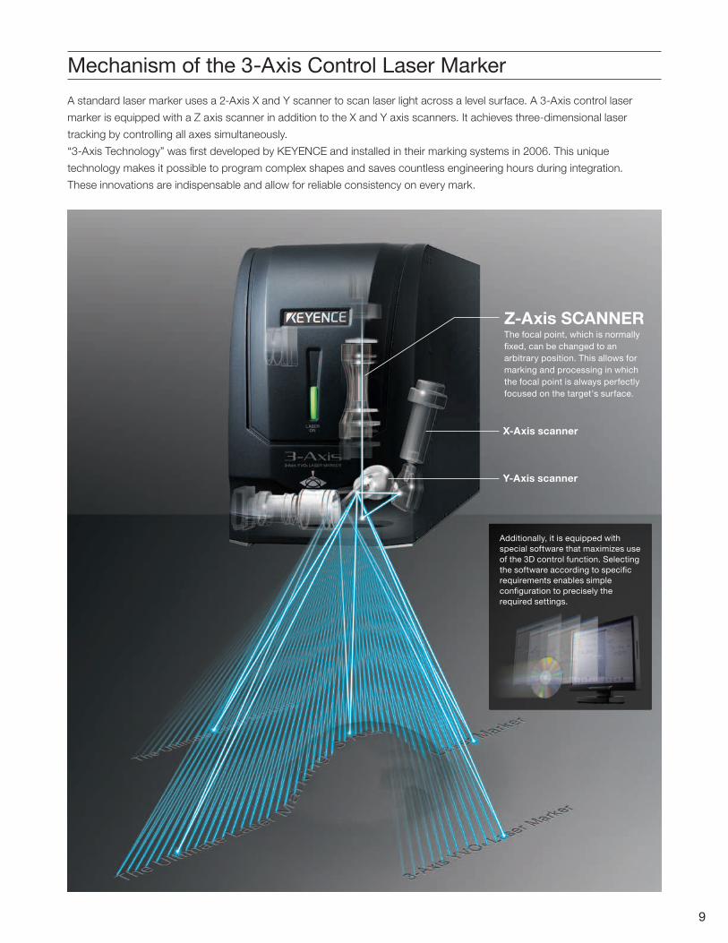
Mechanism of the 3-Axis Control Laser Marker
A standard laser marker uses a 2-Axis X and Y scanner to scan laser light across a level surface. A 3-Axis control laser
marker is equipped with a Z axis scanner in addition to the X and Y axis scanners. It achieves three-dimensional laser
tracking by controlling all axes simultaneously.
“3-Axis Technology” was first developed by KEYENCE and installed in their marking systems in 2006. This unique
technology makes it possible to program complex shapes and saves countless engineering hours during integration.
These innovations are indispensable and allow for reliable consistency on every mark.
Additionally, it is equipped with special software that maximizes use of the 3D control function. Selecting the software according to specific requirements enables simple configuration to precisely the required settings.
Y-Axis scanner
X-Axis scanner
Z-Axis SCANNERThe focal point, which is normally fixed, can be changed to an arbitrary position. This allows for marking and processing in which the focal point is always perfectly focused on the target's surface.

42 mm1.65"
Reference focus position
Position, size or thickness deviates.
Conventional model
Variable focal point
Marking in a set thickness at a set position
3-Axis
10
Marking Builder 2 <Standard Software MB-H2D3> *Optional
Variable spot sizeVarying the spot size of the laser is helpful when trying to enhance the contrast of characters or engraving more deeply into the target surface. Typical defocus techniques may cause varying character size and position, while the 3-Axis Laser Markers can provide uniform quality of characters.
Variable focal lengthThe 3-Axis laser control (X, Y and Z-axes) keeps the laser in focus throughout the focal distance range. This focal length can be set to any position within a 42 mm 1.65" range without distortion across the entire marking area.
LSI (High accuracy marking with defocusing)
Enclosure made of resin (marking on stepped surfaces)

Characters get bolder at the edges
Uniform line width of characters across the area
Conventional model 3-Axis
Conventional model
Edge of the area
3-Axis
11.81"
11.81"
After correction
Head misalignment
Area distortion due to lens characteristics
Area in which deformation and distortion are corrected
Conventional model 3-Axis
11
Spot diameter is kept uniform over the entire areaTraditionally, the spot size at the center and the edge of the marking area were different due to the artificial plane created by the fθ lens. 3-Axis Control Laser Markers solve this problem with X, Y and Z-axis laser control. High accuracy marking on a flat surface is guaranteed because of the uniform spot size.
A single 3-Axis Laser markers covers 7x the area of Conventional models
The 300 mm 11.81" marking area reduces installation costs by eliminating the need for multiple marking heads and mechanical index devices.
The KEYENCE advantage when marking over a wide areaProblems associated with the properties of the F lens of conventional systems have been eliminated, so characters stay clear and crisp over the entire marking area.
Mounting Position CorrectionThe dedicated software easily corrects the head inclination after integration using X, Y and Z-axes, without the need for mechanical adjustment. This feature significantly reduces the man-hours for installation.

Steps
Conventionalmodel
Upper stepLower step Upper stepLower step
Faded characters
3-Axis
Inclined surface
Conventionalmodel
Faded and elongated characters
3-Axis
Cylinder
Conventionalmodel
Distorted and elongated
characters
3-Axis
Circular cone
Conventionalmodel
Character deformation
3-Axis
12
Marking Builder 2 <3D Setting Software MB-H3D2> *Optional
Precise 3-Axis markingThe Software Interface (MB-H3D2) features 3-Axis control to modify the laser position according to the shape of a target, which can include steps, inclined surfaces, cylinders or circular cones and spheres.MB-H3D2 minimizes distorted, worn, or chipped characters while enabling uniform marking on three-dimensional surfaces that are considered untouchable by conventional markers.
Marking comparison
Marks can be viewed and inspected stereoscopically by changing angles at your command.
Programming marking contents to fit a certain shape is as easy as selecting the type of shape from a drop down menu. The marking contents then appears in the 3D programming environment.

13
Auto-FocusUsing the The Software Interface (MB-H3D2) together with a displacement sensor that can measure the distance of the target allows for automatic adjustment of the focal point. In addition, marking and processing can be performed while compensating for changes in material thickness. This not only reduces production costs but also contributes to improvements in quality.
Example of Use for Semiconductors/ Electronic Components Autofocus marking can be used to follow the thickness of the circuit board.
Removing the need for in-process replacement leads to increased marking
quality. Additionally, multi-point measurement enables the curve of circuit boards
or wafers to be accurately followed.
Faded or missing marking occurs when the focal point is misaligned.
Clear printing With the MB-H3D2, 3D setting software, fine adjustments such as auto-focusing and manipulation of the spot diameter of the laser to improve marking clarity can be done on the fly.
Auto-Focus ensures clear printing by always keeping the focal point aligned. This allows for stable marking and processing.
Conventional model 3-Axis

14
Z-MAP Creator <MB-HZM> *Optional (MD-V9000 Series and MD-F3100/5100 Series only)
Perform marking using 3D cad files (.STL) for target profilingFiles with the .stl extension, a commonly used extension in 3D CAD, can be loaded into the KEYENCE Marking Builder software and used as a base for 3D marking. This allows for 3D marking on targets with shapes that cannot be expressed using standard figures implemented by conventional marking software.
2D codes on sloping or uneven surfaces
At first glance this 2D code looks warped and impossible to read, but....
...when viewed from above, the code forms a perfect square and is easily read.
Perfectly focused marks are able to be applied to any surface in the valid marking range. Uninterrupted marking can be performed even on different surfaces without changing fixtures or moving the part.

15
Logo designer <MB-HLD>
Logo designer functionalityLogos can be further manipulated by adding the Logo designer software package to Marking Builder 2. It allows for easy change-over of various patterns via simple software parameters when creating a specific logos, markings and processing patterns. This helps to always create the best marking in the shortest time. Directly importing dxf data makes it possible to edit the logosettings and marking elements. Corrections can be performed easily to create an optimal mark.
Adobe illustrator plug-in *Included with Logo designerA logo created with Adobe Illustrator can be directly imported into the Marker Builder 2 software using the Illustrator Plug-in. The imported logo designs can be fully edited and hatched using the Logo designer software.
Hatching can be easily done on the Marking Builder screen.Create a design with Adobe Illustrator.
Create a logo with Adobe® Illustrator®
* Adobe® Illustrator® is a registered trademark of Adobe Systems Incorporated
The logo can be directly imported into Marking Builder
ContourDiagonalFrame
Hatching functions
Simply select the pattern type, and change the filled marking pattern of the entire logo. This makes it possible to select the optimum marking method to the required look and feel. Fine adjustments, such as line intervals, border offsets and line angles can be changed quickly as well.
Non-connected points are automaticallyrecognized. This makes it possible to makecorrections to the data and change the order that items are marked simply and in a short amount of time.

16
MD-V power distributionPower peaks are concentrated at the center of the beam. Furthermore, ultra-short pulse marking allows for high resolution marking.
Traditional YAG power distributionPeaks of power exist randomly in the beam. Uniformity is often hard to achieve in marking.
MD-V marking photo Traditional YAG marking photo
300x
ITO film (coating removal)
Single mode beam spotThe MD-V utilizes an end-pumping YVO4 laser system that generates an ideal beam spot. Conventional systems are forced
to employ a multi-mode laser, leading to fluctuations in laser power and target quality. Single mode laser’s concentrate the
beam to provide high quality marking on a wide range of surfaces.
High peak power & short pulse laserWith high peak power, MD-V9900 can achieve sharp, high
quality marking on hardened surfaces. This high peak power is
also generated with an incredibly small pulse width, reducing
the possibility of thermal damage to the target surface.
MD-V9900A Series By employing a YVO 4 crystal as it's laser medium, the MD-V Series is able to achieve super-fine, high-speed marking on metals, plastics, and more.

Marking with traditional speed
Laser output (W) Other laser markers
Output stability ±2%
Set value of power
When sped up
MD-V9900A
MD-V9900A
MD-V
Traditional laser
Accurate marking with no space in between
With spaces between dots
A B C A B C
Traditional model without APS
ON
OFF
OFF
The operating life of the LD is dramatically extended.
MD-V with APS
Marking
LD current
Laser power check
13.00W
17
Ultra-high pulse recurrence frequency 400 kHzThe MD-V9900A Series employs a Q switch frequency more
than double that of previous KEYENCE lasers. The high
frequency enables smooth marking of fine resolutions on high
speed productions lines. Both continuous wave and pulse
oscillation are available to accommodate varying surface
conditions.
Automatic power-saving functionThe MD-V9900A Series is equipped with an Auto Power-saving
function (APS), which automatically lowers the current level of
the LD light source when not marking characters. Since only the
current is lowered, and the power of the LD is not turned off, the
system can return to full marking capacity almost instantly.
Built-in power monitorAlong with a system to verify the output value of the laser, the
MD-V9900A also employs an internal system to monitor and
automatically adjust for power variations that may occur over the
lifetime of the laser. This feature will help to ensure that each
mark is made with the same quality and consistency, regardless
of the operator or age of the marking head.
Power linearityThe power linearity of traditional laser systems is typically ±5%,
and could be even larger at low power. The MD-V9900A
achieves an incredible ±2% power stability, meaning that the
mark will never chip, burn, or blur.
Advantages of the built-in power monitor• Automatic power measurement and correction• Quick measurement without additional equipment• No variation caused by individual operators• No change in accuracy over long-term use.

18
50 W
40 W
30 W
20 W
Time
Dep
th
High power output lasers are capable of digging deeper into materials and improving marking times.
*These are representative values. They will vary depending on the material and marking conditions.
The focal distance is changed
after each pass. This allows
for processing with maximum
energy density at all times.
Keyence lasers are optimized for high-speed 2D
barcode marking. An array of various marking
patterns are selectable to ensure that a perminant
mark is applied directly to the products surface in the
least amount of time.
Deep-Engraving
High-Speed 2D Barcode Marking
DEEP ENGRAVINGNEW FUNCTION
MD-F3100/5100 Series
A combination of best-in-class 50 W output and 3-Axis control. Once again, KEYENCE leads the way in cutting edge laser marking technology.
19
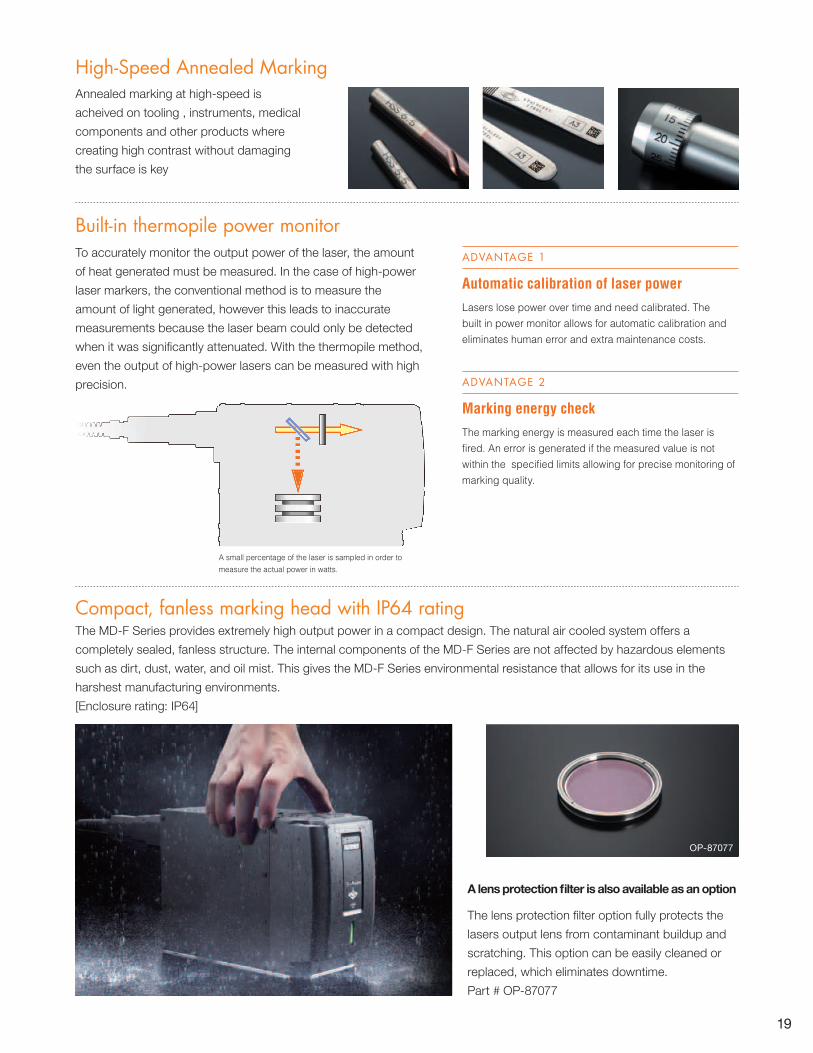
Compact, fanless marking head with IP64 ratingThe MD-F Series provides extremely high output power in a compact design. The natural air cooled system offers a
completely sealed, fanless structure. The internal components of the MD-F Series are not affected by hazardous elements
such as dirt, dust, water, and oil mist. This gives the MD-F Series environmental resistance that allows for its use in the
harshest manufacturing environments.
[Enclosure rating: IP64]
OP-87077
A lens protection filter is also available as an option
The lens protection filter option fully protects the
lasers output lens from contaminant buildup and
scratching. This option can be easily cleaned or
replaced, which eliminates downtime.
Part # OP-87077
Annealed marking at high-speed is
acheived on tooling , instruments, medical
components and other products where
creating high contrast without damaging
the surface is key
High-Speed Annealed Marking
Built-in thermopile power monitor
A small percentage of the laser is sampled in order to measure the actual power in watts.
To accurately monitor the output power of the laser, the amount
of heat generated must be measured. In the case of high-power
laser markers, the conventional method is to measure the
amount of light generated, however this leads to inaccurate
measurements because the laser beam could only be detected
when it was significantly attenuated. With the thermopile method,
even the output of high-power lasers can be measured with high
precision.
Automatic calibration of laser powerLasers lose power over time and need calibrated. The built in power monitor allows for automatic calibration and eliminates human error and extra maintenance costs.
ADVANTAGE 1
Marking energy checkThe marking energy is measured each time the laser is fired. An error is generated if the measured value is not within the specified limits allowing for precise monitoring of marking quality.
ADVANTAGE 2

20
Guide laser functionBy scanning a safe, visible red laser in the pattern of the marking area or the
marking contents, positioning of the target and fixture can be adjusted quickly
and easily.
High-speed 30 W marking capabilitiesThe ML-Z9500 Series precisely marks characters on rapidly
moving flat or curved surfaces. The deep focal range of the
ML-Z means that there's no need to adjust for varying product
sizes, reducing overall tact time. This allows the maximum
performance of the marking head to be utilized in a wide range
of applications.
Guide laserWork areaguide laser
ML-Z9500 Series
The synergy between 30 Watts of output power and an ultra-high-speed scanning system significantly improves productivity.

Too close
In focus
* The focal point can be adjusted according to the pointer position at any distance.
21
9.3 µm short wavelength laserThe ML-Z9500 series are available in a 9.3 um
short wavelength version. This allows for
better heat absorption for certain materials like
PET and PC. The 9.3 μm short wavelength
laser clearly marks characters of high visibility
at shallow depths, with fewer edges,
guaranteeing high quality in marking and
processing.
Barcode information checkThe HR Series compares the barcode information read with the barcode
information registered in the system. The detected barcode can be automatically
fed into the ML-Z and either used to change program or change the data being
marked.
Flexible board Film cutting
Reasons for high quality marking and processing
There is a lot of damage, and the surface is inscribed roughly.
Conventional model ML-Z
Edge
Depth
9.3 μm laser10.6 μm laserEdge
Depth
Working distance pointerThe visible red laser beams allow users to view the optimum working distance on
the target without physically measuring. This also helps to quickly indicate
misalignments during production use.

22
DEDICATED TO ADDING VALUE FOR OUR CUSTOMERS
Direct ApproachOur technically trained sales engineers have extensive experience with various applications and industries. Sales
engineers specialize within a certain product group to become experts in their fields. This experience and specialization
allows the most efficient solution to be recommended to customers.
In some cases, the application may require the design of a new product. KEYENCE is able to quickly incorporate input
from customers into our new product designs since we manufacture the products as well. More than 1,500 sales engineers
around the world are prepared to participate at every level of our customers’ business, from the design and research stage
to the production line and beyond.
Comprehensive SupportKEYENCE supports customers with extensive on-site manufacturing and automation knowledge. Recommending the right
solutions for our customers’ applications is only the beginning of how our sales engineers assist customers.
After purchasing a product, KEYENCE sales engineers ensure the products are functioning optimally, and they are able to
go on-site if needed. If a customer ever has any questions, sales engineers and our technical support team are available
to answer them quickly.
Customer KEYENCEDirect Consultation
Quick Response
KEYENCE Direct Sales System
Conventional Sales Style
Customer Distributor Sales Agent Manufacturer
Selection Adoption After-Sales Support
Comprehensive SupportCustomer
KEYENCE
CONSULTATIVE APPROACH

23
Fast DeliveryKEYENCE’s fast delivery system will ensure that customers
get their required products when they need them. Products
are shipped from warehouse centers in Japan, Singapore,
Malaysia, Thailand, China, Taiwan, South Korea, U.S.
(Chicago), Canada, Mexico, the U.K., Germany, France and
Italy or from 200 agents in 44 countries.
Worldwide Direct Sales Network More than 200 offices in 44 countries
When working with KEYENCE, you’ll not only receive the
industry’s most advanced products, but you can also
count on a worldwide network of highly trained support
engineers to guide you through the implementation of
those products. Whether you’re working in the US, or
shipping a machine to Eastern Europe, Asia, Mexico, or
other remote locations, KEYENCE provides support you
can count on.
CanadaKEYENCE CANADA INC.
Portland
Seattle
NorthernCalifornia
AtlantaDallas
Austin
Monterrey
Leon
Ciudad Juárez
Tijuana
Denver
Birmingham
Chicago
Boston
New Jersey
Los Angeles
Indianapolis
St. Louis
Minneapolis
Tampa
Detroit
GrandRapids
ClevelandKEYENCE CORPORATIONOF AMERICA
Cincinnati
Nashville
Richmond
Raleigh
Montreal
Knoxville
Greenville
Philadelphia
Louisville
Charlotte
KEYENCE MEXICO S.A. DE C.V.
Kansas city
RochesterMilwaukee
Chicago
MEXICO
CANADAUSA
EXTENSIVE NETWORK
KEYENCE(UK)
LIMITED
KEYENCE CORPORATIONOF AMERICA
KEYENCESINGAPORE PTE LTD.
KEYENCE (MALAYSIA) SDN BHD
KEYENCE INDIA PVT. LTD.
KEYENCE(THAILAND)
CO., LTD.
KEYENCEDEUTSCHLAND GmbH
KEYENCE TAIWANCO., LTD.
KOREA KEYENCE CO., LTD.
KEYENCE FRANCE SAS KEYENCE
CORPORATIONKEYENCE
(HONG KONG) CO., LTD.
KEYENCE (CHINA) CO., LTD.
KEYENCE ITALIA S.p.A.
KEYENCE CANADA INC.
KEYENCE MEXICOS.A. DE C.V.
KEYENCE BRASIL
KEYENCE INTERNATIONAL (BELGIUM) NV/SA
KEYENCE Corporate Offices
Distributors

24
Standard model Standard model/Viewfinder Wide area model
ModelMain unit (controller + marking head) MD-V9900FA MD-V9910FA MD-V9920FA
Console MC-P1Marking style XYZ 3-Axis simultaneous scanning method
Marking laserYVO4 laser, Class 4 Laser Product (IEC60825-1), Class IV Laser Product (FDA (CDRH) Part1040.10)
Wavelength 1,064 nmOutput of Laser Oscillator (Typical) 10 W
Q-switch frequency CW (continuous wave), 1 to 400 kHzGuide laser / working distance pointer Semiconductor laser, Class 2 Laser Product (IEC60825-1), Class II Laser Product (FDA (CDRH) Part1040.10)
Wavelength 655 nmOutput 1.0 mW
Marking area 120 x 120 x 42 mm 4.72" x 4.724" x 1.65" 300 x 300 x 42 mm 11.81" x 11.81" x 1.65" Basic working distance ( ±variation width) 189 mm (±21 mm) 7.44" (±0.83") 300 mm (±21 mm) 11.81" (±0.83") Marking resolution 2 µm 0.78 Mil 5 µm 0.197 Mil Scan speed 12000 mm/s max. 8000 mm/s max.
Character type
Font KEYENCE original font (numerical value, alphabet, katakana, hiragana and kanji) / user font / true type fontBarcode CODE39 / ITF / 2of5 / NW7 (CODABAR) / JAN / CODE1282D code QR code / micro QR code / DataMatrix (ECC200/GS1 DataMatrix)
GS1 DataBar GS1 DataBar (Truncated)/GS1 DataBar (Truncated) CC-A/GS1 DataBar Stacked/GS1 DataBar Stacked CC-A/GS1 DataBar Limited/GS1 DataBar Limited CC-A
Logo image Custom font, logo (CAD) data BMP / JPEG / PNG / TIFLaser cutting Fixed point / straight line / dashed line / oval
Marking conditions
Marking style Stationary marking / movement marking (constant speed / encoder)Character size (height / width) 0.1 to 120 mm 0.004" to 4.72" 0.1 to 300 mm 0.004" to 11.81"
ProgramRegistered programs 2000 settings max.Number of blocks 256 blocks
Input / Output Terminal block input and output / MIL connector input and outputInterface RS-232C/RS-422A/USB2.0 *1
CF memory card slot Dedicated for CF memory card *2
Marking unit installation direction All directionsMarking unit cable length 5 m 16.4' Cooling method Forced air cooling
Supply voltage 100 to 120 VAC, 700 VA max. 50/60 Hz200 to 240 VAC, 800 VA max. 50/60 Hz
Environmental resistance
Ambient temperature for storage -10 to +60°C -50 to +140°F, No condensationAmbient temperature for usage 0 to +40°C 32 to +104°FRelative humidity for usage 30 to 85%, No condensation
WeightController 23.0 kg 23.2 kg 23.0 kgMarking head unit 11.5 kg 11.8 kg 11.5 kgConsole 2.0 kg
*1 The USB port is dedicated for PC software. *2 SanDisk cards are recommended.
PC SOFTWARE SPECIFICATIONS (OPTIONAL)*3
Model Overview
Marking Builder 2 (2D) MB-H2D3-DVD 2D setting and editing software (focal distance, tilt correction, spot variation, distance pointer adjustment)Marking Builder 2 (3D)*4 MB-H3D2 3D setting and editing software (marking on plane, cylinder, cone, or sphere; Z-Axis movement marking)Logo designer*4 MB-HLD Software tool that converts DXF files into logo or custom character files and edits them.Z-MAP Creator*4 MB-HZM Software tool that creates Z-MAP files from 3D CAD files (STL).
*3 • Supported OS: Windows 7/Vista (SP1 or higher)/XP (SP3 or higher)• Supported language: Japanese, English, Chinese (Simplified) and German (Chinese supports the simplified Chinese display, but does not support Chinese input.)
For Windows 7/Vista, the 32 bit and 64 bit version are available. For Windows XP, only the 32 bit version is available.• Windows is a registered trademark of Microsoft corporation in the U.S.A.
*4 2D setting and editing software MB-H2D3-DVD must be installed and the USB hardware key is required.
SPECIFICATIONS (MD-V9900A Series)
Working distance
6 x M6, Depth 8 0.32" max.Mounting hole
131 (Lid for filter replacement)
22
102.7
(300)
50
ø81140.8
150 150 79
125
6.7
145
230
415
116.5
5.71"
9.06"
16.34"
4.59"0.87" 1.97"
4.04"
5.54"
3.11"
0.26"
ø3.19"
5.91" 5.91"
4.92"
5.16"
(11.81")
210
330 29
422
(30) 4056
(250)43
(R110)382
41.5
19280
4 x M4, Depth 6 0.24" max.(With rubber legs removed.)
4 x ø30
(1.18") 15.94"
16.61"
0.75"
11.02"
ø1.18"
8.27"
0.24"
12.99" 1.14"
(9.84")
15.04"
(R4.33")
1.63"1.69"
(283)(11.14") (58)(2.28")
(1.85")48 1.89"
(47)
(203 7.99")
190 7.48"
933.66"
1295.08"
270 10.63"
171 6.73"(Effective display area)
(Effective display area)
Cable length: 5 m 16.4'
Head Controller
Console MC-P1
DIMENSIONS Unit: mm inch

25
PC SOFTWARE SPECIFICATIONS (OPTIONAL)*6
30 W 50 W Standard area Wide area Standard area Wide area
ModelMarking unit (Controller + Head) MD-F3100
MD-F3100C*1MD-F3120MD-F3120C*1
MD-F5100MD-F5100C*1
MD-F5120MD-F5120C*1
Console (sold separately) MC-P1Marking method XYZ 3-Axis simultaneous scanning method
Marking laserYb: Fiber laser (Class 4 Laser product; IEC 60825-1, FDA (CDRH) part 1040.10)*5
Wavelength 1090 nmOutput 30 W 50 W
Pulse frequency 60 to 120 kHzGuide laser/Working distance pointer Semiconductor laser, Wavelength: 655 nm, output: 1.0 mW (Class 2 Laser product; IEC 60825-1, FDA (CDRH) part 1040.10)*5
Marking area 120 × 120 × 42 mm 4.72" × 4.72" × 1.65" 300 × 300 × 42 mm 11.81" × 11.81" × 1.65" 120 × 120 × 42 mm 4.72" × 4.72" × 1.65" 300 × 300 × 42 mm 11.81" × 11.81" × 1.65"Standard working distance (±variable width) 168 mm (± 21 mm) 6.61" (± 0.83") 300 mm (± 21 mm) 11.81" (± 0.83") 168 mm (± 21 mm) 6.61" (± 0.83") 300 mm (± 21 mm) 11.81" (± 0.83")Marking resolution 2 μm 0.08 Mil 5 μm 0.20 Mil 2 μm 0.08 Mil 5 μm 0.20 MilScan speed Max. 12000 mm/s 472.44"/s Max. 8000 mm/s 314.96"/s Max. 12000 mm/s 472.44"/s Max. 8000 mm/s 314.96"/s
Character type
Font KEYENCE original font (numbers, letters, katakana, hiragana, kanji), User font, True Type fontBarcode CODE39, ITF, 2of5, NW7 (CODABAR), JAN, EAN, UPC, CODE1282D code QR code, micro QR code, DataMatrix (ECC200/GS1 DataMatrix)
GS1 DataBar GS1 DataBar, GS1 DataBar CC-A, GS1 DataBar Stacked, GS1 DataBar Stacked CC-A,GS1 DataBar Limited, GS1 DataBar Limited CC-A
Logo image Custom character font and logo CAD data (DXF), BMP/JPEG/PNG/TIF Machinery operation Fixed point, straight line, dashed line, circle, oval
Marking conditions
Workpiece style Stationary marking, movement marking (constant, encoder) Character size (marking height/width) 0.1 to 120 mm 0.004" to 4.72" 0.1 to 300 mm 0.004" to 11.81" 0.1 to 120 mm 0.004" to 4.72" 0.1 to 300 mm 0.004" to 11.81"Pro-gram
No. of registered programs Max. 2000 programs No. of program blocks 256 blocks
I/O (input-output) Terminal block I/O, MIL connector I/O, connector control I/O*2
Interfaces RS-232C, RS-422A, USB 2.0,*3 Ethernet (100BASE-TX/10BASE-T)CF memory card slot Dedicated for compact flash memory card use*4
Head installation direction All directionsHead cable length 4 m 13.12'Cooling method Controller: Forced air cooling Head: Natural air coolingRated voltage and power consumption 100 to 120 VAC/200 to 240 VAC ±10%, 50/60 Hz, Max. 550 VA 100 to 120 VAC/200 to 240 VAC ±10%, 50/60 Hz, Max. 750 VAOvervoltage category IIPollution degree 2Enclosure rating (Head) IP64
Environmen-tal resistance
Ambient temperature for storage -10 to 60°C (no freezing) 14 to 140°FAmbient temperature for usage 0 to 40°C 32 to 104°FAmbient humidity for storage
30 to 85% (No condensation)Ambient humidity for usage
WeightController 27.0 kg 27.5 kg Head 6.7 kg Console 2.0 kg
*1. Type equipped with contactor control terminal block *2. Supported models: MD-F3100C/3120C, 5100C/5120C *3. The USB port is dedicated for PC software. *4. We recommend SanDisk cards.*5. The laser classification for FDA (CDRH) is implemented based on IEC 60825-1 in accordance with the requirements of Laser Notice No. 50.
Model OverviewMarking Builder 2 (2D) MB-H2D3-DVD 2D setting and editing software (on the DVD) (focal distance, tilt correction, spot variation, distance pointer adjustment)Marking Builder 2 (3D)*7 MB-H3D2 3D setting and editing software (marking on plane, cylinder, cone, or sphere; Z-Axis movement marking)Logo designer*7 MB-HLD Software tool that converts DXF files into logo or custom character files and edits them. Z-MAP Creator*7 MB-HZM Software tool that creates Z-MAP files from 3D CAD files (STL).
*6 • Supported OS: Windows 7/Vista (SP1 or higher)/XP (SP3 or higher)• Supported language: Japanese, English, Chinese (Simplified) and German (Chinese supports the simplified Chinese display, but does not support Chinese input.)
For Windows 7/Vista, the 32 bit and 64 bit version are available. For Windows XP, only the 32 bit version is available.• Windows is a registered trademark of Microsoft corporation in the U.S.A.
*7 2D setting and editing software MB-H2D3-DVD must be installed and the USB hardware key is required.
178
Working distance
115
146.5
28
ø4 ø0.16" depth MAX 8 0.32"
Positioning hole(2 locations)
4 × M6 depth MAX 6 0.24"Attaching hole
140(133.8)70
203.8
10 120
80
ø102 ø4.02" replacement cover glass hole
4056
(30)(150)
42
65.4
257.5
4-M4 depth MAX 6 0.24"(when plastic feet are removed)
29330
210
194-ø30
280
422
Head Controller
Console MC-P1
4.53" 10.24"
9.06"8.02"
(5.27")5.51"
2.76"
3.15"
0.39" 4.72"
(8.27")1.10"
5.77"16.61"
0.75"
7.01"
11.02"ø1.18"
(1.18")
0.24"15.94"
1.65"
(5.91") 2.57"
10.14"
8.27"
12.99"1.14"
(283)(11.14") (58)(2.28")
(1.85")48 1.89"
(47)
(203) (7.99")
190 7.48"
933.66"
1295.08"
270 10.63"
171 6.73"(Effective display area)
(Effective display area)
Cable length: 5 m 16.4'
230
260 (210)
DIMENSIONS Unit: mm inch
MD-F SeriesSAFETY PRECAUTIONS
• Be sure to read the manual and fully understand its contents before using the product.
• Do not allow your eyes or skin to be exposed to a directly irradiated laser beam or a diffused reflection laser beam.
178
Working distance
115
146.5
28
ø4 ø0.16" depth MAX 8 0.32"
Positioning hole(2 locations)
4 × M6 depth MAX 6 0.24"Attaching hole
140(133.8)70
203.8
10 120
80
ø102 ø4.02" replacement cover glass hole
4056
(30)(150)
42
65.4
257.5
4-M4 depth MAX 6 0.24"(when plastic feet are removed)
29330
210
194-ø30
280
422
Head Controller
Console MC-P1
4.53" 10.24"
9.06"8.02"
(5.27")5.51"
2.76"
3.15"
0.39" 4.72"
(8.27")1.10"
5.77"16.61"
0.75"
7.01"
11.02"ø1.18"
(1.18")
0.24"15.94"
1.65"
(5.91") 2.57"
10.14"
8.27"
12.99"1.14"
(283)(11.14") (58)(2.28")
(1.85")48 1.89"
(47)
(203) (7.99")
190 7.48"
933.66"
1295.08"
270 10.63"
171 6.73"(Effective display area)
(Effective display area)
Cable length: 5 m 16.4'
230
260 (210)
Head Controller
Console MC-P1
SPECIFICATIONS (MD-F3100/5100 Series)
26
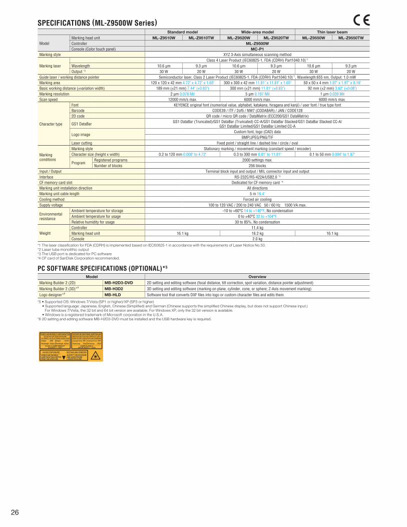
Standard model Wide-area model Thin laser beam
ModelMarking head unit ML-Z9510W ML-Z9510TW ML-Z9520W ML-Z9520TW ML-Z9550W ML-Z9550TW Controller ML-Z9500WConsole (Color touch panel) MC-P1
Marking style XYZ 3-Axis simultaneous scanning method
Marking laserClass 4 Laser Product (IEC60825-1, FDA (CDRH) Part1040.10)*1
Wavelength 10.6 µm 9.3 µm 10.6 µm 9.3 µm 10.6 µm 9.3 µmOutput *2 30 W 20 W 30 W 20 W 30 W 20 W
Guide laser / working distance pointer Semiconductor laser, Class 2 Laser Product (IEC60825-1, FDA (CDRH) Part1040.10)*1, Wavelength:655 nm, Output: 1.0 mW Marking area 120 x 120 x 42 mm 4.72" x 4.72" x 1.65" 300 x 300 x 42 mm 11.81" x 11.81" x 1.65" 50 x 50 x 4 mm 1.97" x 1.97" x 0.16"Basic working distance (±variation width) 189 mm (±21 mm) 7.44" (±0.83") 300 mm (±21 mm) 11.81" (±0.83") 92 mm (±2 mm) 3.62" (±0.08")Marking resolution 2 µm 0.078 Mil 5 µm 0.197 Mil 1 µm 0.039 Mil Scan speed 12000 mm/s max. 6000 mm/s max. 6000 mm/s max.
Character type
Font KEYENCE original font (numerical value, alphabet, katakana, hiragana and kanji) / user font / true type fontBarcode CODE39 / ITF / 2of5 / NW7 (CODABAR) / JAN / CODE1282D code QR code / micro QR code / DataMatrix (ECC200/GS1 DataMatrix)
GS1 DataBar GS1 DataBar (Truncated)/GS1 DataBar (Truncated) CC-A/GS1 DataBar Stacked/GS1 DataBar Stacked CC-A/GS1 DataBar Limited/GS1 DataBar Limited CC-A
Logo imageCustom font, logo (CAD) data
BMP/JPEG/PNG/TIFLaser cutting Fixed point / straight line / dashed line / circle / oval
Marking conditions
Marking style Stationary marking / movement marking (constant speed / encoder)Character size (height x width) 0.2 to 120 mm 0.008" to 4.72" 0.3 to 300 mm 0.01" to 11.81" 0.1 to 50 mm 0.004" to 1.97"
ProgramRegistered programs 2000 settings max.Number of blocks 256 blocks
Input / Output Terminal block input and output / MIL connector input and outputInterface RS-232C/RS-422A/USB2.0 *3
CF memory card slot Dedicated for CF memory card *4
Marking unit installation direction All directionsMarking unit cable length 5 m 16.4' Cooling method Forced air coolingSupply voltage 100 to 120 VAC / 200 to 240 VAC 50 / 60 Hz 1500 VA max.
Environmental resistance
Ambient temperature for storage -10 to +60°C 14 to +140°F, No condensationAmbient temperature for usage 0 to +40°C 32 to +104°FRelative humidity for usage 30 to 85%, No condensation
WeightController 11.4 kgMarking head unit 16.1 kg 16.2 kg 16.1 kgConsole 2.0 kg
*1 The laser classification for FDA (CDRH) is implemented based on IEC60825-1 in accordance with the requirements of Laser Notice No.50.*2 Laser tube monolithic output*3 The USB port is dedicated for PC software*4 CF card of SanDisk Corporation recommended.
PC SOFTWARE SPECIFICATIONS (OPTIONAL)*5
Model Overview
Marking Builder 2 (2D) MB-H2D3-DVD 2D setting and editing software (focal distance, tilt correction, spot variation, distance pointer adjustment)Marking Builder 2 (3D)*6 MB-H3D2 3D setting and editing software (marking on plane, cylinder, cone, or sphere; Z-Axis movement marking)Logo designer*6 MB-HLD Software tool that converts DXF files into logo or custom character files and edits them.
*5 • Supported OS: Windows 7/Vista (SP1 or higher)/XP (SP3 or higher) • Supported language: Japanese, English, Chinese (Simplified) and German (Chinese supports the simplified Chinese display, but does not support Chinese input.) For Windows 7/Vista, the 32 bit and 64 bit version are available. For Windows XP, only the 32 bit version is available. • Windows is a registered trademark of Microsoft corporation in the U.S.A.*6 2D setting and editing software MB-H2D3-DVD must be installed and the USB hardware key is required.
SPECIFICATIONS (ML-Z9500W Series)
27
40
1805.5
360
280
ø216 4 x -
5.5 370 32.2
Laser power cable
57 280
120
30
213
ø8 16.4' 5 m
0.22" 14.57" 1.27"
8.39"
98
241.4193.8
23.9
88.6143.5
50
133
181
18.7451.77" 0.74"
9.50"7.63"
40.2 1.58"21 0.83"
3.49"
5.65"
0.94"
3.86"
7.13"
5.24"
1.97"
ø0.32"
11.02"2.24"
4.72"
1.18"
0.24" ø0.83"
14.17"
11.02"
1.57"
0.22" 7.09"
* Working distance
Distance pointer
175
659
300
286 329
146.5
175
138
284
5
165
83 11019.4
ø62
155
10
69.4
24 2
ø2.44"
12.95"11.26"
25.94"0.94"
11.18"
6.10"
0.39" 3.27" 4.33"
11.81"
6.50"
0.20"
5.43"
6.89"
0.08"
0.76"
2.73"
6.89"5.77"
* Working distance
175
659
300
286 329
146.5
175
284
138
5
165155
10
57.6
83 110
24 2
ø85
11.18"
6.10"
0.39" 3.27" 4.33"
11.81"
6.50"
0.20"
5.43"
2.27"
ø3.35"
12.95"11.26"
25.94"0.94"
6.89"
0.08"
6.89"5.77"
* Working distance
Distance pointer
ML-Z9510
ML-Z9520
ML-Z9550
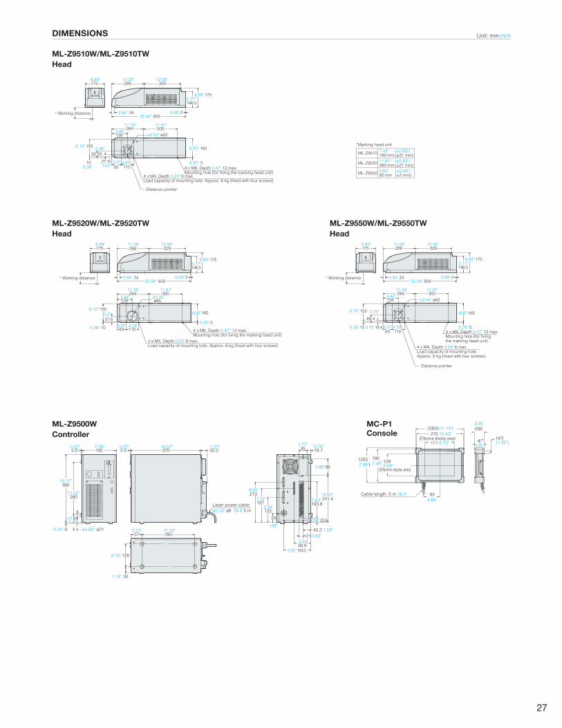
189 mm (±21 mm)
300 mm (±21 mm)
92 mm (±2 mm)
7.44" (±0.83")
11.81" (±0.83")
3.62" (±0.08")
*Marking head unit
286
24
329
2
138
284ø52
300
155
10
62.55
27.1583 110
5
165
4 x M6, Depth 0.47" 12 max.Mounting hole (for fixing the marking head unit)
4 x M6, Depth 0.47"" 12 max.Mounting hole (for fixing the marking head unit)
4 x M6, Depth 0.47" 12 max.Mounting hole (for fixing the marking head unit)
4 x M4, Depth 0.24" 6 max.Load capacity of mounting hole: Approx. 6 kg (fixed with four screws)
4 x M4, Depth 0.24" 6 max.Load capacity of mounting hole: Approx. 6 kg (fixed with four screws) 4 x M4, Depth 0.24" 6 max.
Load capacity of mounting hole: Approx. 6 kg (fixed with four screws)
175
659
146.5
175
11.18"
6.10"
0.39" 1.07"
2.46"
3.27" 4.33"
11.81"
ø2.05"
6.50"
0.20"
5.43"
12.95"11.26"
25.94"0.94"
6.89"
0.08"
6.89"5.77"
(283)(11.14") (58)(2.28")
(1.85")48 1.89"
(47)
(203 7.99")
190 7.48"
933.66"
1295.08"
270 10.63"
171 6.73"(Effective display area)
(Effective display area)
Cable length: 5 m 16.4'
DIMENSIONS
ML-Z9510W/ML-Z9510TWHead
40
1805.5
360
280
ø216 4 x -
5.5 370 32.2
Laser power cable
57 280
120
30
213
ø8 16.4' 5 m
0.22" 14.57" 1.27"
8.39"
98
241.4193.8
23.9
88.6143.5
50
133
181
18.7451.77" 0.74"
9.50"7.63"
40.2 1.58"21 0.83"
3.49"
5.65"
0.94"
3.86"
7.13"
5.24"
1.97"
ø0.32"
11.02"2.24"
4.72"
1.18"
0.24" ø0.83"
14.17"
11.02"
1.57"
0.22" 7.09"
* Working distance
Distance pointer
175
659
300
286 329
146.5
175
138
284
5
165
83 11019.4
ø62
155
10
69.4
24 2
ø2.44"
12.95"11.26"
25.94"0.94"
11.18"
6.10"
0.39" 3.27" 4.33"
11.81"
6.50"
0.20"
5.43"
6.89"
0.08"
0.76"
2.73"
6.89"5.77"
* Working distance
175
659
300
286 329
146.5
175
284
138
5
165155
10
57.6
83 110
24 2
ø85
11.18"
6.10"
0.39" 3.27" 4.33"
11.81"
6.50"
0.20"
5.43"
2.27"
ø3.35"
12.95"11.26"
25.94"0.94"
6.89"
0.08"
6.89"5.77"
* Working distance
Distance pointer
ML-Z9510
ML-Z9520
ML-Z9550
189 mm (±21 mm)
300 mm (±21 mm)
92 mm (±2 mm)
7.44" (±0.83")
11.81" (±0.83")
3.62" (±0.08")
*Marking head unit
286
24
329
2
138
284ø52
300
155
10
62.55
27.1583 110
5
165
4 x M6, Depth 0.47" 12 max.Mounting hole (for fixing the marking head unit)
4 x M6, Depth 0.47"" 12 max.Mounting hole (for fixing the marking head unit)
4 x M6, Depth 0.47" 12 max.Mounting hole (for fixing the marking head unit)
4 x M4, Depth 0.24" 6 max.Load capacity of mounting hole: Approx. 6 kg (fixed with four screws)
4 x M4, Depth 0.24" 6 max.Load capacity of mounting hole: Approx. 6 kg (fixed with four screws) 4 x M4, Depth 0.24" 6 max.
Load capacity of mounting hole: Approx. 6 kg (fixed with four screws)
175
659
146.5
175
11.18"
6.10"
0.39" 1.07"
2.46"
3.27" 4.33"
11.81"
ø2.05"
6.50"
0.20"
5.43"
12.95"11.26"
25.94"0.94"
6.89"
0.08"
6.89"5.77"
(283)(11.14") (58)(2.28")
(1.85")48 1.89"
(47)
(203 7.99")
190 7.48"
933.66"
1295.08"
270 10.63"
171 6.73"(Effective display area)
(Effective display area)
Cable length: 5 m 16.4'
ML-Z9520W/ML-Z9520TWHead
ML-Z9500WController
MC-P1Console
ML-Z9550W/ML-Z9550TWHead
40
1805.5
360
280
ø216 4 x -
5.5 370 32.2
Laser power cable
57 280
120
30
213
ø8 16.4' 5 m
0.22" 14.57" 1.27"
8.39"
98
241.4193.8
23.9
88.6143.5
50
133
181
18.7451.77" 0.74"
9.50"7.63"
40.2 1.58"21 0.83"
3.49"
5.65"
0.94"
3.86"
7.13"
5.24"
1.97"
ø0.32"
11.02"2.24"
4.72"
1.18"
0.24" ø0.83"
14.17"
11.02"
1.57"
0.22" 7.09"
* Working distance
Distance pointer
175
659
300
286 329
146.5
175
138
284
5
165
83 11019.4
ø62
155
10
69.4
24 2
ø2.44"
12.95"11.26"
25.94"0.94"
11.18"
6.10"
0.39" 3.27" 4.33"
11.81"
6.50"
0.20"
5.43"
6.89"
0.08"
0.76"
2.73"
6.89"5.77"
* Working distance
175
659
300
286 329
146.5
175
284
138
5
165155
10
57.6
83 110
24 2
ø85
11.18"
6.10"
0.39" 3.27" 4.33"
11.81"
6.50"
0.20"
5.43"
2.27"
ø3.35"
12.95"11.26"
25.94"0.94"
6.89"
0.08"
6.89"5.77"
* Working distance
Distance pointer
ML-Z9510
ML-Z9520
ML-Z9550
189 mm (±21 mm)
300 mm (±21 mm)
92 mm (±2 mm)
7.44" (±0.83")
11.81" (±0.83")
3.62" (±0.08")
*Marking head unit
286
24
329
2
138
284ø52
300
155
10
62.55
27.1583 110
5
165
4 x M6, Depth 0.47" 12 max.Mounting hole (for fixing the marking head unit)
4 x M6, Depth 0.47"" 12 max.Mounting hole (for fixing the marking head unit)
4 x M6, Depth 0.47" 12 max.Mounting hole (for fixing the marking head unit)
4 x M4, Depth 0.24" 6 max.Load capacity of mounting hole: Approx. 6 kg (fixed with four screws)
4 x M4, Depth 0.24" 6 max.Load capacity of mounting hole: Approx. 6 kg (fixed with four screws) 4 x M4, Depth 0.24" 6 max.
Load capacity of mounting hole: Approx. 6 kg (fixed with four screws)
175
659
146.5
175
11.18"
6.10"
0.39" 1.07"
2.46"
3.27" 4.33"
11.81"
ø2.05"
6.50"
0.20"
5.43"
12.95"11.26"
25.94"0.94"
6.89"
0.08"
6.89"5.77"
(283)(11.14") (58)(2.28")
(1.85")48 1.89"
(47)
(203 7.99")
190 7.48"
933.66"
1295.08"
270 10.63"
171 6.73"(Effective display area)
(Effective display area)
Cable length: 5 m 16.4'
Unit: mm inch

MARKING SOLUTIONS
Visit our expert engineering website to get the latest
marking technology information and successful
applications for your industry.
www.marking-central.com
KA1-1083
� Regional offices COFLGAIL
DenverTampaAtlantaChicago
ALCACA
BirminghamN.CaliforniaLos Angeles
TXVAWAWI
DallasRichmondSeattleMilwaukee
SCTNTNTX
GreenvilleKnoxvilleNashvilleAustin
www.keyence.com
KEYENCE MEXICO S.A. DE C.V.PHONE: +52-81-8220-7900 FAX: +52-81-8220-9097 E-mail: [email protected]
INKSKYMA
IndianapolisKansas CityLouisvilleBoston
MIMIMNMO
DetroitGrand RapidsMinneapolisSt. Louis
NJNYNCNC
Elmwood ParkRochesterCharlotteRaleigh
OHOHORPA
CincinnatiClevelandPortlandPhiladelphia
Copyright (c) 2013 KEYENCE CORPORATION. All rights reserved. 3Axis-KA-C-US 1093-4 611714 Printed in Japan
KEYENCE CANADA INC.Head Office PHONE: 905-366-7655 FAX: 905-366-1122 E-mail: [email protected] PHONE: 514-694-4740 FAX: 514-694-3206
KEYENCE CORPORATION OF AMERICACorporate Office 669 River Drive, Suite 403, Elmwood Park, NJ 07407 PHONE: 888-539-3623 FAX: 855-539-0123 E-mail: [email protected] & Marketing Head Office 1100 North Arlington Heights Road, Suite 210, Itasca, IL 60143 PHONE: 888-539-3623 FAX: 855-539-0123
KEYENCE CORPORATION1-3-14, Higashi-Nakajima, Higashi-Yodogawa-ku, Osaka, 533-8555, Japan PHONE: +81-6-6379-2211
SAFETY INFORMATIONPlease read the instruction manual carefully in order to safely operate any KEYENCE product.
The information in this publication is based on KEYENCE’s internal research/evaluation at the time of release and is subject to change without notice.
1 - 8 8 8 - 5 3 9 - 3 6 2 31-888-KEYENCE
CALL TOLL FREE
T O C O N TA C T Y O U R L O C A L O F F I C E
* 6 1 1 7 1 4 *