24 G3VM- BR ER E
10
G3VM-@BR@/@ER@ DIP 1 G3VM-@BR@/@ER@ MOS FET Relays DIP 6-pin, High-current and Low-ON-resistance Type MOS FET Relays in DIP 6-pin packages that achieve the low ON resistance and high switching capacity of a mechanical relay • Load voltage: 20 V, 30 V, 40 V, 60 V, or 100 V • 20-V Relay: Continuous load current of 4 A (8 A) max. * • 30-V Relay: Continuous load current of 5 A (10 A) max. * • 40-V Relay: Continuous load current of 3.5 A (7 A) max. * • 60-V Relay: Continuous load current of 4 A (8 A) max. * • 100-V Relay: Continuous load current of 3.5 A (7 A) max. * * Values in parentheses are for connection C. ■Application Examples ■Ordering Information * The AC peak and DC value are given for the load voltage and continuous load current. Note: To order tape packaging for Relays with surface-mounting terminals, add “(TR)” to the end of the model number. RoHS Compliant ■Package (Unit : mm, Average) ■Model Number Legend Package Contact form Load voltage (peak value) * Continuous load current (peak value) * Stick packaging Tape packaging Model Minimum package quantity Model Minimum package quantity Connection A, B Connection C PCB Terminals Surface-mounting Terminals Surface-mounting Terminals DIP6 1a (SPST-NO) 20 V 4 A 8 A G3VM-21BR G3VM-21ER 50 pcs. G3VM-21ER(TR) 1,500 pcs. 30 V 5 A 10 A G3VM-31BR G3VM-31ER G3VM-31ER(TR05) 500 pcs. 40 V 3.5 A 7 A G3VM-41BR G3VM-41ER G3VM-41ER(TR) 1,500 pcs. 60 V 2.5 A − G3VM-61BR G3VM-61ER G3VM-61ER(TR) 3 A 6 A G3VM-61BR1 G3VM-61ER1 G3VM-61ER1(TR) 4 A 8 A G3VM-61BR2 G3VM-61ER2 G3VM-61ER2(TR05) 500 pcs. 100 V 2 A 4 A G3VM-101BR G3VM-101ER G3VM-101ER(TR) 1,500 pcs. 3.5 A 7 A G3VM-101BR1 G3VM-101ER1 G3VM-101ER1(TR05) 500 pcs. Note: The actual product is marked differently from the image shown here. • Communication equipment • Test & Measurement equipment • Security equipment • Industrial equipment DIP 6-pin Note: The actual product is marked differently from the image shown here. PCB Terminals Surface-mounting Terminals 6.4 7.12 3.65 6.4 7.12 3.65 G3VM- @ @ @ @ @ 1 2 3 4 5 1. Load Voltage 2 : 20 V 3 : 30 V 4 : 40 V 6 : 60 V 10 : 100 V 5. Other informations When specifications overlap, serial code is added in the recorded order. 2. Contact form 1 : 1a (SPST-NO) 3. Package B : DIP 6-pin with PCB terminals E : DIP 6-pin with surface-mounting terminals 4. Additional functions R: Low ON resistance
Transcript of 24 G3VM- BR ER E

G3V
M-@
BR@
/@E
R@
DIP
1
G3VM-@BR@/@ER@MOS FET Relays DIP 6-pin, High-current and Low-ON-resistance Type
MOS FET Relays in DIP 6-pin packages that achieve the low ON resistance and high switching capacity of a mechanical relay• Load voltage: 20 V, 30 V, 40 V, 60 V, or 100 V
• 20-V Relay: Continuous load current of 4 A (8 A) max. *• 30-V Relay: Continuous load current of 5 A (10 A) max. *• 40-V Relay: Continuous load current of 3.5 A (7 A) max. *• 60-V Relay: Continuous load current of 4 A (8 A) max. *• 100-V Relay: Continuous load current of 3.5 A (7 A) max. ** Values in parentheses are for connection C.
■Application Examples
■Ordering Information
* The AC peak and DC value are given for the load voltage and continuous load current.Note: To order tape packaging for Relays with surface-mounting terminals, add “(TR)” to the end of the model number.
RoHS Compliant
■Package (Unit : mm, Average) ■Model Number Legend
PackageContact
formLoad voltage
(peak value) *
Continuous load current (peak value) *
Stick packaging Tape packaging
Model Minimum package quantity
Model Minimum package quantity
Connection A, B
Connection C
PCB TerminalsSurface-mounting
TerminalsSurface-mounting
Terminals
DIP61a
(SPST-NO)
20 V 4 A 8 A G3VM-21BR G3VM-21ER
50 pcs.
G3VM-21ER(TR) 1,500 pcs.
30 V 5 A 10 A G3VM-31BR G3VM-31ER G3VM-31ER(TR05) 500 pcs.
40 V 3.5 A 7 A G3VM-41BR G3VM-41ER G3VM-41ER(TR)
1,500 pcs.
60 V
2.5 A − G3VM-61BR G3VM-61ER G3VM-61ER(TR)
3 A 6 A G3VM-61BR1 G3VM-61ER1 G3VM-61ER1(TR)
4 A 8 A G3VM-61BR2 G3VM-61ER2 G3VM-61ER2(TR05) 500 pcs.
100 V2 A 4 A G3VM-101BR G3VM-101ER G3VM-101ER(TR) 1,500 pcs.
3.5 A 7 A G3VM-101BR1 G3VM-101ER1 G3VM-101ER1(TR05) 500 pcs.
Note: The actual product is marked differently from the image shown here.
• Communication equipment
• Test & Measurement equipment
• Security equipment
• Industrial equipment
DIP 6-pin
Note: The actual product is marked differently from the image shown here.
PCB Terminals
Surface-mounting Terminals
6.4
7.12
3.65
6.4
7.12
3.65
G3VM-@ @ @ @ @1 2 3 4 5
1. Load Voltage2 : 20 V
3 : 30 V
4 : 40 V
6 : 60 V
10 : 100 V
5. Other informationsWhen specifications overlap, serial code is
added in the recorded order.
2. Contact form1 : 1a (SPST-NO)
3. PackageB : DIP 6-pin with PCB terminals
E : DIP 6-pin with surface-mounting
terminals
4. Additional functionsR: Low ON resistance

2
G3VM-@BR@/@ER@ MOS FET RelaysD
IPG
3VM
-@B
R@
/@E
R@
■Absolute Maximum Ratings (Ta = 25°C)
* The dielectric strength between the input and output was checked by applying voltage between all pins as a group on the LED side and all pins as a group on thelight-receiving side.
Item SymbolG3VM-21BRG3VM-21ER
G3VM-31BRG3VM-31ER
G3VM-41BRG3VM-41ER
G3VM-61BRG3VM-61ER
G3VM-61BR1G3VM-61ER1
G3VM-61BR2G3VM-61ER2
G3VM-101BRG3VM-101ER
G3VM-101BR1G3VM-101ER1
UnitMeasurement
conditions
Inpu
t
LED forward current IF 30 mA
Repetitive peak LED forward current
IFP 1 A100 μs pulses, 100 pps
LED forward current reduction rate
ΔIF/°C -0.3 mA/°C Ta ≥ 25°C
LED reverse voltage VR 5 6 5 6 5 6 V
Connection temperature TJ 125 °C
Out
put
Load voltage (AC peak/DC) VOFF 20 30 40 60 100 V
Continuous load current
Connection A
IO4 5 3.5
2.53 4 2 3.5
A
Connection A: AC peak/DCConnection B and C: DC
Connection B−
Connection C 8 10 7 6 8 4 7
ON current reduction rate
Connection A
ΔIO/°C-40 -50 -35
-22-30 -40 -20 -35
mA/°C Ta ≥ 25°CConnection B−
Connection C -80 -100 -70 -60 -80 -40 -70
Pulse ON current lop 12 15 10.5 7.5 9 12 6 10.5 At=100 ms, Duty=1/10
Connection temperature TJ 125 °C
Dielectric strength between I/O * VI-O 2,500 Vrms AC for 1 min
Ambient operating temperature
Ta -40 to +85 -40 to +110 -40 to +85 -20 to +85 -40 to +85 -40 to +110 -40 to +85 -40 to +110 °C With no icing or condensation
Ambient storage temperature Tstg -55 to +125 -40 to +125 -55 to +125 °C
Soldering temperature − 260 °C 10 s
Connection Diagram
Note: Only connection A can be used for the G3VM-61BR/ER.
Connection A
Connection B
Connection C
Load
or AC DC
1
2
3
6
5
4
1
2
3
6
5
4
DC
Load
Load
DC
1
2
3
6
5
4

3
G3VM-@BR@/@ER@ MOS FET Relays
G3V
M-@
BR@
/@E
R@
DIP
■Electrical Characteristics (Ta = 25°C)
Item Symbol G3VM-21BRG3VM-21ER
G3VM-31BRG3VM-31ER
G3VM-41BRG3VM-41ER
G3VM-61BRG3VM-61ER
G3VM-61BR1G3VM-61ER1
G3VM-61BR2G3VM-61ER2
G3VM-101BRG3VM-101ER
G3VM-101BR1G3VM-101ER1
UnitMeasurement
conditions
Inpu
t
LED forward voltage VF
Minimum 1.18 1.5 1.18 1.5 1.18 1.5
V IF=10 mATypical 1.33 1.64 1.33 1.64 1.33 1.64
Maximum 1.48 1.8 1.48 1.8 1.48 1.8
Reverse current IR Maximum 10 μA VR=5 V
Capacitance between terminals
CT Typical 70 pF V=0, f=1 MHz
Trigger LED forward current
IFT
Typical 0.5 0.2 0.5 1 0.5 0.3 0.5 0.2mA IO=1 A
Maximum 3
Release LED forward current
IFC Minimum 0.1 0.01 0.1 0.01 0.1 0.01 mA IOFF=10 μA
Out
put
Maximum resistance with output ON
Connection A
RON
Typical 20 30 65 40 35 100 50
mΩ
G3VM-21BR/21ER/41BR/41ER/61BR1/61ER1/101BR/101ER: IF=5 mA,Io=2 AG3VM-61BR/61ERIF=10 mA, t=10 ms, Io=2 AG3VM-31BR/31ER/61BR2/61ER2/101BR1/101ER1:IF=5 mA Io=3 A t < 1s
Maximum 50 40 60 100 70 60 200 80
Connection B
Typical 10 15
−
20 18 50 24
G3VM-21BR/21ER/41BR/41ER/61BR1/61ER1/101BR/101ER: IF=5 mA, Io=2 AG3VM-31BR/31ER: IF=5 mA, Io=5 A, t < 1sG3VM-61BR2/61ER2: IF=5 mA, Io=4 A, t < 1sG3VM-101BR1/101ER1: IF=5 mA, Io=3.5 A, t < 1s
Connection C
Typical 5 8 10 9 25 12
G3VM-21BR/21ER/41BR/41ER/61BR1/61ER1/101BR/101ER: IF=5 mA, Io=4 A, t<1sG3VM-31BR/31ER:IF=5 mA, Io=10 A, t < 1sG3VM-61BR2/61ER2: IF=5 mA, Io=8 A, t < 1sG3VM-101BR1/101ER1:IF=5 mA, Io=7 A, t < 1s
Current leakage when the relay is open
ILEAKTypical − 0.01 − 0.001 − 0.01 − 0.01 μA
VOFF=Load voltage ratingsMaximum 1 0.01 1
Capacitance between terminals
COFF Typical 1000 1100 1000 400 1100 640 1000 450 pF V=0, f=1 MHz
Capacitance between I/O terminals
CI-O Typical 0.8 pF f=1 MHz, VS=0 V
Insulation resistance between I/O terminals
RI-OMinimum 1000
MΩ VI-O=500 VDC, ROH ≤ 60%Typical 108
Turn-ON time tON
Typical 2.5 0.8 2 3 2 1.2 2 0.8
ms IF=5 mA, RL=200 Ω,VDD=20 V *
Maximum 5 1.5 5
Turn-OFF time tOFF
Typical 0.1 0.6 0.1
Maximum 1 0.5 1 0.2 1 0.5 1 0.5
* Turn-ON and Turn-OFF Times
VOUT
IF
tON tOFF
10%90%
IF 1
2
6
4
RLVDD
VOUT
4
G3VM-@BR@/@ER@ MOS FET RelaysD
IPG
3VM
-@B
R@
/@E
R@
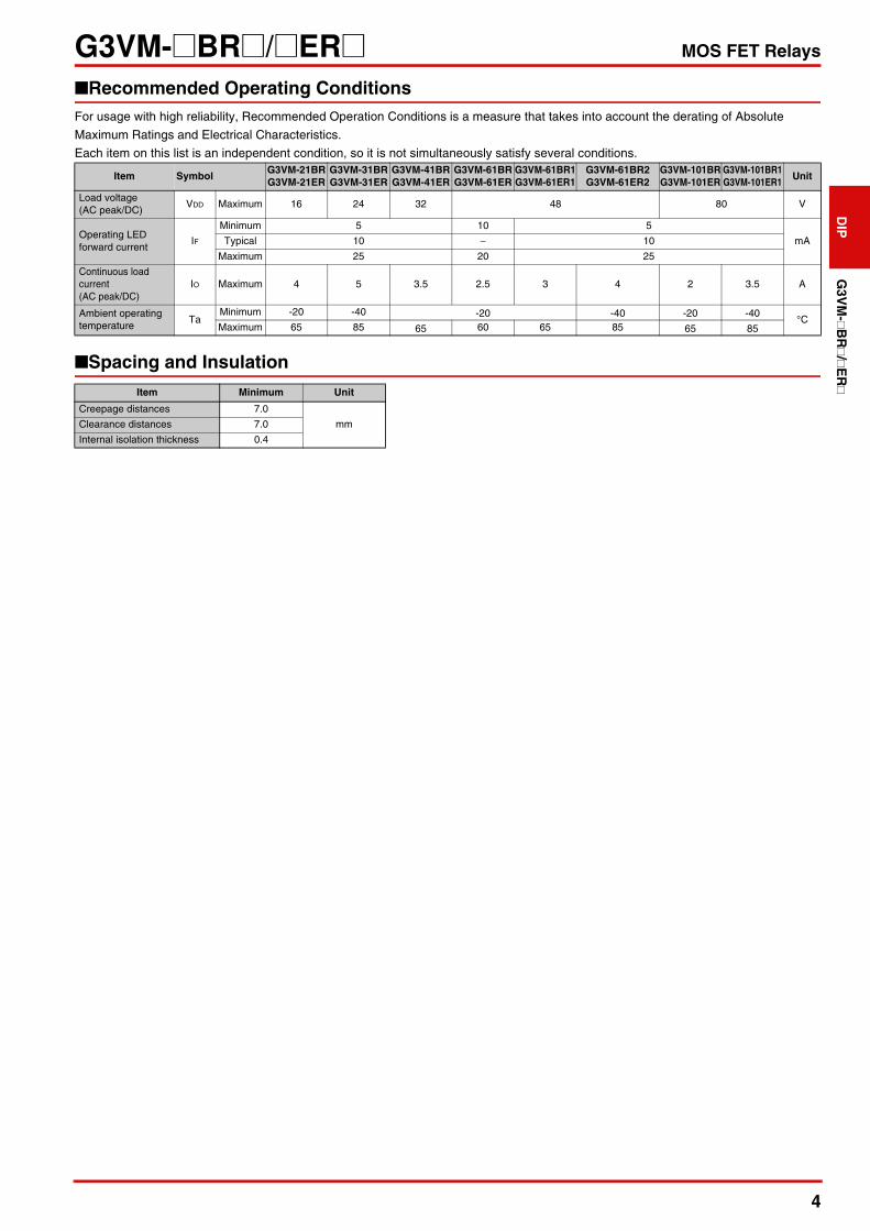
■Recommended Operating ConditionsFor usage with high reliability, Recommended Operation Conditions is a measure that takes into account the derating of Absolute
Maximum Ratings and Electrical Characteristics.
Each item on this list is an independent condition, so it is not simultaneously satisfy several conditions.
■Spacing and Insulation
Item SymbolG3VM-21BRG3VM-21ER
G3VM-31BRG3VM-31ER
G3VM-41BRG3VM-41ER
G3VM-61BRG3VM-61ER
G3VM-61BR1G3VM-61ER1
G3VM-61BR2G3VM-61ER2
G3VM-101BRG3VM-101ER
G3VM-101BR1G3VM-101ER1
Unit
Load voltage (AC peak/DC)
VDD Maximum 16 24 32 48 80 V
Operating LED forward current
IF
Minimum 5 10 5
mA Typical 10 − 10
Maximum 25 20 25
Continuous load current (AC peak/DC)
IO Maximum 4 5 3.5 2.5 3 4 2 3.5 A
Ambient operating temperature
Ta Minimum -20 -40 -20 -40 -20 -40
°CMaximum 65 85 65 60 65 85 65 85
Item Minimum Unit
Creepage distances 7.0
mmClearance distances 7.0
Internal isolation thickness 0.4

5
G3VM-@BR@/@ER@ MOS FET Relays
G3V
M-@
BR@
/@E
R@
DIP
■Engineering Data
● LED forward current vs.Ambient temperatureG3VM-21BR/21ER/41BR/41ER/
61BR1/61ER1/101BR/101ERG3VM-61BR/61ER G3VM-31BR/31ER/61BR2/61ER2/
101BR1/101ER1
● LED forward current vs. LED forward voltageG3VM-21BR/21ER/41BR/41ER/61BR/
61ER/61BR1/61ER1/101BR/101ERG3VM-31BR/31ER/61BR2/61ER2/
101BR1/101ER1
● Continuous load current vs. Ambient temperatureG3VM-21BR/21ER/41BR/41ER
G3VM-61BR1/61ER1/101BR/101ER G3VM-61BR/61ER G3VM-31BR/31ER/61BR2/61ER2/101BR1/101ER1
IF - Ta
Ambient temperature Ta (°C)-40 100806040200-20
0
5
10
15
20
25
30
35
LED
forw
ard
curr
ent I
F (
mA
)
IF - Ta
Ambient temperature Ta (°C)100806040200-20
0
5
10
15
20
25
30
35
LED
forw
ard
curr
ent I
F (
mA
)
IF - Ta
Ambient temperature Ta (°C)
-40 120100806040200-200
5
10
15
20
25
30
35
LED
forw
ard
curr
ent I
F (
mA
)
IF - VF
LED forward voltage VF (V)
100
10
1
0.1
0.010.8 1 1.2 1.4 1.6
LED
forw
ard
curr
ent I
F (
mA
)
Ta=25°C
G3VM-21BR/21ER/41BR/41ER61BR1/61ER1/101BR/101ER
G3VM-61BR/ER
IF - VF100
10
1
0.11.5 2.01.0
LED forward voltage VF (V)
Ta=-40°C
Ta=25°C
Ta=85°C
LED
forw
ard
curr
ent I
F (
mA
)
IO - Ta
Ambient temperature Ta (°C)
-40 -20 100 80 60 40 0 20
Con
tinuo
us lo
ad c
urre
nt IO
(A
)
0
1
2
3
4
5
6
7
8
9
10
G3VM-21BR/ER: Connection C G3VM-41BR/ER: Connection C
G3VM-21ER/ER: Connection A, B
G3VM-41BR/ER: Connection A, B
IO - Ta
Ambient temperature Ta (°C)
-40 -20 100 80 60 40 0 20
Con
tinuo
us lo
ad c
urre
nt IO
(A
)
0
1
2
3
4
5
6
7
8
9
10
G3VM-61BR1/ER1: Connection C
G3VM-101BR/ER: Connection C
G3VM-21ER/ER: Connection A, B
G3VM-41BR/ER: Connection A, B
IO - Ta
Ambient temperature Ta (°C)
-20 100 80 60 40 0 20
Con
tinuo
us lo
ad c
urre
nt IO
(A
)
0
1
2
3
4
5
6
7
8
9
10IO - Ta
-20-40 120 100 80 60 40 0 20
Ambient temperature Ta (°C)
0
2
4
6
8
12
10G3VM-31BR/ER: Connection C
G3VM-61BR2/ER2: Connection C
G3VM-101BR1/ER1: Connection C
G3VM-31BR/ER: Connection A, B
G3VM-101BR1/ER1: Connection A, B
G3VM-61BR2/ER2: Connection A, B
Con
tinuo
us lo
ad c
urre
nt IO
(A
)

6
G3VM-@BR@/@ER@ MOS FET RelaysD
IPG
3VM
-@B
R@
/@E
R@
■Engineering Data
● Continuous load current vs. On-state voltageG3VM-21BR/21ER/41BR/41ER/61BR/
61ER/61BR1/61ER1/101BR/101ERG3VM-31BR/31ER/61BR2/61ER2/
101BR1/101ER1
● On-state resistance vs. Ambient temperatureG3VM-21BR/21ER/41BR/41ER/61BR/
61ER/61BR1/61ER1/101BR/101ER
G3VM-31BR/31ER/61BR2/61ER2/101BR1/101ER1
● Trigger LED forward current vs. Ambient temperatureG3VM-21BR/21ER/41BR/41ER/61BR/
61ER/61BR1/61ER1/101BR/101ERG3VM-31BR/31ER/61BR2/61ER2/
101BR1/101ER1
● Turn ON, Turn OFF time vs. LED forward currentG3VM-21BR/21ER/41BR/41ER G3VM-61BR/61ER/61BR1/61ER1/
101BR/101ERG3VM-31BR/31ER/61BR2/61ER2/
101BR1/101ER1
IO - VON
On-state voltage VON (V)-0.2 -0.1 0.10 0.2
-5
-2
-3
-4
-1
0
3
2
1
4
5
Con
tinuo
us lo
ad c
urre
nt IO
(A
)
G3VM-21BR/ER
G3VM-41BR/ER
G3VM-61BR1/ER1
G3VM-101BR/ER
G3VM-61BR/ER
G3VM-61BR/ER: Ta=25°C, IF=10mAThe others: Ta=25°C, IF=5mA, Connection A
-0.2 0.1-0.1 0.0 0.2-5
-2
-3
-4
-1
0
3
2
1
4
5
G3VM-31BR/ER
G3VM-61BR2/ER2
G3VM-101BR1/ER1
IO - VON
Ta=25°C, IF=5mA, t<1s Connection A
On-state voltage VON (V)
Con
tinuo
us lo
ad c
urre
nt IO
(A
)
RON - Ta
Ambient temperature Ta (°C)
-40 -20 10080 60 40 0 20
On-
stat
e re
sist
ance
RO
N (
mΩ
)
0
50
100
150
G3VM-21BR/ER G3VM-41BR/ER
G3VM-61BR1/ER1
G3VM-101BR/ER
G3VM-61BR/ER
G3VM-61BR/ER: IO=2A, IF=10mAThe others: IO=2A, IF=5mA, t<1s, Connection A
RON - Ta
-40 -20 12010080 60 40 0 20
On-
stat
e re
sist
ance
RO
N (
mΩ
)
Ambient temperature Ta (°C)
0
50
100
150
G3VM-101BR1/ER1
G3VM-61BR2/ER2
G3VM-31BR/ER
Io=Contiuous load current ratings, IF=5mA, t<1s, Connection A
IFT - Ta
Ambient temperature Ta (°C)
-40 -20 100 80 60 40 0 20
Trig
ger
LED
forw
ard
curr
ent I
FT (
mA
)
0
0.5
1
1.5
2
2.5
3
3.5
G3VM-21BR/ER
G3VM-41BR/ER
G3VM-61BR1/ER1
G3VM-61BR/ERG3VM-61BR/ER: IO=2AThe others: IO=1A, t<1s, Connection A
G3VM-101BR/ER
IFT - Ta
-40 -20 100 120 80 60 40 0 20
Trig
ger
LED
forw
ard
curr
ent I
FT (
mA
)
0
0.5
1
1.5
2
G3VM-101BR1/ER1
G3VM-31BR/ER
G3VM-61BR2/ER2
IO=1A, t<1s, Connection A
Ambient temperature Ta (°C)
tON, tOFF - IF
LED forward current IF (mA)
101 1000.01
0.1
1
10
100
Turn
ON
, Tur
n O
FF
tim
e tO
N, t
OF
F (
ms)
tON
tOFF
G3VM-41BR/ER
G3VM-21BR/ER
G3VM-41BR/ER
VDD=20V, RL=200Ω, Ta=25°C
tON, tOFF - IF
LED forward current IF (mA)
101 1000.01
0.1
1
10
100
Turn
ON
, Tur
n O
FF
tim
e tO
N, t
OF
F (
ms)
tON
tOFFtOFF
tON
G3VM-61BR1/ER1
G3VM-101BR/ER
G3VM-61BR/ER
G3VM-61BR1/ER1
G3VM-101BR/ER
VDD=20V, RL=200Ω, Ta=25°C
tON, tOFF - IF
101 1000.01
0.1
1
10
Turn
ON
, Tur
n O
FF
tim
e tO
N, t
OF
F (
ms)
tON
tOFF
G3VM-31BR/ER
G3VM-61BR2/ER2
G3VM-101BR1/ER1
VDD=20V, RL=200Ω, Ta=25°C
LED forward current IF (mA)
7
G3VM-@BR@/@ER@ MOS FET Relays
G3V
M-@
BR@
/@E
R@
DIP
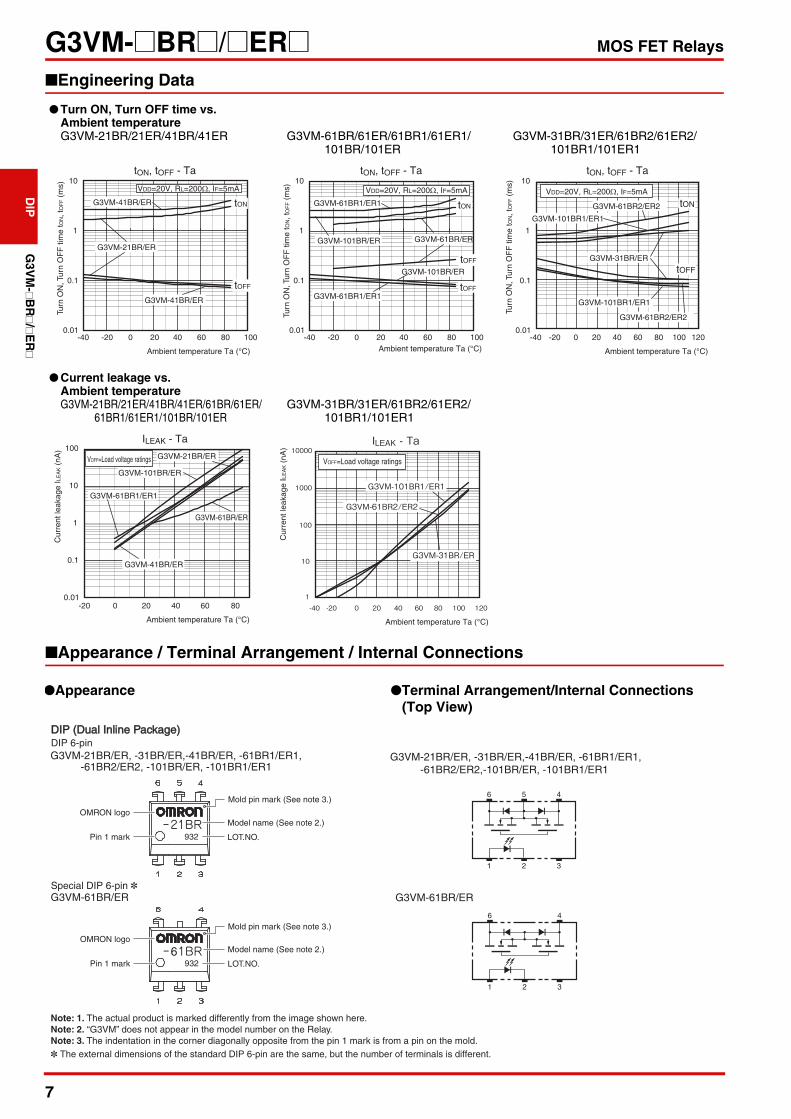
■Engineering Data
■Appearance / Terminal Arrangement / Internal Connections
● Turn ON, Turn OFF time vs. Ambient temperatureG3VM-21BR/21ER/41BR/41ER G3VM-61BR/61ER/61BR1/61ER1/
101BR/101ERG3VM-31BR/31ER/61BR2/61ER2/
101BR1/101ER1
● Current leakage vs. Ambient temperatureG3VM-21BR/21ER/41BR/41ER/61BR/61ER/
61BR1/61ER1/101BR/101ERG3VM-31BR/31ER/61BR2/61ER2/
101BR1/101ER1
tON, tOFF - Ta
Ambient temperature Ta (°C)
-40 -20 10080 60 40 0 20
Turn
ON
, Tur
n O
FF
tim
e tO
N, t
OF
F (
ms)
0.01
0.1
1
10
tOFF
tON G3VM-41BR/ER
G3VM-21BR/ER
G3VM-41BR/ER
VDD=20V, RL=200Ω, IF=5mA
tON, tOFF - Ta
Ambient temperature Ta (°C)-40 -20 10080 60 40 0 20
Turn
ON
, Tur
n O
FF
tim
e tO
N, t
OF
F (
ms)
0.01
0.1
1
10
tOFF
tON G3VM-61BR1/ER1
G3VM-101BR/ER
G3VM-61BR/ER
G3VM-61BR1/ER1
G3VM-101BR/ER
tOFF
VDD=20V, RL=200Ω, IF=5mA
tON, tOFF - Ta
-40 -20 12010080 60 40 0 20
Ambient temperature Ta (°C)
0.01
0.1
1
10
tOFF
tONG3VM-61BR2/ER2
G3VM-61BR2/ER2
G3VM-31BR/ER
G3VM-101BR1/ER1
G3VM-101BR1/ER1
VDD=20V, RL=200Ω, IF=5mA
Turn
ON
, Tur
n O
FF
tim
e tO
N, t
OF
F (
ms)
ILEAK - Ta
Ambient temperature Ta (°C)
-20 80 60 40 0 200.01
100
10
1
0.1
VOFF=Load voltage ratings G3VM-21BR/ER
G3VM-41BR/ER
G3VM-61BR1/ER1
G3VM-101BR/ER
G3VM-61BR/ER
Cur
rent
leak
age
ILE
AK (
nA)
ILEAK - Ta
-40 -20 80 60 12010040 0 201
10000
1000
100
10G3VM-31BR/ER
G3VM-61BR2/ER2
G3VM-101BR1/ER1
Ambient temperature Ta (°C)
VOFF=Load voltage ratings
Cur
rent
leak
age
ILE
AK (
nA)
●Appearance ●Terminal Arrangement/Internal Connections(Top View)
DIP 6-pinDIP (Dual Inline Package)DIP (Dual Inline Package)
OMRON logo
Pin 1 mark
Model name (See note 2.)
LOT.NO.932
G3VM-21BR/ER, -31BR/ER,-41BR/ER, -61BR1/ER1, -61BR2/ER2, -101BR/ER, -101BR1/ER1
Mold pin mark (See note 3.)
G3VM-21BR/ER, -31BR/ER,-41BR/ER, -61BR1/ER1, -61BR2/ER2,-101BR/ER, -101BR1/ER1
6 5 4
1 32
OMRON logo
Pin 1 mark
Model name (See note 2.)
LOT.NO.932
G3VM-61BR/ERSpecial DIP 6-pin *
Mold pin mark (See note 3.)
6
* The external dimensions of the standard DIP 6-pin are the same, but the number of terminals is different.
G3VM-61BR/ER
6 4
1 32
Note: 1. The actual product is marked differently from the image shown here.Note: 2. “G3VM” does not appear in the model number on the Relay.Note: 3. The indentation in the corner diagonally opposite from the pin 1 mark is from a pin on the mold.

8
G3VM-@BR@/@ER@ MOS FET RelaysD
IPG
3VM
-@B
R@
/@E
R@
■Dimensions (Unit: mm)
G3VM-21BR/31BR/41BR/61BR1/61BR2/ G3VM-21ER/31ER/41ER/61ER1/61ER2/
101BR/101BR1 101ER/101ER1
G3VM-61BR G3VM-61ER
■Approved StandardsUL recognized
■Safety Precautions• Refer to the Common Precautions for All MOS FET Relays for precautions that apply to all MOS FET Relays.
PCB Dimensions (BOTTOM VIEW)
Actual Mounting Pad Dimensions(Recommended Value, Top View)
Note: The actual product is marked differently from the image shown here.
PCB Dimensions (BOTTOM VIEW)
Actual Mounting Pad Dimensions(Recommended Value, Top View)
Note: The actual product is marked differently from the image shown here.
Approved Standards Contact form File No.
UL (recognized) 1a (SPST-NO) E80555
PCB TerminalsWeight: 0.4 g
7.12±0.25
6.4±0.25
2.54±0.25
1.2±0.15
0.5±0.1
0.8±0.257.62±0.25
7.85 to 8.80
3.65+0.15-0.25
0.25+0.1-0.05
2.5 min.
Surface-mounting TerminalsWeight: 0.4 g
7.12±0.25
6.4±0.25
2.54±0.25
1.2±0.15
7.62±0.25
10.0 max.1.0 min.
1.0 min.
3.65+0.15-0.25 4.0+0.25
-0.2
Six, 0.8-dia. holes
2.54
2.54
(0.61)
(0.61)
(1.52) (1.52)
8.3 to 8.8
2.54 2.54
1.51.3
9
G3VM-@BR@/@ER@ MOS FET Relays
G3V
M-@
BR@
/@E
R@
DIP
OMRON CorporationElectronic and Mechanical Components Company
Regional Contact
Cat. No. K303-E1-020618(0318)(O)
Americas Europehttps://www.components.omron.com/ http://components.omron.eu/
Asia-Pacific China https://ecb.omron.com.sg/ https://www.ecb.omron.com.cn/
Korea Japanhttps://www.omron-ecb.co.kr/ https://www.omron.co.jp/ecb/
In the interest of product improvement, specifications are subject to change without notice.© OMRON Corporation 2018 All Rights Reserved.
Please check each region's Terms & Conditions by region website.

Mouser Electronics
Authorized Distributor
Click to View Pricing, Inventory, Delivery & Lifecycle Information: Omron:
G3VM-31ER G3VM-61ER2(TR05) G3VM-31BR G3VM-101ER1(TR05) G3VM-101ER1 G3VM-31ER(TR05) G3VM-
101BR1 G3VM-61BR2 G3VM-61ER2 G3VM-101AR1 G3VM-101DR1 G3VM-101DR1(TR05) G3VM-201AR G3VM-
201DR G3VM-201DR(TR05) G3VM-31AR G3VM-31DR G3VM-31DR(TR05) G3VM-61AR1 G3VM-61DR1 G3VM-
61DR1(TR05)