2016 Owner’s Manual
136
2016 Owner’s Manual
Transcript of 2016 Owner’s Manual

2016 Owner’s Manual
California Proposition 65 Warning
This product contains or emits chemicals known to the state of California to cause cancer and
birth defects or other reproductive harm.
Batteries, battery posts, terminals and related accessories contain lead and lead
compounds, and other chemicals known to the State of California to cause cancer and birth defects or other reproductive harm.
WASH HANDS AFTER HANDLING.
For videos and more information about a safe riding experience with your
POLARIS SLINGSHOT vehicle, scan this QR code with your smartphone.

1
2016 Owner’s Manual
SLINGSHOT®
SLINGSHOT® SL
2
Copyright 2015 Polaris Industries Inc. All information contained within this publication is based on the latest product information available at the time of publication. Product improvements or other changes may result in differences between this manual and the vehicle. Depictions and/or procedures in this publication are intended for reference use only.No liability can be accepted for omissions or inaccuracies. Polaris Industries reserves the right to make changes at any time, without notice and without incurring obligation to make the same or similar changes to vehicles previously built. Any reprinting or reuse of the depictions and/or procedures contained within, whether whole or in part, is expressly prohibited.POLARIS® and SLINGSHOT® are trademarks of Polaris Industries Inc.dexos® and dexos1® are registered trademarks owned by General Motors, LLCDEX-COOL® is a registered trademark of General Motors CorporationiPhone®, iPod®, iPod nano®, and iPod touch® are trademarks of Apple Inc., registered in the U.S. and other countries.The Bluetooth® word mark and logos are registered trademarks owned by Bluetooth SIG, Inc. and any use of such marks by POLARIS is under license. Other trademarks and trade names are those of their respective owners.Pandora®, the Pandora logo and the Pandora trade dress are trademarks or registered trademarks of Pandora Media, Inc. Used with permission. Printed in U.S.A.P/N 9926666
The SLINGSHOT vehicle is NOT a car.The SLINGSHOT vehicle complies with Federal Motor Vehicle Safety Standards (FMVSS) and
regulations of the United States Department of Transportation (DOT) applicable to
motorcycles in the USA.The SLINGSHOT vehicle does NOT comply
with Federal Motor Vehicle Safety Standards (FMVSS) and regulations of the United States
Department of Transportation (DOT) applicable to passenger cars in the USA.
3
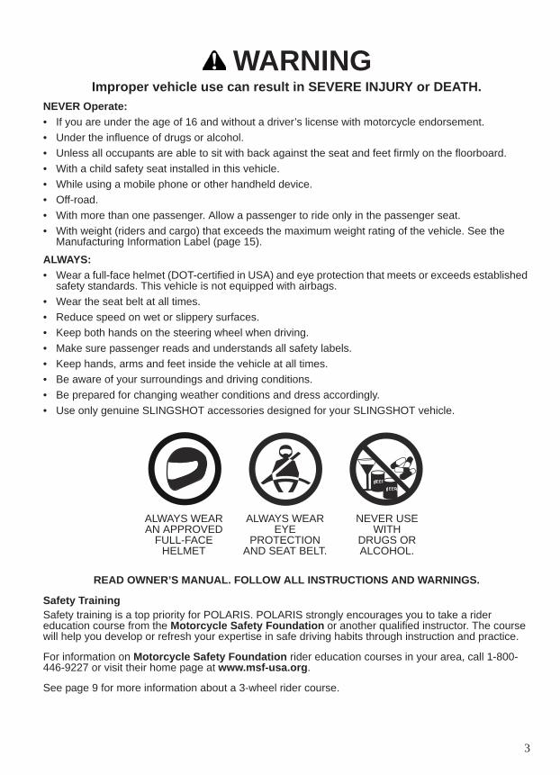
WARNINGImproper vehicle use can result in SEVERE INJURY or DEATH.
NEVER Operate:• If you are under the age of 16 and without a driver’s license with motorcycle endorsement.• Under the influence of drugs or alcohol.• Unless all occupants are able to sit with back against the seat and feet firmly on the floorboard.• With a child safety seat installed in this vehicle.• While using a mobile phone or other handheld device.• Off-road.• With more than one passenger. Allow a passenger to ride only in the passenger seat.• With weight (riders and cargo) that exceeds the maximum weight rating of the vehicle. See the
Manufacturing Information Label (page 15).
ALWAYS:• Wear a full-face helmet (DOT-certified in USA) and eye protection that meets or exceeds established
safety standards. This vehicle is not equipped with airbags.• Wear the seat belt at all times.• Reduce speed on wet or slippery surfaces.• Keep both hands on the steering wheel when driving.• Make sure passenger reads and understands all safety labels.• Keep hands, arms and feet inside the vehicle at all times.• Be aware of your surroundings and driving conditions.• Be prepared for changing weather conditions and dress accordingly.• Use only genuine SLINGSHOT accessories designed for your SLINGSHOT vehicle.
READ OWNER’S MANUAL. FOLLOW ALL INSTRUCTIONS AND WARNINGS.
Safety TrainingSafety training is a top priority for POLARIS. POLARIS strongly encourages you to take a rider education course from the Motorcycle Safety Foundation or another qualified instructor. The course will help you develop or refresh your expertise in safe driving habits through instruction and practice.
For information on Motorcycle Safety Foundation rider education courses in your area, call 1-800-446-9227 or visit their home page at www.msf-usa.org.
See page 9 for more information about a 3-wheel rider course.
ALWAYS WEAR EYE
PROTECTION AND SEAT BELT.
NEVER USE WITH
DRUGS OR ALCOHOL.
ALWAYS WEAR AN APPROVED
FULL-FACE HELMET

4
5
TABLE OF CONTENTSIntroduction . . . . . . . . . . . . . . . . . . . . . . . . . . . . . . . . . . . . . . . . . 6Safety . . . . . . . . . . . . . . . . . . . . . . . . . . . . . . . . . . . . . . . . . . . . . . 7
Reporting Safety Defects . . . . . . . . . . . . . . . . . . . . . . . 14Features and Controls . . . . . . . . . . . . . . . . . . . . . . . . . . . . . . . . 16Pre-Ride Inspections . . . . . . . . . . . . . . . . . . . . . . . . . . . . . . . . . 36Operation . . . . . . . . . . . . . . . . . . . . . . . . . . . . . . . . . . . . . . . . . . 39Maintenance. . . . . . . . . . . . . . . . . . . . . . . . . . . . . . . . . . . . . . . . 48Cleaning and Storage. . . . . . . . . . . . . . . . . . . . . . . . . . . . . . . . . 78Transporting and Towing . . . . . . . . . . . . . . . . . . . . . . . . . . . . . . 81Troubleshooting . . . . . . . . . . . . . . . . . . . . . . . . . . . . . . . . . . . . . 82Specifications . . . . . . . . . . . . . . . . . . . . . . . . . . . . . . . . . . . . . . . 84Recommended Service Products. . . . . . . . . . . . . . . . . . . . . . . . 86Warranty. . . . . . . . . . . . . . . . . . . . . . . . . . . . . . . . . . . . . . . . . . . 87Maintenance Log . . . . . . . . . . . . . . . . . . . . . . . . . . . . . . . . . . . . 97Audio System . . . . . . . . . . . . . . . . . . . . . . . . . . . . . . . . . . . . . . . 98Index . . . . . . . . . . . . . . . . . . . . . . . . . . . . . . . . . . . . . . . . . . . . 131
6
INTRODUCTIONWelcome to our world-wide family of riding enthusiasts. Be sure to visit us online at www.polaris.com for the latest news, new product introductions, upcoming events, career opportunities and more.Here at POLARIS we proudly produce an exciting line of utility and recreational products.
For the safe and enjoyable operation of your SLINGSHOT vehicle, be sure to follow the instructions and recommendations in this manual. Keep this manual with the vehicle, especially when ownership changes. If your owner’s manual is misplaced or damaged, please purchase a replacement from your authorized SLINGSHOT dealer (referred to as “dealer” in the remainder of this manual). All references in this manual to RIGHT, LEFT, FRONT or REAR are from the operator’s perspective when seated in a normal driving position. If you have questions about the operation or maintenance of your SLINGSHOT vehicle after you’ve read this manual, please see your authorized SLINGSHOT dealer. To locate your nearest authorized dealer, call 1-800-POLARIS (765-2747) or visit www.polaris.com.This vehicle complies with all federal, state and local safety and emission regulations for the area of intended sale.
Identification Number Record
• Snowmobiles • RZR® sport vehicles• All-terrain vehicles (ATVs) • GEM® electric vehicles• Low emission vehicles (LEVs) • VICTORY® motorcycles• RANGER® utility vehicles • INDIAN® motorcycles• BRUTUS® work vehicles • POLARIS POWER® generators• SLINGSHOT® three wheel motorcycles • POLARIS DEFENSE® combat vehicles
Record important identification numbers below:
Vehicle Identification Number (VIN)(see page 15)
Engine Identification Number(see page 16)
Ignition Key Number(see page 16)
7
SAFETY
Failure to follow recommended precautions and procedures could result in severe injury or death. Always heed all safety precautions and follow all operation, inspection and maintenance procedures outlined in this manual.
This owner’s manual contains information that is essential to the safe use and proper maintenance of your SLINGSHOT vehicle. Anyone who operates the SLINGSHOT vehicle must read the owner’s manual and all safety labels on the vehicle before operating.• Anyone who operates the SLINGSHOT vehicle must have a valid driver’s license with a
motorcycle endorsement. Never allow anyone without a valid driver’s license and motorcycle endorsement to operate this vehicle.
• Never allow anyone under the age of 16 to operate this vehicle.• Never install a child safety seat in this vehicle. All riders must be tall enough to sit with
backs against the seat, both feet flat on the floor and seat belts properly secured.• The driver and passenger must wear a full-face DOT-approved helmet, eye protection and
seat belt at all times.• Always keep hands, arms and feet inside the vehicle at all times.• Avoid wearing long scarves and clothing that may trail outside the rider compartment.• Always make sure all cargo and other items in the rider compartment are properly secured
before operating.• The SLINGSHOT vehicle handles differently than 2-wheel motorcycles and other on-road
vehicles. Read the section in this manual entitled SLINGSHOT Vehicles vs. Other On-Road Vehicles. See page 39.
• This manual was written in North America, where vehicle operation is in the right driving lane. You may need to adapt some of the instructions to the driving conditions (such as left-lane operation) and regulations in your area of operation.
• Carefully read and understand the information found in this Safety section of the owner’s manual.
• Understand and follow the procedures outlined in the Maintenance section to keep your vehicle in peak condition on the road or in storage. See page 48.
• Bring this manual with you when you ride. Following the precautions and procedures in the manual will add to your enjoyment and help keep you riding safely.
• If you lose or damage this manual, you can purchase a new one through any authorized dealer. The owner’s manual should be considered part of the vehicle and remain with it if the vehicle is sold. This manual is also available online under the Rider Community link at www.polaris.com.
• If you experience a wheel impact, such as hitting a curb, a large pothole or road debris, have your tires and rims inspected immediately. These types of impacts may cause hidden tire/rim damage that may not be noticeable during operation. This damage could cause tire or rim failures and result in accidents causing serious personal injury or death. If you are in doubt, have the wheel checked by your authorized Slingshot dealer or tire professional. Exercise care when parking along curbs and reduce speed if possible when approaching unavoidable potholes and/or road debris.
WARNING
8
SAFETYAbout the Owner’s ManualSafety Symbols and Signal WordsThe following signal words and symbols appear throughout this manual. Your safety and the safety of others is involved when these words and symbols are used. Become familiar with their meanings before reading the manual.
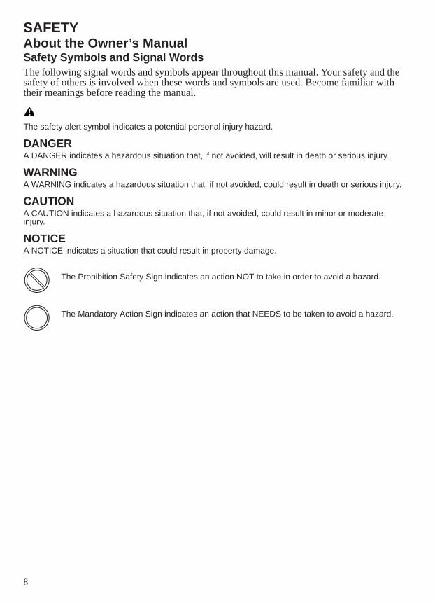
The safety alert symbol indicates a potential personal injury hazard.
DANGERA DANGER indicates a hazardous situation that, if not avoided, will result in death or serious injury.
WARNINGA WARNING indicates a hazardous situation that, if not avoided, could result in death or serious injury.
CAUTIONA CAUTION indicates a hazardous situation that, if not avoided, could result in minor or moderate injury.
NOTICEA NOTICE indicates a situation that could result in property damage.
The Prohibition Safety Sign indicates an action NOT to take in order to avoid a hazard.
The Mandatory Action Sign indicates an action that NEEDS to be taken to avoid a hazard.
9
SAFETYSafe Driving Practices
Improper use of this vehicle can result in serious injury or death to you, your passenger and others. To minimize the risk of injury, read and understand the information contained in this section before operating the vehicle. This section contains safety information specific to the SLINGSHOT vehicle, as well as information about general vehicle safety. Anyone who operates this vehicle must follow these safety precautions.
Operating a SLINGSHOT vehicle has inherent risks.You can minimize those risks, but you can’t eliminate them completely. Even if you’re an experienced 3-wheel vehicle operator or passenger, read all of the safety information in this manual before operating this SLINGSHOT vehicle.• Take a 3-wheel vehicle rider course from the Motorcycle Safety Foundation or another
qualified instructor. The course will help you learn effective turning and braking techniques, traffic strategies and evasive maneuvers, in addition to general safe riding habits. To locate a rider course in your area, contact the Motorcycle Safety Foundation at 1-800-446-9227 or visit their web page at www.msf-usa.org. You may also contact your dealer or the motorcycle regulatory agency in your area of operation.
• Observe all maintenance requirements specified in this manual. For assistance, see the SLINGSHOT Service Manual or your authorized SLINGSHOT dealer.
Design characteristics affect how you should operate the SLINGSHOT vehicle:• The SLINGSHOT is a lightweight 3-wheel vehicle. As such, it will respond differently
than other on-road vehicles in various road and weather conditions. Thoroughly read your owner’s manual and take safety training before operating the SLINGSHOT.
• The SLINGSHOT vehicle is designed for on-road use by one operator with one passenger. The Manufacturing Information label placed on the vehicle contains the Vehicle Identification Number (VIN), Gross Vehicle Weight Rating (GVWR) and Gross Axle Weight Rating (GAWR) information. See page 15. Never exceed the GVWR or the GAWR.
• Driving off-road, driving at excessive speeds, driving with more than one passenger or carrying weight exceeding the maximum weight rating can make handling difficult, which could cause loss of control resulting in injury or death.
• Since the SLINGSHOT has a single, centered rear wheel, “straddling” obstacles with the front tires increases the likelihood that you will encounter the obstacles with the rear tire.
• Read the section in this manual entitled SLINGSHOT Vehicles vs. Other On-Road Vehicles. See page 39.
• During the first 500 miles (800 km) of operation, follow all break-in procedures as outlined in the break-in section beginning on page 40. Failure to do so can result in serious engine damage.
WARNING
10
SAFETYSafe Driving PracticesWear protective apparel to decrease the risk of injury and increase riding comfort.• Always wear a full-face helmet that meets or exceeds established safety standards.
Approved helmets in the USA and Canada bear a U.S. Department of Transportation (DOT) label. Laws in some areas require that riders wear an approved helmet. Head injuries are the leading cause of fatalities in accidents involving vehicles such as the SLINGSHOT vehicle. Statistics prove that an approved helmet is the most effective protection in preventing or reducing head injuries.
• Wear eye protection to protect eyes from wind or airborne particles and objects. Laws in some areas require that you wear eye protection. POLARIS recommends that you wear approved Personal Protective Equipment (PPE) bearing markings such as VESC 8, V-8, Z87.1, or CE. Make sure protective eyewear is kept clean.
• Be prepared for changing weather conditions and dress accordingly.Follow these general safe driving practices:• Always inspect the vehicle before each use to make sure it’s in safe operating condition.
See page 36. Failure to do so may result in vehicle damage or an accident.• Until you’re thoroughly familiar with the SLINGSHOT and all of its controls, practice
driving where there is little or no traffic. Practice driving at a moderate speed on various road surfaces and in different weather conditions. Practice braking in a safe area to become familiar with the feel of the SLINGSHOT brakes before driving in traffic.
• Know your skills and limits, and ride within them.• Allow only licensed, experienced operators to operate your SLINGSHOT, and then only
after they have become familiar with its controls and operation. Make sure all riders read and understand this owner’s manual before riding.
• Do not ride when you’re fatigued or under the influence of alcohol, prescription drugs, over-the-counter drugs or any other drugs. Fatigue, alcohol and drugs can cause drowsiness, loss of coordination and loss of balance. They can also affect your awareness and judgment.
• If your vehicle operates abnormally, cease operation and correct the problem immediately. See the SLINGSHOT Service Manual or an authorized SLINGSHOT dealer.
• Ride defensively, as if you are invisible to other motorists, even in broad daylight. Smaller profile vehicles, such as 2-wheel motorcycles and 3-wheel vehicles such as the SLINGSHOT vehicle may not be immediately seen and recognized by some motorists, which can lead to accidents. Ride where you’re clearly visible to other motorists, and observe their behavior carefully. Always be prepared to take evasive action.
• Be especially cautious at intersections, where accidents often occur.
11
SAFETYSafe Driving PracticesFollow these general safe driving practices:• To prevent loss of control, keep both hands on the steering wheel unless you’re shifting
gears.• Obey the speed limit and adjust your speed and driving technique based on road, weather
and traffic conditions. As you travel faster, the influence of all other conditions increases, which can increase the possibility of losing control.
• Driving while distracted can result in loss of vehicle control, accident and injury. Do not use a mobile phone or other handheld device while operating the vehicle.
• Improper braking may cause loss of control. Apply the brakes gradually when the road is wet, rough or slippery. Allow for a greater braking distance in these conditions. If possible, avoid applying the brakes while making a turn.
• Reduce speed in wet conditions. Pay particular attention if water is beginning to pool on the road. Three-wheeled vehicles behave differently than other vehicles when driving over deep water. Your SLINGSHOT vehicle may hydroplane, which could result in loss of control, if operating speed is too high for the depth of water on the road.
Use of Accessories• Never modify this vehicle through improper installation or use of accessories that are not
SLINGSHOT-approved. Use only genuine SLINGSHOT accessories designed for your SLINGSHOT vehicle.
• Do not install electrical accessories that exceed the capacity of the vehicle’s electrical system. Never install higher wattage light bulbs than those supplied as original equipment. An electrical failure could result and cause hazardous loss of engine power or lights, or damage to the electrical system.
ModificationsModifying this vehicle by removing any equipment or by adding equipment not approved by SLINGSHOT may void your warranty. Such modifications could also make the vehicle unsafe and could result in severe injury to operator or passenger, as well as damage to the vehicle. Some modifications may not be legal in your area of operation. If in doubt, contact your authorized dealer.
Parking the SLINGSHOT VehicleTo help prevent rolling, engage the park brake when the vehicle is parked. See page 29. When leaving the vehicle unattended, turn the engine off and engage the park brake. Remove the ignition key to prevent unauthorized use.
12
SAFETYFuel and Exhaust SafetyAlways heed these fuel safety warnings when refueling or servicing the fuel system. For fuel recommendations and fueling procedures, see page 41.
Gasoline is highly flammable and explosive under certain conditions.• Always exercise extreme caution whenever handling gasoline.• Always turn off the engine before refueling.• Always refuel outdoors or in a well-ventilated area. • Open the fuel cap slowly. Do not overfill the tank. Do not fill the tank neck.• Do not smoke or allow open flames or sparks in or near the area where refueling is performed or
where gasoline is stored.
Gasoline and gasoline vapors are poisonous and can cause severe injury.• Do not swallow gasoline, inhale gasoline vapors, or spill gasoline. If you swallow gasoline, inhale
more than a few breaths of gasoline vapor, or get gasoline in your eyes, see a physician immediately.
• If gasoline spills on your skin or clothing, immediately wash it off with soap and water and change clothing.
Exhaust gases contain carbon monoxide, a colorless, odorless gas that can cause loss of consciousness or death in a short time.• Never start the engine or let it run in an enclosed area.• Never inhale exhaust gases.
WARNING
13
SAFETYSafety MaintenanceCareful periodic maintenance will help keep your vehicle in the safest, most reliable condition. Perform all periodic maintenance at the recommended intervals outlined in the Periodic Maintenance section beginning on page 51. Record maintenance and service in the Maintenance Log beginning on page 97.Inspect, clean, lubricate, adjust and replace parts as necessary. When inspection reveals the need for replacement parts, use genuine SLINGSHOT parts available from your SLINGSHOT dealer.NOTE: Service and adjustments are important for proper vehicle operation. If you're not familiar with
safe service and adjustment procedures, have your authorized dealer perform these operations.
• Before each ride, perform the Pre-Ride Inspections. See page 36.• Always maintain proper tire pressure, tread condition and wheel and tire balance. Inspect
tires regularly and replace worn or damaged tires promptly. Use only SLINGSHOT-approved replacement tires.
• Fasteners must meet original specifications for quality, finish and type to ensure safety. Use only genuine SLINGSHOT replacement parts, and ensure that all fasteners are tightened to the proper torque.
Electromagnetic InterferenceThis vehicle complies with European directive 97/24/EC Chapter 8 requirements, which is equivalent to Canadian ICES-002.
Industry Canada ICES-002(Interference-Causing Equipment Standard)The spark ignition system complies with the Canadian standard ICES-002.Le système d'allumage par étincelle de véhicule est conforme à la norme NMB-002 du Canada.
14
SAFETYGross Vehicle Weight Rating (GVWR)WARNING! Exceeding the gross vehicle weight rating of your vehicle can reduce stability and handling and could cause loss of control. NEVER exceed the GVWR of your vehicle.The maximum load capacity of your vehicle is the maximum weight you may add to your vehicle without exceeding the GVWR. This capacity is determined by calculating the difference between your vehicle’s GVWR and wet weight. Refer to the specifications section beginning on page 84.Refer to the specification section of this manual or the Manufacturing Information/VIN label on the vehicle frame for model-specific information. See page 15.When determining the weight you will be adding to your vehicle, and to ensure you do not exceed the maximum load capacity, include the following:• operator body weight• passenger body weight• weight of all riders’ apparel and items in or on apparel• weight of any non-factory-installed accessories• weight of any additional cargo on the vehicle
Reporting Safety DefectsIf you believe that your vehicle has a defect that could result in a crash or cause injury or death, you should immediately inform the National Highway Traffic Safety Administration (NHTSA) in addition to notifying POLARIS Industries in writing.If NHTSA receives similar complaints, it may open an investigation, and if it finds that a safety defect exists in a group of vehicles, it may order a recall and remedy campaign. However, NHTSA cannot become involved in individual problems between you, your dealer or POLARIS Industries.To contact NHTSA, or obtain other information about motor vehicle safety, you may either call the Vehicle Safety Hotline toll-free at 1-888-327-4236 (TTY: 1-800-424-9153), visit the NHTSA website at www.safercar.gov, or write to:
ADMINISTRATOR, NHTSA1200 New Jersey Avenue, SEWest BuildingWashington, DC 20590
15
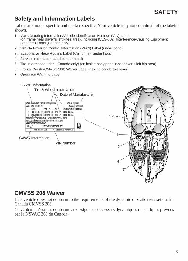
SAFETYSafety and Information LabelsLabels are model-specific and market-specific. Your vehicle may not contain all of the labels shown.1. Manufacturing Information/Vehicle Identification Number (VIN) Label
(on frame near driver’s left knee area), including ICES-002 (Interference-Causing Equipment Standard) Label (Canada only)
2. Vehicle Emission Control Information (VECI) Label (under hood)3. Evaporative Hose Routing Label (California) (under hood)4. Service Information Label (under hood)5. Tire Information Label (Canada only) (on inside body panel near driver’s left hip area)6. Frontal Crash (CMVSS 208) Waiver Label (next to park brake lever)7. Operation Warning Label
CMVSS 208 WaiverThis vehicle does not conform to the requirements of the dynamic or static tests set out in Canada CMVSS 208.Ce véhicule n’est pas conforme aux exigences des essais dynamiques ou statiques prévues par la NSVAC 208 du Canada.
MANUFACTURED BY: POLARIS INDUSTRIES INC. DATE MFD: 02/2014GVWR: 2199 LBS (997 KG) MODEL: T15AASFAAC
GAWR TIRE RIM COLD INFLATION PRESSUREF: 1321 LBS (599 KG) 205/50 R17 93W 17� X 7.0� 32 PSI (221 KPA)R: 878 LBS (398 KG) 265/35 R18 93W 18� X 9.5� 32 PSI (221 KPA)
THIS VEHICLE CONFORMS TO ALL APPLICABLE FEDERAL MOTORVEHICLE SAFETY STANDARDS IN EFFECT ON THE DATE OFMANUFACTURE SHOWN ABOVE
7176966VIN: *57XAASFA5F5000107*
TYPE: MOTORCYCLE ASSEMBLED IN THE U.S.A.
GVWR Information
VIN Number
Tire & Wheel InformationDate of Manufacture
2, 3, 4
5
1
6
GAWR Information
7
16
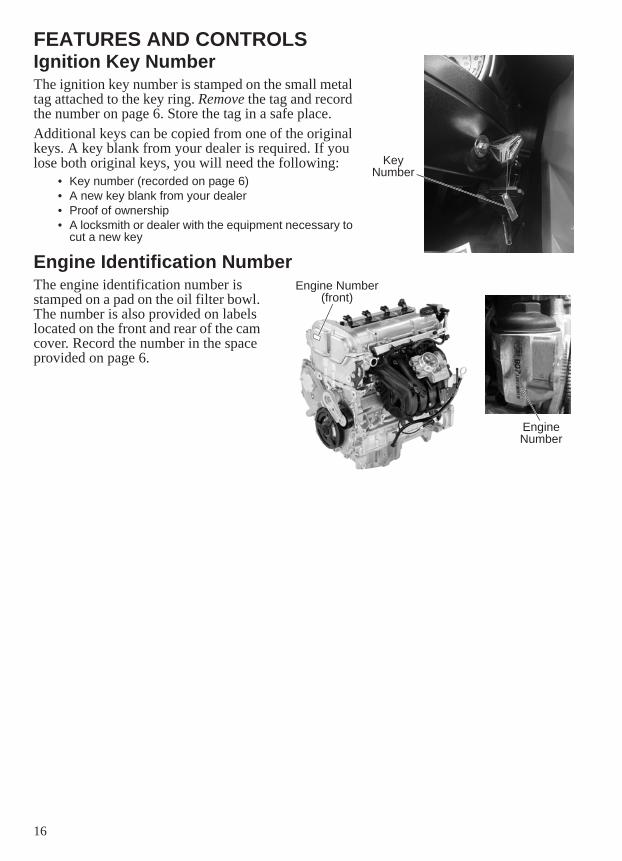
FEATURES AND CONTROLSIgnition Key NumberThe ignition key number is stamped on the small metal tag attached to the key ring. Remove the tag and record the number on page 6. Store the tag in a safe place.Additional keys can be copied from one of the original keys. A key blank from your dealer is required. If you lose both original keys, you will need the following:
• Key number (recorded on page 6)• A new key blank from your dealer• Proof of ownership• A locksmith or dealer with the equipment necessary to
cut a new key
Engine Identification NumberThe engine identification number is stamped on a pad on the oil filter bowl. The number is also provided on labels located on the front and rear of the cam cover. Record the number in the space provided on page 6.
Key Number
Engine Number
Engine Number(front)
17
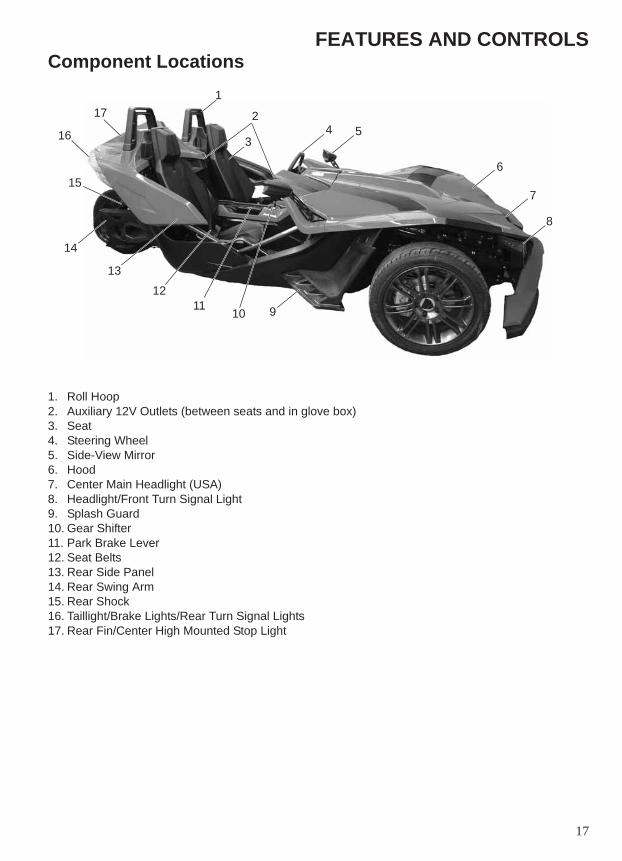
FEATURES AND CONTROLSComponent Locations
1. Roll Hoop2. Auxiliary 12V Outlets (between seats and in glove box)3. Seat4. Steering Wheel5. Side-View Mirror6. Hood7. Center Main Headlight (USA)8. Headlight/Front Turn Signal Light9. Splash Guard10. Gear Shifter11. Park Brake Lever12. Seat Belts13. Rear Side Panel14. Rear Swing Arm15. Rear Shock16. Taillight/Brake Lights/Rear Turn Signal Lights17. Rear Fin/Center High Mounted Stop Light
2
34
1
8
6
91011
12
5
13
15
16
14
17
7
18
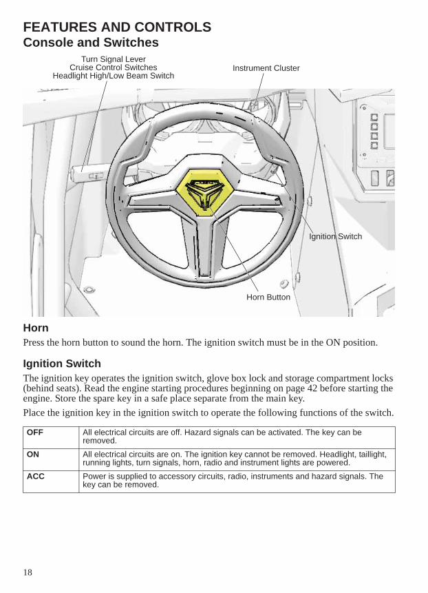
FEATURES AND CONTROLSConsole and Switches
HornPress the horn button to sound the horn. The ignition switch must be in the ON position.
Ignition SwitchThe ignition key operates the ignition switch, glove box lock and storage compartment locks (behind seats). Read the engine starting procedures beginning on page 42 before starting the engine. Store the spare key in a safe place separate from the main key.Place the ignition key in the ignition switch to operate the following functions of the switch.
OFF All electrical circuits are off. Hazard signals can be activated. The key can be removed.
ON All electrical circuits are on. The ignition key cannot be removed. Headlight, taillight, running lights, turn signals, horn, radio and instrument lights are powered.
ACC Power is supplied to accessory circuits, radio, instruments and hazard signals. The key can be removed.
Turn Signal LeverCruise Control Switches
Headlight High/Low Beam Switch
Ignition Switch
Instrument Cluster
Horn Button
19
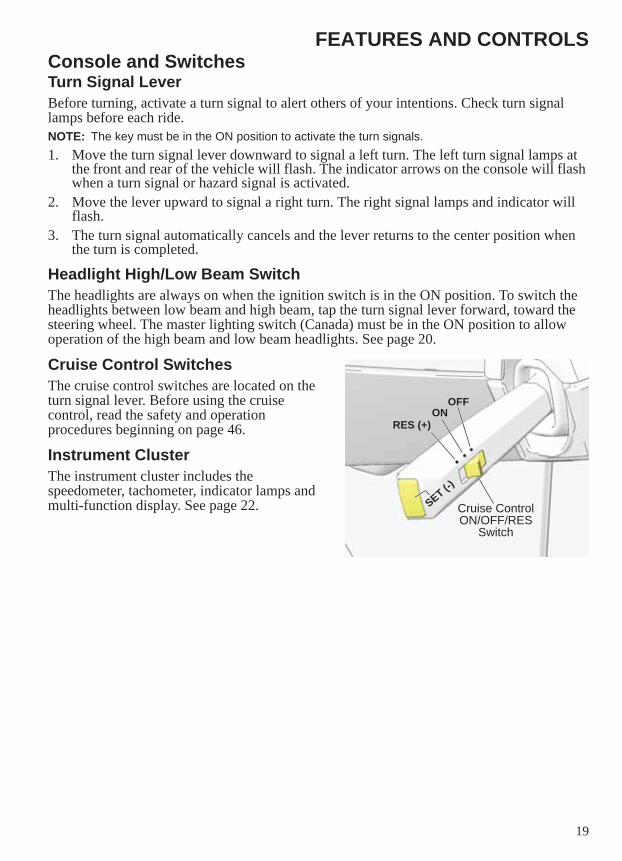
FEATURES AND CONTROLSConsole and SwitchesTurn Signal LeverBefore turning, activate a turn signal to alert others of your intentions. Check turn signal lamps before each ride. NOTE: The key must be in the ON position to activate the turn signals. 1. Move the turn signal lever downward to signal a left turn. The left turn signal lamps at
the front and rear of the vehicle will flash. The indicator arrows on the console will flash when a turn signal or hazard signal is activated.
2. Move the lever upward to signal a right turn. The right signal lamps and indicator will flash.
3. The turn signal automatically cancels and the lever returns to the center position when the turn is completed.
Headlight High/Low Beam SwitchThe headlights are always on when the ignition switch is in the ON position. To switch the headlights between low beam and high beam, tap the turn signal lever forward, toward the steering wheel. The master lighting switch (Canada) must be in the ON position to allow operation of the high beam and low beam headlights. See page 20.
Cruise Control SwitchesThe cruise control switches are located on the turn signal lever. Before using the cruise control, read the safety and operation procedures beginning on page 46.
Instrument ClusterThe instrument cluster includes the speedometer, tachometer, indicator lamps and multi-function display. See page 22. Cruise Control
ON/OFF/RES Switch
RES (+)ON
OFF
SET (-)
20
FEATURES AND CONTROLSConsole and Switches
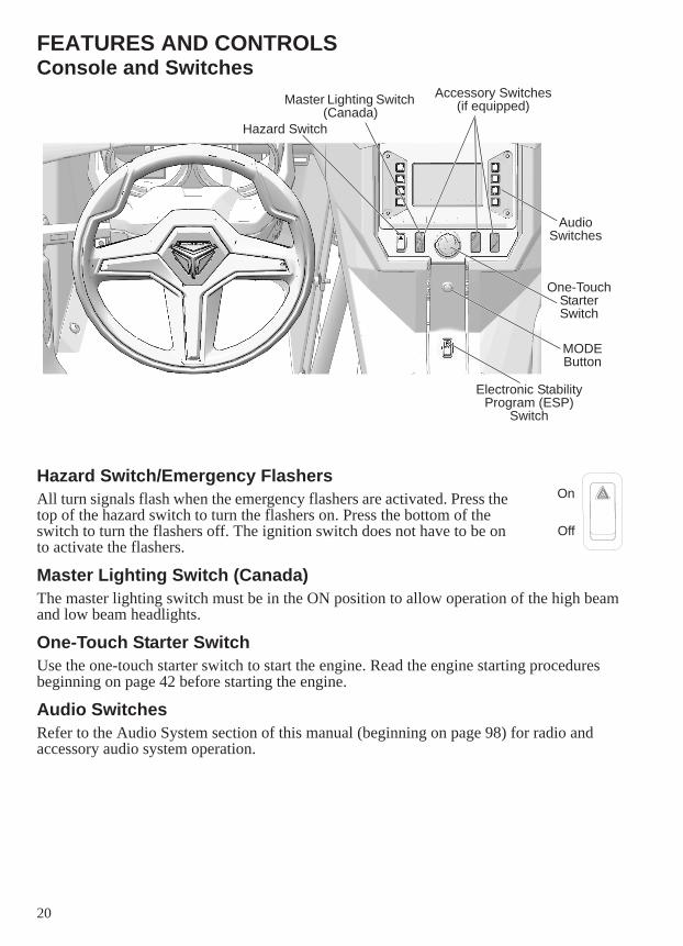
Hazard Switch/Emergency FlashersAll turn signals flash when the emergency flashers are activated. Press the top of the hazard switch to turn the flashers on. Press the bottom of the switch to turn the flashers off. The ignition switch does not have to be on to activate the flashers.
Master Lighting Switch (Canada)The master lighting switch must be in the ON position to allow operation of the high beam and low beam headlights.
One-Touch Starter SwitchUse the one-touch starter switch to start the engine. Read the engine starting procedures beginning on page 42 before starting the engine.
Audio SwitchesRefer to the Audio System section of this manual (beginning on page 98) for radio and accessory audio system operation.
Electronic Stability Program (ESP)
Switch
Hazard Switch
MODE Button
Accessory Switches (if equipped)
One-Touch Starter Switch
Audio Switches
Master Lighting Switch (Canada)
On
Off
21
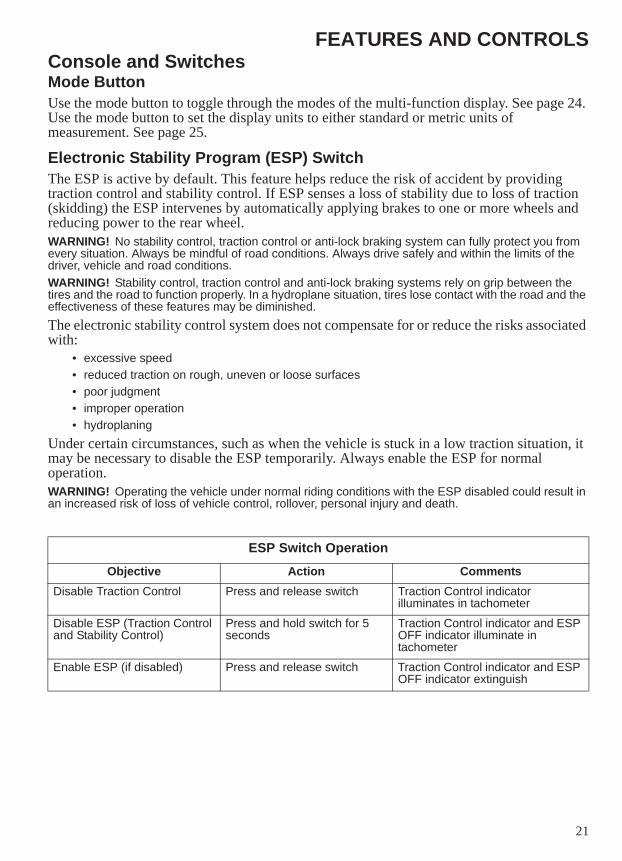
FEATURES AND CONTROLSConsole and SwitchesMode ButtonUse the mode button to toggle through the modes of the multi-function display. See page 24. Use the mode button to set the display units to either standard or metric units of measurement. See page 25.
Electronic Stability Program (ESP) SwitchThe ESP is active by default. This feature helps reduce the risk of accident by providing traction control and stability control. If ESP senses a loss of stability due to loss of traction (skidding) the ESP intervenes by automatically applying brakes to one or more wheels and reducing power to the rear wheel.WARNING! No stability control, traction control or anti-lock braking system can fully protect you from every situation. Always be mindful of road conditions. Always drive safely and within the limits of the driver, vehicle and road conditions. WARNING! Stability control, traction control and anti-lock braking systems rely on grip between the tires and the road to function properly. In a hydroplane situation, tires lose contact with the road and the effectiveness of these features may be diminished.The electronic stability control system does not compensate for or reduce the risks associated with:
• excessive speed• reduced traction on rough, uneven or loose surfaces• poor judgment• improper operation• hydroplaning
Under certain circumstances, such as when the vehicle is stuck in a low traction situation, it may be necessary to disable the ESP temporarily. Always enable the ESP for normal operation.WARNING! Operating the vehicle under normal riding conditions with the ESP disabled could result in an increased risk of loss of vehicle control, rollover, personal injury and death.
ESP Switch OperationObjective Action Comments
Disable Traction Control Press and release switch Traction Control indicator illuminates in tachometer
Disable ESP (Traction Control and Stability Control)
Press and hold switch for 5 seconds
Traction Control indicator and ESP OFF indicator illuminate in tachometer
Enable ESP (if disabled) Press and release switch Traction Control indicator and ESP OFF indicator extinguish
22
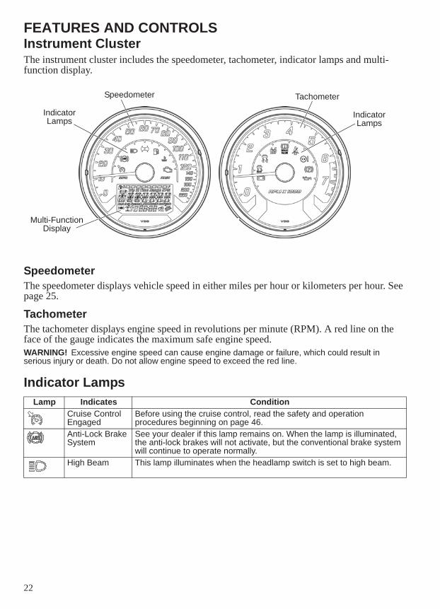
FEATURES AND CONTROLSInstrument ClusterThe instrument cluster includes the speedometer, tachometer, indicator lamps and multi-function display.
SpeedometerThe speedometer displays vehicle speed in either miles per hour or kilometers per hour. See page 25.
TachometerThe tachometer displays engine speed in revolutions per minute (RPM). A red line on the face of the gauge indicates the maximum safe engine speed.WARNING! Excessive engine speed can cause engine damage or failure, which could result in serious injury or death. Do not allow engine speed to exceed the red line.
Indicator LampsLamp Indicates Condition
Cruise Control Engaged
Before using the cruise control, read the safety and operation procedures beginning on page 46.
Anti-Lock Brake System
See your dealer if this lamp remains on. When the lamp is illuminated, the anti-lock brakes will not activate, but the conventional brake system will continue to operate normally.
High Beam This lamp illuminates when the headlamp switch is set to high beam.
Speedometer Tachometer
Indicator Lamps
Multi-Function Display
Indicator Lamps
23
FEATURES AND CONTROLSIndicator Lamps
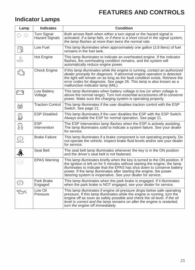
Lamp Indicates ConditionTurn SignalHazard Signals
Both arrows flash when either a turn signal or the hazard signal is activated. If a lamp fails, or if there is a short circuit in the signal system, the lamp flashes at more than twice the normal rate.
Low Fuel This lamp illuminates when approximately one gallon (3.8 liters) of fuel remains in the fuel tank.
Hot Engine This lamp illuminates to indicate an overheated engine. If the indicator flashes, the overheating condition remains, and the system will automatically reduce engine power.
Check Engine If this lamp illuminates while the engine is running, contact an authorized dealer promptly for diagnosis. If abnormal engine operation is detected the light will remain on as long as the fault condition exists. Retrieve the error codes for diagnosis. See page 26. This lamp is also known as a malfunction indicator lamp (MIL).
Low Battery Voltage
This lamp illuminates when battery voltage is low (or when voltage is above the normal range). Turn non-essential accessories off to conserve power. Make sure the charging system is operating properly.
Traction Control This lamp illuminates if the user disables traction control with the ESP Switch. See page 21.
ESP Disabled This lamp illuminates if the user disables the ESP with the ESP Switch. Always enable the ESP for normal operation. See page 21.
ESP Intervention
The ESP Intervention lamp flashes when the ESP is actively assisting. The lamp illuminates solid to indicate a system failure. See your dealer for service.
Brake Failure This lamp illuminates if a brake component is not operating properly. Do not operate the vehicle. Inspect brake fluid levels and/or see your dealer for service.
Seat Belt The seat belt lamp illuminates whenever the key is in the ON position and the driver’s seat belt is not fastened.
EPAS Warning This lamp illuminates briefly when the key is turned to the ON position. If the ignition is left on for 5 minutes without starting the engine, the lamp illuminates to indicate that the EPAS has shut down to conserve battery power. If the lamp illuminates after starting the engine, the power steering system is inoperative. See your dealer for service.
Park Brake Engaged
This lamp illuminates when the park brake is engaged. If it illuminates when the park brake is NOT engaged, see your dealer for service.
Low Oil Pressure
This lamp illuminates if engine oil pressure drops below safe operating pressure. If this lamp illuminates while the engine is running, turn the engine off as soon as safely possible and check the oil level. If the oil level is correct and the lamp remains on after the engine is restarted, turn the engine off immediately.
BRAKE FAILURE
24
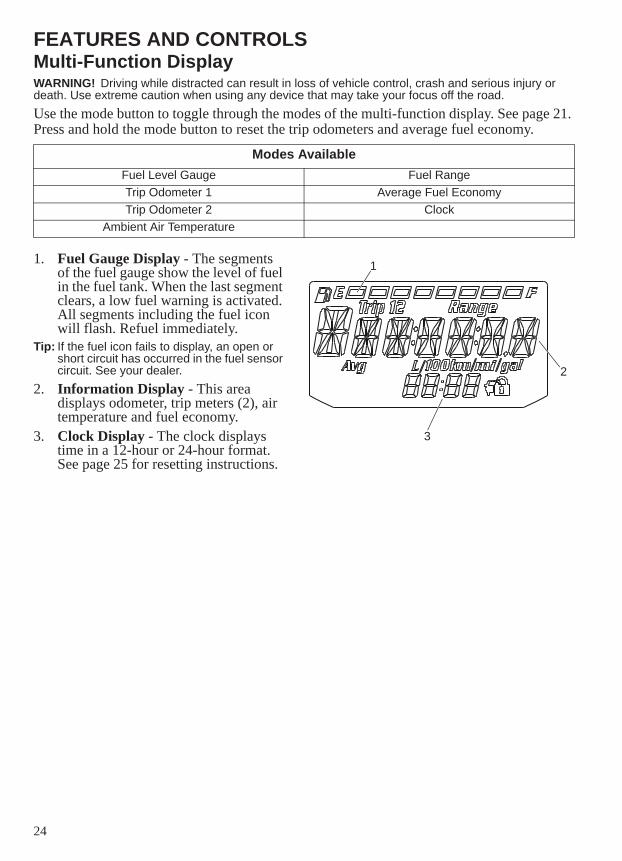
FEATURES AND CONTROLSMulti-Function DisplayWARNING! Driving while distracted can result in loss of vehicle control, crash and serious injury or death. Use extreme caution when using any device that may take your focus off the road.Use the mode button to toggle through the modes of the multi-function display. See page 21. Press and hold the mode button to reset the trip odometers and average fuel economy.
1. Fuel Gauge Display - The segments of the fuel gauge show the level of fuel in the fuel tank. When the last segment clears, a low fuel warning is activated. All segments including the fuel icon will flash. Refuel immediately.
Tip: If the fuel icon fails to display, an open or short circuit has occurred in the fuel sensor circuit. See your dealer.
2. Information Display - This area displays odometer, trip meters (2), air temperature and fuel economy.
3. Clock Display - The clock displays time in a 12-hour or 24-hour format. See page 25 for resetting instructions.
Modes AvailableFuel Level Gauge Fuel RangeTrip Odometer 1 Average Fuel EconomyTrip Odometer 2 Clock
Ambient Air Temperature
1
3
2
25
FEATURES AND CONTROLSMulti-Function DisplayDisplay Units (Standard/Metric)The display can be changed to display either standard or metric units of measurement.NOTE: To exit the set-up mode at any time, wait 10 seconds. The display automatically exits and
returns to the odometer display.
1. Turn the key to the OFF position.2. Press and hold the mode button while turning the key to the ON or ACC position.3. When the display flashes the distance setting, tap the mode button to advance to the
desired setting.4. Press and hold the mode button to save the setting and advance to the next display
option.5. Repeat the procedure to change remaining display settings.
Clock ModeTip: The clock must be reset any time the battery has been disconnected or discharged.1. Turn the key to the ON position. Use the MODE button to toggle to the odometer
display.2. Press and hold the MODE button until the hour segment flashes. Release the button.3. With the segment flashing, tap the MODE button to advance to the desired setting.4. Press and hold the MODE button until the next segment flashes. Release the button.5. Repeat steps 3-4 twice to set the 10-minute and 1-minute segments. After completing the
1-minute segment, step 4 will save the new settings and exit the clock mode.6. Turn the key to the OFF position.
Odometer/Trip Meter ModeThe odometer displays the total distance traveled by the vehicle. Each trip odometer displays distance traveled since the trip odometer was reset. To view the trip odometer, turn the key to the ON position. Use the mode button to toggle to the trip odometer.To reset the trip odometer, toggle to the trip odometer, then press and hold the mode button until the trip odometer resets.
Standard Display Metric DisplayDistance Miles KilometersFuel U.S. Gallons I = Imperial Gallons Liter = LitersTemperature Fahrenheit CelsiusTime 12-Hour Clock 24-Hour Clock
26
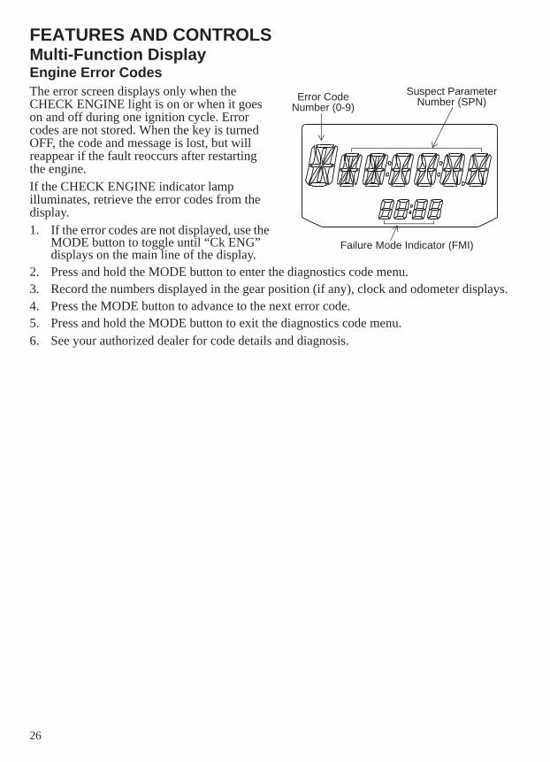
FEATURES AND CONTROLSMulti-Function DisplayEngine Error CodesThe error screen displays only when the CHECK ENGINE light is on or when it goes on and off during one ignition cycle. Error codes are not stored. When the key is turned OFF, the code and message is lost, but will reappear if the fault reoccurs after restarting the engine.If the CHECK ENGINE indicator lamp illuminates, retrieve the error codes from the display.1. If the error codes are not displayed, use the
MODE button to toggle until “Ck ENG” displays on the main line of the display.
2. Press and hold the MODE button to enter the diagnostics code menu.3. Record the numbers displayed in the gear position (if any), clock and odometer displays.4. Press the MODE button to advance to the next error code.5. Press and hold the MODE button to exit the diagnostics code menu.6. See your authorized dealer for code details and diagnosis.
Suspect Parameter Number (SPN)Error Code
Number (0-9)
Failure Mode Indicator (FMI)
27
FEATURES AND CONTROLSStarter Interlock SwitchThe starter interlock switch prevents the electric starter from operating when the clutch is engaged (pedal released). Read the engine starting procedures beginning on page 42 before starting the engine.WARNING! Never start the engine with the transmission in gear and the clutch disengaged unless you are properly seated with helmet on, seat belt secured and brakes applied.
Electronic Power-Assisted Steering (EPAS)Electronic power-assisted steering engages when the ignition key is turned to the ON position. EPAS remains engaged whether the vehicle is moving or idle.To conserve battery power, the EPAS will shut down 5 minutes after the engine is stopped if the key remains in the ON position. The EPAS warning indicator will illuminate to indicate the EPAS has shut down. Turn the key off and on to reset the unit.See page 23 for EPAS warning indicator information.
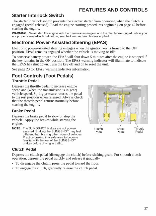
Foot Controls (Foot Pedals)Throttle PedalDepress the throttle pedal to increase engine speed and (when the transmission is in gear) vehicle speed. Spring pressure returns the pedal to the rest position when released. Always check that the throttle pedal returns normally before starting the engine.
Brake PedalDepress the brake pedal to slow or stop the vehicle. Apply the brakes while starting the engine.NOTE: The SLINGSHOT brakes are not power-
assisted. Braking the SLINGSHOT may feel different than braking other types of vehicles. Practice braking in a safe area to become familiar with the feel of the SLINGSHOT brakes before driving in traffic.
Clutch PedalDepress the clutch pedal (disengage the clutch) before shifting gears. For smooth clutch operation, depress the pedal quickly and release it gradually.• To disengage the clutch, press the pedal toward the floor.• To engage the clutch, gradually release the clutch pedal.
Clutch Pedal
Brake Pedal
Throttle Pedal
28
FEATURES AND CONTROLSBrakesAnti-Lock Brake System (ABS)The anti-lock brake system automatically reduces or increases brake pressure as needed to provide optimum braking control, reducing the chance of wheel lock-up during hard braking events or when braking on rough, uneven, slippery or loose surfaces.WARNING! No stability control, traction control or anti-lock braking system can fully protect you from every situation. Always be mindful of road conditions. Always drive safely and within the limits of the driver, vehicle and road conditions. WARNING! Stability control, traction control and anti-lock braking systems rely on grip between the tires and the road to function properly. In a hydroplane situation, tires lose contact with the road and the effectiveness of these features may be diminished.
• The anti-lock brake system cannot be turned off.• When the lamp is illuminated, the anti-lock brakes will not activate, but the conventional
brake system will continue to operate normally. See your dealer promptly for service.• Operating with non-recommended tires or improper tire pressure may reduce the
effectiveness of the anti-lock brake system. Always use the recommended size and type of tires specified for your vehicle. Always maintain the recommended tire pressure.
• The anti-lock brake system will not prevent wheel lockup, loss of traction or loss of control under all conditions. Always adhere to all safe operating practices as recommended.
• It is not unusual to leave tire marks on the road surface during a hard braking event.• The anti-lock brake system does not compensate for or reduce the risks associated with:
• excessive speed• reduced traction on rough, uneven or loose surfaces• poor judgment• improper operation• hydroplaning
29
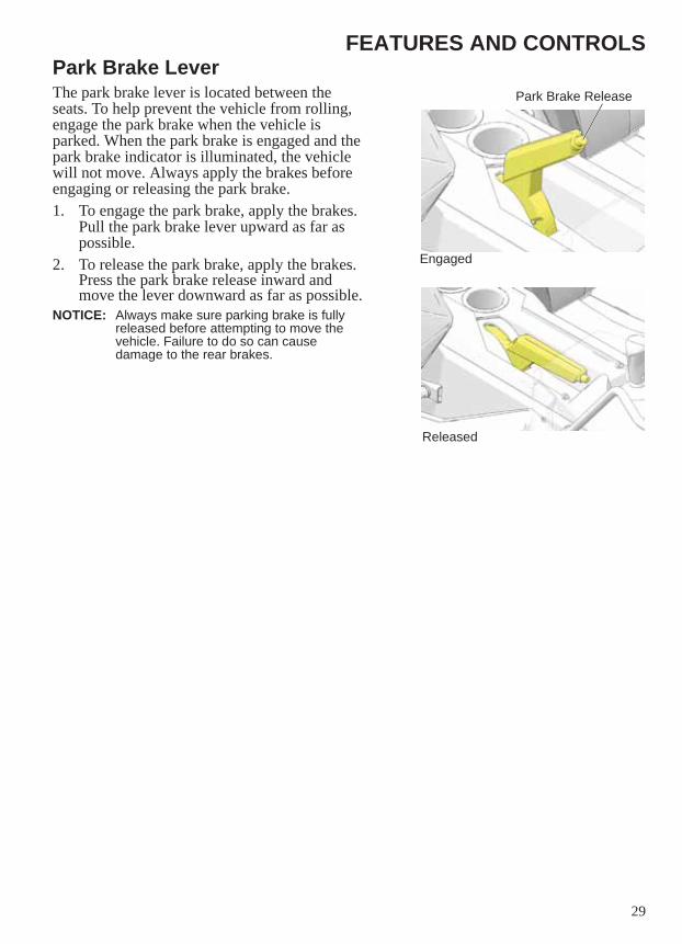
FEATURES AND CONTROLSPark Brake LeverThe park brake lever is located between the seats. To help prevent the vehicle from rolling, engage the park brake when the vehicle is parked. When the park brake is engaged and the park brake indicator is illuminated, the vehicle will not move. Always apply the brakes before engaging or releasing the park brake.1. To engage the park brake, apply the brakes.
Pull the park brake lever upward as far as possible.
2. To release the park brake, apply the brakes. Press the park brake release inward and move the lever downward as far as possible.
NOTICE: Always make sure parking brake is fully released before attempting to move the vehicle. Failure to do so can cause damage to the rear brakes.
Engaged
Released
Park Brake Release
30
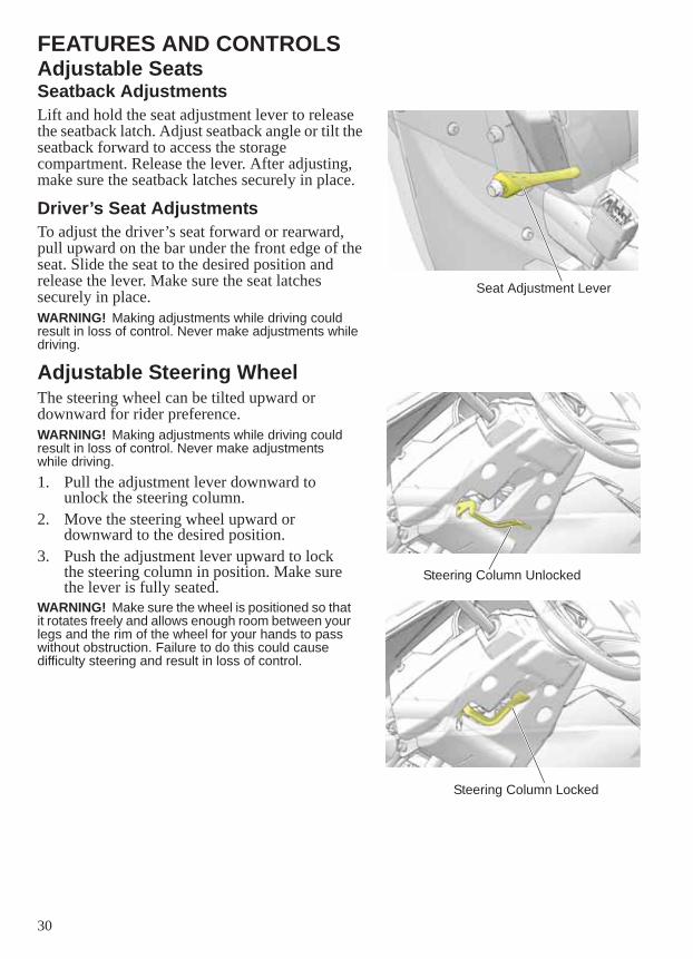
FEATURES AND CONTROLSAdjustable SeatsSeatback AdjustmentsLift and hold the seat adjustment lever to release the seatback latch. Adjust seatback angle or tilt the seatback forward to access the storage compartment. Release the lever. After adjusting, make sure the seatback latches securely in place.
Driver’s Seat AdjustmentsTo adjust the driver’s seat forward or rearward, pull upward on the bar under the front edge of the seat. Slide the seat to the desired position and release the lever. Make sure the seat latches securely in place.WARNING! Making adjustments while driving could result in loss of control. Never make adjustments while driving.
Adjustable Steering WheelThe steering wheel can be tilted upward or downward for rider preference.WARNING! Making adjustments while driving could result in loss of control. Never make adjustments while driving.1. Pull the adjustment lever downward to
unlock the steering column.2. Move the steering wheel upward or
downward to the desired position.3. Push the adjustment lever upward to lock
the steering column in position. Make sure the lever is fully seated.
WARNING! Make sure the wheel is positioned so that it rotates freely and allows enough room between your legs and the rim of the wheel for your hands to pass without obstruction. Failure to do this could cause difficulty steering and result in loss of control.
Seat Adjustment Lever
Steering Column Locked
Steering Column Unlocked
31
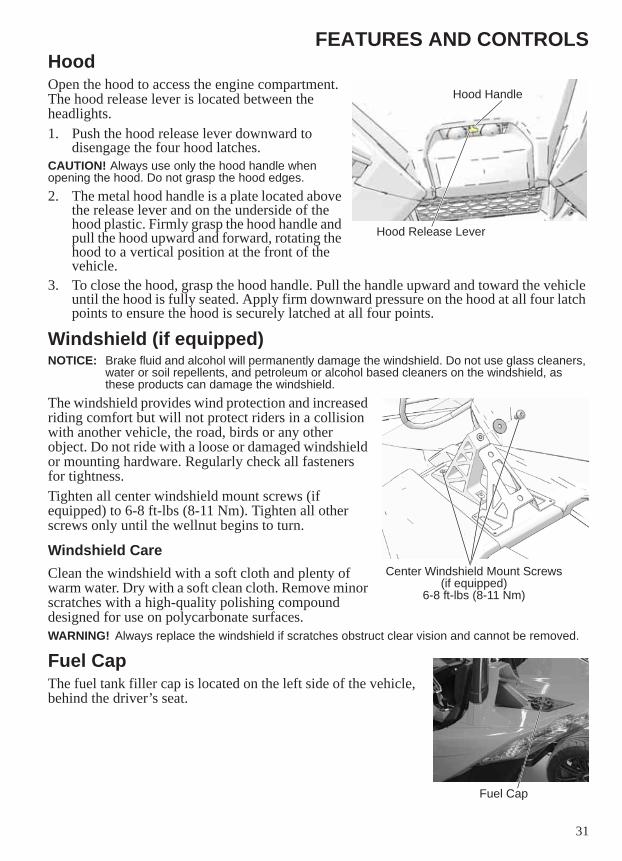
FEATURES AND CONTROLSHoodOpen the hood to access the engine compartment. The hood release lever is located between the headlights.1. Push the hood release lever downward to
disengage the four hood latches.CAUTION! Always use only the hood handle when opening the hood. Do not grasp the hood edges.2. The metal hood handle is a plate located above
the release lever and on the underside of the hood plastic. Firmly grasp the hood handle and pull the hood upward and forward, rotating the hood to a vertical position at the front of the vehicle.
3. To close the hood, grasp the hood handle. Pull the handle upward and toward the vehicle until the hood is fully seated. Apply firm downward pressure on the hood at all four latch points to ensure the hood is securely latched at all four points.
Windshield (if equipped)NOTICE: Brake fluid and alcohol will permanently damage the windshield. Do not use glass cleaners,
water or soil repellents, and petroleum or alcohol based cleaners on the windshield, as these products can damage the windshield.
The windshield provides wind protection and increased riding comfort but will not protect riders in a collision with another vehicle, the road, birds or any other object. Do not ride with a loose or damaged windshield or mounting hardware. Regularly check all fasteners for tightness.Tighten all center windshield mount screws (if equipped) to 6-8 ft-lbs (8-11 Nm). Tighten all other screws only until the wellnut begins to turn.
Windshield CareClean the windshield with a soft cloth and plenty of warm water. Dry with a soft clean cloth. Remove minor scratches with a high-quality polishing compound designed for use on polycarbonate surfaces.WARNING! Always replace the windshield if scratches obstruct clear vision and cannot be removed.
Fuel CapThe fuel tank filler cap is located on the left side of the vehicle, behind the driver’s seat.
Hood Release Lever
Hood Handle
Center Windshield Mount Screws(if equipped)
6-8 ft-lbs (8-11 Nm)
Fuel Cap
32
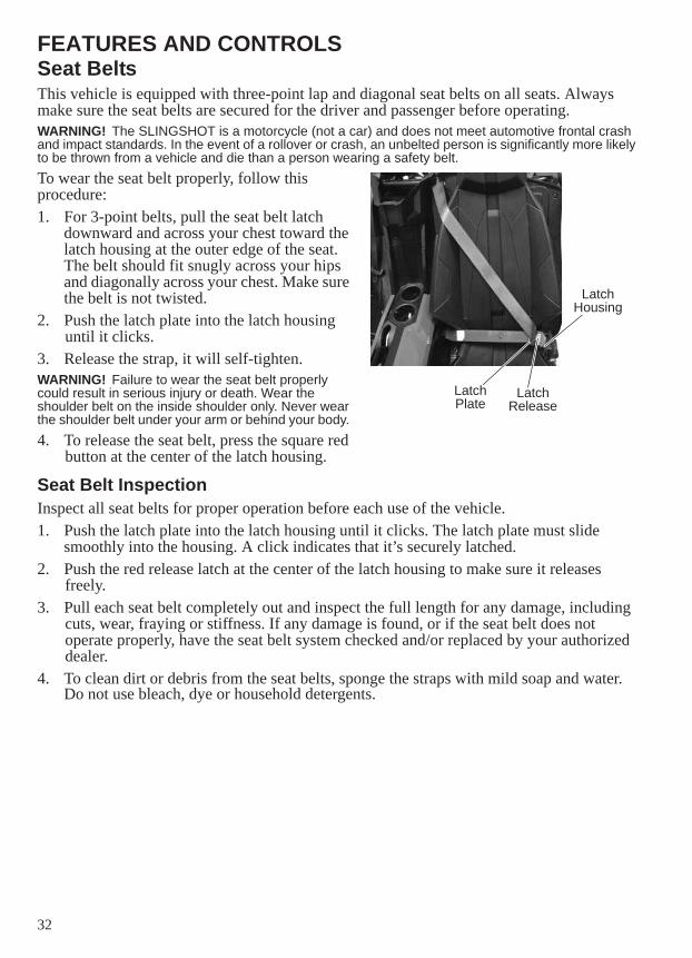
FEATURES AND CONTROLSSeat BeltsThis vehicle is equipped with three-point lap and diagonal seat belts on all seats. Always make sure the seat belts are secured for the driver and passenger before operating.WARNING! The SLINGSHOT is a motorcycle (not a car) and does not meet automotive frontal crash and impact standards. In the event of a rollover or crash, an unbelted person is significantly more likely to be thrown from a vehicle and die than a person wearing a safety belt.To wear the seat belt properly, follow this procedure:1. For 3-point belts, pull the seat belt latch
downward and across your chest toward the latch housing at the outer edge of the seat. The belt should fit snugly across your hips and diagonally across your chest. Make sure the belt is not twisted.
2. Push the latch plate into the latch housing until it clicks.
3. Release the strap, it will self-tighten.WARNING! Failure to wear the seat belt properly could result in serious injury or death. Wear the shoulder belt on the inside shoulder only. Never wear the shoulder belt under your arm or behind your body. 4. To release the seat belt, press the square red
button at the center of the latch housing.
Seat Belt InspectionInspect all seat belts for proper operation before each use of the vehicle.1. Push the latch plate into the latch housing until it clicks. The latch plate must slide
smoothly into the housing. A click indicates that it’s securely latched.2. Push the red release latch at the center of the latch housing to make sure it releases
freely. 3. Pull each seat belt completely out and inspect the full length for any damage, including
cuts, wear, fraying or stiffness. If any damage is found, or if the seat belt does not operate properly, have the seat belt system checked and/or replaced by your authorized dealer.
4. To clean dirt or debris from the seat belts, sponge the straps with mild soap and water. Do not use bleach, dye or household detergents.
Latch Housing
Latch Plate
Latch Release
33
FEATURES AND CONTROLSMirrorsUse the mirrors to assist in traffic maneuvers. Always check and adjust the mirrors before driving the vehicle.
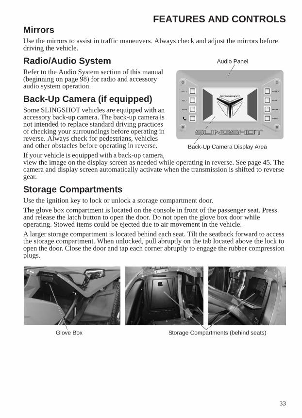
Radio/Audio SystemRefer to the Audio System section of this manual (beginning on page 98) for radio and accessory audio system operation.
Back-Up Camera (if equipped)Some SLINGSHOT vehicles are equipped with an accessory back-up camera. The back-up camera is not intended to replace standard driving practices of checking your surroundings before operating in reverse. Always check for pedestrians, vehicles and other obstacles before operating in reverse.If your vehicle is equipped with a back-up camera, view the image on the display screen as needed while operating in reverse. See page 45. The camera and display screen automatically activate when the transmission is shifted to reverse gear.
Storage CompartmentsUse the ignition key to lock or unlock a storage compartment door. The glove box compartment is located on the console in front of the passenger seat. Press and release the latch button to open the door. Do not open the glove box door while operating. Stowed items could be ejected due to air movement in the vehicle.A larger storage compartment is located behind each seat. Tilt the seatback forward to access the storage compartment. When unlocked, pull abruptly on the tab located above the lock to open the door. Close the door and tap each corner abruptly to engage the rubber compression plugs.
Audio Panel
Back-Up Camera Display Area
Glove Box Storage Compartments (behind seats)
34
FEATURES AND CONTROLSSecurity System (Canada)Your SLINGSHOT vehicle is equipped with a security system for theft and roll-away protection. The security system automatically immobilizes the engine when the ignition is switched off, and enables the engine when the ignition is switched on and a passcode is entered. After the passcode is entered, a slight delay before the starter engages is normal.Change the factory-set passcode to a new passcode of your own choosing and select the desired security setting as soon as possible after receiving delivery of your new SLINGSHOT vehicle. Record your new passcode and keep it in a safe location. Do not place your 4-digit passcode anywhere in the vehicle.NOTE: The park brake must be engaged for the SECURITY menu to be accessible in the gauge.
Changing the PasscodeThe factory-set passcode is 0000. Enter this passcode at step 5 the first time you change the passcode. 1. Unlock the security system. See page 35.2. With the engine off and the park brake engaged, press and release the MODE button
repeatedly until “SECURE” displays in the gauge.3. Press and hold the MODE button until “SETCODE” displays.4. Press and hold the MODE button until “OldCodE” displays.5. Enter your existing passcode using the same process used to unlock the system.6. If the passcode is not correct, “bAd COdE” displays. Re-enter the correct passcode. If
the passcode entered is correct, “NEWCodE” displays. 7. Enter your new passcode using the same process used to unlock the system.8. When “CONFIRM” displays, re-enter the new passcode to confirm.9. If the two entries do not match, “bAd COdE” displays and you’ll be returned to step 7. If
the two entries match, “SUCCESS” displays. The passcode has been changed.10. Record your new passcode and keep it in a safe location. Do not place your 4-digit
passcode anywhere in the vehicle.
35
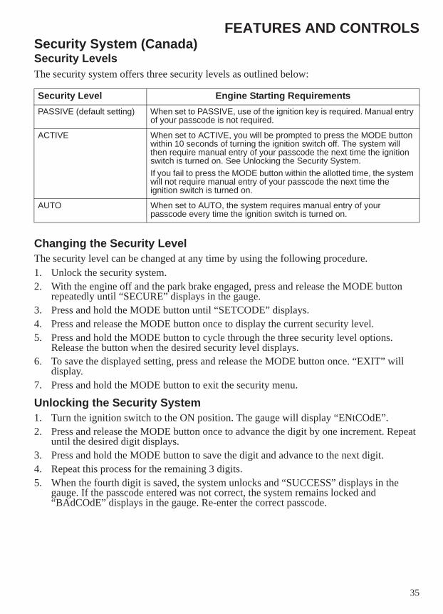
FEATURES AND CONTROLSSecurity System (Canada)Security LevelsThe security system offers three security levels as outlined below:
Changing the Security LevelThe security level can be changed at any time by using the following procedure.1. Unlock the security system.2. With the engine off and the park brake engaged, press and release the MODE button
repeatedly until “SECURE” displays in the gauge.3. Press and hold the MODE button until “SETCODE” displays.4. Press and release the MODE button once to display the current security level.5. Press and hold the MODE button to cycle through the three security level options.
Release the button when the desired security level displays.6. To save the displayed setting, press and release the MODE button once. “EXIT” will
display.7. Press and hold the MODE button to exit the security menu.
Unlocking the Security System1. Turn the ignition switch to the ON position. The gauge will display “ENtCOdE”.2. Press and release the MODE button once to advance the digit by one increment. Repeat
until the desired digit displays.3. Press and hold the MODE button to save the digit and advance to the next digit.4. Repeat this process for the remaining 3 digits.5. When the fourth digit is saved, the system unlocks and “SUCCESS” displays in the
gauge. If the passcode entered was not correct, the system remains locked and “BAdCOdE” displays in the gauge. Re-enter the correct passcode.
Security Level Engine Starting RequirementsPASSIVE (default setting) When set to PASSIVE, use of the ignition key is required. Manual entry
of your passcode is not required.
ACTIVE When set to ACTIVE, you will be prompted to press the MODE button within 10 seconds of turning the ignition switch off. The system will then require manual entry of your passcode the next time the ignition switch is turned on. See Unlocking the Security System.If you fail to press the MODE button within the allotted time, the system will not require manual entry of your passcode the next time the ignition switch is turned on.
AUTO When set to AUTO, the system requires manual entry of your passcode every time the ignition switch is turned on.
36
PRE-RIDE INSPECTIONSTo keep your vehicle in safe operating condition, always perform the recommended pre-ride inspections before each use of the vehicle. This is especially important before making a long trip and when removing the vehicle from storage.WARNING! Failure to perform the recommended pre-ride inspections could result in component failure while riding, which could result in serious injury or death. Always perform the pre-ride inspections before each ride. When inspection reveals the need for adjustment, replacement or repair, perform the service promptly.You must be familiar with all instruments and controls to perform the pre-ride inspections.NOTE: During the pre-ride inspections you may use products that are potentially hazardous, such as
oil or brake fluid. When using any of these products, always follow the instructions and warnings on the product packaging.
When inspections reveal the need for adjustment, replacement or repair:• refer to the maintenance section of this manual• refer to the service manual or• see your authorized dealer
37
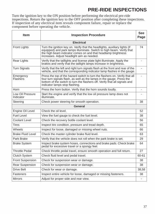
PRE-RIDE INSPECTIONSTurn the ignition key to the ON position before performing the electrical pre-ride inspections. Return the ignition key to the OFF position after completing these inspections. If inspection of any electrical item reveals component failure, repair or replace the component before operating the vehicle.
Item Inspection Procedure See Page
ElectricalFront Lights Turn the ignition key on. Verify that the headlights, auxiliary lights (if
equipped) and park lamps illuminate. Switch to high beam. Verify that the high beam indicator comes on and that headlamp brightness increases. Adjust headlight aim as needed.
74
Rear Lights Verify that the taillights and license plate light illuminate. Apply the brakes and verify that the taillight lamps increase in brightness.
-
Turn Signals Verify that the left and right turn signals flash at the front and rear of the vehicle, and that the corresponding indicator lamp flashes in the gauge.
-
Emergency Flashers
Press the top of the hazard switch to turn the flashers on. Verify that all four turn signals flash, as well as the lamps in the gauge. Press the bottom of the switch to turn the flashers off. Verify that all signals and indicator lamps stop flashing.
-
Horn Press the horn button. Verify that the horn sounds loudly. -Low Oil Pressure Indicator
Start the engine and verify that the low oil pressure lamp does not illuminate.
-
Steering Check power steering for smooth operation. 38General
Engine Oil Level Check the oil level. 52Fuel Level View the fuel gauge to check the fuel level. 38Coolant Level Check the recovery bottle coolant level. 56Tires Inspect tire condition, pressure and tread depth. 65Wheels Inspect for loose, damaged or missing wheel nuts. 66Brake Fluid Level Check the master cylinder brake fluid level. 63Park Brake Verify that the vehicle does not roll when the park brake is set. 29Brake System Inspect brake system hoses, connections and brake pads. Check brake
pedal for excessive travel or a spongy feel.64
Throttle Pedal Check throttle pedal travel, ensure smooth operation and full return. 27Clutch System Check fluid level and pedal travel. 60-61Front Suspension Check for suspension wear or damage. 38Rear Suspension Check for suspension wear or damage. 38Drive Belt Check for wear or damage. 38,58Fasteners Inspect entire vehicle for loose, damaged or missing fasteners. 38Mirrors Adjust for proper side and rear view. -
38
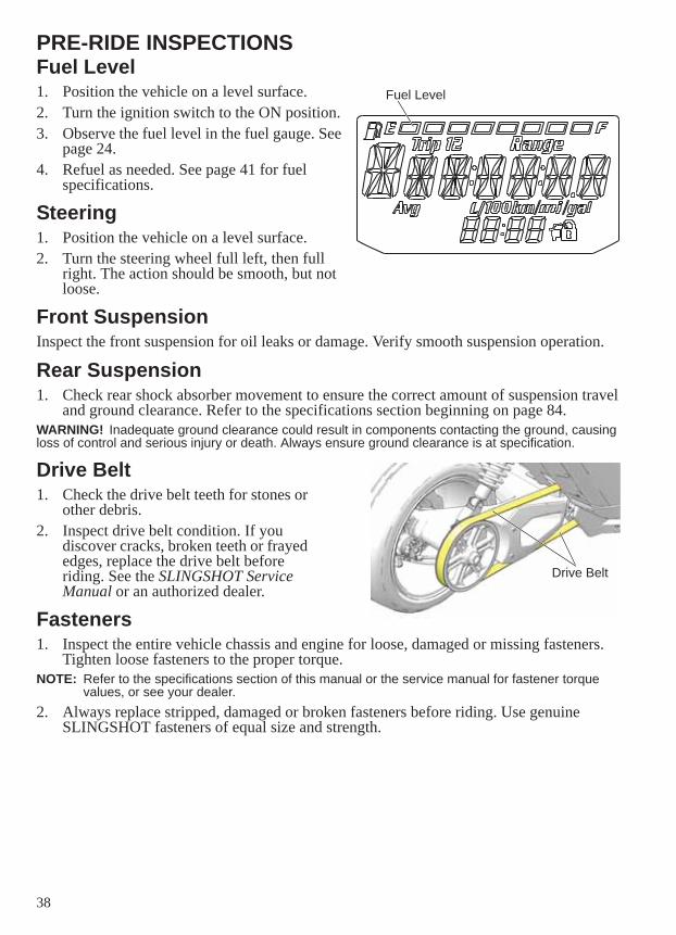
PRE-RIDE INSPECTIONSFuel Level1. Position the vehicle on a level surface.2. Turn the ignition switch to the ON position. 3. Observe the fuel level in the fuel gauge. See
page 24.4. Refuel as needed. See page 41 for fuel
specifications.
Steering1. Position the vehicle on a level surface. 2. Turn the steering wheel full left, then full
right. The action should be smooth, but not loose.
Front SuspensionInspect the front suspension for oil leaks or damage. Verify smooth suspension operation.
Rear Suspension1. Check rear shock absorber movement to ensure the correct amount of suspension travel
and ground clearance. Refer to the specifications section beginning on page 84.WARNING! Inadequate ground clearance could result in components contacting the ground, causing loss of control and serious injury or death. Always ensure ground clearance is at specification.
Drive Belt1. Check the drive belt teeth for stones or
other debris.2. Inspect drive belt condition. If you
discover cracks, broken teeth or frayed edges, replace the drive belt before riding. See the SLINGSHOT Service Manual or an authorized dealer.
Fasteners1. Inspect the entire vehicle chassis and engine for loose, damaged or missing fasteners.
Tighten loose fasteners to the proper torque.NOTE: Refer to the specifications section of this manual or the service manual for fastener torque
values, or see your dealer.2. Always replace stripped, damaged or broken fasteners before riding. Use genuine
SLINGSHOT fasteners of equal size and strength.
Fuel Level
Drive Belt
39
OPERATIONSLINGSHOT Vehicles vs. Other On-Road VehiclesIn the United States, the 3-wheel SLINGSHOT vehicle is an on-road vehicle in the motorcycle class.The SLINGSHOT vehicle handles differently than 2-wheel motorcycles, other 3-wheel vehicles and 4-wheel vehicles. The following information will help you understand the features and characteristics that make operation and handling of the SLINGSHOT vehicle different from the operation and handling of other on-road vehicles.How does a SLINGSHOT differ from a 2-wheel motorcycle?• Low center of gravity• Steering wheel• Foot controls (brake, clutch, accelerator)• Front suspension and steering• Side-by-side operator and passenger seats• Seat belts for both riders• Lighting• One rear drive wheel and two front wheels
The unique handling characteristics of the SLINGSHOT include:• More stability in turns• Vehicle stability at rest• Flat cornering• Turns in direction of wheel• Quick response to steering changes• Like all on-road vehicles, the SLINGSHOT can hydroplane (lose traction) when
encountering a layer of water on the driving surface. Every vehicle has a unique hydroplane speed and response, driven by vehicle weight, tire configuration and tire condition. The SLINGSHOT may hydroplane at lower speeds and react differently to hydroplaning than most motorcycles and cars.
40
OPERATION
NOTICE: Failure to operate the vehicle properly can result in a collision, loss of control, accident or rollover, which may result in serious injury or death. Read and understand all safety warnings outlined in the safety section of this owner’s manual. See pages 7-15.
Break-In PeriodThe break-in period for your vehicle is the first 500 miles (800 km) of operation. During this break-in period, critical engine parts require special wear-in procedures so they seat and mate properly. Read, understand and follow all break-in procedures to ensure the long-term performance and durability of your engine.
Engine and Drivetrain Break-inNOTICE: Failure to properly follow the engine break-in procedures outlined in this manual can result
in serious damage to the engine. Follow all break-in procedures carefully. Avoid full-throttle operation and other conditions that may place an excessive load on the engine during the break-in period.
1. Fill the fuel tank with gasoline. Heed the fuel warnings on page 12.2. Check the oil level. See page 52. Add the recommended oil as needed to maintain the oil
level between the safe and add marks.3. Vary speed. Do not drive at a constant speed, whether fast or slow. Do not drive at
sustained idle. 4. Avoid full-throttle starts and do not drive at full throttle.5. Do not exceed 70 MPH (113 km/h).6. Avoid the use of downshifting to brake or slow the vehicle.7. Avoid making hard stops for the first 200 miles (322 km).8. Perform regular checks on fluid levels, controls and areas outlined on the daily pre-ride
inspection checklist. See page 36.9. Change both the engine oil and filter at 500 miles (800 km).
WARNING
41
OPERATIONFuel RecommendationUse only unleaded gasoline with a 91 pump octane minimum and a maximum ethanol content of 10%. DO NOT USE E-85 GASOLINE OR GASOLINE CONTAINING METHANOL. Using E85 or gasoline/methanol blends can result in poor starting and driveability, and may damage critical fuel system components. NOTICE: Use of fuel other than the recommended fuel could result in voiding of your warranty.
Review the fuel warnings. See page 12. Use only the recommended fuel.1. Insert the fuel nozzle into the fuel tank filler neck. Do not leave the nozzle unattended
while fueling.2. Fill the fuel tank until the pump stops. Do not overfill.WARNING! Fuel expands in the fuel tank. To prevent leaks, make sure the fuel filler cap is properly seated. Do not overfill.NOTICE: Fuel can damage painted surfaces and plastic parts. If gasoline spills on the any part of the
vehicle, immediately rinse it off with water or wipe it dry with a clean cloth.
Priming the Fuel SystemIf the vehicle runs out of fuel, prime the fuel system before attempting to restart the engine.1. Fill the fuel tank.2. Turn the ignition key to the ON position.3. Allow the fuel pump to run until it stops (about 5 seconds).4. Turn the key to the OFF position and wait 10 seconds.5. Repeat steps 2-4 three more times, then start the engine. See page 42.
42
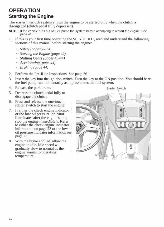
OPERATIONStarting the EngineThe starter interlock system allows the engine to be started only when the clutch is disengaged (clutch pedal fully depressed).NOTE: If the vehicle runs out of fuel, prime the system before attempting to restart the engine. See
page 41.1. If this is your first time operating the SLINGSHOT, read and understand the following
sections of this manual before starting the engine:
2. Perform the Pre-Ride Inspections. See page 36. 3. Insert the key into the ignition switch. Turn the key to the ON position. You should hear
the fuel pump run momentarily as it pressurizes the fuel system.4. Release the park brake.5. Depress the clutch pedal fully to
disengage the clutch.6. Press and release the one-touch
starter switch to start the engine.7. If either the check engine indicator
or the low oil pressure indicator illuminates after the engine starts, stop the engine immediately. Refer to either the check engine indicator information on page 23 or the low oil pressure indicator information on page 23.
8. With the brake applied, allow the engine to idle. Idle speed will gradually slow to normal as the engine warms to operating temperature.
• Safety (pages 7-15)• Starting the Engine (page 42)• Shifting Gears (pages 43-44)• Accelerating (page 44)• Braking (page 44)
Starter Switch
43
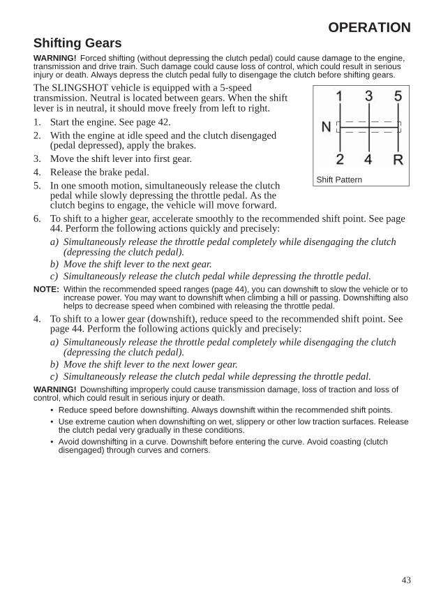
OPERATIONShifting GearsWARNING! Forced shifting (without depressing the clutch pedal) could cause damage to the engine, transmission and drive train. Such damage could cause loss of control, which could result in serious injury or death. Always depress the clutch pedal fully to disengage the clutch before shifting gears.The SLINGSHOT vehicle is equipped with a 5-speed transmission. Neutral is located between gears. When the shift lever is in neutral, it should move freely from left to right.1. Start the engine. See page 42.2. With the engine at idle speed and the clutch disengaged
(pedal depressed), apply the brakes.3. Move the shift lever into first gear.4. Release the brake pedal.5. In one smooth motion, simultaneously release the clutch
pedal while slowly depressing the throttle pedal. As the clutch begins to engage, the vehicle will move forward.
6. To shift to a higher gear, accelerate smoothly to the recommended shift point. See page 44. Perform the following actions quickly and precisely:a) Simultaneously release the throttle pedal completely while disengaging the clutch
(depressing the clutch pedal). b) Move the shift lever to the next gear. c) Simultaneously release the clutch pedal while depressing the throttle pedal.
NOTE: Within the recommended speed ranges (page 44), you can downshift to slow the vehicle or to increase power. You may want to downshift when climbing a hill or passing. Downshifting also helps to decrease speed when combined with releasing the throttle pedal.
4. To shift to a lower gear (downshift), reduce speed to the recommended shift point. See page 44. Perform the following actions quickly and precisely:a) Simultaneously release the throttle pedal completely while disengaging the clutch
(depressing the clutch pedal). b) Move the shift lever to the next lower gear. c) Simultaneously release the clutch pedal while depressing the throttle pedal.
WARNING! Downshifting improperly could cause transmission damage, loss of traction and loss of control, which could result in serious injury or death.
• Reduce speed before downshifting. Always downshift within the recommended shift points.• Use extreme caution when downshifting on wet, slippery or other low traction surfaces. Release
the clutch pedal very gradually in these conditions.• Avoid downshifting in a curve. Downshift before entering the curve. Avoid coasting (clutch
disengaged) through curves and corners.
Shift Pattern
44
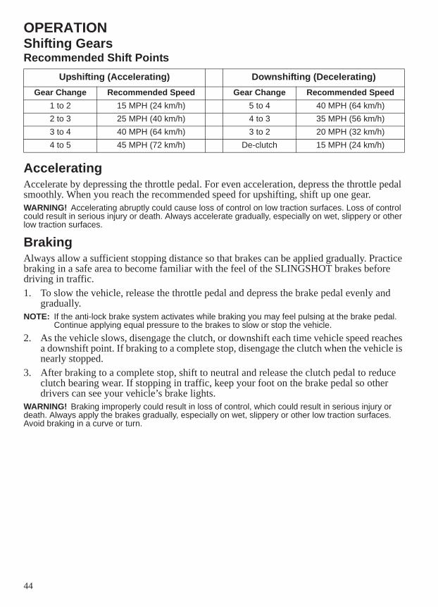
OPERATIONShifting GearsRecommended Shift Points
AcceleratingAccelerate by depressing the throttle pedal. For even acceleration, depress the throttle pedal smoothly. When you reach the recommended speed for upshifting, shift up one gear.WARNING! Accelerating abruptly could cause loss of control on low traction surfaces. Loss of control could result in serious injury or death. Always accelerate gradually, especially on wet, slippery or other low traction surfaces.
BrakingAlways allow a sufficient stopping distance so that brakes can be applied gradually. Practice braking in a safe area to become familiar with the feel of the SLINGSHOT brakes before driving in traffic.1. To slow the vehicle, release the throttle pedal and depress the brake pedal evenly and
gradually.NOTE: If the anti-lock brake system activates while braking you may feel pulsing at the brake pedal.
Continue applying equal pressure to the brakes to slow or stop the vehicle.2. As the vehicle slows, disengage the clutch, or downshift each time vehicle speed reaches
a downshift point. If braking to a complete stop, disengage the clutch when the vehicle is nearly stopped.
3. After braking to a complete stop, shift to neutral and release the clutch pedal to reduce clutch bearing wear. If stopping in traffic, keep your foot on the brake pedal so other drivers can see your vehicle’s brake lights.
WARNING! Braking improperly could result in loss of control, which could result in serious injury or death. Always apply the brakes gradually, especially on wet, slippery or other low traction surfaces. Avoid braking in a curve or turn.
Upshifting (Accelerating) Downshifting (Decelerating)Gear Change Recommended Speed Gear Change Recommended Speed
1 to 2 15 MPH (24 km/h) 5 to 4 40 MPH (64 km/h)2 to 3 25 MPH (40 km/h) 4 to 3 35 MPH (56 km/h)3 to 4 40 MPH (64 km/h) 3 to 2 20 MPH (32 km/h)4 to 5 45 MPH (72 km/h) De-clutch 15 MPH (24 km/h)
45
OPERATIONStopping the EngineBring the vehicle to a complete stop before stopping the engine.WARNING! Stopping the engine with the transmission in gear while the vehicle is moving could cause loss of rear wheel traction or engine and transmission damage, which could cause loss of control and serious injury or death. Always stop the engine after the vehicle is fully stopped and the transmission is in neutral (or clutch is disengaged). If the engine stops unexpectedly while the vehicle is moving, guide the vehicle to a safe location off the road and away from traffic.1. Brake to a complete stop. When nearly stopped, disengage the clutch.NOTE: As the vehicle slows, disengage the clutch, or downshift each time vehicle speed reaches a
downshift point.2. When fully stopped, move the ignition switch to the OFF position. 3. Remove the ignition key.4. Engage the park brake.
Reverse OperationNOTICE: Do not attempt to shift into reverse gear when the vehicle is moving.Follow these precautions when operating in reverse:1. Brake to a complete stop. When nearly stopped, disengage the clutch.2. When fully stopped, shift to neutral.3. Always check for obstacles or people behind the vehicle, and always inspect left and
right fields of vision before operating in reverse. If your vehicle is equipped with a back-up camera, view the display screen for additional assistance as needed while operating in reverse. See page 33.
4. When it’s safe to proceed, shift into reverse gear. 5. Release the brake pedal.6. In one smooth motion, simultaneously release the clutch pedal while slowly depressing
the throttle pedal. As the clutch begins to engage, the vehicle will move rearward.CAUTION! The reverse speed limit feature limits reverse operation to 10 MPH (16 km/h). Do not attempt to exceed this speed. If the engine seems to “cut out”, vehicle speed is exceeding the limit. Reduce throttle and slow down. Exceeding the limit could result in vehicle instability.7. Never apply hard throttle while operating in reverse. 8. Always observe your path of travel and be alert to traffic, pedestrians and obstacles at all
sides of the vehicle while operating in reverse.
46
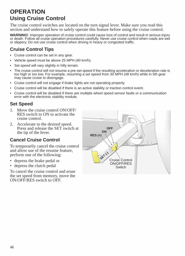
OPERATIONUsing Cruise ControlThe cruise control switches are located on the turn signal lever. Make sure you read this section and understand how to safely operate this feature before using the cruise control.WARNING! Improper operation of cruise control could cause loss of control and result in serious injury or death. Follow all cruise operation procedures carefully. Never use cruise control when roads are wet or slippery. Do not use cruise control when driving in heavy or congested traffic.
Cruise Control Tips• Cruise control can be set in any gear.• Vehicle speed must be above 25 MPH (40 km/h).• Set speed will vary slightly in hilly terrain.• The cruise control will not resume a pre-set speed if the resulting acceleration or deceleration rate is
too high or too low. For example, resuming a set speed from 30 MPH (48 km/h) while in 5th gear may cause cruise to disengage.
• Cruise control will not engage if brake lights are not operating properly.• Cruise control will be disabled if there is an active stability or traction control event.• Cruise control will be disabled if there are multiple wheel speed sensor faults or a communication
error with the electronic stability module.
Set Speed1. Move the cruise control ON/OFF/
RES switch to ON to activate the cruise control.
2. Accelerate to the desired speed. Press and release the SET switch at the tip of the lever.
Cancel Cruise ControlTo temporarily cancel the cruise control and allow use of the resume feature, perform one of the following:• depress the brake pedal or• depress the clutch pedalTo cancel the cruise control and erase the set speed from memory, move the ON/OFF/RES switch to OFF.
Cruise Control ON/OFF/RES
Switch
RES (+)ON
OFF
SET (-)
47
OPERATIONUsing Cruise ControlResume Speed1. Disengage the cruise control by depressing the brake pedal or clutch pedal.NOTE: If you depress the throttle pedal to accelerate, the cruise control will resume the previously set
speed when the pedal is released.2. Move the ON/OFF/RES switch to RES to resume operation at the previously set speed.NOTE: Moving the ON/OFF/RES switch to OFF will erase the set speed from memory and disengage
the cruise control.
Increase Speed SettingMove and release the ON/OFF/RES switch to RES to increase the set speed in approximately one MPH (1-2 km/h) increments. Move and hold the ON/OFF/RES switch in the RES position to accelerate to a new SET speed. The speed will reset when the switch is released or after a maximum acceleration of approximately 10 MPH (16 km/h), whichever comes first.
Reduce Speed SettingPress and release the SET switch to decrease speed in approximately one MPH (1-2 km/h) increments. Press and hold the SET switch to decelerate to a new SET speed (resets when switch is released), or to the minimum cruise speed of 25 MPH (40 km/h).
48
MAINTENANCEProper maintenance assures the highest level of safety, durability and dependability for your SLINGSHOT vehicle.• Have your authorized SLINGSHOT dealer perform the break-in maintenance procedures
when the vehicle’s odometer registers 500 miles (800 km).• See your dealer or perform the recommended periodic maintenance at the intervals
specified in the Periodic Maintenance Chart beginning on page 51.
Break-In MaintenanceHave your dealer perform the break-in maintenance procedures when the vehicle’s odometer registers 500 miles (800 km). Performing the break-in maintenance will help ensure optimum engine performance for the entire service life of the engine. Your dealer will change engine oil, inspect all fluids and serviceable components, ensure that all fasteners are tightened and make other adjustments as needed.
Major MaintenanceFor major repair information, refer to the SLINGSHOT Service Manual. Major repairs typically require technical skills and specially designed tools. Emission system service requires special tools and training and should be performed by your dealer.
49
MAINTENANCESafety During Service Procedures
Failure to follow recommended precautions and procedures could result in severe injury or death. Always heed all safety precautions and follow all operation, inspection and maintenance procedures outlined in this manual.• Improperly installed or adjusted components can result in a system failure. If you do not have the
time, tools and expertise necessary to complete a procedure properly, please see your dealer for service.
• Review the safety-related maintenance information on page 13.• Before beginning any maintenance procedure, read the instructions for the entire procedure.• Always position the vehicle on a firm level surface before performing service.• Wear eye and face protection when using pressurized air.• Never start the engine or let it run in an enclosed area. Engine exhaust fumes are poisonous and
can cause loss of consciousness or death in a short time.• During some procedures you may use potentially hazardous products such as oil or brake fluid.
Always follow the instructions and warnings on the product packaging.
Elevating the Vehicle for ServiceWARNING! Serious injury or death can occur if the vehicle moves or falls while elevated. When elevating is necessary, make sure the vehicle is properly elevated and stable before performing service.Some procedures require elevating the vehicle. DO NOT attempt to elevate your vehicle without proper equipment. If you’re not familiar with using floor jacks or lift mechanisms, see your dealer for service.To elevate the SLINGSHOT vehicle, use automotive-quality floor jacks. Use the floor jacks on a firm, flat surface.Make sure the floor jacks are positioned under the frame rails in the front where the lower control arm mounts to the frame, or in the rear where the frame rails meet.For fluid changes, always make sure the elevated vehicle is level.
WARNING
Bottom View of Lift Points
Side View of Lift Points
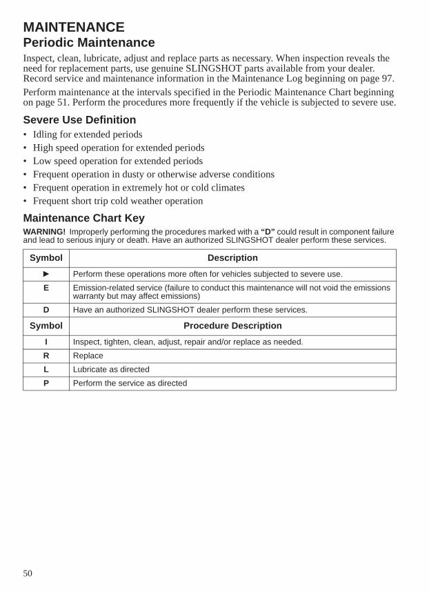
50
MAINTENANCEPeriodic MaintenanceInspect, clean, lubricate, adjust and replace parts as necessary. When inspection reveals the need for replacement parts, use genuine SLINGSHOT parts available from your dealer. Record service and maintenance information in the Maintenance Log beginning on page 97.Perform maintenance at the intervals specified in the Periodic Maintenance Chart beginning on page 51. Perform the procedures more frequently if the vehicle is subjected to severe use.
Severe Use Definition• Idling for extended periods• High speed operation for extended periods• Low speed operation for extended periods• Frequent operation in dusty or otherwise adverse conditions• Frequent operation in extremely hot or cold climates• Frequent short trip cold weather operation
Maintenance Chart KeyWARNING! Improperly performing the procedures marked with a “D” could result in component failure and lead to serious injury or death. Have an authorized SLINGSHOT dealer perform these services.
Symbol DescriptionPerform these operations more often for vehicles subjected to severe use.
E Emission-related service (failure to conduct this maintenance will not void the emissions warranty but may affect emissions)
D Have an authorized SLINGSHOT dealer perform these services.
Symbol Procedure DescriptionI Inspect, tighten, clean, adjust, repair and/or replace as needed.
R Replace
L Lubricate as directed
P Perform the service as directed
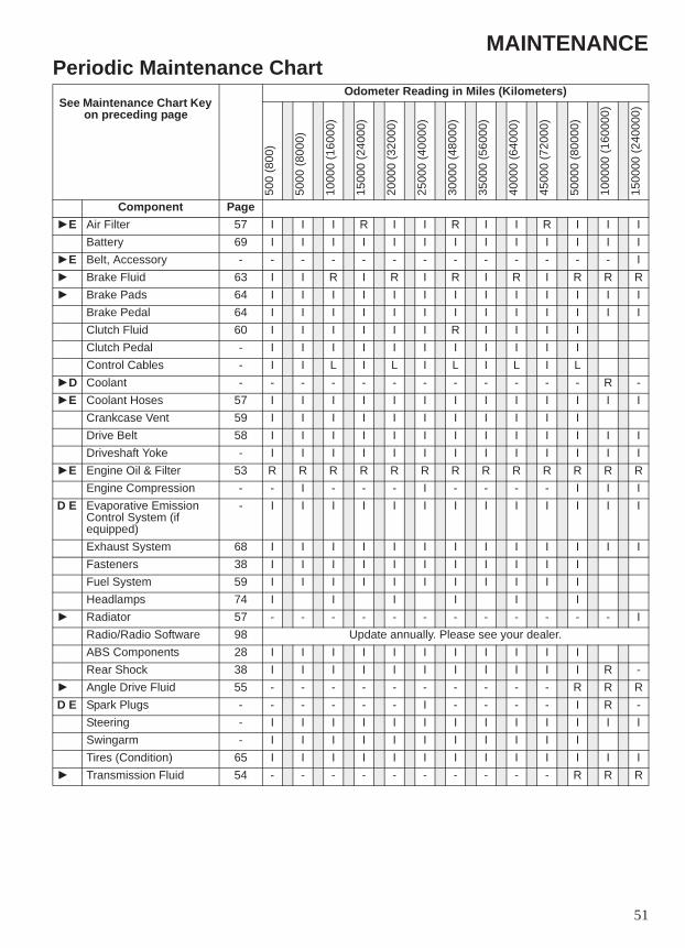
51
MAINTENANCEPeriodic Maintenance ChartSee Maintenance Chart Key
on preceding page
Odometer Reading in Miles (Kilometers)
500
(800
)
5000
(800
0)
1000
0 (1
6000
)
1500
0 (2
4000
)
2000
0 (3
2000
)
2500
0 (4
0000
)
3000
0 (4
8000
)
3500
0 (5
6000
)
4000
0 (6
4000
)
4500
0 (7
2000
)
5000
0 (8
0000
)
1000
00 (1
6000
0)
1500
00 (2
4000
0)
Component PageE Air Filter 57 I I I R I I R I I R I I I
Battery 69 I I I I I I I I I I I I IE Belt, Accessory - - - - - - - - - - - - - I
Brake Fluid 63 I I R I R I R I R I R R RBrake Pads 64 I I I I I I I I I I I I IBrake Pedal 64 I I I I I I I I I I I I IClutch Fluid 60 I I I I I I R I I I IClutch Pedal - I I I I I I I I I I IControl Cables - I I L I L I L I L I L
D Coolant - - - - - - - - - - - - R -E Coolant Hoses 57 I I I I I I I I I I I I I
Crankcase Vent 59 I I I I I I I I I I IDrive Belt 58 I I I I I I I I I I I I IDriveshaft Yoke - I I I I I I I I I I I I I
E Engine Oil & Filter 53 R R R R R R R R R R R R REngine Compression - - I - - - I - - - - I I I
D E Evaporative Emission Control System (if equipped)
- I I I I I I I I I I I I I
Exhaust System 68 I I I I I I I I I I I I IFasteners 38 I I I I I I I I I I IFuel System 59 I I I I I I I I I I IHeadlamps 74 I I I I I IRadiator 57 - - - - - - - - - - - - IRadio/Radio Software 98 Update annually. Please see your dealer.ABS Components 28 I I I I I I I I I I IRear Shock 38 I I I I I I I I I I I R -Angle Drive Fluid 55 - - - - - - - - - - R R R
D E Spark Plugs - - - - - - I - - - - I R -Steering - I I I I I I I I I I I I ISwingarm - I I I I I I I I I I ITires (Condition) 65 I I I I I I I I I I I I ITransmission Fluid 54 - - - - - - - - - - R R R
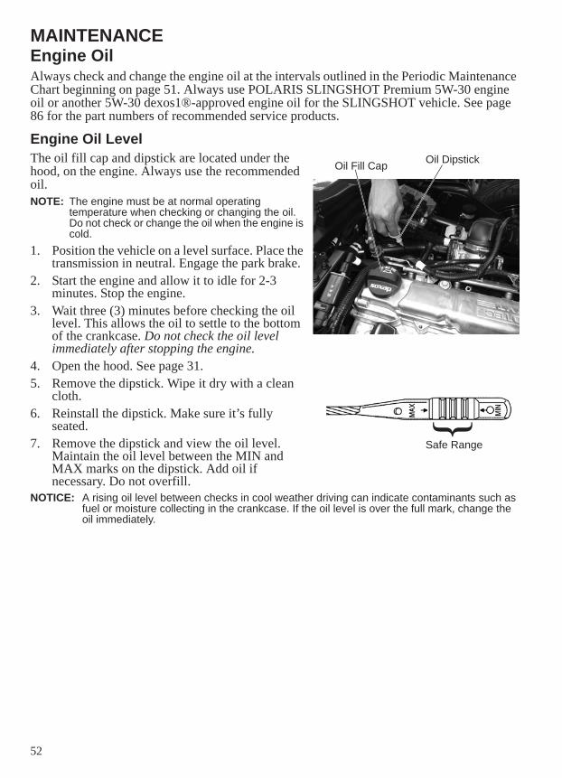
52
MAINTENANCEEngine OilAlways check and change the engine oil at the intervals outlined in the Periodic Maintenance Chart beginning on page 51. Always use POLARIS SLINGSHOT Premium 5W-30 engine oil or another 5W-30 dexos1®-approved engine oil for the SLINGSHOT vehicle. See page 86 for the part numbers of recommended service products.
Engine Oil LevelThe oil fill cap and dipstick are located under the hood, on the engine. Always use the recommended oil.NOTE: The engine must be at normal operating
temperature when checking or changing the oil. Do not check or change the oil when the engine is cold.
1. Position the vehicle on a level surface. Place the transmission in neutral. Engage the park brake.
2. Start the engine and allow it to idle for 2-3 minutes. Stop the engine.
3. Wait three (3) minutes before checking the oil level. This allows the oil to settle to the bottom of the crankcase. Do not check the oil level immediately after stopping the engine.
4. Open the hood. See page 31.5. Remove the dipstick. Wipe it dry with a clean
cloth. 6. Reinstall the dipstick. Make sure it’s fully
seated.7. Remove the dipstick and view the oil level.
Maintain the oil level between the MIN and MAX marks on the dipstick. Add oil if necessary. Do not overfill.
NOTICE: A rising oil level between checks in cool weather driving can indicate contaminants such as fuel or moisture collecting in the crankcase. If the oil level is over the full mark, change the oil immediately.
Oil Fill Cap Oil Dipstick
Safe Range{
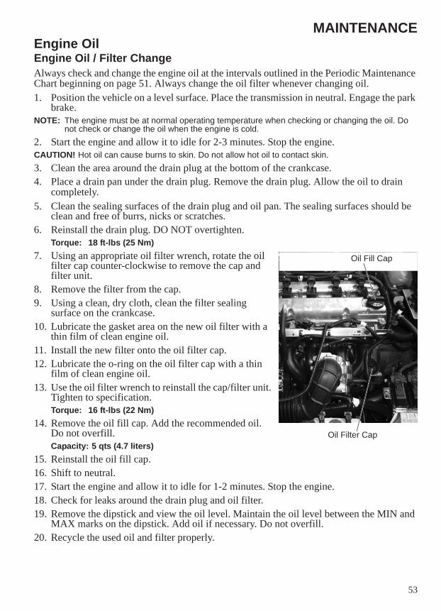
53
MAINTENANCEEngine OilEngine Oil / Filter ChangeAlways check and change the engine oil at the intervals outlined in the Periodic Maintenance Chart beginning on page 51. Always change the oil filter whenever changing oil.1. Position the vehicle on a level surface. Place the transmission in neutral. Engage the park
brake.NOTE: The engine must be at normal operating temperature when checking or changing the oil. Do
not check or change the oil when the engine is cold.2. Start the engine and allow it to idle for 2-3 minutes. Stop the engine.CAUTION! Hot oil can cause burns to skin. Do not allow hot oil to contact skin.3. Clean the area around the drain plug at the bottom of the crankcase.4. Place a drain pan under the drain plug. Remove the drain plug. Allow the oil to drain
completely.5. Clean the sealing surfaces of the drain plug and oil pan. The sealing surfaces should be
clean and free of burrs, nicks or scratches.6. Reinstall the drain plug. DO NOT overtighten.
Torque: 18 ft-lbs (25 Nm)7. Using an appropriate oil filter wrench, rotate the oil
filter cap counter-clockwise to remove the cap and filter unit.
8. Remove the filter from the cap.9. Using a clean, dry cloth, clean the filter sealing
surface on the crankcase.10. Lubricate the gasket area on the new oil filter with a
thin film of clean engine oil. 11. Install the new filter onto the oil filter cap.12. Lubricate the o-ring on the oil filter cap with a thin
film of clean engine oil.13. Use the oil filter wrench to reinstall the cap/filter unit.
Tighten to specification.Torque: 16 ft-lbs (22 Nm)
14. Remove the oil fill cap. Add the recommended oil. Do not overfill.Capacity: 5 qts (4.7 liters)
15. Reinstall the oil fill cap.16. Shift to neutral.17. Start the engine and allow it to idle for 1-2 minutes. Stop the engine.18. Check for leaks around the drain plug and oil filter. 19. Remove the dipstick and view the oil level. Maintain the oil level between the MIN and
MAX marks on the dipstick. Add oil if necessary. Do not overfill.20. Recycle the used oil and filter properly.
Oil Filter Cap
Oil Fill Cap
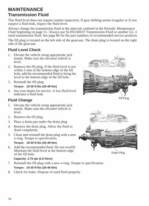
54
MAINTENANCETransmission FluidThis fluid level does not require routine inspection. If gear shifting seems irregular or if you suspect a fluid leak, inspect the fluid level.Always change the transmission fluid at the intervals outlined in the Periodic Maintenance Chart beginning on page 51. Always use SLINGSHOT Transmission Fluid or another GL-3 rated transmission fluid. See page 86 for the part numbers of recommended service products.The fill plug is located on the left side of the gearcase. The drain plug is located on the right side of the gearcase.
Fluid Level Check1. Elevate the vehicle using appropriate jack
stands. Make sure the elevated vehicle is level.
2. Remove the fill plug. If the fluid level is not within 5 mm of the bottom edge of the fill hole, add the recommended fluid to bring the level to the bottom edge of the fill hole.
3. Reinstall the fill plug.Torque: 19-35 ft-lbs (26-48 Nm)
4. See your dealer for service. A low fluid level indicates a fluid leak.
Fluid Change1. Elevate the vehicle using appropriate jack
stands. Make sure the elevated vehicle is level.
2. Remove the fill plug.3. Place a drain pan under the drain plug.4. Remove the drain plug. Allow the fluid to
drain completely.5. Clean and reinstall the drain plug with a new
o-ring. Torque to specification.Torque: 19-35 ft-lbs (26-48 Nm)
6. Add the recommended fluid. Do not overfill. Maintain the fluid level at the bottom edge of the fill hole.Capacity: 2.75 qts (2.6 liters)
7. Reinstall the fill plug with a new o-ring. Torque to specification.Torque: 19-35 ft-lbs (26-48 Nm)
8. Check for leaks. Dispose of used fluid properly.
Drain Plug
Fill Plug
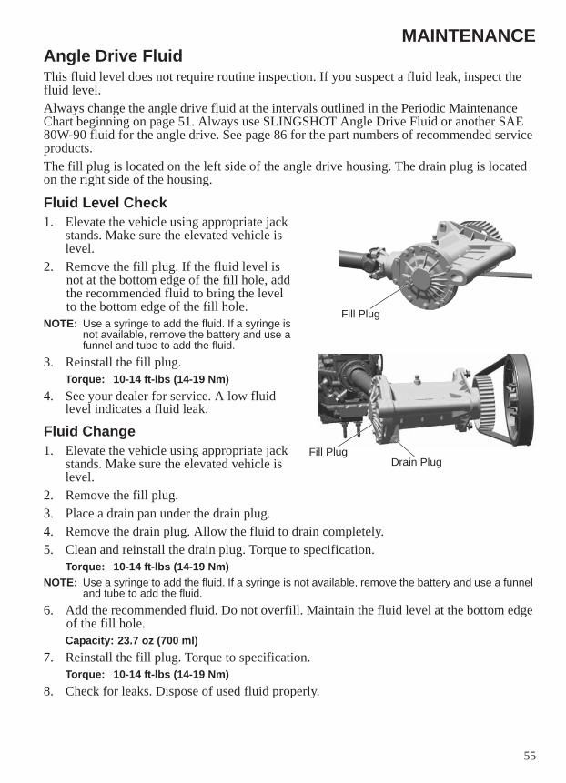
55
MAINTENANCEAngle Drive FluidThis fluid level does not require routine inspection. If you suspect a fluid leak, inspect the fluid level.Always change the angle drive fluid at the intervals outlined in the Periodic Maintenance Chart beginning on page 51. Always use SLINGSHOT Angle Drive Fluid or another SAE 80W-90 fluid for the angle drive. See page 86 for the part numbers of recommended service products.The fill plug is located on the left side of the angle drive housing. The drain plug is located on the right side of the housing.
Fluid Level Check1. Elevate the vehicle using appropriate jack
stands. Make sure the elevated vehicle is level.
2. Remove the fill plug. If the fluid level is not at the bottom edge of the fill hole, add the recommended fluid to bring the level to the bottom edge of the fill hole.
NOTE: Use a syringe to add the fluid. If a syringe is not available, remove the battery and use a funnel and tube to add the fluid.
3. Reinstall the fill plug.Torque: 10-14 ft-lbs (14-19 Nm)
4. See your dealer for service. A low fluid level indicates a fluid leak.
Fluid Change1. Elevate the vehicle using appropriate jack
stands. Make sure the elevated vehicle is level.
2. Remove the fill plug.3. Place a drain pan under the drain plug.4. Remove the drain plug. Allow the fluid to drain completely.5. Clean and reinstall the drain plug. Torque to specification.
Torque: 10-14 ft-lbs (14-19 Nm)NOTE: Use a syringe to add the fluid. If a syringe is not available, remove the battery and use a funnel
and tube to add the fluid.6. Add the recommended fluid. Do not overfill. Maintain the fluid level at the bottom edge
of the fill hole.Capacity: 23.7 oz (700 ml)
7. Reinstall the fill plug. Torque to specification.Torque: 10-14 ft-lbs (14-19 Nm)
8. Check for leaks. Dispose of used fluid properly.
Drain Plug
Fill Plug
Fill Plug
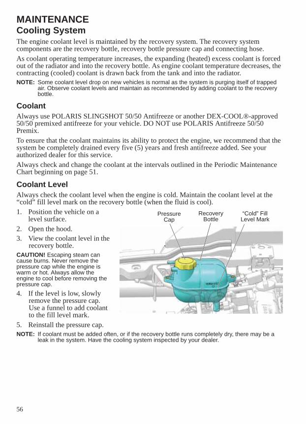
56
MAINTENANCECooling SystemThe engine coolant level is maintained by the recovery system. The recovery system components are the recovery bottle, recovery bottle pressure cap and connecting hose.As coolant operating temperature increases, the expanding (heated) excess coolant is forced out of the radiator and into the recovery bottle. As engine coolant temperature decreases, the contracting (cooled) coolant is drawn back from the tank and into the radiator.NOTE: Some coolant level drop on new vehicles is normal as the system is purging itself of trapped
air. Observe coolant levels and maintain as recommended by adding coolant to the recovery bottle.
CoolantAlways use POLARIS SLINGSHOT 50/50 Antifreeze or another DEX-COOL®-approved 50/50 premixed antifreeze for your vehicle. DO NOT use POLARIS Antifreeze 50/50 Premix.To ensure that the coolant maintains its ability to protect the engine, we recommend that the system be completely drained every five (5) years and fresh antifreeze added. See your authorized dealer for this service.Always check and change the coolant at the intervals outlined in the Periodic Maintenance Chart beginning on page 51.
Coolant LevelAlways check the coolant level when the engine is cold. Maintain the coolant level at the “cold” fill level mark on the recovery bottle (when the fluid is cool).1. Position the vehicle on a
level surface.2. Open the hood. 3. View the coolant level in the
recovery bottle.CAUTION! Escaping steam can cause burns. Never remove the pressure cap while the engine is warm or hot. Always allow the engine to cool before removing the pressure cap.4. If the level is low, slowly
remove the pressure cap. Use a funnel to add coolant to the fill level mark.
5. Reinstall the pressure cap.NOTE: If coolant must be added often, or if the recovery bottle runs completely dry, there may be a
leak in the system. Have the cooling system inspected by your dealer.
Pressure Cap
Recovery Bottle
“Cold” Fill Level Mark
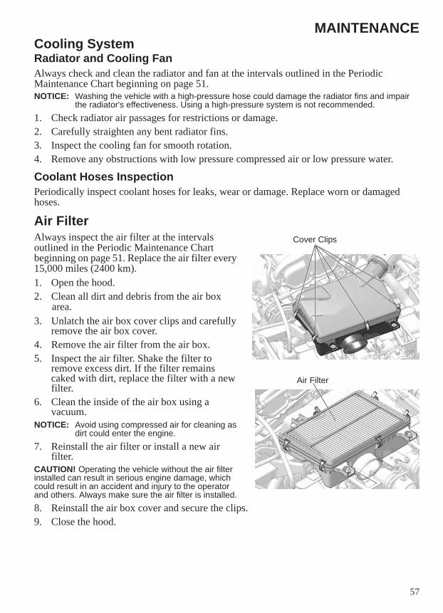
57
MAINTENANCECooling SystemRadiator and Cooling FanAlways check and clean the radiator and fan at the intervals outlined in the Periodic Maintenance Chart beginning on page 51. NOTICE: Washing the vehicle with a high-pressure hose could damage the radiator fins and impair
the radiator's effectiveness. Using a high-pressure system is not recommended.1. Check radiator air passages for restrictions or damage.2. Carefully straighten any bent radiator fins.3. Inspect the cooling fan for smooth rotation.4. Remove any obstructions with low pressure compressed air or low pressure water.
Coolant Hoses InspectionPeriodically inspect coolant hoses for leaks, wear or damage. Replace worn or damaged hoses.
Air FilterAlways inspect the air filter at the intervals outlined in the Periodic Maintenance Chart beginning on page 51. Replace the air filter every 15,000 miles (2400 km).1. Open the hood.2. Clean all dirt and debris from the air box
area.3. Unlatch the air box cover clips and carefully
remove the air box cover.4. Remove the air filter from the air box. 5. Inspect the air filter. Shake the filter to
remove excess dirt. If the filter remains caked with dirt, replace the filter with a new filter.
6. Clean the inside of the air box using a vacuum.
NOTICE: Avoid using compressed air for cleaning as dirt could enter the engine.
7. Reinstall the air filter or install a new air filter.
CAUTION! Operating the vehicle without the air filter installed can result in serious engine damage, which could result in an accident and injury to the operator and others. Always make sure the air filter is installed.8. Reinstall the air box cover and secure the clips.9. Close the hood.
Cover Clips
Air Filter
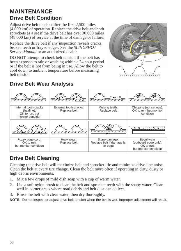
58
MAINTENANCEDrive Belt ConditionAdjust drive belt tension after the first 2,500 miles (4,000 km) of operation. Replace the drive belt and both sprockets as a set if the drive belt has over 30,000 miles (48,000 km) of service at the time of damage or failure.Replace the drive belt if any inspection reveals cracks, broken teeth or frayed edges. See the SLINGSHOT Service Manual or an authorized dealer. DO NOT attempt to check belt tension if the belt has been exposed to rain or washing within a 24 hour period or if the belt is hot from being in use. Allow the belt to cool down to ambient temperature before measuring belt tension.
Drive Belt Wear Analysis
Drive Belt CleaningCleaning the drive belt will maximize belt and sprocket life and minimize drive line noise. Clean the belt at every tire change. Clean the belt more often if operating in dirty, dusty or high debris environments.1. Mix a few drops of mild dish soap with a cup of warm water.2. Use a soft nylon brush to clean the belt and sprocket teeth with the soapy water. Clean
well in corner areas where road debris and belt dust can collect.3. Rinse the belt with clear water, then dry thoroughly.NOTE: Do not inspect or adjust drive belt tension when the belt is wet. Improper adjustment will result.
Internal tooth cracks(hairline):
OK to run, butmonitor condition
External tooth cracks:Replace belt
Missing teeth:Replace belt
Chipping (not serious):OK to run, but monitor
condition
Fuzzy edge cord:OK to run,
but monitor condition
Hook wear:Replace belt
Stone damage:Replace belt if damage is
on edge
Bevel wear(outboard edge only):
OK to run,but monitor condition
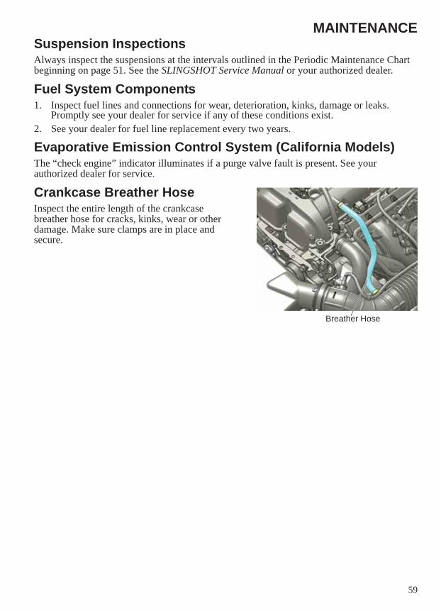
59
MAINTENANCESuspension InspectionsAlways inspect the suspensions at the intervals outlined in the Periodic Maintenance Chart beginning on page 51. See the SLINGSHOT Service Manual or your authorized dealer.
Fuel System Components1. Inspect fuel lines and connections for wear, deterioration, kinks, damage or leaks.
Promptly see your dealer for service if any of these conditions exist.2. See your dealer for fuel line replacement every two years.
Evaporative Emission Control System (California Models)The “check engine” indicator illuminates if a purge valve fault is present. See your authorized dealer for service.
Crankcase Breather HoseInspect the entire length of the crankcase breather hose for cracks, kinks, wear or other damage. Make sure clamps are in place and secure.
Breather Hose
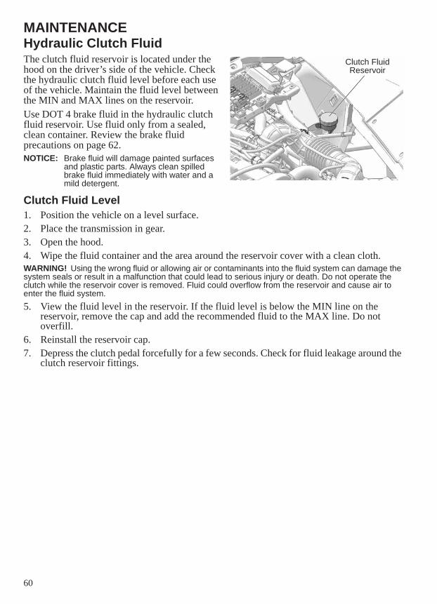
60
MAINTENANCEHydraulic Clutch FluidThe clutch fluid reservoir is located under the hood on the driver’s side of the vehicle. Check the hydraulic clutch fluid level before each use of the vehicle. Maintain the fluid level between the MIN and MAX lines on the reservoir.Use DOT 4 brake fluid in the hydraulic clutch fluid reservoir. Use fluid only from a sealed, clean container. Review the brake fluid precautions on page 62.NOTICE: Brake fluid will damage painted surfaces
and plastic parts. Always clean spilled brake fluid immediately with water and a mild detergent.
Clutch Fluid Level1. Position the vehicle on a level surface.2. Place the transmission in gear.3. Open the hood.4. Wipe the fluid container and the area around the reservoir cover with a clean cloth.WARNING! Using the wrong fluid or allowing air or contaminants into the fluid system can damage the system seals or result in a malfunction that could lead to serious injury or death. Do not operate the clutch while the reservoir cover is removed. Fluid could overflow from the reservoir and cause air to enter the fluid system. 5. View the fluid level in the reservoir. If the fluid level is below the MIN line on the
reservoir, remove the cap and add the recommended fluid to the MAX line. Do not overfill.
6. Reinstall the reservoir cap.7. Depress the clutch pedal forcefully for a few seconds. Check for fluid leakage around the
clutch reservoir fittings.
Clutch Fluid Reservoir
61
MAINTENANCEHydraulic Clutch FluidClutch Fluid ChangeAlways change fluid if the fluid becomes contaminated, if the fluid condition is questionable, or if the type and brand of the fluid in the reservoir are unknown.1. Position the vehicle on a level surface.2. Place the transmission in gear.3. Open the hood.4. Wipe the fluid container and the area around the reservoir cover with a clean cloth.WARNING! Using the wrong fluid or allowing air or contaminants into the fluid system can damage the system seals or result in a malfunction that could lead to serious injury or death. Do not operate the clutch while the reservoir cover is removed. Fluid could overflow from the reservoir and cause air to enter the fluid system. 5. Using a syringe or vacuum-type tool, remove the old fluid from the fluid reservoir.6. Refill the reservoir to the MAX line with the recommended fluid. Do not overfill.7. Reinstall the reservoir cap.8. Depress the clutch pedal forcefully for a few seconds. Check for fluid leakage around the
clutch reservoir fittings.
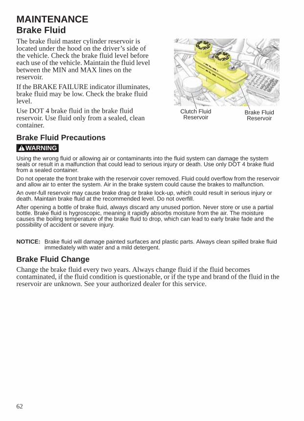
62
MAINTENANCEBrake FluidThe brake fluid master cylinder reservoir is located under the hood on the driver’s side of the vehicle. Check the brake fluid level before each use of the vehicle. Maintain the fluid level between the MIN and MAX lines on the reservoir.If the BRAKE FAILURE indicator illuminates, brake fluid may be low. Check the brake fluid level.Use DOT 4 brake fluid in the brake fluid reservoir. Use fluid only from a sealed, clean container.
Brake Fluid Precautions
Using the wrong fluid or allowing air or contaminants into the fluid system can damage the system seals or result in a malfunction that could lead to serious injury or death. Use only DOT 4 brake fluid from a sealed container.Do not operate the front brake with the reservoir cover removed. Fluid could overflow from the reservoir and allow air to enter the system. Air in the brake system could cause the brakes to malfunction.An over-full reservoir may cause brake drag or brake lock-up, which could result in serious injury or death. Maintain brake fluid at the recommended level. Do not overfill.After opening a bottle of brake fluid, always discard any unused portion. Never store or use a partial bottle. Brake fluid is hygroscopic, meaning it rapidly absorbs moisture from the air. The moisture causes the boiling temperature of the brake fluid to drop, which can lead to early brake fade and the possibility of accident or severe injury.
NOTICE: Brake fluid will damage painted surfaces and plastic parts. Always clean spilled brake fluid immediately with water and a mild detergent.
Brake Fluid ChangeChange the brake fluid every two years. Always change fluid if the fluid becomes contaminated, if the fluid condition is questionable, or if the type and brand of the fluid in the reservoir are unknown. See your authorized dealer for this service.
Brake Fluid Reservoir
Clutch Fluid Reservoir
WARNING
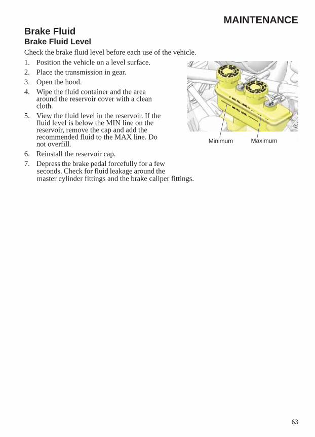
63
MAINTENANCEBrake FluidBrake Fluid LevelCheck the brake fluid level before each use of the vehicle. 1. Position the vehicle on a level surface.2. Place the transmission in gear.3. Open the hood.4. Wipe the fluid container and the area
around the reservoir cover with a clean cloth.
5. View the fluid level in the reservoir. If the fluid level is below the MIN line on the reservoir, remove the cap and add the recommended fluid to the MAX line. Do not overfill.
6. Reinstall the reservoir cap.7. Depress the brake pedal forcefully for a few
seconds. Check for fluid leakage around the master cylinder fittings and the brake caliper fittings.
MaximumMinimum
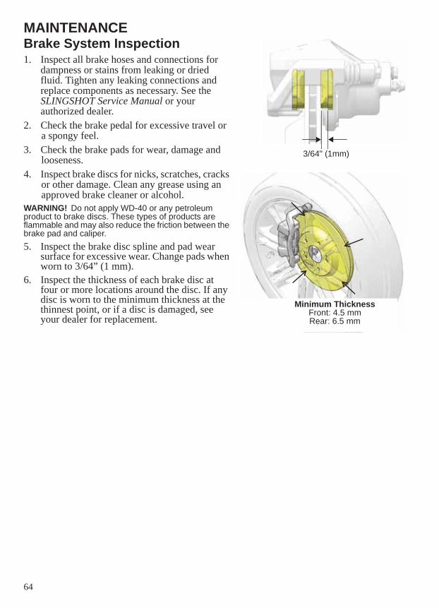
64
MAINTENANCEBrake System Inspection1. Inspect all brake hoses and connections for
dampness or stains from leaking or dried fluid. Tighten any leaking connections and replace components as necessary. See the SLINGSHOT Service Manual or your authorized dealer.
2. Check the brake pedal for excessive travel or a spongy feel.
3. Check the brake pads for wear, damage and looseness.
4. Inspect brake discs for nicks, scratches, cracks or other damage. Clean any grease using an approved brake cleaner or alcohol.
WARNING! Do not apply WD-40 or any petroleum product to brake discs. These types of products are flammable and may also reduce the friction between the brake pad and caliper.5. Inspect the brake disc spline and pad wear
surface for excessive wear. Change pads when worn to 3/64” (1 mm).
6. Inspect the thickness of each brake disc at four or more locations around the disc. If any disc is worn to the minimum thickness at the thinnest point, or if a disc is damaged, see your dealer for replacement.
3/64" (1mm)
Minimum ThicknessFront: 4.5 mmRear: 6.5 mm
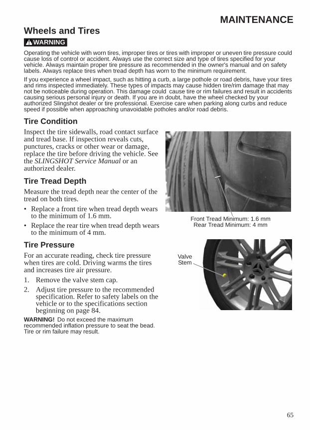
65
MAINTENANCEWheels and Tires
Operating the vehicle with worn tires, improper tires or tires with improper or uneven tire pressure could cause loss of control or accident. Always use the correct size and type of tires specified for your vehicle. Always maintain proper tire pressure as recommended in the owner's manual and on safety labels. Always replace tires when tread depth has worn to the minimum requirement.If you experience a wheel impact, such as hitting a curb, a large pothole or road debris, have your tires and rims inspected immediately. These types of impacts may cause hidden tire/rim damage that may not be noticeable during operation. This damage could cause tire or rim failures and result in accidents causing serious personal injury or death. If you are in doubt, have the wheel checked by your authorized Slingshot dealer or tire professional. Exercise care when parking along curbs and reduce speed if possible when approaching unavoidable potholes and/or road debris.
Tire ConditionInspect the tire sidewalls, road contact surface and tread base. If inspection reveals cuts, punctures, cracks or other wear or damage, replace the tire before driving the vehicle. See the SLINGSHOT Service Manual or an authorized dealer.
Tire Tread DepthMeasure the tread depth near the center of the tread on both tires. • Replace a front tire when tread depth wears
to the minimum of 1.6 mm.• Replace the rear tire when tread depth wears
to the minimum of 4 mm.
Tire PressureFor an accurate reading, check tire pressure when tires are cold. Driving warms the tires and increases tire air pressure.1. Remove the valve stem cap.2. Adjust tire pressure to the recommended
specification. Refer to safety labels on the vehicle or to the specifications section beginning on page 84.
WARNING! Do not exceed the maximum recommended inflation pressure to seat the bead. Tire or rim failure may result.
WARNING
Front Tread Minimum: 1.6 mmRear Tread Minimum: 4 mm
Valve Stem
66
MAINTENANCEWheels and TiresWheel InspectionInspect all wheels for cracks or other damage. Replace damaged wheels promptly. Do not operate the vehicle if wheels are damaged or cracked.
Wheel Removal1. Position the vehicle on a firm, level surface.2. Place the transmission in gear. 3. Engage the park brake.4. Position an appropriate floor jack under the frame at the side or rear of the vehicle, near
the wheel to be removed.5. If removing the rear wheel, place wheel chocks at the front of both front wheels to
prevent rolling.6. Elevate the vehicle until the wheel is slightly off the ground.7. Remove the wheel nuts and remove the wheel.
Wheel Installation1. With the transmission in gear and the park brake set, place the wheel on the wheel hub.
Be sure the valve stem is toward the outside and rotation arrows on the tire point toward forward rotation.
2. Install the wheel nuts and finger-tighten them.NOTE: On vehicles with tapered rear wheel nuts, make sure the tapered end of the nut goes into the
taper on the wheel.3. Tighten all wheel nuts to specification.
Torque: 75 ft-lbs (102 Nm)4. Lower the vehicle and remove the floor jack.
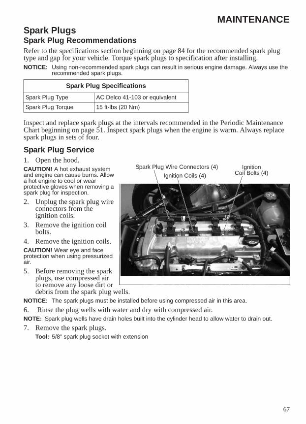
67
MAINTENANCESpark PlugsSpark Plug RecommendationsRefer to the specifications section beginning on page 84 for the recommended spark plug type and gap for your vehicle. Torque spark plugs to specification after installing.NOTICE: Using non-recommended spark plugs can result in serious engine damage. Always use the
recommended spark plugs.
Inspect and replace spark plugs at the intervals recommended in the Periodic Maintenance Chart beginning on page 51. Inspect spark plugs when the engine is warm. Always replace spark plugs in sets of four.
Spark Plug Service1. Open the hood.CAUTION! A hot exhaust system and engine can cause burns. Allow a hot engine to cool or wear protective gloves when removing a spark plug for inspection.2. Unplug the spark plug wire
connectors from the ignition coils.
3. Remove the ignition coil bolts.
4. Remove the ignition coils.CAUTION! Wear eye and face protection when using pressurized air. 5. Before removing the spark
plugs, use compressed air to remove any loose dirt or debris from the spark plug wells.
NOTICE: The spark plugs must be installed before using compressed air in this area.6. Rinse the plug wells with water and dry with compressed air.NOTE: Spark plug wells have drain holes built into the cylinder head to allow water to drain out.7. Remove the spark plugs.
Tool: 5/8” spark plug socket with extension
Spark Plug SpecificationsSpark Plug Type AC Delco 41-103 or equivalent
Spark Plug Torque 15 ft-lbs (20 Nm)
Spark Plug Wire Connectors (4) IgnitionCoil Bolts (4)Ignition Coils (4)
68
MAINTENANCESpark PlugsSpark Plug Service8. Inspect electrodes for wear and carbon buildup. A good plug will have a sharp outer
edge with no rounding or erosion of the electrodes.9. Do not attempt to adjust spark plug gap.10. Reinstall the spark plugs or install new plugs.11. Tighten spark plugs to specification.12. Reinstall the ignition coils.13. Reinstall the ignition coil bolts. Tighten to specification.
Torque: 7.5 ft-lbs (10 Nm)14. Connect the spark plug wires to the ignition coils.
Engine Compression TestAn engine compression test can be performed to monitor general engine condition. See the SLINGSHOT Service Manual or your authorized dealer.
Exhaust System InspectionCheck the exhaust system for stains from leaking exhaust gasses. Replace damaged or leaking exhaust gaskets. Tighten loose clamps and fasteners. See the SLINGSHOT Service Manual or your authorized dealer.
69
MAINTENANCEBattery
Improperly connecting or disconnecting battery cables can result in an explosion and cause serious injury or death. When removing the battery, always disconnect the negative (black) cable first. When reinstalling the battery, always connect the negative (black) cable last.
Battery electrolyte is poisonous. It contains sulfuric acid. Serious burns can result from contact with skin, eyes or clothing.Antidote:External: Flush with water.Internal: Drink large quantities of water or milk. Follow with milk of magnesia, beaten egg, or vegetable oil. Call physician immediately.Eyes: Flush with water for 15 minutes and get prompt medical attention.Batteries produce explosive gases. Keep sparks, flame, cigarettes, etc. away. Ventilate when charging or using in an enclosed space. Always shield eyes when working near batteries. KEEP OUT OF REACH OF CHILDREN.
Battery MaintenanceAlways keep battery terminals and connections free of corrosion. If cleaning is necessary, remove corrosion with a stiff wire brush. Wash with a solution of one tablespoon baking soda and one cup water. Rinse well with tap water and dry off with clean shop towels. Coat the terminals with dielectric grease or petroleum jelly. Be careful not to allow cleaning solution or tap water into a conventional battery.Make sure battery connections are tight. See page 71 for cable torque specifications.
WARNING
WARNING
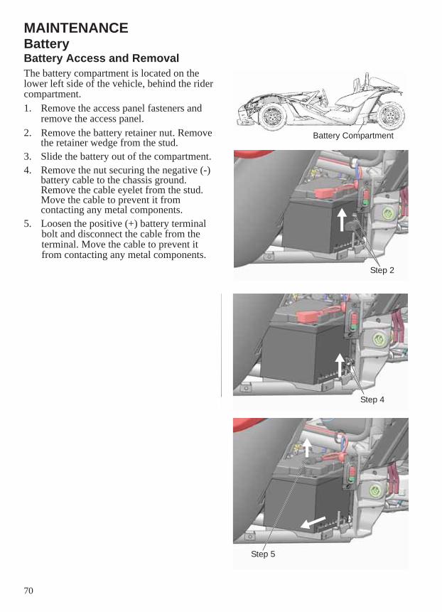
70
MAINTENANCEBatteryBattery Access and RemovalThe battery compartment is located on the lower left side of the vehicle, behind the rider compartment.1. Remove the access panel fasteners and
remove the access panel.2. Remove the battery retainer nut. Remove
the retainer wedge from the stud.3. Slide the battery out of the compartment.4. Remove the nut securing the negative (-)
battery cable to the chassis ground. Remove the cable eyelet from the stud. Move the cable to prevent it from contacting any metal components.
5. Loosen the positive (+) battery terminal bolt and disconnect the cable from the terminal. Move the cable to prevent it from contacting any metal components.
Battery Compartment
Step 2
Step 4
Step 5
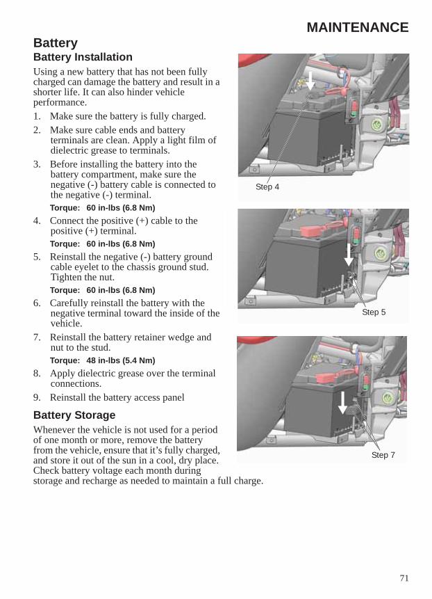
71
MAINTENANCEBatteryBattery InstallationUsing a new battery that has not been fully charged can damage the battery and result in a shorter life. It can also hinder vehicle performance.1. Make sure the battery is fully charged.2. Make sure cable ends and battery
terminals are clean. Apply a light film of dielectric grease to terminals.
3. Before installing the battery into the battery compartment, make sure the negative (-) battery cable is connected to the negative (-) terminal.Torque: 60 in-lbs (6.8 Nm)
4. Connect the positive (+) cable to the positive (+) terminal.Torque: 60 in-lbs (6.8 Nm)
5. Reinstall the negative (-) battery ground cable eyelet to the chassis ground stud. Tighten the nut.Torque: 60 in-lbs (6.8 Nm)
6. Carefully reinstall the battery with the negative terminal toward the inside of the vehicle.
7. Reinstall the battery retainer wedge and nut to the stud.Torque: 48 in-lbs (5.4 Nm)
8. Apply dielectric grease over the terminal connections.
9. Reinstall the battery access panel
Battery StorageWhenever the vehicle is not used for a period of one month or more, remove the battery from the vehicle, ensure that it’s fully charged, and store it out of the sun in a cool, dry place. Check battery voltage each month during storage and recharge as needed to maintain a full charge.
Step 7
Step 5
Step 4
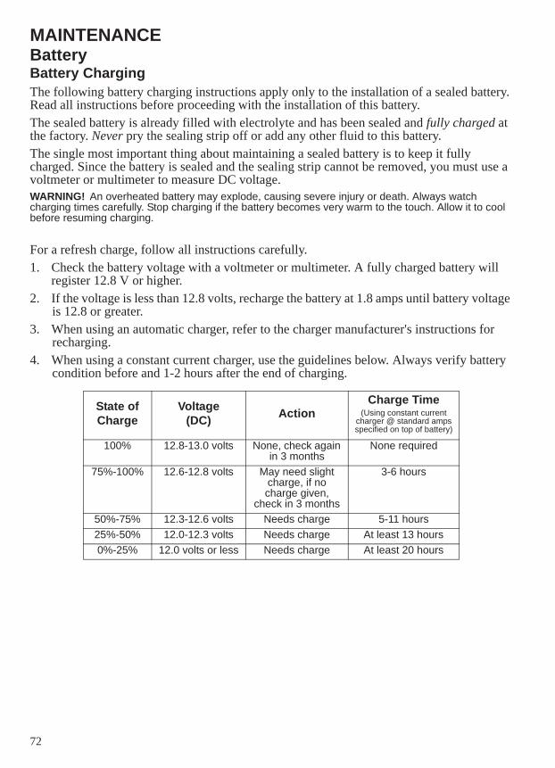
72
MAINTENANCEBatteryBattery ChargingThe following battery charging instructions apply only to the installation of a sealed battery. Read all instructions before proceeding with the installation of this battery.The sealed battery is already filled with electrolyte and has been sealed and fully charged at the factory. Never pry the sealing strip off or add any other fluid to this battery. The single most important thing about maintaining a sealed battery is to keep it fully charged. Since the battery is sealed and the sealing strip cannot be removed, you must use a voltmeter or multimeter to measure DC voltage.WARNING! An overheated battery may explode, causing severe injury or death. Always watch charging times carefully. Stop charging if the battery becomes very warm to the touch. Allow it to cool before resuming charging.
For a refresh charge, follow all instructions carefully.1. Check the battery voltage with a voltmeter or multimeter. A fully charged battery will
register 12.8 V or higher.2. If the voltage is less than 12.8 volts, recharge the battery at 1.8 amps until battery voltage
is 12.8 or greater. 3. When using an automatic charger, refer to the charger manufacturer's instructions for
recharging.4. When using a constant current charger, use the guidelines below. Always verify battery
condition before and 1-2 hours after the end of charging.
State of Charge
Voltage(DC) Action
Charge Time(Using constant current
charger @ standard ampsspecified on top of battery)
100% 12.8-13.0 volts None, check again in 3 months
None required
75%-100% 12.6-12.8 volts May need slight charge, if no charge given,
check in 3 months
3-6 hours
50%-75% 12.3-12.6 volts Needs charge 5-11 hours25%-50% 12.0-12.3 volts Needs charge At least 13 hours0%-25% 12.0 volts or less Needs charge At least 20 hours
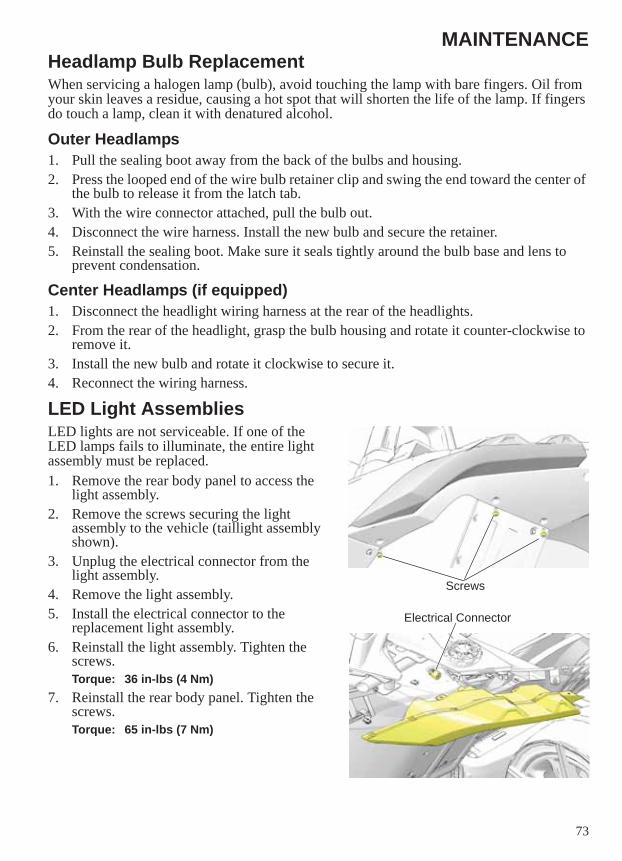
73
MAINTENANCEHeadlamp Bulb ReplacementWhen servicing a halogen lamp (bulb), avoid touching the lamp with bare fingers. Oil from your skin leaves a residue, causing a hot spot that will shorten the life of the lamp. If fingers do touch a lamp, clean it with denatured alcohol.
Outer Headlamps1. Pull the sealing boot away from the back of the bulbs and housing.2. Press the looped end of the wire bulb retainer clip and swing the end toward the center of
the bulb to release it from the latch tab.3. With the wire connector attached, pull the bulb out.4. Disconnect the wire harness. Install the new bulb and secure the retainer.5. Reinstall the sealing boot. Make sure it seals tightly around the bulb base and lens to
prevent condensation.
Center Headlamps (if equipped)1. Disconnect the headlight wiring harness at the rear of the headlights.2. From the rear of the headlight, grasp the bulb housing and rotate it counter-clockwise to
remove it.3. Install the new bulb and rotate it clockwise to secure it.4. Reconnect the wiring harness.
LED Light AssembliesLED lights are not serviceable. If one of the LED lamps fails to illuminate, the entire light assembly must be replaced.1. Remove the rear body panel to access the
light assembly.2. Remove the screws securing the light
assembly to the vehicle (taillight assembly shown).
3. Unplug the electrical connector from the light assembly.
4. Remove the light assembly.5. Install the electrical connector to the
replacement light assembly.6. Reinstall the light assembly. Tighten the
screws.Torque: 36 in-lbs (4 Nm)
7. Reinstall the rear body panel. Tighten the screws.Torque: 65 in-lbs (7 Nm)
Screws
Electrical Connector
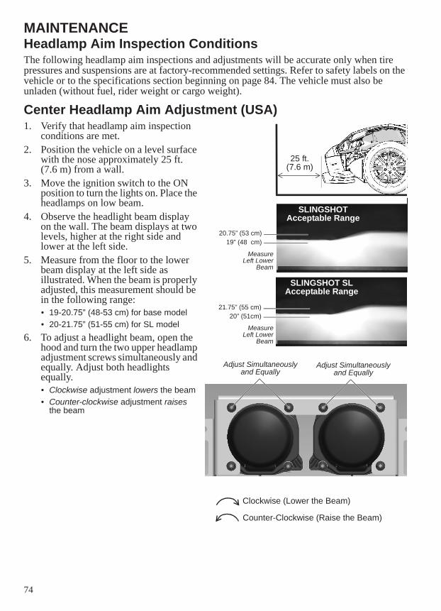
74
MAINTENANCEHeadlamp Aim Inspection ConditionsThe following headlamp aim inspections and adjustments will be accurate only when tire pressures and suspensions are at factory-recommended settings. Refer to safety labels on the vehicle or to the specifications section beginning on page 84. The vehicle must also be unladen (without fuel, rider weight or cargo weight).
Center Headlamp Aim Adjustment (USA)1. Verify that headlamp aim inspection
conditions are met. 2. Position the vehicle on a level surface
with the nose approximately 25 ft. (7.6 m) from a wall.
3. Move the ignition switch to the ON position to turn the lights on. Place the headlamps on low beam.
4. Observe the headlight beam display on the wall. The beam displays at two levels, higher at the right side and lower at the left side.
5. Measure from the floor to the lower beam display at the left side as illustrated. When the beam is properly adjusted, this measurement should be in the following range:• 19-20.75” (48-53 cm) for base model• 20-21.75” (51-55 cm) for SL model
6. To adjust a headlight beam, open the hood and turn the two upper headlamp adjustment screws simultaneously and equally. Adjust both headlights equally.• Clockwise adjustment lowers the beam• Counter-clockwise adjustment raises
the beam
Adjust Simultaneously and Equally
Adjust Simultaneously and Equally
Clockwise (Lower the Beam)
Counter-Clockwise (Raise the Beam)
20.75” (53 cm)19” (48 cm)
21.75” (55 cm)20” (51cm)
SLINGSHOT SL Acceptable Range
SLINGSHOT Acceptable Range
25 ft. (7.6 m)
MeasureLeft Lower
Beam
MeasureLeft Lower
Beam
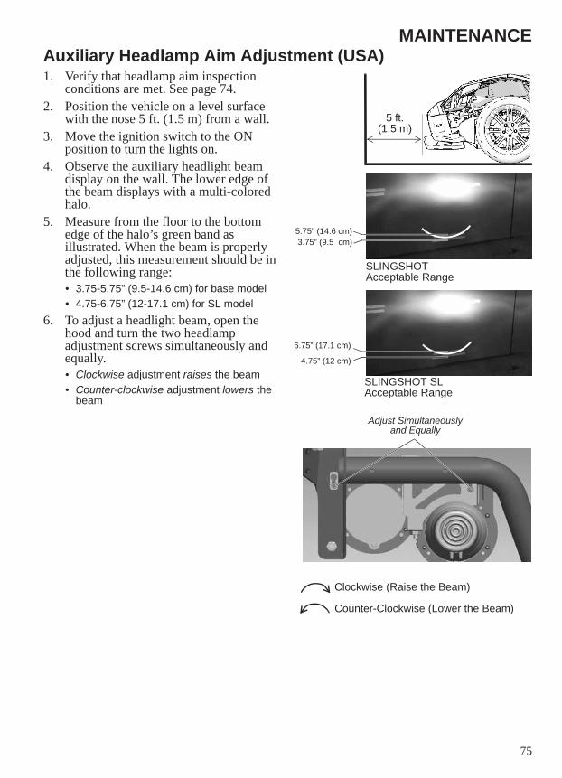
75
MAINTENANCEAuxiliary Headlamp Aim Adjustment (USA)1. Verify that headlamp aim inspection
conditions are met. See page 74.2. Position the vehicle on a level surface
with the nose 5 ft. (1.5 m) from a wall.3. Move the ignition switch to the ON
position to turn the lights on. 4. Observe the auxiliary headlight beam
display on the wall. The lower edge of the beam displays with a multi-colored halo.
5. Measure from the floor to the bottom edge of the halo’s green band as illustrated. When the beam is properly adjusted, this measurement should be in the following range:• 3.75-5.75” (9.5-14.6 cm) for base model• 4.75-6.75” (12-17.1 cm) for SL model
6. To adjust a headlight beam, open the hood and turn the two headlamp adjustment screws simultaneously and equally.• Clockwise adjustment raises the beam• Counter-clockwise adjustment lowers the
beam
5 ft. (1.5 m)
5.75” (14.6 cm)3.75” (9.5 cm)
6.75” (17.1 cm)
4.75” (12 cm)
SLINGSHOT Acceptable Range
SLINGSHOT SL Acceptable Range
Adjust Simultaneously and Equally
Clockwise (Raise the Beam)
Counter-Clockwise (Lower the Beam)
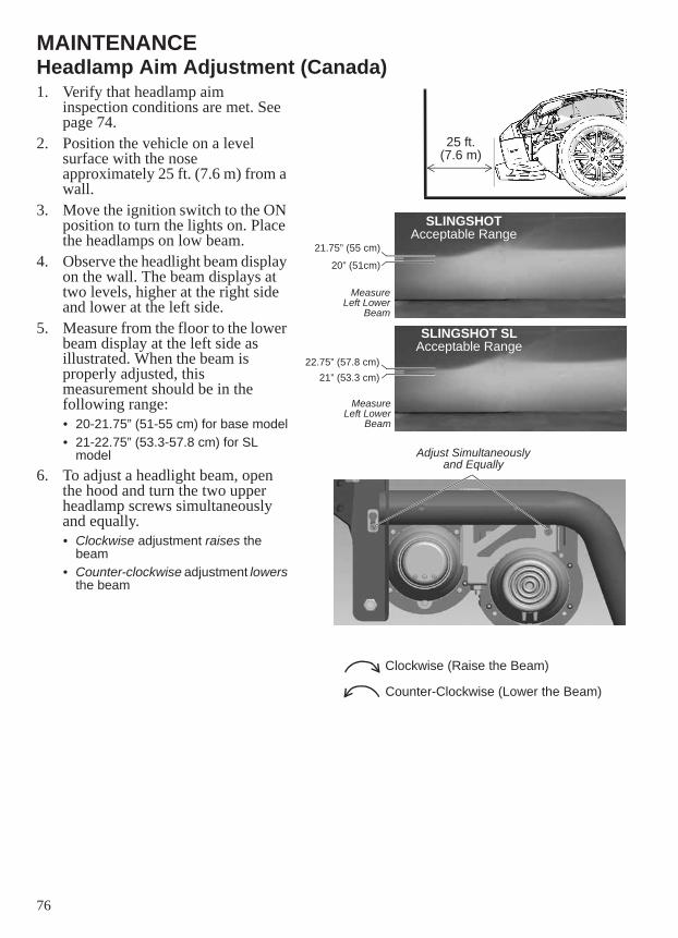
76
MAINTENANCEHeadlamp Aim Adjustment (Canada)1. Verify that headlamp aim
inspection conditions are met. See page 74.
2. Position the vehicle on a level surface with the nose approximately 25 ft. (7.6 m) from a wall.
3. Move the ignition switch to the ON position to turn the lights on. Place the headlamps on low beam.
4. Observe the headlight beam display on the wall. The beam displays at two levels, higher at the right side and lower at the left side.
5. Measure from the floor to the lower beam display at the left side as illustrated. When the beam is properly adjusted, this measurement should be in the following range:• 20-21.75” (51-55 cm) for base model• 21-22.75” (53.3-57.8 cm) for SL
model6. To adjust a headlight beam, open
the hood and turn the two upper headlamp screws simultaneously and equally.• Clockwise adjustment raises the
beam• Counter-clockwise adjustment lowers
the beam
Adjust Simultaneously and Equally
Clockwise (Raise the Beam)
Counter-Clockwise (Lower the Beam)
21.75” (55 cm)
20” (51cm)
22.75” (57.8 cm)21” (53.3 cm)
SLINGSHOT SL Acceptable Range
SLINGSHOT Acceptable Range
25 ft. (7.6 m)
MeasureLeft Lower
Beam
MeasureLeft Lower
Beam
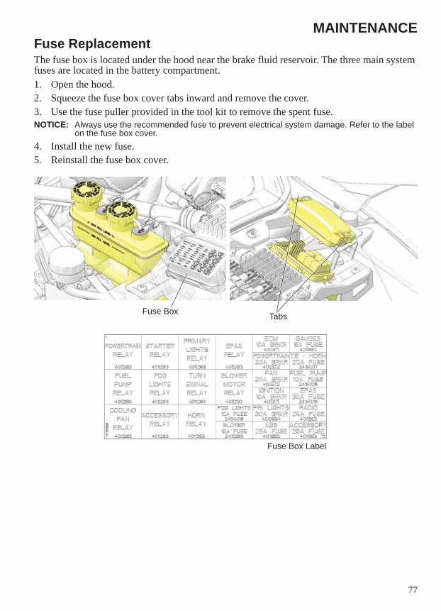
77
MAINTENANCEFuse ReplacementThe fuse box is located under the hood near the brake fluid reservoir. The three main system fuses are located in the battery compartment.1. Open the hood.2. Squeeze the fuse box cover tabs inward and remove the cover.3. Use the fuse puller provided in the tool kit to remove the spent fuse.NOTICE: Always use the recommended fuse to prevent electrical system damage. Refer to the label
on the fuse box cover.4. Install the new fuse.5. Reinstall the fuse box cover.
Fuse Box
Fuse Box Label
Tabs
78
CLEANING AND STORAGECleaning ProductsThis section provides tips on the very best way to clean, polish and preserve every surface of your beautiful new SLINGSHOT vehicle. We recommend the use of Polaris Engineered Vehicle Care cleaning and polishing products to offer the best care for your vehicle. After cleaning the vehicle, inspect for damage to the painted surfaces. Repair chips or scratches promptly by applying touch-up paint to prevent corrosion. For more information, or for answers to your cleaning and detailing questions, please see your SLINGSHOT dealer.
Washing the VehicleNOTICE: Do not use pressurized water to wash the SLINGSHOT vehicle. Water may seep in and
deteriorate wheel bearings, brake caliper assemblies, electrical connectors and transmission seals. Do not direct any water stream at air intakes, exhaust outlets, the radiator, the rider compartment or electrical components.
1. Do not use abrasive cleaners.2. Rinse off as much dirt and debris as possible with water running at low pressure. Use as
little water as possible when washing near the air intake or the exhaust pipe openings. Dry these components thoroughly before using the vehicle.
3. Make sure the brakes are functioning properly before riding.
79
CLEANING AND STORAGESeasonal StorageIf you will not operate the vehicle for 60 days or longer, such as during the winter, storing it properly will help prevent damage to the fuel system, electrical system, engine, suspensions, tires and body. During extended storage periods, maintain tire pressure and battery voltage at the recommended levels.1. Choose a dry, well-ventilated storage location away from direct sunlight, preferably a
garage or similar structure. The structure should have a firm, flat, clean surface free of oil and gasoline. The structure should have a relatively constant and moderate temperature.
2. Proper storage starts with cleaning, washing and waxing the hood, chassis, upholstery and plastic parts. Be sure that corrosive salt and acids are removed from surfaces before beginning preservation with waxes and rust inhibitors (grease, oil or paint). Clean and touch up with paint any rusted or previously painted surfaces.
3. Apply a light coat of oil or grease to all bushings, spindle shafts and tie rod ends.4. Change the engine oil. See page 53. Start the engine and allow it to idle just long enough
to circulate the new oil throughout the engine.5. Fog the engine using the recommended aerosol fogging oil available from your dealer.
Follow the instructions on the container.6. Treat the fuel system with a fuel stabilizer. If a fuel stabilizer is not used, the fuel tank,
fuel lines and fuel rail should be completely drained of gasoline.7. Remove the spark plugs. Spray a light amount of engine fogging oil into each cylinder to
prevent rust. Reinstall the plugs.8. Make sure the coolant quality and level in the system is adequate for freeze protection
during storage.9. Apply a metal protectant to shock absorber shafts or any exposed metal to prevent
corrosion.10. Separate electrical connector blocks and clean corrosive build-up from connectors.
Lubricate or pack connector blocks with Nyogel grease and reconnect. Replace worn or frayed electrical wire and connectors.
11. Prepare the battery for storage. See page 80.12. Verify that tire pressure is at specification. See page 65.13. Cover intake and exhaust openings to prevent small animals from entering.14. Elevate the vehicle using appropriate jack stands. Remove the wheels to prevent flat
spots on the tires. 15. Do not engage the park brake. If engaged, the brake pads may stick to the discs.16. Cover the vehicle with a fabric cover. Do not use plastic or vinyl covers, which trap
moisture and encourage rust and corrosion.
80
CLEANING AND STORAGEBattery Storage1. Remove the battery. See page 70.2. Clean the battery terminals first with a wire brush to remove any loose deposits.3. Wash the posts and the ends of the battery cables with a solution of one part baking soda
to 16 parts water. Rinse with clean water and wipe dry.4. Apply a thin film of dielectric grease to the posts and cable connectors.5. Clean the outside of the battery with a solution of mild detergent and warm water.6. Store the battery in a dry area with a temperature of 32° to 90° F (0° to 32° C).7. While in storage, fully charge the battery once a month. See page 72.
Removal From Storage1. Remove the fabric cover.2. Remove intake and exhaust opening covers (if covered for storage).3. Install the tires. Lower the vehicle and remove the jack stands.4. Verify that tire pressure is at specification. Refer to safety labels on the vehicle or to the
specifications section beginning on page 84.5. Install the battery and perform an electrical inspection.6. Inspect the spark plugs. Install new spark plugs if necessary.7. If the vehicle was stored in an area subject to wide swings in temperature and humidity
(such as outdoors), change the engine oil before starting the engine.NOTICE: During storage, temperature and humidity changes can cause condensation to form in the
crankcase and mix with engine oil. Running the engine with oil that contains condensation can cause engine damage.
8. Inspect the storage area for signs of fluid leaks. Identify and perform service to any leaking components.
9. Wash and polish the vehicle. Wax, polish or apply protectant to appropriate components.10. Perform the pre-ride inspections. See page 36.11. Check any fluid levels not included in the pre-ride inspection.
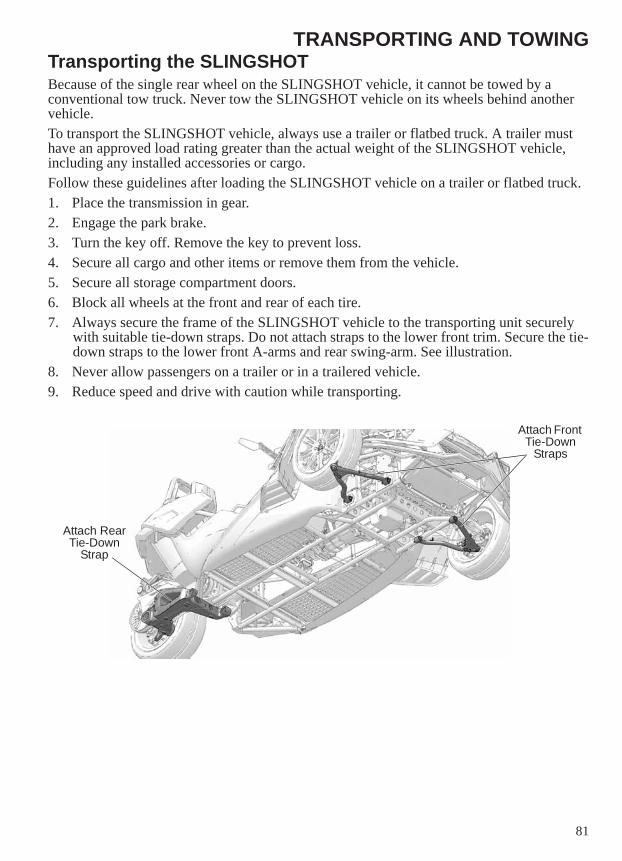
81
TRANSPORTING AND TOWINGTransporting the SLINGSHOTBecause of the single rear wheel on the SLINGSHOT vehicle, it cannot be towed by a conventional tow truck. Never tow the SLINGSHOT vehicle on its wheels behind another vehicle.To transport the SLINGSHOT vehicle, always use a trailer or flatbed truck. A trailer must have an approved load rating greater than the actual weight of the SLINGSHOT vehicle, including any installed accessories or cargo. Follow these guidelines after loading the SLINGSHOT vehicle on a trailer or flatbed truck.1. Place the transmission in gear.2. Engage the park brake.3. Turn the key off. Remove the key to prevent loss.4. Secure all cargo and other items or remove them from the vehicle.5. Secure all storage compartment doors.6. Block all wheels at the front and rear of each tire.7. Always secure the frame of the SLINGSHOT vehicle to the transporting unit securely
with suitable tie-down straps. Do not attach straps to the lower front trim. Secure the tie-down straps to the lower front A-arms and rear swing-arm. See illustration.
8. Never allow passengers on a trailer or in a trailered vehicle.9. Reduce speed and drive with caution while transporting.
Attach Rear Tie-Down
Strap
Attach Front Tie-Down
Straps
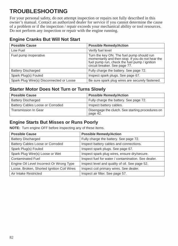
82
TROUBLESHOOTINGFor your personal safety, do not attempt inspection or repairs not fully described in this owner’s manual. Contact an authorized dealer for service if you cannot determine the cause of a problem or if the inspection / repair exceeds your mechanical ability or tool resources. Do not perform any inspection or repair with the engine running.
Engine Cranks But Will Not Start
Starter Motor Does Not Turn or Turns Slowly
Engine Starts But Misses or Runs PoorlyNOTE: Turn engine OFF before inspecting any of these items.
Possible Cause Possible Remedy/ActionLow Fuel Verify fuel levelFuel pump inoperative Turn the key ON. The fuel pump should run
momentarily and then stop. If you do not hear the fuel pump run, check the fuel pump / ignition circuit breaker. See page 77.
Battery Discharged Fully charge the battery. See page 72.Spark Plug(s) Fouled Inspect spark plugs. See page 67.Spark Plug Wire(s) Disconnected or Loose Be sure spark plug wires are securely fastened.
Possible Cause Possible Remedy/ActionBattery Discharged Fully charge the battery. See page 72.Battery Cables Loose or Corroded Inspect battery cables.Transmission In Gear Disengage the clutch. See starting procedures on
page 42.
Possible Cause Possible Remedy/ActionBattery Discharged Fully charge the battery. See page 72.Battery Cables Loose or Corroded Inspect battery cables and connections.Spark Plug(s) Fouled Inspect spark plugs. See page 67.Spark Plug Wire(s) Loose or Wet Inspect spark plug wires, ensure dry/secure.Contaminated Fuel Inspect fuel for water / contamination. See dealer.Engine Oil Level Incorrect Or Wrong Type Inspect level and quality of oil. See page 52.Loose, Broken, Shorted Ignition Coil Wires Inspect coil primary wires. See dealer.Air Intake Restricted Inspect air filter. See page 57.
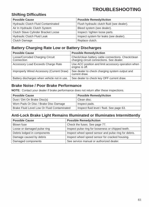
83
TROUBLESHOOTINGShifting Difficulties
Battery Charging Rate Low or Battery Discharges
Brake Noise / Poor Brake PerformanceNOTE: Contact your dealer if brake performance does not return after these inspections.
Anti-Lock Brake Light Remains Illuminated or Illuminates Intermittently
Possible Cause Possible Remedy/ActionHydraulic Clutch Fluid Contaminated Flush hydraulic clutch fluid (see dealer).Air In Hydraulic Clutch System Bleed system (see dealer).Clutch Slave Cylinder Bracket Loose Inspect / tighten loose parts.Hydraulic Clutch Fluid Leak Inspect system for leaks (see dealer).Clutch Damage Replace clutch.
Possible Cause Possible Remedy/ActionLoose/Corroded Charging Circuit Connection
Check/clean battery cable connections. Check/clean charging circuit connections. See dealer.
Accessory Load Exceeds Charge Rate Use ACC position and limit accessory operation when engine is off.
Improperly Wired Accessory (Current Draw) See dealer to check charging system output and current draw.
Battery discharges when vehicle not in use. See dealer to check key OFF current draw.
Possible Cause Possible Remedy/ActionDust / Dirt On Brake Disc(s) Clean disc.Worn Pads Or Disc / Brake Disc Damage Inspect pads. Brake Fluid Level Low Or Fluid Contaminated Inspect fluid level / fluid. See page 63.
Possible Cause Possible Remedy/ActionBlown fuse Check the fuses. See page 77.Loose or damaged pulse ring Inspect pulse ring for looseness or chipped teeth.Debris lodged in components Inspect wheel speed sensor and pulse ring for debris.Damage caused by debris Inspect wheel speed sensor for cracked housing.Damaged components See service manual or authorized dealer.
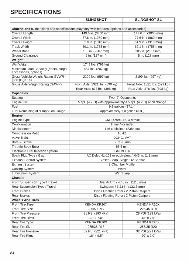
84
SPECIFICATIONS SLINGSHOT SLINGSHOT SL
Dimensions (Dimensions and specifications may vary with features, options and accessories)Overall Length 149.6 in. (3800 mm) 149.6 in. (3800 mm)Overall Width 77.6 in. (1960 mm) 77.6 in. (1960 mm)Overall Height 51.9 in. (1318 mm) 51.9 in. (1318 mm)Track Width 69.1 in. (1755 mm) 69.1 in. (1755 mm)Wheel Base 105 in. (2667 mm) 105 in. (2667 mm)Ground Clearance 5 in. (127 mm) 5 in. (127 mm)WeightWet Weight 1749 lbs. (793 kg)Maximum Load Capacity (riders, cargo, accessories, options)
457 lbs. (207 kg)
Gross Vehicle Weight Rating-GVWR(see page 14)
2199 lbs. (997 kg) 2199 lbs. (997 kg)
Gross Axle Weight Rating (GAWR) Front Axle: 1321 lbs. (599 kg) Front Axle: 1321 lbs. (599 kg)Rear Axle: 878 lbs. (398 kg) Rear Axle: 878 lbs. (398 kg)
CapacitiesSeating Two (2) OccupantsEngine Oil 5 qts. (4.75 l) with approximately 4.5 qts. (4.25 l) at oil changeFuel 9.8 gallons (37.1 l)Fuel Remaining at “Empty” on Gauge Approximately 1.0 gallon (3.8 l)EngineEngine Type GM Ecotec LE9 4-strokeConfiguration Inline 4-cylinderDisplacement 146 cubic inch (2384 cc)Compression Ratio 10.4:1Valve Train DOHC, VVTBore & Stroke 88 x 98 mmThrottle Body Bore 65.6 mmElectronic Fuel Injection System GM MEFI6Spark Plug Type / Gap AC Delco 41-103 or equivalent / .043 in. (1.1 mm)Exhaust Control System Closed-Loop, Single O2 SensorExhaust System 3-Chamber MufflerCooling System WaterLubrication System Wet SumpChassisFront Suspension Type / Travel Dual A-Arm / 4.43 in. (112.6 mm)Rear Suspension Type / Travel Swingarm / 5.23 in. (132.8 mm)Front Brakes Disc / Floating Rotor / 2 Piston CalipersRear Brakes Disc / Floating Rotor / 2 Piston CalipersWheels And TiresFront Tire Type KENDA KR20X KENDA KR20XFront Tire Size 205/50 R17 225/45 R18Front Tire Pressure 28 PSI (193 kPa) 28 PSI (193 kPa)Front Tire Rims 17” x 7.0” 18” x 7.5”Rear Tire Type KENDA KR20X KENDA KR20XRear Tire Size 265/35 R18 255/35 R20Rear Tire Pressure 32 PSI (221 kPa) 32 PSI (221 kPa)Rear Tire Rims 18” x 9.5” 20” x 9.0”
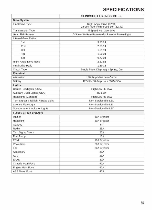
85
SPECIFICATIONSSLINGSHOT / SLINGSHOT SL
Drive SystemFinal Drive Type Right Angle Drive (37/16)
Carbon Fiber Reinforced Belt (62:39)Transmission Type 5 Speed with OverdriveGear Shift Pattern 5-Speed H-Gate Pattern with Reverse Down-RightInternal Gear Ratios
1st 3.753:12nd 2.258:13rd 1.512:14th 1.000:15th 0.729:1
Right Angle Drive Ratio 2.313:1Final Drive Ratio 1.590:1Clutch Type Single Plate, Diaphragm Spring, DryElectricalAlternator 140 Amp Maximum OutputBattery 12 Volt / 30 Amp Hour / 575 CCALightsCenter Headlights (USA) High/Low H9 65WAuxiliary Outer Lights (USA) H3 55WHeadlights (Canada) High/Low H3 55WTurn Signals / Taillight / Brake Light Non-Serviceable LEDLicense Plate Light Non-Serviceable LEDSpeedometer / Indicator Lights Non-Serviceable LED
Fuses / Circuit BreakersIgnition 10A BreakerHeadlight 30A BreakerGauges 5ARadio 25ATurn Signal / Horn 20AFuel Pump 10AECM 10A BreakerPowertrain 20A BreakerFan 20A BreakerAccessory 25AABS 25AEPAS 30AChassis Main Fuse 50AEngine Main Fuse 40AABS Motor Fuse 40A
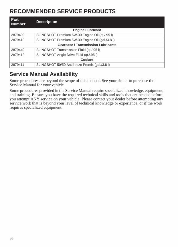
86
RECOMMENDED SERVICE PRODUCTS
Service Manual AvailabilitySome procedures are beyond the scope of this manual. See your dealer to purchase the Service Manual for your vehicle.Some procedures provided in the Service Manual require specialized knowledge, equipment, and training. Be sure you have the required technical skills and tools that are needed before you attempt ANY service on your vehicle. Please contact your dealer before attempting any service work that is beyond your level of technical knowledge or experience, or if the work requires specialized equipment.
Part Number Description
Engine Lubricant2879409 SLINGSHOT Premium 5W-30 Engine Oil (qt./.95 l)2879410 SLINGSHOT Premium 5W-30 Engine Oil (gal./3.8 l)
Gearcase / Transmission Lubricants2879440 SLINGSHOT Transmission Fluid (qt./.95 l)2879412 SLINGSHOT Angle Drive Fluid (qt./.95 l)
Coolant2879411 SLINGSHOT 50/50 Antifreeze Premix (gal./3.8 l)
87
WARRANTYLimited WarrantyPOLARIS Industries Inc., 2100 Highway 55, Medina, MN 55340 (POLARIS) gives a TWO YEAR LIMITED WARRANTY on all components of your POLARIS vehicle against defects in material or workmanship. This warranty covers parts and labor charges for repair or replacement of defective parts and begins on the date of purchase by the original retail purchaser. This warranty is transferable to another owner during the warranty period through an authorized POLARIS dealer, but any such transfer will not extend the original term of the warranty. The duration of this warranty may vary by international region based upon local laws and regulations.
RegistrationAt the time of sale, the Warranty Registration Form must be completed by your dealer and submitted to POLARIS within ten days of purchase. Upon receipt of this registration, POLARIS will record the registration for warranty. No verification of registration will be sent to the purchaser as the copy of the Warranty Registration Form will be your proof of warranty coverage. If you have not signed the original registration and received the customer copy, please contact your dealer immediately. NO WARRANTY COVERAGE WILL BE ALLOWED UNLESS YOUR VEHICLE IS REGISTERED WITH POLARIS. Initial dealer preparation and set-up of your vehicle is very important in ensuring trouble-free operation. Purchasing a vehicle in the crate or without proper dealer set-up will void your warranty coverage.
Warranty Coverage And Exclusions:Limitations Of Warranties And RemediesThis POLARIS limited warranty excludes any failures that are not caused by a defect in material or workmanship. THIS WARRANTY DOES NOT COVER CLAIMS OF DEFECTIVE DESIGN. This warranty also does not cover acts of God, accidental damage, normal wear and tear, abuse or improper handling. This warranty also does not cover any vehicle, component, or part that has been altered structurally, modified, neglected, improperly maintained or used for racing, competition or purposes other than for which it was designed. This warranty excludes damages or failures resulting from: improper lubrication; improper engine timing; improper fuel; surface imperfections caused by external stress, heat, cold or contamination; operator error or abuse; improper component alignment, tension, adjustment or altitude compensation; snow, water, dirt or other foreign substance ingestion/contamination; improper maintenance; modified components; use of aftermarket or unapproved components, accessories, or attachments; unauthorized repairs; or repairs made after the warranty period expires or by an unauthorized repair center. This warranty excludes damages or failures caused by abuse, accident, fire, or any other cause other than a defect in materials or workmanship and provides no coverage for consumable components, general wear items, or any parts exposed to friction surfaces, stresses, environmental conditions and/or contamination for which they were not designed or not intended, including but not limited to the following items:
• Wheels and tires • Finished and unfinished surfaces• Suspension components • Fuel Injectors/Throttle body components• Brake components • Engine components• Seat components • Drive belts• Clutches and components • Hydraulic components and fluids• Steering components • Circuit breakers/Fuses• Batteries • Electronic components• Light bulbs/Sealed beam lamps • Spark plugs• Filters • Sealants• Lubricants • Coolants• Bushings • Bearings
88
WARRANTYWarranty Coverage And Exclusions:Limitations Of Warranties And RemediesLubricants and Fluids1. Mixing oil brands or using non-recommended oil may cause engine damage. We recommend the use of POLARIS engine oil.2. Damage or failure resulting from the use of non-recommended lubricants or fluids is not covered by this warranty.This warranty provides no coverage for personal loss or expense, including mileage, transportation costs, hotels, meals, shipping or handling fees, vehicle pick-up or delivery, replacement rentals, loss of vehicle use, loss of profits or loss of vacation or personal time. THE EXCLUSIVE REMEDY FOR BREACH OF THIS WARRANTY SHALL BE, AT POLARIS' OPTION, REPAIR OR REPLACEMENT OF ANY DEFECTIVE MATERIALS, COMPONENTS, OR PRODUCTS. THE REMEDIES SET FORTH IN THIS WARRANTY ARE THE ONLY REMEDIES AVAILABLE TO ANY PERSON FOR BREACH OF THIS WARRANTY. POLARIS SHALL HAVE NO LIABILITY TO ANY PERSON FOR INCIDENTAL, CONSEQUENTIAL OR SPECIAL DAMAGES OF ANY DESCRIPTION, WHETHER ARISING OUT OF EXPRESS OR IMPLIED WARRANTY OR ANY OTHER CONTRACT, NEGLIGENCE, OR OTHER TORT OR OTHERWISE. THIS EXCLUSION OF CONSEQUENTIAL, INCIDENTAL, AND SPECIAL DAMAGES IS INDEPENDENT FROM AND SHALL SURVIVE ANY FINDING THAT THE EXCLUSIVE REMEDY FAILED OF ITS ESSENTIAL PURPOSE. THE IMPLIED WARRANTY OF FITNESS FOR A PARTICULAR PURPOSE IS EXCLUDED FROM THIS LIMITED WARRANTY. ALL OTHER IMPLIED WARRANTIES (INCLUDING BUT NOT LIMITED TO THE IMPLIED WARRANTY OF MERCHANTABILITY) ARE LIMITED IN DURATION TO THE ABOVE 24 MONTH WARRANTY PERIOD. POLARIS DISCLAIMS ALL EXPRESS WARRANTIES NOT STATED IN THIS WARRANTY. SOME STATES DO NOT PERMIT THE EXCLUSION OR LIMITATION OF INCIDENTAL OR CONSEQUENTIAL DAMAGES OR ALLOW LIMITATIONS ON THE DURATION OF IMPLIED WARRANTIES, SO THE ABOVE LIMITATIONS MAY NOT APPLY TO YOU IF INCONSISTENT WITH CONTROLLING STATE LAW.
89
WARRANTYHow To Obtain Warranty ServiceIf your vehicle requires warranty service, you must take it to a POLARIS Servicing Dealer. When requesting warranty service you must present your copy of the Warranty Registration Form to the dealer. (THE COST OF TRANSPORTATION TO AND FROM THE DEALER IS YOUR RESPONSIBILITY.) POLARIS suggests that you use your original selling dealer; however, you may use any POLARIS Servicing Dealer to perform warranty service.In the country where your product was purchased:Warranty or Service Bulletin repairs must be done by an authorized POLARIS dealer. If you move or are traveling within the country where your product was purchased, Warranty and Service Bulletin repairs may be requested from any authorized POLARIS dealer that sells the same line as your product.Outside the country where your product was purchased:If you are traveling temporarily outside the country where your product was purchased, you should take your product to an authorized POLARIS dealer. You must show the dealer photo identification from the country of the selling dealer’s authorized location as proof of residence. Upon residence verification, the servicing dealer will be authorized to perform the warranty repair.If you move:If you move to another country, be sure to contact POLARIS Customer Assistance and the customs department of the destination country before you move. Product importation rules vary considerably from country to country. You may be required to present documentation of your move to POLARIS in order to continue your warranty coverage. You may also be required to obtain documentation from POLARIS in order to register your product in your new country. You should warranty register your product at a local POLARIS dealer in your new country immediately after you move to continue your warranty coverage and to ensure that you receive information and notices regarding your vehicle.If you purchase from a private party:If you purchase a POLARIS product from a private party, to be kept and used outside of the country in which the product was originally purchased, all warranty coverage will be denied. You must nonetheless register your product under your name and address with a local POLARIS dealer in your country to ensure that you receive safety information and notices regarding your product.
Exported ProductsEXCEPT WHERE SPECIFICALLY REQUIRED BY LAW, THERE IS NO WARRANTY OR SERVICE BULLETIN COVERAGE ON THIS VEHICLE IF IT IS SOLD OUTSIDE THE COUNTRY OF THE SELLING DEALER’S AUTHORIZED LOCATION. This policy does not apply to vehicles that have received authorization for export from POLARIS. Dealers may not give authorization for export. You should consult an authorized dealer to determine this vehicle’s warranty or service coverage if you have any questions. This policy does not apply to vehicles registered to government officials or military personnel on assignment outside the country of the selling dealer’s authorized location. This policy does not apply to Safety Bulletins.
NoticeIf your vehicle is registered outside of the country where it was purchased and you have not followed the procedure set above, your vehicle will no longer be eligible for warranty or service bulletin coverage of any kind, other than safety bulletins. Vehicles registered to government officials or military personnel on assignment outside of the country where the vehicle was purchased will continue to be covered by the Limited Warranty.Please work with your dealer to resolve any warranty issues. Should your dealer require any additional assistance, they will contact the appropriate person at POLARIS.This warranty gives you specific legal rights, and you may also have other rights which vary from state to state or in different countries. If any of the above terms are void because of federal, state or local law, all other warranty terms will remain in effect.For questions call POLARIS Customer Assistance:United States & Canada: 1-800-POLARIS (1-800-765-2747)French: 1-800-268-6334
90
WARRANTYVehicle Noise RegulationTampering with noise control systems is prohibited. Federal law prohibits the following acts or causing thereof:• The removal or rendering inoperative by any person, other than for the purposes of maintenance, repair or
replacement of any device or element of design incorporated into any new vehicle for the purpose of noise control prior to its sale or delivery to the ultimate purchaser or while it is in use, or
• The use of the vehicle after such device or element of design has been removed or rendered inoperative by any person.
Among those acts presumed to constitute tampering are:• Removal or puncturing of the muffler, baffles, header pipes or any other component which conducts exhaust
gasses.• Removal or puncturing of any part of the intake system.• Lack of proper maintenance.• Replacing any moving part of the vehicle, or parts of the exhaust system or intake system, with parts other than
those specified by the manufacturer.This product should be checked for repair or replacement if the vehicle noise has increased significantly through use. Otherwise, the owner may become subject to penalties under state and local ordinances.
Noise Emission WarrantyPOLARIS warrants that this exhaust system, at the time of sale, meets all applicable U.S. EPA Federal noisestandards. This warranty extends to the first person who buys this exhaust system for purposes other than resale,and to all subsequent buyers.Warranty claims should be directed to:• An authorized POLARIS dealer, or• POLARIS Industries Inc., 2100 Highway 55, Medina, MN 55340
91
WARRANTYFederal Emissions Control System WarrantyThis Federal Emissions Control System Warranty Statement applies to your SLINGSHOT vehicle, which is certified to meet U.S. EPA emission standards. This same emissions warranty coverage applies to SLINGSHOT vehicles sold in Canada.
Your Warranty Rights and ObligationsIn the United States, new motor vehicles must be designed, built and equipped to meet applicable emission standards set forth in the Clean Air Act and in U.S. EPA regulations. POLARIS Industries Inc. (hereinafter POLARIS) must warrant the emission control system on your vehicle for the periods of time listed below provided there has been no abuse, neglect or improper maintenance of your vehicle. Your emission control system may include parts such as the fuel-injection system, ignition system, catalytic converter and engine computer. Also included may be hoses, belts, connectors and other emission-related assemblies. Where a warrantable condition exists, POLARIS will repair your vehicle at no cost to you, including diagnosis, parts and labor.
Manufacturer’s Warranty CoverageThe emissions warranty coverage for this vehicle is for a period of use of five (5) years or 30,000 kilometers (18,641 miles), whichever first occurs first. If an emission-related part on your vehicle is defective, the part will be repaired or replaced by POLARIS. This is your emission control system DEFECTS WARRANTY.
Owner’s Warranty ResponsibilitiesAs the vehicle owner, you are responsible for the performance of the required maintenance listed in your owner’s manual. POLARIS recommends that you retain all receipts covering maintenance on your vehicle, but POLARIS cannot deny warranty solely for the lack of receipts or for your failure to ensure the performance of all scheduled maintenance. You are responsible for presenting your vehicle to a POLARIS dealer as soon as a problem exists. The warranty repairs should be completed in a reasonable amount of time, not to exceed 30 days. As the vehicle owner, you should be aware that POLARIS may deny your warranty coverage if your vehicle or part has failed due to abuse, neglect, improper maintenance or unapproved modifications.If you have any questions regarding your federal emissions warranty rights and responsibilities, you should contact:• An authorized POLARIS dealer, or• POLARIS Industries Inc., 2100 Highway 55, Medina, MN 55340
or call 1-800-POLARIS (1-800-765-2747)
92
WARRANTYFederal Emissions Control System Warranty ProvisionsPOLARIS Industries Inc. (hereinafter POLARIS) warrants this vehicle includes as standard equipment a headlight, taillight and stoplight, and is street legal:A. It is designed, built and equipped so as to conform at the time of initial retail purchases with all applicable regulations of the United States Environmental Protection Agency; andB. It is free from defects in material and workmanship which cause such vehicle to fail to conform with applicable regulations of the United States Environmental Protection Agency for a period of use of 30,000 kilometers (18,641 miles) or five (5) years from the date of initial retail delivery, whichever occurs first.
l. CoverageWarranty defects shall be remedied during customary business hours at any authorized POLARIS dealer located within the United States of America in compliance with the Clean Air Act and applicable regulations of the United States Environmental Protection Agency. Any part or parts replaced under this warranty shall become the property of POLARIS.
ll. LimitationsThe Emission Control System Warranty shall not cover any of the following:A. Repair or replacement required as a result of:
• Accident• Misuse• Repairs improperly performed or replacements improperly installed• Use of replacement parts or accessories not conforming to POLARIS’ specifications which adversely affect
performance and/or• Use in competitive racing or related events.
B. Inspections, replacement of parts and other services and adjustments necessary for required maintenance.C. Any vehicle on which the odometer mileage has been changed so that actual mileage cannot be readily determined.
lll. Limited LiabilityA. The liability of POLARIS under this Emission Control System Warranty is limited solely to the remedying of defects in material or workmanship by an authorized POLARIS dealer at its place of business during customary business hours. This warranty does not cover inconvenience or loss of use of the vehicle or transportation of the vehicle to or from the POLARIS dealer. POLARIS SHALL NOT BE LIABLE FOR ANY OTHER EXPENSES, LOSS OR DAMAGE, WHETHER DIRECT, INCIDENTAL, CONSEQUENTIAL OR EXEMPLARY, ARISING IN CONNECTION WITH THE SALE OR USE OF OR INABILITY TO USE THE POLARIS VEHICLE FOR ANY PURPOSE. SOME STATES DO NOT ALLOW THE EXCLUSION OR LIMITATION OF ANY INCIDENTAL OR CONSEQUENTIAL DAMAGES, SO THE ABOVE LIMITATIONS MAY NOT APPLY TO YOU.B. NO EXPRESS EMISSION CONTROL SYSTEM WARRANTY IS GIVEN BY POLARIS EXCEPT AS SPECIFICALLY SET FORTH HEREIN. ANY EMISSION CONTROL SYSTEM WARRANTY IMPLIED BY LAW, INCLUDING ANY WARRANTY OF MERCHANTABILITY OR FITNESS FOR A PARTICULAR PURPOSE, IS LIMITED TO THE EXPRESS EMISSION CONTROL SYSTEM WARRANTY TERMS STATED IN THIS WARRANTY. THE FOREGOING STATEMENTS OF WARRANTY ARE EXCLUSIVE AND IN LIEU OF ALL OTHER REMEDIES. SOME STATES DO NOT ALLOW LIMITATIONS ON HOW LONG AN IMPLIED WARRANTY LASTS, SO THE ABOVE LIMITATIONS MAY NOT APPLY TO YOU.C. No dealer is authorized to modify this POLARIS Limited Emission Control System Warranty.
93
WARRANTYlV. Legal RightsTHIS WARRANTY GIVES YOU SPECIFIC LEGAL RIGHTS, AND YOU MAY ALSO HAVE OTHER RIGHTS WHICH VARY FROM STATE TO STATE.
V. This warranty is in addition to the POLARIS Limited Vehicle Warranty
Vl. Additional InformationAny replacement part that is equivalent in performance and durability may be used in the performance of any maintenance or repairs. However, POLARIS is not liable for these parts. The owner is responsible for the performance of all required maintenance. Such maintenance may be performed at a service establishment or by any individual. The warranty period begins on the date the vehicle is delivered to an ultimate purchaser.
POLARIS Industries Inc.2100 Highway 55Medina, MN 553401-800-POLARIS (1-800-765-2747)
94
WARRANTYCalifornia Emissions Control System WarrantyThis California Emissions Control System Warranty Statement applies to your SLINGSHOT vehicle, if it is certified to meet California Air Resources Board and US EPA emission control standards.
Your Warranty Rights and ObligationsThe California Air Resources Board and POLARIS Industries Inc. (hereinafter POLARIS) are pleased to explain the emission control system warranty on your SLINGSHOT vehicle. In California, new motor vehicles must be designed, built and equipped to meet the state’s stringent anti-smog standards. POLARIS must warrant the emission control system on your vehicle for the periods of time listed below provided there has been no abuse, neglect or improper maintenance of your vehicle. Your emission control system may include parts such as the fuel-injection system, ignition system, catalytic converter and engine computer. Also included may be hoses, belts, connectors and other emission-related assemblies. Where a warrantable condition exists, POLARIS will repair your vehicle at no cost to you, including diagnosis, parts and labor.
Manufacturer’s Warranty CoverageThe emissions warranty coverage for this vehicle is for a period of use of five (5) years or 30,000 kilometers (18,641 miles), whichever first occurs first. If an emission-related part on your vehicle is defective, the part will be repaired or replaced by POLARIS. This is your emission control system DEFECTS WARRANTY.
Owner’s Warranty ResponsibilitiesAs the vehicle owner, you are responsible for the performance of the required maintenance listed in your owner’s manual. POLARIS recommends that you retain all receipts covering maintenance on your vehicle, but POLARIS cannot deny warranty solely for the lack of receipts or for your failure to ensure the performance of all scheduled maintenance. You are responsible for presenting your vehicle to a POLARIS dealer as soon as a problem exists. The warranty repairs should be completed in a reasonable amount of time, not to exceed 30 days. As the vehicle owner, you should be aware that POLARIS may deny your warranty coverage if your vehicle or part has failed due to abuse, neglect, improper maintenance or unapproved modifications.If you have any questions regarding your warranty rights and responsibilities, you should contact:• An authorized POLARIS dealer, or• POLARIS Industries Inc., 2100 Highway 55, Medina, MN 55340
or call 1-800-POLARIS (1-800-765-2747), or• California Air Resources Board, P.O. Box 8001, 9528 Telstar Avenue, El Monte, CA 91731
95
WARRANTYCalifornia Emission Control System Warranty ProvisionsPOLARIS Industries Inc. (hereinafter POLARIS) warrants this vehicle includes as standard equipment a headlight, taillight and stoplight, and is street legal:A. It is designed, built and equipped so as to conform at the time of initial retail purchases with all applicable regulations of the United States Environmental Protection Agency and the California Air Resources Board; andB. It is free from defects in material and workmanship which cause such vehicle to fail to conform with applicable regulations of the United States Environmental Protection Agency or the California Air Resources Board for a period of use of 30,000 kilometers (18,641 miles) or five (5) years from the date of initial retail delivery, whichever occurs first.
l. CoverageWarranty defects shall be remedied during customary business hours at any authorized POLARIS dealer located within the United States of America in compliance with the Clean Air Act and applicable regulations of the United States Environmental Protection Agency and the California Air Resources Board. Any part or parts replaced under this warranty shall become the property of POLARIS.In the state of California only, emission-related warranted parts are specifically defined by the state’s Emission Warranty Parts List. These warranted parts are: carburetor and internal parts; intake manifold; fuel tank; fuel injection system; spark advance mechanism; crankcase breather; air cutoff valves; fuel tank cap for evaporative emission controlled vehicles; oil filler cap; pressure control valve; fuel/vapor separator; canister; igniters; breaker governors; ignition coils; ignition wires; ignition points; condensers and spark plugs if failure occurs prior to the first scheduled replacement; and hoses, clamps, fittings and tubing used directly in these parts. Since emission-related parts may vary from model to model, certain models may not contain all of these parts and certain models may contain functionally equivalent parts.In the state of California only, Emission Control System emergency repairs, as provided for in the California Administrative Code, may be performed by other than an authorized a POLARIS dealer. An emergency situation occurs when an authorized POLARIS dealer is not reasonably available, a part is not available within 30 days or a repair is not complete within 30 days. Any replacement part can be used in an emergency repair. POLARIS will reimburse the owner for expenses, including diagnosis, not to exceed POLARIS’ suggested retail price for all warranted parts replaced, and labor charges based on POLARIS’ recommended time allowance for the warranty repair and the geographically appropriate hourly labor rate. The owner may be required to keep receipts and failed parts in order to receive compensation.
ll. LimitationsThe Emission Control System Warranty shall not cover any of the following:A. Repair or replacement required as a result of:
• Accident• Misuse• Repairs improperly performed or replacements improperly installed• Use of replacement parts or accessories not conforming to POLARIS’ specifications which adversely affect
performance and/or• Use in competitive racing or related events.
B. Inspections, replacement of parts and other services and adjustments necessary for required maintenance.C. Any vehicle on which the odometer mileage has been changed so that actual mileage cannot be readily determined.
96
WARRANTYlll. Limited LiabilityA. The liability of POLARIS under this Emission Control System Warranty is limited solely to the remedying of defects in material or workmanship by an authorized POLARIS dealer at its place of business during customary business hours. This warranty does not cover inconvenience or loss of use of the vehicle or transportation of the vehicle to or from the POLARIS dealer. POLARIS SHALL NOT BE LIABLE FOR ANY OTHER EXPENSES, LOSS OR DAMAGE, WHETHER DIRECT, INCIDENTAL, CONSEQUENTIAL OR EXEMPLARY, ARISING IN CONNECTION WITH THE SALE OR USE OF OR INABILITY TO USE THE POLARIS VEHICLE FOR ANY PURPOSE. SOME STATES DO NOT ALLOW THE EXCLUSION OR LIMITATION OF ANY INCIDENTAL OR CONSEQUENTIAL DAMAGES, SO THE ABOVE LIMITATIONS MAY NOT APPLY TO YOU.B. NO EXPRESS EMISSION CONTROL SYSTEM WARRANTY IS GIVEN BY POLARIS EXCEPT AS SPECIFICALLY SET FORTH HEREIN. ANY EMISSION CONTROL SYSTEM WARRANTY IMPLIED BY LAW, INCLUDING ANY WARRANTY OF MERCHANTABILITY OR FITNESS FOR A PARTICULAR PURPOSE, IS LIMITED TO THE EXPRESS EMISSION CONTROL SYSTEM WARRANTY TERMS STATED IN THIS WARRANTY. THE FOREGOING STATEMENTS OF WARRANTY ARE EXCLUSIVE AND IN LIEU OF ALL OTHER REMEDIES. SOME STATES DO NOT ALLOW LIMITATIONS ON HOW LONG AN IMPLIED WARRANTY LASTS, SO THE ABOVE LIMITATIONS MAY NOT APPLY TO YOU.C. No dealer is authorized to modify this POLARIS Limited Emission Control System Warranty.
lV. Legal RightsTHIS WARRANTY GIVES YOU SPECIFIC LEGAL RIGHTS, AND YOU MAY ALSO HAVE OTHER RIGHTS WHICH VARY FROM STATE TO STATE.
V. This warranty is in addition to the POLARIS Limited Vehicle Warranty
Vl. Additional InformationAny replacement part that is equivalent in performance and durability may be used in the performance of any maintenance or repairs. However, POLARIS is not liable for these parts. The owner is responsible for the performance of all required maintenance. Such maintenance may be performed at a service establishment or by any individual. The warranty period begins on the date the vehicle is delivered to an ultimate purchaser.
POLARIS Industries Inc.2100 Highway 55Medina, MN 553401-800-POLARIS (1-800-765-2747)
97
MAINTENANCE LOGMaintenance Performed Miles / Km Notes Performed
by
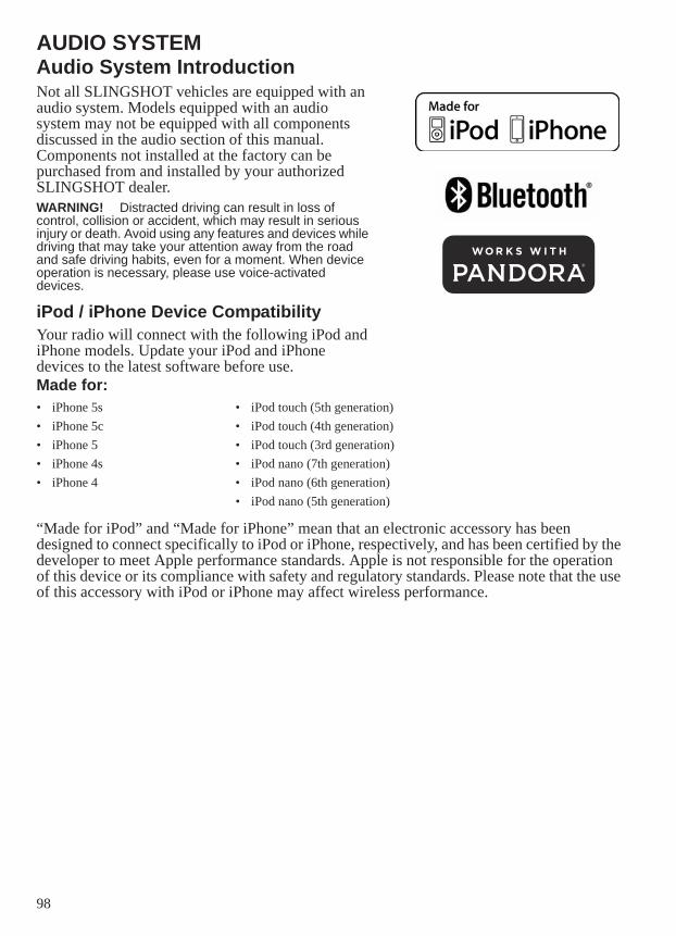
98
AUDIO SYSTEMAudio System IntroductionNot all SLINGSHOT vehicles are equipped with an audio system. Models equipped with an audio system may not be equipped with all components discussed in the audio section of this manual. Components not installed at the factory can be purchased from and installed by your authorized SLINGSHOT dealer.WARNING! Distracted driving can result in loss of control, collision or accident, which may result in serious injury or death. Avoid using any features and devices while driving that may take your attention away from the road and safe driving habits, even for a moment. When device operation is necessary, please use voice-activated devices.
iPod / iPhone Device CompatibilityYour radio will connect with the following iPod and iPhone models. Update your iPod and iPhone devices to the latest software before use.Made for:
“Made for iPod” and “Made for iPhone” mean that an electronic accessory has been designed to connect specifically to iPod or iPhone, respectively, and has been certified by the developer to meet Apple performance standards. Apple is not responsible for the operation of this device or its compliance with safety and regulatory standards. Please note that the use of this accessory with iPod or iPhone may affect wireless performance.
• iPhone 5s • iPod touch (5th generation)• iPhone 5c • iPod touch (4th generation)• iPhone 5 • iPod touch (3rd generation)• iPhone 4s • iPod nano (7th generation)• iPhone 4 • iPod nano (6th generation)
• iPod nano (5th generation)
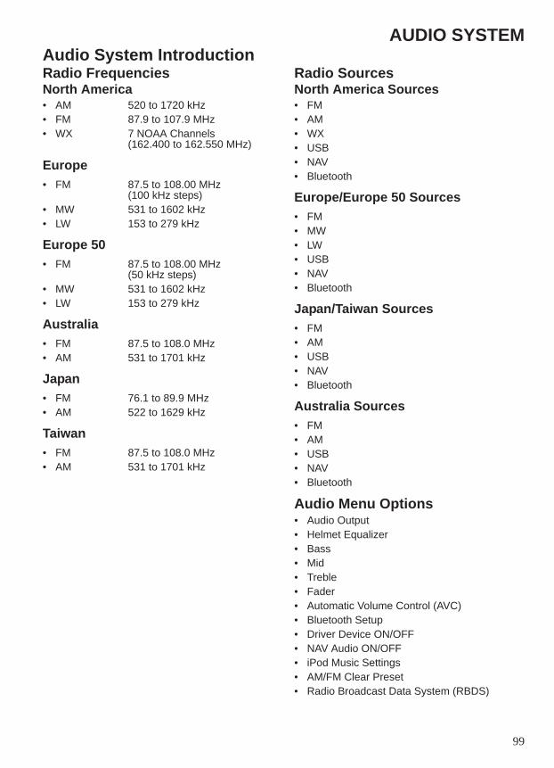
99
AUDIO SYSTEMAudio System IntroductionRadio FrequenciesNorth America• AM 520 to 1720 kHz• FM 87.9 to 107.9 MHz• WX 7 NOAA Channels
(162.400 to 162.550 MHz)
Europe• FM 87.5 to 108.00 MHz
(100 kHz steps)• MW 531 to 1602 kHz• LW 153 to 279 kHz
Europe 50• FM 87.5 to 108.00 MHz
(50 kHz steps)• MW 531 to 1602 kHz• LW 153 to 279 kHz
Australia• FM 87.5 to 108.0 MHz• AM 531 to 1701 kHz
Japan• FM 76.1 to 89.9 MHz• AM 522 to 1629 kHz
Taiwan• FM 87.5 to 108.0 MHz• AM 531 to 1701 kHz
Radio SourcesNorth America Sources• FM• AM• WX• USB• NAV• Bluetooth
Europe/Europe 50 Sources• FM• MW• LW• USB• NAV• Bluetooth
Japan/Taiwan Sources• FM• AM• USB• NAV• Bluetooth
Australia Sources• FM• AM• USB• NAV• Bluetooth
Audio Menu Options• Audio Output• Helmet Equalizer• Bass• Mid• Treble• Fader• Automatic Volume Control (AVC)• Bluetooth Setup• Driver Device ON/OFF• NAV Audio ON/OFF• iPod Music Settings• AM/FM Clear Preset• Radio Broadcast Data System (RBDS)
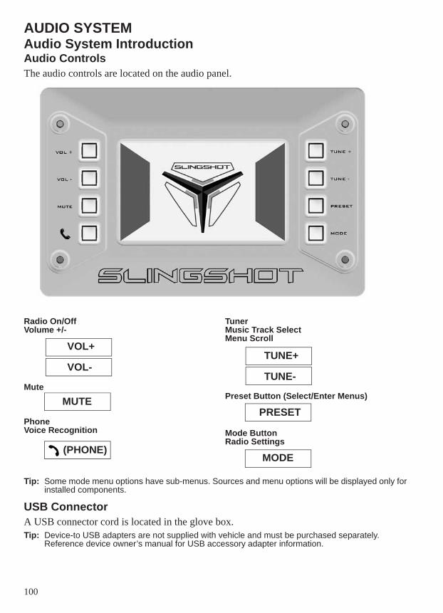
100
AUDIO SYSTEMAudio System IntroductionAudio ControlsThe audio controls are located on the audio panel.
Radio On/OffVolume +/-
Mute
PhoneVoice Recognition
TunerMusic Track SelectMenu Scroll
Preset Button (Select/Enter Menus)
Mode ButtonRadio Settings
Tip: Some mode menu options have sub-menus. Sources and menu options will be displayed only for installed components.
USB ConnectorA USB connector cord is located in the glove box.Tip: Device-to USB adapters are not supplied with vehicle and must be purchased separately.
Reference device owner’s manual for USB accessory adapter information.
VOL+
VOL-
MUTE
(PHONE)
TUNE+
TUNE-
PRESET
MODE
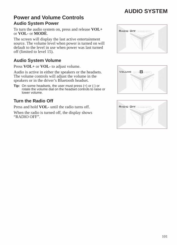
101
AUDIO SYSTEMPower and Volume ControlsAudio System PowerTo turn the audio system on, press and release VOL+ or VOL- or MODE.The screen will display the last active entertainment source. The volume level when power is turned on will default to the level in use when power was last turned off (limited to level 15).
Audio System VolumePress VOL+ or VOL- to adjust volume.Audio is active in either the speakers or the headsets. The volume controls will adjust the volume in the speakers or in the driver’s Bluetooth headset.Tip: On some headsets, the user must press (+) or (-) or
rotate the volume dial on the headset controls to raise or lower volume.
Turn the Radio Off Press and hold VOL- until the radio turns off.When the radio is turned off, the display shows “RADIO OFF”.
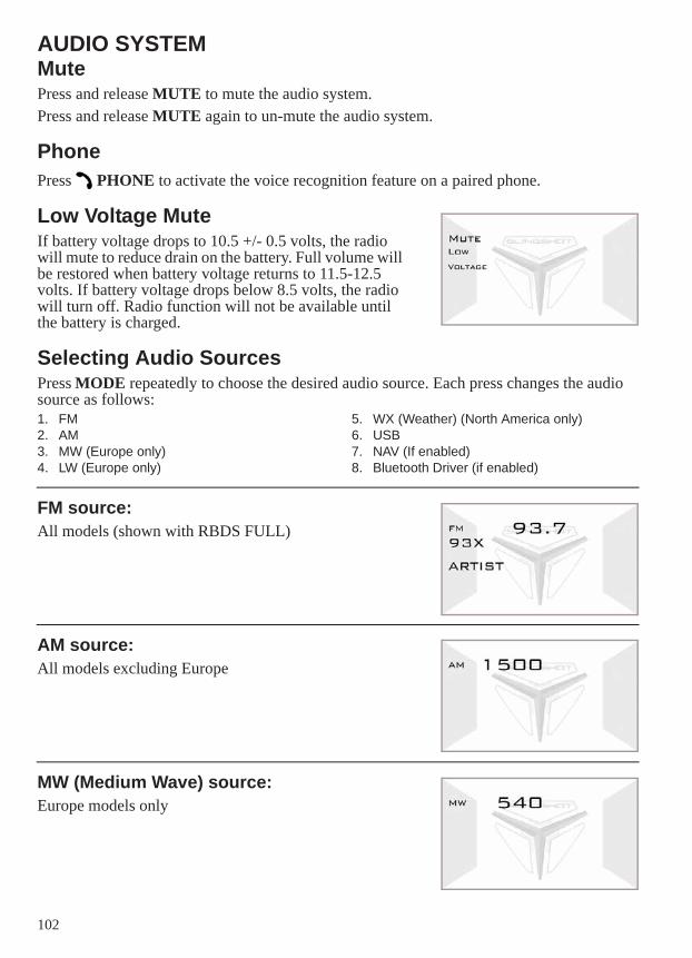
102
AUDIO SYSTEMMutePress and release MUTE to mute the audio system.Press and release MUTE again to un-mute the audio system.
PhonePress PHONE to activate the voice recognition feature on a paired phone.
Low Voltage MuteIf battery voltage drops to 10.5 +/- 0.5 volts, the radio will mute to reduce drain on the battery. Full volume will be restored when battery voltage returns to 11.5-12.5 volts. If battery voltage drops below 8.5 volts, the radio will turn off. Radio function will not be available until the battery is charged.
Selecting Audio SourcesPress MODE repeatedly to choose the desired audio source. Each press changes the audio source as follows:1. FM2. AM3. MW (Europe only)4. LW (Europe only)
5. WX (Weather) (North America only)6. USB7. NAV (If enabled)8. Bluetooth Driver (if enabled)
FM source:All models (shown with RBDS FULL)
AM source:All models excluding Europe
MW (Medium Wave) source:Europe models only
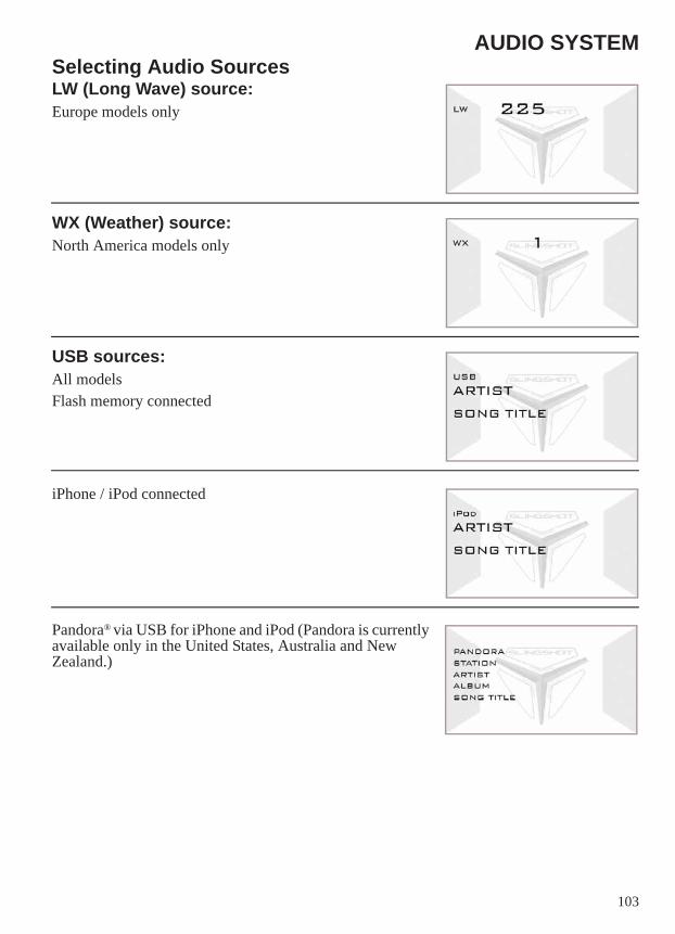
103
AUDIO SYSTEMSelecting Audio SourcesLW (Long Wave) source:Europe models only
WX (Weather) source:North America models only
USB sources:All modelsFlash memory connected
iPhone / iPod connected
Pandora® via USB for iPhone and iPod (Pandora is currently available only in the United States, Australia and New Zealand.)
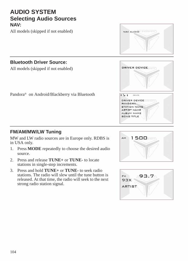
104
AUDIO SYSTEMSelecting Audio SourcesNAV:All models (skipped if not enabled)
Bluetooth Driver Source:All models (skipped if not enabled)
Pandora® on Android/Blackberry via Bluetooth
FM/AM/MW/LW TuningMW and LW radio sources are in Europe only. RDBS is in USA only.1. Press MODE repeatedly to choose the desired audio
source.2. Press and release TUNE+ or TUNE- to locate
stations in single-step increments.3. Press and hold TUNE+ or TUNE- to seek radio
stations. The radio will slew until the tune button is released. At that time, the radio will seek to the next strong radio station signal.
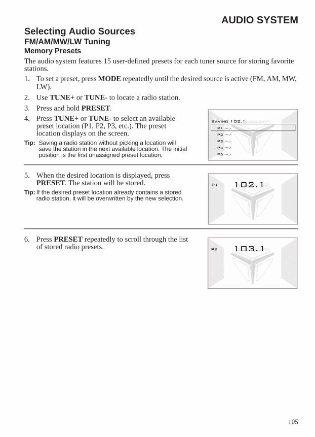
105
AUDIO SYSTEMSelecting Audio SourcesFM/AM/MW/LW TuningMemory PresetsThe audio system features 15 user-defined presets for each tuner source for storing favorite stations.1. To set a preset, press MODE repeatedly until the desired source is active (FM, AM, MW,
LW).2. Use TUNE+ or TUNE- to locate a radio station.3. Press and hold PRESET.4. Press TUNE+ or TUNE- to select an available
preset location (P1, P2, P3, etc.). The preset location displays on the screen.
Tip: Saving a radio station without picking a location will save the station in the next available location. The initial position is the first unassigned preset location.
5. When the desired location is displayed, press PRESET. The station will be stored.
Tip: If the desired preset location already contains a stored radio station, it will be overwritten by the new selection.
6. Press PRESET repeatedly to scroll through the list of stored radio presets.
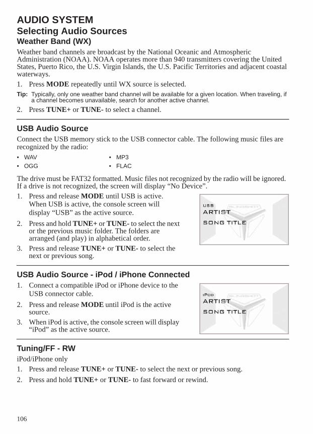
106
AUDIO SYSTEMSelecting Audio SourcesWeather Band (WX)Weather band channels are broadcast by the National Oceanic and Atmospheric Administration (NOAA). NOAA operates more than 940 transmitters covering the United States, Puerto Rico, the U.S. Virgin Islands, the U.S. Pacific Territories and adjacent coastal waterways.1. Press MODE repeatedly until WX source is selected.Tip: Typically, only one weather band channel will be available for a given location. When traveling, if
a channel becomes unavailable, search for another active channel.2. Press TUNE+ or TUNE- to select a channel.
USB Audio SourceConnect the USB memory stick to the USB connector cable. The following music files are recognized by the radio:
The drive must be FAT32 formatted. Music files not recognized by the radio will be ignored. If a drive is not recognized, the screen will display “No Device”.1. Press and release MODE until USB is active.
When USB is active, the console screen will display “USB” as the active source.
2. Press and hold TUNE+ or TUNE- to select the next or the previous music folder. The folders are arranged (and play) in alphabetical order.
3. Press and release TUNE+ or TUNE- to select the next or previous song.
USB Audio Source - iPod / iPhone Connected1. Connect a compatible iPod or iPhone device to the
USB connector cable.2. Press and release MODE until iPod is the active
source.3. When iPod is active, the console screen will display
“iPod” as the active source.
Tuning/FF - RWiPod/iPhone only1. Press and release TUNE+ or TUNE- to select the next or previous song.2. Press and hold TUNE+ or TUNE- to fast forward or rewind.
• WAV • MP3• OGG • FLAC
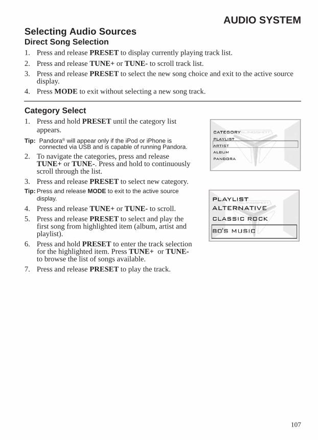
107
AUDIO SYSTEMSelecting Audio SourcesDirect Song Selection1. Press and release PRESET to display currently playing track list.2. Press and release TUNE+ or TUNE- to scroll track list.3. Press and release PRESET to select the new song choice and exit to the active source
display.4. Press MODE to exit without selecting a new song track.
Category Select1. Press and hold PRESET until the category list
appears.Tip: Pandora® will appear only if the iPod or iPhone is
connected via USB and is capable of running Pandora.2. To navigate the categories, press and release
TUNE+ or TUNE-. Press and hold to continuously scroll through the list.
3. Press and release PRESET to select new category.Tip: Press and release MODE to exit to the active source
display.
4. Press and release TUNE+ or TUNE- to scroll.5. Press and release PRESET to select and play the
first song from highlighted item (album, artist and playlist).
6. Press and hold PRESET to enter the track selection for the highlighted item. Press TUNE+ or TUNE- to browse the list of songs available.
7. Press and release PRESET to play the track.
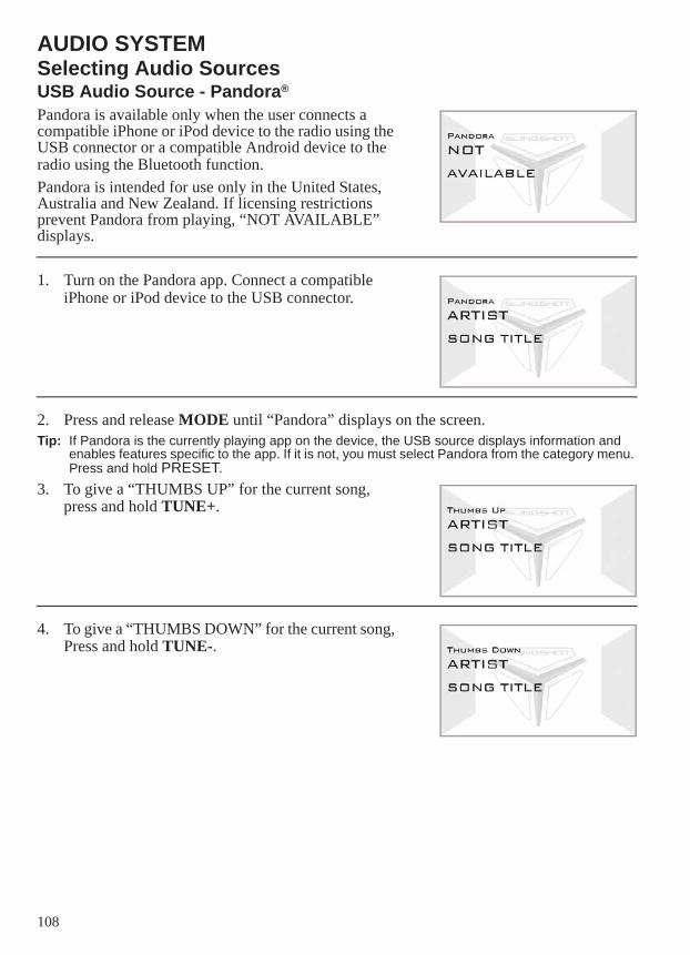
108
AUDIO SYSTEMSelecting Audio SourcesUSB Audio Source - Pandora®
Pandora is available only when the user connects a compatible iPhone or iPod device to the radio using the USB connector or a compatible Android device to the radio using the Bluetooth function.Pandora is intended for use only in the United States, Australia and New Zealand. If licensing restrictions prevent Pandora from playing, “NOT AVAILABLE” displays.
1. Turn on the Pandora app. Connect a compatible iPhone or iPod device to the USB connector.
2. Press and release MODE until “Pandora” displays on the screen.Tip: If Pandora is the currently playing app on the device, the USB source displays information and
enables features specific to the app. If it is not, you must select Pandora from the category menu. Press and hold PRESET.
3. To give a “THUMBS UP” for the current song, press and hold TUNE+.
4. To give a “THUMBS DOWN” for the current song, Press and hold TUNE-.
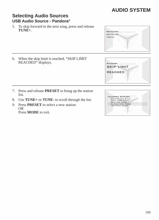
109
AUDIO SYSTEMSelecting Audio SourcesUSB Audio Source - Pandora®
5. To skip forward to the next song, press and release TUNE+.
6. When the skip limit is reached, “SKIP LIMIT REACHED” displays.
7. Press and release PRESET to bring up the station list.
8. Use TUNE+ or TUNE- to scroll through the list. 9. Press PRESET to select a new station.
ORPress MODE to exit.
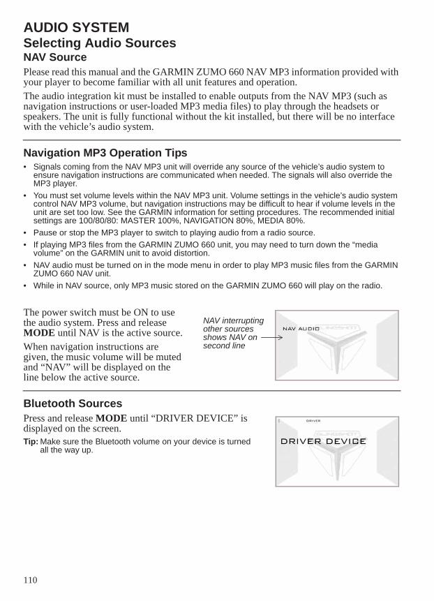
110
AUDIO SYSTEMSelecting Audio SourcesNAV SourcePlease read this manual and the GARMIN ZUMO 660 NAV MP3 information provided with your player to become familiar with all unit features and operation.The audio integration kit must be installed to enable outputs from the NAV MP3 (such as navigation instructions or user-loaded MP3 media files) to play through the headsets or speakers. The unit is fully functional without the kit installed, but there will be no interface with the vehicle’s audio system.
Navigation MP3 Operation Tips• Signals coming from the NAV MP3 unit will override any source of the vehicle’s audio system to
ensure navigation instructions are communicated when needed. The signals will also override the MP3 player.
• You must set volume levels within the NAV MP3 unit. Volume settings in the vehicle’s audio system control NAV MP3 volume, but navigation instructions may be difficult to hear if volume levels in the unit are set too low. See the GARMIN information for setting procedures. The recommended initial settings are 100/80/80: MASTER 100%, NAVIGATION 80%, MEDIA 80%.
• Pause or stop the MP3 player to switch to playing audio from a radio source.• If playing MP3 files from the GARMIN ZUMO 660 unit, you may need to turn down the “media
volume” on the GARMIN unit to avoid distortion.• NAV audio must be turned on in the mode menu in order to play MP3 music files from the GARMIN
ZUMO 660 NAV unit.• While in NAV source, only MP3 music stored on the GARMIN ZUMO 660 will play on the radio.
The power switch must be ON to use the audio system. Press and release MODE until NAV is the active source.When navigation instructions are given, the music volume will be muted and “NAV” will be displayed on the line below the active source.
Bluetooth SourcesPress and release MODE until “DRIVER DEVICE” is displayed on the screen.Tip: Make sure the Bluetooth volume on your device is turned
all the way up.
NAV interrupting other sources shows NAV on second line
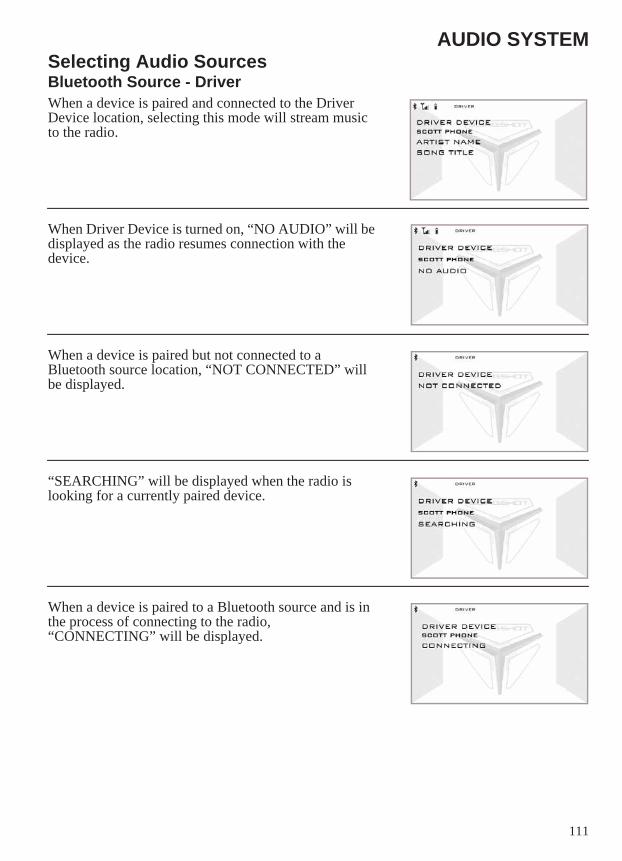
111
AUDIO SYSTEMSelecting Audio SourcesBluetooth Source - DriverWhen a device is paired and connected to the Driver Device location, selecting this mode will stream music to the radio.
When Driver Device is turned on, “NO AUDIO” will be displayed as the radio resumes connection with the device.
When a device is paired but not connected to a Bluetooth source location, “NOT CONNECTED” will be displayed.
“SEARCHING” will be displayed when the radio is looking for a currently paired device.
When a device is paired to a Bluetooth source and is in the process of connecting to the radio, “CONNECTING” will be displayed.
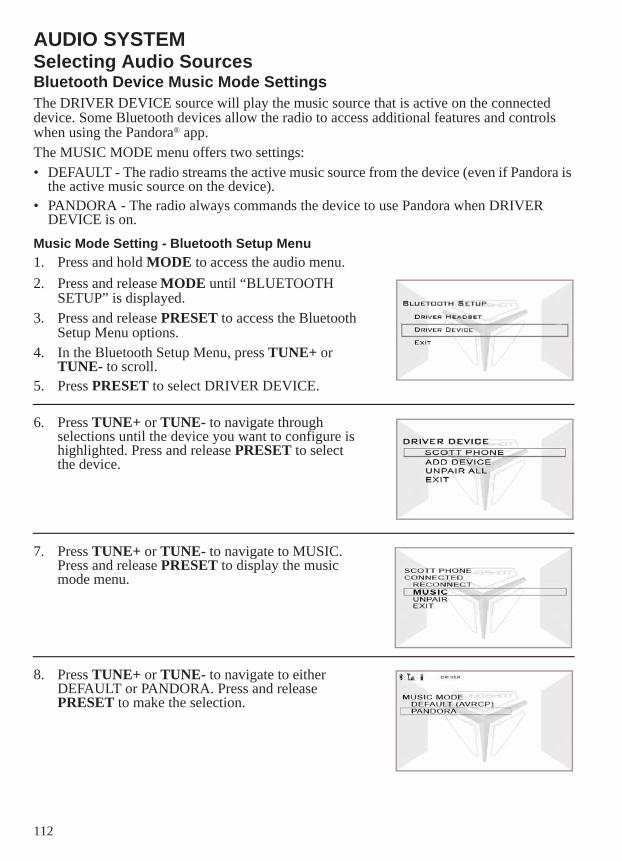
112
AUDIO SYSTEMSelecting Audio SourcesBluetooth Device Music Mode SettingsThe DRIVER DEVICE source will play the music source that is active on the connected device. Some Bluetooth devices allow the radio to access additional features and controls when using the Pandora® app.The MUSIC MODE menu offers two settings:• DEFAULT - The radio streams the active music source from the device (even if Pandora is
the active music source on the device).• PANDORA - The radio always commands the device to use Pandora when DRIVER
DEVICE is on.Music Mode Setting - Bluetooth Setup Menu1. Press and hold MODE to access the audio menu.2. Press and release MODE until “BLUETOOTH
SETUP” is displayed.3. Press and release PRESET to access the Bluetooth
Setup Menu options.4. In the Bluetooth Setup Menu, press TUNE+ or
TUNE- to scroll.5. Press PRESET to select DRIVER DEVICE.
6. Press TUNE+ or TUNE- to navigate through selections until the device you want to configure is highlighted. Press and release PRESET to select the device.
7. Press TUNE+ or TUNE- to navigate to MUSIC. Press and release PRESET to display the music mode menu.
8. Press TUNE+ or TUNE- to navigate to either DEFAULT or PANDORA. Press and release PRESET to make the selection.
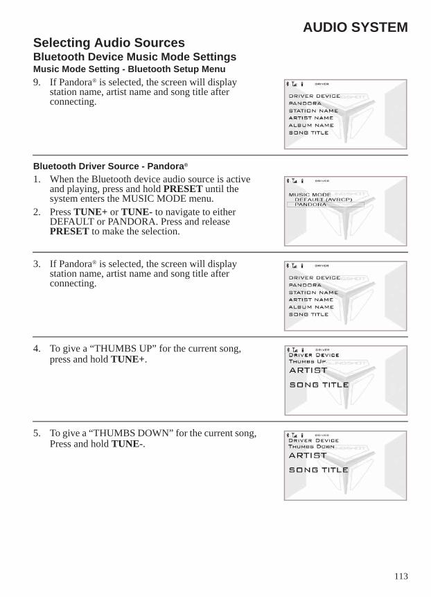
113
AUDIO SYSTEMSelecting Audio SourcesBluetooth Device Music Mode SettingsMusic Mode Setting - Bluetooth Setup Menu9. If Pandora® is selected, the screen will display
station name, artist name and song title after connecting.
Bluetooth Driver Source - Pandora®
1. When the Bluetooth device audio source is active and playing, press and hold PRESET until the system enters the MUSIC MODE menu.
2. Press TUNE+ or TUNE- to navigate to either DEFAULT or PANDORA. Press and release PRESET to make the selection.
3. If Pandora® is selected, the screen will display station name, artist name and song title after connecting.
4. To give a “THUMBS UP” for the current song, press and hold TUNE+.
5. To give a “THUMBS DOWN” for the current song, Press and hold TUNE-.
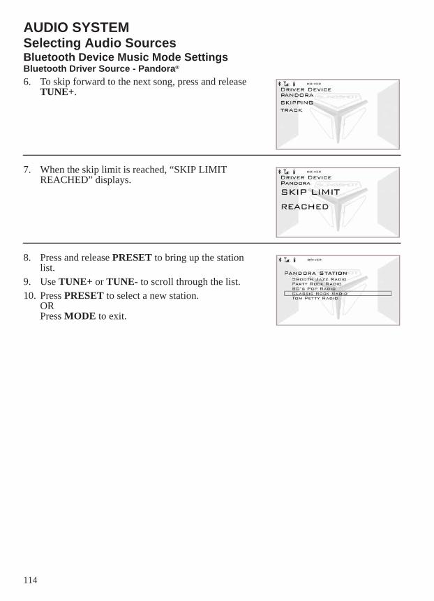
114
AUDIO SYSTEMSelecting Audio SourcesBluetooth Device Music Mode SettingsBluetooth Driver Source - Pandora®
6. To skip forward to the next song, press and release TUNE+.
7. When the skip limit is reached, “SKIP LIMIT REACHED” displays.
8. Press and release PRESET to bring up the station list.
9. Use TUNE+ or TUNE- to scroll through the list. 10. Press PRESET to select a new station.
ORPress MODE to exit.
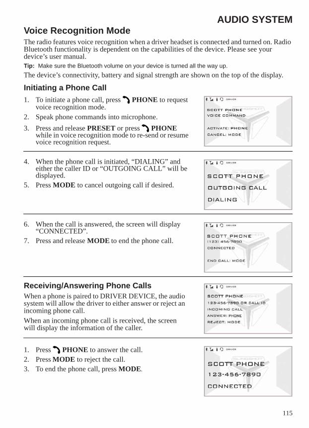
115
AUDIO SYSTEMVoice Recognition ModeThe radio features voice recognition when a driver headset is connected and turned on. Radio Bluetooth functionality is dependent on the capabilities of the device. Please see your device’s user manual.Tip: Make sure the Bluetooth volume on your device is turned all the way up.The device’s connectivity, battery and signal strength are shown on the top of the display.
Initiating a Phone Call1. To initiate a phone call, press PHONE to request
voice recognition mode.2. Speak phone commands into microphone. 3. Press and release PRESET or press PHONE
while in voice recognition mode to re-send or resume voice recognition request.
4. When the phone call is initiated, “DIALING” and either the caller ID or “OUTGOING CALL” will be displayed.
5. Press MODE to cancel outgoing call if desired.
6. When the call is answered, the screen will display “CONNECTED”.
7. Press and release MODE to end the phone call.
Receiving/Answering Phone CallsWhen a phone is paired to DRIVER DEVICE, the audio system will allow the driver to either answer or reject an incoming phone call.When an incoming phone call is received, the screen will display the information of the caller.
1. Press PHONE to answer the call.2. Press MODE to reject the call.3. To end the phone call, press MODE.
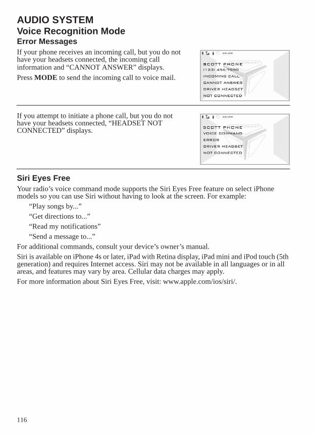
116
AUDIO SYSTEMVoice Recognition ModeError MessagesIf your phone receives an incoming call, but you do not have your headsets connected, the incoming call information and “CANNOT ANSWER” displays.Press MODE to send the incoming call to voice mail.
If you attempt to initiate a phone call, but you do not have your headsets connected, “HEADSET NOT CONNECTED” displays.
Siri Eyes FreeYour radio’s voice command mode supports the Siri Eyes Free feature on select iPhone models so you can use Siri without having to look at the screen. For example:
“Play songs by...”“Get directions to...”“Read my notifications”“Send a message to...”
For additional commands, consult your device’s owner’s manual.Siri is available on iPhone 4s or later, iPad with Retina display, iPad mini and iPod touch (5th generation) and requires Internet access. Siri may not be available in all languages or in all areas, and features may vary by area. Cellular data charges may apply.For more information about Siri Eyes Free, visit: www.apple.com/ios/siri/.
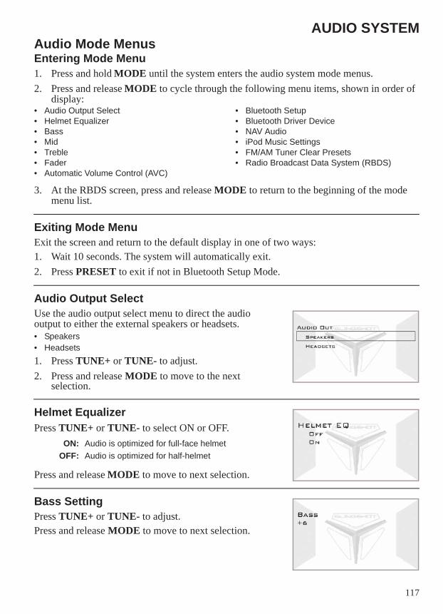
117
AUDIO SYSTEMAudio Mode MenusEntering Mode Menu1. Press and hold MODE until the system enters the audio system mode menus.2. Press and release MODE to cycle through the following menu items, shown in order of
display:• Audio Output Select• Helmet Equalizer• Bass• Mid• Treble• Fader• Automatic Volume Control (AVC)
• Bluetooth Setup• Bluetooth Driver Device• NAV Audio• iPod Music Settings• FM/AM Tuner Clear Presets• Radio Broadcast Data System (RBDS)
3. At the RBDS screen, press and release MODE to return to the beginning of the mode menu list.
Exiting Mode MenuExit the screen and return to the default display in one of two ways:1. Wait 10 seconds. The system will automatically exit.2. Press PRESET to exit if not in Bluetooth Setup Mode.
Audio Output SelectUse the audio output select menu to direct the audio output to either the external speakers or headsets.• Speakers• Headsets1. Press TUNE+ or TUNE- to adjust.2. Press and release MODE to move to the next
selection.
Helmet EqualizerPress TUNE+ or TUNE- to select ON or OFF.
Press and release MODE to move to next selection.
Bass SettingPress TUNE+ or TUNE- to adjust.Press and release MODE to move to next selection.
ON: Audio is optimized for full-face helmetOFF: Audio is optimized for half-helmet
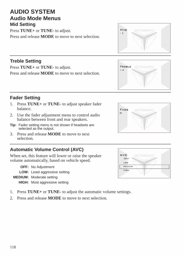
118
AUDIO SYSTEMAudio Mode MenusMid SettingPress TUNE+ or TUNE- to adjust.Press and release MODE to move to next selection.
Treble SettingPress TUNE+ or TUNE- to adjust.Press and release MODE to move to next selection.
Fader Setting1. Press TUNE+ or TUNE- to adjust speaker fader
balance.2. Use the fader adjustment menu to control audio
balance between front and rear speakers.Tip: Fader setting menu is not shown if headsets are
selected as the output.3. Press and release MODE to move to next
selection.
Automatic Volume Control (AVC)When set, this feature will lower or raise the speaker volume automatically, based on vehicle speed.
1. Press TUNE+ or TUNE- to adjust the automatic volume settings.2. Press and release MODE to move to next selection.
OFF: No AdjustmentLOW: Least aggressive setting
MEDIUM: Moderate settingHIGH: Most aggressive setting
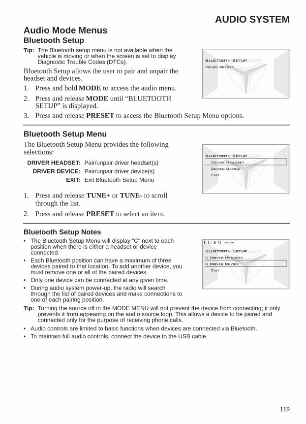
119
AUDIO SYSTEMAudio Mode MenusBluetooth SetupTip: The Bluetooth setup menu is not available when the
vehicle is moving or when the screen is set to display Diagnostic Trouble Codes (DTCs).
Bluetooth Setup allows the user to pair and unpair the headset and devices.1. Press and hold MODE to access the audio menu.2. Press and release MODE until “BLUETOOTH
SETUP” is displayed.3. Press and release PRESET to access the Bluetooth Setup Menu options.
Bluetooth Setup MenuThe Bluetooth Setup Menu provides the following selections:
1. Press and release TUNE+ or TUNE- to scroll through the list.
2. Press and release PRESET to select an item.
Bluetooth Setup Notes• The Bluetooth Setup Menu will display “C” next to each
position when there is either a headset or device connected.
• Each Bluetooth position can have a maximum of three devices paired to that location. To add another device, you must remove one or all of the paired devices.
• Only one device can be connected at any given time.• During audio system power-up, the radio will search
through the list of paired devices and make connections to one of each pairing position.
Tip: Turning the source off in the MODE MENU will not prevent the device from connecting; it only prevents it from appearing on the audio source loop. This allows a device to be paired and connected only for the purpose of receiving phone calls.
• Audio controls are limited to basic functions when devices are connected via Bluetooth.• To maintain full audio controls, connect the device to the USB cable.
DRIVER HEADSET: Pair/unpair driver headset(s)DRIVER DEVICE: Pair/unpair driver device(s)
EXIT: Exit Bluetooth Setup Menu
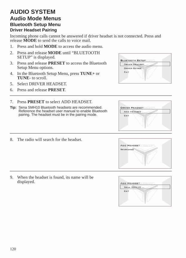
120
AUDIO SYSTEMAudio Mode MenusBluetooth Setup MenuDriver Headset PairingIncoming phone calls cannot be answered if driver headset is not connected. Press and release MODE to send the calls to voice mail.1. Press and hold MODE to access the audio menu.2. Press and release MODE until “BLUETOOTH
SETUP” is displayed.3. Press and release PRESET to access the Bluetooth
Setup Menu options.4. In the Bluetooth Setup Menu, press TUNE+ or
TUNE- to scroll. 5. Select DRIVER HEADSET. 6. Press and release PRESET.
7. Press PRESET to select ADD HEADSET.Tip: Sena SMH10 Bluetooth headsets are recommended.
Reference the headset user manual to enable Bluetooth pairing. The headset must be in the pairing mode.
8. The radio will search for the headset.
9. When the headset is found, its name will be displayed.
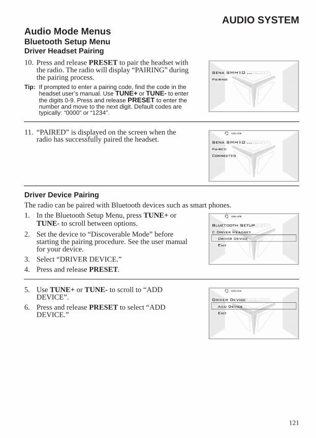
121
AUDIO SYSTEMAudio Mode MenusBluetooth Setup MenuDriver Headset Pairing10. Press and release PRESET to pair the headset with
the radio. The radio will display “PAIRING” during the pairing process.
Tip: If prompted to enter a pairing code, find the code in the headset user’s manual. Use TUNE+ or TUNE- to enter the digits 0-9. Press and release PRESET to enter the number and move to the next digit. Default codes are typically: “0000” or “1234”.
11. “PAIRED” is displayed on the screen when the radio has successfully paired the headset.
Driver Device PairingThe radio can be paired with Bluetooth devices such as smart phones.1. In the Bluetooth Setup Menu, press TUNE+ or
TUNE- to scroll between options.2. Set the device to “Discoverable Mode” before
starting the pairing procedure. See the user manual for your device.
3. Select “DRIVER DEVICE.”4. Press and release PRESET.
5. Use TUNE+ or TUNE- to scroll to “ADD DEVICE”.
6. Press and release PRESET to select “ADD DEVICE.”
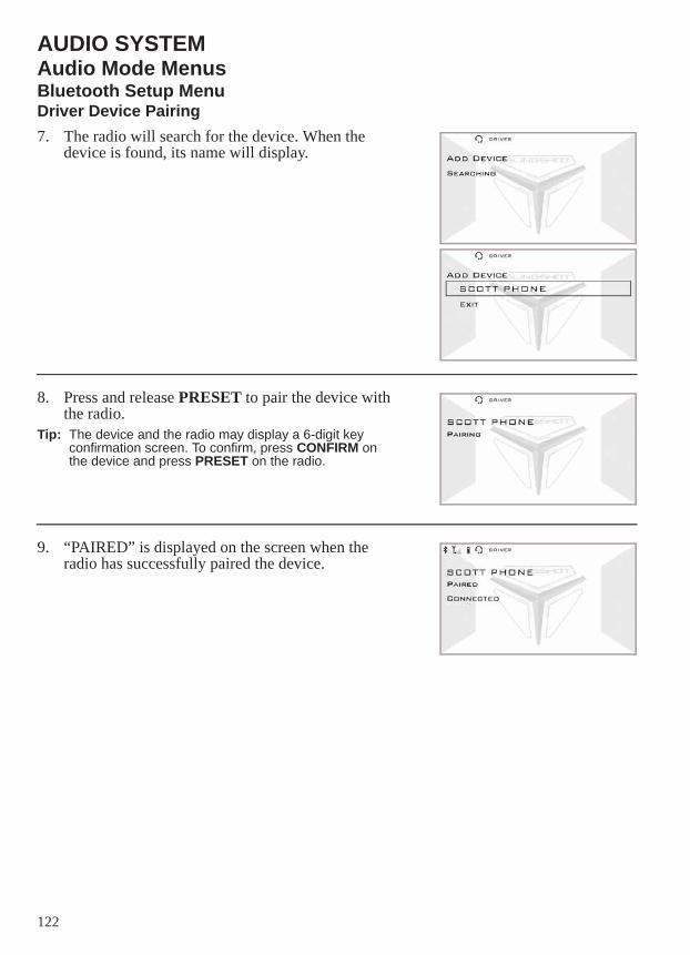
122
AUDIO SYSTEMAudio Mode MenusBluetooth Setup MenuDriver Device Pairing7. The radio will search for the device. When the
device is found, its name will display.
8. Press and release PRESET to pair the device with the radio.
Tip: The device and the radio may display a 6-digit key confirmation screen. To confirm, press CONFIRM on the device and press PRESET on the radio.
9. “PAIRED” is displayed on the screen when the radio has successfully paired the device.
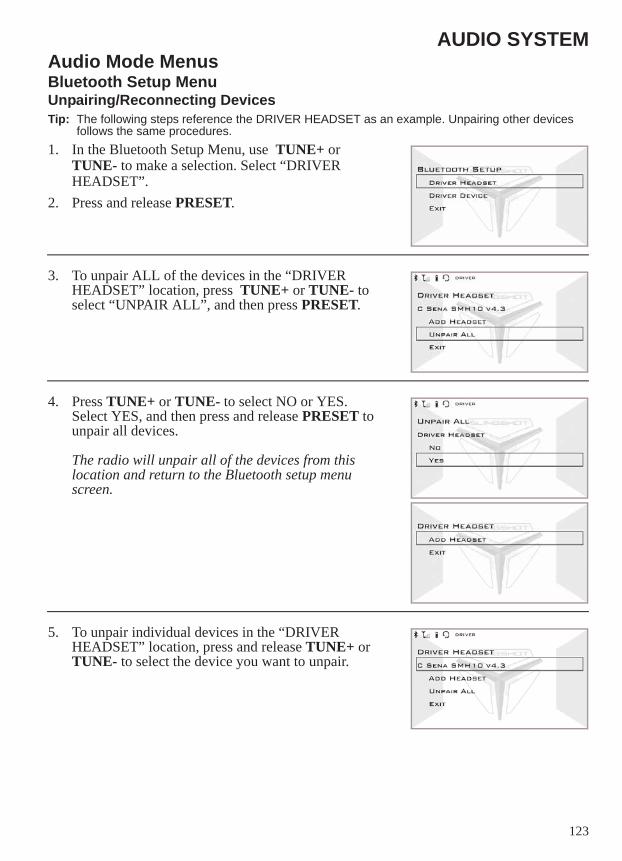
123
AUDIO SYSTEMAudio Mode MenusBluetooth Setup MenuUnpairing/Reconnecting DevicesTip: The following steps reference the DRIVER HEADSET as an example. Unpairing other devices
follows the same procedures.1. In the Bluetooth Setup Menu, use TUNE+ or
TUNE- to make a selection. Select “DRIVER HEADSET”.
2. Press and release PRESET.
3. To unpair ALL of the devices in the “DRIVER HEADSET” location, press TUNE+ or TUNE- to select “UNPAIR ALL”, and then press PRESET.
4. Press TUNE+ or TUNE- to select NO or YES. Select YES, and then press and release PRESET to unpair all devices.
The radio will unpair all of the devices from this location and return to the Bluetooth setup menu screen.
5. To unpair individual devices in the “DRIVER HEADSET” location, press and release TUNE+ or TUNE- to select the device you want to unpair.
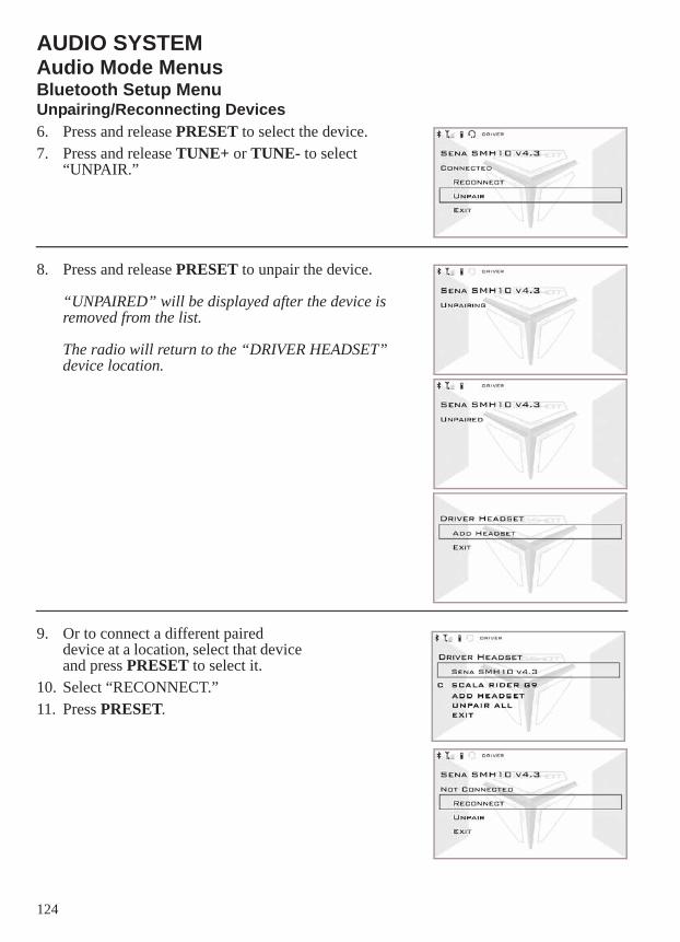
124
AUDIO SYSTEMAudio Mode MenusBluetooth Setup MenuUnpairing/Reconnecting Devices6. Press and release PRESET to select the device.7. Press and release TUNE+ or TUNE- to select
“UNPAIR.”
8. Press and release PRESET to unpair the device.
“UNPAIRED” will be displayed after the device is removed from the list.
The radio will return to the “DRIVER HEADSET” device location.
9. Or to connect a different paired device at a location, select that device and press PRESET to select it.
10. Select “RECONNECT.” 11. Press PRESET.
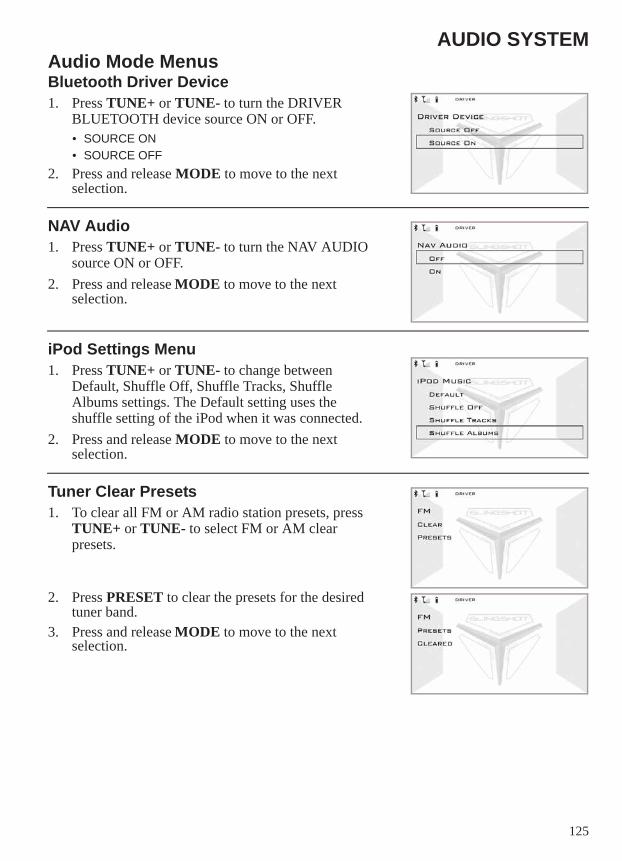
125
AUDIO SYSTEMAudio Mode MenusBluetooth Driver Device1. Press TUNE+ or TUNE- to turn the DRIVER
BLUETOOTH device source ON or OFF.• SOURCE ON• SOURCE OFF
2. Press and release MODE to move to the next selection.
NAV Audio1. Press TUNE+ or TUNE- to turn the NAV AUDIO
source ON or OFF.2. Press and release MODE to move to the next
selection.
iPod Settings Menu1. Press TUNE+ or TUNE- to change between
Default, Shuffle Off, Shuffle Tracks, Shuffle Albums settings. The Default setting uses the shuffle setting of the iPod when it was connected.
2. Press and release MODE to move to the next selection.
Tuner Clear Presets1. To clear all FM or AM radio station presets, press
TUNE+ or TUNE- to select FM or AM clear presets.
2. Press PRESET to clear the presets for the desired tuner band.
3. Press and release MODE to move to the next selection.
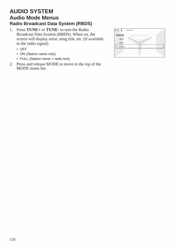
126
AUDIO SYSTEMAudio Mode MenusRadio Broadcast Data System (RBDS)1. Press TUNE+ or TUNE- to turn the Radio
Broadcast Data System (RBDS). When on, the screen will display artist, song title, etc. (if available in the radio signal).• OFF• ON (Station name only)• FULL (Station name + radio text)
2. Press and release MODE to move to the top of the MODE menu list.
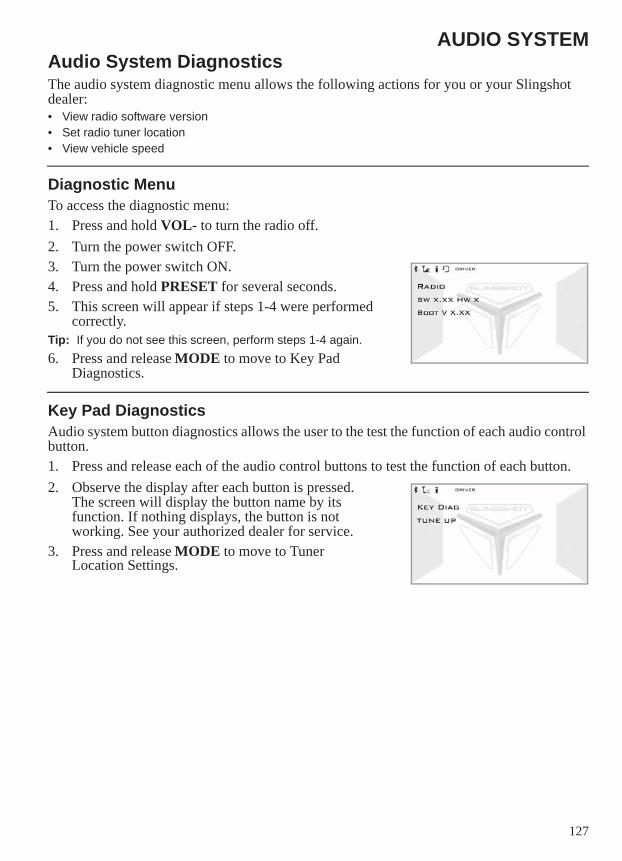
127
AUDIO SYSTEMAudio System DiagnosticsThe audio system diagnostic menu allows the following actions for you or your Slingshot dealer:• View radio software version• Set radio tuner location• View vehicle speed
Diagnostic MenuTo access the diagnostic menu:1. Press and hold VOL- to turn the radio off.2. Turn the power switch OFF.3. Turn the power switch ON.4. Press and hold PRESET for several seconds.5. This screen will appear if steps 1-4 were performed
correctly.Tip: If you do not see this screen, perform steps 1-4 again.6. Press and release MODE to move to Key Pad
Diagnostics.
Key Pad DiagnosticsAudio system button diagnostics allows the user to the test the function of each audio control button.1. Press and release each of the audio control buttons to test the function of each button.2. Observe the display after each button is pressed.
The screen will display the button name by its function. If nothing displays, the button is not working. See your authorized dealer for service.
3. Press and release MODE to move to Tuner Location Settings.
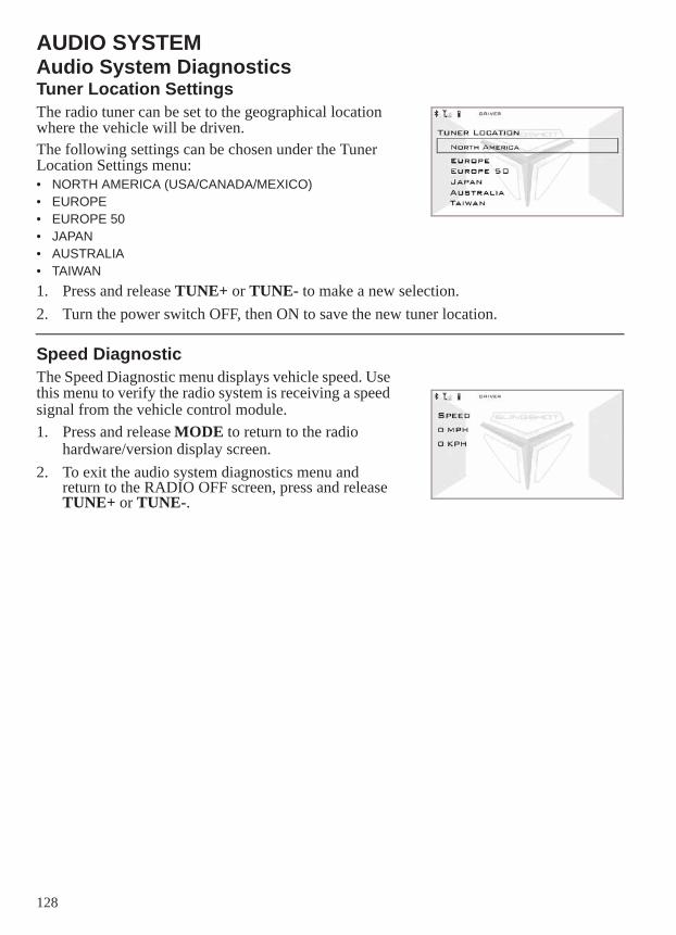
128
AUDIO SYSTEMAudio System DiagnosticsTuner Location SettingsThe radio tuner can be set to the geographical location where the vehicle will be driven.The following settings can be chosen under the Tuner Location Settings menu:• NORTH AMERICA (USA/CANADA/MEXICO)• EUROPE• EUROPE 50• JAPAN• AUSTRALIA• TAIWAN1. Press and release TUNE+ or TUNE- to make a new selection.2. Turn the power switch OFF, then ON to save the new tuner location.
Speed DiagnosticThe Speed Diagnostic menu displays vehicle speed. Use this menu to verify the radio system is receiving a speed signal from the vehicle control module.1. Press and release MODE to return to the radio
hardware/version display screen.2. To exit the audio system diagnostics menu and
return to the RADIO OFF screen, press and release TUNE+ or TUNE-.
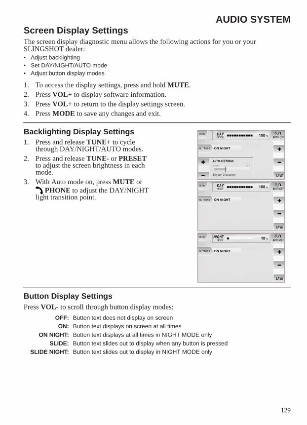
129
AUDIO SYSTEMScreen Display SettingsThe screen display diagnostic menu allows the following actions for you or your SLINGSHOT dealer:• Adjust backlighting• Set DAY/NIGHT/AUTO mode• Adjust button display modes
1. To access the display settings, press and hold MUTE.2. Press VOL+ to display software information.3. Press VOL+ to return to the display settings screen. 4. Press MODE to save any changes and exit.
Backlighting Display Settings1. Press and release TUNE+ to cycle
through DAY/NIGHT/AUTO modes.2. Press and release TUNE- or PRESET
to adjust the screen brightness in each mode.
3. With Auto mode on, press MUTE or PHONE to adjust the DAY/NIGHT
light transition point.
Button Display SettingsPress VOL- to scroll through button display modes:
OFF: Button text does not display on screenON: Button text displays on screen at all times
ON NIGHT: Button text displays at all times in NIGHT MODE onlySLIDE: Button text slides out to display when any button is pressed
SLIDE NIGHT: Button text slides out to display in NIGHT MODE only

130
AUDIO SYSTEMAudio Compliance InformationFCC and Industry Canada Compliance StatementThis equipment complies with FCC radiation exposure limits set forth for an uncontrolled environment. This equipment should be installed and operated with minimum distance of 20 cm between the radiator and your body.This device complies with Industry Canada license-exempt RSS standard(s). Operation is subject to the following two conditions: (1) this device may not cause interference, and (2) this device must accept any interference, including interference that may cause undesired operation of the device.
131
INDEXA
About the Owner’s Manual. . . . . . . . . . . . . . . . . . . 8ABS. . . . . . . . . . . . . . . . . . . . . . . . . . . . . . . . . . . . 28Accelerating . . . . . . . . . . . . . . . . . . . . . . . . . . . . . 44Accessories, How to Choose . . . . . . . . . . . . . . . . 11Air Filter . . . . . . . . . . . . . . . . . . . . . . . . . . . . . . . . 57Angle Drive Fluid . . . . . . . . . . . . . . . . . . . . . . . . . 55Anti-Lock Brake System . . . . . . . . . . . . . . . . . . . 28Audio Switches . . . . . . . . . . . . . . . . . . . . . . . . . . . 20Audio System. . . . . . . . . . . . . . . . . . . . . . . . . . . . 33
Audio Mode Menus . . . . . . . . . . . . . . 117-126Audio Source Selection . . . . . . . . . . . 102-114Compliance Information . . . . . . . . . . . . . . 130Diagnostics. . . . . . . . . . . . . . . . . . . . . 127-128Introduction . . . . . . . . . . . . . . . . . . . . . 98-100Low Voltage Mute . . . . . . . . . . . . . . . . . . . 102Mute . . . . . . . . . . . . . . . . . . . . . . . . . . . . . . 102Phone . . . . . . . . . . . . . . . . . . . . . . . . . . . . . 102Power and Volume Controls . . . . . . . . . . . 101Screen Display Settings . . . . . . . . . . . . . . . 129Voice Recognition Mode . . . . . . . . . . 115-116
BBack-Up Camera (if equipped). . . . . . . . . . . . . . . 33Battery
Access Panel . . . . . . . . . . . . . . . . . . . . . . . . 70Battery Safety. . . . . . . . . . . . . . . . . . . . . 69-70Charging. . . . . . . . . . . . . . . . . . . . . . . . . . . . 72Installation . . . . . . . . . . . . . . . . . . . . . . . . . . 71Maintenance . . . . . . . . . . . . . . . . . . . . . . . . . 69Removal . . . . . . . . . . . . . . . . . . . . . . . . . . . . 70Storage . . . . . . . . . . . . . . . . . . . . . . . . . . 71, 80
Brake Fluid . . . . . . . . . . . . . . . . . . . . . . . . . . . 62-63Brake Fluid Change . . . . . . . . . . . . . . . . . . . . . . . 62Brake Fluid Precautions . . . . . . . . . . . . . . . . . . . . 62Brake Lever, Park . . . . . . . . . . . . . . . . . . . . . . . . . 29Brake Pedal . . . . . . . . . . . . . . . . . . . . . . . . . . . . . . 27Brake System Inspections . . . . . . . . . . . . . . . . . . . 64Brakes . . . . . . . . . . . . . . . . . . . . . . . . . . . . . . . . . . 28Braking . . . . . . . . . . . . . . . . . . . . . . . . . . . . . . . . . 44Break-In Maintenance. . . . . . . . . . . . . . . . . . . . . . 48Break-In Period. . . . . . . . . . . . . . . . . . . . . . . . . . . 40Breather Hose Inspection . . . . . . . . . . . . . . . . . . . 59
CCheck Engine Indicator . . . . . . . . . . . . . . . . . . . . 26Cleaning Products . . . . . . . . . . . . . . . . . . . . . . . . . 78Clutch Fluid, Hydraulic . . . . . . . . . . . . . . . . . 60-61Clutch Pedal . . . . . . . . . . . . . . . . . . . . . . . . . . . . . 27Compliance, Vehicle. . . . . . . . . . . . . . . . . . . . . . . 13Component Locations . . . . . . . . . . . . . . . . . . . . . . 17Console Components . . . . . . . . . . . . . . . . . . . 18-21Coolant . . . . . . . . . . . . . . . . . . . . . . . . . . . . . . . . . 56Coolant Hoses Inspection . . . . . . . . . . . . . . . . . . . 57Coolant Level . . . . . . . . . . . . . . . . . . . . . . . . . . . . 56Cooling Fan. . . . . . . . . . . . . . . . . . . . . . . . . . . . . . 57Cooling System Operation . . . . . . . . . . . . . . . 56-57Cruise Control Operation . . . . . . . . . . . . . . . . 46-47Cruise Control Switches . . . . . . . . . . . . . . . . . . . . 19
DDisplay Units, Standard/Metric . . . . . . . . . . . . . . 25Drive Belt
Cleaning . . . . . . . . . . . . . . . . . . . . . . . . . . . . 58Condition . . . . . . . . . . . . . . . . . . . . . . . . . . . 58Wear Analysis . . . . . . . . . . . . . . . . . . . . . . . 58
Drive Belt Inspection . . . . . . . . . . . . . . . . . . . . . . 38Drivetrain Break-In. . . . . . . . . . . . . . . . . . . . . . . . 40Driving Safety. . . . . . . . . . . . . . . . . . . . . . . . . . 9-11
EElectronic Power-Assisted Steering . . . . . . . . . . . 27Electronic Stability Program (ESP) Switch . . . . . 21Elevating the Vehicle for Service . . . . . . . . . . . . . 49Engine Break-In . . . . . . . . . . . . . . . . . . . . . . . . . . 40Engine Compression Test . . . . . . . . . . . . . . . . . . . 68Engine Identification Number . . . . . . . . . . . . . . . 16Engine Oil . . . . . . . . . . . . . . . . . . . . . . . . . . . . 52-53Engine, Starting . . . . . . . . . . . . . . . . . . . . . . . . . . 42Engine, Stopping. . . . . . . . . . . . . . . . . . . . . . . . . . 45EPAS. . . . . . . . . . . . . . . . . . . . . . . . . . . . . . . . . . . 27Equipment Modifications . . . . . . . . . . . . . . . . . . . 11Error Codes, Engine . . . . . . . . . . . . . . . . . . . . . . . 26Evaporative Emission Control System (CaliforniaModels) . . . . . . . . . . . . . . . . . . . . . . . . . . . . . . . . . 59Exhaust Safety . . . . . . . . . . . . . . . . . . . . . . . . . . . 12Exhaust System Inspection . . . . . . . . . . . . . . . . . . 68
FFan, Cooling . . . . . . . . . . . . . . . . . . . . . . . . . . . . . 57Fastener Inspection . . . . . . . . . . . . . . . . . . . . . . . . 38Fluid Change
Angle Drive . . . . . . . . . . . . . . . . . . . . . . . . . 55Brake Fluid. . . . . . . . . . . . . . . . . . . . . . . . . . 62Hydraulic Clutch Fluid . . . . . . . . . . . . . . . . 61Transmission . . . . . . . . . . . . . . . . . . . . . . . . 54
Fluid Change, Engine Oil . . . . . . . . . . . . . . . . . . . 53Fluid Level
Angle Drive . . . . . . . . . . . . . . . . . . . . . . . . . 55Brake Fluid. . . . . . . . . . . . . . . . . . . . . . . . . . 63Hydraulic Clutch Fluid . . . . . . . . . . . . . . . . 60Transmission . . . . . . . . . . . . . . . . . . . . . . . . 54
Fluid Level, Engine Oil . . . . . . . . . . . . . . . . . . . . 52Fluid, Engine Oil . . . . . . . . . . . . . . . . . . . . . . 52-53Foot Controls (Foot Pedals) . . . . . . . . . . . . . . . . . 27Fuel Cap . . . . . . . . . . . . . . . . . . . . . . . . . . . . . . . . 31Fuel Handling Safety . . . . . . . . . . . . . . . . . . . . . . 12Fuel Level . . . . . . . . . . . . . . . . . . . . . . . . . . . . . . . 38Fuel Recommendation . . . . . . . . . . . . . . . . . . . . . 41Fuel System Inspection. . . . . . . . . . . . . . . . . . . . . 59Fuel System, Priming . . . . . . . . . . . . . . . . . . . . . . 41Fuel Tank Filler Cap. . . . . . . . . . . . . . . . . . . . . . . 31Fuse Replacement . . . . . . . . . . . . . . . . . . . . . . . . . 77
132
INDEXG
Gasoline Handling Safety . . . . . . . . . . . . . . . . . . 12Gear Shifting . . . . . . . . . . . . . . . . . . . . . . . . . . 43-44Glove Box Storage. . . . . . . . . . . . . . . . . . . . . . . . 33Gross Vehicle Weight Rating . . . . . . . . . . . . . . . 14GVWR . . . . . . . . . . . . . . . . . . . . . . . . . . . . . . . . . 14
HHazard Switch/Emergency Flashers . . . . . . . . . . 20Headlamp Aim Adjustment (Canada) . . . . . . . . . 76Headlamp Aim Adjustment (USA) . . . . . . . . . 74-75Headlamp Aim Inspection Conditions. . . . . . . . . 74Headlamp Bulb Replacement . . . . . . . . . . . . . . . 73Headlight High/Low Beam Switch . . . . . . . . . . . 19Hood, Opening/Closing . . . . . . . . . . . . . . . . . . . . 31Horn . . . . . . . . . . . . . . . . . . . . . . . . . . . . . . . . . . . 18
IIdentification Number Record . . . . . . . . . . . . . . . . 6Ignition Key Number. . . . . . . . . . . . . . . . . . . . . . 16Ignition Switch. . . . . . . . . . . . . . . . . . . . . . . . . . . 18Indicator Lamps . . . . . . . . . . . . . . . . . . . . . . . . 22-23Information Labels. . . . . . . . . . . . . . . . . . . . . . . . 15Instrument Cluster . . . . . . . . . . . . . . . . . . . . . 19, 22
KKey Number. . . . . . . . . . . . . . . . . . . . . . . . . . . . . 16
LLabels, Information . . . . . . . . . . . . . . . . . . . . . . . 15Labels, Safety . . . . . . . . . . . . . . . . . . . . . . . . . . . 15LED Light Assemblies . . . . . . . . . . . . . . . . . . . . 73Lights
Headlamp Aim Adjustment (Canada). . . . . 76Headlamp Aim Adjustment (USA). . . . 74-75Headlamp Bulb Replacement . . . . . . . . . . . 73LED Light Assemblies . . . . . . . . . . . . . . . . 73
MMaintenance
Break-In Maintenance. . . . . . . . . . . . . . . . . 48Major Maintenance . . . . . . . . . . . . . . . . . . . 48Periodic Maintenance . . . . . . . . . . . . . . 50-51
Maintenance for Safety . . . . . . . . . . . . . . . . . . . . 13Maintenance Log . . . . . . . . . . . . . . . . . . . . . . . . . 97Maintenance Safety . . . . . . . . . . . . . . . . . . . . . . . 49Maintenance, Required . . . . . . . . . . . . . . . . . . . . 13Major Maintenance . . . . . . . . . . . . . . . . . . . . . . . 48Master Lighting Switch (Canada) . . . . . . . . . . . . 20Metric Display . . . . . . . . . . . . . . . . . . . . . . . . . . . 25MFD. . . . . . . . . . . . . . . . . . . . . . . . . . . . . . . . . 24-26Mirror Adjustment . . . . . . . . . . . . . . . . . . . . . . . . 33Mode Button . . . . . . . . . . . . . . . . . . . . . . . . . . . . 21Modifications, Vehicle . . . . . . . . . . . . . . . . . . . . 11Multi-Function Display . . . . . . . . . . . . . . . . . . 24-26
OOil Change, Engine Oil/Filter . . . . . . . . . . . . . . . . 53Oil Level, Engine Oil . . . . . . . . . . . . . . . . . . . . . . 52Oil, Engine. . . . . . . . . . . . . . . . . . . . . . . . . . . . 52-53Operation, Cooling System . . . . . . . . . . . . . . . 56-57
PPark Brake Lever . . . . . . . . . . . . . . . . . . . . . . . . . . 29Parking the Vehicle . . . . . . . . . . . . . . . . . . . . . . . . 11Periodic Maintenance . . . . . . . . . . . . . . . . . . . 50-51Power-Assisted Steering . . . . . . . . . . . . . . . . . . . . 27
RRadiator . . . . . . . . . . . . . . . . . . . . . . . . . . . . . . . . . 57Radio . . . . . . . . . . . . . . . . . . . . . . . . . . . . . . . . . . . 33Refueling Safety . . . . . . . . . . . . . . . . . . . . . . . . . . 12Registration, Warranty . . . . . . . . . . . . . . . . . . . . . 87Reverse Operation . . . . . . . . . . . . . . . . . . . . . . . . . 45
SSafety Defects, Reporting to NHTSA . . . . . . . . . . 14Safety Labels . . . . . . . . . . . . . . . . . . . . . . . . . . . . . 15Safety Symbols . . . . . . . . . . . . . . . . . . . . . . . . . . . . 8Safety While Servicing . . . . . . . . . . . . . . . . . . . . . 49Seat Adjustments . . . . . . . . . . . . . . . . . . . . . . . . . . 30Seat Belt Inspection . . . . . . . . . . . . . . . . . . . . . . . . 32Seat Belts . . . . . . . . . . . . . . . . . . . . . . . . . . . . . . . . 32Security System (Canada) . . . . . . . . . . . . . . . . 34-35Service Manual . . . . . . . . . . . . . . . . . . . . . . . . . . . 86Service Procedure Safety. . . . . . . . . . . . . . . . . . . . 49Severe Use Definition . . . . . . . . . . . . . . . . . . . . . . 50Shift Points . . . . . . . . . . . . . . . . . . . . . . . . . . . . . . 44Shifting Gears . . . . . . . . . . . . . . . . . . . . . . . . . 43-44Signal Words . . . . . . . . . . . . . . . . . . . . . . . . . . . . . . 8SLINGSHOT Operating Characteristics . . . . . . . . 39Spark Plug Recommendations. . . . . . . . . . . . . . . . 67Spark Plug Service . . . . . . . . . . . . . . . . . . . . . 67-68Spark Plugs . . . . . . . . . . . . . . . . . . . . . . . . . . . 67-68Speedometer . . . . . . . . . . . . . . . . . . . . . . . . . . . . . 22Starter Interlock Switch . . . . . . . . . . . . . . . . . . . . . 27Starter Switch . . . . . . . . . . . . . . . . . . . . . . . . . . . . 20Steering Inspection . . . . . . . . . . . . . . . . . . . . . . . . 38Steering Wheel Adjustments . . . . . . . . . . . . . . . . . 30Storage
Battery Care . . . . . . . . . . . . . . . . . . . . . . . . 80Removal From . . . . . . . . . . . . . . . . . . . . . . 80Seasonal . . . . . . . . . . . . . . . . . . . . . . . . . . . 79
Storage Compartments . . . . . . . . . . . . . . . . . . . . . 33Suspension Inspection, Front. . . . . . . . . . . . . . . . . 38Suspension Inspection, Rear . . . . . . . . . . . . . . . . . 38Suspension Inspections . . . . . . . . . . . . . . . . . . . . . 59
133
INDEXS
SwitchesAudio Switches . . . . . . . . . . . . . . . . . . . . . . 20Cruise Control Switches. . . . . . . . . . . . . . . . 19Electronic Stability Program (ESP) Switch . 21Emergency Flashers . . . . . . . . . . . . . . . . . . . 20Hazard Switch . . . . . . . . . . . . . . . . . . . . . . . 20Headlight High/Low Beam Switch . . . . . . . 19Ignition Switch. . . . . . . . . . . . . . . . . . . . . . . 18Master Lighting Switch (Canada) . . . . . . . . 20Mode Button . . . . . . . . . . . . . . . . . . . . . . . . 21Starter Interlock Switch . . . . . . . . . . . . . . . . 27Starter Switch. . . . . . . . . . . . . . . . . . . . . . . . 20Turn Signal Lever . . . . . . . . . . . . . . . . . . . . 19
TTachometer . . . . . . . . . . . . . . . . . . . . . . . . . . . . . . 22Throttle Pedal . . . . . . . . . . . . . . . . . . . . . . . . . . . . 27Tilt Steering . . . . . . . . . . . . . . . . . . . . . . . . . . . . . 30Tires . . . . . . . . . . . . . . . . . . . . . . . . . . . . . . . . 65-66
Tire Condition . . . . . . . . . . . . . . . . . . . . . . . 65Tire Pressure . . . . . . . . . . . . . . . . . . . . . . . . 65Tread Depth . . . . . . . . . . . . . . . . . . . . . . . . . 65
Transmission Fluid . . . . . . . . . . . . . . . . . . . . . . . . 54Transporting the SLINGSHOT. . . . . . . . . . . . . . . 81Turn Signal Lever . . . . . . . . . . . . . . . . . . . . . . . . . 19
WWashing the Vehicle. . . . . . . . . . . . . . . . . . . . . . . 78Weight Capacity . . . . . . . . . . . . . . . . . . . . . . . . . . 14Wheels
Wheel Inspection . . . . . . . . . . . . . . . . . . . . . 66Wheel Installation . . . . . . . . . . . . . . . . . . . . 66Wheel Removal . . . . . . . . . . . . . . . . . . . . . . 66
Wheels and Tires . . . . . . . . . . . . . . . . . . . . . . 65-66Windshield (if equipped) . . . . . . . . . . . . . . . . . . . 31Windshield Care (if equipped) . . . . . . . . . . . . . . . 31
To locate your nearest dealer, call 1-800-POLARIS (765-2747)or visit www.polaris.com
Polaris Industries Inc. 2100 Highway 55Medina, MN 55340
Part No. 9926666 Rev 01Printed in USA
READ OWNER’S MANUALWATCH SAFETY VIDEO