OWNER’S MANUAL - DYE Paintballdyepaintball.com/wp-content/uploads/2016/09/Rize-Manual-web.pdf ·...
16
D Y E P A I N T B A L L . C O M O W N E R ’ S M A N U A L DYE Precision, Inc. USA 10637 Scripps Summit Ct. San Diego, CA 92131 P 858-536-5183 F 858-536-5191 GERMANY Albert Einstein Str. 2 B 77656 Offenburg, Germany P +49 (0)781 639 349 91 ASIA No. 253, Guojhong Rd., Dali Dist. Taichung City 412, Taiwan (R.O.C.) P +886 (0) 4-2407-9135 F +886 (0) 4-2407-2090 dyepaintball.com Copyright ©2016 DYE Precision, Inc. The stylized “proto” logo, the “P” logo, and RIZE logo are either registered trademarks, trademarks, or design trademarks of DYE Precision, Inc. DYE Precision, Inc. U.S. Patent # 5,613,483, 7,594,503; 7,765,998. OTHER U.S. AND INT’L PATENTS PENDING. Covered by one or more of the following U.S. Patents, 5,613,483; 5,881,707; 5,967,133; 6,035,843 and 6,474,326. For a complete list of patents visit www.dyeprecision.com/patents Made in Taiwan
Transcript of OWNER’S MANUAL - DYE Paintballdyepaintball.com/wp-content/uploads/2016/09/Rize-Manual-web.pdf ·...

D Y E P A I N T b A L L . C O M
O W N E R ’ S M A N U A L
dYe Precision, Inc.USA 10637 Scripps Summit Ct. San Diego, CA 92131
P 858-536-5183 f 858-536-5191
GERMANY Albert Einstein Str. 2 B77656 Offenburg, Germany
P +49 (0)781 639 349 91
ASIA No. 253, Guojhong Rd., Dali Dist.Taichung City 412, Taiwan (R.O.C.)
P +886 (0) 4-2407-9135 f +886 (0) 4-2407-2090dyepaintball.com
Copyright ©2016 DYE Precision, In c. The stylized “proto” logo, the “P” logo, and RIZE logo areeither registered trademarks, trademarks, or design trademarks of DYE Precision, Inc.
DYE Precision, Inc. U.S. Patent # 5,613,483, 7,594,503; 7,765,998. OTHER U.S. AND INT’L PATENTS PENDING.Covered by one or more of the following U.S. Patents, 5,613,483; 5,881,707; 5,967,133; 6,035,843 and 6,474,326.
For a complete list of patents visit www.dyeprecision.com/patentsMade in Taiwan

W W W . D Y E P A I N T B A L L . C O M 1
TAbLE OF CONTENTS
- IMPORTANT SAFETY INSTRUCTIONS AND GUIDELINES ......................................................... PAGE 02
- QUICk START UP GUIDE ............................................................................................................... PAGE 04
- RIZE™ bOARD SETTINGS AND FUNCTIONS .............................................................................. PAGE 06
- TRIGGER ADjUSTMENTS ............................................................................................................. PAGE 13
- RIZE™ bOLT ASSEMbLY AND MAINTENANCE ......................................................................... PAGE 14
- RIZE™ bOLT O-RING LIST ............................................................................................................. PAGE 17
- FEED NECk ADjUSTMENT ........................................................................................................... PAGE 18
- hYPER3™ REGULATOR ADjUSTMENT AND MAINTENANCE .................................................. PAGE 20
- vELOCITY ADjUSTMENT .............................................................................................................. PAGE 20
- ANTI ChOP EYES AND bALL DETENTS ....................................................................................... PAGE 22
- AIRPORT ADjUSTMENTS ............................................................................................................ PAGE 24
- TROUbLE ShOOTING .................................................................................................................... PAGE 25
- ExPLODED vIEW ............................................................................................................................ PAGE 28
- WARRANTY AND LEGAL INFORMATION .................................................................................... PAGE 29
D Y E P A I N T B A L L . C O M
R I Z E ™ O W N E R ’ S M A N U A L
INCLUDED WITh YOUR RIZE™
RIZE™ Marker1 pc Proto BarrelAllen tool set including 0.05”, 1/16”, 5/64”, 3/32”, 1/8”, 5/32”, 3/16” and 1/4”.1/4 oz. DYE Slick Lube™Parts KitBarrel CoverOwner’s ManualWarranty Card9V Battery
The RIZE™ comes with the tools required to perform general maintenance and setting up.
For a complete service the following tools are required:C-clip pliers#0 Phillips head screw driverA sharp pick to remove O-rings

w w w . d y e p a i n t b a l l . c o mw w w . d y e p a i n t b a l l . c o m2 3
• Compressedgasisdangerous,donotallowcompressedgasto come in contact with your skin or try to stop a leak by covering it with your hand.• AlwaysfitabarrelblockingdevicetoyourRIZE™ when not in use on thefieldofplay.• Theowner’smanualandanyrelatedwarningsorinstructionsshould always accompany the product for reference or in the event of resale and new ownership.• DonotpointtheRIZE™ marker at anything that you do not intend to shoot.• Donotshootatpeople,animals,houses,carsoranythingnotrelated to the sport of paintball.• DonotfiretheRIZE™ without the bolt screwed in completely.• Ifyoureadtheseinstructionsanddonotfullyunderstandthemorare unsure of your ability to make necessary adjustments properly, call DYE Precision or your local pro shop for help.
• The RIZE™ marker is not a toy. Misuse may cause serious injury or death.• Pleaseread,understandandfollowthedirectionsintheRIZE™ owner’s manual.• Eyeprotectionthatisdesignedspecificallyforpaintballandmeets ASTM/CE standards must be worn by user and persons within range.• Recommend18yearsoroldertopurchase.Personunder18must have adult supervision.• AlwaystreattheRIZE™markerasifitwereloadedandabletofire.• Donotexceed850psiinputpressure.• Onlyuse.68caliberpaintballsthatmeetASTM/CEstandards.• Ensureallairlinesandfittingsaretightenedandsecuredbefore gassing up the RIZE™.• AlwayschronographtheRIZE™ marker before playing paintball.• NevershoottheRIZE™markeratvelocitiesinexcessof300feet per second, or at velocities greater than local or national laws allow.• NeverlookintothebarrelorbreechareaoftheRIZE™ when the markerisswitchedonandabletofire.
W A R N I N GIMPORTANT SAFETY INSTRUCTIONS AND GUIDELINES
W A R N I N GIMPORTANT SAFETY INSTRUCTIONS AND GUIDELINES

w w w . d y e p a i n t b a l l . c o mw w w . d y e p a i n t b a l l . c o m4 5
STEP 4. ATTAChING GAS SOURCE
Screw on a preset air system into the airport located on the bootom of the grip frame.
Be sure the air system is screwed in all the way into the Airport. If there is a leak from the
airport when screwing in the air system, replace the o-ring on the preset regulator.
When screwing the air system into the airport, always check that the threads on the air
system and the airport are clean and not worn out. If you think the threads are not in good
condition, contact DYE Precision or a professional store before screwing in the air system.
TheRIZE™airportwillworkwithboth3000psi,4500psiairsystemsandCO2tanksfitted
with an anti-siphon.
STEP 5. TURNING ON ThE RIZE™ AND ChECkING ThE vELOCITY
A. Make sure you and everybody around you is wearing ASTM / CE approved paintball
masks.
B. Press and hold the top button located behind the grip frame until the RIZE™ turns on.
WARNING, ThE RIZE™ IS LIvE. MAkE SURE bARREL PLUG IS IN PLACE AND DO NOT
POINT ThE RIZE™ AT ANYThING YOU DON’T INTEND TO ShOOT.
C. Fill up the loader with .68 caliber paintballs.
D. Shoot the RIZE™ over a chronograph to check the velocity. If adjustment is needed,
adjust the velocity by turning the Hyper3™ velocity adjustment screw with a 3/16” Allen
key. In (clockwise) will reduce the velocity and out (counter clockwise) will increase the
velocity. After each adjustment it takes a few shots before the change can be seen on the
chronograph.NeveradjusttheRIZE™toshootfasterthan300fpsorwhatthefieldrules/
local laws permit.
QUICk REFERENCEUSING YOUR MARkER
QUICk REFERENCEUSING YOUR MARkER
QUICk START UP GUIDEbefore playing with your new RIZE™ paintball marker there are a few important
steps to take.
STEP 1. bATTERY INSTALLATION
A. Remove three right hand side grip panel screws with a 3/32” Allen key.
B. Open grip panel and install 9V battery into the connector inside the frame. Start by
inserting the top of the battery into the recess and aligning the battery terminals with the
contacts on the board, then pushing the bottom of the battery fully into place. Ensure
that the battery removal ribbon leaves a small tail accessible from under battery when
installed to aid for easy battery removal. Note the markings above the battery housing
which indicate which of the board contacts are positive and negative and install the
battery accordingly.
C. Close grip panel and tighten the three screws back. While closing the panel
observe that no wires get caught between the frame and the grip panel.
STEP 2. bARREL INSTALLATION
A. Screw on the barrel to the front of the RIZE™. Make sure it threads all the way
in and is secure.
B. Attach the barrel plug so that it covers the tip of the barrel and secure
the gun.
STEP 3. LOADER INSTALLATION
Tighten your loader into the adjustable feedneck using a 5/32” Allen key.
For best performance, use a force feeding motorized loader, preferably
the Rotor™ Loader.
w w w . d y e p a i n t b a l l . c o mw w w . d y e p a i n t b a l l . c o m6 7
RIZE™ bOARDSETTINGS AND FUNCTIONS
RIZE™ bOARDSETTINGS AND FUNCTIONS
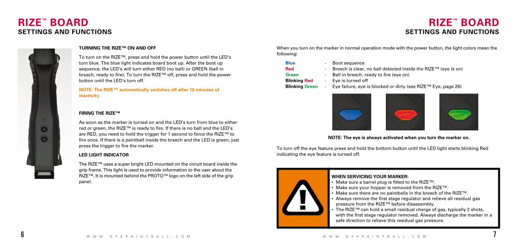
TURNING ThE RIZE™ ON AND OFF
To turn on the RIZE™, press and hold the power button until the LED’s turn blue. The blue light indicates board boot up. After the boot up sequence, the LED’s will turn either RED (no ball) or GREEN (ball in breach,readytofire).ToturntheRIZE™off,pressandholdthepowerbutton until the LED’s turn off.
NOTE: The RIZE™ automatically switches off after 10 minutes of inactivity.
FIRING ThE RIZE™
As soon as the marker is turned on and the LED’s turn from blue to either redorgreen,theRIZE™isreadytofire.IfthereisnoballandtheLED’sare RED, you need to hold the trigger for 1 second to force the RIZE™ to fireonce.IfthereisapaintballinsidethebreechandtheLEDisgreen,justpressthetriggertofirethemarker.
LED LIGhT INDICATOR
The RIZE™ uses a super bright LED mounted on the circuit board inside the grip frame. This light is used to provide information to the user about the RIZE™. It is mounted behind the PROTO™ logo on the left side of the grip panel.
When you turn on the marker in normal operation mode with the power button, the light colors mean the following:
blue - Boot sequence Red - Breech is clear, no ball detected inside the RIZE™ (eye is on) Green - Ballinbreech,readytofire(eyeon) blinking Red - Eye is turned off blinking Green - Eye failure, eye is blocked or dirty (see RIZE™ Eye, page 26)
To turn off the eye feature press and hold the bottom button until the LED light starts blinking Red indicating the eye feature is turned off.
NOTE: The eye is always activated when you turn the marker on.
WhEN SERvICING YOUR MARkER:• MakesureabarrelplugisfittedtotheRIZE™.• MakesureyourhopperisremovedfromtheRIZE™.• MakesuretherearenopaintballsinthebreechoftheRIZE™.• Alwaysremovethefirststageregulatorandrelieveallresidualgas pressure from the RIZE™ before disassembly. • TheRIZE™canholdasmallresidualchargeofgas,typically2shots, withthefirststageregulatorremoved.Alwaysdischargethemarkerina safe direction to relieve this residual gas pressure.

w w w . d y e p a i n t b a l l . c o mw w w . d y e p a i n t b a l l . c o m8 9
RIZE™ bOARDSETTINGS AND FUNCTIONS
bOARD SETTINGS AND CONFIGURATION MODE
TherearefivesettingsyoucanalterontheRIZE™boardwiththeDIPswitchesinsidethegripframe(seefigure1):
AbS Anti Bolt Stick. Trigger Sensitivity This setting adjusts the delay between two trigger pulls. Dwell This is the time the solenoid is activated for. Rate Of Fire This setting is for adjusting the maximumrateoffire Firing Mode ThisisthefiringmodetheRIZE™uses.
TherearetwoDIPswitchesmountedontheboardoftheRIZE™(Seefigure1).ThefirstoneisusedfortheABSsettingandthesecondoneisusedtoaccessaconfigurationmodewhichchangestheotherfour settings.
Anti bolt Stick - When ABS is activated, the dwell is increased after 15secondsofinactivityforthenextshotfired.Thishelpstopreventbolt-stick,butmayresultinhighervelocityforthefirstshot.
FIGURE 1
ABS ON(defAult)
ABS Off
CONFIGURATION MODE - The following settings can only be modifiedinconfigurationmode.Toactivatetheconfigurationmode, turn your marker off and set DIP switch 2 to the ON position.Next,turnyourmarkeron.TheLED’scyclethroughall colors for one second to indicate that you have entered theconfigurationmode.
To cycle through different settings, pull and release the trigger. Configurationmodehas4settingsthatcanbechanged.
TO ChANGE A vALUE OF A SETTING
1.Whileintheconfigurationmode,choosethesettingyouwishtochangebypullingthetriggertocycle through different options. 2. When the LED indicates the color of the setting you wish to change, pull and hold the trigger until the LED starts to flash. 3. The LED will flash as many times as the previous setting was and it will then turn off. Now pull the trigger as many times as you wish the new setting to be. Note: You must enter a value at this point, if you do not wish to alter the setting then re-enter the previous value.4. When done, the LED will cycle through all the colors again to indicate setting was saved and turn backtogreen.Youcannowchangeanothersettingorquittheconfigurationmode.5.Toexitconfigurationmode,setDIP2totheoffposition.
NORmAl mOde
CONfIGuRAtION mOde
RIZE™ bOARDSETTINGS AND FUNCTIONS
• TheRIZE™iswaterresistant.Excessmoisturecancausedamageto electronic parts.• Keeptheboardandallelectricalcomponentscleanofdirt,paintandmoisture.• Tocleantheboard,usecannedair. Ifamoreaggressivecleaningmethod is needed, lightly scrub the components with a soft, dry brush. Heavy scrubbing will damage the board.

w w w . d y e p a i n t b a l l . c o mw w w . d y e p a i n t b a l l . c o m10 11
RIZE™ bOARDSETTINGS AND FUNCTIONS
bLUE - Rate Of Fire (ROF) values 1 - 30 TheROFsettingisusedtosetthemaximumrateoffireoftheRIZE™ The values do not correspond directly to a certain Balls Per Second (BPS) value. You will need to use the table below to locate your desiredmaximumROFsetting. The factory setting is 3 (10.0 bps).
Increasing ROF too high will increase probability of ball breakage. If this occurs decrease ROF setting.
YELLOW - Firing Mode values 1 - 4 (default 1) ThissettingchangesthefiringmodeoftheRIZE™.Defaultis semiautomatic. In the semiautomatic mode, one trigger pull shoots out one paintball. The PSP mode and the Millennium mode follow the rules of the paintball tournament series. value 1 - Semi-automatic Mode value 2 - Millennium Mode value 3 - PSP Mode value 4-Fullautowithfirstshotsafetyfeature
1 9.80 BPS
2 9.90 BPS
3 10.0 bPS
4 10.10 BPS
5 10.20 BPS
6 10.30 BPS
7 10.41 BPS
8 10.52 BPS
9 10.63 BPS
10 10.75 BPS
11 10.86 BPS
12 10.98 BPS
13 11.11 BPS
14 11.62 BPS
15 11.76 BPS
16 11.90 BPS
17 12.04 BPS
18 12.19 BPS
19 12.34 BPS
20 12.50 BPS
21 12.65 BPS
22 12.82 BPS
23 12.98 BPS
24 13.15 BPS
25 13.33 BPS
26 13.51 BPS
27 13.69 BPS
28 13.88 BPS
29 14.08 BPS
30 14.28 BPS
RIZE™ bOARDSETTINGS AND FUNCTIONS
GREEN - Trigger Sensitivity values 1 - 20 (factory default 5) Trigger sensitivity is the amount of time that the trigger has to be releasedbeforethenexttriggerpullisallowed.Insomesituations with too low of a value, the RIZE™ can register more trigger pulls than what was actually pulled. This can cause the RIZE™ to shoot full auto,eveninsemi-automaticmode.Tofixthis,adjustthetrigger sensitivity setting higher.
RED - Dwell values 1 - 50 (factory default 40) Dwell is the amount of time that the solenoid will be activated. Follow these steps for the best way to set your dwell: •RemoveloaderandanypaintballsfromtheRIZE™marker. •Withthedwellsetat30,startincreasingthevalueuntilthemarker beginstofire. •Whenyoureachthesettingwherethemarkerbeginstofire,get some paint and a loader and go to a chronograph. • Increasethedwelluntilyouseenoincreaseinthevelocity. This is the optimal dwell setting to be used.
NOTE: You cannot turn your marker off with the power button when the marker is in configuration mode. You must first set DIP switch 2 to the OFF position.

W W W . D Y E P A I N T B A L L . C O MW W W . D Y E P A I N T B A L L . C O M12 13
TRIGGER ADjUSTMENT
ADjUSTING YOUR TRIGGER
The Trigger’s forward travel and over travel are fully adjustable sothattheusercanfine-tunethetriggertohis/herexactpreference. To adjust the trigger a .050” and a 5/64’ Allen key is needed. There are two adjustment screws located on the trigger.
The upper screw on the front of the trigger controls the forward travel (1) and requires a 5/64” allen wrench to adjust. Screwing it in will increase the trigger’s length of pull.
NOTE: If this screw is too far out, the switch will be depressed and causing the RIZE™ to fi re once immediately after turning it on and not fi ring after that! ( Fig. 1).
The lower screw on the front of the trigger controls the over travel (2) and requires the .050” Allen wrench to adjust. By turning this screw you can adjust how far back the trigger will travel.
NOTE: If this screw is adjusted too far, the trigger will not be allowed to travel far enough to depress the switch and the marker will not fi re.
The trigger spring used to return the trigger is located inside the frame. It is not suggested to remove thisspringasitwillcauseexcesswearonthemicroswitchandcausetriggerbounce.
1
2
FIGURE 1bATTERY
The 9V battery will last for about 12,000 shots. Please be aware that there are substantialdifferences in performance between different brands of batteries. Use of high quality alkaline orlithiumionbatteriesisrecommendedformaximumbatterylife.Ifyouplannottouseyourmarkerfor a long period of time (a month), it is recommended that you remove the battery from themarker.Whenthebatteryvoltagestartstogotoolow,themarkerwillnotfirewitheverytriggerpull. For tournament use, it is recommended to change the battery for each tournament.
ChANGING ThE bATTERY
The battery is housed on the right side of the grip frame. To access the battery, remove the threescrews holding the right side grip panel down. Use a 3⁄32” allen key. When inserting a new batterynotice the + and - marks on the board. The positive lead of the 9V battery goes to the left and thenegative lead to the right.
NOTE: If the marker will not function with the ACE eye on, there is a good chance the battery needs to be changed.
RIZE™ bOARDSETTINGS AND FUNCTIONS
• Besurethetriggerisnotadjustedtothepointwhereitistoosensitive and may cause accidental discharge of the marker.• Removingthetriggerspringwillcauseprematurewearonthemicroswitch, resulting in failure.• be sure you do not pinch the wires between the frame and body when reattaching the frame to the body.
•AlowbatterywillnotbeabletopowerboththeACEeyeandthetrigger switch, causing ACE eye failure.
•Ifthebatteryislow,themarkerwillnotfirewitheverytriggerpull.

W W W . D Y E P A I N T B A L L . C O MW W W . D Y E P A I N T B A L L . C O M14 15
RIZE™ bOLT ASSEMbLY AND MAINTENANCE
The RIZE™ BOLT is the main component of the RIZE™ marker. In order to achieve the bestpossible performance of the RIZE™ it is essential that the RIZE™ BOLT is kept clean, well lubed and in good working order.
The RIZE™ BOLT should be cleaned and re-lubed after each day of use.
There are 4 parts in the RIZE™ BOLT kit that mount together as one unit. To remove the RIZE™ BOLT from your RIZE™, use a 1/4” allen key and turn the Back Cap out 2 full turns counter clockwise. Now pull out the complete RIZE™ bolt kit from the RIZE™.
To dis- assemble the the RIZE™ BOLT kit you unthread the front most part called the Can and the Manifold from each other. Then pull out the actual moving bolt from inside these pieces. Notice that to separate the Can and the Bolt you need to remove the bolt tip O- ring before the bolt is able to slide through the Can.
hOW DOES IT WORkAir is supplied into two points on the RIZE™ BOLT. In the back air is routed through the Back Cap and Manifold and fillsupthesupplychamberaroundtheManifold.Inthefront air is routed through the solenoid into the Can. This air pushes against the Sail on the Bolt, which keeps the bolt in the back position.
WhentheRIZE™isfiredthesolenoidisactuatedandtheairinsidetheCanisexhaustedout.The force created by the air inside the supply chamber causes the bolt to start moving forward. Once the bolt has moved about half way forward, the tail of the bolt closes the input into the supply chamber.
Once the Bolt reaches the forward point, the valve of the RIZE™ Bolt is opened and air inside the supply chamber goes through the Bolt and firesthepaintball.
After this the solenoid is de-activated and gas is supplied through the solenoid back into the Can.
This causes the Bolt to return to the back position and the supply chamber to be re-charged.
RIZE™ bOLTASSEMbLY AND MAINTENANCE
BACK POSITION
FORWARD POSITION
WhEN SERvICING YOUR MARkER:• MakesureyourhopperisremovedfromtheRIZE™.• MakesuretherearenopaintballsinthebreechoftheRIZE™.• AlwaysremovetheairsupplyandrelieveallgaspressurefromtheRIZE™ before disassembly.• WhenusingtheRIZE™intemperaturesbelow50°Fahrenheititmaybe necessary to lube the RIZE™ bolt more frequently.

W W W . D Y E P A I N T B A L L . C O MW W W . D Y E P A I N T B A L L . C O M16 17
RIZE™ bOLTASSEMbLY AND MAINTENANCE
RIZE™ bOLTASSEMbLY AND MAINTENANCE
009
MAINTENANCE
The basic maintenance for the RIZE™ BOLT is to clean all surfaces of dirt, broken paint or other debris. Check for any wear and tear on theO-ringsandchangingthemasneeded,andfinallyapplyinga thin coat of DYE Slick Lube on all surfaces. Before installing the RIZE™ BOLT back to the RIZE™ marker check that the bolt moves freely with little of friction and make sure all pieces are threaded together snugly.
If the RIZE™ BOLT is not kept clean and well lubed, you will either startseeing erratic velocity, leaks or overlong period of time, physicaldamage to the RIZE™ BOLT components.
For troubleshooting leaks and other bolt problems, consult the troubleshooting section at the end of this manual.
1 020 N 702 017 N 703 015 N 704 014 N 705 009 N 70
6 13 x 2mm bN907 Bolt Front Bumper
RIZE™ bOLT O-RING LIST
74
3
6
1 1 1 1
5
1
5
2
4

w w w . d y e p a i n t b a l l . c o m18 19
AIR / NITROGEN TANk OPTIONS AND INSTALLATION
The RIZE™ works with Compressed air and Nitrogen air systems such as the DYE Throttle® air system and will
also work with CO2. Do not use any other compressed gas. The output pressure from the air system has to
be between 400 – 850psi. If you are using CO2 it is essentialthatthetankisfittedwithananti-siphon
tube to prevent liquid CO2 from entering the RIZE™.
To install an air system, screw the tank into the airport all the way as far as it will go.
To remove the air system screw out. There will be gas leaking for a few seconds while
you screw the air system out. Notice that even with the air system removed there
can be gas inside the RIZE™ and it can stillfireapaintball.Alwaystreatthe
marker as being live and never point it to anything you don’t intend to shoot at!
LOADERS AND FEED NECk
LOADERS AND FEED NECk
Toachievethemaximumperformance of the RIZE™ you will need to use a motorized loader that force feeds paintballs into the RIZE™ marker, preferably the Rotor™ Loader. Using a slower motorized loader or a non-motorized loaderwillwork,buttherateoffireand performance will be reduced.
TO FIT A LOADER ONTO ThE RIZE™:
1.TofitaloaderontotheRIZE™,tighten your loader into the adjustable feedneck using a 5/ 32” Allen key.
2.Loadershouldnowbeheldinwithasnugfit.
3. There is no maintenance needed for the feed neck besides keeping it clean of broken paint, dirt and debris.
AIR/NITROGEN SUPPLY
W W W . D Y E P A I N T B A L L . C O M

w w w . d y e p a i n t b a l l . c o mw w w . d y e p a i n t b a l l . c o m20 21
hYPER3™ IN-LINE REGULATOR ADjUSTMENTS AND MAINTENANCE
hYPER3™ REGULATOR DIS-ASSEMbLY INSTRUCTIONS
Before performing maintenance on the Hyper3™ regulator, ensure that the RIZE™ is completely degassed and then unscrew the Hyper3™ from the RIZE™ marker.
To disassemble the Hyper3™ regulator you will need a C-clip tool or a strong pick. Remove the C-clip fromthebottomoftheHyper3reg.Next,unscrewtheBrassseathousingfromthebodywitha3⁄16”Allen key. To change the seat, pull out the old seat from the housing with a sharp object. Insert the new seat in place and push it down with a flat object. Notice that it takes about 2000 shots for the seat to perfectly sit into the seat housing. This is called the break in period for the regulator. Remember to apply lube to the 010 on the brass reg seat housing before re-assembly. Further disassembly to service the top section of the Hyper3™ should be performed by a trained Tech.
bODY
C-CLIP 014 bN70
SEAT hOUSING REGULATOR SEAT TOP CAP
vELOCITY ADjUSTMENT
The velocity of the RIZE™ is adjusted by adjusting the input pressure into the RIZE™. This is controlled with the Hyper3™ regulator. The Hyper3™ on the RIZE™ is factory set to 145 psi which will give you a velocity of about 285 FPS (Feet per Second). A 3⁄16” Allen key will be needed for this operation. Turning the adjustment screw in (clockwise) will decrease the pressure, and out (counterclockwise) will increase the pressure. To adjust the velocity:1. Make sure you and everybody around you is wearing ASTM/CE approved paintball goggles.2. Shoot the RIZE™ over a paintball chronograph.3. To lower the velocity turn the Hyper3™ adjustment screw in. To increase the velocity turn the screw out. Only turn the screw a quarter turn at a time and shoot over the chronograph again. Notice that a few shots are needed before the change can be seen on the chronograph.
MAINTENANCE
For the RIZE™ to function properly, it is essential that the input pressure into the marker stays consistent at all times. The general maintenance needed for the Hyper3™ regulator is to keep it clean ofdirtanddebrisatalltimes.Amoreextensiveserviceshouldbe performed every 12 months by a trained Tech or if the output pressure of the regulator becomes inconsistent. This can be seen asinconsistentvelocityandverifiedwitharegulatortester(soldseparately). Notice that the Hyper3™ has a break in period of about 2000 shots before it achieves the best performance.
hYPER3™ IN-LINE REGULATOR ADjUSTMENTS AND MAINTENANCE

w w w . d y e p a i n t b a l l . c o mw w w . d y e p a i n t b a l l . c o m22 23
ANTI ChOP EYES
The Anti Chop Eye (ACE) system will prevent the RIZE™ from chopping paint bynotallowingthemarkertofireuntila ball is fully seated in front of the bolt. The eyes use a beam across the breech. On one side there is a transmitter, and on the opposite side a receiver. In order forthemarkertofirewiththeeyesturned on, the signal between the two eyes must be broken. After every shot, beforethenextballdropsinthebreech,the eye transmitter and receiver must see each other. If the eyes are dirty and cannot see each other between shots, the LED on the board will start blinking green. This means that the eyesaredirty.Thisisanextremelyreliable system as long as the eyes are kept clean. The most common reason for dirty eyes is broken paint.Iftheeyesbecomedirty,themarkerwilldefaulttoareducedrateoffiretopreventchopping.Ifthis happens during game play, you can bypass this by turning the eyes off. Clean the eyes as soon as possible.
NOTE: IF ThE bATTERY IS LOW, ThE MARkER MAY ACT AS IF ThE EYES ARE DIRTY OR NOT FIRE AT ALL. IN ThIS CASE, REPLACE ThE bATTERY.
SELF CLEANING EYE FEATURE
The RIZE™ is equipped with a self-cleaning eye feature. There is a clear polycarbonate sleeve mounted inside the breech of the gun covering the eyes. When the bolt tip O-ring passes through the Eye Pipe, itsweepsoffanydirt,greaseorpaintthatcouldbeblockingtheeyes.Normallyitisenoughtojustfirethe RIZE™ to clean anything blocking the eyes.
ANTI ChOP EYES/ bALL DETENTS MAINTENANCE AND ChANGING
ANTI ChOP EYES/ bALL DETENTS MAINTENANCE AND ChANGING
If this does not clear the blockage use a swab to clean the inside of the breech.
For a more thorough cleaning, pull the Eye Pipe with the ball detents out the front of the breech. With the Eye Pipe out use a swab to clean the breech. This should be enough to clean the eye system. If the system needs further cleaning, pull out the eye carrier and eye wires through the feed neck. To prevent damaging the eye wires, it is best to remove the frame and disconnect the eye wires from the board. Use a soft rag and q-tips to clean off any built up paint or grease.
When re-assembling the eye guard system, work backwards from disassembly. The Eye Pipe is keyed into the breech and can only go in one way.
NOTE: REGULAR EYE CLEANING IS RECOMMENDED EvEN IF NO PAINT IS bROkEN. CLEAN ThE EYES EvERY TWO MONThS OR 10,000 ShOTS TO ELIMINATE ANY bUILT UP DIRT. ExCESS GREASE CAN bUILD UP IN FRONT OF ThE EYES. REMEMbER TO ChECk FOR ThIS AFTER GREASING ThE bOLT AND CYCLING ThE MARkER A FEW TIMES.
ChANGING bALL DETENTS
The ball detent system is clipped to the outside of the Eye Pipe. The ball detent system needs little ornomaintenance.Thedetentsshouldeasilyflexoutofthewaywithlittleforce,suchasapaintballmovingpast.Ifyouareexperiencingdoublefeedingorchopping,checktheconditionofyourballdetentswithyourfingertomakesuretheyarenotbroken,stuckintheupordownposition,andthattheymoveinandoutofthebreechfreely.Ifexcessivebrokenpaintordirthasjammedyourballdetents, remove the Eye Pipe/detent system from the front of the RIZE™ and unclip the detents for a thoroughcleaning.Reinstallthedetents,andEyePipeafteryouhavesufficientlycleanedthedetentsand breech.
Becarefulnottoover-flexthedetentswhenhandlingthem.Excessiveflexingcouldbreakordamagethe detents.

w w w . d y e p a i n t b a l l . c o mw w w . d y e p a i n t b a l l . c o m24 25
AIRPORT AIRPORT ADjUSTMENT AND MAINTENANCE
The location of the airport adapter can be moved approximately11⁄4”backorforwardfromthestockposition to fit your individual preference. To change the position:
1. Open the three, right side grip panel screws with a 3⁄32” Allen key.2. Remove the 9V battery by pulling on the ribbon.3. Using a 3⁄32” Allen key, loosen the airport locking screw until airport slides back and forth loosely.4. Set the airport to the desired position.5. Tighten airport locking screw, install the 9V battery and tighten the three grip panel screws.
When screwing the air system into the airport, always check that the threads on the air system and the airport are clean and not worn out. If you think the threads are not in good condition, contact DYE Precision or a professional store before screwing in the air system.
The RIZE™ airport will work with both 3000 psi, 4500 psi air systems and CO2 tanks fitted with an anti-siphon. It is recommended that you use the DYE Throttle® air system, although the airport on the RIZE™ is designed to work with most other air systems. Always ensure that the O-ring at the top of the preset regulator is in good condition before connecting it to the RIZE™ marker.
TROUbLE ShOOTING GUIDEAIR LEAkS
AIR LEAkING FROM ThE bACk OF AIRPORT • ChecktheO-ringontheAirsystem.Ifneeded change the O-ring and try again. The O-ring normally used is #015 but some manufacturers might use a different size. Consult the manual of the air system you are using.
AIR LEAkING FROM ON/OFF kNOb OR bLEED hOLE •Makesureairportisinfullonoroffposition. • Check005O-ringbehindpinhousing. • Seepage24forservicedetails.
AIR LEAkING FROM ThE hYPER3™ REGULATOR • Firstlocatethepositionoftheleak. • Fordisassemblyinstructionsconsultthetechnical section under Hyper3™ regulator. • If the leak is coming from the bottom of the regulator you will need to disassemble the regulator and change the #010 O-ring and the seat on the brass seat retainer mounted inside the Hyper3™ regulator. • Iftheleakcomesfromthesmallholeinthemiddleof the regulator there are two possible O-rings. Change the #015 O-ring on the piston and the #007 urethane O-ring inside the body of the regulator. • Iftheleakisfromthetopoftheregulatorchangethe #014 O-ring on the outside of the cap. • Changethe#014O-ringonthetopcapofthe Hyper3™ and apply a small amount of lube to the O-ring.
AIR LEAkING bETWEEN bODY AND FRAME • Aleakbetweenthebodyandtheframecanbe
caused by a couple of things. • FirstCheckthattheHyper3regisnotsettoo high or too low. • Ifabovedoesn’thelp,removetheframefrom the RIZE™ and check the hose connections betweenthesolenoidandthehosefittings. • Lastpossibilityisthatoneofthehosefittings is leaking. Gas up the RIZE™ without the frame attachedandtrytolocatetheexactpointof leakage. If the leak is coming from one of the hosefittings,removethescrew,checkand replace any damaged O-rings and re-attach screw to the body.
AIR LEAkING FROM bACk OF ThE RIZE™ • Checkthattheboltkitistightenedallthewayinto the RIZE™. If the bolt kit is loose, it will start to leak. • Ifabovedoesnotsolvetheleak,removetheboltkit and change the #020 O-ring on the back cap of the bolt kit. Also change the two #009 O-rings located on the tail of the bolt. Lube well and re-insert the bolt kit into the RIZE™. Check bolt kit break down picture on page 19 for O-ring locations.
AIR LEAkING FROM FRONT OF ThE RIZE™ •RemovetheBoltkitfromthemarkerandchangethe #017 O-ring located inside of the Can and the #014 O-ring located inside the Manifold. Lube well and re-assemble. •Ifabovedoesn’thelp,trychangingthe#020O-rings located outside of the Can. Lube well before re-inserting bolt kit.

w w w . d y e p a i n t b a l l . c o mw w w . d y e p a i n t b a l l . c o m26 27
SOLENOID WILL NOT ACTIvATE / TRIGGER NOT WORkING •Checkthatthetriggeradjustmentisnotsetsothat the micro switch cannot activate. You should hear a small click when pulling the trigger. •IftheRIZE™firesoncewhenturnedonbutnotafter that your trigger is set so that the micro switch is always activated. Re-adjust the trigger. •Changethebatteryifyouarenotpositiveabout it’s charge. •Checkthatthesolenoidandcapacitorcablesare attached to the board and to the right connectors (solenoid should be attached to the connector that is colored blue).
TRIGGER bOUNCE / RIZE™ ShOOTING MORE ThAN ONE bALL PER PULL IN SEMI AUTOMATIC MODE •Raisethetriggersensitivitylevelintheconfiguration mode •Checkthatthetriggerisnotadjustedtooshort. •Makesurethereisatriggerspringinsidetheframe.
ERRATIC vELOCITY / MAxxED RIZE™ WON’T FIRE
RIZE™ FIRES bUT bALLS ARE DROPPING OFF OR NOT EvEN COMING OUT OF ThE bARREL •Makesurethebatteryisgood. •Raisethedwelltofactorylevel(40). •Makesureboltiswelllubedandmoveswell. If there is too much friction in the Bolt, it will cause the RIZE™ to shoot down. •Makesureairsystemisscrewedinalltheway.
TROUbLE ShOOTING GUIDE TROUbLE ShOOTING GUIDEPRObLEMS WITh ELECTRONICS
RIZE™ WON’T TURN ON •Makesurebatteryisnewandwellcharged. •Checkthatbatteryismakingcontactwiththeboard terminals inside the RIZE™ . •Makesurethereisnodirtordebrisblockingthe button from being pressed.
RIZE™ WILL TURN ON / OFF bY ITSELF OR ThE EYES WILL TURN ON / OFF bY ThEM SELvES •Bothoftheseproblemsarecausedbecausethe button(s) are pressed all the time. •Removeboardfromtheframebyremovingthegrip panel on the left hand side, disconnecting the cables and pulling the board out. Carefully remove the two buttons and clean them well. •Re-assembleandtest.Ifproblemspersist,contact authorized service center for board replacement.
EYES WILL NOT WORk, LED kEEPS bLINkING GREEN •Firstchangethebattery.Theeyesarenormallythe firstthingtostopworkingwhenabatteryisdying. •Nexttrytocleantheeyes.Seepage22fordetailson how to remove the Eye Pipe and clean the eyes. •Totestiftheeyesworkmakesurethereisnothing inside the breech and that the bolt is in the back position. Turn on the RIZE™, the light should be red after the boot up sequence. If it is, the eyes are working. •Checkthattheeyewireisproperlyconnectedto the board. •IfnothingabovehelpscontactastoreorDYE Precision for eye replacement.
FIRST ShOT IS TOO hIGh •ChangetheSeatinsidetheHyper3™regulator. For disassembly instructions consult the technical section. • TryturningofftheABSfeaturebyturningDIP#1 to the off position.
vELOCITY IS NOT CONSISTENT • Makesurethepaintballsyouareusingfitthebarrel good and are consistent in size. The stock barrel with the RIZE™ is .688 size. You should be able to blow the paintball through the barrel but they should not roll through the barrel on their own. •Removetheboltkitandre-lubeit.ChangeanyO-rings causing a lot of friction. Make sure #014 O-ring in bolt tip is in place and in good condition. •Raisethedwell. •Changethebattery. •Check that the Hyper3™ regulator is working correctly and that the pressure is consistent. A separate regulator testing tool is available for this. If needed, disassemble and change worn out O-rings in the Hyper3™ regulator.
OThER CATEGORIES
DOUbLE FEEDING •Ifyougettwoballsfiringatoncechangetheball detents by removing the Eye Pipe, replacing the orange detent clip and reinstalling the Eye Pipe.
bREAkING PAINT • Make sure you use high quality paintballs and that they are stored according to the manufacturers instructions.
• Checkthat#14O-ringonbolttipisinplaceandin good condition. • Makesureyourloaderisworkinggoodandthatthe rateoffireisnotsethigherthanthemaximumfeed rate of the loader. • Checkthatthebarrelyouareusingisnottootight for the paintballs you are using. • Checktheconditionoftheballdetents.

W W W . D Y E P A I N T B A L L . C O MW W W . D Y E P A I N T B A L L . C O M28 29
1
5
3
8
79
16
12
17
15
13
610
14
4
2ExPLODED vIEW
1 Clamping Feed Collar
2 Ball Detent
3 Feed Neck Screw
4 Feed Neck
5 Eye Pipe
6 Hyper Reg ASA Adapter
7 “ACE” Eye
8 Solenoid
9 RIZE™ Body
10 RIZE™ Bolt
11 Solenoid Screws
12 UL Trigger
13 Hyper3™
14 Sticky Grips
15 Ultralite Frame
16 RIZE Circuit Board
17 Airport Mounting Plate
18 Airport
PARTS LISTWARRANTYDYE Precision, Inc. warrants for one year to the initial retail purchaser, from the initial date of purchase, that the paintball marker and regulator are free from defects in materials and workmanship, subject to the requirements, disclaimers and limitations of this warranty. Disposable parts, normal maintenance and standard wear and tear parts such as batteries, O-rings and seals are not covered under warranty. Thesolenoidandelectroniccomponentsonthemarkerarecoveredunderwarrantyforsixmonths.Thiswarranty does not cover scratches, nicks, improper disassembly, improper re-assembly, misuse, neglect orimproperstorage.Modificationtotheproductwillvoidthewarranty.Theonlyauthorizedlubricantforthe marker is Slick Lube™. Use of any other lubricant will void your warranty. This warranty is limited to repair or replacement of defective parts with the customer to pay shipping costs. Warranty card and proof of purchase must be submitted to DYE Precision for warranty to be in effect. This warranty is not transferable. This warranty does not cover performance. Paintball markers are non-refundable.
TEChNICAL SUPPORTOur Technical Support Departments are open Monday through Friday. DYEPrecision,Inc.canbereachedat858-536-5183ext.275or0from9amto5pmPST.DYE Europe can be reached at +44 (0) 20-8649-6330 from 9am to 5pm GMT.DYE Asia can be reached at 886 (0) 4-2407-9135 from 9am to 5pm GMT +8 hours.Additional support and international contacts are available through our web site, www.dyepaintball.com.
DISCLAIMERThespecifications&photographsinthismaterialareforinformationandgeneralguidancepurposesonly.Ourproductsarecontinuallyupdatedandchangesmaybemadetospecification,designorappearancefromtimetotime.Thesearesubjecttochangewithoutnotice.Contentsofboxmaythereforevaryfromowner’smanual.Fordetailsofchangesindesign,specificationorappearanceconsult your local distributor or dealer. The FUZION™ BOLT, RIZE™, Hyper3™ and Slick Lube™ are registered trademarks. Design rights, copyrights and all other rights reserved. All patterns, drawings, photographs, instructions or manuals remain the intellectual property of the manufacturer.
DYE Precision, Inc. U.S. Patent # 5,613,483, 7,594,503; 7,765,998. OTHER U.S. AND INT’L PATENTS PENDING. Covered by one or more of the following U.S. Patents, 5,613,483; 5,881,707; 5,967,133; 6,035,843 and 6,474,326. Complete list at dyeprecision.com/patents All rights will be strictly enforced.
RIZE™ WARRANTY INFORMATION WARRANTY AND LEGAL INFORMATION
DYE Precision, Inc.10637 Scripps Summit Ct.San Diego, CA. 92131
DYE Germany GmbHAlbert Einstein Str. 2 B 77656 OffenburgGermany
DYE AsiaNo. 253, Guojhong Rd. Dali Dist., Taichung County 412 Taiwan (R.O.C.)
18
11