Atmospheric Histories (1765-2015) for CFC-11, CFC-12, CFC ...

Author’s Name Name of the Paper Session
Unrestricted
DYNAMIC POSITIONING CONFERENCE October 11-12, 2016
Power SESSION
eSiLOOP™ DP3 vessels with Hybrid Power Plant
By Rune B. Andersen, Inge Haukaas, Håvard Lund, Kenneth Tjong, Bijan Zahedi, Steffen Voreland and Lars Erik Wold
Siemens

Rune B. Andersen, Inge Haukaas, Håvard Lund, Kenneth Tjong, Bijan Zahedi, Steffen Voreland and Lars Erik Wold
Siemens eSiLOOP™ - DP3 vessels
with Hybrid Power Plant
Unrestricted MTS DP Conference - Houston October 11-12, 2016 Page 1
Abstract This paper include the principal design, benefits and simulations of the next generation power plant for large DP vessels where high voltage generation and distribution is needed; The Siemens eSiLOOP™ . The solution offer operators significant reductions in fuel and maintenance costs. Further, the solution allows for shutting down all diesel engines in an engine room while operating vessels in DP3 mode. This reduces Operational Expenditures (OPEX) of operators. Increased reliability and safety Integration of energy storage “synthetic generators” with instant power used smart in combination with diesel engines offer a lot of benefits in DP vessels compared to conventional solutions. Energy storage will reduce the possibility for black-out and are used as “spinning reserve” to maintain position and operation until stand-by generators has been started. The energy storage can also be used to terminate operation in vessels exploring or producing oil and gas in much safer and controlled manner as the main engines and ignition sources can be shut down by the ESD system, using the energy storage to safeguard the well and keeping the thrusters in operation. Peak Shaving and performance boost The Energy storage will absorb load peaks and load fluctuations and thus reduce the required numbers of running engines. The instant power from the energy storage will absorb sudden load allowing dynamic performance beyond that of combustion engines. The power plant will be more robust and allow faster operation of the vessel industrial mission. CAPEX and OPEX reduction CAPEX savings can be achieved by reduced number or rating of engines and thrusters, as well as reduce quantity of engine rooms and simplified segregation of cables and piping. Improving fuel efficiency while also reducing running hours and wear and tear of equipment, provides savings in maintenance, overhauls and downtime. Reduced fuel consumption, as well as emissions taxes. Improved environmental footprint The closed ring benefits are taken further by implementing energy storage which will allow DP3 operation with only one diesel generator online. This will have a significant reduction in CO2 and NOX emissions.

Rune B. Andersen, Inge Haukaas, Håvard Lund, Kenneth Tjong, Bijan Zahedi, Steffen Voreland and Lars Erik Wold
Siemens eSiLOOP™ - DP3 vessels
with Hybrid Power Plant
Unrestricted MTS DP Conference - Houston October 11-12, 2016 Page 2
Abbreviation / Definition 67BB Bus bar short circuit protective function 67NBB Bus bar earth fault protective function 87(N)L Bus tie cable phase/ earth differential protection ABS American Bureau of Shipping (Class Company) CAPEX Capital Expenditure CFC Continuous Function Chart DIGSI Protective device configuration PC tool by Siemens DNV GL Det Norske Veritas (Class Company) DP Dynamic Positioning DP2 Dynamic Positioning class 2 DP3 Dynamic Positioning class 3 ES Energy Storage ESS Energy Storage System GOOSE Generic Object Oriented Substation Event HSR High Availability Seamless Redundancy Protocol IEC International Electrotechnical Commission IEC 60255 Standard for Measuring relays and protection equipment IEC 60870 Standard for supervisory control and data acquisition IEC 61000 Standard for Electromagnetic compatibility IEC 61850 Standard for Electrical substation communication IMCA International Marine Contractors Association MMS Manufacturing Message Specification OPEX Operational Expenditures P3 Power Plant Protection by Siemens P3+ Enhanced Power Plant Protection by Siemens PDI Protection Data Interface PMS Power Management System PRP Parallel Redundancy Protocol SAN Single Attached Node SIPROTEC Protective devices by Siemens WCF Worst Case Failure

Rune B. Andersen, Inge Haukaas, Håvard Lund, Kenneth Tjong, Bijan Zahedi, Steffen Voreland and Lars Erik Wold
Siemens eSiLOOP™ - DP3 vessels
with Hybrid Power Plant
Unrestricted MTS DP Conference - Houston October 11-12, 2016 Page 3
Introduction Considering the total numbers of DP2 and DP3 vessels, approx 2 out of 10 has a drift-off incident each year where approx half of these incidents are caused by failure in the power plant, thrusters or human errors. The closed bus operation in DP2 and DP3 vessels has now become more common design as the major classification societies such as DNV GL and ABS has issued rules and guidelines for such operation. Siemens has delivered DP3 closed ring power plants according to both DNV GL as well as ABS requirements and many of these vessels are now in operation. The eSiLOOP™ takes the DP3 Closed Ring design philosophy even further with respect to reliability, safety and emission reductions. Increased reliability and safety has been 1st priority during the design of DP3 Closed ring and eSiLOOP™.
eSiLOOP™ – Principal design The eSiLOOP™ solution utilizes the experiences from the Siemens Enhanced Closed Ring deliveries, applied in an innovative manner aiming to reduce the consequence of the Worst Case Failure (WCF) even further. Reducing WCF may lead to increased operating days of the vessel. The concept solution may consequently also reduce the required rating and/or quantity of propulsion equipment of the vessel, hence reducing the Capital Expenditure (CAPEX) for the vessel construction. The overall design principal have been to create a reliable, safe and efficient power plant/power distribution system including:
• Reduced worst case failure scenario to loss of one thruster or one engine room.
• Decrease the dependency of engine and main switchboard rooms.
• Reduce number of cables and segregation issues.
• Fault-ride-through capability for equipment and systems.
• Fast start-up for power generation, distribution and thruster drives in case of a blackout.
• Modular add-on of Energy Storage.
• Intelligent autonomous power sections.
• Intelligent autonomous thruster sections.

Rune B. Andersen, Inge Haukaas, Håvard Lund, Kenneth Tjong, Bijan Zahedi, Steffen Voreland and Lars Erik Wold
Siemens eSiLOOP™ - DP3 vessels
with Hybrid Power Plant
Unrestricted MTS DP Conference - Houston October 11-12, 2016 Page 4
FIG 1. Example of eSiLOOP™ design in a semi-sub with Energy Storage in thruster sections
FIG 2. Example of eSiLOOP™ design in a semi-sub with Energy Storage in power sections
FIG 3. Example of eSiLOOP™ design in a ship without Energy Storage
T4
G1 G2 G5 G6
T6T5
T1T2
T3
FWD
AFT
STBPRT
ES
ES
ES
ES
G3 G4
Rune B. Andersen, Inge Haukaas, Håvard Lund, Kenneth Tjong, Bijan Zahedi, Steffen Voreland and Lars Erik Wold
Siemens eSiLOOP™ - DP3 vessels
with Hybrid Power Plant
Unrestricted MTS DP Conference - Houston October 11-12, 2016 Page 5
eSiLOOP™ – Protection principals Key features
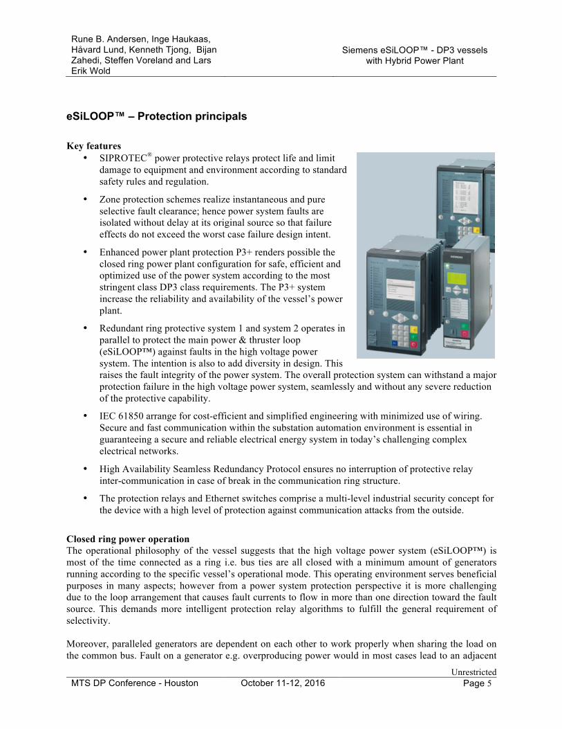
• SIPROTEC® power protective relays protect life and limit damage to equipment and environment according to standard safety rules and regulation.
• Zone protection schemes realize instantaneous and pure selective fault clearance; hence power system faults are isolated without delay at its original source so that failure effects do not exceed the worst case failure design intent.
• Enhanced power plant protection P3+ renders possible the closed ring power plant configuration for safe, efficient and optimized use of the power system according to the most stringent class DP3 class requirements. The P3+ system increase the reliability and availability of the vessel’s power plant.
• Redundant ring protective system 1 and system 2 operates in parallel to protect the main power & thruster loop (eSiLOOP™) against faults in the high voltage power system. The intention is also to add diversity in design. This raises the fault integrity of the power system. The overall protection system can withstand a major protection failure in the high voltage power system, seamlessly and without any severe reduction of the protective capability.
• IEC 61850 arrange for cost-efficient and simplified engineering with minimized use of wiring. Secure and fast communication within the substation automation environment is essential in guaranteeing a secure and reliable electrical energy system in today’s challenging complex electrical networks.
• High Availability Seamless Redundancy Protocol ensures no interruption of protective relay inter-communication in case of break in the communication ring structure.
• The protection relays and Ethernet switches comprise a multi-level industrial security concept for the device with a high level of protection against communication attacks from the outside.
Closed ring power operation The operational philosophy of the vessel suggests that the high voltage power system (eSiLOOP™) is most of the time connected as a ring i.e. bus ties are all closed with a minimum amount of generators running according to the specific vessel’s operational mode. This operating environment serves beneficial purposes in many aspects; however from a power system protection perspective it is more challenging due to the loop arrangement that causes fault currents to flow in more than one direction toward the fault source. This demands more intelligent protection relay algorithms to fulfill the general requirement of selectivity. Moreover, paralleled generators are dependent on each other to work properly when sharing the load on the common bus. Fault on a generator e.g. overproducing power would in most cases lead to an adjacent
Rune B. Andersen, Inge Haukaas, Håvard Lund, Kenneth Tjong, Bijan Zahedi, Steffen Voreland and Lars Erik Wold
Siemens eSiLOOP™ - DP3 vessels
with Hybrid Power Plant
Unrestricted MTS DP Conference - Houston October 11-12, 2016 Page 6
healthy generator to under produce. Most traditional protection scheme would see both generators as faulty. This is not acceptable when running the vessel in closed ring power configuration. As minimum, the protection system should implement sufficient stabilizing measures to avoid tripping healthy generators. Protection principals The protection philosophy intends to set guidelines for protection schemes which serve the purpose of protecting life and limiting damage to equipment and environment. The protection scheme shall be designed to ensure that faults are isolated and that failure effects do not exceed the worst case failure design intent; loss of one thruster or one engine room. The design follows a set of basic principles. Basically, the design targets simplicity and stability to avoid over-function, and at the same time reliability to avoid under-function. Further,
• The protection system shall detect and isolate the fault according to the worst case failure design intent in all permissible operational breaker arrangements.
• The protection system shall detect and isolate the fault so that faultless part of the power system continues to operate as close to normal as possible.
• Normal fault clearance shall operate so that the faulty part becomes isolated as soon as possible, approx 100 milliseconds. In case of protection system or breaker failure the selectivity shall not exceed the worst case failure design intent.
• All short-circuit faults shall be disconnected by two independent protection systems.
• Protective functions shall never interfere with the normal load capacity of the unit protected, nor shall transient, dynamic or abnormal steady state phenomena owing to coupling operations be interrupted as long as these states do not lead to overload scenarios in the plant.
Speed is safety! Transient conditions and generator dynamics in closed ring operation are proportional sensitive to the duration of zero system voltage during the fault, known as fault ride through. Hence instantaneous fault clearing time is essential in order to ensure safe and stable operation of the main power system. Reduced risk of human errors The protection devices also serve as bay controllers performing breaker control and switchgear interlocking. In this concept, there is less room for human errors. The mechanical close function of the circuit breakers shall be locked off, giving no possibility for human error when closing a breaker to energize or to synchronize a part of the power system. Normal and abnormal conditions The protection system shall basically limit damage and enhance power system reliability. It is designed to recognize a specific abnormal state and to take predetermined action to isolate the fault thus eliminating further hazard in the power system. The pickup may be dropped off due to transient phenomena leading it back to normal state. The type of action depends on the device and on the criticality of the environmental condition that is observed by the device. If the protected object is tripped due to elapsed time the power system will have an outage state that needs to be inspected and restored to normal operation. If the time

Rune B. Andersen, Inge Haukaas, Håvard Lund, Kenneth Tjong, Bijan Zahedi, Steffen Voreland and Lars Erik Wold
Siemens eSiLOOP™ - DP3 vessels
with Hybrid Power Plant
Unrestricted MTS DP Conference - Houston October 11-12, 2016 Page 7
does not exceed the set time delay before pick up is dropped, the device will once again head back to normal state. The device may also take less severe action as alarm only to enable the power system operator to change surrounding environment to a less hazardous condition. Supervisory functions are implemented wherever necessary to inhibit protection functions with subsequent alarm to avoid hidden failures. Alternating current power systems must operate within limits for voltage, frequency and current. Limits for normal state as percentage of nominal values are as follows:
Us Steady state system voltage 97.5% < Us < 102.5%
Ut Transient state system voltage 85.0% < Ut < 120.0%
fs Steady state system frequency 95.0% < fs < 105.0%
ft Transient state system frequency 90.0% < ft < 110.0%
is Steady state current is < 110.0% Protective relays The protection scheme shall be designed to isolate the fault at its original source. There are 4 main protection relays protecting its assigned elements, refer to Figure 3:
• Generator protection device (A) is applied to the stator side of the generator directly connected to the bus bar. The device detects and isolates faults with source in the power generation, i.e. fuel control, exciter control or the generator itself. In addition, P3+ protection and monitoring is applied including interface to AVR and Engine control system in order to detect misbehavior, closed ring mode failures or sub-optimal performance.
• Ring protection system (B) is applied to the bus ties connected to the bus bar. The device detects and isolates faults with source at high voltage bus bar or bus tie cable in addition serving as backup protection in case of protection failure in the generator or feeder. The ring protection is instantaneous, redundant and pure selective.
• Feeder protection device (C) is applied to the feeder connected to the bus bar. The device detects and isolates faults in high voltage load feeder. In case of a Thruster or Drilling drive feeder, the load normally comprises a power converter which holds its own internal protective functions.
• Energy Storage protection device (D) is applied to the energy storage (ES) feeder. The device detects and isolates faults in high voltage feeder and step-up transformer. The load flow is bi-directional, i.e. the energy storage system may be a source or load based on energy management and battery state. The ES comprises a power converter which holds its own internal protective functions for energy storage / battery related failures.
Each switchboard cubicle has one installed protection device that fulfills the purposes for protection, control and communication. Further, the Bus Tie cubicles have redundant device for pure protection purposes.
Rune B. Andersen, Inge Haukaas, Håvard Lund, Kenneth Tjong, Bijan Zahedi, Steffen Voreland and Lars Erik Wold
Siemens eSiLOOP™ - DP3 vessels
with Hybrid Power Plant
Unrestricted MTS DP Conference - Houston October 11-12, 2016 Page 8
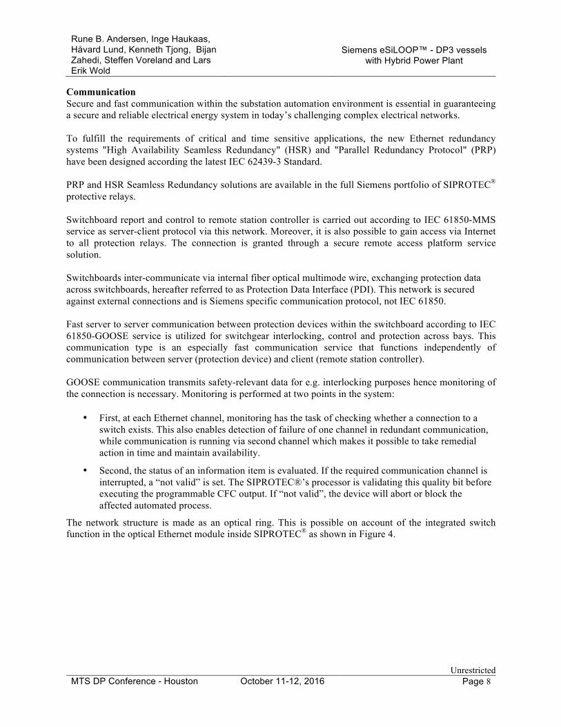
Communication Secure and fast communication within the substation automation environment is essential in guaranteeing a secure and reliable electrical energy system in today’s challenging complex electrical networks. To fulfill the requirements of critical and time sensitive applications, the new Ethernet redundancy systems "High Availability Seamless Redundancy" (HSR) and "Parallel Redundancy Protocol" (PRP) have been designed according the latest IEC 62439-3 Standard. PRP and HSR Seamless Redundancy solutions are available in the full Siemens portfolio of SIPROTEC® protective relays. Switchboard report and control to remote station controller is carried out according to IEC 61850-MMS service as server-client protocol via this network. Moreover, it is also possible to gain access via Internet to all protection relays. The connection is granted through a secure remote access platform service solution. Switchboards inter-communicate via internal fiber optical multimode wire, exchanging protection data across switchboards, hereafter referred to as Protection Data Interface (PDI). This network is secured against external connections and is Siemens specific communication protocol, not IEC 61850. Fast server to server communication between protection devices within the switchboard according to IEC 61850-GOOSE service is utilized for switchgear interlocking, control and protection across bays. This communication type is an especially fast communication service that functions independently of communication between server (protection device) and client (remote station controller). GOOSE communication transmits safety-relevant data for e.g. interlocking purposes hence monitoring of the connection is necessary. Monitoring is performed at two points in the system:
• First, at each Ethernet channel, monitoring has the task of checking whether a connection to a switch exists. This also enables detection of failure of one channel in redundant communication, while communication is running via second channel which makes it possible to take remedial action in time and maintain availability.
• Second, the status of an information item is evaluated. If the required communication channel is interrupted, a “not valid” is set. The SIPROTEC®’s processor is validating this quality bit before executing the programmable CFC output. If “not valid”, the device will abort or block the affected automated process.
The network structure is made as an optical ring. This is possible on account of the integrated switch function in the optical Ethernet module inside SIPROTEC® as shown in Figure 4.

Rune B. Andersen, Inge Haukaas, Håvard Lund, Kenneth Tjong, Bijan Zahedi, Steffen Voreland and Lars Erik Wold
Siemens eSiLOOP™ - DP3 vessels
with Hybrid Power Plant
Unrestricted MTS DP Conference - Houston October 11-12, 2016 Page 9
FIG 4. Operation of Ethernet modules with integrated switch function with HSR protocol
High Availability Seamless Redundancy Protocol In each protective device an Ethernet module with integrated Ethernet switch is used. This operating mode allows high availability seamless redundant communication, also known as HSR (High Availability Seamless Redundancy Protocol). Its characteristic feature is that all devices in the switchboard are arranged in a ring; one external switches must be integrated into this ring for the output of data, e.g. for display or for transmission into a different network. HSR is specified in the norm IEC 62439-3. The indication is sent twice in the both directions of the ring. The receiver gets the indication via 2 ways in the ring, takes the 1st indication, and discards the 2nd. HSR node has a switch function thus, the HSR node forwards indications in the ring that are not addressed. In order to avoid circling indications in the ring, special measures are defined in the case of HSR. SAN (Single Attached Node) end devices can only be connected with a Red Box in the case of HSR. Industrial security The protective device comprises a multi-level industrial security concept for the device with a high level of protection against communication attacks from the outside including:
• Secure authentication between the device and the configuration PC tool (DIGSI®).
• Establishment of connection after password testing: If the optional connection password has been activated for remote access, remote access via the Ethernet cannot take place until the password has been entered. Once the connection has been established, the user has only read access to the device.
• Access control with conformation code: Security prompts must be answered for security-critical actions, e.g., changing parameters, in order to obtain write access to the device. These prompts shall be user configurable, and may be different for different application areas. Accesses to areas of the device with restricted access right shall be recorded. This makes it possible to track which groups had access to protected areas and when. Unsuccessful and unauthorized access attempts shall also be recorded and an alarm may be triggered by an independent telecontrol link.
• In addition, security-critical operations can be recorded in the device. These logs are safeguarded against deletion. All files that can be loaded into the device via the configuration PC tool shall be signed. In this way, corruption from outside by viruses or trojans is reliably detected.
• Unused Ethernet services and the associated ports should be disabled in the device with the configuration PC tool.

Rune B. Andersen, Inge Haukaas, Håvard Lund, Kenneth Tjong, Bijan Zahedi, Steffen Voreland and Lars Erik Wold
Siemens eSiLOOP™ - DP3 vessels
with Hybrid Power Plant
Unrestricted MTS DP Conference - Houston October 11-12, 2016 Page 10
Zone protection Zone protection schemes realize instantaneous and pure selective fault clearance; hence power system faults are isolated so that failure effects do not exceed the worst case failure design intent. The fault is detected and interrupted within its origin source within approx 100 milliseconds. Individual zones are classified as shown in Figure 5.
52
52
52 52
G2
52
52
52 52
52
ES1
52
G1 G3
52 52
A A A
B
B
B
B
B
C
C
D
T2
G4,G5,G6
T1
52
52
T4
B
FIG 5. Zone protection scheme
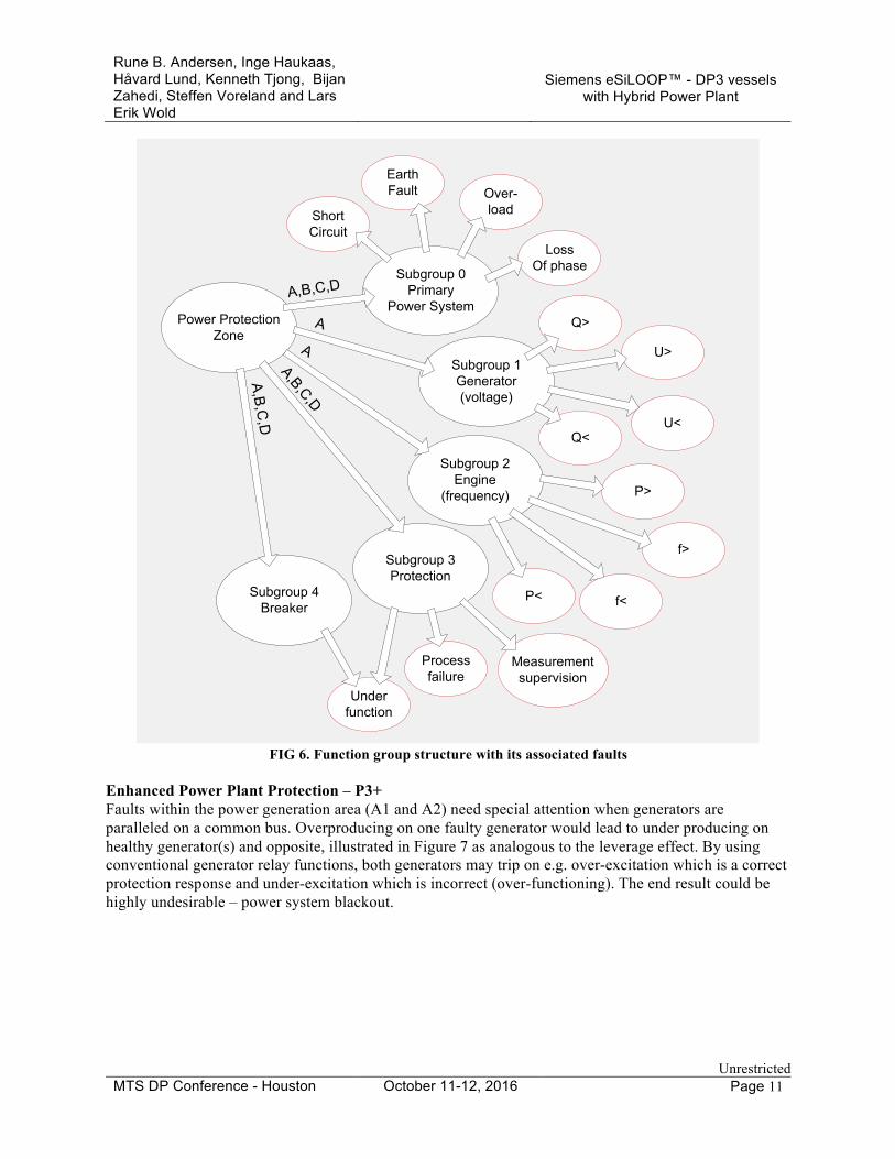
Protective function groups within zone A, B, C or D with sub category 0 detect basic faults that origin in the primary power system e.g. short circuit, earth fault, loss of phase etc. Subgroup 1 and 2 detects fault inside the power generation control system e.g. voltage or frequency problems due to faulty/ abnormal voltage or speed governor performance. Subgroup 3 detects fault inside the secondary protection system i.e. relay not able to trip, measurement supervision failure, process failure etc., and 4 detects fault inside the circuit breaker itself i.e. not able to open. Fault tree structure with respect to function groups are shown in Figure 6.
Rune B. Andersen, Inge Haukaas, Håvard Lund, Kenneth Tjong, Bijan Zahedi, Steffen Voreland and Lars Erik Wold
Siemens eSiLOOP™ - DP3 vessels
with Hybrid Power Plant
Unrestricted MTS DP Conference - Houston October 11-12, 2016 Page 11
Subgroup 0Primary
Power System
Subgroup 1Generator(voltage)
Subgroup 2Engine
(frequency)
Subgroup 3Protection
Subgroup 4Breaker
ShortCircuit
EarthFault Over-
load
LossOf phase
Q>
U>
U<Q<
P>
f>
f<P<
Underfunction
Power ProtectionZone
A,B,C,D
A
A
A,B,C,D
A,B,C,D
Process failure
Measurement supervision
FIG 6. Function group structure with its associated faults
Enhanced Power Plant Protection – P3+ Faults within the power generation area (A1 and A2) need special attention when generators are paralleled on a common bus. Overproducing on one faulty generator would lead to under producing on healthy generator(s) and opposite, illustrated in Figure 7 as analogous to the leverage effect. By using conventional generator relay functions, both generators may trip on e.g. over-excitation which is a correct protection response and under-excitation which is incorrect (over-functioning). The end result could be highly undesirable – power system blackout.

Rune B. Andersen, Inge Haukaas, Håvard Lund, Kenneth Tjong, Bijan Zahedi, Steffen Voreland and Lars Erik Wold
Siemens eSiLOOP™ - DP3 vessels
with Hybrid Power Plant
Unrestricted MTS DP Conference - Houston October 11-12, 2016 Page 12
52
52
G2G1 G3
52 52
Consumer
ExportImportImport
FIG 7. Faulty overproducing generator driving the others in reverse analogous to the leverage effect
In order to mitigate risk of power system blackout it is required to implement an advanced generator protection scheme that can identify the faulty generator and isolate the fault from the remaining healthy power system. Solution is found by invention of Siemens P3+ which stabilizes and safeguards individual generators with common mode fault condition(s). The autonomous generator protection relay has the capability to safeguard healthy generator and simultaneously detect and isolate faulty generator. Siemens P3+ introduces enhanced Power Plant Protection for all types of offshore vessels. The P3+ is an evolutionary product of future proof power plant protection for offshore industry in compliance with the highest standard requirements for DP3 class vessels. The P3+ is based on the original Siemens P3 which is a well proven technology in the marine and shipbuilding industry since 2005, and is today in operation in more than 100 vessels. The diesel-electric propulsion power station contains all standard protection units for circuit breakers (e.g. for over-current, reverse power, differential protection), as is expected of a power system. However, it is necessary for a diesel-electric power system to ensure a 100 % selective trip of faulty generator sets to avoid loss of power and propulsion, especially during closed bus-tie operation. Utilization of a comprehensive supervision system such as the P3+ is therefore absolutely necessary. The P3+ system is a generator set supervision system that analyzes every abnormal system condition resulting from long term unacceptable behavior and/or:
• Engine over-producing true power (P>) including loss of speed sensing
• Engine under-producing true power (P<) including reverse power
• Generator over-producing reactive power (Q>) including loss of voltage sensing

Rune B. Andersen, Inge Haukaas, Håvard Lund, Kenneth Tjong, Bijan Zahedi, Steffen Voreland and Lars Erik Wold
Siemens eSiLOOP™ - DP3 vessels
with Hybrid Power Plant
Unrestricted MTS DP Conference - Houston October 11-12, 2016 Page 13
• Generator under-producing reactive power (Q<) including loss of field
• Failure in gen set secondary circuits including measurement supervision / process failure
• System frequency and/or voltage abnormalities including hunting
Long term is here defined to situations with more than 200 milliseconds elapse time. The main task of the P3+ is to analyze the gensets as single sets and as common power station to:
• Provide selective trip of correct genset in conditions related to exciter control and engine / fuel control problems
• Provide alarm to Power Management for system abnormalities in order for operator to take proper actions
• Provide backup of P3+ for other gensets
Following a power system fault event the next step to obtain a secure operation (start of standby generator) will be taken care of by the Power Management System. P3+ comprises stand-alone protective device technology type tested among others according to IEC 60255, IEC 60870 and IEC 61000 with an autonomous CPU in each generator cubicle providing sufficient power to analyze the power station. No cross connections between gensets / redundancy groups are required. The device retrieves local generator stator measured values with additional interface to generator AVR, engine control system and IEDs assigned to bus segment via IEC 61850 – GOOSE. Multiple communication networks, protocols and IOs may be extended with device plug-in modules in case of special requirements. Redundant ring protection of main power & thruster loop Multifunctional differential & overcurrent protection relays in each terminal end of the protected object communicates differential current in addition to fault current directionality for eSiLOOP™ protection arrangement; thus providing new dimension of information in the protection scheme. The device creates a protection zone around the protected object, being either a bus bar or a tie cable, providing redundancy with genuinely selective and instantaneous fault clearing. Only the faulty section is tripped so that faultless part of the power system continues to operate as close to normal as possible. Bus Tie cubicles are equipped with two ring protection systems:
System 1: Master & Slave comprise functions 67BB-1, 67NBB-1, 87(N)L-1
System 2: Master & Slave comprise functions 67BB-2, 67NBB-2, 87(N)L-2
Rune B. Andersen, Inge Haukaas, Håvard Lund, Kenneth Tjong, Bijan Zahedi, Steffen Voreland and Lars Erik Wold
Siemens eSiLOOP™ - DP3 vessels
with Hybrid Power Plant
Unrestricted MTS DP Conference - Houston October 11-12, 2016 Page 14
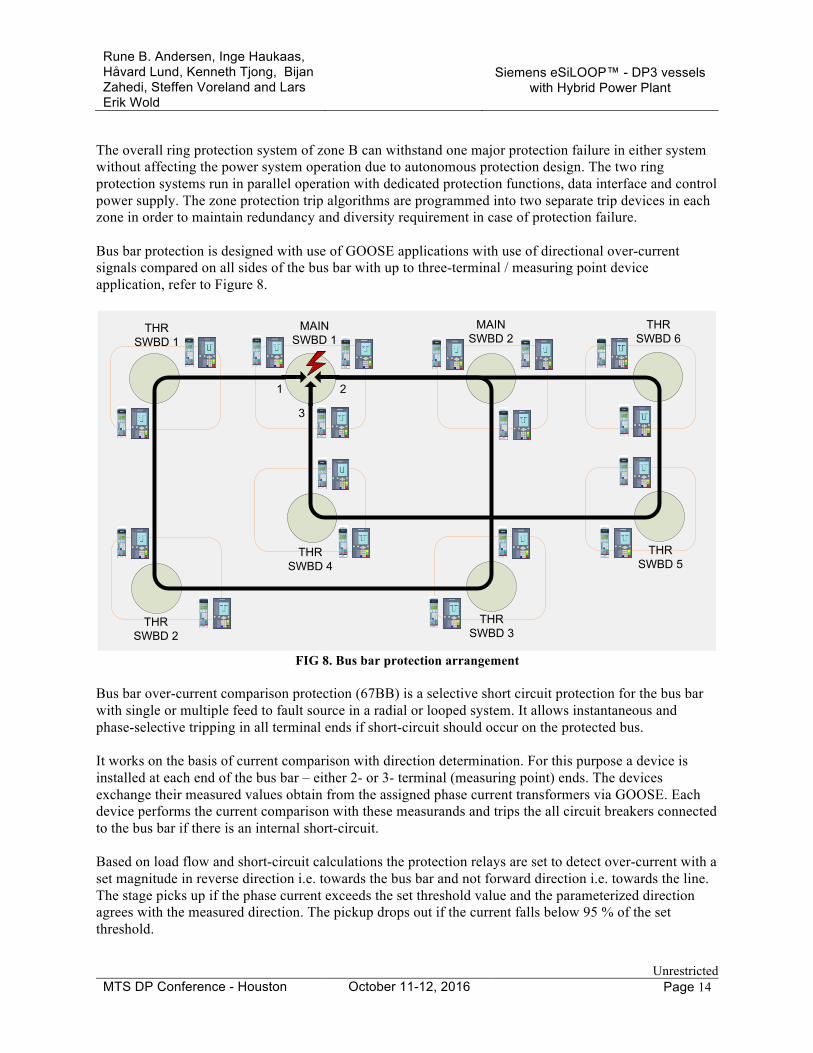
The overall ring protection system of zone B can withstand one major protection failure in either system without affecting the power system operation due to autonomous protection design. The two ring protection systems run in parallel operation with dedicated protection functions, data interface and control power supply. The zone protection trip algorithms are programmed into two separate trip devices in each zone in order to maintain redundancy and diversity requirement in case of protection failure. Bus bar protection is designed with use of GOOSE applications with use of directional over-current signals compared on all sides of the bus bar with up to three-terminal / measuring point device application, refer to Figure 8.
THRSWBD 1
1 2
3
THRSWBD 2
THRSWBD 3
THRSWBD 4
THRSWBD 5
THRSWBD 6
MAINSWBD 1
MAINSWBD 2
FIG 8. Bus bar protection arrangement
Bus bar over-current comparison protection (67BB) is a selective short circuit protection for the bus bar with single or multiple feed to fault source in a radial or looped system. It allows instantaneous and phase-selective tripping in all terminal ends if short-circuit should occur on the protected bus. It works on the basis of current comparison with direction determination. For this purpose a device is installed at each end of the bus bar – either 2- or 3- terminal (measuring point) ends. The devices exchange their measured values obtain from the assigned phase current transformers via GOOSE. Each device performs the current comparison with these measurands and trips the all circuit breakers connected to the bus bar if there is an internal short-circuit. Based on load flow and short-circuit calculations the protection relays are set to detect over-current with a set magnitude in reverse direction i.e. towards the bus bar and not forward direction i.e. towards the line. The stage picks up if the phase current exceeds the set threshold value and the parameterized direction agrees with the measured direction. The pickup drops out if the current falls below 95 % of the set threshold.

Rune B. Andersen, Inge Haukaas, Håvard Lund, Kenneth Tjong, Bijan Zahedi, Steffen Voreland and Lars Erik Wold
Siemens eSiLOOP™ - DP3 vessels
with Hybrid Power Plant
Unrestricted MTS DP Conference - Houston October 11-12, 2016 Page 15
A reverse interlocking of the scheme maintains selectivity in case of a short circuit in generator incomer or transformer feeder. In case of a fault inside generator, the generator protection relay issues a differential current picked up signal to the trip device which then blocks the protection function 67BB. Likewise, in case of a fault inside the transformer feeder, the feeder protection relay issues an over-current picked up signal to the trip device which then blocks the protection function 67BB. In this regard, 67BB also works as a backup protection for generators and feeders assigned to the protected bus since no reverse interlocking signal is received in case of protection failure in the generator incomer or feeder. The 67BB function is only active if there is detected severe under-voltage in order to differentiate a short-circuit current from a high load current flowing into the protected zone. The systems also comprise Bus bar ground fault current protection (67NBB) which is a selective ground over-current protection for the bus bar with single or double feed to fault source in a radial or looped system. It allows phase-selective tripping in all terminal ends if earth faults conditions should occur on the protected bus. It works on the basis of current comparison with direction determination of the earth current (INs) used as measurand from the cable core current transformer. The devices exchange their measured values obtain from the assigned phase current transformers via GOOSE. The stage picks up if the earth current exceeds the set threshold value, normally 20% referred to maximum earth fault current, and the parameterized direction agrees with the measured direction. The direction determination takes place with the measured INs and U0 calculated from the measured phase-to-ground voltages from the bus bar voltage transformer. The forward and reverse region is defined through settable angle parameters rendering forward or reverse direction similar to 67BB. Unbalance in operation and unbalanced transformer ratios can lead to spurious pickups and incorrect tripping. In order to avoid this, the 67NBB detection is stabilized with the requirement of zero sequence voltage exceeding the set threshold of U0>. Selectivity within the protected bus is maintained with time-current discrimination. Current threshold is and time is set above fault detection in generators or feeders assigned to the protected bus, typically settings are 20% of maximum earth fault current, 10% of maximum displacement voltage with a function time delay of 2 seconds. Bus Tie cable protection is designed with use of PDI application exchanging differential signals compared on both sides of the protected cable, refer to Figure 9. Cable differential protection (87(N)L) is utilized for protected objects with 2 ends. For this a device is installed at each end of the protected cable. The devices exchange their measurands via internal communication connections PDI. The basic principle of the differential protection is based on the precondition that, during uninterrupted operation, the sum of all currents flowing into the protected object equals 0. Each device performs the current comparison with these measurands and trips the assigned circuit breaker, if there is an internal short circuit. The current transformers selectively delimit the protection range.

Rune B. Andersen, Inge Haukaas, Håvard Lund, Kenneth Tjong, Bijan Zahedi, Steffen Voreland and Lars Erik Wold
Siemens eSiLOOP™ - DP3 vessels
with Hybrid Power Plant
Unrestricted MTS DP Conference - Houston October 11-12, 2016 Page 16
1
2
THRSWBD 1
THRSWBD 2
THRSWBD 3
THRSWBD 4
THRSWBD 5
THRSWBD 6
MAINSWBD 1
MAINSWBD 2
FIG 9. Bus tie protection arrangement

Rune B. Andersen, Inge Haukaas, Håvard Lund, Kenneth Tjong, Bijan Zahedi, Steffen Voreland and Lars Erik Wold
Siemens eSiLOOP™ - DP3 vessels
with Hybrid Power Plant
Unrestricted MTS DP Conference - Houston October 11-12, 2016 Page 17
eSiLOOP™ – Energy Storage Systems The Energy Storage Systems is an autonomous string which includes:
• Multiple battery strings with Battery Management Systems • DC/AC controller for connection to the AC switchboard • Step-up transformer to match the bus voltage • Incomer cubicle in an AC switchboard with protection unit • PLC / controller for
o Adjusting power output based on system load (charge/ discharge control) o Interface to Power Management System o Control and interface to Battery Management System
Figure 10 Energy Storage Systems
The Energy Storage System will be independent of the top system – the control is set to the lowest possible level, thus no need of the PMS in order to achieve load control. The ESS will know the system load based on the frequency – diesel generators are operated in frequency droop control. The Energy Storage Systems will work based on three main principles; optimize diesel load, even out the power consumption (peak shaving), and to store energy for fault scenarios. Optimize diesel load The Energy Storage System adjusts its power consumption in order to maintain constant and optimal load (typically close to 85%). If system power is higher, the Energy Storage System will supply power to the grid in parallel with the diesel generators and act as a consumer when system load is lower. If the ESS is supplying power for a prolonged time and the battery energy level becomes low – a “start request” will be sent to the PMS for a new diesel generator. When online the ESS will optimize the load for all connected diesel generators and slowly recharge the batteries. Low load condition over time will cause shutdown of a diesel generator in order to save fuel based on “low load” and existing PMS functionality.

Rune B. Andersen, Inge Haukaas, Håvard Lund, Kenneth Tjong, Bijan Zahedi, Steffen Voreland and Lars Erik Wold
Siemens eSiLOOP™ - DP3 vessels
with Hybrid Power Plant
Unrestricted MTS DP Conference - Houston October 11-12, 2016 Page 18
Figure 11 Specific fuel consumption for a diesel motor
Peak shaving One of the main reasons to keep several diesel generators connected is to achieve sufficient “change rate” in respect to power transients. The system is then more optimized for power demand/change and less for optimal energy consumption. The ESS is more adapted for sudden load changes and provides a very good flexibility in combination with the diesel generators. The diesel generators will provide the base load while the ESS is set to even out load fluctuation. The batteries will always be recharged in order to have backup power in case of loss of one large consumer. The power from the batteries can be applied instantaneously, thus no need to take into account any delays , as typically seen for a diesel engine.
Figure 12 Peak shaving – sliding average

Rune B. Andersen, Inge Haukaas, Håvard Lund, Kenneth Tjong, Bijan Zahedi, Steffen Voreland and Lars Erik Wold
Siemens eSiLOOP™ - DP3 vessels
with Hybrid Power Plant
Unrestricted MTS DP Conference - Houston October 11-12, 2016 Page 19
Blackout prevention – Emergency power Running with reduced number of connected diesel generators (down to one) calls for backup energy in case of loss of this prime mover. The ESS has the possibility to instantly provide power if a large producer is lost. This has been proven for several systems with ESS where it pre-fault was charging to suddenly supplying at maximum output power when the diesel-generator was tripped. The ESS is set up to have spare capacity for such use. Typically up to 20% of the battery capacity is preserved for peak shaving. The remaining energy is set aside for emergency power. The energy backup is always taking into account uncertainty of the energy level of the batteries and aging affects. This energy should be sufficient for safely produce enough power to shut down the operation and move the platform. This will be weather and operation dependent, but typically 15-45 minutes. This is referred to as “Time to Terminate” operation. Running on batteries only, may also be beneficial in case of a gas-leakage where diesel generators must be shut down. In such an event the batteries may continue to operate and provide power to thrusters while the platform moving to a safe area.
0%10
0%
90%
”Energy reserve for time to terminate operation” · Uses more of the energy reserves· ”Time to terminate” operation
”Prefered use of batteries”· Peak shaving· Energy buffer· Optimalization of diesel load
70%
20%
Figure 13 Battery State of Charge

Rune B. Andersen, Inge Haukaas, Håvard Lund, Kenneth Tjong, Bijan Zahedi, Steffen Voreland and Lars Erik Wold
Siemens eSiLOOP™ - DP3 vessels
with Hybrid Power Plant
Unrestricted MTS DP Conference - Houston October 11-12, 2016 Page 20
eSiLOOP™ – Power system Dynamic Simulations The detailed dynamic study of the power plant is carried out by SimPowerSystem toolbox of MATLAB /Simulink. An overview of the simulation platform is shown in Figure 14. In the system model, the detailed dynamic models of the generators, excitation systems, and governors are taken into account. Different number of diesel generators can be readily simulated in parallel under isochronous or droop mode of operation.
Figure 14 - Overview of the simulation platform for the hybrid power plant
The Energy Storage Systems are also modeled by the detailed dynamics of the battery, as well as the inverter. The inverter control includes various function modules such as Grid Droop Control, Dynamic Grid Support, Grid Synchronization, and Closed-loop Current control. These function modules are implemented in the system model as they are important in dynamic analysis of the system. The mentioned simulation platform is used in study of different dynamic events, such as fault ride through, generator trip, load trip, motor start, regenerative braking, etc. In the following, a few case studies for a hybrid power plant are illustrated as examples. Case Study 1 – Generator Trip The hybrid power plant in a closed ring configuration allows DP3 operation with only one online generator to save fuel and the environment. The onboard energy storage provides necessary power and energy reserve in case a single running generator fails until another diesel-generator starts and takes over. The schematic of Figure shows a configuration with one active diesel generator rated at 6 MW in parallel with six ESS units each with 1MWh energy capacity. Before the trip, the diesel-generator is loaded by approximately 0.85 pu, which is the optimized operating point (Figure 16b). This optimization is done by load leveling function of the ESS units. As seen in Figure 16c, each ESS is being charged by approximately 0.2 pu to bring the diesel engine work point close to the optimized value. At t = 8 sec, as the generator trips, the ESS’s adapt to the new conditions by immediately changing from charge mode to

Rune B. Andersen, Inge Haukaas, Håvard Lund, Kenneth Tjong, Bijan Zahedi, Steffen Voreland and Lars Erik Wold
Siemens eSiLOOP™ - DP3 vessels
with Hybrid Power Plant
Unrestricted MTS DP Conference - Houston October 11-12, 2016 Page 21
discharge mode, and start to supply the loads. The simulation results show that the voltage and frequency variations during the transient remain well within the class requirements.
Figure 15 – Trip of the only online generator in parallel with six ESS’s
16a▲( generator terminal voltage and generator current)
16b▲( generator electrical/mech. powers, torque, and frequency)

Rune B. Andersen, Inge Haukaas, Håvard Lund, Kenneth Tjong, Bijan Zahedi, Steffen Voreland and Lars Erik Wold
Siemens eSiLOOP™ - DP3 vessels
with Hybrid Power Plant
Unrestricted MTS DP Conference - Houston October 11-12, 2016 Page 22
16c▲(active/reactive powers, voltage, and frequency of each ESS)
Figure 16 – Simulation results of the generator trip

Rune B. Andersen, Inge Haukaas, Håvard Lund, Kenneth Tjong, Bijan Zahedi, Steffen Voreland and Lars Erik Wold
Siemens eSiLOOP™ - DP3 vessels
with Hybrid Power Plant
Unrestricted MTS DP Conference - Houston October 11-12, 2016 Page 23
Case Study 2 – Fault Ride Through The schematic of Figure 17 shows a configuration of two generators in parallel with six ESS units. In this case study, a fault occurs on a feeder and clears by the protection system. The simulation results are shown in Figure 18.
Figure 17 – Fault ride through case for two online generators in parallel with six ESS’s
18a▲( generator terminal voltage and generator current)

Rune B. Andersen, Inge Haukaas, Håvard Lund, Kenneth Tjong, Bijan Zahedi, Steffen Voreland and Lars Erik Wold
Siemens eSiLOOP™ - DP3 vessels
with Hybrid Power Plant
Unrestricted MTS DP Conference - Houston October 11-12, 2016 Page 24
18b▲( generator electrical/mech. powers, torque, and frequency)
18c▲(active/reactive powers, voltage, and frequency of each ESS)
Figure 18 – Simulation results of Fault Ride Through
As seen in Figure 18b, the active power absorbed by the short circuit fault is close to zero. Therefore, the engine speed increases until the engine mechanical power is brought down by the governor. Although the engine was highly loaded before the fault, which creates worst frequency variations at such transients, the frequency remains within the class limits of ±10% throughout the simulation. Regarding the voltage transients, the largest voltage variations are normally seen just after the fault clearance. Figure 18a shows that the post-transient voltage overshoot is well below the class limit of +20%.
Rune B. Andersen, Inge Haukaas, Håvard Lund, Kenneth Tjong, Bijan Zahedi, Steffen Voreland and Lars Erik Wold
Siemens eSiLOOP™ - DP3 vessels
with Hybrid Power Plant
Unrestricted MTS DP Conference - Houston October 11-12, 2016 Page 25
Another point in the fault ride through study is how the ESS acts under short circuit. As shown by Figure 18c, each ESS injects reactive power of 1.2 pu to the short circuit fault. This provides a sustained short circuit current which enables the protective relays to detect and locate the fault.
Conclusion
The eSiLOOP™ offer increased reliability and safety for the vessel and also giving a significant CAPEX and OPEX reduction by;
q Dual redundant power distribution q Worst Case Failure is reduced to loss of ONE thruster or ONE engine room q Use of Energy storage “Syntetic generators” will increase safety and reduce emissions q Ratings or numbers of thrusters and engines can be reduced offering a CAPEX reduction q Reductions of engine maintenance, fuel consumption and emission giving a significant OPEX
saving